1
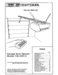
Owners Manua
\
Door Opener
39°535006
CAUTION:
READ INSTRUCTIONS
FOR SAFE OPERATION
AND RULES
CAREFULLY,
FASTEN THIS MANUAL
NEAR THE GARAGE
DOOR AFTER INSTALLATION°
PERIODIC
CHECKS OF OPENER ARE REQUIRED
TO INSURE SATISFACTORY
OPERATION,,
BNDEX
Page
Features
of Your Opener ................
Specifications
...............................
You'll Need Tools ............................
Safety Rules ..................................
Carton
Check List ............................
Accessories
....................................
Identify
Your Door Type ..................
Assembly
...........................................
Installation
..........................................
Adjustment
................................
Operation
of Your Opener
..................
Radio Controls
..........................
Having a Problem? .......................
Transmitter
Schematic
...................
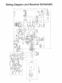
Wiring
Diagram .............................
Receiver Schematic
.....................
Repair Parts, Rail Assembly
...........
Repair Parts, Installation
...............
Repair Parts, Chassis
Assembly
........
How to Order Repair Parts .............
Maintenance
Agreements
..........
Sears Warranty
.................................
2
2
2
3
4
5
5
6
10
18
21
22
24
24
25
25
26
26
27
28
28
28
FEATURES
OF YOUR
OPENER
1o Opener
Lights:
Turn on and off automatically,
with 4-1/2 minute illumination
for your safety and
convenience.
Provide constant
light when Work
Light control button is pressed..
5_ Motor Power: 1/2 horsepower
permanently
cated motor with automatic reset
2,. Safety System:
Independent
up and down force
adjustment.. Door reverses automatically
when ob structed
in DOWN direction
Door STOPS when
obstructed
in UP dkection
3o Emergency
Disconnect:
Putl cord disconnect
permits manual door operation.
7o Easy Limit Adjustment:
Limits of door opening
and closing adjusted by turning screws without removing chassis cover:.
8, Vacation
Push Button: When the Vacation Push
Button is ON, the openerwill
not operate from the
transmitter. The door will operate in the UP direction ONLY from the Wall Control (or optional Key
Switch accessory, Page 5)
4o Automatic
Reconnect:
Trolley halves reconnect
for automatic operation when opener is energized
after emergency
disconnect.
lubri-
6., Digital Radio Controls:
19,683 codes from which
to choose Can be changed easily by the owner..
SPECIFICATIONS
MOTOR
Type .
Speed
Volts ._
Current
1/2 horsepower
permanent
t500 rpm
120 Volts AC - 60 Hz Only
4 5 amperes
DRIVE
Gear reduction
Drive
Lubrication
Length of Travet
Travel rate
Lamp
Door linkage
YOU'LL
SAFETY
split capacitor
Personal
Push button & automalic
direction.
Push button
in up direction
Independent
up & down
screws
Motor overload protector
push button wiring
Circuit actuated by limit
Screwdriver
adjustrnenl
Low voltage push button
Electronic
MECHANISM
Electrical
16:1
Chain & cable with two-piece
trolley on
steel Tee rail
Motor is setfqubricated.
Drive shaft bronze
off-life bearings
Adjustable
to 7-1/2 feet
6 to 8 inches per second
On when door starts
in travel, off 4-1/2
minutes
after stop, Also separate
Work
Light push button
Adjustable
door arm
PuIi cord
trofley
release
Limit
Limit
Start
device ....
adjustment
circuit
reversal in down
& automatic
stop
force adjustment
and low voltage
nut
on side panel
or radio controI
DIMENSIONS
Length (overall)
. .
Headroom
required
Shipping
Weight
122-t/2
inches
2 inches
43 pounds
NEED TOOLS
During assembly
and installation
of your opener, the instruction
will call for use of various hand tools. Have a
stepladder
handy, and those tools illustrated below: Hammer, electric drill (also 3/16" and 5/16" drill bits), screw
driver, adjustable
end wrench or socket wrench kit, wire cutters, tape measure, pliers and hack saw.
Hack
Pliers
Saw
Tape Measure
Wire Cutters
Claw Hammer
Screwdriver
Stepladder
Adjustable
Electric
Drili
Socket
Wrench
End Wrench
THIS SAFETY ALERT SYMBOL
MEANS CAUTION
-- PERSONAL
STRUCTION.,
READ THESE INSTRUCTIONS
CAREFULLY,
THIS GARAGE DOOR OPENER
PROVIDED
IT IS INSTALLED
SAFETY INSTRUCTIONS.,
IS DESIGNED
AND TESTED
AND OPERATED
IN STRICT
FAILURE TO COMPLY WITH THE FOLLOWING
INJURY OR PROPERTY DAMAGE,.
KEEP GARAGE DOOR BALANCED.. STICKING
OR BINDING
DOORS MUST BE REPAIRED..
OR PROPERTY
DAMAGE
IN-
TO OFFER REASONABLY
SAFE SERVICE
ACCORDANCE
WITH THE FOLLOWING
MAY RESULT
IN SERIOUS
PERSONAL
DO NOT USE FORCE ADJUSTMENTS
TO COMPENSATE
FOR A BINDING
OR STICKING
GARAGE DOOR, EXCESSIVE
FORCE WILL INTERFERE WITH THE PROPER OPERATION
OF
THE SAFETY REVERSE SYSTEM OR DAMAGE
GARAGE DOORS, DOOR SPRINGS,
CABLES,
PULLEYS, BRACKETSANDTHEtR
HARDWARE
MAY BE UNDER EXTREME TENSION AND CAN
CAUSE SERIOUS PERSONAL INJURY° DO NOT
ATTEMPT
ADJUSTMENTS.
CALL A GARAGE
DOOR SERVICEMAN
TO MOVE_ LOOSEN
ADJUST DOOR SPRINGS OR HARDWARE.
INSTRUCTIONS
SAFETY
THE GARAGE
DOOR,, (SEE
PAGE
19),.
OR
FASTEN TH E CAUTION
LABEL ON THE WALL
NEAR THE WALL CONTROL
AS A REMINDER
OF SAFE OPERATING
PROCEDURES_
DO NOT WEAR RINGS, WATCHES
OR LOOSE
CLOTHING WHILE INSTALLING OR SERVICING
A GARAGE DOOR OPENER°
TO AVOID SERIOUS PERSONAL INJURY FROM
ENTANGLEMENT,
REMOVE ALL ROPES CONNECTED TO THE GARAGE DOOR BEFORE INSTALLING
THE GARAGE DOOR OPENER..
INSTALL THE WALL CONTROL (OR ADDITIONAL PUSH BUTTONS)
OUTOFTHE
REACH OF
CHILDREN,
DO NOT ALLOW CHILDREN
TO
OPERATE WALL CONTROL OR TRAN SM ITTERo
SERIOUS PERSONAL
INJURY FROM A CLOSING GARAGE DOOR MAY RESULT FROM ANY
MISUSE OFTHE
OPENER.
DISENGAGE
ALL EXISTING
GARAGE DOOR
LOCKS TO AVOID DAMAGE TO GARAGE DOOR.
CAUTION:
INSTALLATION
AND WIRING MUST BE IN COMPLIANCE WITH LOCAL BUILDING
AND ELECTRICAL CODES..
LIGHTWEIGHT
DOORS
TIAL REINFORCEMENT
DAMAGE.
THE
(SEE
SAFETY
ACTIVATE
OPENER
ONLY
WHEN
THE DOOR IS IN FULL VIEW, FREE OF OBSTRUCTION
AND OPENER IS PROPERLY ADJUSTED,, NO ONE SHOULD
ENTER OR LEAVE
THE GARAGE WHILE
DOOR IS IN MOTION.,
DO NOT ALLOW CHILDREN
TO PLAY NEAR
DOOR.,
REQUIRE
SUBSTAN _
TO AVOID
DOOR
PAGE 10)o
REVERSE
SYSTEM
TEST
USE EMERGENCY
RELEASE
ONLY TO DISENGAGE TROLLEY.
DO NOT USE RED EMERGENCY RELEASE ROPE AN D HAN DLE TO PULL
DOOR OPEN OR CLOSED°
IS IM-
PORTANT (SEE PAGE 20)4 THE GARAGE DOOR
MUST REVERSE
ON CONTACT
WITH A ONEINCH OBSTACLE
PLACED ON THE FLOOR..
FAILURE TO PROPERLY ADJUST THE OPENER
MAY. RESULT IN SERIOUS PERSONAL
INJURY
FROM A CLOSING
GARAGE DOOR. REPEAT
TH E TEST AT LEAST ONCE A YEAR AN D MAKE
ANY NEEDED
ADJUSTMENTS,.
DISCONNECT
ELECTRIC POWER TO GARAGE
DOOR OPENER
BEFORE
MAKING
REPAIRS
OR REMOVING
COVERS_
3
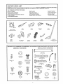
CARTON
CHECK
LIST
SEARS has packaged your Garage Door Opener in two cartons THE RAtLASSEMBLY
CARTON CONTAI NS: a
three-piece
rail, two hanging straps, straight door arm section* and rail assembly hardware,,
THE OPENER CARTON CONTAINS:
Header Bracket*
Walt Control
Opener Chassis
4-Strand BeFI Wire*
Plastic Light Lenses (2)
Sprocket Cover*
Owners Manuar
Cable Pully Bracket*
Transmitter
and Clip (1)
Door Bracket & Plate*
Chain & Cable (in dispenser
carton)*
Hardware Bag
(includes
Caution Label)
2-Piece Trolley*
Wedge Door Arm Section*
*ILLUSTRA'T'ED BELOW
Inner
Trolley
Chain & Cable
in Dispenser
Carton
Outer
Trolley
Sprocket
Cover
J
Cable
PulIey
Bracket
Header
Bracket
Door Bracket
and Plate
SEPARATE
ALL HARDWARE
ASSEMBLY
FOR ASSEMBLY
Chain
Retainer
Bracket
4 Strand
Bell Wire
AND
INSTALLATION
HARDWARE
Door Arm
(Wedge & SIraighl
Sections)
PROCEDURES
INSTALLATION
AS SHOWN
BELOW,.
HARDWARE
ol
Clevis Pin
5/'i6 " x 2_3/4-
(_
fl
Lockwasher
5/16"(3)
Master
5/16"-t8x2-1/2
12)
Washered
Screw
5116".
18xl/2'
(4)
*(2 mounted
in Chassis)
Link
(2}
Rope
5/16"
Cotter Pin
(3)
- 18xl-7/8'
(4)
]L'sI I:IC oo
Nut
5116"18
(6)
8AB x 1"
Carriage Bol!
II4"'-20x1/2'
(4}
@
Lock Nut
t/4" -20
(4)
Hex Screw
5/16"18 x 7/8
(2)
g
Handle
4
Insulated
Staple (18)
5/16'° x t"
Clevis
(2) Pin
(2)
_e
5/16"-18
(4)
w
x 7/8-
Lock Washer
5/t6"(6)
Nul
5116"18
(6}
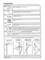
Accessories
Sears offers many useful accessories
bers and descriptions.
53708 _
for you r garage
door open er, They are illustrated
EXTRA TRANSMITTER:
53716
_
53703
_//
TOUCH
outside
OPEN
.................
_,_.,_
_
• ,.... _,. _;
visor clip,,
CODE LOCK: Enables homeowner to open the garage door opener
by entering code on specially designed keypad,
OUTDOOR
transmitter
53717
Includes
below with Sears stock n u m-
KEY SWITCH:
is not handy
DOOR INDICATOR:
Opens the garage
Provides
door automatically
an illuminated
signal
from the
from outside
when
when your garage
door
is open
53702
QUICK RELEASE KEY LOCK: Allows manual operation of your garage door from the
outside in case of power failure orwhere
there is no service entrance
For wood or
metal doors only
53710
_'_
_i
t
_'J "
'_FRARED
:'7
REVERSING
SENSOR:
An optional
system
which
provides
auxiliary
to
your door
down buitt
cycte into
andyour
transmit
to the
opener,
opener
support
to thewhile
safetyin the
features
opener.a signal
Sensors
detect
any The
obstruction
will cause a closing door to reverse and prevent an open door from closing.,
4
IDENTIFY
SECTIONAL DOOR
CURVED TRACK
Highest
Point
of TraveI
YOUR DOOR TYPE
ONE PIECE DOOR
NO TRACK
JAMB HARDWARE
Highest
Poinl
of Travel
FROM
THESE
ILLUSTRATIONS
ONE PIECE DOOR
HORIZONTAL
TRACK
JAMB HARDWARE
Highest
Point
ONE PIECE DOOR
NO TRACK
PIVOT HARDWARE
of Travel
Highest
÷
Point of Travel
"
._/
t
tI
i
Track
"
II
Door
l_ck
.Jamb
Hardware
Door
,
//
CERTAIN INSTALLATION PROCEDURES VARY ACCORDING TO GARAGE DOOR TYPES. WHERE
OCCUR,
BE SURE TO FOLLOW
ONLY
THOSE
INSTRUCTIONS
WHICH
APPLY TO
i CONSTRUCTION
r
....
ii
DIFFERENCES
YOUR
DOOR
Assembmy
TO AVOID INSTALLATION
DIFFICULTIES,
COMPLETED
STEP 8, PAGE 15.
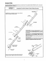
STE P I
DO NOT RUN THE
Assemble
GARAGE
DOOR OPENER
UNTIL
YOU HAVE
Tee Rail & Attach Cable Pulley Bracket
,.,,i
::::=
TEE RAIL BACK
(TO CHASSIS
CAUTION: Do not tighten the lock
necks are seated in square holes°
nuts until bolt
./
TeeRail
_'
V
/A
/////
(End Section___
"eL_
_,_
/
C.r.._ea0,
,_/7_ki_
!f 4".20xl/2''
Tee Rail
(Center Section
'_.
1/4"
PROCEDURE:
Place the 3 Tee rail sections on a flat
surface for assembly. TH IS IS IMPORTANT.
The center
section has two connection flanges., The end sections
are identical.
Flange
Lock Nut
Refer to illustration. BE SURE CENTER SECTION IS
POSITIONED
ON THE CORRECT
SIDE OF TEE
RAIL. (When assembled, Tee rail has a front-to-back
position as shown).
Bolt center rail section to end sections with the hardware illustrated_
SQUARE NECKS ON CARRIAGE BOLTS MUST BE
SEATED IN SQUARE HOLES IN TEE RAILS,
_/'_"
Squar_
" g
Cable Pulley
Bracket
Lock Washer
Align front end of tee rail with cable pulley bracket and
connect as shown, Tighten screws and nuts securety_
5f16"
r
Nut
5t16"
Assemb v
S=_E
P
2
Connect
Trolley
& Attach
Chain
Retainer
Bracket
As a temporary stop, insert a screwdriver into Tee
rail as shown. Slide the inner trolley onto the Tee
rail, as shown, until it is firmly against the screwdriver, Slide the outer trolley onto the Tee rail until it
partially engages the inner trolley and stops
TO FULLY ENGAGE TROLLEY: With a hammer,
firmly tap the back end of outer trolley just below the
rail guide. Outer trolley must move forward to fully
engage inner trolley., Be careful to avoid damaging
trolley spring,
Outer
Nut
6"
Lock
Temporary Stop
Screwdriver
inNnu_
r
Washer
5/16"
X
). _.. '
, Chain
Retainer
Bracket
Cable
Pulley
Bracket
Tl_readed
End
Trolley
Shaft
Fiat End
@
_,,,_
5/17"
Attach inner nut, lock washer,
and outer nut to trolley shaft
retainer bracket should be
position
DO NOT TIGHTEN
PAGE 9
chain retainer bracket
in the order shown The
kept in the illustrated
NUTS UNTIL STEP 5,
USE ON LY THOSE SCREWS MOUNTED
IN TOP OF OPENER CHASSlS.
FAILURE
TO DO SO WILL CAUSE SERIOUS DAMAGE TO THE DOOR OPENER,
PROCEDURE:
Place opener
chassis on packing
material
to protect cover,, For convenience,
place a
support under the cable pulley bracket,
Remove 5/16"-18xt/2"
washered
screws mounted
in top of opener chassis, Align holes in back end of
Tee rail with holes in opener chassis, Fasten the rail
to the chassis
with washered
screws previously
rein eyed. CA UTION: USE ONL Y THESE SCREW St
Use of any other screws will cause serious
damage to door opener. Tighten screws securely
Insert a 5/t 6"-18xt/2"
washered screw into the per _
manent stop hole in the Tee rail back section as
shown.. Tighten securely with a 5/16" nut.
Nut
5/16"-18
Tee Rail
(Back Section)
Assembly
ST_
P
4.
Install
Chain
and Cable
DO NOT REMOVE CHAIN AND CABLE FROM
PENSER CA RTON.
Master
Link
DIS.
Detach cable from side of carton and fasten to trolley
with a master link from coin envelope
MASTER LINK PROCEDURE:
Push pins of master
link bar through loop of cable and hole in fiat end of
trolley shaft Push cap onto pins and into notches
Slide clip-on spring over cap and into pin notches
until both pins are locked in place..
CabIe
Flat End
Troliey
Shaft
Pin
Notch
Opene{ Chassis
Sprocket
Bar
CAUTION: Keep chain taut while
carton to help prevent kinking°
dispensing
from
Slide trolley tight against screwdriver
stop Dispense
cable around pulley bracket. Proceed back around
the opener sprocket and forward to chain retainer
bracket. Be sure teeth on chassis sprocket engage
chain.
Chain
Tee Rail
Connect chain to chain retainer bracket, as shown in
inset, using second master link from coin envelope
NOTE: Check to make sure chain is not twisted.
Chain
Washered
Screw
5/t 6"-t 8xl/2 °`
As a permanent
trolley stop, insert 5t16" washered
screw into remaining hole in Tee rail front, Tighten securelywith
5/16" nut. REMOVE TEMPORARYSTOP
INSERTED IN STEP 2,
Master
Link
Retainer
Bracket
Threaded
of Trolley
5/16"-t
_tley
8
Master
Link
Cable
Pultey
Bracket
End
Shaft
Ass÷mbUv
g_g
OAUTIONt
turned,
Keep
chain
P
5
Tighten
from twisting
Loosen
Inner
Nut
the Chain
and
Cable
as nuts are
PROCEDURE:
Connect chain and cable to threaded
shaft of trolley in the order illustrated:
inner nut, lockwasher, chain retainer bracket and outer nut
Tighten
Outer
Nut
Tighten the chain and cable
toward trolley,
O
Lock
Washer
Chain
1/2"
cable
When
chain
Chain
Retainer
Bracket
Trolley
by threading
outer nut
is properly tightened when it is approximately
above the base of Tee rail midway between
pulley bracket and chassis.
chain tension is correct, turn inner nut toward
retainer bracket until tight,
Sprocket noise can result
if chain is either too
loose or too tight.
CAUTION:
Do not overtighten
chain and cable.
Refer to Page 21.
Chain
1/2 Inch
i
Base
of Tee Rail
STEP
(_
Attach
Sprocket
Cover
to Opener
Chassis
PROCEDURE:
Attach sprocket cover to chassis as
shown in Illustrations
(A) and (B). insert back tab in
chassis slot Then bend cover forward and insert
front tab in slot provided on mounting
plate,
Sprocket
Cover
tl
Mounting
Plate
ASSEMBLY
OF YOUR GARAGE
CERTAIN INSTALLATION
PROCEDURES
ENCES OCCUR, BE SURE TO FOLLOW
CONSTRUCTION,,
DO NOT WEAR WATCHES,
RINGS
DOOR
OPENER
IS NOW COMPLETE.
VARY ACCORDING
TO GARAGE
ONLY THOSE
INSTRUCTIONS
OR LOOSE CLOTHING
WHILE
DOOR TYPES. WHERE
DIFFERWHICH APPLY TO YOUR DOOR
INSTALLING
OR SERVICING
A DOOR OPENER°
KEEP GARAGE DOOR BALANCED.
STICKING
OR BINDING
DOORS MUST BE REPAIRED.
GARAGE
DOORS,
DOOR SPRINGS,
CABLES,
PULLEYS,
BRACKETS
AND THEIR HARDWARE
MAY BE UNDER
EXTREME
TENSION AND CAN CAUSE SERIOUS
PERSONAL
INJURY,, DO NOT ATTEMPT
ADJUSTMENTS.
CALL A GARAGE
DOOR SERVICEI_IAN
TO MOVE, LOOSEN OR ADJUST
DOOR SPRINGS
OR HARDWARE,.
9
Instalaation
Completed installations
of header bracket, door bracket with plate and door arm (depending on door type) are shown
below.. The header bracket supports the front end of the Tee rail. The door bracket connects door arm to troltey,
IT IS RECOMMENDED
THATTH E OPENER BE INSTALLED 7 FEETOR MOREABOVE
PERMITS. Follow only those instructions
which apply to your door type as shown
STEP 1
Install
Door
Bracket
and
THE FLOOR WHERE
on Page 5.
SPACE
Plate
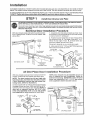
TO PREVENT DAMAGE TO LIG HTWEIGHTGARAGE DOORS, ALWAYS REINFORCE THE INSIDE OF DOOR-BOTH VERTICALLY AND HORIZONTALLYMWITH
2x4 BOARDS OR ANGLE IRON.
Horizontal brace should be at least 6 feet tong Verticat brace should cover height of top panel. Reinforcement
hardware is not supplied (See No t Below.) FASTEN SECURELY AS SHOWN BEFORE INSTALLING DOOR
BRACKET AND PLATE_
Sectional
Door installation
With door closed, locate and markthe vertical centerline of garage door. Extend line onto header wail
above door.
1. Assemble door bracket and plate as shown Center bracket on vertical guideline (or up to one foot left
or right of center if necessary)
2o Position bracket assembly on face of door within
the following limits: A. Top edge of bracket 2" to 4"
below the top edge of door B. Directly below any
structural support across top of door.
Header
:kel
L
Placement
Header
Wall
Vertical
Center-Line
depends
on your particular
needs
3. Mark and drill 5/! 6"TOP and BOTTOM fastening
holes Secure bracket as shown
I
Door Bracket
P{ate Assy
Procedure
5/16"-18x2-1/2"
Carriage Bolt
&
Door
Bracket
._
Door Bracket
Plate
TOp of Door
Lock
Washer
SECTIONAL
Door
Arm
DOOR
5/16"
Board for
Lightweight
Doors
All One-Piece
Door
Inside Edge
of Door or
Reinforcement
Board
installation
With door closed, locate and mark vertical centerline
of door,, Extend line onto header wall above door
Nut
5/16"-18
Procedure
NOTE: Door bracket
may be installed
on face of
door if required for your installation.
(Refer to
dotted line drawing).
HOWEVER,
drill 3/16"pilot
holes and substitute
5/16"
x t-1/2"
lag screws
(not supplied)
to fasten bracket to door_
NOTE: The door bracket
has left and right side
fastening
holes. Assemble
door bracket and plate
if your installation
requires
top and bottom
fastening
holes. (Refer to illustration).
Center bracket (with or without plate as required) on
top edge of door as shown Mark and dri]I two 5/16"
fastening
holes and secure door bracket. NOTE: if
door has no exposed
framing,
drill 3/16"
pilot
holes and substitute
5/16" x 1-1/2" lag screws
(not supplied)
to fasten bracket to top of door°
Lock Washer
5/16"
Door,
Top Edge
of Door
(Outside)
5t16"-!8
Bracket
Plate
Face of DOOr
installation
Vertical
Center
Line
- (Optiona!)
Carriage Boil
5/16"-t8x2-1/2'"
ONE PIECE DOOR
lO
Door Brackel
Plate
(Optional)
nstanUation
S=_E
P
2
Position
& Install
THE HEADER BRACKET
MUST BE RIGIDLY FASTENED
WALL OR CEILING
WITH 2x4 IF NECESSARY,,
HEADER
WALL OR CEILING.,
SECTIONAL
DOOR
CURVED TRACK
REINFORCE
ONE-PIECE
DOOR
HORIZONTAL
TRACK
JAMB HARDWARE
Ceiling
Optional Quick Turn Brackets are designed for low
headroom installations They replace top brackets
and roilers on the garage door, thereby lowering the
high point of door travel Installation
instructions
are
contained in the accessory carton
Header
Bracket
Header
Bracket
Track
Highest Point
of Travel
Position bracket as shown (bottom edge of bracket
on horizontal line) Mark either top and bottom or left
and right bracket holes Drilt 3/I6"
pilot holes and
fasten bracket
Door
ack
./
1
F_
TO THE
Bracket
INSTALLATION
SECTIONAL
DOOR AND
l-PIECE
DOOR WITH TRACK
Locate height for header bracket by opening door to
highest point of travel as shown. Draw a horizontal
line on header wall 2" above high point This height
provides travel clearance for top edge of door
When headroom is not sufficient
for 2" clearance,
bottom edge of bracket may be placed parallel to the
hig!_ point of travel, or bracket may be attached to
ceiling
//_
Header
/"
/i_
Lag Screws
5/16"-18x1"7/8'_
Header
Bracket
J
,/
/
1-PIECE
INSTALLATION
DOOR WITHOUT
ONE-PIECE
DOOR
NO TRACK
PIVOT HARDWARE
Locate height for header bracket by opening door to
highest point of travel as shown, Measure distance
from top of door to floor. Subtract
actual height of
door Add 8" to the remainder
See example below,
TRACK
If the total number of inches exceeds the height
available in your garage, use the maximum
height
possible
On finished ceilings, do not position the
bracket closer than 1/2" from ceiling,,
ONE+PIECE
DOOR
NO TRACK
-JAMB HARDWARE
Measuring from top of door, draw a horizontal line on
the header wall at the determined
height
Position
bottom edge of header bracket on horizontal
Hne,
centering
bracket on vertical line. Mark either top
and bottom or left and right hole& Drill 3/16" pilot
holes and fasten with 5/16" x 1+7/8 '' lag screws as
shown above
EXAMPLE
Distance from top of door (at
highest point of travel) to floor
Actual height of door
Remainder
Add
Bracket
1t
height
on header
wall
92"
-88"
4"
+ 8"
=12"
nstamlation
STEP 3
Clevis Pin
5/t6"'x2-3/4-
He8
Bracket
Attach
_!1j
Tee Rail to Header
PROCEDURE:
Position opener chassis on garage
floor below door' and header brackets. Use packing
material base to protect cover NOTE: To enable
Tee rail to clear sectional
door springs,
it may be
necessary
to lift the chassis
onto a temporary
support.
CAUTION: Chassis must either be secured to support or held firmly in place by another person.
Raise Tee rail until cable pulley and header brackets
come together.. Align bracket holes and join with
clevis pin as shown Insert and spread cotter pin to
secure.
Cotter
Pin
Cable
Pulley"
B_acket
Packing
Bracket
Materiat
STE P 4
TO PREVENT
DAMAGE
TO ALL
OPENER ON THE DOOR..
po,,io. Opener Chassis
LIGHTWEIGHT
DOORS,
AND
DOORS
WITH
WINDOWS,
DO NOT RESTTHE
ONE-PRECE DOOR
WITH NO- TRACK
INSTALLATnON
SECTIONAL
and ONE-PIECE
DOOR WiTH TRACK
nN STA LL&_ II0 N
NOTE: A 2x4 is convenient
for setting an ideal
door-to-Tee
rail distance,
it is not necessary
where headroom
is insufficient°
PROCEDURE:
Measure the distance from floor to
top of door (in fully open position and paratlei to
floor)
PROCEDURE:
Raise the opener chassis onto a
stepladder.
Open the garage door Place a 2x4 on
edge on top section of door directly
above door
bracket.
Rest Tee rail on 2x4
Using a stepladder
as a support,
raise the opener
chassis to the same distance from the floor (chassis
witt have a slight angle as shown)
Tee Rail
The top of the door should be level with the top of the
opener For maximum efficiency, do not position the
opener chassis more than 2 inches above this poinL
Header
2x4
Top o! Opener
I
Door
Door
Bracket
I
I
i
I
Ste
I
Equat
--_ Distance
from
Floor
I
--4
I
I
I
I
t
12
UnstaIlation
STEP 5
Hang
Opener
Chassis
THE OPENER CHASSIS MUST BE ATTACHED TO A
STRUCTURAL
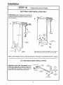
SUPPORT OF THE GARAGE Three
representative
installations
are shown_Yours may be
different, Hanging brackets should be angled to provide rigid support,
PROCEDURE:
On EACH side of opener measure
the distance from chassis to structural
support,,
Lag Screws
5/16"xt-7/8"'
Cut both pieces of the hanging bracket to required
lengths. Flatten one end of each bracket and bend or
twist to fit fastening angles_ DO NOT BEND AT BRACKET HOLES Drill 3/16" pilot holes in structural support. Fasten flattened
ends of brackets to support
as shown,,
Lift opener and fasten to hanging bracket as shown,,
Checkto
make su re Tee rail is centered
over door
bracket.
Close the garage door. If door hits rail,
raise header bracket.
REMOVE 2x4o
Grease rail surfaces
grease is supplied,,
on which trolley slides_ A tube of
Bracket
(Not Supplied)
Finished
Ceiling
Screws
5/16"xl-7t8"
_TE
P
_
Attach
Emergency
Release
Rope & Handle
USE EMERGENCY
RELEASE ONLY TO DISENGAGE
TROLLEY.
DO NOT
USE
RED
EMERGENCY
RELEASE
ROPE AND HAN_
DLE TO PULL DOOR OPEN OR CLOSED_
Overhand
Knot
PROCEDURE:
Thread one end of rope through hole
in top of red handle so 'NOTICE' reads right side u15
as shown_ Secure with an overhand knot NOTE: Knot
should be at least I inch from end of rope to prevent slipping,
Thread
other end of rope through
hole in release arm of outer trolley, Adjust rope length
so that handle is 6 feet above the floor,, Secure with
an overhand knot as above,,
Trolley
Release Arm
Rope_
NOTE: If it is necessaryto
cut rope, heat seal cut
end with a match
or lighter
to prevent fraying
and/or
raveling,
_-
13
overhand
Knot
Top
_nsta_lation
Flange
INSTALL
"WALL CONTROL
(OR ADDITIONAL
PUSH BUTTONS)
OUTOFTHE
REACH OFCHILDREN,_ DO NOT ALLOW CHILDREN
TO OPERATE WALL
CONTROL
OR TRANSMITTER_
SERIOUS
PERSONAL
INJURY
FROM A CLOSING GARAGE DOOR MAY RESULT FROM ANY
MISUSE OF OPENER°
FASTEN THE CAUTION
LABEL ON THE WALL
NEAR THE WALL CONTROL
AS A REMINDER
OF SAFE OPERATING
PROCEDURES,.
i
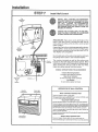
PROCEDURE:
There are 4 screw terminals on the
back of the Wall Control
Connect the bell wire by
color; yellow to yellow, white to white, red to red and
black to black,
Wall
Control
Terminals
r
Bo|tom
Installation
Flange
o
Fasten Wail Control to an inside garage wall, as shown,
with the 8ABxl "sheet metal screws provided. A convenient place is beside the service door and OUT OF
THE REACH OF CHILDREN
Run the belt wire up the wall and across the ceiling
the garage door opener_ Use insulated staples
O
Opener
Terminats
O
The receiver terminals
as well as the antenna are
located on the right side panel of the opener., Bend
antenna wire down until it is parallel to chassis panef
Then connect the wire by color to the red, white,
black and yeltow opener terminal screws..
WIRING
INSTRUCTIONS
Infrared
FOR ACCESSORIES
Reversing
System:
To white & black opener terminals
Open Door Indicator:
C:3
Right Side
Panel
of
Opener
To white & orange
Antenna
opener
Key Switch:
To red & white opener
OPERATION
Vacation
Push Button
to
OF WALL
terminals
terminals
CONTROL
Work Light
Push Button
WALL
Press and release
CONTROL
PUSH
BUTTON
to open or clQse door
Press and release again to REVERSE door during
or to STOP door during OPENING
cycle
VACATION
Activate
Vacation
feature
PUSH
CLOSING
cycle
BUTTON
only when
door is In closed
position,
Press and release, Push button light will turn ON The Vacation feature was designed
to prevent operation of door from the transmitter
and aEiow door to travel in the UP direction
ONLY from the Wall Con _
trol push button (press and release) and Key Switch accessory
Press and release again. Push button
return to normal operation
A power failure
feature
to turn
Wall Control
Push Button
of more
OFF,
WORK
Press and release
Press and release
14
than 30 seconds
LIGHT
Opener
again
light witl turn OFE Opener
PUSH
will cause the vacation
BUTTON
tight will turn on and remain
Opener
will
light wilt return
on
to normal operation.
0nstatUation
STEP 8
Connect
Electric
Power
I
TO AVOID SERIOUS PERSONAL INJURY FROM ENTANGLEMENT, REMOVE ALL ROPES CON NECTEDTO THE I
GARAGE DOOR BEFORE OPERATING DOOR OPENER_
REMOVE EXISTING GARAGE DOOR LOCKS OR USE A WOOD SCREW OR NAIL TO MAKE THE_,_ INOPERATIVE,
INSTALLATION AND WIRING MUST BE IN COMPLIANCE WITH LOCAL BUILDING AND ELECTRICAL CODES.
OPERATION AT OTHER THAN !2OV 6OHz WILL CAUSE OPENER MALFUNCTION
AND DAMAGE,
IF LOCAL ELECTRICAL CODES DO NOT REQUI RE
PER MAN ENT WIRING: Insert the 3-prong plug into a
3-hole receptacle. UNIT MUST BE GROUNDED
DO
NOT USE A 2-WIRE ADAPTER,
IF LOCAL CODES REQUIRE
Refer to illustration,
PERMANENTWIRING:
PROCEDURE:
Make connection
through
diameter hole in top of opener chassis,
1o Remove opener
cover screws,
2,, Remove
attached
chassis
7/8
cover by removing
3-prong
inch
Ground
the 4
Tab
Ground
Screw
cord,
3. Connect black (line) wire to black wire on terminal
block; white (neutral) wire to white terminal wire; green
(ground) wire to green ground screw
I Wire
CAUTION:
BE SURE UNIT IS GROUNDED
ACCORDING
TO LOCAL CODE
_,White
Wire
STEP 9
i. to,
Lights
andLenses
PROCEDURE:
Install a 75 watt maximum light bulb
in each socket as shown The lights turn on automatF
calty when opener starts. After 4-I/2 minutes they
will turn off, Lights will REMAIN ON when Work Light
push button on Wail Control is pressed,
Lens
Guide
IMPORTANT
NOTE: If the lights in your garage
door opener do not work, it may NOT be the fault of
the opener° Some short-neck
butbs_ because
of
their shape, do not make contact
with the socket
base tab. Use standard.neck
bulbs°
Lens Tab
INSTALLING
LENSES:
Slide lenses into the fens
guides as shown. Snap bottom tabs into lens slots.
(The force and limit adjustment settings are located
on side panels behind lenses),
Lens
Slot
NOTE: FOR CONVENIENCE,
LENSES MAY BE INSTALLED AFTER ADJUSTMENT,
STEP 3, PAGE 20_
15
instal|ation
:
ST_
_
P
:
,rrr_
.......
...................
"I 0
..........:r,, ,,
,hr
Connect
SECTIONAL
.............
DOOR INSTALLATION
PROCEDURE:
Fasten straight door arm section to
trolley and wedge door arm section to door bracket,
as shown (A)Insert and spread a cotter pin to secure
each connection_
A
!'_
Door Arm to Trolley
.................
ONLY
B
_ .___
,/II
,ov,s ,n
Lock
Nut
Washers
5/!6"q8
Do,,,
/1
5/16"
I_1--- Straight
Door
Bracket
Bring the door arm sections together. Find a pair of
holes that line up and join sections as shown (B),
INSTALLATION
FOR SECTIONAL
DOOR
IS COMPLETE.
ALL ONE-PIECE
PROCEED
DOOR
ASSEMBLE DOOR ARM PROCEDURE: Fasten
straight and wedge door arm sections together to
their longest possible length. With door.closed, con_
nect straight door arm section to door bracket as
shown, insert and spread cotter pin to secure.
TO ADJUSTMENT
STEP
1 , PAGE 18.
iNSTALLATiONS
Cotter
Pin --I
Clevis
Pin
Door
Wed_
Door
Straight
Door Arm
Lock Washer
5/16"
Screws
5/16"-18
16
x 7/8"
nstam ation
STE P 11
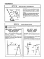
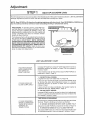
Adj.,,Limits
(All One-Piece
Doors
Only)
CAUTION:
To prevent damage to garage doors,
the opener limits must be adjusted
on ALL ONEPIECE DOORS,
Limit Adjustment
settings
regulate
which door will stop when moving
the points at
up or down.
Repeated operation of the opener during adjustment
may cause the motor to overheat and shut off. Simply
wait 15 minutes and continue adjustments,
Limit adjustment
screws are located on the left side
panel of the openeras shown Increase limits by turning screws in direction
shown on label.. Decrease
limits by turning screws in opposite direction._
Left Side
Panel
Limit
Adjustment
Screws
Adjustment
The following illustration shows the position of the door arm and trolfeywhen
and when the door is closed (dotted line drawing),
Label
the door is open (solid line drawing),
Fully Closed
Trolley
!
1
L
I
Door
Arm
Bracket
Closed
Door
Door
Arm
C
i
t
ADJUSTMENT
PROCEDURE
- OPEN
PROCEDURES
PROCEDURE
DOOR ADJUSTMENT
- CLOSED
DOOR
ADJUSTMENT
DECREASE the U P limit by turning the UP Hmit adjust _
ment screw counterclockwise
8 complete turns
DECREASE the DOWN limit by turning the DOWN
limit adjustment
screw clockwise 4 complete
turns
Press Wall Control push button., Trolley will travel ta
full open position..
Manually raise garage door to open position (paraF
lel to floor) and lift door arm to trolley, The arm should
touch trolley just in back of door arm connector hole
as shown in solid line drawing if the arm does not
extend far enough, make further DECREASED
limit
adjustment,, One full turn equals 2 inches of door
travel,
Press Wall Control push button.
full closed position,
Trolley
will travel
to
Manually close garage door and lift door arm to the
trottey, Arm should touch trolley just ahead of door
arm connector hole as shown in dotted line drawing,,
If arm is behind the connector
hole, make further
DECREASED limit adjustment,
One full turn equals 2
inches of door travel.
CONNECT DOOR ARM TO TROLLEY PROCEDURE: With door closed,join wedge door arm to connector hole in
trolley with the remaining clevis pin, Secure with a cotter pin. NOTE: It may be necessary to lift door slightly to
make connection.
Run the opener through a complete travel cycle if door has a slight 'downward' slant in full open position, turn the
UP limit adjustment screw counterclockwise to decrease travel until door is paraiiel to floor
17
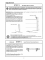
Adjustment
STEP 1
,,
,, ,, _ ,, .......
,,,,
......
Adjust
UP and DOWN
Limits
,,,,,,,,,,
The limit adjustment screws are located on the left side panel of the opener chassis
settings regulate the points at which the door will stop when moving up or down
as shown
LI MITADJUSTMENT
NOTE: Door STOPS in U P direction
if anything
interferes
with door travel_ Door' REVERSES
tion if anything interferes with door travel (including
binding or unbalanced
doors).
PROCEDURE:
To operate opener, press Wall Con_
trot Push Button or transmitter
push button. Run the
opener through a COMPLETE TRAVEL CYCLE No
adjustments
are needed when the door- opens and
closes completely
and does not reverse unintentionally in down direction.
ilo
o
The following chart outlines adjustment
procedures.
Run opener through a COMPLETE TRAVEL CYCLE
AFTER EACH ADJUSTMENT.
NOTE: REPEATED
OPERATION
OFTH E OPEN ER DURING ADJUSTMENT PROCEDURES
MAY CAUSE THE MOTOR
TO OVERHEATAND
SHUTOFFo
SIMPLY WAtT 15
MINUTES
AND TRY AGAIN° Read the chart carefully before proceeding to Step 2, Pg 19 Use a screwdriver to make limit adjustments
Limit
Adjustment
Screws
Adjustment
LIMIT
IF DOOR DOES NOT
OPEN COMPLETELY
BUT OPENS AT
LEAST FIVE FEET
ADJUSTMENT
Label
CHART
Increase UP travel by turning UP LIMIT adjustment
clockwise
direction
as shown on label One turn
inches of travel
if door doesn't open at least 5 feet, adjust OPEN
explained in Step 2, Page 19
1o ON SECTIONAL
DOORS:
Lengthen the door arm (See Step
IF DOOR DOES NOT
CLOSE COMPLETELY
in DOWN direc-
screw in
equals 2
FORCE
as
10, Page 16),
If door arm is at maximum length, increase the DOWN travel
by turning the down limit adjustment
screw in a counter
clockwise direction
as shown on label, One turn equals 2
inches of travel,
If door still will not close completely,
the header
positioned
too high, Repeat Step 2, Page 1t
2o ON ONE-PIECE
DOORS:
bracket
is
Increase DOWN travel by turning tile down limit adjustment
screw in a counterclockwise
direction as shown on label, One
turn equals 2 inches of travel.,
TEST
IF DOOR REVERSES
WHEN CLOSING AND
THERE IS NO INTERFERENCE TO
TRAVEL CYCLE
DOOR
FOR BINDING
Pull emergency release handle and manually open and close
the door, tf door is binding, call a door serviceman
1. IF OPENER REVERSES BEFORE DOOR CLOSES FULLY:
Adjust the CLOSE FORCE as explained
in Step 2, Page 19
2,, 1FOPENER REVERSES IN FULLY CLOSED POSITION:
Decrease DOWN travel Turn the down limit adjustment screw
in clockwise direction. One turn equals 2 inches of travel
18
STEP 2
DO NOT USE FORCE ADJUSTMENTS
EXCESSIVE
FORCE WILLINTERFERE
OR DAMAGE THE GARAGE DOOR.
Adjust
TO COMPENSATE
WITH THE PROPER
FOR A BINDING
OR STICKING
GARAGE
DOOR,
OPERATION
OFTHE SAFETY REVERSE SYSTEM
Force Adjustment
Controls are located on right side
panel of the opener chassis,, FORCE ADJUSTMENT
settings regulate the amount of power required to
open and close the door
NOTE: Door STOPS in UP direction
if anything
interferes
with door travel° Door REVERSES
in
DOWN direction
if anything
interferes with door
travel (including
binding
or unbalanced
doors)°
Controls
If force adjustments
are set too light, door travel may
be interrupted
by nuisance reversals in the DOWN
direction and stops in the UP direction
As weather
conditions
can affect door movement,
occasional
adjustment
may be needed
The maximum force adjustment range is 260 degrees,
about 3/4 of a complete turn, Do not force controls
beyond that point Turn force adjustment
controls
with a screwdriver,
Adjustmenl
Label
FORCE
ADJUSTMENT
CHART
IF DOOR DOESN'T
OPEN AT LEAST 5 FT:
Increase UP (OPEN) FORCE by turning control in a clockwise direction as shown on label Make 10 degree turn adjustments until door opens completely,
Readjust UP LIMIT if
necessary. After each adjustment,
run the opener through a
complete travel cycle
IF DOOR REVERSES
DURING THE DOWN
(CLOSE) CYCLE:
increase
DOWN (CLOSE) FORCE by turning control in a
clockwise direction as shown on label, Make 10 degree turn
adjustments
until door completes the close cycle, After each
adjustment,
run opener through a complete travel cycle_
TEST DOWN
(CLOSE)
FORCE:
Grasp the door handle or door bottom when door is about
halfway tiirough DOWN (CLOSE) TRAVEL,. The door should
reverse
If the door is hard to hold or doesn't reverse, decrease the DOWN (CLOSE) FORCE by turning the control in a
counter clockwise
direction
Make 10 degree turn adjustments until the door reverses normally, After each adjustment, run the opener through a complete travel cycle,
19
THE SAFETY REVERSE SYSTEM TEST iS IMPORTANT.
THE GARAGE DOOR MUSTREVERSE
ON CONTACT
WITH A ON E 1NC H OBSTAC LE PLACED ON TH E FLOOR. FAILU RE TO PROPE R LY ADJ UST TH E OPE N E R MAY
RESULT IN SERIOUS PERSONAL
INJURY FROM A CLOSING
GARAGE DOOR° REPEAT THE TEST AT LEAST
ONCE A YEAR AND MAKE ANY NEEDED
ADJUSTMENTS,
PROCEDURE:
Place a 1-inch obstacle
on the floor
direction,. The door must reverse on the obstruction
under
the garage
if a SECTIONAL
door STOPS on the obstruction,
lenghthen door arm (Step 10, Page 16) until the door
reverses in DOWN direction._
door
Operate
SECTIONAL
the door in the DOWN
DOOR
If a ONE-PIECE
door- stops on obstruction,
door is
not traveling far enough in DOWN direction Increase
the DOWN limit by turning the DOWN limit adjustmentscrewcounter-clockwise
1/4 turn REPEATTEST,,
When the door reverses on the 1-inch obstruction,
remove obstruction
and run opener through a complete travel cycle, Door must not reverse in closed
position, if it does, repeat Adjustment Steps 2 and 3
ONE-PIECE
DOOR
I
/
f
ch ObstruCtion
REPEAT
1.
2.
3.
4,
ADJUSTMENT
STEP
3 AFTER:
EACH ADJUSTMENT
OF DOOR
ANY REPAIR OR ADJUSTMENT
ANY REPAIR OR BUCKLING
OF
ANY REPAIR OR ADJUSTMENT
(Optional)
STEP
ARNI LENGTH,
CLOSE FORCE OR DOWN LIM|T
OFTHE GARAGE
DOOR (INCLUDING
SPRINGS
THE GARAGE FLOOR
OF THE GARAGE DOOR OPENER
4"
install
The INFRARED REVERSING SENSOR provides an
ADDITIONAL
measure of safety against small children being caught u nder a garage door, tt uses an invis _
ibte beam which, when broken by an obstruction,
causes a closing door to open or prevents an open
door from closing
After the
installed
SENSOR
included
garage door opener has beeh completely
and adjusted, the INFRARED REVERSING
accessory car] be installed, Instructions
are
with this optional device
CAUTION: The Infrared
Reversing Sensor
be in effect when Vacation
Light is ON,
will not
2O
tnfrared
Reversing
AND
HARDWARE}
System
Operation
of Your Opener
CAUTION:
® START B Y READING THE SAFETY RULES ON PAGE 3.
e READ THE OPERATING INSTRUCTIONS
ON THIS PAGE CAREFULLY°
e DO NOT PERMIT CHILDREN TO PLAY IN AREA OF DOOR.
e OPERATE ONLY WHEN OPENER IS PROPERLYADJUSTEDAND
DOOR IS IN SIGHTAND
FREE OF OBSTRUCTION°
THE SAFETY REVERSE
SYSTEM IS IMPORTANT
(SEE PAGE 20). GARAGE DOOR MUSTREVERSE
ON CONTACTWITH
A ON E_iNCH OBSTACLE
PLACED ON THE FLOOR. FAILURE TO PROPERLYADJUSTOPENER
MAY
RESULT IN SERIOUS PERSONAL
INJURY FROM A CLOSING
GARAGE DOOR° REPEATTHE
TEST AT LEAST
ONCE A YEAR AND MAKE NEEDED
ADJUSTMENTS°
USING
THE
OPENER
Your garage
door opener
can be activated
1o Pressing
the transmitter
push button.
2. Pressing the Wall Control
3.. By turning the Key Switch
by any of the following
Hold the button
push buttons°
(if you have installed
to move,
this accessory),,
WHEN EITHER THE WALL CONTROL
OR TRANSMITTER
FOLLOWING
WILt. OCCUR (Vacation
Light OFF):
1.. If open, the door wilt close,
methods:
down until door starts
PUSH
BUTTONS
ARE PRESSED,
ONE
OF THE
if ctosed, the door will open.
2.. if closing, the door will reverse.
3.. If opening, the door will stop (allowing
space for entry
and exit of pets and for fresh air)..
4, tf the door has been stopped in a partially open position (refer to 3o above), it will close,.
5_ if an obstruction
is encountered
while closing, the door wilt reverse..
6. If an obstruction
is encountered
7o The optional Infrared Reversing
when the IR beam is obstructed
while opening,
the door will stop..
Sensor, if installed, will signal the opener
and prevent an open door from closing.
to reverse the door in the closing cycle
It has no effect in the opening cycle..
THE LIGHTS
When the opener is activated, lights will turn on_ They will turn off automatically
watts maximum.. When Work Light is ON, the lights will remain on.
OPENING
THE
after 4-1/2
minutes,
BULB SIZE-75
DOOR MANUALLY
The door can be operated
manually by disconnecting
it from the opener. Simply pull down sharply on the red
emergency
release handle.. The door may now be lifted manually_ DO NOT USE EM ERGE NCY ROPE AND HANDLE
TO PULL TH E DO0 R OPEN OR CLOSED. To automatically
reconnect the door to the open er, press the Wall Control
push button
CARE
OFTHEOPENER
When properly installed, your opener wilt perform efficiently with a minimum of maintenance.
replace a light bulb or change a transmitter
battery from time to time° A 9-Volt AIkaline battery
is available at Sears..
The opener does not require
oiled yearly.,
additional
lubrication
- HOWEVER
- the door rollers,
Most complaints of unsatisfactory
opener operation can be traced to problems with
intended to correct problems caused by an unbalanced
or binding door, broken door
When operating the door manually, a properly balanced door will stay in any point
soley by its springs. If you encounter
any difficulty when operating door manually,
bearings
You will be required to
is the most reliable, and
and hinges
should
be
the door itself. The opener is not
springs or fautty door hardware.
of travel while being supported
call a garage door serviceman.
RADIO CONTROLS
Refer to pages 22 and 23 for complete details°
LIMIT AND FORCE ADJUSTMENTS
Refer to pages 18 and 19 for limit and force adjustmentsThese adjustments must be checked and properlyset when opener
is installed_Weather conditions may cause minor changes in door operation requiring some change in adjustments,
particularly during the first year of operation. Only a screwdriver is required. Follow instructions carefully_
CHAIN TENSION ADJUSTMENT
After installation of opener and adjustment of forces and limits, chain may appear loose,. This is normal. TO CHECK
CHAIN TENSION: disconnect the trolley by pulling red emergency handle_ If chain returns to position described in
Step 5, Page 9, DO NOT make further adjustments,
21
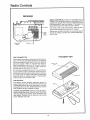
Radio Controls
RECEIVER
RADIO CONTROLS
consist of a transmitter
and a
receiver° The transmitter
sends a coded signal from
outside the garage. The receiver is fastened to the
right side panel of the door opener
It receives the
transmitted
signal and starts the door opener.
-Terminals
The signal code is set at the factory
Page 23 describes code changing procedures,
if required..
Self service of radio controls is not recommended,
if
service is needed, contact your nearest Sears Service Center.
Code
Switch
Block
/
Right Side
Panel
Anger
TRANSr_tITTER
THE TRANSMITTER
The portable transmitter
may be secured toa car sun
visor with the clip provided
Additional
transmitters
can be purchased
at any time for use in all vehicles
using the garage
(Refer to Accessories,
Page 5).
New transmitters must be set to the same code as
original transmitter
and receiver
Follow code setting procedures
described
on Page 23
Battery Test
Light
A 9-volt battery supplies the power The transmitter is
equipped with a battery check light When the trans mitter push button is pressed, light will glow if battery
has power (and the opener will operate),. When light
does not come on, replace battery., if transmission
range lessens, check battery light,
THE
Push BuUon
BATTERY
The battery
should produce
adequate
power for
approximately
one year:, Avoid the inconvenience
of
unexpected
battery failure by replacing it annually,
preferably
before winter.. Alkaline batteries are the
most reliable and are available at Sears..
Battery
TO REPLACE BATTERY: Remove visor clip and unfasten connecting
screw, Remove top of transmitter
case and discard old battery., Snap connector
onto
new battery, Replace top of case and connectiqg
screw. Replace visor clip
Visor
22
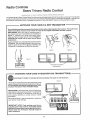
Radio ControlJs
Sears Td nanj Radio ControJ
Manutactured
ut_der ! or more
o! the
lollowing
U S. patenls:
3 445 848;
3 906,348;
and 4 037
20!
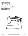
The coded signal in Sears Trinary Radio Controls can be changed easily without the aid of a serviceman, The only tool
needed is a flat blade screwdriver, Choose your own code by changing position of switches numbered 1 through 9 on
the receiver code switch block., Changing the position of only one switch makes an entirely different code,
............
--
MATCHING
YOUR CODE
IN A NEW
TRANSMITTER
The original transmitter
is preset at the factory to the same coded
NEW transmitters
must be set to match the code in the original
PROCEDURE:
With visor clip off, remove screw in
the original and new transmitter(s)
as illustrated
in
Figure 1. Carefully
turn ca_es over (push button
sides up), Remove case tops as shown in Figure 2.
CAUTION:
Be careful not to move circuit
board
components.
Place transmitter circuit boards side by side as shown
in Figure 3. Set the code switches in the new transmitter to match those in the original transmitter.
Use
a fingernail
or screwdriver
to slide the switches.,
signal as the receiver. The code in any
transmitter
and the receiver.
Figure
Figure
.............
Figure
I
2
3
)
Transmitter
Code
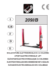
CHANGING
DISCONNECT
YOUR CODE
POWER
TO OPENER
IN RECEIVER
BEFORE
CHANGING
AND
THE
Circuil
Board
Switches
TRANSMITTER(S)
CODE
IN THE
Figure
RECEIVER°
4
The receiver is fastened to the right side panel of the
opener chassis. Code switches are shown in Figure 4,
IFYOUCHANGETHE
CODE tN YOUR RECEIVER, ALSO
CHANGE THE CODE IN YOUR TRANSMITTER(S).
PROCEDURE:
Hold transmitter
circuit board alongside receiver code switches as shown To change the
code, use a fingernaif
or screwdriver.
Slide one or
more receiver switches
to a plus, minus or center
(0) position
Set code switches in the transmitter(s)
to match the
new receiver code setting&
Code
Switch
N
IMPORTANT
NOTE: Code settings must be exactly the same in the receiver, transmitter
and all
additional
transmitters
used to operate the door.
Please keep this instruction
manual
handy for
future reference.
,,, ,,
_;
....... ;:: ..............
,t,,_
RED
* ',,,'"",' ',....
23
WriT
BLK
ORN
N
YEL
.................
OPENERDOESN'T
DOOR OPENS
ACTIVATE
1. Have you removed
LIGHTS
1 Won't turn OFF? Check
2 Won't turn ON? Check
4., Are wiring connections
correct? Refer to Step 7,
Page 14..
5, Repeated operation may have tripped the overload
protector in the motor. Wait 15 minutes. Try again..
1.. Check
2 Change
RANGE
t. Replace
3 Vacation
in car
DOOR DOESN'T
1. ts something
the door?
2. Limits may need adjustment.
See Pg.. 18
3. Force may need adjustment
See Pg, 19
4 Door will not ciose while in Vacation mode..
THE NEED
CONDITIONS
FOR OCCASIONAL
IN PARTICULAR
Transmitter
ADJUSTMENT
CAN AFFECT
light is ON.
FOR NO APPARENT
Pull red emergency
release handle Operate the
door manually. Is it balanced? Binding? If service is
needed call a garage door serviceman
2
Force adjustment
OF FORCE AND LIMIT
DOOR MOVEMENT_
may be needed
CONTROLS
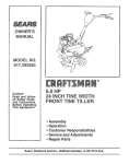
_LSla
^ _
(_TPI,_gv
i
9v_L..
IS NORMAL.
_
C) TP3-6,2V
cl
TP2-GND
..L
,OtpF T
_ O_
.,/_
L_I_
S2-CODE SELECT
Dl
i
'c
t Itl_l tlTI t h h:lhj +................
_o7c5B
33_L
_t41s16171m_191
_
e
_L 04
q
_
I=1 1=3 !_5 b9 b7_*62V
b2 _ t_6 l_B OUT11!__.,.,__,_
_c
UI
114
'
u
• _
TP4 R2 _ J-C2
u_ _._,._
"T-t00
....
_
VC
vsslll3 [I
112 Is
I
N_,
"
t
j
J
0
TPS_
BAS_
|
DRIVE
REASON
t
Schematic
BI_
Referto
See Pg 19
3 Check for proper alignment of Infrared Reversing
Sensor (if you have installed this accessory).
4 Clear ice and snow from gar age floor area where garage door closes
OPEN OR CLOSE COMPLETELY
obstructing
Have you set the code?
DOOR REVERSES
3, Metal garage door, foil-backed insulation or metal
siding will reduce range
4 Antenna on side panel of opener must be fully
extended downwar&
BUT NOT
the battery
2 New transmitter'?
Page 23.
INSUFFICIENT
location
Work Light. is it ON?
light bulbs,
DOOR OPERATES FROM PUSH BUTTON
FROM TRANSMITTER
battery.
transmitter
BY ITSELF
1 Neighborwith
a Sears opener using the same code?
Change your code..
all door locks and bolts?
2 Does the opener have electric power? Check wait
switch, fuse, etc.
3. is there a broken wire between Walt Control and
opener? Check under staples, (A positive check
can be made by temporarily instalb_g another wire)
TRANSMITTER
AND CLOSES
5SK
i_" ! •_41I
--_5._ :
2/K L__
_! C
24
_Lcel
T391
_._
C5
I
t
WEATHER
F
I_,i _
=9
g
•
I
25
Repair Parts
RAI L ASSEMBLY
PARTS LIST
NQ_
KEY
1
2
3
4
5
6
7
8
NO,,
PART
DESCRIPTION
1A995
41 B2617
4t B2771
12A197
28313
t83893
41 82616
41 C2735
Master link kit
Outer trolley
Inner trot{ey
Chain retainer
bracket
Tee rail-center
section
Tee raiJ-end section (each)
Cable pulley bracket assy(each)
Chain and cabie
i
NOT SHOWN
41A2814
INSTALLATION
Rail assy
illustrated
hardware kit (includes
on Page 4)
hardware
PARTS LIST
, i,, ,,,,,,,
NO,.
KEY
1
2
3
4
5
6
7
8
9
10
tt
NO.
PART
DESCRIPTION
41D2736
10A13
41A2830
29C121_2
41A2828
2t9A319
41A2829
128374
12B380
178B32
178B33
Wall control assy
9 volt battery (available
at Soars)
Transmitter
case, cover and screw
Transmitter
visor ctip
Emergency
rope and handle assy
4-Strand belt wire
Header bracket
plus cotter
Door bracket
Door bracket pIate
Wedge door arm section
Straight door arm section
assy
6
"x.
pin and clevis
7
NOT SHOWN
41A2815
Installation
hardware
bag (includes
hardware
trated on Page 4)
26
illus-
--11
Repair
Chassis
Parts
Assembmy Parts List
22
5
12
19
18
13
16
KEY
NOr
PART
NO,
31C290
4IA2827
3
41A28t7
4
5
6
41 B2991
41C2725
41A3063
4tA3073
DESCRIPTION
1
Sprocket cover
Gear and sprocket assy
Complete with:
Spring washer
Thrust washer
Retaining ring
Bearing plate
Roll pins (2)
Drive gear
Worm gear
Helical gear w/retainer
Grease
Drive/worm gear kit w/grease
Roll pins (2)
Line cord
Wire harness assy w/pIug
Receiver logic board assy.
Logic board
End panel w/all labets
Light socket (1}
End panel wiali labels
KEY
NO.
PART
NO.
8
9
10
11
t2
13
14
15
16
t 7
18
t 9
20
21
22
175B88
108D30-1
30B363
12A373
1A25t0
41A2821
41C2740
41A2818
41 D3013
41C3005
41A3027
4tA2826
4tA2822
41A3074
t2B350
DESCRIPTION
]
Light socket (each)
Lens (each)
Capacitor
Capacitor bracket
Terminal Mock w/screws
Motor assy. w/rolt pin
Cover w/all labels
Helical gear and retainer w/grease
Limit switch assy
RPM sensor assembly
Motor bracket and bearing assy.
Shaft beadng kit
Interrupter cup assy
End panel
Hanging brackets
NOT SHOWN
114A895
41A2825
27
Owners manual
Chassis assy hardware kit (includes screws
not designated
by number in illustration)
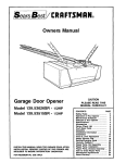
Owners
tiVtlanua8
®
=
.............. ,......
,i i,, ,i ,,, L
HOW
Garage
Door
Opener
ModeU
139,535006
,,
TO ORDER
REPAIR
PARTS
Now that you have purchased
your Sears Garage Door Opener, should a
need ever exist for repair parts or-service, simply contact any Sears Service
Center and most Sears, Roebuck and Co stores
Be sure to provide atl
pertinent facts when you call or visit
The MODEL NUMBER of your garage door opener is printed
located on the right side panel of the opener chassis..
All parts
stores.
listed may be ordered
WHEN ORDERING
INFORMATION:
REPAIR
from any service
PARTS, ALWAYS
e PART NUMBER
@ MODEL NUMBER
center
on a label
and most Sears
GIVE THE
FOLLOWING
@ PART DESCRIPTION
e NAME OF ITEM
If the parts you need are not stocked locally, your order wilt be electronically transmitted
to a Sears Repair Parts Distribution Center for handling
IMPORTANT
NOTE: If you suspect
est SEARS Service Center
iViAnNTENANCE
AGREEMENTS
..,YOUR
AT TODAY'S
PRICE ... With nationwide service
nance Agreement,
you don't have to worry
about costly
radio malfunction,
contact
WAY TO BUY TONiORROW'S
and the benefits
repairs resulting
of a Sears warranty
from normal use
SERVICE
plus a Sears
The Maintenance
Agreement
does not cover installation
or reqnstallation
of the product
external causes such as: acts of abuse, fire, flood, wind, lightning, freezing, etc.
or damage
To Purchase
Service
a Sears
Maintenance
Agreement
your- near-
- Ask Any Salesperson
or Call Sears
Mainte-
resulting
from
Today.
SEARS WARRANTY
r!
_'1
]
GARAGE
DOOR
OPENER
MODEL
139.535006
FULL 90 DAY WARRANTY
ON GARAGE
DOOR OPENER
For 90 days from the date of purchase, Sears will repair- this Garage Door Opener, free of charge
if defective in
material or workmanship..
LIMITED
WARRANTY
From the 91st day untii one year from the date of purchase, Sears will furnish replacement par ts for any defective parts,
1
_
l
U
[1
_j
[l
iJ
r1
i
free of charge.. You pay for labo
LIMITED
WARRANTY
ON MOTOR
After 1 year and through 5 years, if the motor on this Garage Door Opener is defective, Sears will furnish a replacement
motor, free of charge.. You pay for labor.
LIMITATION
ON LIABILITY
Sears will not be liable for loss or damage to property or any incidental
or consequential
loss or
expense from property damage due directly or indirectly from the use of this product.
Some states do not allow the exclusion or limitation of incidental or consequential damages, so the above limitation or
exclusion may not apply to you
This warranty does not cover repairs necessary because of operator abuse or negligence, including the failure to install
adjust and operate this garage door opener according to the instructions contained in the owner's manual
WARRANTY SERVICE IS AVAILABLE BY SIMPLY CONTACTING THE NEAREST SEARS SERVICE CENTER/DEPARTMENT IN THE UNITED STATES. This warranty applies only while the product is in use in the United States.
This warranty gives you specific legal rights, and you may also have other rights which vary from state to state
114A895
SEARS
"
ROEBUCK
AND COMPANY,
Dept.
698/731A,
Sears
Tower,
Chicago,
IL 60684
Printed in Mexico