1
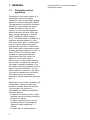
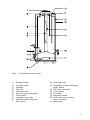
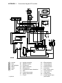
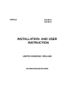
MODELS
BTI 85 G
BTI 100 G
INSTALLATION AND USER
INSTRUCTION
UNITED KINGDOM / IRELAND
HOT WATER STORAGE HEATERS
Read these installation instructions first before installing the appliance. Carefully read
the user instructions before igniting the appliance. Failure to follow these instructions
may lead to risk of explosion and/or fire and could cause material damage and/or bodily
harm. Installation and commisioning should be carried out by a qualified competent
installer. The type of gas and the value at which the appliance is set standard in the
factory are registered on the rating plate. The appliance may only be installed in a room if
this room meets the ventilation requirements.
A.O. SMITH ACCEPTS NO RESPONSIBILITY FOR WARRANTY, SERVICE AND/OR
PRODUCT LIABILITY IN CASE OF UNAUTHORISED ALTERATIONS, PRODUCT
MODIFICATIONS OR REPAIR.
2
CONTENTS
PAGE
1.
1.1
1.2
1.2.1
1.2.2
1.2.3
1.2.4
1.3
1.3.1
1.3.2
GENERAL
Description ...................................................................................................... 4
Technical safety equipment ............................................................................ 6
Gas control valve ............................................................................................ 6
Control panel ................................................................................................... 6
Operation of the storage water heater ........................................................... 7
Combustion products discharge safety device ............................................. 7
Technical information ...................................................................................... 8
Dimensions ..................................................................................................... 8
Technical data ............................................................................................... 10
2.
2.1
2.1.1
2.1.2
2.1.3
2.1.4
2.1.5
2.1.6
2.2
2.2.1
2.2.2
2.2.3
2.3
2.4
2.5
2.6
2.7
2.8
2.8.1
2.8.2
2.8.3
2.8.4
2.9
2.10
2.11
FOR THE INSTALLER
Installation instructions .................................................................................. 12
Installation ..................................................................................................... 12
Water circulation system .............................................................................. 13
Gas connection ............................................................................................. 15
Flue system .................................................................................................. 15
Flue down draught safety device ................................................................. 15
Electrical connection ..................................................................................... 15
Commissioning .............................................................................................. 16
Filling the water heater ................................................................................. 16
Putting in to operation .................................................................................... 16
Shut down .................................................................................................... 16
Removing and replacing the control panel front cover .................................. 17
Setting the gas pressure .............................................................................. 17
Removing and replacing the inner door ......................................................... 18
Temperature regulation ................................................................................. 18
Converting to another type of gas ................................................................ 19
Maintenance ................................................................................................. 19
Magenesium anode ....................................................................................... 19
Cleaning ........................................................................................................ 20
Decalcification ............................................................................................... 20
Spare parts ................................................................................................... 20
Inlet combination ............................................................................................ 20
Gas smell ...................................................................................................... 20
Condensation ................................................................................................ 20
3.
3.1
3.1.1
3.1.2
3.1.3
3.2
FOR THE USER
Commisioning ................................................................................................ 21
Filling the water heater ................................................................................. 21
Putting into operation ..................................................................................... 21
Use ............................................................................................................... 21
Fault overview .............................................................................................. 22
4.
WARRANTY. .................................................................................................... 23
5.
Appendix 1. .................................................................................................... 25
3
1. GENERAL
1.1
Description of the
appliance
Construction of the water heater is in
accordance with the European
standard for gas heated water storage
heaters for sanitary application (EN89).
The appliance thus meets the European
Directory for Gas Appliances and is
therefore entitled to carry the CEmarking. It is an open flued appliance
without ventilator and with a flue gas
down draught safeguard, a Thermal
Reflux Safeguard (TRS) (category
B11BS). The water heater is suitable for a
maximum working pressure of 8 bar.
The water heater tank is manufactured
from low carbon sheet steel and is
glasslined on the inside. In addition the
tank is fitted with a magenesium anode
as extra protection against corrosion. A
thick, CFC-free, PU insulation layer
covered in a steel jacket reduces
unnecessary heat loss. When the
appliance is filled with water it
continuously is under water pressure.
As hot water is drained from the tank,
cold water is added immediately. Four
flue baffles have been placed in the flue
tube to improve heat tranfer. The flue
gasses pass their heat on to the water
by means of radiation and convection.
The exhaust of the flue gasses is
realized by natural thermal draught (see
figur 1).
Dead legs on a hot water installation are
undesireable. Where possible they
should be avoided. When the inclusion
on the system of a dead leg is
unavoidable the following restrictions
should be applied:
- for pipes not eceeding 19 mm. inside
diameter; maximum length of dead leg
permitted 12 metres;
- for pipes exceeding19 mm. but not
exceeding 25 mm. inside diameter;
maximum lenght of dead leg 7,5
metres;
- for pipes with an inside diameter
4
exceeding 25 mm. maximum length of
dead leg 3 metres.
Figur 1 - Cross section of the heater
1)
2)
3)
4)
5)
6)
7)
8)
9)
Draught diverter
Hot water outlet
Insulation
Flue tube
Glass lined tank
Gas valve and spark ignition
Control panel
Inspection cover plate
Intermittent pilot burner and
flame probe
10) Cold water inlet
11) Combustion products discharge
safety device
12) T&P valve connection
13) Outer casting
14) Flue baffle
15) Magnesium anode
16) Drain valve and secondary
return connection
17) Main burner
5
1.2
Technical safety
equipment
The automatic incandescent ignition (hot
surface) ensures that the burner ignites
as soon as there is a demand for heat.
1.2.1 Gas control valve
The water heater is equipped with a
gas control wich regulates the flow of
gas to the burner. The gas block is
equipped with a safety valve, gas valve
and burner control (on a standard
natural gas setting). To ensure
improved ignition the gas control valve
opening mechanism is fitted with a
delay (softlite).
The gas control block is suitable for
gasses from the first, second and third
gas family. The maximum inlet pressure
is 60 mbar.
Figur 2 - Top view of the heater
A)
B)
1)
2)
3)
4)
5)
6
Hot water outlet
Cold water inlet
Electrical connection
ON/OFF switch
Ignition controller reset button
Control thermostat knob
Safety thermostat reset button
1.2.2 Control panel
Temperature control for the water
heater is housed in the control panel
(See figur 2). For safety purposes,
heaters are always fitted with two
thermostats: a control thermostat is
adjustable between 40 °C and 80 °C
and a safety thermostat 90 °C. The
control panel is fitted with an ON/OFF
switch (I/0). At setting ”I”, the gas
control is activated on the basis of heat
demand from the control thermostat. At
setting ”0” the heater is switched off.
1.2.3 Operation of the storage
water heater.
Normal operation
When there is a demand for heat a
waiting period of about 1 second
elapses before the built-in spark generator and pilot gas valve are switched
on. The ignition sparks ignite the pilot
burner and the resulting flame is
detected by the ionisation electrode.
Almost immediately after the pilot flame
is detected, sparking stops and the
main gas valve is openend. The main
burner is lit by the pilot flame. The unit
is now in operation. When the
temperature of the water in the unit
reaches the temperature that is set
with the thermostat, the thermostat
switches and disconnects the
electrical heat demand signal to the
burner controller. The gas valves are
then closed.
operation by pressing its reset button. If
this failure occurs frequently, this
indicates that the flue suffers from down
draught conditions. It is recommended
that a competent person carry out the
necessary remedial action.
Important
The combustion products
discharge safety device should
never be put out of operation. Reentry of flue gases to the building
could be harmful and cause
poisoning or death.
Ignition failure
If the flame is not established within
the safety period the automatic ignition
controller locks out. The safety period
is about 25 seconds. Lock-out is
indicated by the lamp in the RESETbutton on the control panel. The unit
has to be manually reset by pushing
the reset button. If the flame is lost
during normal run, the automatic
ignition controller repeats the start
sequence.
1.2.4 Combustion products
discharge safety device
The heater has been fitted with a
combustion products discharge safety
device. It is the function of the safety
device to prevent flue gases from the
water heater entering the room where
the water heater has been placed,
instead of passing through the flue to
outside atmosphere. The gas supply is
disconnected as soon as the device is
activated by hot gases flowing over
the sensor. After the cause of the reentry of flue gases has been traced
the device can be put back into
7
1.3
Technical information
1.3.1 Dimensions
These water heaters are only suitable
for a flue tube with minimal the
announced diameter (dimension G).
BTI 85
BTI 100
A
1585
1780
B
1450
1640
D
645
675
F
770
775
G
130
130
K
L
340
355
340
370
M
1505
1685
N
1505
1685
P
210
210
R
285
285
S
V
1280
410
1460
410
Dimensions
1
Cold water inlet
2
Hot water outlet
3
Gas control
4
Drain valve
5
T&P relief valve tapping
6
Clean out
All dimensions are given in mm. (rounded off on 5mm). See figur 3.
8
AOS 1092
Figur 3 - Dimensions
9
1.3.2 Technical data
device category: II2H3+
DESCRIPTION
unit
BTI 85
BTI 100
DATA NATUREL GAS G20 - 20 mbar
Nominal capacity
kW
19.2
20.4
Nominal load (gross)
kW
25.1
26.7
Supply pressure
mbar
20
20
Burner pressure
mbar
12.0
7.9
Gas consumption *
m3/h
2.40
2.50
Diameter main orifice
mm
3.90
4.50
Diameter pilot orifice
mm
0.56 / 0.41
0.56 / 0.41
Heating time ∆T= 45K
min
46
58
Nominal load (gross)
kW
24.5
26.0
Nominal capacity
kW
19.2
20.4
Supply pressure
mbar
30
30
Gas consumption *
kg/h
1.8
1.9
DATA BUTANE G30 - 30 mbar
Diameter main orifice
mm
2.30
2.35
Diameter pilot orifice
mm
0.23
0.23
DATA PROPANE G31 - 37 mbar
Nominal heat input (upper valvue)
kW
22.9
24.9
Output
kW
17.9
19.5
Inlet pressure
mbar
37
37
Gas consumption *
kg/h
1.6
1.8
Diameter main orifice
mm
2.30
2.35
Diameter pilot orifice
mm
0.23
0.23
GENERAL
Storage capacity
litres
278
372
Water connections**
-
1-11.5 NPT
11/4-11.5 NPT
Gas connection
-
Rp1/2
Rp1/2
Drain valve
-
3
Anode
-
3
3
T&P plug
-
3
3
/4"-14NPT
/4"-14NPT
/4"-14NPT
3
/4"-14NPT
/4"-14NPT
/4"-14NPT
Maximum operating pressure
bar
8
8
Empty weight
kg
122
149
*
**
10
Gas consumption at 1013,25 mbar and 15 °C
For a leak proof sealed connection European coupling pieces can be used on the NPT
connection nipples with a pipe thread of ISO 228/1
Electrical connection
Electrical
supply
220/240 V AC
Frequency
Electrically
fused to
50 Hz
5A
Ionisation current.
The minimal ionisation current is 0.9 micro-Amperes DC. Below this current the
burner controller will assume no flame
present. When in normal operation, the
ionisation current wil be about 1.2 to 1.3
micro-Amperes DC when only the pilot
flame is burning. (Adjust the main
burner pressure to zero to be able to
measure under this condition) With pilotand main burner in operation, the
ionisation current will be about 6.0 and
6.3 micro-Amperes DC.
Ionisation current can be measured by
connecting a universal-meter in series
in the connection to the ionisation
electrode. Make sure to measure in Direct Current; Alternating Current in fact
gives no information about the system’s
behaviour.
11
2. FOR THE INSTALLER
2.1
Installation instructions
This water heater must be fitted in a
location which will permit the provision
os an approved flue system and adequate ventilation.
A service clearance of 15 cm at the
sides and rear of the unit and 60 cm at
the front of the unit should be allowed
for ease of servicing. Adequate
distance must be allowed between the
top of the unit and any obstruction or
ceiling to allow the flue baffle and
anode to be inspected, cleaned or in the
case of the anode replaced if
necessary.
The water heater must stand on a level
surface resistant to heat, insulted in
accordance with local bylaws and Building Regulations 1985, with sufficient
strength to support the weight of the
unit when full of water.
This water heater must not be installed
in a bathroom, bedroom or in a cupboard opening on to such rooms. This
water heater must not be installed in
any area where flamable materials are
used or stored.
Insufficient ventilation may give rise to a
risk of fire, explosion or suffocation. If
in doubt consult the national and local
regulations governing the installation of
gas appliances or your British gas
sevice department.
2.1.1 Installation
The installation of this water heater
should be carried out by a suitably
qualified competent person. It is a
criminal offence for unqualified persons
to install gas equipment.
Installation should be carried out in
accordance with all local authority and
Building Regualions, Model Water
Bylaws, bylaws of the local water
supplier, Building Standards (Scotland)
(Consolidation) Regulations and any relevant requirements of the Local
Authority, local gas regions and the
following British Standards (current
editions):
12
For domestic applications:
BS 5440 - part 1 and part 2.
BS 5546 - Installation of gas hot water
supplies for domestic
purposes.
BS 6700 - Specifications for design,
installation and maintenance
of services supplying water
for domestic use within
buildings and their
curtilages.
BS 6798 - Specification for installation
of gas fired hot water
boilers of rated input not
exceeding 60 kW.
BS 6891 - Specification for installation
of low pressure gas
pipework of up to 28 mm in
domestic premises.
For non-domestic applications:
BS 5400 - part 1 and part 2.
BS 6798 - Specification for installation
of low pressure gas
pipework of up to 28 mm in
domestic premises.
CP 342 - Code of practice for
centralised hot water
supply part 2, buildings
other than individual
dwellings and the following
additional Codes of Practice.
IM/2
- Purging procedures for nondomestic gas installations.
IM/5
- Soundness testing
procedures for industrial
and commercial gas
installations.
IM/11
- Flues for commercial and
industrial gas fired boilers
and air heaters.
IM/16
- Notes on installation of
pipework (excluding 25 mm
and below).
Some chemicals produce vapours
which can cause rapid failure of mainand pilotburners and storage tanks if
they are drawn into the combustion air
supply.
Therefore if this water heater will be
used to supply hot water to:
- hairdressers,
- dry cleaners,
- industrial degreasing processes
or any other area where
compounds containing halogens are
used and stored, care should be ta
ken that all primary and secondary
air is drawn from outside
atmosphere free of such
contaminents.
For futher advise contact
A.O. Smith.
2.1.2 Water circulation system
A.O. SMITH water heaters are suitable
for connection to vented, unvented and
pumped pressurised systems. In each
case appropriate valves and fittings
should be used to ensure the system
complies with the requirements of the
water by laws, and appropriate building
regulations.
When fitting it is essential the rules of
‘good practice’ are applied at all stages
of installation.
Vented systems (See figur 4)
If the water heater is to be connected to
a cold feed tank or cistern the hot water
supply pipe must include an open vent
which discharges over the cold feed
cistern. The cold feed cistern must have
an actual capacity of greater volume
than the hourly recovery rate of the
water heater(s) which it supplies. The
minimum actual capacity is 50 gallons or
227 litres.
1)
2)
3)
4)
5)
6)
7)
A)
B)
C)
D)
E)
Manual gas valve
Stop valve
Three way valve
Safety valve
Non return valve
Circulation pump
Drain valve
Gas supply
Hot water outlet
Cold water inlet
Overflow
Return circulation loop
AOS 1105
Figur 4 - Connection diagram vented
systems
13
Unvented system (See figur 5)
To install an A.O. Smith water heater on
an unvented cold water supply system
a kit of valves and fittings fisted by the
water reseach centre and complying
with part G3 of the current building
regulations should be used. Installation
should be carried out generally as
shown on the following diagram.
AOS 1119
Figur 5 - Connection diagram unvented
systems
1)
2)
3)
4)
5)
6)
7)
8)
9)
14
Manual gas valve
Stop valve
Expansion vessel
T&P safety valve
Non return valve
Circulation pump
Drain valve
Pressure reducing valve
Expansion valve
A)
B)
C)
D)
E)
Gas supply
Hot water outlet
Cold water inlet
Hot water taps
Return circulation
2.1.3 Gas connection
The gas supply to this appliance must
be installed in accordance with BS 6891
(1988) and British Gas Publications UP1
and UP2.
Fit the 1/2” gas supply cock supplied
with this unit immediately before the gas
control. No heat or soldered joints
should be applied in the vicinity of the
gas control, as they could cause
damage to the control. All connections
and joints should be tested for gas
soundness with a suitable leak detector
(do not use a naked flame).
N.B. When operating this unit on LPG a
suitable gas supply cock should be
used.
2.1.4 Flue system
The water heater should be fitted with a
flue system connected to the draught
diverter. The flue pipe should rise for at
least 50 cm. vertically before the
inclusion of any bends. If a horizontal
run of flue is required this should be
kept to the minimum lenght possible and
incorporate a rise of 6 cm. per metre of
run. A split clip or flange should be
provided in the flue close to the draught
diverter for ease of servicing.
All flue materials should be corrosion
resident i.e. stainless steel or
galvanised and must include a tested
and apprved terminal to BS 5440 part 1.
If the flue passes through any
combustible marerial measures must be
taken to protect against the possibility of
fire.
All flues must terminate in free air space
approx. 1,5 metres from any vertical
surface of structure i.e. chimney
stacks, roof parapets, etc. If an existing
chimney or flue is to be used this should
be swept clean and be free of debris
before an approved liner is installed and
connected to the water heater.
Safeguard (TRS).
This TRS can be recognized by the
copper coloured spiral that is fitted to
the lower edge of the draught diverter.
The spiral is connected to a thermostat
by means of a capillary tube. The wiring
of the thermostat must be connected to
the thermocouple circuit.
Important
The TRS should never be put out of
operation. The reentry of flue
gasses may cause poisoning.
2.1.6 Electrical connection
All electrical connections must be
carried out in accordance with IEE
regulations by an accredited electrical
installation company. The appliance
must be connected to the mains by
means of a permanent electrical
connection. A main switch must be
fitted in the phase between the permanent connection and the water heater.
The feeder cable must have cores of at
least 3 * 1.0 mm2 The connecting clamps
for the electricity supply are indicated
by the symbol for earth Á, N for neutral
and L for live. Always check with a voltage tester if the live and the neutral
have been connected correctly in the
electricity supply. The electricity supply
must comply with the requirements
below:
Electrical
supply
220/240 V AC
Frequency
Electrically
fused to a
minimum of
50 Hz
5A
The maximum power consumption is
25 W
See electrical diagram for more
information, appendix 1.
2.1.5 Draught diverter
The appliance has been fitted with a
flue down draught safety device. The
operation of the safeguard is based on
the principle of the Thermal Reflux
15
2.2
Commissioning
2.2.1 Filling the water heater
1. Close the drain tap.
2. Open the cold water tap to the water
heater and open all taps where hot
water can be drained for de
aeration. The water heater is filled
as soon as cold water flows from all
taps.
3. Close all hot water taps.
2.2.2 Putting into operation
1. Check to see if the heater is filled
with water by running a little to
waste from a hot water tap
connected to the heater.
2. Check wether the ON/OFF switch is
in OFF-position.
3. Ensure gas supply is fully purged of
air and turn on gas cock.
4. Ensure that power has been
correctly supplied to the unit. Use a
voltage tester to check that the live is
to “L” and neutral to “N”. (Flame
detection is phase sensitive).
5. When first starting, the controller can
be in the lock out condition: depress
the reset button to free the control.
(After manual reset, an extended
prepurge/waiting time will occur).
6. Switch the ON/OFF switch into ON
position. If the pilot fails to ignite
within 25 seconds the controls will
go to lock out and the reset button
will need to be reset (wait 15
seconds before attempting reset). It
may be necessary to repeat the
lighting sequence a number of times
on the initial light up if all the air has
not been purged from the gas
supply.
7. The main burner pressure has been
factory set but should be checked
once normal operation is established
(see ‘Ratings’ for settings).
8. Set the temperature regulator to the
required setting (see
‘Descalcification’).
16
Note: If during normal use the reset
button is pressed the gas valves will
close and the automatic ignition
controller will start a new sequence
after releasing the reset button.
2.2.3 Shut down
Note:The water heater should only be
turned off when hot water will not be
required for an extended period (e.g.
holidays); otherwise it should be left on.
To shut down put the ON/OFF switch
into OFF position.
2.3
Removing and
replacing the control
panel front cover
Removing the cover (see figure 7)
1. Remove the screw at the top centre of
the control panel.
2. Push the cover upwards until the
hooks at the lower end clear the
burner access opening and base tray.
3. Pull the lower end of the cover slightly
forward.
4. Pull the cover down until the top edge
is clear of the control panel and then
remove.
Replacing the cover (see figure 7)
1. Place the top of the cover inside the
rim of the control panel and push it up
as far as possible.
2. Position the bottom hooks inside the
burner access opening and over the
rim of the base tray.
3. Push the cover downwards until the
lower hooks engage and the top
screw holes align.
4. Replace the screw in the top centre
of the cover.
2.4
Setting the gas pressure
The gas pressure has been set to the
correct values at the factory.
Important: The following procedure must be followed when
checking or setting the gas
pressure:
1. Shut down the heater by switching
off the mains current (switch off
main switch);
2. Connect a manometer to the
pressure test nipple to measure the
burner pressure on the gas control.
3. Activate the heater and allow the
burner to ignite;
4. Check the burner pressure. If
necessary, reset it by means of the
burner pressure adjusting screw.
Turning it anti-clockwise reduces
burner pressure. Turning it
clockwise increases burner
pressure;
5. Shut down the heater, remove the
manometer and close the pressure
nipple;
6. Restart the heater (test for
soundness).
AOS 1130
Figur 7 taking off and mounting the
control panel
17
2.5
Mounting the inner door
Mode of operation: (see figur 8).
1. Place the clips in the position on the
inner door so the door can fullty stick
into the opening.
2. Lift the door up and rotate it over the
burner into position.
3. Pull the inner door against the inside
of the skirt ring.
4. Rotate the clips into postion with a
tool.
2.6
Temperature regulation
The appliance is under water supply
pressure (maximum 8 bar). The amount
of cold water that is added is equal to
the amount of hot water used. The gas
control block automatically regulates the
gas supply. The main burner will ignite
as soon as a reduction in water
temperature is sended by the
thermostat. The main burner will shut
down as soon as the preset
temperature is achieved.
At high water temperatures there is
more scale buildup in the appliance. It is
for this reason that it is recommended to
place the temperature control knob in
position of
60 °C as the accumulation of scale will
be reduced.
Figur 8 Removing and replacing the
inner door.
1)
2)
3)
4)
18
Burner bracket
Inner door
Clip
Mainburner
5) Skirt ring
6) Outer casting
7) Base tray
2.7
Converting to another
type of gas
2.8
To ensure safe and efficient operation
of the water heater it is recommended
that it is cleaned and serviced at least
once a year by a qualified competent
person.
For conversion of the appliance from
natural gas to another type of gas, or
visa versa, it is necessary to exchange
the pilot injector and the main injector.
The conversion may only be executed
by a qualfied competent person.
2.8.1 Magenesium anode
The life cycle of the anode is
determined by the quality and the
quantity of the water flowing through
the water heater. It is therefore
recommended that the anode be
inspected and replaced if necessary at
least once a year.
1. Close the stop cock in the cold water
supply pipe;
2. Open the nearest hot water tap in
order to allow the pressure to drop
from the water heater and the pipes;
3. Slacken the anode with a fitting
wrench;
4. Check the anode and replace it if it
has been reduced in diameter by
60% or more at any point on its
lenght;
5. Check for water leaks.
Procedure:
1. Shut the heater down. Close the
main inlet gas valve and switch off
the electricity supply at the main
switch;
2. Remove the burner assembly;
3. Replace the injectors with the correct injectors from the conversion
set. (see table below).
Remark:
- When conversion of the appliance
from natural gas to another type of
gas, fix the screw on the gas block
of the burner pressure control as
far as the stop.
-
When conversion of the appliance
from another type of gas to natural
gas, then the right burner pressure
should be adjust.
unit
Maintenance
If is necessary to replace the anode it
should be replaced by one of the same
type. The type of anode required can be
detemined on the basis of the type of
the appliance and the serial number.
BTI 85
BTI 100
G20
G30
G31
G20
G30
G31
Supply pressure
mbar
20
30
37
20
30
37
Burner pressure
mbar
11.5
30
37
10.0
30
37
Diameter main injector mm
3.90
2.30
2.30
4.50
2.35
2.35
Diameter pilot injector
0.56/
0.23
0.23
0.56/
0.23
0.23
mm
0.41
0.41
19
2.8.2 Cleaning
1. Close the gas supply and demount
the burner after it has cooled down
2. Disconnect the burner assembly
from the gas control
3. Remove the complete burrner
assembly
4. Clean the burner with a soft brush
5. Check the pilot burner and clean it if
so required
6. Check the combustion chamber, flue
tube and flue baffle and clean these
if required
After cleaning of the pilot- and main
burner the operation of these should be
checked. If necessary the burner
pressure should be reset.
2.8.3 Decalcification
Formation of lime scale depends on the
quality and quantity of the water used.
In addition higher water temperatures
lead to more deposit in the appliance. A
temperature setting of 60° C is
recommended in order to keep the
calcification at a low level.
Decalcification should be attempted with
the proper means. For extensive
information a decalcification instruction
is available.
2.8.4 Spare parts
To be able to order spare parts it is important to note the type of appliance as
well as the serial number of the
appliance. Based on this information the
data concerning the spare parts can be
determined.
2.9
Inlet combination
Not applicable in U.K. and Ireland.
2.10 Gas smell
Immediately shut the main gas tap. Do
not light any fire or switch o any lights,
do not use any electrical switches or
alarm bells. Open windows. Thoroughly
inspect all gas connections and, if the
20
gas smell persists, alert the local gas
company and/or your installer.
2.11 Condensation
If the appliance is filled with cold water
or if the hot water consumption is very
high, condensation of flue gasses will
occur on the cold surfaces of the
combustion chamber and the flue tube.
The water drops will fall on the burner
and cause a sizzling noise. This is a
normal phenomenon that will disappear
as soon as the appliance reaches its
normal operating temperature.
Important warning
The applicance should never be
taken into operation with a closed
cold water supply!
Provision should always be made
for expansion.
3. FOR THE USER
3.1
Commisioning
8. Set the temperature regulator to the
required setting (see ‘Descalcification’).
Warning
3.1.3 Use
Installing and commissioning of this water heater should only be carried out by
a qualified competent heating engineer.
The appliance is under water supply
pressure (maximum 8 bar). The amount
of cold water that is added is equal to
the amount of hot water used. The gas
control block automatically regulates the
gas supply. The main burner will ignite
as soon as a reduction in water
temperature is sended by the
thermostat. The main burner will shut
down as soon as the preset
temperature is achieved.
At high water temperatures there is
more scale buildup in the appliance. It is
for this reason that it is recommended
to place the temperature control knob in
position of 60 °C as the accumulation of
scale will be reduced.
3.1.1 Filling the water heater
1. Close the drain tap;
2. Open the cold water tap to the water
heater and open all taps where hot
water can be drained for de
aeration. The water heater is filled
as soon as cold water flows from all
taps;
3. Close all hot water taps.
3.1.2 Putting into operation
1. Check to see if the heater is filled
with water by running a little to
waste from a hot water tap
connected to the heater;
2. Check wether the ON/OFF switch is
in OFF-position;
3. Ensure gas supply is fully purged of
air and turn on gas cock;
4. Ensure that power has been
correctly supplied to the unit. Use a
voltage tester to check that the live is
to “L” and neutral to “N”. (Flame
detection is phase sensitive);
5. When first starting, the controller can
be in the lock out condition: depress
the reset button to free the control.
(After manual reset, an extended
prepurge/waiting time will occur);
6. Switch the ON/OFF switch into ON
position. If the pilot fails to ignite
within 25 seconds the controls will
go to lock out and the reset button
will need to be reset (wait 15
seconds before attempting reset). It
may be necessary to repeat the
lighting sequence a number of times
on the initial light up if all the air has
not been purged from the gas
supply;
7. The main burner pressure has been
factory set but should be checked
once normal operation is established
(see ‘Ratings’ for settings);
21
3.2
Fault overview
Failure
Possible Cause
Gas smell
Heater is
off or
does not
ignit
Corrective Action
If you smell gas you should immediately
close the main gas tap, you should not
fight any fire or switch on light. electrical
switches or bels. Open windows and
immediately contact your installer or the
local gas company
Burner automat is in lock
condition
Reset burner automat with the RESET
button on the top of the collumn
Blocked chimney
Contact your installer to investigate the
cause and rectify it
Overheat thermostat is
engaged
Check control thermostat set at 60 °C.
Allow the water to cooldown (open taps).
Puts the RESET button at the panel. The
heater should now operate. If it does not
contact your installer.
Gas supply shut off
Open the inlet gas valve
Temperature set too low
Set water temperature to higher valvue
(60 °C recommended)
Thermal Reflux Safeguard
has shut down the heater
After resetting the TRS activate the heater.
If this occurs regularly, call your installer
Overheat thermostat is
engaged
Allow the water to cool down (opentaps).
Puth the RESET button at the panel.
Supply of hot water exhausted
Reduce hot water use. Give the heater
time to heat the water
Unindentifiable cause
Switch off the elactricity to the heater, close
the inlet gas valve and call your installer
Wrong inlet gas pressure and/or
burner pressure
Set the correct inlet pressure and/or burner
pressure
Dirty injectors
Clean injectors
Poor flame
image
Wrong inlet pressure and/or
burner pressure
Set the correct inlet pressure and/or burner
pressure
Water
leakage
Condensation of (flue) gasses
See chapter “Condensation”
Leakage from other water
heater or pipes in the vicinity
If possible trace the cause and/or call your
installer
Insufficient
hot water,
or none
at all
Explosive
ignition
22
4. WARRANTY
The following conditions form the
guarantee agreement between A.O.
Smith Water Products Company (the
warrantor) and the owner of the water
heater.
4.1
Guarantee in general
If within one year of the original
installation date of the water heater any
part or component other than the tank
shall prove upon examination by the
warrantor or authorised agent to be
defective in material or workmanship,
the warrantor will exchange such part
or component.
4.2
Guarantee of the tank
If within 3 years of the original
installation date, the tank fails due to
rust or corrosion from the water side,
the warrantor will supply a complete
new water heater of equivalent size
and duty (excluding delivery and
installation charges). On the replacement water heater a guarantee will be
granted sufficient to cover the
ubexpired portion of the original 3 years
guarantee of the originally installed water heater.
4.3
Conditions for
installation and use
The guarantee applies to the heater only
while it remains in its original location,
and is installed in accordance with local
plumbing and building regulations and all
relevant Codes of Practice.
d) in a non corrosive atmosphere or
area;
e) with an approved temperature and
pressure relief valve of adequate
capacity not exceeding the working
pressure rating shown on the water
heater, and installed in conformity
with A.O. SMITH Water Products
Companies installation instructions;
f ) when anode(s) have been inspected
and renewed, if they are worn or
erroded by 50% or more at any point
of their length.
4.4
4.5
The water heater should alse have
been used only:
a) for potable water free to circulate at
all times and with the tank free of
damaging scale deposits;
b) at temperatures not exceeding the
maximum setting of its thermostat
and ECO (Energy Cut Off device);
c ) At water pressures and/or energy
inputs which do not exceed those
stated on the rating plate of the water heater;
Exclusions
The guarantee will be null and void:
a) if the water heater has been
damaged by an external cause;
b) in case of misuse, neglect (including
frost damage) or incorrect use of the
water heater;
c ) in case of unauthorised alteration,
modification or repair;
d) in case of ingress into the water
heater of chemicals, pollutants or
contaminants;
e) if the hardness of the incoming water is, or has been, softened below
60 ppm CaCO3;
f ) if the water heater is effected by
corrosive vapours such as those
found in hairdressers, dry cleaners
and laundries or where some
industrial degreasing products are
used and stored (for further
information and advise please contact the A.O. SMITH technical Department).
Range of guarantee
All replacement water heaters supplied
under the terms of this warranty will be
supplied ex stock on a F.O.B basis.
A.O. SMITH accepts no responsability
for carriage, labour or other installation
costs.
23
4.6
Claims
Any claims under this warranty should
be initiated with the dealer who
originally sold the water heater or with
any other dealer or stockist of the
warrantors products.
4.7
No other guarantee or
warrantee either
expressed or implied is
made on behalf of A.O.
SMITH Water Products
Company
With respect to the water heater in
question further A.O. Smith does not
guarantee this water heater as suitable
for purpose except within the terms of
warranty detailed above.
A.O. SMITH Water Products Company
will not be liable by virtue of this
guarantee or otherwise for damage to
any persons or property when arising
out of contracts or tort.
The terms of this guarantee do not effect your statutory rights under United
Kingdom Consumer Legislation.
This guarantee applies to the following
models:
BTI 85 G
BTI 100 G
APPENDIX 1
1
2
3
4
5
6
Connection diagram BTI models
= brown
= blue
= yellow/green
= black
= white
= red
* = Optional
A
B
C
D
E
F
G
H
K
L
=
=
=
=
=
=
=
=
=
=
Ignition controller
ON/OFF switch
Pilot burner
Spark electrode
Flame probe
Transformer flame detection *
TRS
Control thermostat
Safety thermostat
Timer *
M
N
P
R
S
T
U
V
W
X
=
=
=
=
=
=
=
=
=
=
Remote button
Terminal block
Terminal block
Earth terminals
Connector
Gas control valve
Terminal block
Tank earth
Casting earth
Control panel base
plate earth
26
27
0308 253 R0