1
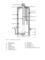
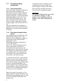
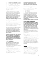
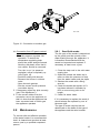
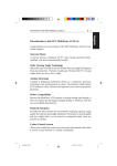
MODELS
EQ 115 G
EQ 155 G
EQH 200 G
INSTALLATION- AND USER
INSTRUCTIONS
HOT WATER STORAGE HEATERS
UNITED KINGDOM / IRELAND
Read these installation instructions first before installing the appliance. Carefully read
the user instructions before igniting the appliance. Failure to follow these instructions
may lead to risk of explosion and/or fire and could cause material damage and/or bodily
harm.
Installation and commissioning should be carried out by a qualified competent installer.
The type of gas and the value at which the appliance is set standard in the factory are
registered on the rating plate. The appliance may only be installed in a room if this room
meets the ventilation requirements.
A.O. SMITH ACCEPTS NO RESPONSIBILITY FOR WARRANTY, SERVICE AND/OR
PRODUCT LIABILITY IN CASE OF UNAUTHORIZED ALTERATIONS, PRODUCT
MODIFICATIONS OR REPAIR.
2
CONTENTS
1.
1.1
1.2
1.2.1
1.2.2
1.3
1.3.1
1.4
2.
2.1
2.1.1
2.1.2
2.1.3
2.1.4
2.1.5
2.2
2.2.1
2.2.2
2.2.3
2.3
2.4
2.5
2.6
2.7
2.8
2.8.1
2.8.2
2.8.3
2.8.4
2.9
2.10
2.10.1
2.10.2
2.10.3
2.10.4
2.10.5
2.11
2.12
3.
3.1
3.1.1
3.1.2
3.1.3
3.1.4
3.1.5
3.2
4.
PAGE
General. ........................................................................................................... 4
Description of the appliance ............................................................................ 4
Technical safety equipment ............................................................................ 6
Gas control valve ............................................................................................ 6
Flue down draught safety device ................................................................... 6
Technical description ...................................................................................... 8
Dimensions ...................................................................................................... 8
Technical data ............................................................................................... 10
For the installer. ............................................................................................ 11
Installation instructions .................................................................................... 11
Installation ........................................................................................................ 11
Water connections .......................................................................................... 11
Gas connection ............................................................................................... 13
Flue system ..................................................................................................... 13
Flue down draught safety device .................................................................... 13
Commissioning ................................................................................................. 14
Filling the water heater .................................................................................... 14
Putting into operation ....................................................................................... 14
Removing and replacing the inner door ........................................................... 15
Pilot adjustment ................................................................................................ 15
Putting out of operation .................................................................................... 15
Temperature regulation .................................................................................... 16
Setting the nominal heat input .......................................................................... 17
Conversion to another type of gas .................................................................. 17
Maintenance .................................................................................................... 19
Sacrificial anode .............................................................................................. 19
Cleaning ........................................................................................................... 20
Inspection of the internal waterside surfaces ................................................. 20
Spare parts ..................................................................................................... 20
Inlet combination .............................................................................................. 20
Fault finding ..................................................................................................... 21
Safety thermostat ............................................................................................ 21
Flue down draught safety device .................................................................... 21
Hot water temperature too low ....................................................................... 21
Hot water temperature too high ....................................................................... 21
Possible water leakage ................................................................................... 21
Gas smell ......................................................................................................... 21
Condensation .................................................................................................. 21
For the user. .................................................................................................. 22
Commissioning ................................................................................................. 22
Filling the water heater .................................................................................... 22
Putting into operation ....................................................................................... 22
Use .................................................................................................................. 22
Putting out of operation .................................................................................... 22
Maintenance .................................................................................................... 23
Fault finding ..................................................................................................... 24
Guarantee. ..................................................................................................... 26
3
1.
GENERAL
1.1
Description of the
appliance
Construction of the water heater is in
accordance with the European
standard for gas heated water storage
heaters for sanitary application (EN 89).
The appliance thus meets the European
Directory for Gas Appliances and is
therefore entitled to carry the CEmarking. It is an open flued appliance
without ventilator and with a flue gas
down draught safeguard (category
B11BS). The water heater is suitable
for a maximum working pressure of 8
bar. The water-heater tank is
manufactured from low carbon sheet
steel and is glass-lined on the inside. In
addition the tank is fitted with a
sacrificial anode as an extra protection
against corrosion.
A thick PU-insulation layer covered in a
steel jacket reduces unnecessary heat
loss. When the appliance is filled with
water it continuously is under water
pressure.
As hot water is drained from the tank,
cold water is added immediately. A flue
baffle has been placed in the flue tube
to improve heat transfer. The flue
gasses pass their heat on to the water
by means of radiation and convection.
The flue gasses are guided to the
chimney via the draught diverter. The
exhaust of the flue gasses is realized
by natural thermal draught (see Figure
1).
Dead legs on a hot water installation are
undesireable. Where possible they
should be avoided. Where the inclusion
on the system of a dead leg is
unavoidable the following restrictions
should be applied:
- for pipes not exceeding 19 mm.
inside diameter; maximum lengh of
dead leg permitted 12.0 metres;
- for pipes exceeding 19 mm. but not
4
-
exceeding 25 mm. inside diameter;
maximum length of dead leg 7.5
metres;
for pipes with an inside diameter
exceeding 25 mm. maximum dead leg
3.0 metres.
AOS 0478
Figure 1 - Cross-section of the heater
1)
2)
3)
4)
5)
6)
7)
8)
Draught diverter
Hot water outlet
Insulation
Flue tube
Glass lined tank
Gas control valve
Cold-water inlet
T&P valve connection
9)
10)
11)
12)
13)
14)
Outer casting
Flue baffle
Sacrificial anode
Drain valve
Atmospheric burner
Pilot light burner with thermocouple
5
1.2
Technical safety
equipment
1.2.1 Gas control valve
The water heater has been fitted with a
gas control block consisting of a
thermo-electrical pilot flame safeguard,
pilot flame pressure regulator, burner
pressure regulator, a control thermostat
(adjustable between 30°C and 71°C)
and a safety thermostat (82°C). This
gas control block with its simple and
secure control respectively switches
the gas supply to the main burner on or
off.
This gas control block is suitable for
gasses from the first, second and third
gas family. The maximum inlet pressure
is 50 mbar.
1.2.2 Flue down draught safety
device
The appliance must be fitted with a flue
down draught safety device. The
operation of the safeguard is based on
the principle of the Thermal Reflux
Safeguard (T.R.S.).
The appliance has been fitted with a
T.R.S., see Figure 2.
This T.R.S. can be recognized by the
brass colored helix coil which is
connected to the lower edge of the
draught diverter. The helix coil has been
connected to the thermostat by means
of a capillary tube. The wiring that is
connected to the thermostat must be
connected to the thermocouple.
It is the aim of the T.R.S. to prevent flue
gasses from the water heater entering
the room where the water heater has
been placed, instead of passing through
the flue to outside atmosphere. The
thermo-couple circuit is interrupted and
the gas supply is disconnected as soon
as the T.R.S. is activated by heating of
the sensor by the hot gasses.
After the cause of the reentry of flue
gasses has been traced the device can
be put back into operation again. In case
of T.R.S. the RESET button has to be
pressed first.
6
If this failure occurs frequently, this
indicates that the flue suffers from
down draught conditions. We advice
that necessary remedial actions be
carried out by a competent person.
Important
The T.R.S. should never be put out
of operation. Reentry of flue
gasses to the building could be
harmful and cause poisoning or
death.
AOS 0479
Figure 2 - Gas control block with T.R.S.
1)
2)
3)
T.R.S. thermostat
Sensor combustion products
dicharge safety device
Thermocouple with built-in
interrupter
4)
5)
6)
7)
8)
Thermocouple
Gas control block
Reset button
Pilot burner
Temperature regulator knob
7
1.3
Technical description
1.3.1 Dimensions
These water heaters are only suitable
for a flue tube with minimal the
announced diameter (dimension G).
Dimensions
EQ 115
EQ 155
EQH 200
A
1280
1370
1670
B
D
1120
465
1210
515
1540
515
F
545
595
605
G
80
80
100
K
325
325
380
L
270
295
395
M
N
1180
1180
1270
1270
1590
1590
R
230
230
255
S
945
1030
1380
V
205
205
205
1
Cold water inlet
2
3
Hot water outlet
Gas control valve
4
Drain valve
5
T&P valve tapping
All dimensions are given in mm (rounded
off on 5 mm).
8
AOS 0481
Figure 3 - Dimensions
9
1.4
Technical data
Device category: II2H3+
DESCRIPTION
unit
EQ 115
EQ 155
EQH 200
kW
9.3
11.3
18.3
DATA NATURAL GAS G20 - 20 mbar:
Nominal load (gross)
Nominal capacity
kW
7.4
9.0
14.0
Suppy pressure
mbar
20
20
20
Burner pressure
mbar
12.5
12.5
10.5
Gas consumption *
m3/h
0.9
1.1
1.7
Diameter main orifice
mm
2.35
2.60
3.50
Diameter pilot orifice
mm
2 x 0.27
2 x 0.27
2 x 0.27
Heating time ∆T= 44 K
min.
45
49
40
DATA BUTANE G30 - 28/30 mbar:
Nominal load (gross)
kW
10.1
12.2
17.6
Supply pressure
mbar
30
30
30
Burner pressure
mbar
30
30
30
Gas consumption *
kg/h
0.7
0.9
1.3
Diameter main orifice
mm
1.40
1.50
1.95
Diameter pilot orifice
mm
0.22
0.22
0.22
DATA PROPANE G31 - 37 mbar:
kW
9.8
11.8
17.2
Supply pressure
Nominal load (gross)
mbar
37
37
37
Burner pressure
mbar
37
37
37
Gas consumption *
kg/h
0.7
0.8
1.3
Diameter main orifice
mm
1.40
1.50
1.95
Diameter pilot orifice
mm
0.22
0.22
0.22
GENERAL
Storage capacity
litres
109
144
181
Water connections **
-
3
3
3
Gas connection
-
ISO 7/1 Rp 1/2
ISO 7/1 Rp 1/2
ISO 7/1 Rp 1/2
Drain valve
-
3
3
3
Anode
-
3
3
3
-
3
3
3
T&P-plug
/4" - 14 NPT
/4" - 14 NPT
/4" - 14 NPT
/4" - 14 NPT
/4" - 14 NPT
/4" - 14 NPT
/4" - 14 NPT
/4" - 14 NPT
/4" - 14 NPT
/4" - 14 NPT
/4" - 14 NPT
/4" - 14 NPT
Maximum operating pressure
bar
8
8
8
Empty weight
kg
47
52
75
*
Gas consumption at 1013,25 mbar and 15°C
**
For a leak-proof sealed connection European coupling pieces can be used on the NPT-connection nipples with a pipe thread
of ISO 228/1
10
2.
FOR THE INSTALLER
2.1
Installation instructions
This water heater must be fitted in a
location which will permit the provision
of an approved flue system and
adequate ventilation.
A service clearance of 15 cm at the
sides and rear of the unit and 60 cm at
the front of the unit should be allowed
for ease of servicing. Adequate
distance must be allowed between the
top of the unit and any obstruction or
ceiling to allow the flue baffle and
anode to be inspected, cleaned or in the
case of the anode replaced if
necessary.
The water heater must stand on a level
surface resistant to heat and with
sufficient strength to support the weight
of the unit when full of water.
This water heater must not be installed
in a bath room, bedroom or in a cupboard opening on to such rooms. This
water heater must not be installed in
any area where flamable materials are
used or stored.
Insufficient ventilation may give rise to a
risk of fire, explosion or suffocation. If
in doubt consult the national and local
regulations governing the installation of
gas appliances or your local British gas
service department.
2.1.1 Installation
The installation of this water heater
should be carried out by a suitably
qualified competent person. It is a
criminal offence for unqualified persons
to install gas equipment.
Installation should be carried out in
accordance with all local authority and
building regulations, local water
authority and fire regulations and the
following British standards: 5440, 5546,
6644, 6700, 6798 and 6891.
Some chemicals produce vapours
which can cause rapid failure of
thermocouples, burners and storage
tanks if they are drawn into the
combustion air supply.
Therefore if this water heater will be
used to supply hot water to:
- hairdressers,
- dry cleaners
- industrial degreasing processes
or any other area where compounds
containing halogens are used and
stored, care should be taken that all
primary and secondary air is drawn
from outside atmosphere free of such
contaminents.
For further advise contact A.O. SMITH.
2.1.2 Water connections
A.O. Smith water heaters are suitable
for connection to vented, unvented and
pumped pressurised systems. In each
case appropriate valves and fittings
should be used to ensure the system
complies with the requirements of the
water by laws, and appropriate building
regulations.
When fitting it is essential the rules of
'good practice' are applied at all stages
of installation.
Vented systems
If the water heater is to be connected to
a cold feed tank or cistern the hot water
supply pipe must include an open vent
which discharges over the cold feed
cistern. The cold feed cistern must have
an actual capacity of greater volume
than the hourly recovery rate of the
water heater(s) which it supplies.The
minimum actual capacity is 50 gallons or
227 litres.
Unvented
To install an A.O. Smith water heater on
an unvented cold water supply system
a kit of valves and fittings listed by the
water research centre and complying
with part G3 of the current building
regulations should be used. Installation
should be carried out generally as
shown on the following diagram.
11
See Figure 4.
A.O. Smith water heaters are tested to
a maximum pressure of 12 bar and a
maximum working pressure of 8 bar.
AOS 0581
Figure 4 - Connection diagram
(unvented system)
1)
2)
3)
4)
5)
6)
7)
12
Manual gas valve
Stop valve
Expansion vessel
T&P safety valve
Non return valve
Circulation pump
Drain valve
8)
9)
A)
B)
C)
D)
E)
Pressure limiting valve
Expansion valve
Gas supply
Hot water delivery
Cold water inlet
Hot water taps
Return circulation
2.1.3 Gas connection
The gas supply to this appliance must
be installed in accordance with BS 6891
(1988).
Fit the 1/2" gas supply cock supplied
with this unit immediately before the gas
control block. No heat or soldered joints
should be applied in the vicinity of the
gas control block, as they could cause
damage to the control.
All connections and joints should be
tested for gas soundness with a
suitable leak detector (do not use a
naked flame).
2.1.4 Flue system
The water heater should be fitted with a
flue system connected to the draught
diverter. The flue pipe should rise for at
least 50 cm. vertically before the
inclusion of any bends. If a horizontal
run of flue is required this should be
kept to the minimum length possible and
incorporate a rise of 6 cm. per metre of
run. A split clip or flange should be
provided in the flue close to the draught
diverter for ease of servicing.
All flue materials should be corrosion
resistant i.e. stainless steel or
galvanised and must include a tested
and approved terminal to BS 5440 part I.
If the flue passes through any
combustible material measures must be
taken to protect against the possibility of
fire.
All flues must terminate in free air space
approx. 1.5 metres from any vertical
surface of structure i.e. chimney
stacks, roof parapets, etc. If an existing
chimney or flue is to be used this should
be swept clean and be free of debris
before an approved liner is installed and
connected to the water heater.
supervision must remain installed on
the draught hood.
Connect the slide connectors of the
down draught supervision to the
thermocouple (see Figure 5) and install
the head of the down draught
supervision in the bracket; see Figure
5. The draught hood must be positioned
in its normal place with the temperature
probe at the front of the boiler. Pass
the wiring of the temperature probe
through the cable duct.
Note
The screws with which the down
draught supervision has been mounted
in the bracket are already in the
bracket.
IMD 0422
IMD 0422
Figure 5 - Down draught supervision
installation
2.1.5 Flue down draught safety
device
The draught diverter has already been
provided with a temperature probe ex
factory for signalling returning flue
gases. The probe of the down draught
13
2.2
Commissioning
2.2.1 Filling the water heater
1. Close the drain tap.
2. Open the cold water tap to the water
heater and open all taps where hot
water can be drained for deaeration. The water heater is filled
as soon as cold water flows from all
taps.
3. Close all hot water taps.
2.2.2 Putting into operation
1. Check whether the water-heater
has been filled with water and
whether the gas supply to the water
heater is open.
2. Turn the temperature control knob
clockwise and place the control knob
in the ‘PILOT’-position (✸).
3. Remove the outer and inner door of
the combustion chamber.
4. Keep the control knob pushed-in and
press the piezo-ignitor several times
until the pilot burns (see Figure 6).
5. Keep the control button (✸) pushedin for approximately 20 seconds.
After releasing the button the pilot
should remain burning. If the pilot
extinguishes you should wait 5
minutes before repeating the ignition
procedure. The size of the pilot flame
can be adjusted (see also “Pilot
adjustment”).
6. Subsequently remount the outer and
inner door; see “Mounting the inside
door”.
7. Turn the control button to the ‘ON’
( ) position.
8. Check the burner pressure setting
(see Fig. 9) and adjust if required
based on the technical information
(see section 1.4).
9. Place the temperature control button
in the correct position, preferably
position 4 (approximately 60°C). The
appliance will now operate fully
automatically.
AOS 0484
Figure 6 - Operation of the gas control
block
14
2.2.3 Removing and replacing
the inner door
(only for the EQ 115/155 models, see
Figure 7a).
Procedure:
1. Place lip A through the recess on the
right and subsequently slide it down
behind the steel wall. See to it that
both lower lips remain in front of the
metal wall.
2. Press lip B through the recess on
the left.
3. Subsequently slide lip B behind the
steel wall (see Figure 7a).
A
B
AOS 0520
(only for the EQH 200 model, see Figure
7b).
Procedure:
1. Turn down both clamps (1).
2. Place the entire door into the
appliance and move the opening
over the burner venturi.
3. Turn both clamps outward (3),
pushing them over the edge of the
burner chamber.
2.3
Figure 7a - Mounting the inside door
Pilot adjustment
The pilot can be adjusted by means of
the regulating screw under the plastic
cover on the right hand side of the gas
control block.
Turn the screw clockwise to reduce the
gas pressure and anti clockwise to
increase the pressure. Care should be
taken to ensure the pilot covers the
thermocouple element correctly
3
3
1
1
IMD 0359
Figure 7b - Mounting the inside door
2.4
Putting out of operation
1. For short periods of time the control
knob should be turned to (✸); the
pilot keeps burning.
2. For longer periods of time the knob
should be turned to the (●) position;
the pilot is extinguished.
3. Close the gas tap in the supply pipe.
In case of longer interruptions or in
the event of risk of frost it is
15
recommended to also close the cold
water tap and to drain the appliance
after cooling (open the drain tap; it is
possible to connect a drain hose to
the drain tap; open the nearest hot
water drain point to prevent air
locks).
To be able to drain the appliance
completely it should be disconnected
and tilted slightly in the direction of
the drain tap.
2.5
Temperature regulation
The appliance is under water supply
pressure (maximum 8 bar). The amount
of cold water that is added is equal to
the amount of hot water used. The gas
control block automatically regulates the
gas supply. The main burner will ignite
as soon as a reduction in water
temperature is sensed by the
thermostat. The main burner will shut
down as soon as the preset
temperature is achieved.
Position 1 = approximately 30°C
Position 2 = approximately 40°C
Position 3 = approximately 50°C
Position 4 = approximately 60°C
Position 5 = approximately 70°C
At high water temperatures there is
more scale buildup in the appliance. It is
for this reason that it is recommended to
place the temperature control knob in
position 4 as the accumulation of scale
will be reduced. In addition a safety
thermostat has been fitted. This
thermostat completely shuts off the gas
supply if the water temperature
reaches 82°C, also extinguishing the
pilot burner.
AOS 0485
Figure 8 - Setting the pilot
16
2.6
Setting the nominal
heat input
The gas control has been factory
preset to the water heater nominal heat
input.
A further check of the burner pressure
should be carried out during the
commissioning of the unit after
installation. The following procedure
should be followed.
1. Remove the protruding cover screw
on the right side of the gas control
block and connect a U-gauge
manometer to the outlet.
2. Put the appliance into operation and
ignite the burner.
3. Check the burner pressure and, if
necessary, reset by means of the
adjusting screw “pr adj” (pressure
adjustment; see Figure 9). To make
this possible the temperature control
knob should be removed by pulling it
straight forward, making the “pr adj”
visible. Turning clockwise reduces
the pressure; turning anti clockwise
increases the pressure. It is
recommended to check the heat
input by means of the gas meter.
4. Turn off the appliance and remove
the manometer hose and replace the
adjusting screw.
5. Replace the thermostat control knob.
6. Put the appliance into operation.
2.7
Converting to another
type of gas
For conversion of the appliance from
natural gas to another type of gas, or
vice versa, it is necessary to exchange
the pilot injector and the main injector.
The conversion may only be executed
by a qualified competent person.
AOS 0486
Figure 9 - Setting the nominal load
17
Description
Unit
EQ 115
EQ 155
G20
G30
G31
G20
G30
G31
Inlet pressure
mbar
20
30
37
20
30
37
Burner pressure
mbar
12.5
30
37
12.5
30
37
Diameter main injector
mm
2.35
1.40
1.40
2.60
1.50
1.50
Diameter pilot injector
mm
2x0.27
0.22
0.22
2x0.27
0.22
0.22
Description
Unit
EQH 200
G20
G30
G31
Inlet pressure
mbar
20
30
37
Burner pressure
mbar
10.5
30
37
Diameter main injector
mm
3.50
1.95
1.95
Diameter pilot injector
mm
2x0.27
0.22
0.22
Procedure:
1. Close the main gas tap in the gas
supply.
2. Demount the burner (see “Cleaning”).
3. Replace the injector of the main
burner and the pilot burner with the
correct injectors from the conversion
set (see tables above).
18
4.a Conversion from natural gas to
LP- gas
- Put the pressure regulation of the
gas control block out of operation.
To do this the temperature
regulating knob should be pulled
straight forward. Turn the ‘no pr’
(no pressure regulation) screw
down tight (see Figure 10).
- Seal this setting with lacquer.
- Remount the burner in reverse
order.
- Open the main gas tap.
AOS 0487
Figure 10 - Conversion to another gas
4.b Conversion from LP-gas to natural
gas:
- Put the pressure regulator into
operation. To do this the
temperature regulating knob
should be pulled straight forward.
Next the red plastic cover that is
now visible, should be removed.
Turn the ‘no pr’ (no pressure
regulation) screw completely up
(see Figure 10).
- Seal this setting with lacquer.
- Remount the burner in reverse
order.
- Open the main gas tap.
- Set the correct burner pressure
(see table above).
5. If necessary adjust the pilot correctly
(see “Pilot adjustment”).
6. Fit the correct sticker from the
conversion set on the appliance so
that it is clear that the appliance has
been converted and on which gas
the appliance operates.
2.8
Maintenance
2.8.1
Sacrificial anode
The life cycle of the anode is determined
by the quality and the quantity of the
water flowing through the apparatus. It
is therefore recommended that the
anode be inspected and replaced if
necessary at least once a year.
1. Close the stop cock in the cold water
supply pipe,
2. Open the nearest hot water tap in
order to allow the pressure to drop
from the water heater and the pipes,
3. Slacken the anode with a fitting
wrench,
4. Check the anode and replace it if it
has been reduced in diameter by
60% or more at any point on its
length,
5. Check for water leaks.
If it is necessary to replace the anode it
should always be replaced by one of
the same type.
The type of anode required can be
determined on the basis of the type of
the appliance and the serial number.
To ensure safe and efficient operation
of the water heater it is recommended
that it is cleaned and serviced at least
once a year by a qualified competent
person.
19
2.8.2 Cleaning
1. Close the gas supply and demount
the burner after it has cooled down,
2. Disconnect the burner, pilot pipe and
thermo couple from the gas control
block (see Figure 11),
3. Remove the complete burner
assembly,
4. Clean the burner with a soft brush.
5. Check the pilot burner and clean it if
so required,
6. Check the combustion chamber, flue
tube and flue baffle and clean these
if required,
7. Re-mount in reverse order. Tighten
the thermo couple connection on the
gas control block hand tight and
tighten it further with a wrench to a
maximum of 1/4 turn as it only needs
to make contact.
After cleaning of the pilot- and main
burner the operation of these should be
checked. If necessary the burner
pressure of the main burner should be
reset.
2.8.3 Inspection of the internal
waterside surfaces
Formation of lime scale depends on the
quality and quantity of the water used.
In addition higher water temperatures
lead to more deposit in the appliance. A
temperature setting of 60°C is
recommended in order to keep the
calcification at a low level.
Decalcification should be attempted with
the proper means. For extensive
information a decalcification instruction
is available.
2.8.4 Spare parts
To be able to order spare parts it is
important to note the type of appliance
as well as the serial number of the
appliance. Based on this information the
data concerning the spare parts can be
determined.
2.9
Inlet combination
Not applicable in U.K. and Ireland.
AOS 0488
Figure 11- Mounting burner-set
20
2.10 Fault finding
2.10.4 Hot water temperature too
high
In case of failure the following should
be checked.
Check whether the control thermostat is
set too high.
2.10.1 Safety thermostat
2.10.5 Possible water leakage
All appliances have been fitted with a
safety thermostat that shuts off the gas
supply when the water temperature is
too high. The safety thermostat remains
activated until the water temperature
drops below the safety temperature.
The water heater must be reignited
manually. The regulation thermostat
should be set to a lower water
temperature. If the pilot is extinguished
repeatedly at higher temperatures than
normal, this indicates that the safety
thermostat is operating.
1. Check whether the drain tap is fully
closed.
2. Check whether all water
connections are water tight.
3. Check whether the possible water
leakage could be caused by
condensation.
2.10.2 Flue down draught safety
device
If the flue tube safety device has
switched off the appliance, the
appliance can be put back into operation
through the normal procedure. If the flue
tube safety device repeatedly puts the
appliance out of operation then this
points to problems with the flue. The
only remedy is to determine the cause
of the problem (for instance a blocked
chimney) and to solve the problem.
2.10.3 Hot water temperature too
low
1. Check the setting of the temperature
control knob.
2. Check whether the pilot is alight. If
necessary ignite (see “Putting into
operation”).
3. Check whether there are any leaks
or open taps.
4. Is the gas supply adequate? Check
and correct if necessary.
5. Perhaps the hot water consumption
is higher than was originally
calculated.
6. Check whether the cold water inlet
has been correctly connected.
7. Check the thermostat sensor for
scale build up.
2.11 Gas smell
Warning
Immediately shut the main gas tap. Do
not light any fire or switch on any lights,
do not use any electrical switches or
alarm bells. Open windows. Thoroughly
inspect all gas connections and, if the
gas smell persists, alert the local gas
company and/or your installer.
2.12 Condensation
If the appliance is filled with cold water
or if the hot water consumption is very
high, condensation of flue gasses will
occur on the cold surfaces of the
combustion chamber and the flue tube.
The water drops will fall on the burner
and cause a sizzling noise. This is a
normal phenomenon that will disappear
as soon as the appliance reaches its
normal operating temperature.
Important warning
The applicance should NEVER be
taken into operation with a closed
cold water supply!
Provision should always be made
for expansion.
21
3.
FOR THE USER
3.1
Commissioning
Warning
Installing and commissioning (for the
first time) of this water heater should
only be carried out by a qualified
competent heating engineer.
3.1.1 Filling the water heater
1. Close the drain tap.
2. Open the cold water tap to the water
heater and open all taps where hot
water can be drained for deaeration. The water heater is filled
as soon as cold water flows from all
taps.
3. Close all hot water drain taps.
3.1.2 Putting into operation
1. Check whether the device has been
filled with water and whether the
gas supply to the water heater is
open.
2. Turn the temperature control knob
clockwise and place the control knob
in the ‘PILOT’-position (✸).
3. Remove the outer and inner door of
the combustion chamber.
4. Keep the control button pushed-in
and press the piezo-ignitor several
times until the pilot burns (see Figure
6).
5. Keep the control button (✸) pushedin for approximately 20 seconds.
After releasing the button the pilot
should remain burning. If the pilot
extinguishes you should wait 5
minutes before repeating the ignition
procedure.
6. Subsequently remount the inner and
outer door; see “Mounting the inside
door”.
7. Turn the control button to the ‘ON’
( ) position.
8. Place the temperature control button
in the correct position, preferably
position 4 (approximately 60°C). The
appliance will now operate fully
automatically.
22
3.1.3 Use
The appliance is under water supply
pressure (with a maximum of 8 bar).
The amount of cold water that is added
is equal to the amount of hot water
used. The gas control block
automatically regulates the gas supply.
The main burner will ignite as soon as a
reduction in water temperature is
sensed by the control thermostat. The
main burner will shut down as soon as
the water temperature returns to the
preset temperature.
Position 1 = approximately 30°C
Position 2 = approximately 40°C
Position 3 = approximately 50°C
Position 4 = approximately 60°C
Position 5 = approximately 70°C
Higher water temperatures will cause
more scale build up in the appliance. It is
for this reason that it is recommended to
place the temperature control knob in
position 4 as the accumulation of scale
will be reduced at lower temperatures.
In addition a safety thermostat has been
fitted. This thermostat completely shuts
off the gas supply if the water
temperature reaches 82°C, also
extinguishing the pilot burner.
3.1.4 Putting out of operation
1. For short periods of time the control
knob should be turned to (✸); the
pilot keeps burning.
2. For longer periods of time the knob
should be turned to the (●) position;
the pilot is extinguished.
3. Close the gas tap in the supply pipe.
In case of longer interruptions or in
the event of risk of frost it is
recommended to also close the cold
water tap and to drain the appliance
after cooling (open the drain tap; it is
possible to connect a drain hose to
the drain tap; open the nearest hot
water drain point to prevent
airlocks).
To be able to drain the appliance
completely it should be disconnected
and tilted slightly in the direction of
the drain tap.
3.1.5 Maintenance
The inlet combination has to be tested
regularly by relieving it (via the relief
button). The water has to flow out in a
forceful jet. Check whether the
discharge pipe is open.
We recommend a service agreement on
an annual basis.
To be able to order spare parts it is
important to note the type of appliance
as well as the serial number of the
appliance. Based on this information the
data concerning the spare parts can be
determined.
23
3.2
Fault finding
Fault
Possible cause
Gas smell
Pilot
extinguishes
Corrective action
If you smell gas you should immediately
close the main gas tap you should not
light any fire or switch on light,
electrical switches or bells. Open
windows and immediately contact your
installer or the local gas company.
Blocked pilot burner
Clean the pilot burner
Blocked chimney
Find the cause and remove it.
Safety thermostat
Set the temperature regulator at a lower
temperature.
Thermocouple defective
Replace the thermocouple
Thermocouple makes no
contact
Restore the connection
Gas supply closed
Open the gas tap
Down draught
supervision not
connected.
Connect by sliding the two connectors
of the down draught supervision on to
the thermocouple.
Temperature is set too
Insufficient
hot water, or l o w
none at all
Control knob in position
(✸) (pilot burns )
Control knob in position
Set the temperature regulator at a higher
temperature
Turn the temperature regulator
completely clockwise; turn control button
to “on” ( ); turn the temperature
regulator to the desired position,
preferably position 4. The appliance now
operates fully automatically.
Put the appliance into operation.
(l)
Flue safety device closed
the gas supply
Press the reset button - if present - on
the safety thermostat and put the
appliance into operation. If this occurs
more often then you should inform your
installer.
Gas supply closed
Open the gas tap and put the appliance
into operation.
Fault
Possible cause
Corrective action
Insufficient
hot water, or
none at all
Safety thermostat has
closed the gas supply
because the water
temperature was too high
Set the temperature regulator at a
lower temperature and reignite the
pilot burner.
Hot water storage empty
Reduce the consumption of hot water.
Allow the appliance time to heat the
water.
Cause cannot be
determined
Turn the control button to the (l)
position. Close the gas tap and inform
your installer.
Condensation of (flue)
gasses
See “Condensation”.
Insufficient sealing of the
water connections
(thread)
Tighten the threaded connections.
Leakage from other
water- appliances or
pipes near by
Trace the cause.
Condensation leakage
from the underside of the
appliance (usually during
the first warming-up
period).
Reduce your hot water use. Allow the
appliance enough time to warm up
water.
Water
leakage
4.
GUARANTEE
The following conditions form the
guarantee agreement between A.O.
Smith Water Products Company (the
warrantor) and the owner of the water
heater.
4.1
Guarantee in general
If within one year of the original
installation date of the water heater
any part or component other than the
tank shall prove upon examination by
the warrantor or authorised agent to
be defective in material or workmanship, the warrantor will exchange
such part or component.
4.2
Guarantee of the tank
If within 3 years of the original
installation date, the tank fails due to
rust or corrosion from the water side,
the warrantor will supply a complete
new water heater of equivalent size
and duty (excluding delivery and
installation charges). On the
replacement water heater a guarantee
will be granted sufficient to cover the
unexpired portion of the original 3 year
guarantee of the originally installed
water heater.
4.3
Conditions for installation
and use
The guarantee applies to the heater
only while it remains in its orignial
location, and is installed in accordance
with local plumbing and building
regulations and all relevant Codes of
Practice.
The water heater should also have
been used only:
a) for potable water free to circulate at
all times and with the tank free of
damaging scale deposits;
b) at temperatures not exceeding the
maximum setting of its thermostat
and ECO (Energy Cut Off device);
c ) at water pressures and/or energy
inputs which do not exceed those
stated on the rating plate of the
water heater;
26
d) in a non corrosive atmosphere or
area;
e) with an approved temperature and
pressure relief valve of adequate
capacity not exceeding the working
pressure rating shown on the
water heater, and installed in
conformity with A.O. Smith Water
Products Companies installation
instructions;
f ) when anode(s) have been
inspected and renewed, if they are
worn or erroded by 50% of more at
any point of their length.
4.4
a)
b)
c)
d)
e)
f)
Exclusions
The guarantee will be null and void:
if the water heater has been
damaged by an external cause;
in case of misuse, neglect (including
frost damage) or incorrect use of
the water heater;
in case of unauthorised alteration,
modification or repair;
in case of ingress into the water
heater of chemicals, pollutants or
contaminants;
if the hardness of the incoming
water is, or has been, softened
below 60 ppm CaCO3 ;
if the water heater is effected by
corrosive vapours such as those
found in hairdressers, dry cleaners
and laundries or where some
industrial degreasing products are
used and stored (for further
information and advise please
contact the A.O. Smith Technical
Department).
4.5
Range of guarantee
All replacement water heaters supplied
under the terms of this warranty will
be supplied ex stock on an F.O.B.
basis. A.O. Smith accepts no
responsability for carriage, labour or
other installation costs.
4.6
Claims
Any claim under this warranty should
be initiated with the dealer who
originally sold the water heater or with
any other dealer or stockist of the
warrantors products.
4.7
No other guarantee or
warranty either expressed
or implied is made on
behalf of A.O. Smith Water
Products Company.
With respect to the water heater in
question further A.O. Smith does not
guarantee this water heater as suitable
for purpose except within the terms of
warranty detailed above.
A.O. Smith Water Products Company
will not be liable by virtue of this
guarantee or otherwise for damage to
any persons or property when arising
out of contracts or tort.
The terms of this guarantee do not
effect your statutory rights under
United Kingdom Consumer Legislation.
27
Important
This form should be filled in completely
within two weeks of installation.
MODEL: .........................................................................................................................
SERIAL NUMBER: .........................................................................................................
ORIGINAL DATE OF INSTALLATION: ............................................................................
NAME OWNER: .............................................................................................................
ADDRESS: ....................................................................................................................
TOWN: ..........................................................................................................................
(STAMP) INSTALLER: ...................................................................................................
28
29
30
31
0307 985 R1
32