1
FCC REGULATIONS (For 120V models)
This equipment has been tested and found to comply with the limits for a Class A digital device, pursuant to Part 15 of the FCC Rules. These
limits are designed to provide reasonable protection against harmful interference when the equipment is operated in a commercial environment. This equipment generates, uses, and can radiate radio frequency energy and, if not installed and used in accordance with the instruction
manual, may cause harmful interference to radio communications. Operation of this equipment in a residential area is likely to cause harmful
interference in which case the user will be required to correct the interference at his own expense.
Do not make any changes or modifications to the equipment unless otherwise specified in the manual. If such changes or modifications should
be made, you could be required to stop operation of the equipment.
RADIO INTERFERENCE REGULATIONS (For 120V models)
This digital apparatus does not exceed the Class A limits for radio noise emissions from digital apparatus as set out in the Interference-causing
equipment standard entitled "Digital Apparatus", ICES-003 of the Industry Canada.
RÈGLEMENT SUR LE BROUILLAGE RADIOÉLECTRIQUE (For 120V models)
Cet appareil numérique respecte les limites de bruits radioélectriques applicables aux appareils numériques de Classe A prescrites dans la
norme sur le matériel brouilleur: "Appareils Numériques", NMB-003 édictée par l'Industrie Canada.
Für EMNG
Dieses Produkt ist zum Gebrauch im Wohnbereich, Geschäfts-und Gewerbebereich sowie in Kleinbetrieben vorgesehen.
NOTICE
Copyright© 2000 by CANON ELECTRONICS INC. All rights reserved. No part of this publication may be reproduced, transmitted, stored
in a system, or translated into any language or computer language in any form or by any means, electronic, mechanical, magnetic, ortical,
chemical, manual, or otherwise, without the prior permission of CANON ELECTRONICS INC.
The contents of this manual are subject to change without notice.
Every effort has been made to ensure the accuracy of information presented in this manual. However, Canon Electronics Inc. and the
subsidiaries on the back cover assume no responsibility for any errors or their consequences.
We do not assume any responsibility for damage resulting from operations regardless of item
.
Trademarks and Registered Trademarks
●
●
●
Microsoft Windows® and Microsoft Windows NT® are registered trademark of Microsoft Corporation in the U.S. and in other countries.
Kodak is a trademark of Eastman Kodak Co, of the U.S.
3M is a trademark of the Minnesota Mining Manufacturing Co. of the U.S.
TUSCAN is a trademark of the TUSCAN Corporation.
Product names mentioned herein are for identification purposes only and may be trademarks and/or registered trademarks of their
respective companies.
Introduction
Introduction
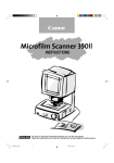
Thank you for purchasing this Canon Microfilm Scanner
800.
The Microfilm Scanner 800 is a desktop universal microfilm scanner that features a large A3-format screen. Images
projected on the screen can be output directly to a dedicated printer connected to the scanner or downloaded as
image data onto a computer connected to the scanner.
Optional carriers provide support for a wide variety of film
types, including roll film, microfiche and aperture cards.
Read the instructions in this manual carefully to ensure that
you make the best possible use of your scanner, and keep
this manual handy for future reference.
–1–
Introduction
Conventions Used in These
Instructions
The symbols and icons used in this manual are described
below. Take the time to read and understand this information before reading the rest of the manual.
(➞ 12)
A number preceded by an arrow and enclosed in parentheses indicates the number of the page on which you will
find more information about the preceding statement or
paragraph.
WARNING
Warnings are provided for your safety and contain
extremely important information. Failure to observe
the instructions provided in a warning could result in
death or serious injury to yourself or your co-workers.
CAUTION
Caution notices are also provided for your safety and
contain important information. Failure to observe the
instructions provided in a caution notice could result in
serious injury to yourself or your co-workers or damage to the equipment.
IMPORTANT
These important notes contain important information
on procedures that must be followed or actions that
must be avoided. Failure to observe a request could
result in damage to the equipment or a malfunction.
Notes
Notes provide additional tips or advice that can save
you time and effort in using the scanner.
–2–
Contents
Contents
Introduction ...................................................... 1
Selecting the Scan Size ......................... 26
Setting the Scanning Position ................ 26
Conventions Used in These Instructions ............ 2
Contents ............................................................ 3
Before You Begin... ........................................... 4
Trimming/Border settings ....................... 27
Special Features ............................................. 28
Storing the Lens Magnification ......................... 28
Storing a Zoom Setting .......................... 28
Safety Notes ....................................................... 4
Function Keys ................................................... 29
Choosing a Safe Location .................................. 4
Programming Function Keys .................. 29
Power Supply ..................................................... 6
Functions that Can Be Assigned to the
Important Warnings ............................................ 7
Function Keys ........................................ 30
Features ............................................................. 9
Function Key Labels .............................. 32
Operation Modes .............................................. 10
“Add on” Setting ............................................... 33
Checking the Box Contents .............................. 11
Setting the Add On ................................ 33
Important Components and Their Functions .... 12
Setting the Caption ................................ 35
Optional Products ............................................. 13
Setting the Date and Time ..................... 36
Preparing the Carrier ....................................... 14
Setting the Auto Clear Time ............................. 38
Lenses .............................................................. 15
Fitting and Replacing Lenses ................ 15
Preparing the Printer ........................................ 16
Connecting to a Computer ............................... 17
Connecting the Computer ...................... 17
Maintenance and Troubleshooting ............... 39
Replacing the Lamp ......................................... 39
Routine Cleaning .............................................. 41
Cleaning the Screen and Main Unit ....... 41
Device Drivers ........................................ 17
Using the Operation Panel Keys ...................... 18
Operation Panel ..................................... 18
Operation Keyboard (optional) ............... 19
Using the Scanner .......................................... 20
Cleaning the Lens .................................. 41
Cleaning Mode ................................................. 42
Cleaning the Fuser Roller ...................... 42
Troubleshooting ................................................ 43
Automatic Border Removal and Skew
Correction ......................................................... 44
Switching On .................................................... 20
User Call Errors ................................................ 45
Switching Off .................................................... 20
Service Call Errors ........................................... 46
Loading the Film ............................................... 20
Adjusting the Image ......................................... 21
Focusing the Image ............................... 21
Enlarging and Reducing the Image ....... 22
Specifications ................................................. 47
Index ................................................................ 48
Rotating the Image ................................ 22
Printing or Scanning the Image ........................ 23
Selecting the Polarity ............................. 23
Brightness Adjustment ........................... 24
Selecting the Paper for Printing ............. 25
–3–
Before You Begin...
Before You Begin...
Safety Notes
To ensure safe operation, read the following precautions
and recommendations before you choose a location and set
up the scanner.
;;;;;;
;;;;;;
;;;;;;
;;;;;;
150mm
100mm
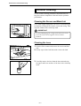
Choosing a Safe Location
❏ To ensure adequate space for operation, maintenance
and ventilation, ensure that there is ample space around
the scanner on all sides.
300mm
;;;;;;;
;;;;;;;
;;;;;;;
;;;;;;;
;;;;;;;
;;;;;;;
;;;;;;;
;;;;;;;
;;;;;;;
;;;;;;;
;;;;;;;
;;;;;;;
;;;;;;;
;;;;;;;
;;;;;;;
;;;;;;;
❏ Avoid locations exposed to direct sunlight.
When direct sunlight is unavoidable, use curtains to
protect the scanner.
❏ Avoid dusty locations.
Dust can adversely affect internal scanner components.
❏ Avoid locations close to taps, water heaters or humidifiers where the scanner would be exposed to high temperatures or moisture.
❏ Avoid locations affected by fumes from ammonia,
acetone or other volatile chemicals. Never use any kind
of volatile or flammable spray or aerosol near the
scanner.
–4–
Before You Begin...
;;;;;;;
;;;;;;;
;;;;;;;
;;;;;;;
;;;;;;;
;;;;;;;
;;;;;;;
;;;;;;;
;;;;;;;
;;;;;;;
;;;;;;;
;;;;;;;
;;;;;;;
;;;;;;;
;;;;;;;
;;;;;;;
;;;;;;;
;;;;;;;
;;;;;;;
;;;;;;;
;;;;;;;
;;;;;;;
;;;;;;;
;;;;;;;
;;;;;;;
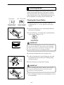
❏ Never set up the scanner in locations where flammable
substances such as alcohol, paint thinners or other
organic solvents are present.
❏ Always set up the scanner on flat and stable surface that
can support the weight of the scanner (47 kg).
❏ Choose a location that is free of excessive vibration.
❏ Avoid locations that are subject to extreme or sudden
changes in temperature.
Condensation formed inside the scanner can adversely
affect print quality. The temperature and humidity
ranges for optimum scanner operation are as follows:
Temperature: 10°C to 32.5°C (50°F to 90.5°F)
Humidity: 10% to 85% RH (condensation free)
❏ Do not set up the scanner close to equipment that can
generate strong magnetic fields, such as speakers, radios
or televisions.
–5–
Before You Begin...
;;;;;;;
;;;;;;;
;;;;;;;
;;;;;;;
;;;;;;;
;;;;;;;
;;;;;;;
;;;;;;;
;;;;;;;
;;;;;;;
;;;;;;;
;;;;;;;
;;;;;;;
;;;;;;;
;;;;;;;;
;;;;;;;
;;;;;;;;
;;;;;;;;
;;;;;;;;
;;;;;;;;
;;;;;;;;
Power Supply
❏ Power should always be supplied from a rated power
outlet.
❏ Do not place objects on the power cord and position the
cord so that it will not be stepped on by people working
around the scanner.
❏ Do not bundle the power cord or wrap it around objects
such as table or chair legs.
❏ Do not attempt to unplug the scanner by pulling on the
power cord. Grasp the plug itself firmly to remove it.
To ensure safe operation, always ground the scanner.
Note that the scanner should never be grounded by
connecting the ground lead to a gas or water pipe.
If you are unsure of any aspects of the power supply,
consult your authorized Canon dealer or your power
supplier.
–6–
Before You Begin...
Important Warnings
WARNING
● Always observe these warnings when using the
scanner. Failure to follow these warnings could
result in injury due to fire or electric shock.
● Do not set up the scanner in a location close to
flammable solvents such as alcohol and paint
thinners.
● Do not cut, damage or modify the power cord, do not
pull or bend the power cord excessively, and do not
place heavy objects on the power cord.
● Never plug in or unplug the power cord with wet
hands.
● Do not place objects on top of the scanner as such
objects could fall and cause injury. Do not plug the
scanner into a multi-socket adapter.
● Do not knot or bundle the power cord, and ensure
that the plug is pushed fully into the power outlet.
● Use only the power cord supplied with the scanner.
● Do not attempt to disassemble or modify the scanner. There are no user-serviceable parts inside the
scanner.
● Do not use flammable sprays or aerosols near the
scanner.
● Switch the scanner off and unplug the power cord
before cleaning the scanner.
● To clean the unit, use a cloth lightly dampened with
water or a mild detergent.
● If the scanner emits an unusual noise, odor, smoke or
sparks, or if the scanner will not function when
switched on, immediately switch the scanner off,
unplug the power cord and contact an authorized
Canon dealer or service center.
● Before you move the scanner even a short distance,
switch the scanner off and unplug the power cord.
–7–
Before You Begin...
CAUTIONS
● Do not set up the scanner on sloping, wobbly or
otherwise unstable surfaces or in locations affected
by excessive vibration. The scanner could cause
injury if it falls over or slides off the surface.
● Do not block the ventilation slots as this could result
in a fire due to the build up of heat inside the scanner.
● Do not place vessels containing liquids (cups, vases,
etc.) or small metal objects (paper clips, staples,
necklaces, etc.) on top of the scanner. Liquids or
metal objects falling into the scanner could cause an
electric shock or fire. If any liquids or metal objects
fall into the scanner, immediately switch the scanner
off, unplug the power cord and contact an authorized Canon dealer or service center.
● Do not set up the scanner in dusty or humid
locations as this could result in an electric shock or
fire.
● Do not place heavy objects on top of the scanner as
such objects could fall and cause injury.
● Use only a power supply having the rated voltage.
The use of other voltages could result in a fire or
electric shock.
● Always unplug the power cord by grasping the plug
itself. Pulling on the power cord can damage the
cord so that the core wires are exposed or snapped
and could cause a fire or electric shock.
● Do not use an extension power cord as this could
cause a fire or electric shock.
● Keep the area around the power outlet free of obstacles to ensure that the scanner can be unplugged
quickly in the event of an emergency.
● Take care not to tip water or flammable solvents
such as alcohol, thinners or benzene into the scanner
as this could result in a fire or electric shock.
● If the scanner will be left unused for a lengthy
period, always unplug the scanner as a safety measure.
● Avoid touching internal scanner components when
you perform routine cleaning or maintenance such
as changing the lamp. Some internal components
generate high temperatures or high voltages. To
avoid injury such as burns or electric shocks, take
care also that metal objects such as necklaces or
bracelets do not come into contact with internal
scanner components.
● To avoid injury when you are moving the scanner,
take care not to put your hands on the metal
protrusions on the underside of the scanner unit.
–8–
Before You Begin...
Features
The Canon Microfilm Scanner 800 features the following:
❏ Large-format screen, small footprint
Despite providing a large A3-size screen, this compact
universal microfilm scanner is small enough to fit on a
desktop.
❏ Automatic film selection
The scanner’s automatic film polarity detection function
saves you the trouble of switching the polarity when
you are scanning both negative and positive film.
❏ Support for different film formats
With its wide range of optional roll carriers, fiche
carriers and Auto Carriers, this scanner can handle a
wide variety of film formats, including microfiche,
aperture cards and roll film.
❏ Automated and motorized operation
Simple keystrokes can be used to control editing functions such as screen image adjustment and border
removal as well as other scanner functions.
❏ Different operation modes to suit your circumstances
The MS800 scanner has 2 operation modes:
“ReaderPrinter mode”, in which the image on the screen
is sent directly to a dedicated printer, and “Scanner
mode”, in which the scanner is connected to a personal
computer and the scanned image data is downloaded to
the computer. You can select whichever mode best suits
your needs. The operation mode is set by the service
technician at installation. See “Operation Modes” on
P.10 for more information.
–9–
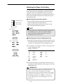
Operation Modes
The MS800 scanner has 2 operation modes: “Reader/Printer mode”, in which the image on the
screen is sent directly to a dedicated printer, and “Scanner mode”, in which the scanner is connected
to a personal computer and the scanned image data is downloaded to the computer to be printed on
a printer connected to the computer. The connected devices and operation procedures for the two
modes differ. Select the mode that best matches your system setup.
The operation mode is set by the service technician at installation. Contact your authorized Canon
service representative for details.
❏ Reader/Printer mode
This configuration consists of the Microfilm Scanner 800 with a FilePrint 400 printer. Screen images are sent
directly to the FilePrint 400 using the control panel on the Microfilm Scanner 800. To switch from this mode
to Scanner mode, contact your Canon service technician.
Print
File Print 400
Microfilm Scanner 800
❏ Scanner mode
This configuration consists of the Microfilm Scanner 800 with a computer and printer. Application software is
used to download screen images to the computer connected to the Microfilm Scanner 800 as image data. The
downloaded image data can then be sent to the printer connected to the computer. To switch from this mode to
ReaderPrinter mode, contact your Canon service technician.
Print
Picture deta
Computer
Printer
Microfilm Scanner 800
❏ Reader/Printer/Scanner mode (factory default):
Select this mode when you want to use both Reader/Printer mode and Scanner mode. You switch
between the two modes by assigning a switching function to one of the function keys. This mode
also allows you to use the MS 800 as a scanner in Reader/Printer mode and scan images from
your computer. However, you should switch to Scanner when you want to scan from the computer since some scanner keys cannot be used in Reader/Printer mode.
Reader Printer mode
Print
Scanner mode
Picture deta
Print
Computer
FilePrint 400
Microfilm Scanner 800
– 10 –
(Printer)
Before You Begin...
Checking the Box Contents
The Microfilm Scanner 800 package contains the items listed below. If any of these items is missing, contact your Canon service outlet for assistance.
Microfilm Scanner 800
INSTR
UCTIO
Lens holder
NS
INSTR
UCTIO
NS
INSTR
UCTIO
NS
ENGLIS
H
Be sure
Keep thisto read this
instruction instruction
s on hand s before
you use
for reference
the
to ensureequipment.
optimum
performan
ce
ENGLIS
H
Be sure
to
Keep this read this instructions
instructions
on hand before you use
for reference
the equipment.
to ensure
optimum
performanc
e
Microfilm Scanner 800
Instructions
Scanning Utility 800
Instructions
ISIS/TWAIN Driver
Instructions
Setup CD-ROM
Software Licence
Agreement
Warranty Card
Function key labels
Power cord
– 11 –
(USA and Canada only)
Before You Begin...
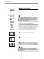
Important Components and Their Functions
Take a few moments to familiarize yourself with the names and functions of the main components
of the scanner, as described below.
1
2
8
3
4
9
7
6
5
1 Screen
Shows enlarged projections of the images on
the microfilm.
7 DIN connector
Use this socket to connect a motorized carrier
(optional).
2 Framing Kit (optional)
When a specified area is to be scanned, use
this cursor to set the size of the scanned area.
8 Operation panel
Use these buttons to specify the image adjustment and operation mode settings.
3 Lens holder
Holds the lens.
9 Operation keyboard (optional)
Provides easy access to all the operation panel
controls.
4 Lamp unit
Holds the lamp that illuminates the image.
Remove this unit to change the lamp.
!º Foot switch (optional)
An underfoot switch that provides the same
function as the Start key on the operation
panel.
5 Carrier pad
Holds the film carrier.
6 Power switch
Switches the scanner on and off.
– 12 –
Before You Begin...
Optional Products
In addition to the accessories provided in the product
package, a number of optional accessories that are required
for using the scanner, such as carriers and lenses, are also
sold, as well as other optional accessories that can be
purchased as needed. Contact your nearest authorized
Canon Dealer for details.
Carriers (➞ 13 “Preparing the Carrier”)
Carriers can be used for all types of film, including cartridge film, microfiche, jacket film and aperture cards.
Because the scanner does not come with a carrier, purchase
the carrier best suited to your needs.
Installation Kit (➞ 13 “Preparing the Carrier”)
Some carriers require the Installation Kit. Contact your
nearest authorized Canon service outlet for details.
Lenses (➞ 14 “Lenses”)
One fixed-focus lens and four zoom lenses are provided for
the MS 800. Because the scanner does not come with a
lens, purchase the lenses best suited to your needs.
Framing Kit (➞ 25 “Trimming/Border settings”)
This unit allows you to select a part of the image projected
onto the scanner screen (trimming). This Framing Kit is
required in order to use the Trimming function provided in
the scanner.
Operation Keyboard (➞ 16 “Using the Operation
Panel Keys”)
This keyboard provides a handy way to access the functions provided on the operation panel.
Foot Switch
This is an underfoot switch that provides the same function
as the Start key on the operation panel.
128MB Additional Memory
To scan in grayscale mode from the application software
additional memory must be installed in the scanner.
Contact your nearest authorized Canon Dealer for details.
FilePrint 400 (➞ P.15 “Preparing the Printer”)
A dedicated printer for the Microfilm Scanner 800 when it
is used in Reader Printer mode.
– 13 –
Before You Begin...
Preparing the Carrier
The list below shows all the optional film carriers that can
be installed on the Canon Microfilm Scanner 800. For
more details about these optional carriers, consult your
Canon dealer or authorized Canon service outlet. For
information on carrier installation and operation, refer to
the instructions provided with the carrier.
Note
The Auto Carrier 100C, 100M and 100R and the FS
Controller I and Roll/Fiche Carrier 200 require the
optional installation kit.
Fiche Carrier 190R II
A film carrier for viewing microfiche (up to 105 x 190
mm), jackets and aperture cards.
Auto Carrier 100C (AC100C)
A motorized automatic carrier for 16 mm cartridge film
(ANSI, ANSI ENCLOSED *1, Kodak Ektamate or 3M)
that features high-speed automatic loading and rapid film
feeding and display.
Auto Carrier 100M (AC100M)
A motorized automatic carrier for 3M cartridges or
TUSCAN M-type *2 cartridges that features high-speed
automatic loading and rapid film feeding and display.
Auto Carrier 100R (AC100R)
A motorized automatic carrier for 16 or 35 mm film wound
on standard open reels.
FS Controller I
A motorized automatic carrier for 16 mm cartridge film
(ANSI, Kodak Ektamate or 3M). This carrier is required
for reading film marked with blips for image search and
retrieval.
FS Controller III
A motorized automatic carrier for the latest 16 mm cartridge film (ANSI, Kodak Ektamate or 3M). This carrier is
required for reading film marked with blips for image
search and retrieval.
Roll/Fiche Carrier 200
This carrier is required for reading 16 or 35 mm standard
open reel film, 16 mm cartridge film (ANSI, Kodak
Ektamate or 3M), microfiche (up to 105 x 190 mm),
jackets or aperture cards.
*1 ANSI ENCLOSED cartridges are as stipulated in ANSI MS-15.
*2 TUSCAN M-type refers to TUSCAN cartridges with a 3M-type core.
– 14 –
Before You Begin...
Lenses
The types of lenses that can be used with this scanner are
described below.
Fixed-focus Lenses
GZ X57 (57x)
Zoom Lenses
GZ X7-X7.5 (7x to 7.5x)
GZ X9-X16 (9x to 16x)
GZ X14-X30 (14x to 30x)
GZ X20-X50 (20x to 50x)
Fitting and Replacing Lenses
Use the procedure below to fit or change the lens.
1 Grasp the lens holder firmly and slide it out of the lens
holder bracket.
2 If a lens is already fitted in the holder, use one hand to
support the base of the lens holder, taking care to ensure
that the lens does not fall out.
– 15 –
Before You Begin...
4 Slowly set the lens in the lens holder.
IMPORTANT
When you are fitting a zoom lens, check that the 2
marks on the rim of the lens are matched with the
contacts on the lens holder. These contacts must be
aligned snugly for the scanner to correctly recognize
the zoom lens type. Take care also not to touch the
contacts with your fingers.
5 Slide the lens holder back into the main unit, taking care
not to drop the lens.
Push the holder slowly into the bracket until you hear it
click into place.
Preparing the Printer
To use the Microfilm Scanner 800 in ReaderPrinter mode,
a Canon FilePrint 400 printer (sold separately) is required.
Contact an authorized Canon retailer or service technician
for details.
NOTE
Canon FilePrint 400
Refer to the FilePrint 400 Instructions for information on setting up the printer.
– 16 –
Connecting to a Computer
To use the Microfilm Scanner 800 in Scanner mode, you
will need the following equipment in addition to the
accessories provided with the scanner:
• Computer
• SCSI card
• SCSI cable
IMPORTANT
No SCSI cable is supplied with the scanner. To
connect the scanner to a computer, obtain a SCSI
cable with the correct connectors for the scanner and
the SCSI card installed in the computer. The SCSI
connector on the scanner is a half-pitch 50-pin
connector (pin-type).
Connecting the Computer
Connection of the SCSI cable to the main unit and the
specification of the SCSI ID and other settings should be
done by the supervising service personnel. To change the
SCSI ID or any other connection settings, contact the
service person.
Note
At shipment, the SCSI ID for the scanner is set to 2
and the terminator setting is OFF.
Device Drivers
If the computer is running the Windows 95/98, a screen
requesting installation of the scanner driver (“New Hardware” or “Device Driver Wizard”) will appear the first
time you switch the computer on after connecting the
scanner to the computer. In the “New Hardware” screen,
choose “Select from list” and click “OK”. In the next
screen, select “Other devices” and click “OK”.
In the “Device Driver Wizard” screen, click “Next” and
then click “Completed” in the next screen.
– 17 –
Before You Begin...
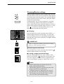
Using the Operation Panel Keys
Operation Panel
M1
F1
F2
M2
F4
F5
ZOOM
F3
F6
AE
M3
AF
FOCUS
ROTATE
1 Function keys
Settings such as printing or scanning parameters and
operation modes can be stored in a function key and the
stored operation mode recalled instantly simply by pressing the function key. Settings are stored in a function key
using the application software or by programming the
function key (➜ P.29).
2 Negative/Positive key
Selects one of three modes: Positive prints from negative
film, positive prints from positive film, or automatic film
polarity detection.
3 Trimming/Border key
When scanning or printing, use this key to trim part of the
image or to remove the black border around the image.
4 Scanning Position key
Used to specify whether the reference position for scanning
or printing is the center of the screen or the left edge. This
key is also used to specify scanning of 2 consecutive
pages.
5 Paper Select/Scan Size key
In Reader Printer mode, this key selects the paper size used
for printing. In Scanner mode, this key selects the scan
size.
6 Brightness indicator
Shows the brightness adjustment set using the Brightness
keys or the setting for adjustments such as the margin size
or sharpness.
7 Brightness adjustment keys
The and keys are used to manually adjust the brightness of the printed or scanned image. The AE key specifies
automatic adjustment.
8 Error/User Mode display
Displays an error message (user call or service call) or the
selected user mode. This display also shows the number of
copies in ReaderPrinter mode.
9 User Mode keys
Selects the user mode and can be used to set the number of
copies in ReaderPrinter mode.
!º Clear/Stop key
Used to stop scanning or printing and to change the user
mode setting.
!¡ Start key
In Reader Printer mode, the Start key starts printing. In
Scanner mode, this key starts a scan in Semi-Auto mode.
!™ Preset Zoom keys
These keys are used to store the magnification settings for
zoom or fixed-focus lenses and to automatically adjust the
scanner to the stored magnification.
– 18 –
Before You Begin...
!£ AF (Auto Focus) key
Used to automatically focus the image.
!¢ ZOOM (enlarge/reduce) key
Used to enlarge or reduce the size of the image projected
on the screen. Press the ZOOM key and then use the
control knob to enlarge and reduce the image on the screen.
FOCUS key
Adjusts the focus of the image projected on the screen.
Press the FOCUS button and then turn the control knob
until the image on the screen is in focus.
!§ ROTATE key
Rotates the image projected on the screen. Press the
ROTATE key and then turn the control knob. The image
rotates to match the rotation of the control knob.
!¶ Control knob
Turn this knob to adjust the image after the ZOOM, FOCUS or ROTATE key has been pressed.
Operation Keyboard (optional)
P2
P3
P4
!• Image adjust selection key
Selects the image adjustment mode (zoom, focus or rotate).
!ª Image adjust mode indicators
These indicators show the image adjustment mode selected
using key !•.
@º Image adjust control dial
After selecting the image adjustment mode, turn this dial to
adjust the image.
@¡ Rotate key
Rotates the image 90° clockwise or counterclockwise.
@™ Film control knob
When a motorized carrier is installed, this knob feeds
through the film. Turn the knob to the right to advance the
film and to the left to rewind the film. (Note that this knob
cannot be used with the FS Controller I or III.)
@£ RESET key
Restores the default settings for each setting mode.
@¢ Paper Select key
Selects the paper cassette or multipurpose tray in
ReaderPrinter mode.
Disabled key
Not used by the MS800.
– 19 –
Using the Scanner
Using the Scanner
Switching On
Use the procedure below to switch the scanner on.
IMPORTANT
If an FS Controller III is installed on the scanner,
switch the FS Controller III on first.
1 Press the “|” side of the power switch to turn on the
main unit. When the main unit is switched on, the Start
key glows red and the scanner switches.
(In ReaderPrinter mode: Green. In Scanner mode: Red)
2 Switch on the computer and printer.
IMPORTANT
Switch on any SCSI devices connected to the computer before you switch on the computer.
Switching Off
1 Switch off the computer and printer.
2 Press the “o” side of the power switch to switch the
scanner off.
IMPORTANT
If the scanner will not be used for a lengthy period,
unplug the power cord as a safety measure.
Loading the Film
Because film loading methods differ for each carrier, refer
to the instructions provided with the carrier for information
on how to load the film.
– 20 –
Using the Scanner
Adjusting the Image
The instructions below describe how to adjust the image
projected onto the scanner screen.
Note
The image can be adjusted using the operation panel
below the screen or the optional operation keyboard.
Focusing the Image
The image projected on the screen can be focused either
automatically (Auto Focus) or manually.
Auto Focus
1 Check that the AF key on the operation panel is lit.
AF key
Control knob
• Auto Focus does not function when the AF key is unlit.
2 Press the AF key.
• If you press the AF key when it is lit, the image sensor
moves to automatically adjust the focus before returning
to its original position.
• The AF key flashes during auto focusing.
Note
AF operates more easily when the image projected on
the screen is rotated slightly so that it appears
skewed.
AF operates more successfully when the image
projected on the screen is rotated slightly so that it
appears skewed.
FOCUS key
IMPORTANT
AF may not operate normally for some images. In
this event, focus the image manually or retry auto
focusing.
Image adjust
mode indicators
Manual Focus
1 Press the FOCUS key.
2 Turn the image adjustment control knob left or right to
focus the image.
Image adjustment
selection key
image adjustment
control dial
Note
To adjust the focus using the operation keyboard,
press the image adjustment selection key to select the
mode (the ZOOM, FOCUS or ROTATE mode indicator lights) and then use the image adjustment control
dial to adjust the image.
(Operation keyboard)
– 21 –
Using the Scanner
Enlarging and Reducing the Image
ZOOM key
Control knob
1 Press the ZOOM key.
2 Turn the image adjustment control knob to enlarge or
reduce the image. Turn the knob to the left to enlarge
the image and to the right to reduce it.
• If you are using the optional operation keyboard, press
the image adjustment selection key until the ZOOM
indicator lights and then turn the image adjustment
control dial left or right to enlarge or reduce the image.
Turn the dial to the left to enlarge the image and to the
right to reduce it.
Note
Zoom ratios can be stored in the preset zoom keys so
that images can subsequently be enlarged or reduced
by the stored ratio at a single touch. (➜ P.28 “Storing
a Zoom Setting”)
Rotating the Image
● Rotation by any angle
Control knob
1 Press the ROTATE key.
2 Turn the image adjustment control knob to rotate the
image. Turn the knob to the left to rotate the image to
the left and to the right to rotate it to the right.
ROTATE key
• If you are using the optional operation keyboard, press
the image adjustment selection key until the ROTATE
indicator lights and then turn the image adjustment
control dial left or right. Turn the dial to the left to
rotate the image to the left and to the right to rotate it to
the right.
● 90° Rotation
When you are using the optional operation keyboard,
the image can be rotated left or right in 90° steps simply
by pressing the image rotation keys. Press the key to
rotate the image 90° to the left and the key to rotate it
90° to the right.
Note
The 90° rotation function can also be assigned to one
of the function keys on the operation panel. (➜ 27
“Function Keys”)
– 22 –
Using the Scanner
Printing or Scanning the Image
In Reader Printer mode, the image projected on the scanner
screen can be printed directly to a FilePrint 400 printer
connected to the scanner. In Scanner mode, the image can
be downloaded as image data to a computer connected to
the scanner and then printed on a printer connected to the
computer.
The actual scan settings and the procedure for the scanning
mode differ depending on your application program. For
this reason, the descriptions given here cover only the
scanning modes that can be set from the scanner’s operation panel.
Refer to the user manuals for your application software for
information on the scan settings and the procedure for
downloading the image.
Selecting the Polarity
This setting selects the film polarity (positive or negative).
Press the Negative/Positive key on the operation panel or
the optional operation keyboard to select the film polarity.
(
) Negative Positive output from negative film
(
) Positive
( A ) Auto
Positive output from positive film
The scanner automatically detects the film
type and generates positive output. When
the Auto setting is selected, the Negative or
Positive indicator blinks during scanning to
indicate the film type.
Notes
• If the black-white ratio in the screen is almost even,
if the image border is small, or if you have used
trimming to select an area at the edge of the image,
the scanner may be unable to automatically detect
the film type. In this event, select the film polarity
manually.
• If you select Positive, border removal (➜ P.27) and
automatic skew correction (➜ P.30) are disabled.
– 23 –
Using the Scanner
Brightness Adjustment
Use the procedures described here to adjust the image
brightness during scanning or printing. The brightness can
be adjusted either automatically (AE) or manually.
● Automatic adjustment
Press the AE key on the operation panel or the operation
keyboard (sold separately). The AE key lights and the
image brightness is adjusted automatically during
scanning.
Note
When automatic adjustment is selected, you can
make fine adjustments to the brightness through 17
levels by pressing the brightness adjustment keys (
and ).
Moving the indicator to the right brightens the image
by fine increments, and moving it to the left darkens
the image by fine increments.
● Manual adjustment
When the AE key is lit, you can use the brightness adjustment keys ( and ) to adjust the brightness of the scanned
image. Moving the indicator to the right brightens the
scanned image and moving it to the left darkens the
scanned image.
Note
In manual adjustment, the brightness can be adjusted
through 33 levels, as shown in the figure at left.
– 24 –
Selecting the Paper for Printing
Use the procedures described here to select the paper size
in the paper cassette or multipurpose tray when you are
using the scanner in ReaderPrinter mode. To select the
paper size for a paper cassette, use the Paper Select key on
the optional operation keyboard or the Scan Size key on
the operation panel.
● Selecting the paper feed cassette
Multipurpose tray
Upper cassette
Lower cassette
(120V model)
• On the optional operation keyboard, press the Paper
Select key and select the paper cassette.
• On the operation panel, press the Scan Size key and
select the paper loaded in the printer.
NOTE
If same paper size is loaded in the paper cassette and
the multipurpose tray, refer to the printer display
panel to determine whether the paper cassette or
multipurpose tray will be used.
● Selecting paper for the multipurpose tray
1 Hold down the Scan Size key or the Paper Select key on
(220 – 240V model)
the optional operation keyboard for 5 seconds to switch
to paper size setting mode for the multipurpose tray.
2 Use the plus (+) and minus (-) keys to set the paper size
for the multipurpose tray.
Display Paper Size
(120V model)
(220 – 240V model)
Legal
A3
Letter
A4
Letter-R
A4R
Ledger
Statement
3 Press the Scan Size key or the Paper Select key on the
optional operation keyboard to set the paper size for the
multipurpose tray.
IMPORTANT
Always check that the paper size displayed for the
paper cassette and the multipurpose tray paper
setting match the paper actually loaded. If the loaded
paper does not match the setting, an “L8” error will
be displayed. However, if “STMT” is selected, no
error is displayed since the STMT paper size is not
supported.
– 25 –
Using the Scanner
(120V model)
Selecting the Scan Size
If image size detection is set to ON in the application
program in Scanner mode, select the scan size.
Press the Scan Size key on the operation panel and set the
scan size.
(220 – 240V model)
Note
If image size detection is set to OFF in the application software or trimming/border removal is selected,
the Scan Size selection function light switches off
and the function is disabled.
Setting the Scanning Position
If an image is too big, you can select a specific area to be
scanned by pressing the Scanning Position key. The indicator for the currently selected mode lights when the key is
pressed and the setting changes each time the key is
pressed. Press the key until the desired mode lights.
A 3/ A 4
A 3/ A 4
A4 R
A4
A4 R
A4
A4
A4 R
A4
(
) The central area of the screen is scanned.
(
) The left side of the screen is scanned.
A3
A4 R
A3
( ) The left and right sides of the screen are scanned as 2
consecutive images. Because the left side is scanned first,
it is not necessary to reverse the sequence of printed pages.
A 3/ A 4
A4 R
A4
A4
A4 R
A3
Note
If trimming is selected in Scanner mode, the center
(
) and left edge (
) reference positions cannot
be selected.
– 26 –
Using the Scanner
Trimming/Border settings
;;;;
;;;;
;;;;
;;;;
;;;;
When an image on negative film is scanned and projected
onto the scanner screen, the area outside the image appears
as a black border around the image. The Automatic Border
Removal function can be used to remove this black border
around the scanned image.
Trimming allows you to restrict scanning to a specified
area of the image. Border removal allows you either to
remove all the black border around the image or to leave a
narrow black margin around the image. However, if “Positive” ( ) is selected as the film polarity (➜P.23), the
border removal function does not operate.
● Trimming
Press the Border key on the operation panel until the ( )
indicator lights and then scan the image. To specify the
area to be trimmed, move the tabs along the bottom edge
and right side of the screen so that they are aligned with the
lines on the screen.
IMPORTANT
Adjust or change the trimming area before scanning
begins or while scanning is paused.
● Removing the entire border
Press the Border key on the operation panel until the (
indicator lights and then scan the image.
)
● Leaving a margin around the image
Press the Trimming/Border key on the scanner’s front
panel to switch on the ( ) lamp and scan the image. The
size of the margin is set either from the application software or by storing the setting in a function key (➜ P.31).
Notes
• Border removal may not operate correctly for
images with ill-defined borders.
• This function cannot be used when any part of the
image is outside the specified range.
• If multiple images are displayed on the screen at
the same time, the wrong image may be scanned.
• This function can only operate if there is a clear
area of at least 5 mm around the image.
– 27 –
Special Features
Special Features
This part of the manual describes the many convenient scanner features and settings that can enable
you to use the scanner more effectively.
Storing the Lens Magnification
You can use the preset zoom keys (M1, M2 and M3) on the
operation panel to store the zoom settings used on zoom
lenses and then recall a stored zoom setting with a single
touch.
Storing a Zoom Setting
M1
M2
M3
1 Adjust the zoom to the required setting on the screen.
2 Hold down the preset zoom key to be used to store the
setting for 2 seconds.
3 The zoom lens operates and the preset zoom key blinks.
4 The zoom key stops blinking and remains lit to indicate
that storage of the zoom setting is completed.
5 In normal operation, pressing a lit preset zoom key
automatically enlarges or reduces the image to the
stored lens magnification.
Note
Preset zoom settings can be stored separately for 4
types of zoom lens. When a zoom lens for which a
zoom setting has been stored is fitted, the corresponding preset zoom key lights.
Zoom settings can be stored in the preset zoom keys
on the optional operation keyboard as well as in the
zoom keys on the operation panel, making a total of 6
preset zoom keys. However, because there are no
indicator lamps in the preset zoom keys on the
operation keyboard, you should make a note of the
key numbers and the stored settings if you store
zoom settings in these preset zoom keys.
If preset zoom key registration fails, “L6” appears on
the Error/User Mode display (➜ P.45). If this occurs,
press the Clear key to clear the error display and retry
the preset zoom key registration.
– 28 –
Special Features
Function Keys
The function keys (F1 to F6) on the operation panel can be
used to store frequently used functions, allowing the preset
function to be recalled at a single touch. The function keys
(F1 to F6) can store up to 6 function settings. (If the optional operation keyboard is used, an additional 4 settings
can be stored.) The nineteen types of settings that can be
stored are described below.
Programming Function Keys
Use the procedure below to store a function in a function
key.
1 Hold down the Clear key and the function key you want
to program for 2 seconds.
• The number of the function to be stored appears on the
display.
+
F1
F2
F3
F4
F5
F6
Display Function
All setting Assignment
New File
Lighten Screen
Darken Screen
Standby mode
Rotate Right
Rotate Left
Skew Correction
Addon
margin Scanning
Adjust Margin
Adjust Sharpness
Picture Mode
Overlay Scanning
600DPI
Background erase
Auto centering
Scanner
Printer
or
P1
P2
P3
Use the function keys
P4
(Optional keyboard)
F1
F4
F5
F6
F3
F2
P1
P3
P4
P2
F1
F4
• See the following pages for descriptions of the functions.
• At shipment, P1 and P4 are assigned to the optional
operation keyboard.
2 Use the selector keys (the plus and minus keys) to select
the function assigned to the function key.
3 Press the function key to store the function.
Note
Function keys can also be programmed from the
application software. Refer to the manuals supplied
with the application for details.
– 29 –
Special Features
Functions that Can Be Assigned to the
Function Keys
The functions described below can be assigned to a function key.
● Assign all settings
This function stores the operation panel status and all
the scan settings.
● New file
After you have pressed this key, the scanned image is
saved into another file (folder). For the details, see the
Users’ Manual for your application.
● Raise screen brightness
This function raises the screen brightness.
● Lower screen brightness
This function lowers the screen brightness.
● Standby (default setting: F6)
Sets the equipment to Standby state. Projection on the
screen will be turned off, and standby display will
appear. You can release the standby state by pressing
the key again or by operating other key.
● Rotate 90° right (default setting: F2)
This function rotates the screen image 90° to the right.
● Rotate 90° left (default setting: F3)
This function rotates the screen image 90° to the left.
;;;;
;;;;
;;;;
;;;;
;;;;
● Automatic skew correction
This function corrects a skewed image during scanning
so that it is scanned straight. However, if “for Positive
film” ( ) is selected as the film polarity (➜P.23), the
Auto Deskew Image function does not operate.
● Add on (default setting: P1)
Pressing this key imprints the add on specified on the
scanner (➜ P.33) or specified in the application on the
scanned image. Refer to the user manual supplied with
the your application software for information on the
application add on settings.
– 30 –
Special Features
● Import margins
This function selects whether the margins are adjusted
during scanning.
● Adjust margins (default setting: P3)
This function adjusts the margin size when margins are
scanned during scanning. When you press this key, the
display shows the margin size. The margin can be
adjusted to a value between –10 mm and 10 mm either
side of 0.
● Adjust sharpness (default setting: P4)
This function selects the sharpness (edge enhancement)
during scanning. When you press this key, the display
shows the sharpness setting. The sharpness can be set to
5 levels between 1 and 5.
● Photo mode (default setting: F5)
This key switches the mode to picture mode. When this
key is pressed, the key lights and the scanning mode
changes to “Monochrome Photo”.
11x17/ LTR
LGL
LTR R
LTR /STMT
STMT/LTR
LTR R
LGL
11x17
(Positions image B on top)
(Positions image B on the bottom)
● Import overlay
When you press this key, the 2 images in the A and B
positions on duplex film are output one above the other
as a single image during scanning.
When you store this function and hold down the function
key for 2 seconds, the position setting display for the 2
images is shown and the programmed function key and
setting display blink.
Use the (+) and (-) keys to change the setting and the
programmed function key to confirm the selected setting.
● 600 DPI
This switches the scanning resolution between 600 and
300 dpi. When you press this key, or when the resolution is set to 600 dpi from the application program, the
key lights up. Conversely, when this key is pressed
again and the key lamp switches off, the resolution in
the application software is set to 300 dpi.
– 31 –
Special Features
• Background Erase (default setting: P2)
Pressing this key automatically erases speckling in the
background of text, line drawings, etc. However, this
function is disabled in Scanner mode when the selected
scanning mode is “Grayscale” or “Monochrome Photo”.
• Auto Centering
In Reader Printer mode, this function prints the scanned
image in the center of the selected paper.
• Scanner mode (default setting: F1)
Pressing this key switches operation to Scanner mode.
• ReaderPrinter mode (default setting: F4)
Pressing this key switches operation to ReaderPrinter
mode.
NOTE
In Scanner mode, the functions assigned to function
keys can also include detailed settings specified by
the application program. Refer to the user manuals
for the application software for details.
Function Key Labels
Stick the enclosed function key labels above the programmed function keys.
(Function Keys)
– 32 –
“Add on” Setting
In ReaderPrinter mode, the Add on setting can be used to
specify a time, date or caption to be imprinted on the image
to be printed. Use the function key to select whether the
add on is imprinted on the image actually printed. (➜ P.29
“Function Keys”)
In Scanner mode, the Add on setting is specified from the
application software.
Setting the Add On
Use the procedure below to specify whether a preset caption (➜ P.35 “Setting a Caption”) or date (➜ P.36 “Setting
the Date and Time”) is to be imprinted on the image and to
set the location of the add on and the format of the date or
time.
1 Hold down the function key to which the Add on function is assigned for 2 seconds to switch to Add on
setting mode.
The number of copies indicator shows the Add on
setting.
NOTE
The left digit in the number of copies indicator shows
whether the date/time is imprinted (1) or not imprinted (0), while the right digit gives the same
information for the caption.
2 Use the minus (-) key to specify the date/time setting
and the plus (+) key to specify the caption setting.
Display Add on
Date/time and caption
Date/time only
Caption only
No add on
3 Press the Brightness adjustment key ( ) to switch to Add
on position setting mode. The copies indicator then
becomes the Add on position indicator.
4 Use the plus (+) and minus (-) keys to set the position of
the add on.
Display Add On Position
Top-left corner of the page
Top center of the page
Top-right corner of the page
Bottom-left corner of the page
Bottom center of the page
Bottom right of the page
– 33 –
5 Press the Brightness adjustment key ( ) to switch to
“Date/time format” setting mode. The copies indicator
then becomes the date/time format indicator.
6 Use the plus (+) and minus (-) keys to set the date/time
format.
Display Date/time Format
Add On Example
Year/Month/Day
2000/03/10
Year/Month/Day Hour:Minute
2000/03/10 11:30
Month/Day/Year
3/10/2000
Month/Day/Year Hour:Minute
3/10/2000 11:30
Day/Month/Year
10/3/2000
Day/Month/Year Hour:Minute
10/3/2000 11:30
Year Month Day
Mar 10 2000
Year Month Day Hour:Minute
Mar 10 2000 11:30
Day of the week Month Day Year Fri Mar 10 2000
Day of the week
Month Day Year Hour:Minute
Fri Mar 10 2000 11:30
7 When you have finished the settings, press the function
key to which the Add on function is assigned to complete the setting procedure.
– 34 –
Setting the Caption
This function adds a pre-registered caption to the printed
image. Registered captions can include up to 33 characters
(including spaces) selected from the character code table
shown below.
Code
20
Character
21 22 23 24 25 26 27 28 29 2A 2B 2C 2D 2E 2F
!
"
#
$
%
&
'
(
)
*
+
,
–
.
Code 20 inserts a space.
/
Code
30 31 32 33 34 35 36 37 38 39 3A 3B 3C 3D 3E 3F
Character
0
Code
40 41 42 43 44 45 46 47 48 49 4A 4B 4C 4D 4E 4F 50 51 52 53 54 55 56 57 58 59 5A
Character
@
Code
60 61 62 63 64 65 66 67 68 69 6A 6B 6C 6D 6E 6F 70 71 72 73 74 75 76 77 78 79 7A
Character
Code
Character
`
1
2
A
a
B
b
3
C
c
4
D
d
5
E
e
6
F
f
7
G
g
8
H
h
9
I
i
:
J
j
;
K
k
<
L
l
=
M
m
>
N
n
?
O
o
P
p
Q
q
R
r
S
s
T
t
U
u
V
v
W
w
X
x
Y
y
Z
z
5B 5C 5D 5E 5F 7B 7C 7D 7E
[
]
^
–
{
}
~
■ Setting the Caption
1 Hold down the function key to which the Add on
function is assigned for 2 seconds. The function key and
the Brightness indicator start blinking.
2 Hold down the AE key for 2 seconds.
The copies indicator now becomes the caption display
and the scanner switches to caption input mode.
3 Check that the lamp at the left end of the brightness
indicator is blinking and then press the plus (+) or
minus (-) key to set the character code for the first
character, as shown in the character code table.
4 Press the brightness adjustment key ( ) to indicate the
next character then use the plus (+) and minus (-) keys
to select the character.
5 Repeat the same procedure to register the rest of the
caption.
6 When you have finished registering the caption, press
the Reset key. The caption is then registered.
1st character
2nd character
3rd character
4th character
......
32nd character
NOTE
The position of the lamp in the Brightness indicator
shows which character in the caption is being set.
To clear the contents of the caption, press the Reset
key while you are in caption input mode. This clears
all the specified text.
33rd character
– 35 –
Setting the Date and Time
When the date and time are added to the scanned image in
Reader Printer mode, the date and time added are those set
internally on the scanner by this function. This section
describes how to set and check the date and time.
● Setting the Date and Time
+
1 Hold down the Clear key and the Negative/Positive key
for 2 seconds. The year figure blinks on the display and
you can start setting the date and time.
2 Check that the lamp at the left end of the brightness
indicator is blinking and then press the plus (+) or
minus (-) key to set the year.
Display
Setting
~
1951 to 1999
~
2000 to 2050
3 Press the brightness adjustment key ( ) to display the
month and then use the plus (+) and minus (-) keys to
set the month.
Display
~
AE
Setting
January to December
4 Press the brightness adjustment key ( ) to display the
day and then use the plus (+) and minus (-) keys to set
the day.
Display
~
Setting
1st to 31st
5 Press the brightness adjustment key ( ) to display the
time (24-hour format) and then use the plus (+) and
minus (-) keys to set the hour.
Display
~
– 36 –
Setting
00 to 23
6 Press the brightness adjustment key ( ) to display the
minutes and then use the plus (+) and minus (-) keys to
set the minutes.
Display
~
Setting
0 to 60 minutes
7 Press the brightness adjustment key ( ) to display the
seconds and then use the plus (+) and minus (-) keys to
set the seconds.
Display
~
Setting
0 to 60 seconds
8 When you have finished all the date and time settings,
press the Start key to complete the setting procedure.
● Checking the Date and Time
Year
Month
Day
1 When you press the Clear key and the Negative/Positive
key, the display changes to show the date and time in
the following sequence: Year ➜ Month ➜ Day ➜ Hour
➜ Minutes ➜ Seconds.
Hour
Minutes
Seconds.
NOTE
The position of the brightness indicator lamp identifies the date/time setting. If the scanner is set to
Scanner mode, the date and time set internally in the
scanner is reset to match the settings in the connected
computer.
– 37 –
Setting the Auto Clear Time
The function specifies the time after which the scanner
switches to Standby mode when it is left unused.
1 Hold down the Clear key and the Trimming/Border key
for 2 seconds.
+
2 Use the plus (+) and minus (-) keys to select the Auto
Clear time.
3 Press the Start key to confirm the setting.
NOTE
The available settings for the Auto Clear time are 0,
3, 15, 30, 60, or 90 minutes. Selecting 0 disables the
Auto Clear function. The available settings for the
Auto Clear time are 0, 3, 15, 30, 60, or 90 minutes.
Selecting 0 disables the Auto Clear function. To
cancel Standby mode, press the key again or press
any other key.
– 38 –
Maintenance and Troubleshooting
Maintenance and Troubleshooting
This part of the manual describes how to replace the scanner lamp, clean the scanner and deal with
errors. Regular scanner maintenance is essential to ensure optimum performance and a long service
life from your scanner.
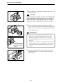
Replacing the Lamp
The lamp projects the image onto the scanner screen, and
the procedure for replacing the lamp is described below,
along with some precautions to be observed when handling
the lamp unit. If the lamp burns out, use the procedure
below to replace it.
When the lamp burns out, “LP” appears on the Error/User
Mode display.
CAUTION
Immediately after the lamp burns out, the lamp and the
metal components of the lamp unit are very hot. To
avoid being burned, allow the lamp ample time to cool
down before touching it. The lamp will cool down more
quickly if you leave the scanner switched on for some
minutes with “LP” displayed. After checking that the
lamp and the metal components have cooled down,
proceed with lamp replacement.
1 When the lamp burns out, leave the scanner switched on
for several minutes until the lamp has cooled down.
Note
After waiting at least 5 minutes, check that the lamp
has cooled down and then switch the scanner off.
2 Firmly grip the lamp unit on the right side of the main
unit and slowly pull the lamp unit out.
Note
When you remove the lamp unit, “L5” appears in the
Error/User mode display.
CAUTION
To avoid injury, do not touch the interior of the main
unit after you have removed the lamp unit.
– 39 –
Maintenance and Troubleshooting
3 Pull up the lever on the side of the lamp and remove the
burned out lamp.
CAUTION
Immediately after the lamp burns out, the lamp and the
metal components of the lamp unit are very hot. Never
handle the lamp or lamp unit while they are still hot.
handle the lamp or lamp unit while they are still hot.
4 Fit the new lamp so that the manufacturer’s mark is
facing upwards and check that the lamp is fully inserted
into the socket so that there is no gap between the lamp
and the lamp socket.
IMPORTANT
Check that there is
no gap between the
lamp and the lamp
socket.
• Use only Canon-specified lamps as replacements.
• Take care not to touch the bulb in the new lamp.
Soiling or fingermarks on the bulb can adversely
affect image quality and shorten the service life of
the bulb.
• Always check that there is no gap between the lamp
and the lamp socket. Any gap between the lamp and
the lamp socket will result in damage to the lamp
holder.
5 Push the lamp unit firmly back into place in the main
unit and check that “--” is shown on the Error/User
Mode display.
– 40 –
Maintenance and Troubleshooting
Routine Cleaning
Use the routine cleaning procedures described below to
keep the scanner components clean and ensure optimum
performance.
Cleaning the Screen and Main Unit
Use a cloth slightly dampened with water or mild detergent
to clean any soiling off the scanner screen and casing. Then
wipe the scanner with a clean dry cloth.
IMPORTANT
To avoid damaging the casing of the main unit, never
clean the unit with an organic solvent such as
thinners.
Cleaning the Lens
1 Switch off the scanner and remove the carrier and lens
unit.
2 Gently wipe off the field lens with a clean soft cloth.
3 Carefully remove the lens from the lens unit and wipe
the upper and lower surfaces of the lens with a clean dry
cloth.
– 41 –
Cleaning Mode
When the toner cartridge in the FilePrint 400 has been
replaced, the FilePrint 400 fuser roller must be cleaned.
This section describes the Cleaning mode used for fuser
roller cleaning. Refer to the FilePrint 400 Instructions for
more information on working with the FilePrint 400.
(120V model)
(220 – 240V model)
Cleaning the Fuser Roller
1 Hold down the AE key for 5 seconds to switch to
Cleaning mode. “11” or“A4” appears on the copies
display.
2 Open the multipurpose tray on the FilePrint 400 and
load a sheet of A4 paper.
3 Press the Start key. A cleaning sheet is printed and the
copies display changes to “CL”.
IMPORTANT
(Cleaning sheet)
To cancel Cleaning mode, press the Clear key before
you press the Start key. You cannot cancel Cleaning
mode once you have printed the cleaning sheet. You
must complete the fuser cleaning procedure.
4 Switch the FilePrint 400 to face-up paper eject.
5 Load the cleaning sheet in the multipurpose tray with
the printed side down and the arrow marking facing
towards the printer.
6 Press the Start key to begin fuser cleaning.
IMPORTANT
Fuser cleaning takes about 2 minutes. Do not touch
the printer during this period as no other printer
operations can be performed.
7 Once cleaning has finished, the copies display reverts to
its normal status.
– 42 –
Maintenance and Troubleshooting
Troubleshooting
If the scanner is not operating normally or not giving satisfactory results, refer to this table to
identify the cause and find the solution.
Problem
Solution
Reference Page
The screen stays
dark after I switch
the scanner on.
• Check that the lamp unit is properly fitted into the
main unit.
• Check whether the lamp has burned out. When
the lamp is burned out, “LP” appears on the
Error/User Mode display. If the lamp has burned
out, fit a new lamp.
39
The screen brightness is uneven or
the screen is too
dark.
• Check that the lens is clean.
• Check that the lens is fitted correctly.
• Check that the lamp and the lamp unit are properly fitted.
41
The image is out
of focus.
• Use the image adjustment control dial in FOCUS
mode to adjust the focus.
• Check that the carrier is installed correctly. Refer
to the instructions supplied with the carrier for
details.
• Check that the lens and the lamp are both clean.
21
The image is
skewed.
Nothing happens
when I press the
Start key.
Border removal
and automatic
skew correction
do not work correctly.
• Use the image adjustment control dial in ROTATE
mode to straighten the image.
• Check that the carrier is installed correctly. Refer
to the instructions supplied with the carrier for
details.
• If the Start key is lit red, the scanner is still warming up. Wait until the Start key turns green before
pressing it.
• If an error code is shown on the display, see “User
Call Errors” or “Service Call Errors”.
• In Scanner mode, the application software setting is
not “Semi Auto”. Check the application software
setting.
• If the image projected on the screen is similar to
the images shown on the next page, the Border
Removal function (P.27) and Automatic Skew
Correction function (P.30) will not work correctly.
Adjust the image shown on the screen.
– 43 –
39
41
22
--
Maintenance and Troubleshooting
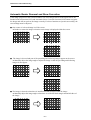
Automatic Border Removal and Skew Correction
If the image projected on the screen resembles one of the images shown in the figure below, the
Border Removal function (P.25) and Automatic Skew Correction function (P.28) cannot recognize
the image and will not process the image correctly. For these functions to operate successfully, the
screen image must be adjusted.
● One corner of a skewed image is off the screen
➜ Reduce or rotate the image so that the entire image is displayed within the screen.
or
● The image is skewed and part of the preceding and following images appear on the screen
➜ Manually adjust the image angle or adjust the image so that the preceding and following
images do not appear.
or
● The image is skewed so that there is insufficient blank margin around the image.
➜ Manually adjust the image angle so that there is sufficient blank margin around all sides of
the image.
– 44 –
Maintenance and Troubleshooting
User Call Errors
If there is a problem with the scanner, an error number indicating the specific problem appears on
the Error/User Mode display. This section gives details of the user call errors and describes how to
deal with them.
Error No.
Meaning
Solution
The lamp installed in the scanner
has burned out.
Install a new lamp unit
39
No paper in the printer
Refer to the User’s Guide for the
printer and load paper into the printer.
–
Printer is low on toner or no toner
is loaded.
Refer to the User’s Guide for the
printer and install a new toner cartridge in the printer.
–
Printer cover open.
Close the printer cover.
–
The lamp unit is not correctly
installed in the scanner.
Install the lamp unit correctly.
39
Zoom key storage failed.
Press the Clear key to cancel the error
and retry zoom key storage.
28
The paper size displayed for the
cassette or set for the multipurpose
tray does not match the paper
actually loaded.
Load the correct paper size in the
paper cassette or multipurpose tray so
that the paper size matches the paper
cassette or multipurpose tray setting.
25
• Scanner initializing immedi
ately after startup.
• Printer not switched on.
• Printer not connected.
Wait until the error disappears.
Switch the printer on.
Connect the printer or switch to
Scanner mode.
–
Paper from a paper jam is still
stuck in the printer.
Refer to the owner’s manual for the
printer and remove the jammed paper.
–
A paper jam has occurred on the
printer. One sheet of paper is
jammed.
Refer to the owner’s manual for the
printer and remove the jammed paper.
–
A paper jam has occurred on the
printer. Two sheets of paper are
jammed.
Refer to the owner’s manual for the
printer and remove the jammed paper.
A paper jam has occurred on the
printer.
Three sheets of paper are jammed.
Refer to the owner’s manual for the
printer and remove the jammed paper.
Reference Page
–
–
–
Note
The “L1”, L2", “L4”, “L8”, “L9” and “PX” user call errors are only displayed when the scanner is in ReaderPrinter mode.
– 45 –
Service Call Errors
The scanner automatically performs self-diagnostic testing each time it is switched on. If this testing
reveals a problem or if a problem arises during scanner operation, the scanner shows a service call
error on the display. A service call error is indicated by an error code consisting of an “E” followed
by three digits (“Ennn” where “n” indicates a number). This code is displayed in 2 parts as “En”
followed by “nn”. (Eg. “E123” is displayed as “E1” followed by “23”.)
When a service call error occurs, proceed as follows:
1 Immediately switch off the scanner and wait several minutes.
2 Switch the scanner on again and check the scanner status.
Note
When a service call error occurs, it is sometimes possible to resolve the problem simply by
switching the scanner off for a while and then switching it on again.
● When you cannot clear a service call error
Make a note of the error code and the nature of the problem. Then switch off the scanner and any
peripheral units such as the carrier, unplug the power cord and contact an authorized Canon service
technician.
– 46 –
Specifications
Specifications
Main Unit
Type
Screen
Scanning method
Film polarity
Lens magnification
Light source
Desktop digital microfilm scanner
300 x 435 mm transparent
300-dpi digital scanning
Negative, Positive, Negative/Positive Auto Select
7x to 7.5x, 9x to 16x, 14x to 30x, 20x to 50x, 53x, 57x
Halogen lamp with mirror (20V, 150W)
Film
Formats
Types
Base density
AE response
Microfiche, jacket, aperture card, 16/35mm roll
Silver or diazo (blue or blue-black)
0.6 to 1.4 (negative film)
0.3 or less (positive film)
0.8 to 1.2 (negative film)
0.2 or less (positive film)
Image Adjustment Functions
Focus
Zoom
Rotation
Auto, Manual
Preset zoom key, manual
Manual
Automatic rotation in 90° steps (using optional operation keyboard)
Scanning
Scan size
(ReaderPrinter mode)
(Scanner mode)
Scanning mode
(Reader Printer mode)
(Scanner mode)
Brightness adjustment
Scanning options
Other
(120V) Legal, Letter, Letter-R, Ledger and
Statement
(220–240V) A3, A4 , A4-R, B4 and B5
(120V) Legal, Letter, Letter-R, Ledger,
Statement and application specified sizes
(220–240V) A3, A4, A4-R, B4, B5 and
application specified sizes
Black and White, Black and White-Picture
*Selectable using function keys
Black and White, Black and White-ED,
Black and White-Picture, Grayscale
AE, manual
Automatic border removal, trimming
Zoom memory, user modes
General
Power supply
Operation environment
Dimensions
Weight
120V AC, 60 Hz, 4.5A
220-240V AC, 50/60Hz, 2A
Temperature: 10°C to 32.5°C (50°F to 90.5°F)
Humidity: 10% to 80% RH (no condensation)
612mm x 760mm x 600mm (H x W x D)
Approx. 47 kg
Options
Fixed-focus lenses
Zoom lenses
Carriers
Installation Kit L
Operation keyboard
128-MB additional memory
Foot switch
Framing Kit
GZ X57
GZ X7-X7.5, GZ X9-X16, GZ X14-X30, GZ X20-X50
FC 190RII, AC 100C, AC 100R, AC 100M, FS Controller I, III,
Roll/Fiche Carrier 200
For AC 100C, AC 100R, AC 100M, FS Controller I, Roll/Fiche Carrier 200
This additional memory must be installed to scan in grayscale mode.
All specifications subject to change without notice.
– 47 –
Index
Index
A
I
Adjusting the Image ..................................... 21
Automatic Border Removal and Skew
Correction .................................................... 44
Important Components and Their Functions
Carrier pad ..............................................
DIN connector .........................................
Foot switch ..............................................
Framing Kit ..............................................
Lamp unit ................................................
Lens holder .............................................
Operation keyboard ................................
Operation panel ......................................
Power switch ...........................................
Screen .....................................................
B
Brightness Adjustment ................................. 24
Automatic adjustment ............................. 24
Manual adjustment ................................. 24
C
Checking the Date and Time .......................
Cleaning Mode .............................................
Cleaning the Fuser Roller .......................
Cleaning sheet .............................................
Connecting to a Computer ...........................
Connecting the Computer ......................
Device Drivers ........................................
37
42
42
42
17
17
17
L
Lens holder ..................................................
Lenses ..........................................................
Fixed-focus Lenses .................................
Zoom Lenses ..........................................
Loading the Film ..........................................
E
11
15
15
15
20
M
Enlarging and Reducing the Image ............. 22
Microfilm Scanner 800 ................................. 11
Microfilm Scanner 800 Instructions .............. 11
F
Focusing the Image .....................................
Auto Focus ..............................................
Manual Focus .........................................
Function Key Labels ....................................
Function key labels ......................................
Function Keys ..............................................
Programming Function Keys ..................
Functions that Can Be Assigned to the
Function Key ................................................
600 DPI ...................................................
Add on ....................................................
Adjust margins ........................................
Adjust sharpness ....................................
Assign all settings ...................................
Auto Centering ........................................
Automatic skew correction .....................
Background Erase ..................................
Import margins ........................................
Import overlay .........................................
Lower screen brightness ........................
New file ...................................................
Photo mode .............................................
Raise screen brightness .........................
ReaderPrinter mode ................................
Rotate 90° left .........................................
Rotate 90° right .......................................
Scanner mode ........................................
Standby ...................................................
12
12
12
12
12
12
12
12
12
12
12
21
21
21
32
11
29
29
O
Operation Keyboard ....................................
Disabled key ...........................................
Film control knob ....................................
Image adjust control dial ........................
Image adjust mode indicators ................
Image adjust selection key .....................
Paper Select key .....................................
RESET key ..............................................
Rotate key ...............................................
Operation Modes .........................................
Reader/Printer mode ...............................
Reader/Printer/Scanner mode ................
Scanner mode ........................................
Operation Panel ...........................................
AF (Auto Focus) key ...............................
Brightness adjustment keys ....................
Brightness indicator ................................
Clear/Stop key ........................................
Control knob ...........................................
Error/User Mode display .........................
FOCUS key .............................................
Function keys ..........................................
Negative/Positive key ..............................
Paper Select/Scan Size key ....................
Preset Zoom keys ...................................
ROTATE key ............................................
30
31
30
31
31
30
32
30
32
31
31
30
30
31
30
32
30
30
32
30
– 48 –
19
19
19
19
19
19
19
19
19
10
10
10
10
18
19
18
18
18
19
18
19
18
18
18
18
19
Index
Scanning Position key .............................
Start key ..................................................
Trimming/Border key ....................................
User Mode keys ...........................................
ZOOM (enlarge/reduce) key ........................
Optional Products ........................................
128MB Additional Memory .....................
Carriers ...................................................
FilePrint 400 ............................................
Foot Switch .............................................
Framing Kit ..............................................
Installation Kit ..........................................
Lenses ....................................................
Operation Keyboard ...............................
Setting the Date and Time ...........................
Setting the Scanning Position ......................
Software Licence Agreement .......................
Specifications ...............................................
Storing a Zoom Setting ................................
Switching Off ................................................
Switching On ................................................
18
18
18
18
19
13
13
13
13
13
13
13
13
13
36
26
11
47
28
20
20
T
Trimming/Border settings .............................
Leaving a margin around the image .......
Removing the entire border ....................
Trimming .................................................
Troubleshooting ............................................
27
27
27
27
43
P
U
Power cord ................................................... 11
Power Supply .................................................. 6
Preparing the Carrier ................................... 14
Auto Carrier 100C ................................... 14
Auto Carrier 100M ................................... 14
Auto Carrier 100R ................................... 14
Fiche Carrier 190R II ............................... 14
FS Controller I ......................................... 14
FS Controller III ....................................... 14
Roll/Fiche Carrier 200 ............................. 14
Preparing the Printer .................................... 16
User Call Errors ............................................ 45
W
Warranty Card .............................................. 11
R
Replacing the Lamp .....................................
Rotating the Image .......................................
90° Rotation ............................................
Rotation by any angle .............................
Routine Cleaning ..........................................
Cleaning the Lens ...................................
Cleaning the Screen and Main Unit ........
39
22
22
22
41
41
41
S
Scanning Utility 800 Setup CD-ROM ...........
Scanning Utility 800 User’s Guide ...............
Selecting the Paper for Printing ...................
Selecting paper for the multipurpose tray
Selecting the paper feed cassette ..........
Selecting the Polarity ...................................
Auto .........................................................
Negative ..................................................
Positive ....................................................
Selecting the Scan Size ...............................
Service Call Errors .......................................
Setting the Add On ......................................
Setting the Auto Clear Time .........................
Setting the Caption ......................................
11
11
25
25
25
23
23
23
23
26
46
33
38
35
– 49 –