1
GENERAL PRECAUTIONS REGARDING THE INSTALLATION
AND SERVICE FOR THE COPIER FC-22
The installation and service should be done by a qualified service technician.
1.
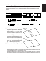
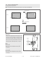
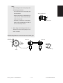
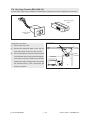
Transportation/Installation
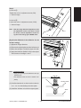
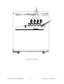
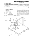
• When transporting/installing the copier, move it by the casters while lifting the stoppers.
The copier is quite heavy and weighs approximately 200 kg (441 lb), therefore pay full attention
when handling it.
• Be sure to use a dedicated outlet with AC 115V or 120V/20A (220V, 230V, 240V/10A) or more for
its power source.
• The copier must be grounded for safety.
Never ground it to a gas pipe or a water pipe.
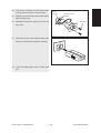
• Select a suitable place for installation.
Avoid excessive heat, high humidity, dust, vibration and direct sunlight.
• Also provide proper ventilation as the copier emits a slight amount of ozone.
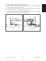
• To insure adequate working space for the copying operation, keep a minimum clearance of
80 cm (32”) on the left, 80 cm (32”) on the right and 10 cm (4”) in the rear.
2.
Service of Machines
• Basically, be sure to turn the main switch off and unplug the power cord during service.
• Be sure not to touch high-temperature sections such as the exposure lamp, the fuser unit, the
damp heater and their periphery.
• Be sure not to touch high-voltage sections such as the chargers, the transfer belt and the highvoltage transformer.
• Be sure not to touch rotating/operating sections such as gears, belts, pulleys, fan, etc.
• When servicing the machines with the main switch turned on, be sure not to touch live sections
and rotating/operating sections. Avoid exposure to laser radiation.
• Use suitable measuring instruments and tools.
• Avoid exposure to laser radiation during servicing.
− Avoid direct exposure to the beam.
− Do not insert tools, parts, etc. that are reflective into the path of the laser beam.
− Remove all watches, rings, bracelets, etc. that are reflective.
3.
Main Service Parts for Safety
• The breaker, door switch, fuse, thermostat, thermofuse, thermistor, etc. are particularly important for safety. Be sure to handle/install them properly.
4.
Cautionary Labels
• During servicing, be sure to check the rating plate and the cautionary labels such as “Unplug the
power cord during service”, “Hot area”, “Laser warning label” etc. to see if there is any dirt on
their surface and whether they are properly stuck to the copier.
5.
Disposition of Consumable Parts/Packing Materials
• Regarding the recovery and disposal of the copier, supplies, consumable parts and packing
materials, it is recommended to follow the relevant local regulations or rules.
6.
When parts are disassembled, reassembly is basically the reverse of disassembly unless
otherwise noted in this manual or other related documents. Be careful not to reassemble
small parts such as screws, washers, pins, E-rings, star washers in the wrong places.
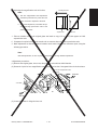
7.
Basically, the machine should not be operated with any parts removed or disassembled.
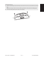
8.
Precautions Against Static Electricity
• The PC board must be stored in an anti-electrostatic bag and handled carefully using a wristband, because the ICs on it may become damaged due to static electricity.
Caution: Before using the wristband, pull out the power cord plug of the copier and make
sure that there are no uninsulated charged objects in the vicinity.
Caution
:
Dispose of used RAM-ICs (including lithium battery)
according to the manufacturer’s instructions.
Vorsicht
:
Entsorgung des gebrauchten RAM-ICs (inklusive
der Lithium-Batterie) nach Angaben des Herstellers.
1. ADJUSTMENT ITEMS
2. PREVENTIVE MAINTENANCE
(PM)
3. PRECAUTIONS FOR STORING
& HANDLING SUPPLIES
4. TROUBLESHOOTING
5. FIRMWARE UPDATING
6. WIRE HARNESS CONNECTION
DIAGRAMS
CONTENTS
1. ADJUSTMENT ITEMS ............................................................................................................... 1-1
1.1
1.2
Error Code List ....................................................................................................................... 1-1
Self Diagnostic Mode ............................................................................................................. 1-6
1.2.1
Input check (Test mode 03) ...................................................................................... 1-8
1.2.2
Output check (Test mode 03) ................................................................................... 1-15
1.2.3
Test print mode (04) .................................................................................................. 1-19
1.2.4
Adjustment mode (05) .............................................................................................. 1-20
1.2.5
Setting mode (08) ..................................................................................................... 1-33
1.2.6
Registering/changing ID codes ................................................................................. 1-43
1.3
Adjustment Order (Copy Image Related Adjustment) ............................................................ 1-45
1.4
Automatic Adjustment of the Auto-Toner Circuit ..................................................................... 1-46
1.5
Automatic Initialization of Image Quality Control ................................................................... 1-50
1.6
Copy Image Dimensional Adjustment .................................................................................... 1-51
1.6.1
Paper alignment (paper buckle) at the main registration roller ................................. 1-53
1.6.2
Feed motor speed adjustment .................................................................................. 1-54
1.6.3
Printer related adjustment ........................................................................................ 1-55
1.6.4
Scanner related adjustment ...................................................................................... 1-58
1.7
Automatic Adjustment of Gamma Correction ......................................................................... 1-66
1.8
Density Adjustment ................................................................................................................ 1-68
1.9
Color Balance Adjustment ...................................................................................................... 1-69
1.10 Offset Amount for Processing Background ............................................................................ 1-70
1.11 Judgment Threshold for ACS ................................................................................................. 1-71
1.12 AI Mode Setting ..................................................................................................................... 1-72
1.13 Sharpness Adjustment ........................................................................................................... 1-73
1.14 High-Voltage Transformer Setting .......................................................................................... 1-74
1.14.1 Overview ................................................................................................................... 1-74
1.14.2 Settings after replacing main high-voltage transformers .......................................... 1-74
1.14.3 Settings after replacing transfer transformer ............................................................ 1-75
1.15 Adjusting Doctor-to-Sleeve Gap ............................................................................................ 1-76
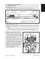
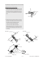
1.16 Adjusting the Scanner Section ............................................................................................... 1-77
1.16.1 Adjusting the carriage ............................................................................................... 1-77
1.16.2 Lens unit ................................................................................................................... 1-80
1.17 Adjusting the Cassette for Sidewise Deviation ...................................................................... 1-83
1.18 Key Copy Counter (MU-8, MU-10) ......................................................................................... 1-84
2. PREVENTIVE MAINTENANCE (PM) ......................................................................................... 2-1
2.1
Types of Preventive Maintenance .......................................................................................... 2-1
2.2
Maintenance to be Performed Every 30,000, 60,000, 90,000 and 120,000 Copies .............. 2-2
2.3
Preventive Maintenance Checklist ......................................................................................... 2-2
2.4
PM Kit .................................................................................................................................... 2-12
FC-22 CONTENTS
I
January 2000 © TOSHIBA TEC
2.5
List of Adjustment Tools ......................................................................................................... 2-13
3. PRECAUTIONS FOR STORING & HANDLING SUPPLIES ...................................................... 3-1
3.1
Precautions for Storing TOSHIBA Supplies ........................................................................... 3-1
3.2
Checking and Cleaning of the Photoconductive Drum .......................................................... 3-1
3.3
Checking and Cleaning of the Drum Cleaning Blade and Transfer Belt Cleaning Blade ....... 3-2
3.4
Checking and Replacing the Oil Roller and Cleaning Roller of Fuser Section ...................... 3-3
3.5
Checking and Cleaning of the Fuser Rollers ......................................................................... 3-3
3.6
Checking and Replacing the Transfer Belt ............................................................................. 3-4
3.7
Checking and Replacing the Transfer Roller .......................................................................... 3-4
4. TROUBLESHOOTING ................................................................................................................ 4-1
4.1
Troubleshooting Based on Error Code ................................................................................... 4-1
4.1.1
Paper transport jam inside the copier ....................................................................... 4-1
4.1.2
Paper feeding jam ..................................................................................................... 4-3
4.1.3
Paper transport jam (Paper not reaching the registration sensor after feeding) ....... 4-5
4.1.4
Cover open jam ........................................................................................................ 4-6
4.1.5
Paper jam in ADU and reversing area ...................................................................... 4-8
4.1.6
Original jam in the RADF .......................................................................................... 4-10
4.1.7
Paper jam in the sorter ............................................................................................. 4-12
4.1.8
Special sheet jam ..................................................................................................... 4-15
4.1.9
Drive system related service call .............................................................................. 4-16
4.1.10 Paper feeding system related service call ................................................................ 4-20
4.1.11 Scanner related service call ..................................................................................... 4-23
4.1.12 Copy process related service call ............................................................................. 4-25
4.1.13 Fuser unit related service call ................................................................................... 4-30
4.1.14 Communications related service call ........................................................................ 4-33
4.1.15 ADF related service call ............................................................................................ 4-36
4.1.16 Other service calls .................................................................................................... 4-37
4.1.17 Laser optical unit related service call ........................................................................ 4-38
4.1.18 Sorter related service call ......................................................................................... 4-40
4.1.19 Image quality related service call ............................................................................. 4-45
4.1.20 Options related service call ...................................................................................... 4-52
4.1.21 Image processing options related service call .......................................................... 4-53
4.2
Troubleshooting of Image ....................................................................................................... 4-54
5. FIRMWARE UPDATING ............................................................................................................. 5-1
5.1
[3] [9] Mode Operation ........................................................................................................... 5-1
5.1.1
Outline ...................................................................................................................... 5-1
5.1.2
Preparation of PC ..................................................................................................... 5-1
5.1.3
Firmware update operation ....................................................................................... 5-4
January 2000 © TOSHIBA TEC
II
FC-22 CONTENTS
5.1.4
5.2
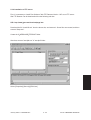
Screen details ........................................................................................................... 5-10
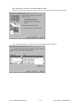
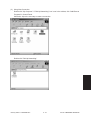
Installation Instructions for Firmware Update through PC ..................................................... 5-14
5.2.1
Outline ...................................................................................................................... 5-14
5.2.2
System configuration ................................................................................................ 5-14
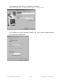
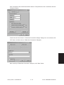
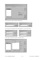
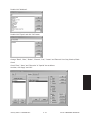
5.2.3
Preparation of PC to use a network .......................................................................... 5-15
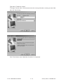
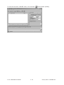
5.2.4
Installation of FTP server .......................................................................................... 5-25
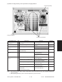
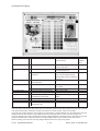
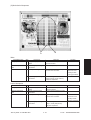
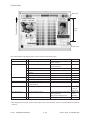
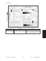
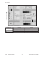
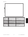
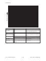
6. WIRE HARNESS CONNECTION DIAGRAMS .......................................................................... 6-1
6.1
AC Wire Harness ................................................................................................................... 6-1
6.2
DC Wire Harness .......................................................................................................... Appendix
FC-22 CONTENTS
III
January 2000 © TOSHIBA TEC
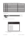
In this manual, colors are sometimes described using abbreviations as listed below:
Yellow : Y
1.
Magenta : M
Cyan : C
Black : K
ADJUSTMENT ITEMS
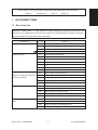
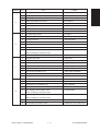
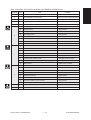
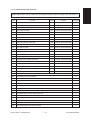
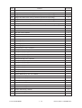
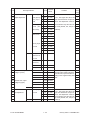
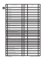
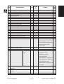
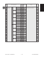
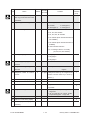
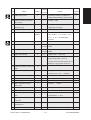
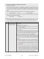
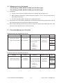
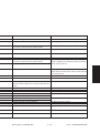
1.1 Error Code List
While the “CLEAR PAPER” or “CALL SERVICE” symbol is flashing, pressing the [CLEAR] key and
the [8] key on the digital keys at the same time shows one of the following error codes on the copyquantity indicator as long as those keys are pressed.
Classification
Error code
Paper transport jam inside the copier
E01
Paper leading edge not reaching the exit sensor
E02
Paper trailing edge not passing the exit sensor
E03
Paper remaining inside the copier at power ON
EB7
Restart time out error
E11
Paper misfeed from the ADU
E12
Paper misfeed from the bypass
E13
Paper misfeed from the 1st cassette
E14
Paper misfeed from the 2nd cassette
E15
Paper misfeed from the 3rd cassette
E16
Paper misfeed from the 4th cassette
E19
Paper misfeed from the LCF
Paper transport jam
E21
Paper transport jam from the LCF
(Paper not reaching the registration
E22
Paper transport jam from the 1st cassette
sensor after feeding)
E23
Paper transport jam from the 2nd cassette
E24
Paper transport jam from the 3rd cassette
E25
Paper transport jam from the 4th cassette
E41
Front cover opened during copying
E42
Side door opened during copying
E43
ADU unit pulled out during copying
E45
LCF jam access cover opened during copying
E46
Bypass unit opened during copying
Paper jam in ADU and reversing
E50
Paper not reaching the ADU
area
E51
Paper not restarting from the ADU stack
E52
Paper not reaching the ADU path sensor
E54
ADU paper transport jam
Paper feeding jam
Cover open jam
January 2000 © TOSHIBA TEC
Content
1-1
FC-22 ADJUSTMENT
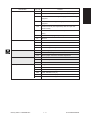
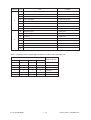
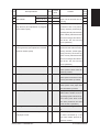
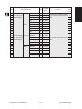
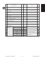
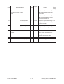
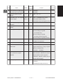
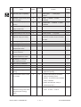
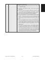
Classification
Original jam in the ADF
Error code
Content
E71
Original not reaching the aligning sensor
E72
Original not reaching the exit sensor
E73
Original not passing the exit sensor
E75
Second original not reaching the aligning sensor in 2-in-1 mode
E79
Original pre-feeding jam
EA1
Paper transport delay jam
EA2
Paper transport stop jam
EA3
Paper remaining on the sorter transport path at power on
EA4
Sorter front door opened during copying
EA5
Staple jam
EA6
Finisher/sorter early-arrival jam (P30) (internal)
EA8
Finisher saddle staple jam
EA9
Finisher saddle door open
EAA
Finisher saddle power ON jam
EAB
Finisher saddle delivery delay
EAC
Finisher saddle delivery failure
EC2
OHP sheets used except from bypass and 2nd cassette
EC3
OHP sheet used in non-OHP mode
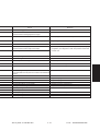
Drive system related service call
C05
ADU motor rotation abnormal
Paper feeding system related
C09
Black developer motor rotation abnormal
service call
C0A
Color developer motor rotation abnormal
C0B
Drum motor K rotation abnormal
C0C
Drum motor C rotation abnormal
C0D
Drum motor M rotation abnormal
C0E
Drum motor Y rotation abnormal
C11
ADU paper side guide function abnormal
C12
ADU paper end guide function abnormal
C13
1st cassette tray function abnormal
C14
2nd cassette tray function abnormal
C15
3rd cassette tray function abnormal
C16
4th cassette tray function abnormal
C18
LCF tray function abnormal
C27
Carriage home position sensor not turning OFF within a fixed time
C28
Carriage home position sensor not turning ON within a fixed time
C29
Exposure lamp disconnection detected
Paper jam in the sorter
Paper jam in the sorter
Special sheet jam
Scanner related service call
FC-22 ADJUSTMENT
1-2
January 2000 © TOSHIBA TEC
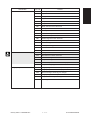
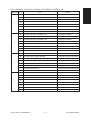
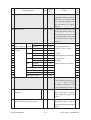
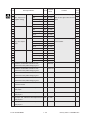
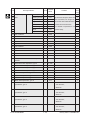
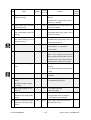
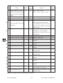
Classification
Copy process related service call
January 2000 © TOSHIBA TEC
Error code
Content
C31
Used toner transport motor rotation abnormal
C33
Developer removal shutter function abnormal
C35
Transfer belt unit contact/release function abnormal
C37
Transfer belt moter rotation abnormal
C38
Auto toner initializing error (K)
C39
Auto toner initializing error (C)
C3A
Auto toner initializing error (M)
C3B
Auto toner initializing error (Y)
C3C
Main charger wire abnormal (K)
C3D
Main charger wire abnormal (C)
C3E
Main charger wire abnormal (M)
C3F
Main charger wire abnormal (Y)
1-2-1
FC-22 ADJUSTMENT
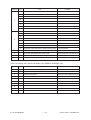
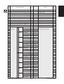
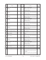
Classification
Fuser unit related service call
Error code
Content
C41
Thermistor or heater abnormal when warming-up is started
C42
Thermistor abnormal after the copier becomes ready
C43
Thermistor abnormal during warming-up after abnormality
judgment
C44
Heater abnormal during warming-up after abnormality
judgment
C46
Heater abnormal (low temperature) after the copier has
become ready
C47
Rear thermistor abnormal after the copier has become
ready
Communications related service call
ADF related service call
Other service calls
Laser optical unit related service call
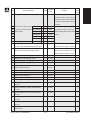
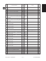
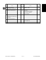
January 2000 © TOSHIBA TEC
C48
Heater abnormal (high temperature)
C7
Error C7
C57
Communications error between Main-CPU and Sorter-CPU
C5A
Communications error between Main-CPU and printer controller
C5B
Main-CPU signal transmission error to IMC-CPU
C5C
Main-CPU signal reception error from IMC-CPU
C72
Error of aligning sensor automatic adjustment
C73
EEPROM initializing error
C74
Error of paper exit sensor automatic adjustment
C94
Main-CPU abnormal
C9A
Main memory abnormal
C9E
IMC board connection abnormal
CA1
Polygonal motor rotation abnormal
CA2
H-SYNC abnormal
CD1
Laser calibration error (K)
CD2
Laser calibration error (C)
CD3
Laser calibration error (M)
CD4
Laser calibration error (Y)
1-3
FC-22 ADJUSTMENT
Classification
Sorter related service call
Sorter related service call
Image quality related service call
January 2000 © TOSHIBA TEC
Error code
Content
CB1
Delivery motor abnormal
CB2
Paper exit motor abnormal
CB3
Tray-up motor abnormal
CB4
Alignment motor abnormal
CB5
Staple motor abnormal
CB6
Staple unit shift motor abnormal
CB7
Stack detection sensor abnormal
CB8
Backup RAM data abnormal
CB9
Saddle push motor abnormal
CBA
Saddle outer staple motor abnormal
CBB
Saddle inner staple motor abnormal
CBC
Saddle alignment motor abnormal
CBD
Saddle guide motor abnormal
CBE
Saddle folding motor abnormal
CBF
Saddle positioning plate motor abnormal
CC0
Sensor connector connection abnormal
CC2
Micro-switch abnormal
CC1
Transport motor rotation abnormal
CC3
Bin shift motor rotation abnormal
CC4
Guide bar swing motor rotation abnormal
CC5
Staple-unit swing motor rotation abnormal
CCA
Automatic adjustment error of bin inside paper sensor
CCC
No power being supplied
CE1
Image quality sensor abnormal (OFF level)
CE2
Image quality sensor abnormal (no pattern level)
CE3
Abnormal image caused by poor charger
CE4
Image quality control test pattern abnormal
CE5
Temperature/humidity sensor upper-limit abnormal
CF1
Color registation control abnormal
1-3-1
FC-22 ADJUSTMENT
Classification
Options related service call
Image processing options related
service call
FC-22 ADJUSTMENT
Error code
Content
F07
Communications error between System-CPU and Main-CPU
F11
Communications error between System-CPU and Scanner-CPU
F51
Communications error between System-CPU and AI-board
during pre-scanning
1-4
January 2000 © TOSHIBA TEC
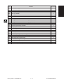
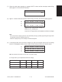
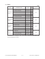
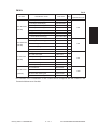
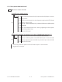
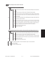
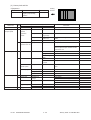
<<Error history>>
Under code 253 in the setting mode (08), the latest eight groups of error data will be displayed.
Display example
EA1
99 08 26 17 57 32
64
64
236210000000
Error code
YY MM DD HH MM SS
MMM
NNN
ABCDEFHIJLOP
3 digits
12 digits
3 digits
3 digits
12 digits
A
Paper source
0:Not fixed 1:Bypass feed 2:LCF 3:1st 4:2nd 5:3rd 6:4th 7:ADU feed
B
Paper size code
0:A5/ST 1:A5-R 2:ST-R 3:LT 4:A4 5:B5-R 6:LT-R 7:A4-R 8:OTHER/UNIV 9:B5
A:FOL/COM B:LG C:B4 D:LD E:A3 Z:Not selected
Sort mode
0:Not selected 1:Group 2:Sort 6:Staple sort
C
D
DF mode
0:Unused 1:AUTO FEED (SADF) 2:STACK FEED
E
APS/AMS mode
0:Not selected 1:APS 2:AMS
F
Duplex mode
0:Not selected 1:BOOK 2:Two-sided/Single-sided 4:Two-sided/Duplexed 8:Single-sided/Duplexed
G
H
Unused
Binding space
0:Unused 1:BOOK 2:LEFT 4:RIGHT
Editing
0:Unused 1:Masking 2:Trimming 3:Mirror image 4:Negative/Positive
I
J
K
L
MMM
Edge erase/Dual-page
0:Unused 1:Edge erase 2:Dual-page 3:Edge erase & Dual-page
Unused
Function
0:Copying 1:Unused (Extended copying) 2:Unused (Fax input) 3:Unused (Fax printing)
4:Printing 5:Unused (DSS)
Primary-scanning reproduction ratio (Display in hexadecimal)
(Mx256)+(Mx16)+M
NNN
Secondary-scanning reproduction ration (Display in hexadecimal)
(Nx256)+(Nx16)+N
O
Color mode
0:Auto color 1:Full color 2:Black 3:Monocolor
P
AI board
0:Unused 1:Used
January 2000 © TOSHIBA TEC
1-5
FC-22 ADJUSTMENT
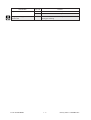
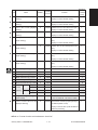
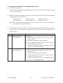
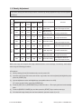
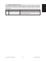
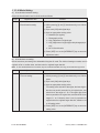
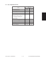
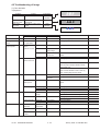
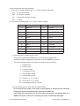
1. 2 Self Diagnostic Mode
Mode
Input method
Meaning
Clearing
Whole control panel light-
[0]+[1]+[POWER]
All control-panel LEDs are lit,
[C] or [POWER]
and all LCD pixels are turned
OFF/ON
ing mode
on/off repeatedly.
Test mode
[0]+[3]+[POWER]
Input/output signals are [POWER] OFF/ON
checked
Test print mode
[0]+[4]+[POWER]
A test pattern print is made.
[POWER] OFF/ON
Adjustment mode
[0]+[5]+[POWER]
Adjustment of various items
[POWER] OFF/ON
Setting mode
[0]+[8]+[POWER]
Setting of various items
[POWER] OFF/ON
Note: Input method for various modes:
While pressing simultaneously the two digital keys corresponding to the mode you want to set
(for example, [0] and [5]), turn on the main switch [POWER].
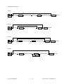
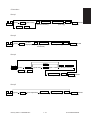
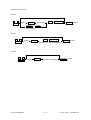
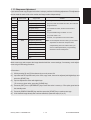
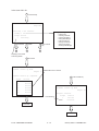
<Operation procedure>
CLEAR or POWER OFF/ON
(Exit)
0
1
Power
(All control-panel LEDs light)
START
(Check Key)
CLEAR
(Exit)
START
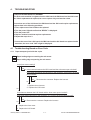
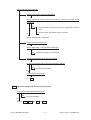
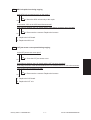
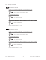
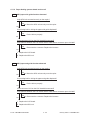
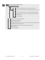
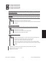
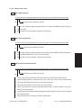
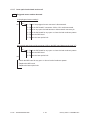
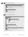
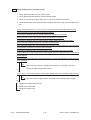
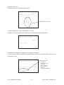
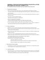
• Whole control-panel lighting mode (01) :
Notes: 1. During the “Check keys” mode, [CLEAR] alone can do.
During the “Whole control-panel lighting mode”, [CLEAR] can clear the mode.
2. Check keys : Any key with LED (when it is pressed, the LED goes out.)
Any key without LED (When it is pressed, an indication is made in the message area.)
• Test mode (03)
:Refer to Sec. 1.2.1 and 1.2.2 for test modes.
• Test print mode (04)
: Refer to Sec. 1.2.3 for test print modes.
• Adjustment mode (05) : Refer to Sec. 1.2.4 for adjustment modes.
• Setting mode (08)
FC-22 ADJUSTMENT
: Refer to Sec. 1.2.5 for setting modes.
1-6
January 2000 © TOSHIBA TEC
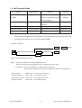
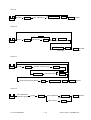
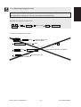
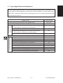
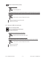
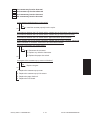
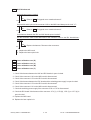
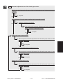
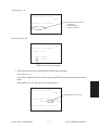
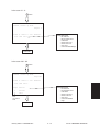
[Power] ON
Normal
[0][1]
[0][3]
*1
[0][5]
[0][8]
[0][4]
[CLEAR]
All the displays on
the control panel lit
Warming up
Test mode
Adjustment mode Setting mode
Test print mode
Standby
[Power] OFF/ON
*2
Hand over to user
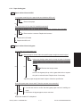
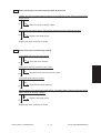
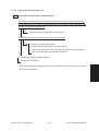
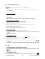
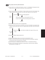
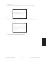
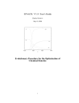
Transition diagram of self-diagnostic mode conditions
*1 : During the “Whole control-panel lighting mode”, copying is not possible. But after pressing [CLEAR]
to make the copier ready, you can make copies.
*2 : After having used the self-diagnostic mode, be sure to turn OFF and then ON the power before
returning the copier to the customer.
January 2000 © TOSHIBA TEC
1-7
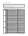
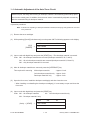
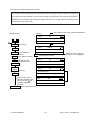
FC-22 ADJUSTMENT
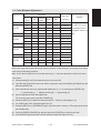
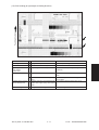
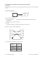
1. 2. 1 Input check (Test mode 03)
The status of each item can be checked by setting ON/OFF of each [FULL COLOR], [AUTO COLOR],
[ENERGY SAVER], and then pressing each of the corresponding digital key in this test mode 03.
Note: When icon is displayed with black letter on white background, it indicates the value is 0, while
in reverse black and white, it indicates the value is 1.
[FULL COLOR]key: OFF, [AUTO COLOR]key: OFF, [ENERGY SAVER]key: OFF
Digital key
1
2
3
4
Icon
Item
Condition
A
Paper size switch 0 (1st cassette : Lower)
0: Switch is ON
B
Paper size switch 1 (1st cassette : Middle lower)
0: Switch is ON
C
Paper size switch 2 (1st cassette : Middle upper)
0: Switch is ON
D
Paper size switch 3 (1st cassette : Upper)
0: Switch is ON
E
Cassette paper empty sensor (1st cassette)
1: No paper
F
Cassette tray-up limit sensor (1st cassette)
1: Tray is upper limit
G
Cassette-feed jam sensor (1st cassette)
1: Paper exist
H
—
A
Paper size switch 0 (2nd cassette : Lower)
0: Switch is ON
B
Paper size switch 1 (2nd cassette : Middle lower)
0: Switch is ON
C
Paper size switch 2 (2nd cassette : Middle upper)
0: Switch is ON
D
Paper size switch 3 (2nd cassette : Upper)
0: Switch is ON
E
Cassette paper empty sensor (2nd cassette)
1: No paper
F
Cassette tray-up limit sensor (2nd cassette)
1: Tray is upper limit
G
Cassette-feed jam sensor (2nd cassette)
1: Paper exist
H
—
A
Paper size switch 0 (3rd cassette : Lower)
0: Switch is ON
B
Paper size switch 1 (3rd cassette : Middle lower)
0: Switch is ON
C
Paper size switch 2 (3rd cassette : Middle upper)
0: Switch is ON
D
Paper size switch 3 (3rd cassette : Upper)
0: Switch is ON
E
Cassette paper empty sensor (3rd cassette)
1: No paper
F
Cassette tray-up limit sensor (3rd cassette)
1: Tray is upper limit
G
Cassette-feed jam sensor (3rd cassette)
1: Paper exist
H
—
A
Paper size switch 0 (4th cassette : Lower)
0: Switch is ON
B
Paper size switch 1 (4th cassette : Middle lower)
0: Switch is ON
C
Paper size switch 2 (4th cassette : Middle upper)
0: Switch is ON
D
Paper size switch 3 (4th cassette : Upper)
0: Switch is ON
E
Cassette paper empty sensor (4th cassette)
1: No paper
F
Cassette tray-up limit sensor (4th cassette)
1: Tray is upper limit
G
Cassette-feed jam sensor (4th cassette)
1: Paper exists
H
—
FC-22 ADJUSTMENT
1-8
January 2000 © TOSHIBA TEC
Digital key
5
6
Icon
Item
Condition
A
Bypass paper-width sensor 0
Refer to Table 1.
B
Bypass paper-width sensor 1
Refer to Table 1.
C
Bypass paper-width sensor 2
Refer to Table 1.
D
Bypass paper-width size sensor 3
Refer to Table 1.
E
Bypass paper sensor
1: No paper
F
Bypass unit open/close switch
1: Unit is open
G
Side door open/close switch
1: Side door is open
H
Bypass unit is installed or not
0: Unit is installed
A
LCF paper empty sensor
1: No paper
B
LCF lower-limit sensor
1: Tray limit (lower)
C
LCF tray-up sensor
1: Tray limit (upper)
D
LCF tray-down switch
0: Switch is ON
E
LCF paper supply door switch
1: Door is open
F
LCF is installed or not
0: LCF is installed
G
ADU motor rotation status
0: Normal rotation
(Motor is rotating by 03 Output mode)
7
H
ADU unit is installed or not
0: ADU unit is installed
A
ADU paper jam switch
1: Paper exist
B
ADU paper empty switch
0: No paper
C
ADU end switch
1: End guide is positioned at home position
D
ADU side switch
1: Side guide is positioned at home position
E
—
F
Total counter is installed or not
0: Total counter is installed
G
Key copy counter is installed or not
0: Key copy counter is installed
H
—
A
Developer removal shutter home position sensor
B
—
C
Transfer belt unit is installed or not
D
—
E
Color developer motor rotation status
8
0: Shatter is closed
0: Unit is installed
0: Normal rotation
(Motor is rotating by 03 Output mode)
F
Black developer motor rotation status
0: Normal rotation
(Motor is rotating by 03 Output mode)
G
Transfer belt limit switch
0: Transfer belt is black mode position
H
Transfer belt home position switch
0: Transfer belt is color mode position
January 2000 © TOSHIBA TEC
1-9
FC-22 ADJUSTMENT
Digital key
9
0
Icon
Item
Condition
A
External printer controller power ON/OFF
0: Controller power ON
B
—
C
—
D
Front-cover switch
1: Front cover is open
E
OHP center sensor
0: Opaque paper is installed
F
—
G
Registration sensor
1: Paper exist
H
IPC-IF board (Sorter installation kit) is installed or not
0: Board installed
A
ADU path sensor
1: Paper exist
B
—
C
Exit sensor
1: Paper exist
D
Paper-exit unit open/close switch
1: Paper-exit unit is open
E
Toner bag limit sensor
1: Used toner full
F
—
G
—
H
—
Table 1. Relation between bypass paper-width sensor status and paper width size.
Bypass paper-width sensor
Paper-width size
3
2
1
0
0
1
1
1
A3/LD
1
0
1
1
A4-R/LT-R
1
1
0
1
A5-R/ST-R
1
1
1
0
Card size
0
0
1
1
B4-R/LG
1
0
0
1
B5-R
FC-22 ADJUSTMENT
1 - 10
January 2000 © TOSHIBA TEC
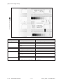
[FULL COLOR]key: OFF, [AUTO COLOR]key: OFF, [ENERGY SAVER]key: ON
Digital key
1
2
3
4
Icon
Item
Condition
A
—
B
—
C
—
D
—
E
—
F
—
G
—
H
—
A
Developer cartridge Y is installed or not
0: Cartirdge is installed
B
Developer cartridge M is installed or not
0: Cartirdge is installed
C
Developer cartridge C is installed or not
0: Cartirdge is installed
D
Developer cartridge K is installed or not
0: Cartirdge is installed
E
Processing unit is installed or not
0: Unit is installed
F
Fuser unit is installed or not
0: Unit is installed
G
—
H
—
A
Wire cleaner home position switch Y
0: Cleaning pad is positioned at home position.
B
Wire cleaner home position switch M
0: Cleaning pad is positioned at home position.
C
Wire cleaner home position switch C
0: Cleaning pad is positioned at home position.
D
Wire cleaner home position switch K
0: Cleaning pad is positioned at home position.
E
Wire cleaner limit switch Y
0: Cleaning pad is positioned at limit position.
F
Wire cleaner limit switch M
0: Cleaning pad is positioned at limit position.
G
Wire cleaner limit switch C
0: Cleaning pad is positioned at limit position.
H
Wire cleaner limit switch K
0: Cleaning pad is positioned at limit position.
A
—
B
—
C
—
D
—
E
—
F
—
G
—
H
—
January 2000 © TOSHIBA TEC
1 - 11
FC-22 ADJUSTMENT
Digital key
Icon
Item
Condition
A
—
B
—
C
—
D
—
E
—
F
—
G
—
H
—
A
—
B
—
C
—
D
—
E
—
F
—
G
Front cover, paper-exit unit open/close check
1: Cover/unit open
H
Polygonal motor rotation status (Motor is rotating by 03 Output mode)
0: Normal rotation
7
—
—
8
—
Upper fuser roller thermistor (center) check
Thermistor output value is displayed with 8 bit.
9
—
Upper fuser roller thermistor (rear) check
Thermistor output value is displayed with 8 bit.
0
—
Lower fuser roller thermistor (center) check
Thermistor output value is displayed with 8 bit.
5
6
[FULL COLOR]key: OFF, [AUTO COLOR]key: ON, [ENERGY SAVER]key: OFF
Digital key
Icon
Item
1
—
Lower fuser roller thermistor (rear) check
Thermistor output value is displayed with 8 bit.
2
—
Temperature sensor check
Sensor output value is displayed with 8 bit.
3
—
Humidity sensor check
Sensor output value is displayed with 8 bit.
4
—
Drum thermistor Y check
Thermistor output value is displayed with 8 bit.
5
—
Drum thermistor M check
Thermistor output value is displayed with 8 bit.
6
—
Drum thermistor C check
Thermistor output value is displayed with 8 bit.
7
—
Drum thermistor K check
Thermistor output value is displayed with 8 bit.
8
—
—
9
—
—
0
—
—
FC-22 ADJUSTMENT
Condition
1 - 12
January 2000 © TOSHIBA TEC
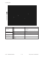
[FULL COLOR]key: OFF, [AUTO COLOR]key: ON, [ENERGY SAVER]key: ON
Digital key
Icon
1
—
—
2
—
Color registration sensor (front)
Sensor output value is displayed with 8 bit.
3
—
Color registration sensor (rear)
Sensor output value is displayed with 8 bit.
4
—
Image quality sensor
Sensor output value is displayed with 10 bit.
5
—
—
A
ADF aligning sensor
1: Original exist
B
ADF exit sensor
1: Original exist
C
ADF open/close sensor
1: ADF is open
D
ADF empty sensor
1: Original exist
E
ADF size sensor 1
F
—
G
ADF size sensor 2
H
ADF unit is installed or not
A
—
B
Direct control-panel connection detection
C
Connection
D
Installation
E
—
F
Carriage home position sensor
G
Direct control-panel SW-F key (during debugging)
H
Platen sensor
A
—
B
—
C
—
D
APS sensor (APS-R)
1: Original exist
E
APS sensor (APS-C)
1: Original exist
F
APS sensor (APS-3)
1: Original exist
G
APS sensor (APS-2) (for A4 series)
1: Original exist
H
APS sensor (APS-1)
1: Original exist
9
—
Scanner SCM board input 24V check
Output value is displayed with 8 bit.
0
—
Thermistor check
—
6
7
8
Item
January 2000 © TOSHIBA TEC
Condition
1: ADF unit is installed
1: Carriage is home position
1: Platen cover is closed
1 - 13
FC-22 ADJUSTMENT
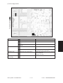
[FULL COLOR]key: ON, [AUTO COLOR]key: OFF, [ENERGY SAVER]key: OFF
Digital key
Icon
Item
Condition
1
—
Auto-toner sensor Y
Sensor output value is displayed with 8 bit.
2
—
Auto-toner sensor M
Sensor output value is displayed with 8 bit.
3
—
Auto-toner sensor C
Sensor output value is displayed with 8 bit.
4
—
Auto-toner sensor K
Sensor output value is displayed with 8 bit.
5
—
—
6
—
—
7
—
—
8
—
—
9
—
—
0
—
—
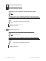
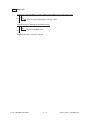
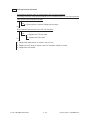
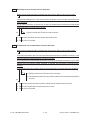
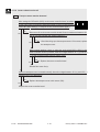
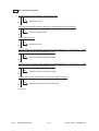
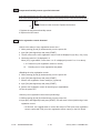
<Operation procedure>
0
3
POWER
START
( FULL COLOR AUTO COLOR ENERGY SAVER
Digital keys )
(LCD ON)
POWER OFF/ON
(Exit)
Note:
After initialization, the copier goes into the test mode.
Note: When icon is displayed with white letter on black background on the control panel,
it indicates the value is 1.
FC-22 ADJUSTMENT
1 - 14
January 2000 © TOSHIBA TEC
1. 2. 2 Output check (Test mode 03)
Output signal status can be checked by inputting the following code according to this test mode 03.
Code
Function
Code
Function
Procedure
150
All output OFF
1
101
Drum motor and transfer belt motor rotation with normal running speed ON
151
Code No. 101 function OFF
1
102
Drum motor and transfer belt motor rotation with OHP copying speed (low) ON
152
Code No. 102 function OFF
1
103
Paper feed motor ON
153
Code No. 103 function OFF
1
104
Fuser motor ON
154
Code No. 104 function OFF
1
105
Color developer motor ON
155
Code No. 105 function OFF
1
106
Black developer motor ON
156
Code No. 106 function OFF
1
107
Registration clutch ON
157
Code No. 107 function OFF
1
108
Used-toner transport motor ON
158
Code No. 108 function OFF
1
109
ADU motor ON
159
Code No. 109 function OFF
1
110
Toner motor (Y) ON
160
Code No. 110 function OFF
1
111
Toner motor (M) ON
161
Code No. 111 function OFF
1
112
Toner motor (C) ON
162
Code No. 112 function OFF
1
113
Toner motor (K) ON
163
Code No. 113 function OFF
1
114
Image quality sensor shutter solenoid ON
164
Code No. 114 function OFF
1
130
Polygonal motor standby speed ON
180
Code No. 130 function OFF
1
131
Polygonal motor normal speed ON
181
Code No. 131 function OFF
1
132
Image quality sensor LED ON
182
Code No. 132 function OFF
1
133
Color registration sensor LED (front) ON
183
Code No. 133 function OFF
1
134
Color registration sensor LED (rear) ON
184
Code No. 134 function OFF
1
135
Image quality sensor mode switching ON (Black mode)
185
Code No. 135 function OFF (Color mode)
1
201
1st cassette feed clutch ON/OFF
3
202
2nd cassette feed clutch ON/OFF
3
203
3rd cassette feed clutch ON/OFF
3
204
4th cassette feed clutch ON/OFF
3
205
Feed path clutch ON/OFF
2
206
Bypass feed clutch ON/OFF
3
207
1st cassette tray-up motor ON (tray goes up)
2
208
2nd cassette tray-up motor ON (tray goes up)
2
209
3rd cassette tray-up motor ON (tray goes up)
2
210
4th cassette tray-up motor ON (tray goes up)
2
211
Paper-exit gate solenoid ON/OFF
3
212
Total counter count up
2
213
Ozone exhaust fan motor ON/OFF
3
214
Fuser exhaust fan motor speed Low/High
3
January 2000 © TOSHIBA TEC
1 - 15
FC-22 ADJUSTMENT
Code
Function
Procedure
215
SIC fan motor speed Low/High
3
216
Charger wire cleaner drive motor (Y) CW/CCW (continuous reciprocating)
2
217
Charger wire cleaner drive motor (M) CW/CCW (continuous reciprocating)
2
218
Charger wire cleaner drive motor (C) CW/CCW (continuous reciprocating)
2
219
Charger wire cleaner drive motor (K) CW/CCW (continuous reciprocating)
2
220
Transfer-belt contact/release motor CW/CCW (continuous reciprocating)
2
221
Developer removal shutter open/close motor CW/CCW (continuous reciprocating)
2
223
LCF paper-feed motor ON/OFF
3
224
LCF tray motor ON/OFF
2
225
ADU feed clutch ON/OFF
3
226
ADU gate solenoid ON/OFF
3
227
ADU side motor ON/OFF
3
228
ADU end motor ON/OFF
3
235
Main charger (Y) ON/OFF
3
236
Main charger (M) ON/OFF
3
237
Main charger (C) ON/OFF
3
238
Main charger (K) ON/OFF
3
239
Developer bias (Y) DC (+) ON/OFF
3
240
Developer bias (M) DC (+) ON/OFF
3
241
Developer bias (C) DC (+) ON/OFF
3
242
Developer bias (K) DC (+) ON/OFF
3
243
Developer bias (Y) DC (–) ON/OFF
3
244
Developer bias (M) DC (–) ON/OFF
3
245
Developer bias (C) DC (–) ON/OFF
3
246
Developer bias (K) DC (–) ON/OFF
3
247
Developer bias (Y) AC ON/OFF
3
248
Developer bias (M) AC ON/OFF
3
249
Developer bias (C) AC ON/OFF
3
250
Developer bias (K) AC ON/OFF
3
251
Cleaning blade bias (Y) AC + DC ON/OFF
3
252
Cleaning blade bias (M) AC + DC ON/OFF
3
253
Cleaning blade bias (C) AC + DC ON/OFF
3
254
Cleaning blade bias (K) AC + DC ON/OFF
3
255
Transfer roller bias (Y) ON/OFF
3
256
Transfer roller bias (M) ON/OFF
3
257
Transfer roller bias (C) ON/OFF
3
258
Transfer roller bias (K) ON/OFF
3
259
Paper suction charger ON/OFF
3
260
Discharge LED (Y) ON/OFF
3
FC-22 ADJUSTMENT
1 - 16
January 2000 © TOSHIBA TEC
Code
Function
Procedure
261
Discharge LED (M) ON/OFF
3
262
Discharge LED (C) ON/OFF
3
263
Discharge LED (K) ON/OFF
3
280
Laser (Y) ON/OFF
3
281
Laser (M) ON/OFF
3
282
Laser (C) ON/OFF
3
283
Laser (K) ON/OFF
3
300
Carriage fan motor rotation when standby (low speed) ON/OFF
3
301
Carriage fan motor rotation when running (high speed) ON/OFF
3
302
SCM fan motor rotation speed Low/High
3
304
Scanner exposure lamp ON/OFF
4
331
ADF pick-up roller rotation ON/OFF
3
332
ADF aligning roller rotation ON/OFF
3
333
ADF transport-belt CW rotation ON/OFF
3
334
ADF transport-belt CCW rotation ON/OFF
3
351
Scan motor (carriage 1 reciprocating)
3
352
Document motor (indicator 1 reciprocating)
3
353
ADF single-sided original feeding
3
354
ADF two-sided original feeding
3
355
ADF original exiting
3
356
ADF 2 in 1 original feeding
3
January 2000 © TOSHIBA TEC
1 - 17
FC-22 ADJUSTMENT
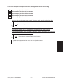
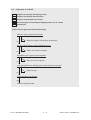
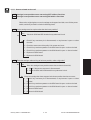
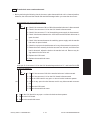
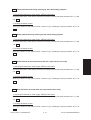
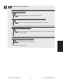
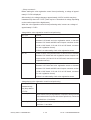
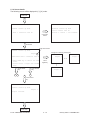
<Operation procedure>
Group 1
0
3
POWER
(Code)
START
(Code)
START
(Operation ON)
START
(Code)
POWER OFF/ON
(Exit)
(Operation OFF)
Group 2
0
3
POWER
CLEAR
(One-direction operation)
POWER OFF/ON
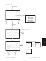
(Exit)
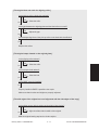
Group 3
0
3
POWER
(Code)
START
(Operation ON)
START
(Operation OFF)
CLEAR
POWER OFF/ON
(Exit)
Group 4
0
3
POWER
(Code)
START
(Operation ON)
START
or CLEAR
(Operation OFF)
POWER OFF/ON
(Exit)
6 sec. later
FC-22 ADJUSTMENT
1 - 18
January 2000 © TOSHIBA TEC
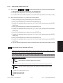
1. 2. 3 Test print mode (04)
In the 04 test print mode, you can print the test patterns matching with each item if you input the
following codes.
Code
Types of test pattern
Remarks
Paper size
11
2-pixel modulation pattern for creating γ table
A3
12
3-pixel modulation pattern for creating γ table
A3
13
1-pixel modulation pattern for checking γ table
A3
14
2-pixel modulation pattern for checking γ table
A3
15
3-pixel modulation pattern for checking γ table
A3
24
Gray 2-pixel modulation pattern for checking γ table
A3
25
Gray 3-pixel modulation pattern for checking γ table
A3
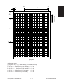
204
Grid pattern (Printer reproduction ratio/Registration
Pattern width: 1 dot, Pitch: 5mm
adjustment pattern)
(same as the adjustment pattern
A3/LD
by [05] mode [1][SETTINGS])
219
6% test pattern
220
8% test pattern
230
Gradation check pattern (2 Pixels standard)
None
Pattern width: 10mm,
A3/LD
32 gradation steps
231
Gradation check pattern (3 Pixels standard)
Pattern width: 10mm,
A3/LD
32 gradation steps
234
Half tone
A3/LD
256
Density check pattern
A3/LD
291
2-pixel modulation pattern 1 for selecting pulse width
A3
292
2-pixel modulation pattern 2 for selecting pulse width
A3
Note: Full color (YMCK) mode is not available in 230, 231 and 234.
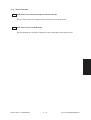
<Operation procedure>
0
4
POWER
(Code)
START
(Test print operation)
STOP
POWER OFF/ON
(Exit)
Note: 1. When an error has occurred, it is indicated, but the recovery operation is not performed. So, turn the
power OFF and then back ON to clear the error.
2. During test printing, when "Wait adding toner" is displayed, the [STOP] key is disabled.
January 2000 © TOSHIBA TEC
1 - 19
FC-22 ADJUSTMENT
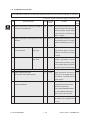
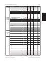
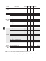
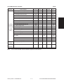
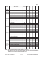
1. 2. 4 Adjustment mode (05)
In the adjustment mode 05, the following adjustment items can be corrected, changed, or checked.
Code
Description/Mode
104 Scanner (secondary scanning) copy length re-
*In code No. column, number after hyphen means sub-code.
Operation
Acceptable
Contents
Default
procedure
Value
group
128
1~255
production ratio adjustment.
When the value increases by 1, the
1
reproduction ratio in the secondary
scanning direction (vertical paper
feeding direction) increases by
approx. 0.1522%.
105 Scanner (secondary scanning) start position
128
85~171 When the value increases by 1, the
1
image shifts by approx. 0.1213mm
deviation
toward the trailing edge of the paper.
106 CCD primary scanning start For regular
position deviation
180
5~251
copy mode
When the value increases by 1, the
1
image shifts by approx. 0.042mm
toward the front side of the paper
(machine).
108
For whole-area
133
5~251
copy mode
When you input a value, which is
1
47steps (equivalent to2mm)
smaller than the set value of [106],
the rear original edge and thefront
copy edge match (0.042mm/step).
135 RADF original stop position (single-sided)
8
0~15
Changes the position where the
1
136 RADF original stop position
8
0~15
original stops.When the value in-
1
(reverse side of two-sided original)
creases by 1, the original stop position shifts by 1 mm away from the
original stopper.
137 RADF sensor automatic adjustment and
–
–
EPROM Initialization
By pressing the START key, WAIT
6
is displayed while the automatic
adjustment is performed.
Perform RADF EPROM Initialization when EPROM, RADF logic
PWA or sensors are replaced.
142 RADF 2-in-1 gap adjustment
8
0~15
When the value increases by 1, the
1
gap between two originals extend
by 1 mm.
FC-22 ADJUSTMENT
1 - 20
January 2000 © TOSHIBA TEC
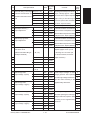
Code
Description/Mode
200 Automatic filling of developer All (Y, M, C, K)
201 material and automatic ad- Y
202 justment of the auto-toner cir- M
203 cuit
204
C
K
221
Color (Y, M, C)
213 Auto toner output value
Default
Acceptable
Value
Contents
Operation
procedure
group
–
0~255
After filling the developer from the de-
5
0~255
veloper cartridge (approx. 2.5min.),
5
0~255
auto-toner sensor output is adjusted
5
0~255
(approx. 2min.) to set in the range of
5
0~255
4.00-4.33V. (As the value increases,
5
–
0~255
the sensor output increases.)
5
0
0~1023 Auto toner output value is displayed.
10
–
–
–
–
223 Developer bias DC (–)
Y
130
0~255
As the value increases, the transformer
1
224 output adjustment
M
130
0~255
output increases. The adjustment value
1
225
C
130
0~255
becomes effective only when the setting
1
226
K
125
0~255
mode (08-400, 401, 409) is 0 (disabled).
1
241 Main charger grid bias
Y
120
0~255
As the value increases, the transformer
1
242 output adjustment
M
120
0~255
output increases. The adjustment value
1
243
C
120
0~255
becomes effective only when the setting
1
244
K
116
0~255
mode (08-400, 401, 409) is 0 (disabled).
1
–
0~255
Auto-toner sensor output is
5
245 Automatic adjustment of the All
auto-toner circuit
(Without automatic filling of
adjusted (approx. 2 min.) to set
in the range of 4.00~4.33V. (As
(C, M, Y, K)
developer material)
the value increases, the sensor
246
Y
–
0~255
247
M
–
0~255
248
C
–
0~255
249
K
–
0~255
250
Color
–
0~255
output increases.)
(Y, M, C)
252-0 Main charger bias
Y
250
0~999
Actual output voltage of main
4
252-1 output voltage 1 (lower)
M
250
0~999
charger grid bias. After replacing
4
252-2
C
250
0~999
the main high-voltage transformer,
4
252-3
K
250
0~999
input the value according to the
4
253-0 Main charger bias
Y
900
0~999
supplementary data sheet.
4
253-1 output voltage 2 (upper)
M
900
0~999
4
253-2
C
900
0~999
4
253-3
K
900
0~999
4
257-0 Developer bias DC (–)
Y
100
0~999
Actual output voltage of developer
4
257-1 output voltage 1 (lower)
M
100
0~999
bias. After replacing the main high-
4
257-2
C
100
0~999
voltage transformer, input the value
4
257-3
K
100
0~999
according to the supplementary
4
258-0 Developer bias DC (–)
Y
700
0~999
data sheet.
4
258-1 output voltage 2 (upper)
M
700
0~999
4
258-2
C
700
0~999
4
258-3
K
700
0~999
4
January 2000 © TOSHIBA TEC
1 - 21
FC-22 ADJUSTMENT
Default
Acceptable
Value
Contents
Operation
procedure
group
Full color Normal paper Y
67
0~255
The bias value of the transfer roller
1
319 output adjustment
mode (Top face)/ M
67
0~255
is set. The higher the value, the
1
320
thick paper 1 C
72
0~255
larger the transformer output be-
1
321
mode
K
67
0~255
comes. The adjustment value be-
1
326
Normal paper Y
67
0~255
comes effective only when the set-
1
327
mode (Re- M
67
0~255
ting mode (08-400, 401, 409) is 0
1
328
verse face)
C
72
0~255
(disabled).
1
K
67
0~255
1
Y
61
0~255
1
331
M
101
0~255
1
332
C
111
0~255
1
333
K
141
0~255
1
334
Thick paper Y
67
0~255
1
335
2 mode
M
67
0~255
1
336
C
72
0~255
1
337
K
67
0~255
1
Normal paper mode K
56
0~255
1
56
0~255
1
Code
Description/Mode
318 Transfer bias
329
330
361
OHP mode
Black
(Top face)/Thick paper 1 mode
Normal paper mode K
363
(Reverse face)
364
OHP mode
K
82
0~255
1
365
Thick paper2 mode K
56
0~255
1
367-0 Transfer bias output
Y
589
4
367-1 voltage 1 (lower)
M
589
367-2
C
589
367-3
K
589
0~5000 Actual output voltage of transfer
roller bias. After replacing the trans0~5000
fer transformer, input the value ac0~5000 cording to the supplementary data
0~5000 sheet.
368-0 Transfer bias output
Y
3929
0~5000
4
368-1 voltage 2 (upper)
M
3929
0~5000
4
368-2
C
3929
0~5000
4
368-3
K
4715
0~5000
4
381 Transfer bias out- Full color Thick paper Y
72
0~255
382 put adjustment
M
72
0~255
383
C
72
0~255
384
K
72
0~255
Thick paper3 mode K
72
0~255
385
FC-22 ADJUSTMENT
3 mode
Black
1 - 22
The bias value of the transfer roller
is set. The higher the value, the
larger the transformer output becomes. The adjustment value becomes effective only when the setting mode (08-400, 401, 409) is 0
(disabled).
4
4
4
1
1
1
1
1
January 2000 © TOSHIBA TEC
Default
Acceptable
Value
Contents
Operation
procedure
group
390 Automatic removing of devel- All (Y, M, C, K)
–
–
The developer material in the de-
6
391 oper material
Color (Y, M, C)
–
–
veloper unit is removed into the
6
392
K
–
–
toner bag.
6
Code
Description/Mode
400 Reproduction ratio adjustment of primary scan- 1222 1209~1235 When the value increases by 1, the
ning direction (Fine adjustment of polygonal
reproduction ratio in the primary
motor rotation speed)
scanning direction (horizontal pa-
1
per feeding direction) decreases by
approx. 0.082%. (If the values of this
code 400 is changed, the values of
code 05-401, 402, 403, 404 and
474 are optimized.)
401 Reproduction ratio adjustment of secondary 1355 1327~1382 When the value increases by 1, the
scanning direction (Fine adjustment of transfer
reproduction ratio in the secondary
belt motor rotation speed)
scanning direction (vertical paper
1
feeding direction) decreases by
approx. 0.074%. (If the values of this
code 401 is changed, the values of
code 05-401, 402, 403, 404 and
474 are optimized.)
402 Fine adjustment of fuser motor rotation speed
3794 0~65535 When the value increases by 1, the
1
rotation speed of fuser motor decreases by 0.026%.
403 Fine adjustment of drum motor rotation speed 1700 0~65535 When the value increases by 1, the
1
rotation speed of the drum motors
(Y,M,C,K) decreases by 0.059%.
404 Fine adjustment of feed motor rotation speed
4289 0~65535 When the value increases by 1, the
1
rotation speed of the paper feed
motor decreases by 0.023%.
406 Feed motor speed adjustment
–
–
The paper transport speed of reg-
6
istration roller in relation to the image printing speed is set at the optimum value. (If the value of this
code 406 is performed, the value
of code 05-404 is optimized.)
407 Color registration control forced performing
–
–
Performs the color registration con-
6
trol.
408 Correction of fuser motor rotation speed in the
0
thick paper 3 mode
0~20
In this thick paper 3 mode, when
1
the value is increased by 1, the
fuser motor rotation speed is decreased by 0.026%.
January 2000 © TOSHIBA TEC
1 - 23
FC-22 ADJUSTMENT
Code
Description/Mode
427 Right margin
Default
Acceptable
Value
Contents
Operation
procedure
group
160
0~255
Printed page right edge void (mar-
1
gin) adjustment. When the value increases by 1, the void in the right
side of paper feed direction (rear
side) decreases by approx.
0.042mm.
428 Bottom margin
160
0~255
Printed page trailing edge void
1
(margin) adjustment. When the
value increases by 1mm, the void
in the trailing edge of paper feed
direction decreases by approx.
0.042mm.
439 Paper alignment 1st
Long size
25
0~40
When the value increases by 1,
1
440 (paper buckle) at cassette Short size
25
0~40
the aligning (paper buckle)
1
441 the main registra- 2nd
Long size
25
0~40
increases by approx. 0.8mm.
1
442 tion roller
cassette Short size
25
0~40
443
3rd
Long size
25
0~40
444
cassette Short size
25
0~40
Paper length 330 mm and longer
1
445
4th
Long size
25
0~40
(A3/LD/A3 wide)
1
446
cassette Short size
25
0~40
Short size:
1
447
ADU
Long size
25
0~40
Paper length 220 mm to 329 mm
1
Short size
25
0~40
1
448
1
*Long size:
1
449
LCF
18
0~40
1
450
Bypass feed
35
0~40
1
451
Thick paper 2 mode
35
0~50
1
452
Thick paper 3 mode
35
0~50
1
0
0~255
461 Color registration status display
The value of Y (0) shows the status
10
of color registration sensor error. 0
or
16
or
above:
Normal
1-14: Data abnormal (sensor normal)
15: Color registration pattern reading error
470 Primary-scanning data write start position K
100
0~255
adjustment
When the value increases by 1, the
1
image shifts by approx. 0.042mm
toward the right side of paper feed
direction.
474 Secondary-scanning data write start position ad-
8
justment (Printer and Test print mode)
1~15
When the value increases by 1, the
1
image shifts by approx. 0.6mm toward the leading edge of paper feed
direction.
FC-22 ADJUSTMENT
1 - 24
January 2000 © TOSHIBA TEC
Code
Description/Mode
Default
482 Primary-scanning reproduction ratio (scanner)
127
Acceptable
Value
Contents
112~142 When the value increases by 1, the
Operation
procedure
group
1
reproduction ratio of the primary
scanning direction (paper feeding
in horizontal direction) decreases
by 0.082%.
Y
6
0~15
When the value increases by 1, the
1
485 write start position adjust- 2nd cassette Y
6
0~15
image shifts by approx. 0.6 mm to-
1
486 ment (Copier)
3rd cassette Y
6
0~15
ward the trailing edge of paper feed
1
487
4th cassette
Y
7
0~15
direction.
1
488
Bypass feed Y
6
0~15
1
489
LCF
Y
7
0~15
1
490
ADU
Y
7
0~15
1
492 Paper aligning amount adjustable for the main registra-
40
0~50
484 Secondary-scanning data 1st cassette
tion roller in OHP mode when feeding from the bypass.
493 Paper restarting amount adjustable for the bypass feed
When the value increases by 1, the
1
aligning increases by approx. 0.8 mm.
9
0~14
roller in OHP mode when restarting its roller.
Default 9: 68 msec.
1
When the value increases by 1, the
aligning increases by approx. 7 msec.
500 Modulation mode switching, type A
0
0~255
1
501 Modulation mode switching, type B
0
0~255
1
502 Modulation mode switching, type C
0
0~255
1
503 Modulation mode switching, type D
0
0~255
1
504 Highlight processing ON/OFF
0
0~255
1
505 Screen angle change (Y)
0
0~255
1
506 Screen angle change (M)
0
0~255
1
507 Screen angle change (C)
0
0~255
1
508 Screen angle change (K)
0
0~255
1
509 Modulation data results indication
0
8bit*4*4*5
10
511 Density adjustment; density curve input, full color
0
0~255
4
512 Density adjustment; density curve selection,
0
0~255
1
0
0~255
1
0
0~255
1
0
0~255
1
0
0~255
1
0
0~255
1
full color
513 Density adjustment; density curve selection,
full color
514 Density adjustment; density curve selection,
full color
515 Density adjustment; density curve selection,
full color
516 Density adjustment; density curve selection,
full color
517 Density adjustment; density curve input,
monochrome
January 2000 © TOSHIBA TEC
1 - 25
FC-22 ADJUSTMENT
Operation
procedure
group
Default
Acceptable
Value
0
0~255
1
0
0~255
1
0
0~255
1
0
0~255
1
0
0~255
1
523 Color mode black text γ curve set selection
0
0~255
1
524 Color mode black text γ curve set selection
0
0~255
1
525 Color mode black text γ curve set selection
0
0~255
1
526 Monochrome mode black text γ curve set
0
0~255
1
Code
Description/Mode
518 Density adjustment; density curve selection,
Contents
monochrome
519 Density adjustment; density curve selection,
monochrome
520 Density adjustment; density curve selection,
monochrome
521 Density adjustment; density curve selection,
monochrome
522 Density adjustment; density curve selection,
monochrome
selection
527 Monochrome mode black text γ curve set
0~255
1
0~255
1
selection
528 Monochrome mode black text γ curve set
selection
529 Monitor patch output ON/OFF switching
530 Filter coefficient set selection table
0~255
–
1
(0~99)*62
4
531 Scanner characteristic R for filter selection
0~8
1
532 Scanner characteristic G for filter selection
0~8
1
533 Scanner characteristic B for filter selection
0~8
1
534 Scanner correction color conversion matrix
0~15
selection
535 Basic color conversion matrix selection, type A 0~255
1
536 Basic color conversion matrix selection, type B 0~255
1
537 Basic color conversion matrix selection, type C 0~255
1
538 Basic color conversion matrix selection, type D 0~255
1
539 Operation of pre-scan unit only
1
–
540 Operation equivalent to normal copying
–
1
544 Automatic adjustment of scanner correction
–
–
color conversion matrix
545 Selection of scanner correction color
0
0:3 x 4 1:3 x 3
0
conversion matrix type
546 Indication of scanner correction color
–
–
conversion patch read data
547 Indication of scanner correction color
–
32bit*3*10*9
–
conversion matrix calculation results
FC-22 ADJUSTMENT
1 - 25- 1
January 2000 © TOSHIBA TEC
Operation
procedure
group
Default
Acceptable
Value
Contents
550 "Manual density" Full color Text/Photo
128
0~255
When the value increases, images
1
551 fine adjustment
Text
128
0~255
made at center density become
1
552 (Center setting)
Printed image
128
0~255
darker.
1
553
Photo
128
0~255
1
554
Map
128
0~255
1
Text/Photo
128
0~255
1
556
Text
128
0~255
1
557
Printed image
128
0~255
1
558
Photo
128
0~255
1
559
Map
128
0~255
1
560 "Manual density" Full color Text/Photo
20
0~255
When the value increases, images
1
561 fine adjustment
Text
20
0~255
made at the “dark” side become
1
562 (Darker setting)
Printed image
20
0~255
darker.
1
563
Photo
20
0~255
1
564
Map
20
0~255
1
Text/Photo
20
0~255
1
566
Text
20
0~255
1
567
Printed image
20
0~255
1
568
Photo
20
0~255
1
569
Map
20
0~255
1
Code
Description/Mode
555
565
Black
Black
January 2000 © TOSHIBA TEC
1 - 25 - 2
FC-22 ADJUSTMENT
Default
Acceptable
Value
Contents
Operation
procedure
group
570 "Manual density" Full color Text/Photo
20
0~255
When the value increases, images
1
571 fine adjustment
Text
20
0~255
made at the “light” side become
1
572 (Lighter setting)
Printed image
20
0~255
lighter.
1
573
Photo
20
0~255
1
574
Map
20
0~255
1
Text/Photo
20
0~255
1
576
Text
20
0~255
1
577
Printed image
20
0~255
1
578
Photo
20
0~255
1
579
Map
20
0~255
1
580 "Automatic den- Full color Text/Photo
128
0~255
When the value increases, images
1
581 sity" fine adjust-
Text
128
0~255
become darker.
1
582 ment
Printed image
128
0~255
1
583
Photo
128
0~255
1
584
Map
128
0~255
1
Text/Photo
128
0~255
1
586
Text
128
0~255
1
587
Printed image
128
0~255
1
588
Photo
128
0~255
1
589
Map
128
0~255
1
–
32bit*3*4
10
–
32bit*3*10*9
10
–
32bit*3*10*9
10
–
32bit*3*10*9
10
–
32bit*3*10*9
10
0~255
1
0~255
1
0~255
1
0~255
1
Code
Description/Mode
575
Black
585
Black
604 Indication of calculation results for color
conversion matrix (within design) type A
605 Indication of calculation results for color
conversion matrix (within design) type B
606 Indication of calculation results for color
conversion matrix (within design) type C
607 Indication of calculation results for color
conversion matrix (within design) type D
611 Indication of scanner automatic color
correction results
612 For paper size : Maximum value adjustment for 255
plain paper
613 For paper size : Maximum value adjustment for 249
thick paper 1
614 For paper size : Maximum value adjustment for 249
thick paper 2
615 For paper size : Maximum value adjustment for 240
thick paper 3
FC-22 ADJUSTMENT
1 - 26
January 2000 © TOSHIBA TEC
Code
Description/Mode
Default
Acceptable
Value
616 For paper size : Maximum value adjustment for 255
Contents
Operation
procedure
group
0~255
1
OHP
617 For ID : Full color non-text area (Y)
255
0~255
1
618 For ID : Full color non-text area (M)
255
0~255
1
619 For ID : Full color non-text area (C)
255
0~255
1
620 For ID : Full color non-text area (K)
255
0~255
1
–
8bit*256*4
4
621 Calculation results indication for γ correction
table for 2 pixels (For user automatic gradation
(CMYK)
correction)
622 Calculation results indication for γ correction
–
8bit*256*4
table for 3 pixels (For user automatic gradation
4
(CMYK)
correction)
634 Calculation results indication : Pulse width
–
8bit*16*4
selection for 1 pixel
635 Calculation results indication : Pulse width
(CMYK)
–
8bit*16*4
selection for 2 pixels
636 Calculation results indication : Pulse width
4
4
(CMYK)
–
8bit*16*4
selection for 3 pixels
4
(CMYK)
643 Automatic adjustment of gamma correction
–
–
646 Calculation results indication : γ correction table
–
(8bit*65*4
Auto-correction of gradation r
13
eproduction for each color Y, M, C, K
creation for 1 pixel
647 Calculation results indication : γ correction table
(CMYK))
–
creation for 2 pixels
648 Calculation results indication : γ correction table
10
(8bit*65*4
10
(CMYK))
–
(8bit*65*4
–
8bit*256*4
4
–
8bit*256*4
4
–
8bit*256*4
4
652 Achromatic axis equalization selection
0
0~1
1
653 Achromatic axis equalization selection
0
0~1
1
654 Achromatic axis equalization selection
0
0~1
1
655 Achromatic axis equalization selection
0
0~1
1
656 Achromatic axis equalization selection
0
0~1
1
128
0~255
1
creation for 3 pixels
649 Calculation results indication : γ correction table
10
(CMYK))
creation for 1 pixel
650 Calculation results indication : γ correction table
creation for 2 pixels
651 Calculation results indication : γ correction table
creation for 3 pixels
657 Total hue adjustment
January 2000 © TOSHIBA TEC
1 - 26 - 1
FC-22 ADJUSTMENT
Operation
procedure
group
Default
Acceptable
Value
658 Total hue adjustment
128
0~255
1
659 Total hue adjustment
128
0~255
1
660 Total hue adjustment
128
0~255
1
661 Total hue adjustment
128
0~255
1
662 Total luminance adjustment
128
0~255
1
663 Total luminance adjustment
128
0~255
1
664 Total luminance adjustment
128
0~255
1
665 Total luminance adjustment
128
0~255
1
666 Total luminance adjustment
128
0~255
1
667 Total saturation adjustment
100
0~255
1
668 Total saturation adjustment
100
0~255
1
669 Total saturation adjustment
100
0~255
1
670 Total saturation adjustment
100
0~255
1
671 Total saturation adjustment
100
0~255
1
672 Differential threshold (R-G) for ACS
0
0~255
1
673 Differential threshold (G-B) for ACS
0
0~255
1
674 Differential threshold (B-R) for ACS
0
0~255
1
675 Judgement threshold for ACS 104
0
0~255
Code
Description/Mode
Contents
When the value increases, originals
1
tend to be judged as monochrome,
and when the value decreases, they
tend to be judged as color in
auto-color mode.
676 Indication of results for ACS
–
677 Outputting of results for ACS
0
0~1
0
0~4
678 AI mode setting
Discrimination
2
setting
1
Operation mode of discrimination
is changed in AI mode.
0: Standard (for regular)
1: Photograph priority
2: Only judgement of original type
3: Only judgement of original type
with photograph priority
4: Discrimination is not performed
in AI mode.
679 Macro recognition : Pre-process text threshold
0
0~255
1
0
0~255
1
adjustment
681 Macro recognition : Patch area recognition
ON/OFF
FC-22 ADJUSTMENT
1 - 26 -2
January 2000 © TOSHIBA TEC
Code
Description/Mode
682 AI mode setting
Time-out setting
Default
Acceptable
Value
Contents
Operation
procedure
group
63
11~99
Maximum amount of processing
1
time is set for image discrimination.
2 digits are designated, 1st digit is
for setting A4/LT original, 2nd digit
is for setting A3/LD original. (unit:
second)
683 Macro recognition : Pre-process text threshold
0
0~7
1
0
0~7
1
0
0~7
1
adjustment
684 Macro recognition : Pre-process background
threshold adjustment
685 Macro recognition : Pre-process shading
threshold adjustment
687 Background processing : Indication of results
–
2
698 Offset amount for Full color Text/Photo
128
0~255
When the value increases, the
699 processing back-
Text
128
0~255
background becomes denser.
700 ground
Printed image
128
0~255
701 ground density
Photo
128
0~255
702 adjustment)
Map
128
0~255
Text/Photo
128
0~255
704
Text
128
0~255
1
705
Printed image
128
0~255
1
706
Photo
128
0~255
1
707
Map
128
0~255
1
708 Offset amount for Full color Text/Photo
128
0~255
When the value increases, the text
1
709 processing back-
Text
128
0~255
becomes denser.
1
710 ground (Text den-
Printed image
128
0~255
1
711 sity adjustment)
Photo
128
0~255
1
712
Map
128
0~255
1
Text/Photo
128
0~255
1
714
Text
128
0~255
1
715
Printed image
128
0~255
1
716
Photo
128
0~255
1
717
Map
128
0~255
1
(Back-
703
Black
713
Black
1
718 Micro recognition : Achromatic threshold, low
0
0~8191
1
719 Micro recognition : Achromatic threshold, high
0
0~8191
1
720 Micro recognition : Adjustment (text<->photo),
0
0~255
1
0
0~255
1
color
721 Micro recognition : Adjustment (text<->photo),
monochrome
January 2000 © TOSHIBA TEC
1 - 27
FC-22 ADJUSTMENT
Code
Description/Mode
722 Micro recognition : Text emphasis adjustment,
Operation
procedure
group
Default
Acceptable
Value
0
0~127
1
0
0~127
1
0
0~99
1
0
0~99
1
0
0~100
1
0
0~255
1
0
0~1999
1
0
0~1999
1
Contents
color
723 Micro recognition : Text emphasis adjustment,
monochrome
724 Micro recognition : Black lowest level threshold,
color
725 Micro recognition : Black lowest level threshold,
monochrome
726 Micro recognition : Logo text inside threshold
Macro recognition available
727 Micro recognition : Recognition expansion /
threshold adjustment
728 Micro recognition : Recognition results output,
color
729 Micro recognition : Recognition results output,
monochrome
730 Sharpness
Full color Text/Photo (text area)
0
0~31
When the value increases, the im-
1
731 adjustment
Text/Photo (photo area)
0
0~31
age becomes sharper. When the
1
732
AI (text area)
0
0~31
value decreases, the image be-
1
733
AI (photo area)
0
0~31
comes softer. The smaller the value,
1
734
Text
0
0~31
the fewer the moire becomes.
1
735
Printed image
0
0~31
* 0 in default is equivalent to 16
1
736
Photo
0
0~31
737
Map
0
0~31
January 2000 © TOSHIBA TEC
1 - 27 - 1
(center value).
1
1
FC-22 ADJUSTMENT
Code
Description/Mode
Default
Acceptable
Value
Contents
Operation
procedure
group
738 Sharpness adjust- Black
Text/Photo (text area)
0
0~31
When the value increases, the im-
1
739 ment
Text/Photo (photo area)
0
0~31
age becomes sharper. When the
1
740
AI (text area)
0
0~31
value decreases, the image be-
1
741
AI (photo area)
0
0~31
comes softer. The smaller the value,
1
742
Text
0
0~31
the fewer the moire becomes.
1
743
Printed image
0
0~31
* 0 in default is equivalent to 16
1
744
Photo
0
0~31
745
Map
0
0~31
1
746 HPF coefficient
0
0~99
1
747 HPF coefficient
0
0~99
1
748 HPF coefficient
0
0~99
1
749 HPF coefficient
0
0~99
1
750 HPF coefficient
0
0~99
1
751 LPF coefficient
0
0~99
1
752 LPF coefficient
0
0~99
1
753 LPF coefficient
0
0~99
1
754 LPF coefficient
0
0~99
1
755 LPF coefficient
0
0~99
1
756 Enlargement/reduction random interpolation
0
0~63
1
757 Fixed “black” ratio adjustment, type A
0
0~255
1
758 Fixed “black” ratio adjustment, type B
0
0~255
1
759 Fixed “black” ratio adjustment, type C
0
0~255
1
760 Fixed “black” ratio adjustment, type D
0
0~255
1
761 “Black” table adjustment, type A
0
0~77
1
762 “Black” table adjustment, type B
0
0~77
1
763 “Black” table adjustment, type C
0
0~77
1
764 “Black” table adjustment, type D
0
0~77
1
765 “Black” calculation reference amount
1
(center value).
1
ON/OFF
specification, type A
0: Difference between maximum
1
and minimum;
1: Minimum
766 “Black” calculation reference amount
1
specification, type A
0: Difference between maximum
1
and minimum;
1: Minimum
767 “Black” calculation reference amount
1
specification, type A
0: Difference between maximum
1
and minimum;
1: Minimum
768 “Black” calculation reference amount
1
specification, type A
0: Difference between maximum
1
and minimum;
1: Minimum
FC-22 ADJUSTMENT
1 - 28
January 2000 © TOSHIBA TEC
Code
Description/Mode
Default
Acceptable
Value
Contents
Operation
procedure
group
769 “Black” substitution method specification, type A
0
0:GCR 1:UCR
1
770 “Black” substitution method specification, type B
0
0:GCR 1:UCR
1
771 “Black” substitution method specification, type C
0
0:GCR 1:UCR
1
772 “Black” substitution method specification, type D
0
0:GCR 1:UCR
1
773 Color mode, black text γ adjustment
128
0~255
1
774 Color mode, black text γ adjustment
128
0~255
1
775 Color mode, black text γ adjustment
128
0~255
1
776 Monochrome mode, black text γ adjustment
128
0~255
1
777 Monochrome mode, black text γ adjustment
128
0~255
1
778 Monochrome mode, black text γ adjustment
128
0~255
1
779-0 Color balance Y Text/Photo Low density
128
0~255
When the value increases, the color
4
779-1 adjustment
Medium density
128
0~255
and mode become denser.
4
779-2
High density
128
0~255
4
Low density
128
0~255
4
780-1
Medium density
128
0~255
4
780-2
High density
128
0~255
4
781-0
Printed image Low density
128
0~255
4
780-0
Text
781-1
Medium density
128
0~255
4
781-2
High density
128
0~255
4
Low density
128
0~255
4
782-1
Medium density
128
0~255
4
782-2
High density
128
0~255
4
Low density
128
0~255
4
783-1
Medium density
128
0~255
4
783-2
High density
128
0~255
4
784-0
M Text/Photo Low density
128
0~255
4
782-0
783-0
Photo
Map
784-1
Medium density
128
0~255
4
784-2
High density
128
0~255
4
Low density
128
0~255
4
785-1
Medium density
128
0~255
4
785-2
High density
128
0~255
4
786-0
Printed image Low density
128
0~255
4
785-0
Text
786-1
Medium density
128
0~255
4
786-2
High density
128
0~255
4
Low density
128
0~255
4
787-1
Medium density
128
0~255
4
787-2
High density
128
0~255
4
Low density
128
0~255
4
788-1
Medium density
128
0~255
4
788-2
High density
128
0~255
4
787-0
788-0
Photo
Map
January 2000 © TOSHIBA TEC
1 -28-1
FC-22 ADJUSTMENT
Default
Acceptable
Value
Contents
Operation
procedure
group
128
0~255
When the value increases, the color
4
128
0~255
and mode become denser.
4
High density
128
0~255
4
Low density
128
0~255
4
790-1
Medium density
128
0~255
4
790-2
High density
128
0~255
4
791-0
Printed image Low density
128
0~255
4
Code
Description/Mode
789-0 Color balance C Text/Photo Low density
789-1 adjustment
Medium density
789-2
790-0
Text
791-1
Medium density
128
0~255
4
791-2
High density
128
0~255
4
Low density
128
0~255
4
792-1
Medium density
128
0~255
4
792-2
High density
128
0~255
4
Low density
128
0~255
4
793-1
Medium density
128
0~255
4
793-2
High density
128
0~255
4
794-0
K Text/Photo Low density
128
0~255
4
792-0
793-0
Photo
Map
794-1
Medium density
128
0~255
4
794-2
High density
128
0~255
4
Low density
128
0~255
4
795-1
Medium density
128
0~255
4
795-2
High density
128
0~255
4
796-0
Printed image Low density
128
0~255
4
795-0
Text
796-1
Medium density
128
0~255
4
796-2
High density
128
0~255
4
Low density
128
0~255
4
797-1
Medium density
128
0~255
4
797-2
High density
128
0~255
4
Low density
128
0~255
4
798-1
Medium density
128
0~255
4
798-2
High density
128
0~255
4
797-0
798-0
Photo
Map
January 2000 © TOSHIBA TEC
1 - 29
FC-22 ADJUSTMENT
Code
Description/Mode
817 Output value indica- When the light source
Default
—
Acceptable
Value
Contents
0~1023 Displays the output value of image
tion of image quality is OFF
quality sensor when the sensor light
sensor
source is OFF.
818
Transfer belt surface
—
0~1023 Displays the output value of image
Operation
procedure
group
2
2
quality sensor when there is no test
pattern on the transfer belt.
819
Low density pattern
—
0~1023 Displays the output value of image
10
quality sensor when a low-density
test pattern is written.
820
High density pattern
—
0~1023 Displays the output value of image
10
quality sensor when a high-density
test pattern is written.
821 Light amount adjustment results of image qual-
—
0~255
The sensor's LED light amount ad-
2
justment value, for setting the re-
ity sensor
flected light amount from the belt
surface as the reference value.
878 Forced performing of image quality control
—
—
Perform the image quality control
6
879 Automatic initialization of image quality control
—
—
Perform the image quality control
6
and restore the initial value.
FC-22 ADJUSTMENT
1 - 30
January 2000 © TOSHIBA TEC
<Procedure>
Group 1
0
5
POWER
(Code)
START
(Set a value)
SET or INTERRUPT
( ENERGY SAVER
(Stored in memory)
START )
POWER OFF/ON
(Test copy)
(Exit)
CANCEL or CLEAR
(For correction)
Group 2
0
5
POWER
(Code)
START
(A value
displayed)
SET or INTERRUPT
( ENERGY SAVER
(Changing the value
not allowed)
START )
(Test copy)
POWER OFF/ON
(Exit)
Group 4
START
0
5
POWER
(Code)
START
(Sub-code)
START
SET or INTERRUPT
(Set a value)
(Stored in memory)
CANCEL or CLEAR
(For correction)
( ENERGY SAVER
START )
(Test copy)
POWER OFF/ON
(Exit)
Group 5
0
5
POWER
(Code)
START
(Auto adjustment)
January 2000 © TOSHIBA TEC
INTERRUPT
(Stored in memory)
1 - 31
( ENERGY SAVER
(Test copy)
START )
POWER OFF/ON
(Exit)
FC-22 ADJUSTMENT
Group 6
0
5
POWER
(Code)
START
( ENERGY SAVER
(Auto adjustment)
START )
(Test copy)
POWER OFF/ON
(Exit)
Group 10
START
0
5
POWER
(Code)
START
START
(Sub-code)
SET or INTERRUPT
(Changing the value not allowed)
( ENERGY SAVER
START )
(Test copy)
POWER OFF/ON
(Exit)
Group 13
0
5
POWER
(Code)
START
(Number of pixels or type)
START
STOP
INTERRUPT
(Image processing calculation)
(Auto adjustment)
STOP
START
( ENERGY SAVER
START )
(Test copy)
POWER OFF/ON
(Exit)
Group 15
0
5
POWER
(Set 5 adjustment
charts for bypass)
(Code)
START
(Auto adjustment)
(Jam or Error)
FC-22 ADJUSTMENT
1 - 32
INTERRUPT
(Stored in memory)
POWER OFF/ON
(Exit)
CLEAR
January 2000 © TOSHIBA TEC
1. 2. 5 Setting mode (08)
The following items can be set or changed in this mode 08.
Code
Name
200 Date and time setting
Default
–
Operation
Allowable
Contents
input value
procedure
group
13 digits Year/month/date/day/hour/minute/second
1
Example: 99:08:07:5:11:30:48
201 Destination selection
2
0-3:FC15/22 0: Europe (A4/A3/Folio)
1
1: USA/Canada (Letter/Ledger)
0-1:FC25P 2: Japan (A4/B4)
202 Externally installed copy counter/
0
0-3
3:Others
0: No external copy counter/controller de-
1
vice 1: Coin controller 2: Copy key card
controller device
3: Key copy counter
204 Auto clear time setting
3:FC22
0-10
0:FC25P
Time-out for cleaning control panel settings
1
and returning to the default settings.
0: Disabled
1 to 10: Set number x 15 second
205 Energy saver timer setting
0
0-15: FC15/22 Timer for switching from Ready mode to
1
0-19:FC25P Energy Saver selected code 618.
0: Disabled
1: 30sec.
3: 90sec. 4: 120sec.
2: 60sec.
5: 150sec.
6: 3min 7: 4min 8: 5min 9: 7min
10: 10min 11: 15min
12: 20min
13: 30min 14: 45min
15: 60min
16: 90min 17: 120min
18: 180min 19: 240min
206 Auto-power shut off setting
20
0-20
Timer for switching from Ready mode to
1
Auto-Power Shut OFF. US Energy Star
Compliance
0: 3min 1: 5min 2: 10min 3: 15min
4: 20min 5: 25min 6: 30min
7: 40min 8: 50min 9: 60min
10: 70min 11: 80min 12: 90min
13: 100min 14: 110min 15: 120min
16: 150min 17: 180min 18: 210min
19: 240min 20: Disabled
January 2000 © TOSHIBA TEC
1 - 33
FC-22 ADJUSTMENT
Code
Name
209 Timer for Print job start up time
Default
1
Operation
Allowable
Contents
input value
1-10
procedure
group
Set number x 15 seconds
1
0: Plain paper;
1: OHP;
1
2: A3 wide;
3: Thick paper 1;
4: Thick paper 2;
5: Thick paper 3
from copy mode when auto-clear
is disabled
212 Bypass paper default type
217 Cassette loading status
0
15
0~15
1: 1st and 2nd cassette
1
2: 1st, 2nd, 3rd cassette
3: 1st, 2nd, 3rd, 4th cassette
4: 1st cassette (Auto cassette detection is
not available)
5: 1st cassette (Auto cassette detection is
available)
15: Auto cassette detection
6, 5~14: Change value to "3" forcibly.
(1st, 2nd, 3rd, 4th cassette)
220 Message language selection
0
0-2
0: Language 1
1
1: Language 2
2: Language 3
222 All clearing by key copy counter
0
0-1
0: Disabled 1:Enabled
1
0: Always full color; 1: Detection for each
1
removal
224 Judgement setting during
0
DF-ACS
250 Telephone number for “Call for
original
0
14 digits A telephone number up to 14 digits can be
1
entered. Use the HELP key to enter hy-
service”
phens (–).
253 Error code history display.
–
–
256 LCF paper size
0
0-1
0: A4 1: LT
1
258 FSMS functinon
1
0-1
0: impossible
1
2
1: possible
259 Large size setting
0
260 STR history indication
-
267 C9B error code history display
–
268 Black display/white display
0
0-1
0: A3, LD, A3W, unspecified bypass ->
Large size
1: A3, LD, A3W, B4, LG, FOLIO, COMP,
unspecified bypass -> Large size
1
2
–
–
2
0: Black; 1: White
1
switching
FC-22 ADJUSTMENT
1 - 34
January 2000 © TOSHIBA TEC
Code
Name
269 Forced performing of image quality
Default
0
Contents
input value
0-1
control before the use-level calibration
300 Maximum number of copies
Operation
Allowable
procedure
group
0: Disabled
1
1: Enabled
0
0-2
0:999 1:99 2:9
1
UC: 0
0-3
0: Off 1: Resettable Copy counter
1
allowed
302 Resettable Copy and Original
counter display
EUR: 3
2: Resettable Original counter
3: Resettable Copy and Original counters
350 Manually placed original
0
0: Not present;
1: Present
1
0
0: Valid;
2: Invalid
1
0
0: Normal operation;
detection
352 Shooting correction process
setting
353 SALT log table setting
1
1: Forced setting on log table
(for ACS/full color);
2: Forced setting on log table
(for single color/monochrome);
3: Forced setting on log table (for CCV)
354 HDEN control
0
0: Normal operation;
1
1: HDEN control operation
355 Sharpness availability setting
1
360
0
0: Unavailable;
0-1
Switch back
1: Available
RADF reversing of transport belt during
1
1
original transporting, to align originals
against the original scale.
0: Disabled 1: Enabled
361 RADF
0
0-1
When non-standard originals are used;
Non-standard size original
0: Non-standard - Machine will stop and
detection
prompt operator to select copy size.
1
1: Standard - Machine continues the current job without stopping
400 Image quality control 1
1
0-1
Auto-performing of image quality control
1
0: Disabled
1: Enabled (Performing 08-410,413)
January 2000 © TOSHIBA TEC
1 - 34 -1
FC-22 ADJUSTMENT
Code
Name
407 Image quality control auto-start
Default
0
Operation
Allowable
Contents
input value
0-1
(continuous print)
procedure
group
When operating continuous printing, image
1
quality control is started for every print volume set for continuos print (08-453).
0: Disabled
1: Enabled (Set value of 08-453)
408 Image quality control auto-start
1
0-1
When the accumulated print volume since
1
the last image quality control, set in 08-
(accumulated print volume)
455, is attained, new image quality control
automatically starts after the current printing job.
0: Disabled
1: Enabled (Setting value of 08-455)
409 Image quality control 3
1
0-1
Auto-performing of image quality control
1
0: Disabled
1: Enabled (Performing 08-410,413)
410 Drum temperature compensation
1
0-1
control
Performing drum temperature compensa-
1
tion for image quality control.
0: Disabled 1: Enabled
* When ‘Image quality controls 1 and 3 (08400,409)’ are 1(Enabled), this is reflected.
413 Transfer bias temperature and
1
0-1
humidity correction control
Performing transfer bias correction by tem-
1
perature and humidity for image quality
control.
0: Disabled 1: Enabled
* When ‘Image quality controls 1 and 3 (08400,409)’ are 1(Enabled), this is reflected.
415 Abnormal detection counter Y
0
0-16
Accumulated total of CE1, CE2, CE4
1
(Max.16)
(display/0 clearing)
* Enabled when ‘Image quality control 3
(08-401)’ is 1(Enabled).
416 Abnormal detection counter M
0
0-16
Accumulated total of CE1, CE2, CE4
1
(Max.16)
(display/0 clearing)
* Enabled when ‘Image quality control 3
(08-401)’ is 1 (Enabled).
417 Abnormal detection counter C
0
0-16
Accumulated total of CE1, CE2, CE4
1
(Max.16)
(display/0 clearing)
* Enabled when ‘Image quality control 3
(08-401)’ is 1 (Enabled).
January 2000 © TOSHIBA TEC
1 - 35
FC-22 ADJUSTMENT
Code
Name
418 Abnormal detection counter K
Default
0
Operation
Allowable
Contents
input value
0-16
(display/0 clearing)
procedure
group
Accumulated total of CE1, CE2, CE4
1
(Max.16)
* Enabled when ‘Image quality control 3
(08-401)’ is 1 (Enabled).
452 Image quality control auto-start
4
0-24
time setting (ready)
453 Image quality control auto-start
Setting time (hour) of Image quality control auto-start (ready)
300
0-999
Setting print volume (number of sheets) to
print volume setting (continuous
automatically start Image quality control
printing)
(continuous printing)
455 Image quality control auto-start
10
0-30
Setting print volume (x 100 sheets) to au-
print volume setting (accumu-
tomatically start Image quality control (ac-
lated print volume)
cumulated print volume)
480 Paper source priority
1
0
0-5
0: A4/LT 1: LCF 2: 1st cassette
1
1
1
3: 2nd cassette 4: 3rd cassette
5: 4th cassette
481 Automatic paper source change
1
0-1
0: OFF 1:Normal
1
When 1 is set, a paper source becomes
empty and the same size paper is present
in another source, the machine will automatically switch to that source of paper.
485 Pre-running rotation of polygonal
0
0-1
motor
Setting of pre-running rotation of polygo-
1
nal motor
0: Low speed rotation (Pre-running rotation)
1: Stop
491 Out of specified paper size printing
0
0-1
0: Disabled
1
1: Enabled
505 Paper (plain paper, OHP, thick
1
0: Compatible paper not present;
paper).
1
1: Compatible paper present
Switched according to image
processing
507 Filter setting selection in Fiery
0
0-1
scanning
558 Start setting of developer
1
1: filter mode (ON)
1
0-1
material counter image quality
1
0: Disabled
1: Image quality control is started on
control
559 Start count setting of developer
0: non-filter mode (OFF)
each setting counter (08-559).
100
0-999
material counter image quality
Image quality control start count is set
1
when (08-558) is used
control
FC-22 ADJUSTMENT
1 - 36
January 2000 © TOSHIBA TEC
Code
Name
601 Secondary scanning
Default
Operation
Allowable
Contents
input value
0
procedure
group
0: 100%; 1: 101%
1
0: Disabled
1
reproduction ratio adjustment
603 Automatic duplexing mode
0
0-3
1: Single-sided to Duplexed
2: Two-sided to Duplexed
3: User selection
604 APS (Automatic Paper Selection)
0
0-2
0: APS mode 1: AMS mode 2: None
1
0: All originals detected;
1
AMS (Automatic Magnification
Selection)
Mode priority at power on
605 SAPS mode
1
1 First original only
606 Edge erase default setting
January 2000 © TOSHIBA TEC
0
0: Invalid;
1 - 36 -1
1: Valid
1
FC-22 ADJUSTMENT
Code
Name
607 RADF priority mode
Default
0
Operation
Allowable
Contents
input value
0-1
procedure
group
0: Continuous feeding by START key
1
1: SADF (Automatic feeding by setting originals)
608 Function clearing immediately
0
0: Invalid; 1: Valid
1
0: Left page to right page
1
after copying
611 Book duplexing copy priority
0
0-1
(left/right page)
612 Image repeat gap
613 Universal cassette size
1: Right page to left page
5
0-10mm
UC:12
0-13
1
0: A3 1: A4
5: B5
EUR:13
2: A4-R 3: A5-R 4: B4
1
6: B5-R 7: LT 8: LT-R 9: LD
10: LG 11: ST 12: COMPUTER
13: FOLIO
614 Function clearing LED flashing
615 Free size definition X
1
210
0: Invalid; 1: Valid
1
0 – 432 0: Invalid; Other than
1
not used 0: Valid
616 Free size definition Y
297
1
0 – 307 0: Invalid; Other than
not used 0: Valid
617 RADF image shifting
0
0-1
0: Without shift 1: With shift
1
618 Energy saver mode
0
0-1
0: Energy saver mode with priority aim of
1
energy saving (Refer to 08-712)
1: Energy saver mode with priority aim of
returning to copying (Refer to 08-713)
619 Initial value setting of center void
10
0-50
0
0-2
1
width
620 APS forced start setting /selection
0: Single press of key
1
1: Double press of key 2: Disabled
624 Cut width for all-area copying
0
0 – 2 mm (unit: 0.1)
1
625 Blank paper prevention mode
0
0: Invalid;
1: Valid
1
628 Macro recognition function
1
0: Invalid;
1: Valid
1
629 Macro recognition function
1
0: Invalid;
1: Valid
1
during ADF
630 Automatic bypass-tray/cassette change
0
0-1
0: Disabled 1: Enabled
1
631 Color release control for DF-ACS
0
0-1
0: Disabled 1: Enabled
1
632 Gradation correction disclosure
1
0-2
0: Service technician
1
level
633 By-department control: Black
1: Administrator 2: User
0
0: Invalid;
1: Valid
1
copies free
634 Initial value setting of image re-
2
2-8
0
0-1
1
peat frequency
635 RADF mixed size original priority
January 2000 © TOSHIBA TEC
1 - 37
0: Same originai size 1: Mixed original size
1
FC-22 ADJUSTMENT
Code
Name
636 APS thick paper compatibility
Default
Operation
Allowable
Contents
input value
0
procedure
group
0:Plain paper;
1: Thick paper;
1
2: Mixed
641 Automatic sorting mode priority
0
0-3
from the RADF
642 Sorter mode priority at power ON
1
3: GROUP
0
0-3
(for AC)
649 Monochrome copying when
0: OFF 1: STAPLE 2: SORT
0: NON SORT 1: STAPLE 2: SORT
1
3: GROUP
1
0: Prohibited;
1: Allowed
1
empty of color toner
653 Machine administrator’s password
0000
655 Off-level setting for auto off-mode
0
656 Execution mode for self
0
0000-9999
1
0: Power shutoff; 1: Low power
0 – 255 0: Normal;
diagnostic image processing
1: Pulse;
2: γ;
1
1
3: Scanner correction 8 color conversion;
16: Other
664 Switching of aging ADF operation
0
0: Single-side; 1: Both-side
1
668 All clearing of ID codes
-
3
669 All clearing of image processing
-
3
-
3
-
3
-
3
678 Mode memory initialization
-
3
679 Weekly timer initialization
-
3
681 Support for cascading exit
0~1
05 adjustment values
670 All clearing of halfway results
of color conversion
671 All clearing of pulse width
selection adjustment results
672 All clearing of γ correction
table adjustment results
682 (Auto job start: Magazine-sort
0: Invalid;
0
setting)
700 Fuser thermistor status counter
1: Valid
1
0: Left-hand opening;
0
1: Right-hand opening
0
0-9
2: 2nd-time abnormality of thermistor/
(C7 counter)
1
heater at warming-up start
3: Unused
6: Thermistor abnormal after
“ready” is attained.
9: Heater abnormal after “ready” is
attained (high temp.)
712 Upper and lower fuser roller temperature for energy saver mode
2
0-6
0: OFF 1: 60°C 2: 70°C
4: 115°C 5: 125°C
3: 80°C
1
6: 135°C
with priority aim of energy
saving
January 2000 © TOSHIBA TEC
1 - 37 - 1
FC-22 ADJUSTMENT
Code
Name
713 Upper and lower fuser roller tem-
Default
5
Operation
Allowable
Contents
input value
0-6
group
0:OFF 1:60°C 2:70°C
3:80°C 4:115°C 5:125°C
perature for energy saver mode
procedure
1
6:135°C
with priority aim of returning to
copying
742 Color registration control
0
0-1
0: Automatic 1: Manual
1
743
1
0-1
0: Disabled 1: Enabled
1
801 Electronic total copy/print counter
0
0-999999 Electronic counter counts all copies and
✽
1
prints including all test mode copies.
Color registration control for
* The mechanical counter only counts the
warming-up
customers’ copies and prints, not test mode
copies or prints.
802 Large paper size double count
0
0-2
✽
1
0: Disabled
1: Double count - A3, LD, A3 wide
2: Double count - A3, LD, A3 wide, B4, LG,
FOLIO, COMP
803 Short-size counter (postcard -A4/LT)
0
0-999999 Display of counter value
1
804 Long-size counter (B4 - A3 wide)
0
0-999999 Display of counter value
1
805 Full-color print counter (Copier)
0
0-999999 Display of counter value (Code 08-802 is
1
✽
reflected)
806 Black print counter (Copier)
0
0-999999 Display of counter value (Code 08-802 is
✽
1
reflected)
807 Mono-color print counter (Copier)
0
0-999999 Display of counter value (Code 08-802 is
✽
1
reflected)
808 Bypass counter
0
0-999999 Display of counter value (Single count for
1
every paper size)
809 LCF counter
0
0-999999 Display of counter value (Single count for
1
every paper size)
810 Full-color print counter (Printer)
0
0-999999 Display of counter value (Code 08-802 is
✽
1
reflected)
811 Black print counter (Printer)
0
0-999999 Display of counter value (Code 08-802 is
✽
1
reflected)
812 Mono-color print counter (Printer)
0
0-999999 Display of counter value (Code 08-802 is
✽
1
reflected)
813 Test print counter
0
0-999999 In case of Test print, only this counter is
✽
1
counted.Display of counter value
814 Single-sided print counter
0
0-999999 Display of counter value (Single count for
1
every paper size)
✽ Refer to "Counter function and maintenance chacke list"
FC-22 ADJUSTMENT
1 - 38
January 2000 © TOSHIBA TEC
Code
Name
815 Duplexed print counter
Default
0
Operation
Allowable
Contents
input value
procedure
group
0-999999 Display of counter value (Single count for
1
every paper size)
817 Bypass jam counter
0
0-999999 Accumulated total of E12
1
818 Registration jam counter
0
0-999999 Jam on paper trailing edge by registration
1
roller
820 Paper exit jam counter
0
0-999999 Accumulated total of E01, E02
1
822 ADU counter
0
0-999999 ADU feed counter
1
Display of counter value (Single count for
every paper size)
824 RADF original counter
0
0-999999 RADF feed counter
1
Display of counter value (Single count for
every paper size)
825 LCF jam counter
0
0-999999 Accumulated total of E19, E21
1
826 ADU paper-feed jam counter
0
0-999999 Accumulated total of E11, E54
1
827 ADU stack jam counter
0
0-999999 Accumulated total of E50, E51, E52
1
831 Key copy counter function
1
832 1st cassette counter
0
0-3
1: PPC 2: Printer
3: PPC/Printer
0-999999 Paper feed counter of 1st cassette
1
1
Display of counter value (Single count for
every paper size)
833 2nd cassette counter
0
0-999999 Paper feed counter of 2nd cassette
1
Display of counter value (Single count for
every paper size)
834 3rd cassette counter
0
0-999999 Paper feed counter of 3rd cassette
1
Display of counter value (Single count for
every paper size)
835 4th cassette counter
0
0-999999 Paper feed counter of 4th cassette
1
Display of counter value (Single count for
every paper size)
836 1st cassette jam counter
0
0-999999 Accumulated total of E13, E22
1
837 2nd cassette jam counter
0
0-999999 Accumulated total of E14, E23
1
838 3rd cassette jam counter
0
0-999999 Accumulated total of E15, E24
1
839 4th cassette jam counter
0
0-999999 Accumulated total of E16, E25
1
0
0-65535 Number of printed sheets
1
✽ 840 Drum Y life counter (display/0
clearing)
Display of counter value (Code 08-858 is
reflected)/0 clearing
✽ 841 Drum M life counter (display/0
0
0-65535 Number of printed sheets
clearing)
1
Display of counter value (Code 08-858 is
reflected)/0 clearing
✽ Refer to "Counter function and maintenance chacke list"
January 2000 © TOSHIBA TEC
1 - 39
FC-22 ADJUSTMENT
Code
Name
✽ 842 Drum C life counter (display/0
Default
0
Operation
Allowable
Contents
input value
procedure
group
0-65535 Number of printed sheets
1
Display of counter value (Code 08-858 is
clearing)
reflected)/0 clearing
✽ 843 Drum K life counter (display/0
0
0-65535 Number of printed sheets
clearing)
1
Display of counter value (Code 08-858 is
reflected)/0 clearing
✽ 844 Developer Y counter (display/0
0
0-999999 Number of printed sheets
clearing)
1
Display of counter value (Code 08-858 is
reflected)/0 clearing
✽ 845 Developer M counter (display/0
0
0-999999 Number of printed sheets
clearing)
1
Display of counter value (Code 08-858 is
reflected)/0 clearing
✽ 846 Developer C counter (display/0
0
0-999999 Number of printed sheets
clearing)
1
Display of counter value (Code 08-858 is
reflected)/0 clearing
✽ 847 Developer K counter (display/0
0
0-999999 Number of printed sheets
clearing)
1
Display of counter value (Code 08-858 is
reflected)/0 clearing
✽ 851 “Color” charger wire cleaner
0
0-65535 Frequency that Y, M and C wire cleaning
pads reciprocate
counter (display/0 clearing)
✽ 852 “Black” charger wire cleaner (dis-
0
0-65535 Frequency that K wire cleaning pad recip-
play/0 clearing)
✽ 853 Transfer-belt unit counter (dis-
1
1
rocates
0
0-999999 Number of printed sheets
1
Display of counter value (Code 08-858 is
play/0 clearing)
reflected)/0 clearing
✽ 854 Fuser unit counter (display/0
0
0-999999 Number of printed sheets
1
Display of counter value (Code 08-858 is
clearing)
reflected)/0 clearing
✽ 855 Fuser oil-roller counter (display/
0
0-999999 Number of printed sheets
1
Display of counter value (Code 08-858 is
0 clearing)
reflected)/0 clearing
✽ 856 Fuser oil-roller time counter (dis-
0
0-999999 Rotation time of fuser motor (sec.)
1
Display of counter value/0 clearing
play/0 clearing)
✽ 857 Counter setting for PM
0
✽ 858 OHP/thick-paper double count
1
0-999999 Counter value (number or sheets)
0-1
0: Disabled:
1
1
Double count - A3 wide, A3, LD, B4, LG, FOLIO, COMP
1: Enabled:
Quadruple count - A3 wide, A3, LD, B4, LG, FOLIO, COMP
Double count - A4, A4-R, LT, LT-R, B5, B5-R, ST-R, A5, A6-R
✽ Refer to "Counter function and maintenance chacke list"
FC-22 ADJUSTMENT
1 - 40
January 2000 © TOSHIBA TEC
Code
Name
Default
✽ 867 Drum Y drive counter (display/0
0
Operation
Allowable
Contents
input value
procedure
group
0-999999 Rotation time of Y drum drive motor (sec.)
clearing)
1
Display of counter value/0 clearing
✽ 868 Drum M drive counter (display/0
0
0-999999 Rotation time of M drum drive motor (sec.)
clearing)
1
Display of counter value/0 clearing
✽ 869 Drum C drive counter (display/0
0
0-999999 Rotation time of C drum drive motor (sec.)
clearing)
1
Display of counter value/0 clearing
✽ 870 Drum K drive counter (display/0
0
0-999999 Rotation time of K drum drive motor (sec.)
clearing)
1
Display of counter value/0 clearing
✽ 871 Developer Y time counter (dis-
0
0-999999 Rotation time of color development motor
play/0 clearing)
1
(sec.)
Display of counter value/0 clearing
✽ 872 Developer M time counter (dis-
0
0-999999 Rotation time of color development motor
play/0 clearing)
1
(sec.)
Display of counter value/0 clearing
✽ 873 Developer C time counter (dis-
0
0-999999 Rotation time of color development motor
play/0 clearing)
1
(sec.)
Display of counter value/0 clearing
✽ 874 Developer K time counter (dis-
0
0-999999 Rotation time of black development motor
play/0 clearing)
1
(sec.)
Display of counter value/0 clearing
876 Full color, large size copy counter
0
0 – 999999
1
877 Full color, small size copy counter
0
0 – 999999
1
878 Black, large size copy counter
0
0 – 999999
1
879 Black, small size copy counter
0
0 – 999999
1
880 Mono-color, large size copy counter
0
0 – 999999
1
881 Mono-color, small size copy counter
0
0 – 999999
1
882 Printer
Full-color Long size
0
0 – 999999
1
Short size
0
0 – 999999
1
Long size
0
0 – 999999
1
Short size
0
0 – 999999
1
888 Long size setting of Setting code
2
1–2
883 counter
884 (Printer)
Black
885
2: A3, LD, A3W, B4, LG, FOLIO, COMP
(08-876~885)
✽ 892 Current counter value for PM
1
1: A3, LD, A3W
0
0-999999 Total number of sheets (Copier+printer) for
(display/0 clearing)
1
life related (double count)
Display of counter value (Code 08-858 are
reflected.)/0 clearing
✽ Refer to "Counter function and maintenance check list"
January 2000 © TOSHIBA TEC
1 - 41
FC-22 ADJUSTMENT
Code
Name
✽ 894 Drum drive total counter for color
Default
0
Operation
Allowable
Contents
input value
procedure
group
0-999999999 Rotation time(sec.) of Y, M and C drum
PM time counter (display/0 clear-
drive motor
ing)
Display of counter value/0 clearing
✽ 896 Current counter value for color
0
0-999999 Number of color printed sheets
1
1
Display of counter value (Code 08-858 are
PM (display/0 clearing)
reflected.)/0 clearing
✽ 897 Counter setting for color PM
0
0-999999 Counter value (number of sheets)
1
✽ 898 Drum drive total counter for PM
0
0-999999999 Rotation time(sec.) of K drum drive motor
1
Display of counter value/0 clearing
life-time counter (display/0 clearing)
900 Firmware version (Basic part ROM)
–
–
2
902 Engine ROM version (LGC)
–
–
2
903 Engine ROM version (IMC)
–
–
2
904 SCAN ROM version
–
–
2
906 Macro recognition, control version
-
917 Waiting time for requesting
3
2
0: Invalid; 1 – 9: Set value x 5 seconds
1
0: Does not start; 1: Starts
1
scanner resource acquisition
918 Auto clearing if no copy paper is
0
available during MFP
When no
copy paper is
available,
printing:
0: Invalid;
1: Valid
1
0: Invalid;
1: Valid
1
0
0: Invalid;
1: Valid
1
957 Position aligning icon displaying
0
0: Invalid;
1: Valid
1
958 Time setting icon displaying
0
0: Invalid;
1: Valid
1
961 Scanning order in dual-page
0
0: From right; 1: From left
1
List display of Money collection counter
2
919 Automatic printer restart during
auto job start
956 Setting FC key when default
cassette is empty of paper
copying
997 Long/Short size counter
–
–
(08-876~885)
✽ Refer to "Counter function and maintenance check list"
January 2000 © TOSHIBA TEC
1 - 41 - 1
FC-22 ADJUSTMENT
<Operation procedure>
Group 1
0
8
START
(Code)
POWER
(Set a value)
SET or INTERRUPT
(Stored in memory)
POWER OFF/ON
(Exit)
CANCEL or CLEAR
(For correction)
Group 2
0
8
(Code)
POWER
SET or INTERRUPT
START
(Changing the value is not allowed)
POWER OFF/ON
(Exit)
Group 3
0
8
POWER
FC-22 ADJUSTMENT
(Code)
START
(System mode display)
1 - 42
POWER OFF/ON
(Exit)
January 2000 © TOSHIBA TEC
1. 2. 6 Registering/changing ID codes
When ID codes are registered, copy count will be classified according to each ID code. Copies cannot
be made without entering one of the ID codes registered with digital keys.
Procedure for using the ID code mode:
0
8
POWER
600
START
SET
2 (Dept. control)
POWER OFF
Procedure for registering ID codes:
8
START
POWER
display
ENERGY SAVER (registered)
Enter a 4-digit ID code.
(Example: 0525)
[0525
[
]
0
Full color
display
0
Black
ENERGY SAVER (registered)
0
Mono-color
ID
0]
Total
(Up to 120 ID codes can be registered)
(Input a next code)
START
Warming up
Normal copy mode
(ID registration mode completed)
January 2000 © TOSHIBA TEC
1 - 43
FC-22 ADJUSTMENT
Correcting ID code
8
START
POWER
[0525
[
]
0
0
0
0]
Erasing an ID code:
CLEAR
ENERGY SAVER (registered)
display
Displaying the next ID code:
ID
(Next ID code displayed)
Adding an ID code
(Input an ID code)
displayed
While
ENERGY SAVER (registered)
Changing the “full-color” counter:
HELP
(Input a counter value.)
ENERGY SAVER (registered)
Changing the “black” counter:
Press HELP twice
(Input a counter value)
ENERGY SAVER
(registered)
Changing the “mono-color” counter:
Press HELP 3 times
(Input a counter value)
ENERGY SAVER
(registered)
To finish the registration mode and return to normal copy mode:
START
FC-22 ADJUSTMENT
Warming up
Normal copy mode
1 - 44
January 2000 © TOSHIBA TEC
1.3 Adjustment Order (Copy Image Related Adjustment)
The diagram below explains the main procedures for image related adjustment.
When replacing components which have other specified instructions for adjustment, those specified
instructions are to be obeyed in priority.
In the following diagram, the solid lines with arrow lead to essential ajustments, while the dotted lines
lead to adjustments to be performed if necessary.
Parts to be replaced
Processing unit (EPU)
Drum
Main charger wire
Main charger grid
Developer material
Transfer/transport unit
Transfer belt
▼
Code in mode 05
200-204, 221
▲
Adjustment item
1.4 Automatic adjustment of the autotoner circuit
▼
Adjustment item
1.5 Automatic initialization of image
quality control
Code in mode 05
879
▼
Copy image dimensional adjustment
Code in
mode 05
1.6.1 Paper alignment (paper buckle) at the main registration roller
439 - 452
1.6.2 Feed motor speed adjustment
406
1.6.3
(a) Reproduction ratio adjustment of primary scanning direction
400
Printer
(b) Primary-scanning data write start position adjustment
470
related
(c) Reproduction ratio adjustment of secondary scanning direction 401
adjustment (d) Secondary-scanning data write start position adjustment
474
(Fine adjustment of feed motor rotation speed)*
404
(a) Image distortion adjustment
–
1.6.4
(b) Image skewing adjustment
–
Scanner
(c) Primary-scanning reproduction ratio (scanner)
482
related
104
adjustment (d) Scanner copy length reproduction ratio adjustment
(e) CCD primary scanning start position deviation
106, 108
(f) Secondary-scanning data write start position adjustment (Copier)
484 - 490
(g) Scanner (secondary scanning) start position deviation
105
(h) Right margin (Printed page right edge void adjustment)
427
(i) Bottom margin (Printed page trailing edge void adjustment)
428
Items
* “Fine adjustment of feed motor rotation speed”
should be adjusted after printer related adjustment.
▲
Adjustment
order
1
2
3
4
5
6
7
8
9
10
11
12
13
14
15
16
▼
Adjustment item
1.7 Automatic adjustment of gamma correction
Code in mode 05
643
▼
Image quality adjustment
Items
Code in mode 05
550 - 589
779 - 789
698 - 717
675
678, 682
730 - 745
▲
1.8 Density adjustment
1.9 Color balance adjustment
1.10 Offset amount for processing background
1.11 Judgement threshold for ACS
1.12 AI mode setting
1.13 Sharpness adjustment
▼
END
January 2000 © TOSHIBA TEC
1 - 45
FC-22 ADJUSTMENT
1. 4 Automatic Adjustment of the Auto-Toner Circuit
With this copier, the filling and removing of developer material is automatically performed by operation from the control panel. In addition, the auto-toner sensor is automatically adjusted successively
after the automatic filling of developer material.
<Operation procedure>
Note: At the time of unpacking, if developer material is not filled, the steps (3) and (4) below do not need
to be performed.
(1)
Remove the toner cartridges.
(2)
While pressing [0] and [5] simultaneously, turn the power ON. The following appears on the display:
100%
[0] [5]
[POWER]
(3)
촞
A
A3
TEST MODE
Input a code with digital keys and press the [START] key.촞The developer material is removed.
Code
390 : All developer materials are removed (developer materials Y, M, C and K).
391 : All color developer materials are removed (developer materials Y, M and C).
392 : Only developer material K is removed.
(4)
After all developer materials are removed, press the [INTERRUPT] key.
Time required for removing
All developer materials
: Approx.10 min.
Color developer materials only : Approx. 6 min.
Developer material K only
(5)
: Approx. 3 min.
Open the front cover, install the developer cartridge(s) and then close the cover.
* When installing or uninstalling the developer cartridge(s), it is necessary to open and close the
front cover.
(6)
Input a code with digital keys and press the [START] key.
Code
200 : All developer materials
221 : Color developer materials only
204 : Developer material K only
100%
(Code) 촞 [START] 촞
FC-22 ADJUSTMENT
200
A3
TEST MODE
1 - 46
January 2000 © TOSHIBA TEC
(7)
When the copier starts operating, a message “WAIT” is shown and the developer material filling
starts (approx. 2 minutes and 30 seconds).
WAIT
(8)
Approx. 2 minutes after the developer material filling is finished, the following display appears:
훾 촞
Y:6.30V
M:6.38V C:6.38V K:6.38V
훿 촞
훽 촞
61%
Y:4.00V
M:4.00V C:4.00V K:4.00V
Upper line 훾 : Current sensor voltages (V)
Middle line 훿 : Humidity (%)
Lower line 훽 : Target values (V) for adjustment reference voltages
Note:
• The current sensor voltages (V) shown in 훾 automatically changes, gradually approaching the target values
for adjustment reference voltages shown in 훽.
• Values are displayed only for the developer materials being filled.
(9)
In 30 to 60 seconds, the current sensor voltages (V) in 훾 are converged to those in 훽. The humidity
shown in 훿 disappears, and the sensor output control values (bit values) are shown instead.
훾 촞
Y:4.00V
훿 촞
Y:
훽 촞
Y:4.00V
M:4.00V
C:4.00V K:4.00V
135 M: 135
C:
M:4.00V
135 K: 135
C:4.00V K:4.00V
Note: Be careful that the values in 훽, 훾 and 훿 vary with humidity.
훽 : Target value (V) for adjustment reference voltage
Humidity (%)
Y
M
C
K
~59.9
4.00
4.00
4.00
4.00
60.0~74.9
4.14
4.14
4.14
4.12
75.0~
4.35
4.35
4.35
4.31
January 2000 © TOSHIBA TEC
1 - 47
FC-22 ADJUSTMENT
훾 : Current sensor voltage (V)
Humidity (%)
Y
M
C
K
~59.9
3.95~4.05
3.95~4.05
3.95~4.05
3.95~4.05
60.0~74.9
4.09~4.19
4.09~4.19
4.09~4.19
4.07~4.17
75.0~
4.30~4.40
4.30~4.40
4.30~4.40
4.26~4.36
(10) If an adjustment error occurs, values of the color in problem displayed in A, B or C are replaced with
“
***”.
As for properly adjusted colors, press the [INTERRUPT] key to store their adjustment results in
memory.
(11) Press the [INTERRUPT] key to store the adjustment results in memory. The screen returns to the
initial display.
100%
[INTERRUPT] 촞
A
A3
TEST MODE
(12) Remove the developer cartridge(s).
(13) Install the toner cartridge(s).
FC-22 ADJUSTMENT
1 - 48
January 2000 © TOSHIBA TEC
<Troubleshooting in auto-toner sensor adjustment> (measures against adjustment error)
Check which color is in adjustment error.
훹
Is the developer unit filled with developer material? (Is the developer cartridge empty?)
NO
촞
(1) Check if the shutter seal is removed from the developer cartridge.
(2) Check the toner motor performance, using the following test mode.
Y: 03-110 ON, 03-160 OFF
M: 03-111 ON, 03-161 OFF
C: 03-112 ON, 03-162 OFF
YES
K: 03-113 ON, 03-163 OFF
(3) Check if the developer cartridge gears rotate properly.
훹
As for the colors completely adjusted, press [INTERRUPT] to store their adjustment results in memory.
Perform again the adjustment procedure to the color in adjustment error.
05-200: All developers
05-201: Developer Y
05-202: Developer M
05-203: Developer C
05-204: Developer K
05-221: Color developers
훹
Is the adjustment completed?
NO
촞
(1) Check if the developer unit is filled with developer material.
(2) Check if any toner or carrier is stuck on the transfer belt or the drum surface at the base of EPU.
NO
촞
• Check the high-voltage contacts.
• Main charger wire
• Main charger grid
• Developer bias
훹
YES
YES
Replace disabled parts.
Replace EPU.
훹
Perform the adjustment procedure again.
훹
Press [INTERRUPT] to store the adjustment results in memory.
January 2000 © TOSHIBA TEC
1 - 49
FC-22 ADJUSTMENT
1.5 Automatic Initialization of Image Quality Control
(1)
At the time of unpacking
Prior to copy-image dimensional adjustment, perform the 05-879 “Automatic initialization of image
quality control” procedure.
(2)
When any of the following parts is replaced, be sure to perform the 05-879 “Automatic initialization
of image quality control” procedure.
• Processing unit
• Transfer belt unit
• Photoconductive drum
• Laser optical unit
• Image quality sensor
• Developer material
Note: When performing automatic adjustment of gamma correction in addition, “Automatic initialization of
image quality control” should be done first.
(3)
When performing automatic adjustment of gamma correction in cases other than the above ones,
do the 05-878 “Forced performing of image quality control” procedure before automatic gamma
value correction.
Code
878
Adjustment item
Content
Forced performing of
<Procedure>
image quality control
(1) While pressing [0] and [5] simultaneously, turn the power ON. 촞
Adjustment mode
(2) Input [878] with digital keys and press [START].
(3) When the adjustment finishes normally, the copier will return to
the adjustment mode’s initial state.
If an abnormal condition has occurred, take appropriate action by
referring to “4. TROUBLESHOOTING”.
879
Automatic initialization of
<Procedure>
image quality control
(1) While pressing [0] and [5] simultaneously, turn the power ON. 촞
Adjustment mode
(2) Input [879] with digital keys and press [START].
(3) When the adjustment finishes normally, the copier will return to
the adjustment mode’s initial state.
If an abnormal condition has occurred, take appropriate action by
referring to “4. TROUBLESHOOTING”.
FC-22 ADJUSTMENT
1 - 50
January 2000 © TOSHIBA TEC
1. 6 Copy Image Dimensional Adjustment
There are several adjustment items in the copy image dimensional adjustment, as listed below. Prior
to this image dimensional adjustment, perform the automatic initialization of image quality control
(code [879] in adjustment mode 05). When adjusting these items, the following adjustment order
should strictly be observed.
Adjustment items
Code in mode 05
� Paper alignment (paper buckle) at the main registration roller
� Feed motor speed adjustment
406
adjustment
(a) Reproduction ratio adjustment of primary scanning direction
� Printer related
439 – 452
400
(Fine-adjustment of polygonal motor rotation speed)
(b) Primary-scanning data write start position adjustment
470
(c) Reproduction ratio adjustment of secondary scanning direction
401
(Fine-adjustment of transfer belt motor rotation speed)
(d) Secondary-scanning data write start position adjustment
474
404
(a) Image distortion adjustment
–
(b) Image skewing adjustment
–
� Scanner related adjustment
(� Fine adjustment of feed motor rotation speed)*
(c) Primary-scanning reproduction ratio (scanner)
482
(d) Scanner copy length reproduction ratio adjustment
104
(e) CCD primary-scanning start position deviation
106, 108
(f) Secondary scanning data write start position adjustment (Copier)
484 – 490
(g) Scanner (secondary scanning) start position deviation
105
(h) Right margin (Printed page right edge void adjustment)
427
(i) Bottom margin (Printed page trailing edge void adjustment
428
* “Fine adjustment of feed motor rotation speed” should be adjusted after printer related adjustment.
January 2000 © TOSHIBA TEC
1 - 51
FC-22 ADJUSTMENT
[Procedure for inputting adjustment values]
In accordance with the procedure described below, make adjustment of each adjustment item so that
the measured values obtained from test copies satisfy the specification. By pressing the [ENERGY
SAVER] key, immediately after starting the adjustment mode “05”, single-sided test copying can be
performed (normal copy mode).
<Operation keys>
Varies with the code “XXX” entered with digital keys.
<Display>
A
100%
0
A3
TEST MODE
5
POWER
1
Code No.
Digital keys : Input codes.
XXX
100%
A3
START
TEST MODE
Digital keys : Input adjustment
values.
( CLEAR Use to make corrections)
SET Value ZZZ is stored
replacing values YYY.
or
INTERRUPT
ENERGY
SAVER
YYY
ZZZ
Current adjustment value
100%
A
A3
A
A3
TEST MODE
100%
Test copy
Adjustment value newly input
(If no input, YYY is displayed.)
Wait Warming Up
START
If the test copy does not
100%
satisfy the specified values,
COPYING
return to the step 1 and
repeat the adjustment
procedure.
Power OFF/ON : Exit the adjustment mode.
FC-22 ADJUSTMENT
1 - 52
A
A3
January 2000 © TOSHIBA TEC
1. 6. 1 Paper alignment (paper buckle) at the main registration roller
If the paper feed roller has prematurely become defective, it is possible to extend its service life, if
necessary, by increasing the aligning amount, as a temporary measure until a replacement becomes
available.
<Operation procedure> (Use codes 439 to 452 in adjustment mode “05”.)
Copier cassettes
Long size
Short size
(1)
1st
cassette
2nd
cassette
3rd
cassette
4th
cassette
ADU
439
440
441
442
443
444
445
446
447
448
5
Digital keys
POWER
Paper
source code
0
START
Bypass
feeding
Thick
paper2
Thick
paper3
449
450
451
452
(Current value displayed)
SET
or
(Select a paper source)
INTERRUPT
(Stored in memory)
(2)
LCF
Check for any transfer void or “Z” fold. If a trans-
ENERGY SAVER
(Test copy)
Digital keys
(Input a new value.)
START
Power OFF/ON
Transfer void
fer problem is present, try the values in descending order as “31”→“30”→”29"··· until the
transfer void disappears. At the same time,
confirm that any paper jam has not occurred.
Also, when the aligning amount has been increased, this may increase the scraping sound
which occurs when the paper scrapes on the
“Z” fold
mylar sheet as it is transferred by the registration roller. If this scraping sound is irritating, try reducing the aligning amount.
(3)
Do the same for ADU, LCF, bypass feeding,
thick paper 2 and thick paper 3.
Note:
When paper thinner than specified is used, paper jams may occur frequently at the registration section. In this
case, it is advisable to change (or reduce) the aligning amount.
However, if the aligning amount is reduced too much, this could cause the leading edge void to vary adversely.
So, when adjusting the aligning amount, try to choose the appropriate amount while checking the leading edge
void at the same time.
January 2000 © TOSHIBA TEC
1 - 53
FC-22 ADJUSTMENT
1.6.2 Feed motor speed adjustment
The paper transport speed of the registration roller vis-a-vis the image pirnt speed can be set to the
optimum value.
<Procedure>
(1)
While pressing the digital keys [0] and [5] simultaneously, turn the power ON. (Adjustment mode)
(2)
Set five sheets of A4-R (LT-R) paper into the bypass tray.
(3)
Input [10] and press the [SETTINGS] key to perform the continuous printing of five “adjustment
charts” from the bypass tray.
(4)
Since the printed sheets of “adjustment charts” are slightly shrunk after being fused, it it required to
wait one or two minutes to cool them for precise adjustment. Then, set those five sheets again into
the bypass tray in the same print direction, with the chart face upward.
(5)
Without changing the mode [05], enter [406] and press [START].
While the “adjustment chart” sheets are fed and transported, the pitches in the black belt zone are
read.
(6)
The step (5) is to be repeated five times automatically.
The displayed set value does not change until the fourth printing round and at the finel fifth round, a
newly set value is displayed.
(7)
When a newly set value for aligning is displayed at the fifth round, press the [INTERRUPT] key to
update the set value.
If ERROR is displayed at the second paper feeding, press the [CLEAR] key and return to the step
(2).
FC-22 ADJUSTMENT
1 - 54
January 2000 © TOSHIBA TEC
1. 6. 3 Printer related adjustment
(a) Reproduction ratio adjustment of primary scanning direction (Fine adjustment of polygonal motor
rotation speed)
1. While pressing the digital keys [0] and [5] simultaneously, turn ON the power.→(Adjustment mode)
2. Press [1]→[SETTINGS]. (A grid pattern with 10 mm squares illustrated later is printed out. Use A3
(LD) from the 2nd cassette.)
3. Measure the distance A from the first grid line at the rear to the 21st of the grid pattern.
4. Check if the distance A is within 200 ± 0.5 mm or not.
5. If it is not, use the following procedure to change values and repeat the steps 2. to 4. above.
<Procedure>
(Adjustment mode)→(Input code [400] with digital keys)→[START]
→(Input a value (acceptable values: 1209 to 1235) with digital keys)
→[SET] icon or [INTERRUPT] key (Stored in memory)
→(Input code [407] with digital keys)→[START]
→Color registration control forced performing
*The larger the adjustment value, the shorter the distance A becomes
(0.082 %/step = 0.164 mm/step).
(b) Primary-scanning data write start position adjustment
1. While pressing the digital keys [0] and [5] simultaneously, turn ON the power.→(Adjustment mode)
2. Press [1]→[SETTINGS]. (A grid pattern with 10 mm squares is printed out. Use A3 (LD) from the 2nd
cassette.)
3. Measure the distance B from the front edge of the paper to the 1st grid line from the front of the grid
pattern.
4. Check if the distance B is within 5 ± 0.5 mm or not.
5. If it is not, use the following procedure to change values and repeat the steps 2 to 4 above.
<Procedure>
(Adjustment mode)→(Input code [470] with digital keys)→[START]
→(Input a value (acceptable values: 0 to 255) with digital keys)
→[SET] icon or [INTERRUPT] key (Stored in memory).
→(Input code [407] with digital keys)→[START]
→Color registration control forced performing
*The larger the adjustment value, the longer the distance B becomes
(0.0423 mm/step).
January 2000 © TOSHIBA TEC
1 - 55
FC-22 ADJUSTMENT
(c) Reproduction ratio adjustment of secondary scanning direction (Fine adjustment of transfer belt motor rotation speed)
1. While pressing the digital keys [0] and [5] simultaneously, turn ON the power.→(Adjustment mode)
2. Press [1]→[SETTINGS]. (A grid pattern illustrated later is printed out. Use A3 (LD) from the 2nd
cassette.)
3. Measure the distance C from the 6th to 26th grid lines of the grid pattern.
4. Check if the distance C is within 200 ± 0.5 mm or not.
5. If it is not, use the following procedure to change values and repeat the steps 2 to 4 above.
<Procedure>
(Adjustment mode)→(Input code [401] with digital keys)→[START]→(Input a value (acceptable values: 1327 to 1382) with digital keys)→[SET] icon or [INTERRUPT] key
(Stored in memory).→(Input code [407] with digital keys)→[START]→Color registration
control forced performing
*The larger the adjustment value, the shorter the distance C becomes (0.074 %/step =
0.15 mm/step).
(d) Secondary-scanning data write start position adjustment
1. While pressing the digital keys [0] and [5] simultaneously, turn ON the power.→(Adjustment mode)
2. Press [1]→[SETTINGS]. (The following grid pattern is printed out. Use A3 (LD) from the 2nd cassette.)
3. Measure the distance D from the leading edge of the paper to the 6th grid line of the grid pattern.
4. Check if the distance D is within 55 ± 0.5 mm or not.
5. If it is not, use the following procedure to change values and repeat the steps 2. to 4. above.
<Procedure>
(Adjustment mode)→(Input code [474] with digital keys)→[START]→(Input a value (acceptable values: 0 to 15) with digital keys)→[SET] icon or [INTERRUPT] key (Stored in
memory).→(Input code [407] with digital keys)→[START]→Color registration control
forced performing
*The larger the adjustment value, the shorter the distance D becomes (0.6 mm/step).
Note: The reproduction ratio adjustment and the data write start position adjustment in the primary and
secondary scanning directions have a connection as shown below.
1. When [05-400] is adjusted, [05-401, 402, 403, 404 and 474] are automatically adjusted.
2. When [05-401] is adjusted, [05-402, 403, 404 and 474] are automatically adjusted.
3. When [05-406] is adjusted, [05-404] is automatically adjusted.
FC-22 ADJUSTMENT
1 - 56
January 2000 © TOSHIBA TEC
21
1
A
26
C
6
Feeding direction
D
B
[Grid pattern]
<Adjustment order>
[0] [5] [power ON] 촞 [1] 촞 [SETTINGS] (2nd cassette, A3/LD)
A: 05-400 촞 200±0.5 mm (0.164 mm/step) 촞 05-407
B: 05-470 촞
5±0.5 mm (0.042 mm/step) 촞 05-407
C: 05-401 촞 200±0.5 mm (0.15 mm/step)
촞 05-407
D: 05-474 촞
촞 05-407
55±0.5 mm (0.6 mm/step)
January 2000 © TOSHIBA TEC
1 - 57
FC-22 ADJUSTMENT
1.6.4 Scanner related adjustment
(a) Image distortion adjustment
Note: The screws on the rear side of the mirrors 1 and 3 must not be adjusted.
Feeding direction
Step 1
B
A
Image
Feeding direction
Step 2
C
D
<Procedure>
Remove the original glass and the left top cover,
and then move the carriage 1 toward the paper
exit side until it stops. Insert a plus type screw-
Mirror-2
driver into the hole of the indicator unit and adjust the screws, following the step 1 to step 2.
Step 1
In case of A:
Tighten the mirror-2 adjustment screw (CW).
→ Go to C
In case of B:
Loosen the mirror-2 adjustment screw (CCW).
→ Go to D
FC-22 ADJUSTMENT
1 - 58
January 2000 © TOSHIBA TEC
Step 2
In case of C:
Tighten the mirror-1 adjustment screw (CW).
→ Normal image
In case of D:
Loosen the mirror-1 adjustment screw (CCW).
→ Normal image
Note: After the image distortion adjustment, when
the adjustment screws of the mirror 1 and 2
Mirror-1
are turned, lock the adjustment screws using the screw locking agent “BOND-1324”.
[Application Method of the Adhesive for the
Screw Locking]
(1) Adjust the image distortion.
(2) Remove the original glass and the indicator unit.
(3) Move the carriage 1 toward the paper exit side.
(4) Apply the adhesive (BOND-1324) to the adjustment screws of carriage 1 and 2.
Note: Application Method
*Apply good quantity of the adhesive to the “Application area”.
*The adhesive needs 12 hours to harden com-
Application area
pletely.
Carriage frame
(5) Confirm that there is no dust or stain on the mirror 1, 2 or 3 or the shading correction plate.
(6) Install the indicator unit and the original glass.
Mirror
January 2000 © TOSHIBA TEC
1 - 59
FC-22 ADJUSTMENT
(b) Image skewing adjustment
Feeding direction
Feeding direction
Image
Paper
If the copy image is tilted even when the original is
placed precisely against the original scale, adjust
the original scale to correct this problem.
When the image is tilted as in A:
• Adjust the original scale in the direction of the
arrow A
.
B
A
When the image is tilted as in B:
• Adjust the original scale in the direction of the
arrow B
.
FC-22 ADJUSTMENT
1 - 60
January 2000 © TOSHIBA TEC
The following adjustments (c) to (i) should be conducted using Test Chart No. TCC-1. (Refer to page
1-64.)
(c) Primary-scanning reproduction ratio (Scanner)
1. While pressing the digital keys [0] and [5] simultaneously, turn the power ON. 촞 (Adjustment mode)
2. Place Test Chart No. TCC-1 on the original glass (with the arrow positioned at the left rear side).
3. Press [ENERGY SAVER] 촞 [START] to make a copy in the mode of A4 (LT), 100%, full color and text/
photo.
4. Measure the distance A between M1 and M2 on the copy with a ruler.
5. Check if the distance A is within a range of 200±0.5 mm or not.
6. If it is not, change values using the following procedure, and repeat the steps 3. to 5. above.
<Procedure>
(Adjustment mode) 촞 (Input code [482] with digital keys) 촞 [START] 촞 (Input a value
(acceptable values : 0 to 255) with digital keys) 촞 [INTERRUPT] (Stored in memory)
(Input code [407] with digital keys) 촞 [START]촞 Color registration control forced performing
* The larger the adjustment value, the shorter the distance A becomes (0.2 mm/step).
(d) Scanner copy length reproduction ratio adjustment
1. While pressing the digital keys [0] and [5] simultaneously, turn the power ON. 촞 (Adjustment mode)
2. Place Test Chart No. TCC-1 on the original glass (with the arrow positioned at the left rear side).
3. Press [ENERGY SAVER] 촞 [START] to make a copy in the mode of A4 (LT), 100%, full color and text/
photo.
4. Measure the distance B between M3 and M4 on the copy with a ruler.
5. Check if the distance B is within a range of 150±0.5 mm or not.
6. If it is not, change values using the following procedure, and repeat steps 3. to 5. above.
<Procedure>
(Adjustment mode) 촞 (Input code [104] with digital keys) 촞 [START] 촞 (Input a value
(acceptable values : 0 to 255) with digital keys) 촞 [INTERRUPT] (Stored in memory)
(Input code [407] with digital keys) 촞 [START]촞 Color registration control forced performing
* The larger the adjustment value, the longer the distance B becomes. (0.23 mm/step)
(e) CCD primary-scanning start position deviation
1. While pressing the digital keys [0] and [5] simultaneously, turn the power ON. 촞 (Adjustment mode)
2. Place Test Chart No. TCC-1 on the original glass (with the arrow positioned at the left rear side).
3. Press [ENERGY SAVER] 촞 [START] to make a copy in the mode of A4 (LT), 100%, full color and text/
photo.
4. Measure the distance C from the left edge of the paper to the left-edge mark (5 mm) on the copy with
a ruler.
January 2000 © TOSHIBA TEC
1 - 61
FC-22 ADJUSTMENT
5. Check if the distance C is within a range of 5±0.5 mm or not.
6. If it is not, change values using the following procedure, and repeat the steps 3. to 5. above.
<Procedure>
(Adjustment mode) 촞 (Input code [106] with digital keys) 촞 [START] 촞 (Input a value
(acceptable values : 5 to 251) with digital keys) 촞 [INTERRUPT] (Stored in memory)
* The larger the adjustment value, the shorter the distance C becomes (0.042 mm/
step).
7. When the distance C is within the acceptable range, perform the following procedure.
<Procedure>
(Adjustment mode) 촞 (Input code [108] with digital keys) 촞 [START] 촞 (Input a setting
value with digital keys, deducting 47 from the value set in the code [106] adjustment
mode 05) 촞 [INTERRUPT] (Stored in memory)
(f) Secondary-scanning data write start position adjustment (Copier)
1. While pressing the digital keys [0] and [5] simultaneously, turn the power ON. 촞 (Adjustment mode)
2. Place Test Chart No. TCC-1 on the original glass (with the arrow positioned at the left rear side).
3. Press [ENERGY SAVER] 촞 [START] to make a copy in the mode of A4 (LT), 100%, full color and text/
photo.
4. Measure the distance D from the upper paper edge to the upper write-start position on the copy with
a ruler.
5. Check if the distance D is within a range of 5±0.5 mm or not.
6. If it is not, change values using the following procedure, and repeat the steps 3. to 5. above.
* This adjustment should be done for each of the cassettes.
The adjustment order is : 2nd cassette 촞 1st cassette 촞 3rd cassette 촞 4th cassette 촞 Bypass
tray 촞 LCF 촞 ADU.
The adjustment code for each cassette is as follows:
1st cassette : 484
2nd cassette : 485
3rd cassette :
486
4th cassette : 487
Bypass tray
LCF
489
ADU
<Procedure>
: 488
:
: 490
(Adjustment mode) 촞 (Input a code [485 to 490] with digital keys) 촞 [START] 촞 (Input
a value (acceptable values : 0 to 15) with digital keys) 촞 [INTERRUPT] (Stored in
memory)
* The larger the adjustment value, the longer the distance D becomes (0.6 mm/step).
(g) Scanner (secondary scanning) start position deviation
1. While pressing the digital keys [0] and [5] simultaneously, turn the power ON. 촞 (Adjustment mode)
2. Place Test Chart No. TCC-1 on the original glass (with the arrow positioned at the left rear side).
FC-22 ADJUSTMENT
1 - 62
January 2000 © TOSHIBA TEC
3. Press [ENERGY SAVER] 촞 [START] to make a copy in the mode of A4 (LT), 100%, full color and text/
photo.
4. Measure the distance E from the upper paper edge to the upper mark (10 mm) on the copy with a
ruler.
5. Check if the distance E is within a range of 10±0.5 mm or not.
6. If it is not, change values using the following procedure, and repeat the steps 3. to 5. above.
<Procedure>
(Adjustment mode) 촞 (Input code [105] with digital keys) 촞 [START] 촞 (Input a value
(acceptable values : 128 to 135) with digital keys) 촞 [INTERRUPT] (Stored in memory)
* The larger the adjustment value, the longer the distance E becomes (0.12 mm/step).
(h) Right margin (Printed page right edge void adjustment)
1. While pressing the digital keys [0] and [5] simultaneously, turn the power ON. 촞 (Adjustment mode)
2. Place Test Chart No. TCC-1 on the original glass (with the arrow positioned at the left rear side).
3. Press [ENERGY SAVER] 촞 [START] to make a copy in the mode of A4 (LT), 100%, full color and text/
photo.
4. Measure the blank area F to the right of the copy image with a ruler.
5. Check if the blank area F is within a range of 2±0.5 mm or not.
6. If it is not, change values using the following procedure, and repeat the steps 3. to 5. above.
<Procedure>
(Adjustment mode) 촞 (Input code [427] with digital keys) 촞 [START] 촞 (Input a value
(acceptable values : 0 to 255) with digital keys) 촞 [INTERRUPT] (Stored in memory)
* The larger the adjustment value, the larger the blank area becomes (0.042 mm/step).
(i) Bottom margin (Printed page trailing edge void adjustment)
1. While pressing the digital keys [0] and [5] simultaneously, turn the power ON. 촞 (Adjustment mode)
2. Place Test Chart No. TCC-1 on the original glass (with the arrow positioned at the left rear side).
3. Press [ENERGY SAVER] 촞 [START] to make a copy in the mode of A4 (LT), 100%, full color and text/
photo.
4. Measure the blank area G beneath the copy image with a ruler.
5. Check if the blank area G is within a range of 2.5±0.5 mm or not.
6. If it is not, change values using the following procedure, and repeat the steps 2 to 4 above.
<Procedure>
(Adjustment mode) 촞 (Input code [428] with digital keys) 촞 [START] 촞 (Input a value
(acceptable values : 0 to 255) with digital keys) 촞 [INTERRUPT] (Stored in memory)
* The larger the adjustment value, the larger the blank area becomes (0.042 mm/step).
January 2000 © TOSHIBA TEC
1 - 63
FC-22 ADJUSTMENT
A
F
B
E
D
C
G
Feeding direction
[Chart TCC-1]
<Adjustment order>
[0][5][Power ON] 촞 (Chart TCC-1) 촞 [ENERGY SAVER] 촞 [START] (A4/LT, 100%, full color and text/photo)
A: 05-482 촞 200±0.5 mm (0.2 mm/step) 촞 05-407
B: 05-104 촞 150±0.5 mm (0.23 mm/step) 촞 05-407
C: 05-106 촞 5±0.5 mm (0.042 mm/step)
D: 05-485(2nd), 484(1st), 486(3rd) ,487(4th), 488(bypass), 489(LCF) and 490(ADU)촞 5±0.5 mm (0.6 mm/step)
E: 05-105 촞 10±0.5 mm (0.12 mm/step)
F: 05-427 촞 2±0.5 mm (0.042 mm/step)
G: 05-428 촞 2.5±0.5 mm (0.042 mm/step)
FC-22 ADJUSTMENT
1 - 64
January 2000 © TOSHIBA TEC
[9]
[8]
[1]
[3]
[10]
[5]
[2]
[2]
TOSHIBA COLOR CHART
[3]
[7]
No.TCC-1
[2]
[1]
[1]
[6]
[6]
[4]
[3]
[14]
[11]
[7]
[7]
[2]
[12]
[7]
[13]
[1]
[8]
[1] Grid lines
: For adjusting margin (void) and scanner section
[2] YMCK patches
: For checking uniformity
[3] Resolution pattern
: For checking resolution
[4] Gradation pattern
: Gradation pattern of seven colors (Y, M, C, R, G, B and K)
Coverage ratio: 10-100%
For adjusting the halftone reproduction and gray balance
[5] Color registration pattern
: For checking color registration
[6] Pictures
: For checking color reproduction and moire
[7] Magnification lines
: For checking the magnification error of primary and secondary scanning directions
[8] Center lines
: Center lines for A4/LT sizes
[9] Arrow
: A mark for placing the chart properly onto the original glass (place it
to the left rear corner of the original glass).
[10] Halftone band
: For checking uniformity
[11] White text on the black solid : For checking the reproduction of white text on black solid
[12] Text
: For checking reproduction of text
[13] Thin lines
: For checking reproduction of the thin lines (line width: 100µm).
[14] Note area
: For recording the date, conditions, etc.
January 2000 © TOSHIBA TEC
1 - 65
FC-22 ADJUSTMENT
1. 7 Automatic Adjustment of Gamma Correction
(1)
At the time of unpacking:
When the reproduction of gradation is not appropriate, the gradation reproducibility of all colors Y,
M, C and K can be corrected by performing this automatic adjustment of gamma correction. Check
the image, and if the gradation reproduction is not satisfactory, make this adjustment as described
below.
(2)
When any of the following parts has been replaced, be sure to make this adjustment:
• Laser optical unit
(3)
• Drum
• Developer material
When any of the following parts are replaced or adjusted, make a copy and check the image to
determine if the adjustment is necessary:
• Main charger
• Transfer belt
Note: Be sure that this adjustment be made after performing the copy image adjustment in “1.5 Automatic Initialization of Image Quality Control” and "1.6 Copy Image Dimensional Adjustment".
Code
Adjustment item
Content
643
Automatic adjustment
<Procedure>
Adjustment of Text or Map mode
(1) While pressing [0] and [5] simultaneously, turn the power ON.
촞 Adjustment mode
(2) Press [4] 촞 [SETTINGS] and output a “Patch chart for gamma
adjustment”.
(3) Place the “Patch chart for gamma adjustment” produced in step
(2), face down onto the original glass, with the side, on which a
black band is present, precisely against the original scale.
(4) Input code [643] with digital keys and press [START].
(5) Input [2] with digital keys, and press [START] and then [INTERRUPT] 촞 The scanner reads the original automatically and
performs automatic gamma adjustment calculation (approx. 30
sec.).
(6) When the adjustment ends normally, “SCAN COMPLETE” is
shown. Press [START] to have the adjustment results reflected.
(To cancel the reflection of adjustment results, press [STOP].)
When “COMPLETE” is shown, press [STOP] to return to the
standby state.
In the case of an abnormal ending, “ADJUSTMENT ERROR”
is shown. Press [STOP] to clear the error display. When it is
cleared, the control panel display will return to the standby state.
Then, check if the gradation pattern image on the original glass
is oriented in the wrong direction or if it is placed inclined on the
original glass, and then repeat step (3) and afterward.
of gamma correction
FC-22 ADJUSTMENT
1 - 66
January 2000 © TOSHIBA TEC
<Adjustment of other modes>
(1) While pressing [0] and [5] simultaneously, turn the power ON.
촞 Adjustment mode
(2) Press [5] 촞 [SETTINGS] to output a “Patch chart for gamma
adjustment”.
(3) Place the “Patch chart for gamma adjustment” produced in step
(2), face down onto the original glass, with the side, on which a
black band is present, precisely against the original scale.
(4) Input code [643] with digital keys and press [START].
(5) Input [3] with digital keys, and press [START] and then [INTERRUPT]. 촞 The scanner reads the original automatically and
performs automatic gamma adjustment calculation (approx. 30
sec.).
(6) When the adjustment ends normally, “SCAN COMPLETE” is
shown. Press [START] to have the adjustment results reflected.
(To cancel the reflection of adjustment results, press [STOP].)
When “COMPLETE” is shown, press [STOP] to return to the
standby state.
In the case of an abnormal ending, “ADJUSTMENT ERROR”
is shown. Press [STOP] to clear the error display. When it is
cleared, the control panel display will return to the standby state.
Then, check if the gradation pattern image on the original glass
is oriented in the wrong direction or if it is placed inclined on the
original glass, and then repeat step (3) and afterward.
January 2000 © TOSHIBA TEC
1 - 67
FC-22 ADJUSTMENT
1. 8 Density Adjustment
The center density and the density variation controlled by density adjustment keys can be adjusted
as follows.
Copy mode
Full color
Color
Text/photo
mode
Items to be adjusted
Text
Printed
image
Photo
Map
550
551
552
553
554
560
561
562
563
564
570
571
572
573
574
580
581
582
583
584
555
556
557
558
559
565
566
567
568
569
575
576
577
578
579
585
586
587
588
589
Remarks
Manual-density
The larger the value, the
center value
darker the image becomes.
Manual-density
The larger the value, the darker
“dark” step value
the “dark” side becomes.
Manual-density
The larger the value, the lighter
“light” step value
the “light” side becomes.
Black
The larger the value, the
Automatic density
darker the image becomes.
Manual-density
The larger the value, the
center value
darker the image becomes.
Manual-density
The larger the value, the darker
“dark” step value
the “dark” side becomes.
Manual-density
The larger the value, the lighter
“light” step value
the “light” side becomes.
The larger the value, the
Automatic density
darker the image becomes.
Make a test copy and compare the image obtained with the current settings; if necessary, make adjustment using the following procedure.
<Procedure>
(1)
While pressing [0] and [5] simultaneously, turn the power ON.
(2)
Input the code of required mode (color mode, copy mode, item to be adjusted) with digital keys and
press the [START] key.
(3)
Input an adjustment value with digital keys (acceptable values: 0 to 255).
(To correct an input value, press the [CLEAR] key.)
(4)
Press the [SET] icon or [INTERRUPT] key to store the value.→The copier goes back to the standby
state.
(5)
Press the [ENERGY SAVER] key and then press the [START] key to make a test copy.
(6)
If the desired image density has not been attained, repeat the steps (2) to (5).
FC-22 ADJUSTMENT
1 - 68
January 2000 © TOSHIBA TEC
1. 9 Color Balance Adjustment
Copy mode
Item to be
Text/
Photo
Map
779
780
781
782
783
0
0
0
0
0
Low density
1
1
1
1
1
Medium density be adjuted becomes.
2
2
2
2
2
High density
784
785
786
787
788
0
0
0
0
0
Low density
1
1
1
1
1
Medium density
2
2
2
2
2
High denisy
789
790
791
792
793
0
0
0
0
0
Low density
1
1
1
1
1
Medium density
2
2
2
2
2
High denisy
794
795
796
797
798
0
0
0
0
0
Low density
1
1
1
1
1
Medium density
2
2
2
2
2
High denisy
photo
Adjustment code
Sub code
Adjustment code
Sub code
Adjustment code
Sub code
Adjustment code
Sub code
Remarks
Text
Printed
image
adjusted
Yellow
Magenta
The larger the value,
the darker the color to
Acceptable values: 0 to
255
Cyan
Black
Make a test copy and compare the image obtained with the current settings; if necessary, make adjustment using the following procedure.
Note: Be sure that this adjustment be made after performing “1.7 Automatic Adjustment of Gamma Correction”.
<Procedure>
(1)
While pressing [0] and [5] simultaneously, turn the power ON.
(2)
Input the code of required mode (color mode, copy mode, item to be adjusted) with digital keys and
press the [START] key.
(3)
Select the density area to be adjusted with digital keys (0, 1 or 2), and press the [START] key.
0 : Low density (L) 1 : Medium density (M) 2 : High density (H)
(4)
Input an adjustment value with digital keys.
(To correct an input value, press the [CLEAR] key.)
(5)
Press the [SET] icon to have the value memorized. 촞 Returns to the display in (3).
(6)
For resetting the value, repeat the steps (3) to (5).
(7)
Press the [SET] icon or [INTERRUPT] key to store the value in memory.→The copier goes back to
the standby state.
(8)
Press the [ENERGY SAVER] key and then press the [START] key to make a test copy.
(9)
If the desired image density has not been attained, repeat the steps (2) to (8).
January 2000 © TOSHIBA TEC
1 - 69
FC-22 ADJUSTMENT
1. 10 Offset Amount for Processing Background
The density of background and text can be adjusted as follows.
Copy mode
Black
Full color
Color
Text/photo
mode
Item to be adjusted
Text
Printed
image
Photo
Map
698
699
700
701
702
708
709
710
711
712
703
704
705
706
707
713
714
715
716
717
Remarks
Offset value for
The larger the value, the darker
background
the background becomes.
Offset value for
The smaller the value, the
text
darker the text becomes.
Offset value for
The larger the value, the darker
background
the background becomes.
Offset value for
The smaller the value, the
text
darker the text becomes.
Make a test copy and compare the image obtained with the current settings; if necessary, make adjustment using the following procedure.
<Procedure>
(1)
While pressing [0] and [5] simultaneously, turn the power ON.
(2)
Input the code of required mode (color mode, copy mode, item to be adjusted) with digital keys and
press the [START] key.
(3)
Input an adjustment value with digital keys.
(To correct an input value, press the [CLEAR] key.)
(4)
Press the [SET] icon or [INTERRUPT] key to store the value in memory.→The copier goes back to
the standby screen.
(5)
Press the [ENERGY SAVER] key and then press the [START] key to make a test copy.
(6)
If the desired image density has not been attained, repeat the steps (2) to (5).
FC-22 ADJUSTMENT
1 - 70
January 2000 © TOSHIBA TEC
1. 11 Judgment Threshold for ACS
The judgment level is adjusted for the automatic identification of whether the original set on the glass is
monochrome or color. Namely, this is to adjust the judgment level used when “Auto color” is selected in
the color mode.
Code
Adjustment item
675
Judgment threshold for ACS
Content
The larger the value, the more an original tends to be judged
to be monochrome, and the smaller the value, the more it
tends to be judged to be color.
January 2000 © TOSHIBA TEC
1 - 71
FC-22 ADJUSTMENT
1. 12 AI Mode Setting
(a)
AI mode discrimination setting
Select the discrimination level in the AI mode as follows:
Code
678
Adjustment item
Content
AI mode
<Procedure>
Discrimination setting
(1) While pressing [0] and [5] simultaneously, turn ON the
power.
(2) Input code [678] with digital keys.
(3) Input an appropriate setting value:
0 : Standard (for regular)
1 : Photograph priority
2 : Only judgement of original type
3 : Only judgement of original type with photograph priority
4 : No AI discrimination
(4) Press [SET] icon or the [INTERRUPT] key to store the
adjustment value.
(b)
AI mode time-out setting
Set the maximum processing time allowable during the AI mode. Two kinds of setting are made, one for
originals of A4 or smaller sizes, and the other for originals larger than A4.
Note: In case discrimination does not finish, stop AI mode discrimination and copy in the selected copy mode.
Code
682
Adjustment item
Content
AI mode
<Procedure>
Time-out setting
(1) While pressing [0] and [5] simultaneously, turn ON the
power.
(2) Input code [682] with digital keys.
(3) Input an appropriate setting value:
The setting value should be two digits; the lower digit is
the time-out period (seconds) for A4 original size, and
should be in the range of 1 to 9. The upper digit is the
time-out period for A3 original size, and should be in the
range of 1 to 9. However, time is set in proportion to
original sizes for originals larger than A4, based on A4
or A3 setting value.
(4) Press [SET] icon or the [INTERRUPT] key to store the
setting value.
FC-22 ADJUSTMENT
1 - 72
January 2000 © TOSHIBA TEC
1. 13 Sharpness Adjustment
If you want to make copy images look softer or sharper, perform the following adjustment. The adjustment
can be made for each of the color modes and image modes independently.
Code
Color mode
730
Full color
Copy mode
Text/photo (text area)
Content
• The larger the value, the sharper the image
731
Text/photo (photo area)
becomes; while the smaller the value, the softer the
732
AI (text area)
image becomes.
733
AI (photo area)
734
Text
735
Printed image
736
Photo
The center value is 16.
737
Map
However, 0 is equivalent to the center value.
738
Black
Text/photo (text area)
• The smaller the value, the less moire tends to
appear.
• The permissible range of values : 0 to 31.
Note: In the text/photo and AI modes, you can make
789
Text/photo (photo area)
adjustment for text area and photo area
740
AI (text area)
independently, but in the other modes, you
741
AI (photo area)
have to make adjustment by compromising
742
Text
between moire and sharpness.
743
Printed image
744
Photo
745
Map
Make a test copy and compare the image obtained with the current settings; if necessary, make adjustment using the following procedure.
<Procedure>
(1)
While pressing [0] and [5] simultaneously, turn the power ON.
(2)
Input the code of required mode (color mode, copy mode, items to be adjusted) with digital keys and
press the [START] key.
(3)
Input an adjustment value with digital keys.
(To correct an input value, press the [CLEAR] key.)
(4)
Press the [SET] icon or [INTERRUPT] key to store the value in memory.→The copier goes back to
the standby state.
(5)
Press the [ENERGY SAVER] key and then press the [START] key to make a test copy.
(6)
If the desired image density has not been attained, repeat the steps (2) to (5).
January 2000 © TOSHIBA TEC
1 - 73
FC-22 ADJUSTMENT
1.14 High-Voltage Transformer Settings
1.14.1 Overview
This machine uses four main high-voltage transformers for charging/development/discharging and one
transfer transformer for transfer/suction.
The main high-voltage transformers (PS-HVT-M-310) are used each for one of the colors Y, M, C and K,
giving a total of four units.
The transfer transformer (PS-HVT-TB-310) supplies high-voltage for the transfer rollers Y, M, C and K
and the suction charger to be used in black mode.
The main high-voltage transformers have the following high-voltage outputs.
CH1: main charger wire
CH2: main charger grid bias
CH3: developer bias
CH4: cleaning blade bias
The transfer transformer has the following high-voltage outputs.
CH1: transfer roller bias (Y)
CH2: transfer roller bias (M)
CH3: transfer roller bias (C)
CH4: transfer roller bias (K)
CH5: suction charger
* CH5 is used in black mode only.
The main high-voltage transformer and transfer transformer for service parts are supplied with the data
sheets to be used for the following setup. Be careful not to lose them.
Output adjustment is performed when the devices are shipped, so under any circumstances, do not
move the resistors fixed to the board.
1.14.2 Settings after replacing main high-voltage transformers
After replacing a main high-voltage transformer, input the data stated on the supplementary data sheet
(main charger grid bias, developer bias) according to the procedure below without fail.
<Settings for main charger grid bias>
(1) Turn the power ON while pressing [0] and [5] simultaneously.
(2) Input code 252 and press [START] key.
촞 The lower limit value for main charger grid bias is displayed for each Y, M, C and K.
(3) Input the sub-code (0: Y, 1: M, 2: C, 3: K) and press [START] key.
(4) Input a value according to the supplementary data sheet and press either [SET] or [INTERRUPT] key.
(5) Input code [253] and press [START] key.
촞 The upper limit value for main charger grid bias is displayed for each Y, M, C and K.
(6) Input the sub-code (0: Y, 1: M, 2: C, 3: K) and press [START] key.
FC-22 ADJUSTMENT
1 - 74
January 2000 © TOSHIBA TEC
(7) Input a value according to the supplementary data sheet and press either [SET] or [INTERRUPT] key.
(8) Turn the power OFF.
< Settings for developer bias >
(1) Turn the power ON while pressing [0] and [5] simultaneously.
(2) Input code [257] and press [START] key.
촞 The lower limit value for developer bias is displayed for each Y, M, C and K.
(3) Input sub-code (0: Y, 1: M, 2: C, 3: K) and press [START] key.
(4) Input a value according to the supplementary data sheet and press either [SET] or [INTERRUPT] key.
(5) Input code [258] and press [START] key.
촞 The upper limit value for developer bias is displayed for each Y, M, C and K.
(6) Input the sub-code (0: Y, 1: M, 2: C, 3: K) and press [START] key.
(7) Input a value according to the supplementary data sheet and press either [SET] or [INTERRUPT] key.
(8) Turn the power OFF.
1.14.3 Settings after replacing transfer transformer
After replacing a transfer transformer, input the data shown on the supplementary data sheet (transfer
bias) according to the procedure below without fail.
<Settings for transfer roller bias>
(1) Turn the power ON while pressing [0] and [5] simultaneously.
(2) Input code [367] and press [START] key.
촞 The lower limit value for transfer bias is displayed for each Y, M, C and K.
(3) Input the sub-code (0: Y, 1: M, 2: C, 3: K) and press [START] key.
(4) Input a value according to the supplementary data sheet, and press either [SET] or [INTERRUPT]
key.
* Perform the operation in (3) and (4) for each of Y, M, C and K.
(5) Input code [368] and press [START] key.
촞 The upper limit value for transfer bias is displayed for each Y, M, C and K.
(6) Input the sub-code (0: Y, 1: M, 2: C, 3: K) and press [START] key.
(7) Input a value according to the supplementary data sheet, and press either [SET] or [INTERRUPT]
key.
* Perform the operation in (6) and (7) for each of Y, M, C and K.
(8) Turn the power OFF.
January 2000 © TOSHIBA TEC
1 - 75
FC-22 ADJUSTMENT
1.15 Adjusting Doctor-to-Sleeve Gap
Adjustment tool to use : Doctor-sleeve jig
Adjusting procedure :
(1)
Remove the developer unit from the processing unit (EPU), and then remove the devel-
Developer unit
cover
oper unit cover and toner-scattering prevention seal holder from the developer unit.
Toner-scattering prevention
seal holder
(2)
Loosen the 2 screws for fixing the doctor blade
Screws
(M3), and insert the gauge “0.60” of the jig
into the gap between the developer sleeve and
Doctor
blade
the doctor blade to adjust the gap.
Fasten the screws for fixing the doctor blade
after adjusting.
Gauge “0.60” of the
doctor-sleeve jig
Developer sleeve
(3)
Insert the gauge “0.55” of the jig into the gap
between the sleeve and the doctor, and make
sure that the gauge can move smoothly in the
front촟촞rear direction. In addition, confirm
that the gauge “0.65” cannot be inserted into
the gap.
Gauge “0.55” of the doctorsleeve jig
Note :
1. When confirming and adjusting the gap between the developer sleeve and the doctor blade, insert the
gauges into the gap after rotating the developer sleeve so that its marking faces the doctor blade.
2. While reinstalling the toner-scattering prevention seal holder, make the slide hooks inserted securely.
3. After reinstalling the toner-scattering prevention seal holder, make sure that each of the side mylar
sheets (one each on the front and rear) is between the 2 urethane rubber sheets.
4. While reinstalling the developer unit cover, make the latches fitted securely.
FC-22 ADJUSTMENT
1 - 76
January 2000 © TOSHIBA TEC
1.16 Adjusting the Scanner Section
1.16.1 Adjusting the Carriages
(a) Installing carriage drive wires
When replacing the carriage drive wires with new wires, proceed as illustrated below:
Motor pulley
Carriage 2 pulley
Carriage 2
φ 20
2GT-Z26 (26 tooth)
Carriage drive wire
Carriage 1
Idler pulley
φ 20
Scan motor
Wire take-up pulley/motor speed reduction pulley
φ 27.37/2GT-Z43
(b) Adjusting the carriage drive wires
Since the wires are applied with proper tension by tension springs, there is no need for tension
adjustment.
Note:
Check that the wire tension is identical for both front and rear wires and is properly applied.
(c) Adjusting the positions of carriages 1 and 2
Carriage jigs
Carriage 1
1. Loosen 2 screws (one each on the front and
rear) which are fixing carriage 1 to the wires,
and another 1 screw (on the front) which are
fixing carriage 2 to the wires.
2. Move carriage 2 to the exit side. Insert the carriage jigs into the jig-insertion holes, one each
on the front and rear sides of carriage 2, and
fasten the screw on the front side of carriage 2.
3. While placing the protruding parts of carriage 1
Rear side
Front side
against the carriage jigs, fasten carriage 1 to
the wire on both front and rear sides.
4. Pull out the carriage jigs.
January 2000 © TOSHIBA TEC
1 - 77
FC-22 ADJUSTMENT
(d) Installing the carriage drive wires to the wire pulleys
Winding the wire to the wire pulleys:
1. Fit the 3-mm ball terminal in the center of the
wire into the hole in the wire pulley. The wire
should be positioned so that the part of the wire
Ball terminal
with a hook on its crimped side be on the upper
side.
Wire pulley
2. Wind the wires onto the wire pulleys on the front
and rear. The number of turns to be wound are
as follows (see the illustrations below):
· One turn on the inside of the boss.
· Six turns on the outside of the boss.
After winding the wires on the pulleys, hold the
wires with wire holder jigs to prevent them from
unwinding.
[Rear side]
[Front side]
Ball terminal
1 turn
Pulley (front)
Boss
1 turn
Hook
Pulley
(rear)
Ball terminal
6 turns
6 turns
Hook
Boss
(Front)
Wire pulley
Hook
Wires
Ball terminals
(Rear)
Wire holder jig
Wire pulley
FC-22 ADJUSTMENT
1 - 78
January 2000 © TOSHIBA TEC
Note :
1. When winding the wires on the pulleys, take
the following precautions:
· Do not wind the wire on the pulley with
the wire twisted.
No gap should exist.
· Wind the wire strongly so that all the turns
of the wire are in firm contact with the
surface of the pulley.
· Each time you wind a turn on the pulley,
e.g. Front side
push it to the preceding turn so that all
the turns are closely wound.
2. When fitting wire holder jigs, take care so
that the turns wound on the pulleys do not
move or unwind.
<Relationship between wound turns and wire holder jigs>
3-mm dia.
ball terminal
Front side
Rear side
Wire holder jigs
Wire holder jig
Pulley
January 2000 © TOSHIBA TEC
1 - 79
FC-22 ADJUSTMENT
1.16.2 Lens Unit
(a) Replacing the lens unit
· Since the lens unit was precisely adjusted at the factory, it must not be readjusted in the field or some
of its components must not be replaced. If necessary, the lens unit should be replaced as a unit.
· While replacing with a new lens unit, never loosen or remove the six screws indicated with arrows
below. They are locked with special paint.
· Use sufficient care when handling the lens unit. Never hold the precision-adjusted area of the lens unit.
FC-22 ADJUSTMENT
1 - 80
January 2000 © TOSHIBA TEC
(b) Adjusting the magnification ratio of the lens
Feeding direction
Note:
1. The lens magnification ratio adjustment
should be performed only when the lens
unit is removed or replaced in the field.
2. Before this adjustment, check that the primary scanning reproduction ratio of the
printer is corrected.
Copied ruler
Actual ruler
1. Place a suitable ruler on the original glass and make a copy of it on A4(LT)-size paper at 100%
reproduction ratio.
2. Compare the copied ruler with the actual ruler to measure the error in the reproduction ratio.
3. Make adjustment so that the distance between each mark of both rulers becomes equal, using the
following procedure.
Note:
After this adjustment, be sure to perform CCD primary scanning deviation adjustment.
<Adjustment procedure>
(1) Remove the original glass, lens cover, damp heater unit and lens shield bracket.
(2) Screw the 2 pins for lens magnification ratio adjustment into the 2 elongated holes in the lens base.
Pins for lens magnification ratio
adjustment
Feed side
Lens base
Exit side
(3) Loosen 2 screws for fixing the lens unit.
January 2000 © TOSHIBA TEC
1 - 81
FC-22 ADJUSTMENT
(4)
Using the marks on the scanner base as a guide, adjust the lens unit in either forward or backward
direction.
The following table shows the error in the reproduction ratio between the copies and actual rulers
compared to be measured, and the amount of adjustment of the lens unit.
Reproduction-ratio error Amount of adjustment
0.1 %
0.5 mm
0.2 %
0.9 mm
0.3 %
1.4 mm
0.4 %
1.9 mm
0.5 %
2.4 mm
0.6 %
2.9 mm
0.7 %
3.3 mm
0.8 %
3.8 mm
0.9 %
4.3 mm
1.0 %
4.8 mm
Marking
Adjustment
direction
For largerthan-100%
ratios
For smallerthan-100%
ratios
Exit side
Lens unit
Note:
Feed side
If the adjustment finer than that in the above table is required, perform “Fine adjustment of polygonal
motor rotation speed”.
(5)
Install the lens cover and original glass, and then make a copy to confirm the reproduction ratio.
(6)
Remove the original glass and lens cover again, and then tighten the 2 screws for the lens unit to fix
its position.
(7)
Remove the 2 pins used for adjusting the lens magnification ratio.
(8)
Reinstall the damp heater unit, lens shield bracket, lens cover and original glass.
FC-22 ADJUSTMENT
1 - 82
January 2000 © TOSHIBA TEC
(C) Fixing the lens unit
(1)
Insert the positioning pins (front and rear) into the hole of the lens unit, and install to the scanner
unit.
note) As the shape of the front and rear differ, pay attention to this point when installing parts.
(2)
Fix the two oblong holes by two screws. (B: two points)
B
B
January 2000 © TOSHIBA TEC
1 - 82 - 1
FC-22 ADJUSTMENT
1.17 Adjusting the Cassette for Sidewise Deviation
(1)
Loosen 5 screws for fixing the cassette front cover, and the sidewise deviation can be adjusted
toward the front or the rear by a maximum of 3 mm.
(2)
If the copy image is shifted toward the rear of copy paper, adjust the front cover of the cassette
toward the front by the amount of the shift, and fasten the screws.
(3)
If the copy image is shifted toward the front of copy paper, adjust the front cover of the cassette
toward the rear by the amount of the shift, and fasten the screws.
Left side
January 2000 © TOSHIBA TEC
Right side
1 - 83
FC-22 ADJUSTMENT
1.18 Key Copy Counter (MU-8, MU-10)
To make a key copy counter available, the following 2 components must be installed to the machine.
Key copy counter
MU-8
Counter socket
MU-10
<Installation procedure>
Socket attachment screw holes
(1)
Remove the rear cover.
(2)
Remove the feed-side upper cover, and cut
Harness
connector
open the window for the key copy counter.
(3)
Pull out the harness connector from the hole
in the machine frame, and cut the shorting har-
Dummy
connector
ness of the connector. (Treat the cut harness
properly to avoid it causing a short-circuit with
the machine frame.) Then, disconnect the
dummy connector.
FC-22 ADJUSTMENT
1 - 84
January 2000 © TOSHIBA TEC
(4)
Connect the connector of the counter socket
Socket
connector
to the harness connector of the machine.
(5)
Install the counter socket to the machine frame
Connector of the
machine
with two M3 screws.
(6)
Reinstall the feed-side upper cover and the
M3 screws
rear cover.
(7)
Insert the key copy counter with its arrow mark
facing up and pointing toward the machine.
(8)
In the “08” setting mode, enter “3” under code
202.
January 2000 © TOSHIBA TEC
1 - 85
FC-22 ADJUSTMENT
2. PREVENTIVE MAINTENANCE (PM)
2. 1 Types of Preventive Maintenance
The following two types of preventive maintenance should be performed:
(1)
General maintenance
General maintenance should be performed based on the value of the PM counter (08-857).
This maintenance, which covers the black developer unit as well as the entire machine, should be
conducted in conjunction with the replacement cycle (For FC-22: every 30K Copies, For FC-15:
every 20K Copies) of the black developer material.
(2)
Color maintenance
Color maintenance should be performed based on the value of the color PM counter (08-897).
This maintenance, which is performed with a focus on the color developer units, should be conducted in conjunction with the replacement cycle of the color developer materials.
FC-22: every 30K copies
FC-15: every 20K copies
The replacement cycle (counter value) of color maintenance is determined by the ratio of color copy
to black copy, as shown by the following table, "Variation in PM cycles due to color/black output
ratios".
Variation in PM cycles due to color/black output ratios
Color modes
Monochrome
FC-15
FC-22
modes
PM (copies)
Color PM (copies) PM (copies) Color PM (copies)
100%
0%
20.0K
20.0K
30.0K
30.0K
90%
10%
20.0K
22.2K
30.0K
33.3K
80%
20%
20.0K
25.0K
30.0K
37.5K
70%
30%
20.0K
28.5K
30.0K
42.9K
60%
40%
20.0K
33.3K
30.0K
50.0K
50%
50%
20.0K
40.0K
30.0K
60.0K
* Therefore, replacing parts, cleaning and coating oil for the paper feeding unit, scanner unit, transfer/transport unit, fuser unit, all should be checked and maintained in conjunction with the replacement cycle of the black developer material.
e.g. )Replacing fuser rollers
: At the 3rd cycle of replacing black developer material
(30K × 3 = 90K copies)
Replacing the transfer belt : At the 4th cycle of replacing black developer material
(30K × 4 = 120K copies)
* For the details of maintenance items, refer to the checklist described later.
* Yields are based on factory defaults.
January 2000 © TOSHIBA TEC
2-1
FC-22 PREVENTIVE MAINTENANCE
2. 2 Maintenance to be Performed
FC-22: Every 30,000, 60,000, 90,000 and 120,000 Copies
FC-15: Every 20,000, 40,000, 60,000 and 120,000 Copies
(1)
Preparation
� Discuss current machine conditions with the key operator and note them down.
� Before starting maintenance, make a few sample copies by TCC-1 chart and save them for
later reference purposes.
� Turn OFF the power switch, and be sure to unplug the copier.
(2)
Perform preventive maintenance following the checklist shown below. During maintenance, refer to
the illustrations attached and the Service Manual as required.
(3)
After having finished the maintenance, plug in the copier, turn ON the power switch, and make a few
copies to confirm that the copier is working normally.
2. 3 Preventive Maintenance Checklist
Symbols used in the checklist (For FC-22)
Cleaning
A
Cleaning with alcohol
Cleaning with soft pad,
cloth or vacuum cleaner
Coating
W
Replacing
Operation check
Date
White grease
30
Every 30K copies After cleaning
(Molycoat)
60
Every 60K copies
or replacing,
Serial No.
90
Every 90K copies
check for no
Inspector’s
abnormality.
name
AV Alvania No.2
120 Every 120K
copies
>
User’s name
Remarks
Replace if
deformed or
damaged
Symbols used in the checklist (For FC-15)
Cleaning
A
Cleaning with alcohol
Cleaning with soft pad,
cloth or vacuum cleaner
Coating
W
Replacing
Operation check
Date
White grease
20
Every 20K copies After cleaning
(Molycoat)
40
Every 40K copies
or replacing,
Serial No.
60
Every 60K copies
check for no
Inspector’s
120 Every 120K copies
abnormality.
name
AV Alvania No.2
>
Replace if
User’s name
Remarks
deformed or
damaged
FC-22 PREVENTIVE MAINTENANCE
2-2
January 2000 © TOSHIBA TEC
General Maintenance Checklist
Section
FC-22
Item to inspect
1.
2.
3.
4.
5.
6.
7.
8.
9.
Processing
unit (EPU) 10.
11.
(Only Black
12.
related parts)
13.
Cleaning
Developer material
Doctor blade
Developer unit drum seal
Front/rear sides of developer unit
Oil seal portion
Cleaning blade
(30/60)
(60)
(60)
Replace every Operation Remarks
1K copies
check
<P-1>
30
>
>
∗9
∗1
∗10
∗2
60
∗3
<P23-I13>
∗4
AV
Recovery blade
Felt seals on both ends of the cleaning blade
Entire developer/cleaner unit
Main charger case
Dischiarge LED
Wire cleaning pad
Main charger wire
14. Main charger grid
15. Main charger contact
16. Drum
17.
18.
19.
20.
21.
Coating
(60)
(60)
(60)
(60)
(60)
>
>
∗8
∗7
60
60
60
(60)
(60)
(60)
Drum shaft
Drum thermister
Toner recovery auger drive
Toner cartridge drive gear
Ozone filter
60
∗5
<P22-I38>
60
∗6
<P6-I37>
Key-operator’s
item
<P33-I33>
∗11
<P27-I17>
∗12
<P27-I4>
∗14
<P28-I31>
∗13
<P28-I56>
∗13
<P28-I57>
∗13
<P28-I11>
∗13
<P28-I12>
W
W
30
23. Upper fuser roller
90
24. Lower fuser roller
90
25. Separation fingers
90
26. Upper oil roller
30
27. Upper cleaning roller
30
28. Lower oil roller
90
29. Lower cleaning roller
90
Fuser unit
Upper thermistors
Lower thermistors
Fuser roller inlet guide
Fuser roller exit guide
Paper exit roller
January 2000 © TOSHIBA TEC
<P22-I21>
∗7
<P22-I15>
<P22-I24>
(60)
Around-EPU
area
22. Toner bag
30.
31.
32.
33.
34.
A(30)
A(30)
A(90)
A(90)
A
2-3
>
>
FC-22 PREVENTIVE MAINTENANCE
FC-22
Section
Item to inspect
Cleaning
Coating
Replace every Operation Remarks
1K copies
check
<P-1>
(60)
Image quality 35. Image quality sensor’s area
control
Color
36. Color registration sensor
(60)
37. Slit glass
(60)
registration
Laser unit
38. Pick-up roller
90
<P14-I13>
39. Feed roller
>
40. Separation roller
>
41. Bypass pick-up roller
90
<P17-I32>
<P17-I10>
Paper feeding 42. Bypass feed roller
system
Scanner
43. Bypass separation pad
A
90>
44. Registration roller
A
>
45. Paper guide
(60)
>
46. Paper dust brush
(60)
>
47. Paper feeding system drive gears (tooth face)
W
48. Registration unit support bushings
W
49. Original glass
(60)or A
50. Platen cover
(60)or A
51. Mirror 1
(60)
52. Mirror 2
(60)
53. Mirror 3
(60)
54. Reflector
(60)
55. Lens
(60)
>
56. Exposure lamp
57. Original-width indicator
58. Automatic original detection unit
>
59. Slide sheet
(60)
60. Air filter
Transfer/
>
61. Transfer belt
120
<P30-I2>
62. Transfer roller (Y, M, C, K)
120
<P30-I22>
63. Drive roller cleaning felt
120
<P30-I27>
120
<P30-I46>
transport unit 64. Transfer belt cleaning blade
(TBU)
65. Transfer belt recovery blade
(120)
66. Transfer belt drive roller
(60)
>
67. Transfer belt driven roller
(60)
>
Notes: 1. <P-I> in the “Remarks” column indicates a page item in the Parts List.
2. The replacement cycle of each supply item of a particular paper feeding system corresponds with the
maximum number of sheets specified for the paper feed source.
FC-22 PREVENTIVE MAINTENANCE
2-4
January 2000 © TOSHIBA TEC
Color Maintenance Checklist
Section
Item to inspect
1.
2.
3.
4.
5.
6.
Processing
unit (EPU)
(Color (Y, M,
C) related
FC-22
7.
8.
9.
10.
11.
12.
13.
Cleaning
Developer material (Y, M, C)
Doctor blade
Developer unit drum seal
Front/rear sides of developer unit
Oil seal portion
Cleaning blade
Coating
(30/60)
(60)
(60)
Replace every Operation Remarks
1K copies
check
<P-1>
30
>
>
∗9
∗1
∗10
∗2
60
∗3
<P23-I13>
∗4
AV
Recovery blade
Felt seals on both ends of the cleaning blade
Entire developer/cleaner unit
Main charger case
Dischiarge LED
Wire cleaning pad
Main charger wire
(60)
(60)
(60)
(60)
(60)
>
>
∗8
∗7
60
60
parts)
14. Main charger grid
15. Main charger contact
16. Drum
17.
18.
19.
Image quality 35.
control
Color
36.
registration
Laser unit
37.
Note:
60
<P22-I21>
∗7
<P22-I15>
<P22-I24>
(60)
60
Drum shaft
Drum thermister
Toner recovery auger drive
Image quality sensor’s area
(60)
(60)
(60)
(60)
Color registration sensor
(60)
Slit glass
(60)
∗5
<P22-I38>
W
1. <P-I> in the “Remarks” column indicates a page item in the Parts List.
January 2000 © TOSHIBA TEC
2-5
FC-22 PREVENTIVE MAINTENANCE
General Maintenance Checklist
Section
Item to inspect
1.
2.
3.
4.
5.
6.
Processing
unit (EPU)
(Only Black)
related
FC-15
7.
8.
9.
10.
11.
12.
13.
Cleaning
Developer material (Y, M, C)
Doctor blade
Developer unit drum seal
Front/rear sides of developer unit
Oil seal portion
Cleaning blade
Coating
(20/40)
(40)
(40)
Replace every Operation Remarks
1K copies
check
<P-1>
20
>
>
∗9
∗1
∗10
∗2
40
∗3
<P23-I13>
∗4
AV
Recovery blade
Felt seals on both ends of the cleaning blade
Entire developer/cleaner unit
Main charger case
Dischiarge LED
Wire cleaning pad
Main charger wire
(40)
(40)
(40)
(40)
(40)
>
>
∗8
∗7
40
40
parts)
14. Main charger grid
15. Main charger contact
16. Drum
Processing
unit Around
EPU area
17.
18.
19.
20.
21.
40
(40)
(40)
(40)
Drum shaft
Drum thermister
Toner recovery auger drive
Toner cartridge drive gear
Ozone filter
40
∗5
<P22-I38>
40
∗6
<P6-I37>
Key-operator’s
item
<P33-I33>
∗11
<P27-I17>
∗12
<P27-I4>
∗14
<P28-I31>
∗13
<P28-I56>
∗13
<P28-I57>
∗13
<P28-I11>
∗13
<P28-I12>
W
W
30
23. Upper fuser roller
60
24. Lower fuser roller
60
25. Separation fingers
60
26. Upper oil roller
20
27. Upper cleaning roller
20
28. Lower oil roller
60
29. Lower cleaning roller
60
Fuser unit
Upper thermistors
Lower thermistors
Fuser roller inlet guide
Fuser roller exit guide
Paper exit roller
January 2000 © TOSHIBA TEC
<P22-I21>
∗7
<P22-I15>
<P22-I24>
(40)
22. Toner bag
30.
31.
32.
33.
34.
A(20)
A(20)
A(60)
A(60)
A
2-5-1
>
>
FC-22 PREVENTIVE MAINTENANCE
FC-15
Section
Item to inspect
Cleaning
Coating
Replace every Operation Remarks
1K copies
check
<P-1>
(40)
Image quality 35. Image quality sensor’s area
control
Color
36. Color registration sensor
(40)
37. Slit glass
(40)
registration
Laser unit
38. Pick-up roller
90
<P14-I13>
39. Feed roller
>
40. Separation roller
>
41. Bypass pick-up roller
90
<P17-I32>
<P17-I10>
Paper feeding 42. Bypass feed roller
system
Scanner
43. Bypass separation pad
A
90>
44. Registration roller
A
>
45. Paper guide
(40)
>
46. Paper dust brush
(20)
>
47. Paper feeding system drive gears (tooth face)
W
48. Registration unit support bushings
W
49. Original glass
(40)or A
50. Platen cover
(40)or A
51. Mirror 1
(40)
52. Mirror 2
(40)
53. Mirror 3
(40)
54. Reflector
(40)
55. Lens
(40)
>
56. Exposure lamp
57. Original-width indicator
58. Automatic original detection unit
>
59. Slide sheet
(40)
60. Air filter
Transfer/
>
61. Transfer belt
120
<P30-I2>
62. Transfer roller (Y, M, C, K)
120
<P30-I22>
63. Drive roller cleaning felt
120
<P30-I27>
120
<P30-I46>
transport unit 64. Transfer belt cleaning blade
(TBU)
65. Transfer belt recovery blade
(120)
>
66. Transfer belt drive roller
(60)
>
67. Transfer belt driven roller
(60)
>
Notes: 1. <P-I> in the “Remarks” column indicates a page item in the Parts List.
2. The replacement cycle of each supply item of a particular paper feeding system corresponds with the
maximum number of sheets specified for the paper feed source.
January 2000 © TOSHIBA TEC
2-5-2
FC-22 PREVENTIVE MAINTENANCE
Color Maintenance Checklist
Section
Item to inspect
1.
2.
3.
4.
5.
6.
Processing
unit (EPU)
(Color (Y, M,
C) related
FC-15
7.
8.
9.
10.
11.
12.
13.
Cleaning
Developer material (Y, M, C)
Doctor blade
Developer unit drum seal
Front/rear sides of developer unit
Oil seal portion
Cleaning blade
Coating
(20/40)
(40)
(40)
Replace every Operation Remarks
1K copies
check
<P-1>
20
>
>
∗9
∗1
∗10
∗2
40
∗3
<P23-I13>
∗4
AV
Recovery blade
Felt seals on both ends of the cleaning blade
Entire developer/cleaner unit
Main charger case
Dischiarge LED
Wire cleaning pad
Main charger wire
(40)
(40)
(40)
(40)
(40)
>
>
∗8
∗7
40
40
parts)
14. Main charger grid
15. Main charger contact
16. Drum
17.
18.
19.
Image quality 35.
control
Color
36.
registration
Laser unit
37.
Note:
40
<P22-I21>
∗7
<P22-I15>
<P22-I24>
(40)
40
Drum shaft
Drum thermister
Toner recovery auger drive
Image quality sensor’s area
(40)
(40)
(40)
(40)
Color registration sensor
(40)
Slit glass
(40)
∗5
<P22-I38>
W
1. <P-I> in the “Remarks” column indicates a page item in the Parts List.
January 2000 © TOSHIBA TEC
2-5-3
FC-22 PREVENTIVE MAINTENANCE
53 52 51 54 56 57 49 58 59 35, 36 58 55
37
60
[Processing unit (EPU)]
(See next page)
46
44
42
41
21
30
23
25
33
34
25
24
31
28
29
43
45
44, 48
46
67
39
40
38
38
39
40
65
66
22
64 63
62
61
[Front sectional view]
FC-22 PREVENTIVE MAINTENANCE
2-6
January 2000 © TOSHIBA TEC
11 13
12
11 13
10, 15
2
1
12
3, 18
10, 15
2
1
12
3, 18
19
7
8, 6 14 17 16
5
19
8, 6
10, 15
2
1
12
3, 18
7
14 17 16
Developer unit K
11 13
11 13
5
19
8, 6
7
14 17 16
Developer unit C
10, 15
2
1
3, 18
5
19
8, 6
Developer unit M
7
14 17 16
5
Developer unit Y
[Processing unit (EPU)]
January 2000 © TOSHIBA TEC
2-7
FC-22 PREVENTIVE MAINTENANCE
20
47
[Front-side drive system]
FC-22 PREVENTIVE MAINTENANCE
2-8
January 2000 © TOSHIBA TEC
* Notes on the Preventive Maintenance Checklist
∗ 1. Doctor blade cleaning
(a)
Cleaning every 30K
Note: This cleaning should be done prior to “automatic removing of developer material”.
(1)
Open the front covers, and turn the lever to
the right to make the transfer belt unit move
down.
(2)
Remove the toner cartridges (Y, M, C, K).
(3)
Remove the processing unit (EPU) and place
it on a flat table.
Note: Make sure there are no projections or parts
such as screws on the table.
(4)
Pull out the drum thermistor.
(5)
Disengage 4 latches of the developer unit
cover gently and lift the cover up slowly.
Note: Be careful not to allow the developer material deposited on the back of the cover to
drop into different-color developer units. (To
avoid this problem, put paper over the other
developer units not being cleaned now.)
(6)
Insert the doctor blade cleaning jig between
the doctor blade and the sleeve, and move
the jig along the blade edge back and forth;
make 3 return movements to clean the doctor
blade.
(7)
Reinstall the developer unit cover and the
drum thermistor.
(8)
Do steps (4) to (7) for developer unit K or units
Y, M and C.
(9)
Reinstall the EPU into the machine, and raise
the transfer belt unit.
(10) Perform the automatic removing of developer
material (adjustment mode 05-392:K, 391: Y,
M, C).
January 2000 © TOSHIBA TEC
2-9
FC-22 PREVENTIVE MAINTENANCE
(b)
Cleaning every 60K (which should be give priority when coincides with every-30K cleaning)
Note: This cleaning should be done subsequent to “automatic removing of developer material”.
(1)
Move the developer removal shutter lever in
the direction of the arrow shown to close the
developer removal opening.
(2)
Remove the developer unit from the EPU.
(3)
Remove the developer unit cover. Insert the
doctor blade cleaning jig between the doctor
blade and the sleeve and move the jig back
and forth; make 3 return movements to clean
the doctor blade.
(4)
After the cleaning, return the developer removal shutter lever to open the developer removal opening (move the lever in a direction
reverse to (1)).
(5)
Making the developer removal opening point
downward, remove the developer material remaining in the developer unit. (Shake the developer unit to the right and left, and rotate
the mixer and the sleeve alternately.)
Developer material
FC-22 PREVENTIVE MAINTENANCE
2 - 10
January 2000 © TOSHIBA TEC
∗2
Front/rear sides of developer unit
Clean off any toner accumulating on the developer sleeve ends indicated with arrows and in the
area beneath the scattered toner recovery roller.
∗3
Cleaning blade
If poor cleaning has occurred due to such causes as adhesion of paper dust, etc. prior to the
specified number of copies for replacement, replace the cleaning blade as required because the
blade edge may have been damaged.
∗4
Recovery blade
If the blade edge has been marred, replace the blade regardless of the number of copies that have
been made so far.
∗5
Drum
Refer to “3.2 Checking and Cleaning of the Photoconductive Drums”.
∗6
Ozone filter
If the ozone filter is heavily dirty, replace it.
∗7
Main charger case and charger wire
To clean the inside of the main charger case and the charger wire, use a cloth which should be
soaked in water and then wrung lightly.
∗8
Developer unit and cleaner unit
Check if the outside surfaces including the bottom surfaces are dirty, and clean if necessary.
∗9
Developer material
When the developer material is replaced, be sure to perform "automatic adjustment of the autotoner circuit" (adjustment mode 05-200, 204, 221).
∗10 Drum seal
Use a cloth which should be soaked in water and then wrung strongly to clean the front seal.
∗11 Upper fuser roller
∗12 Lower fuser roller
Refer to “3.5 Checking and Cleaning of the Fuser rollers”.
∗13 Oil roller and cleaning roller
Refer to “3.4 Checking and Replacing of the Oil Roller and Cleaning Roller of fuser section”.
∗14 Separation fingers
Replace any finger if its tip is damaged, regardless of the specified number of copies for replacement. If toner is fused tightly on the tip of fingers, the tip may be damaged if you try to scrape the
toner off forcefully. So, replace any fingers that are heavily dirty with toner.
January 2000 © TOSHIBA TEC
2 - 11
FC-22 PREVENTIVE MAINTENANCE
2. 4 PM Kit
FC-22
No. of copies for
Kit name
Part name
Q'ty
1. Developer material (Y)
PS-ZDFC22Y
1
1. Developer material (M)
PS-ZDFC22M
1
1. Developer material (C)
PS-ZDFC22C
1
1. Developer material (K)
PS-ZDFC22K
1
26. Upper oil roller (fuser unit)
SR-FC22H
1
27. Upper cleaning roller (fuser unit)
B-FC22H
1
– Doctor blade cleaning jig
JIG-CLEAN-DOC
1
6. Cleaning blade
BL-FC22D
4
12. Charger wire cleaning pad
WIRE-CH-310
4
13. Main charger wire
K-PAD-WIRE
4
14. Main charger grid
GRID-CH-310
4
21. Ozone filter
K-FILTER-OZN
1
23. Upper fuser roller
HR-FC22-U
1
24. Lower fuser roller
HR-FC22-L
1
FU-KIT-FC22
25. Separation finger
SCRAPER-PR
9
(90K kit)
28. Lower oil roller
SR-FC22L
1
29. Lower cleaning roller
B-FC22L
1
38. Pick-up roller (cassette feed section)
K-ROL-PICK-310
1
61. Transfer belt
BT-FC22TR
1
TBU-KIT-FC22
62. Transfer roller
CR-FC22TR
4
(120K kit)
63. Drive roller cleaning felt
FP-FC22TR
1
64. Transfer belt cleaning blade
BL-FC22TR
1
DEV-KIT-FC22
(30K kit)
EPU-KIT-FC22
(60K kit)
Classification of kits
replacement cycle
30K
60K
90K
120K
* The numbers in the “Classification of kits” column above correspond with the numbers in the
Preventive Maintenance Checklist.
FC-22 PREVENTIVE MAINTENANCE
2 - 12
January 2000 © TOSHIBA TEC
PM Kit
FC-15
No. of copies for
Kit name
Part name
Q'ty
1. Developer material (Y)
PS-ZDFC22Y
1
1. Developer material (M)
PS-ZDFC22M
1
1. Developer material (C)
PS-ZDFC22C
1
1. Developer material (K)
PS-ZDFC22K
1
26. Upper oil roller (fuser unit)
SR-FC22H
1
27. Upper cleaning roller (fuser unit)
B-FC22H
1
– Doctor blade cleaning jig
JIG-CLEAN-DOC
1
6. Cleaning blade
BL-FC22D
4
12. Charger wire cleaning pad
WIRE-CH-310
4
13. Main charger wire
K-PAD-WIRE
4
14. Main charger grid
GRID-CH-310
4
21. Ozone filter
K-FILTER-OZN
1
23. Upper fuser roller
HR-FC22-U
1
24. Lower fuser roller
HR-FC22-L
1
FU-KIT-FC22
25. Separation finger
SCRAPER-PR
9
(60K kit)
28. Lower oil roller
SR-FC22L
1
29. Lower cleaning roller
B-FC22L
1
39. Pick-up roller (cassette feed section)
K-ROL-PICK-310
1
61. Transfer belt
BT-FC22TR
1
TBU-KIT-FC22
62. Transfer roller
CR-FC22TR
4
(120K kit)
63. Drive roller cleaning felt
FP-FC22TR
1
64. Transfer belt cleaning blade
BL-FC22TR
1
DEV-KIT-FC22
(20K kit)
EPU-KIT-FC22
(40K kit)
Classification of kits
replacement cycle
20K
40K
60K
120K
* The numbers in the “Classification of kits” column above correspond with the numbers in the
Preventive Maintenance Checklist.
January 2000 © TOSHIBA TEC
2 - 12 - 1
FC-22 PREVENTIVE MAINTENANCE
2. 5 List of Adjustment Tools
Parts List
Name
Page
Item
Door switch keep-on jig
100
1
Wire holder jig
100
2
ROM writer adapter 1
100
4
ROM writer adapter 2
100
8
Area sheet (grid-patterned sheet which
100
5
Doctor blade - sleeve gap adjustment jig
100
3
Doctor blade cleaning jig
100
7
Cleaning brush
100
6
Test chart (No. TCC-1)
100
9
Scanner carriage jig
100
10
facilitates the reading of values on
X-Y coordinates in trimming and
masking modes)
January 2000 © TOSHIBA TEC
2 - 13
FC-22 PREVENTIVE MAINTENANCE
3. PRECAUTIONS FOR STORING & HANDLING SUPPLIES
3.1 Precautions for Storing TOSHIBA Supplies
A. Toner and Developer
Toner and developer should be stored in a shaded place where the ambient temperature is between 10
to 35°C (no condensation), and should also be protected against direct sunlight during transportation.
B. Photoconductive Drum
Like toner and developer, Photoconductive drums should be stored in a dark place where the ambient
temperature is between 10 to 35°C (no condensation). Be sure to avoid places where drums may be
subjected to high humidity, chemicals and/or chemical gas.
C. Drum Cleaning Blade
This item should be stored “horizontally” on a flat surface where the ambient temperature is between 10
to 35°C, and should also be protected against high humidity, chemicals and/or chemical gas.
D. Fuser Roller
Avoid places where the fuser rollers may be subjected to high humidity, chemicals and/or chemical gas.
E. Cleaning Roller
Avoid places where the felt roller may be subjected to high humidity, chemicals and/or chemical gas. It
should also be stored “horizontally” on a flat surface.
F. Copy Paper
Avoid storing copy paper in places where it may be subjected to high humidity.
After a package is opened, be sure to place and store it in a storage bag.
3.2 Checking and Cleaning of the Photoconductive Drum
(1) Use of Gloves
If fingerprints or oil stain the OPC drum surface, the characteristics of the photoconductor may degrade,
affecting the quality of the copy image. So, do not touch the drum surface with your bare hands.
(2) Handling Precautions
As the OPC drum surface is very delicate, be sure to handle the drum carefully when installing and
removing it so as not to damage its surface.
When the drum is replaced with a new one, be sure to apply “patting powder” (lubricant) to the entire
surface of the new drum before installing. After installing, the drum counter must be cleared to 0 (zero) by
operating the setting mode 840 – 843 and 867 – 870.
Note:
1. Application of the patting powder is for reducing the friction between the drum and the cleaning blade.
If the application of patting powder is neglected, the drum and the cleaning blade may be damaged.
2. When some fibers adhere to the cleaning blade edge, they may reduce the cleaning efficiency and, in
addition, may damage the blade and the drum. Be sure to remove any fibers found adhering to the
blade.
January 2000 © TOSHIBA TEC
3-1
FC-22 SUPPLIES
(3) Installation of the Copier and Storage of the Drum
Avoid installing the copier where it may be subjected to high temperature, high humidity, chemicals and/
or chemical gas.
Do not leave drums in a brightly lit place for a long time. Otherwise, the drum will be fatigued, producing
some background fog on the copy after being installed in the machine. However, this effect will decrease
as time elapses.
(4) Cleaning the Drum
At periodic maintenance calls, wipe softly the entire surface of the drum using the designated cleaning
cotton (dry soft pad). Use sufficiently thick cleaning cotton so as not to touch the drum surface inadvertently with your fingertips or nails. Also, remove your rings and wristwatch before starting cleaning work to
prevent accidental damage to the drum.
Do not use organic solvents such as alcohol or silicone oil as they will have an adverse effect on the
drum. Never use selenium refresher, either.
(5) Scratches on Photoconductive Drum Surface
If the surface is scratched to such a degree that the aluminum base is exposed, black spots or streaks will
be produced on copy images and can also damage the cleaning blade. So, replace the drum with a new
one.
(6) Collecting Used Photoconductive Drums
Regarding the recovery and disposal of used OPC drums, you should follow your relevant local regulations and rules.
3.3 Checking and Cleaning of the Drum Cleaning Blade and Transfer Belt Cleaning Blade
(1) Handling Precautions
Since the edge of the cleaning blade performs the cleaning operation, pay special attention when handling it:
� Do not allow any hard object to hit or rub against the blade edge. Do not rub the edge with a cloth
or soft pad.
� Do not stain the edge with any oil or fingerprints, etc.
� Do not allow solvents such as paint thinner to touch the blade.
� Do not leave any lint or dirt on the blade edge.
� Do not place the blade near a heat source.
(2) Cleaning Procedure
Clean the blade edge lightly with a cloth moistened with water.
FC-22 SUPPLIES
3-2
January 2000 © TOSHIBA TEC
3.4 Checking and Replacing the Oil Roller and Cleaning Roller of Fuser Section
(1) Handling Precautions
Never allow solvents such as paint thinner to touch to the cleaning roller.
(2) Defective Cleaning and Corrective Treatment
Judgement should be made depending on how much toner has been deposited on the fuser roller surface. When its surface is stained with toner, examine the oil roller and cleaning roller. If toner is heavily
adhered on the oil/cleaning rollers, it means the cleaning performance is declined and the oil/cleaning
rollers should be replaced with new ones.
The oil/cleaning rollers will be gradually degraded due to subjection to the heat from the fuser roller over
a long period of time. Replace them preferably after a fixed amount of copies have been made.
3.5 Checking and Cleaning of the Fuser Rollers
(1) Handling Precautions
Upper and lower fuser rollers
� Do not leave any oil (fingerprints, etc.) on the upper and lower fuser rollers.
� Be careful not to allow any hard object to hit or rub against the fuser rollers, or they may be
damaged, possibly resulting in defective cleaning.
(2) Checking
� Check for stain and damage on the fuser rollers and clean if necessary.
� Clean the separation claws and check for chipped claw tips.
� Check the cleaning effect of the cleaning roller.
� Check the thermistor for proper contact with the fuser roller.
� Check the fused condition of the toner image.
� Check the gap between the inlet guide and lower fuser roller.
� Check the fuser rollers for proper rotation.
(3) Cleaning Procedure for Fuser Rollers
When fuser rollers become dirty, they will cause jamming. If this happens, wipe the roller surface clean
with a suitable cloth. For easier cleaning, clean the rollers while they are still warm.
Note:
Be careful not to rub the fuser roller surface with your fingernails or hard objects because it can be easily
damaged. Do not use silicone oil on the fuser rollers.
January 2000 © TOSHIBA TEC
3-3
FC-22 SUPPLIES
3.6 Checking and Replacing the Transfer Belt
(1) Handling Precautions
� Do not touch the belt surface with your bare hands.
� Prevent oil or other foreign matter from staining the belt surface.
� Do not allow alcohol or any other organic solvent to come into contact with the transfer belt.
� Do not apply external pressure that might scratch the transfer belt.
3.7 Checking and Replacing the Transfer Roller
(1) Handling Precautions
� Do not touch the transfer roller surface with your bare hands.
� Be carefull not to leave any scratch or dent on the transfer roller surface.
FC-22 SUPPLIES
3-4
January 2000 © TOSHIBA TEC
4.
TROUBLESHOOTING
<CAUTION IN REPLACING PC BOARDS>
The ID for each machine is registered on the LGC board, the IMC board and the SIC board.
So, if their replacement is required, be sure to replace only one board at a time.
If more than one of the LGC board, the IMC board and the SIC board require replacement,
replace them in the following procedure.
1. First, replace one of the boards to be replaced.
2. Turn the power ON and confirm that “READY” is displayed.
3. Turn the power OFF.
4. Replace another board that requires replacement.
5. Repeat the steps 2. to 3.
* If more than one of the LGC board, the IMC board and the SIC board are replaced at the
same time, the error code “C9E” might be displayed.
4.1 Troubleshooting Based on Error Code
4.1.1
Paper transport jam inside the copier
E01
Paper leading edge not reaching the exit sensor
E02
Paper trailing edge not passing the exit sensor
YES
▼
Is the fuser motor rotating?
Is the harness between the LGC board and the exit sensor open-circuited?
Is the paper exit sensor the connector or the connector J122 on the LGC board
YES
NO
▼
disconnected?
Reconnect the connector. Replace the harness.
▼
1. Replace the exit sensor.
2. Replace the LGC board.
NO
▼
Is the harness between the LGC board and the fuser motor open-circuited?
YES
▼
Is the fuser motor connector or the connector J117 on the LGC board disconnected?
Reconnect the connector. Replace the harness.
NO
▼
1. Replace the fuser motor.
2. Replace the LGC board.
January 2000 © TOSHIBA TEC
4-1
FC-22 TROUBLESHOOTING
Where was the paper stopped?
Near the exit sensor (paper not damaged)
▼
Is the registration sensor functioning properly? (Does its actuator return
YES
▼
smoothly?)
1. Check the test mode 03 and see if the registration sensor is
valid.
2. Reconnect the registration sensor connector.
NO
▼
Repair if the actuator is displaced.
Before reaching the fuser unit
YES
▼
▼
Did the paper stop, curling upward excessively?
Replace the paper in the cassette.
From on the transfer belt up to the exit sensor
NO
▼
▼
Do the size of paper and the size plate indication match?
Make the sizes match.
YES
▼
Is the transfer belt moving?
▼
(To C37 )
E03
Paper remaining inside the copier at power ON
YES
▼
Is any paper remaining inside the copier?
Remove the paper.
NO
▼
Refer to E01 , E02 and E11 to E26 .
FC-22 TROUBLESHOOTING
4-2
January 2000 © TOSHIBA TEC
4.1.2
E11
Paper feeding jam
Paper misfeed from the ADU
YES
▼
Is any paper remaining in the paper feed area inside the ADU unit?
Remove the paper.
NO
▼
Is the connector J103 on the LGC board disconnected?
YES
▼
Is the harness between the LGC board and the ADU drawer connector open-circuited?
Reconnect the connector. Replace the harness.
NO
▼
1. Replace the LGC board.
2. Replace the ADU unit.
E12
Paper misfeed from the bypass
Does the paper remain within the specified paper weight and stack height ?
YES
▼
YES
▼
Is any paper set in the bypass tray?
Is there any foreign matter such as scrap of paper in the paper
transport path from the bypass feed section up to the registration
NO
NO
YES
▼
rollers?
Eliminate the foreign matter.
NO
▼
Check if the bypass pick-up roller, bypass feed roller or separation pad is not deteriorated. Replace them if necessary.
▼
Adjust the paper weight and stack height to follow the specification.
▼
Does the bypass paper sensor work? Does the actuator return normally?
YES
NO
▼
1. Use the test mode to confirm that the bypass paper sensor is working normally.
2. Reconnect the bypass paper sensor connector.
▼
Repair the actuator if it is displaced.
January 2000 © TOSHIBA TEC
4-3
FC-22 TROUBLESHOOTING
E13
Paper misfeed from the 1st cassette
E14
Paper misfeed from the 2nd cassette
E15
Paper misfeed from the 3rd cassette
E16
Paper misfeed from the 4th cassette
YES
▼
Open the side door; does any paper remain in the paper path from the cassette?
Remove the paper.
NO
▼
Is the harness between the LGC board and the cassette-feed jam sensor open-circuited?
Is the cassette-feed jam sensor connector or the connector J107 on the LGC board discon-
YES
▼
nected?
Reconnect the connector. Replace the harness.
NO
▼
1. Replace the cassette-feed jam sensor.
2. Replace the LGC board.
E19
Paper misfeed from the LCF
YES
▼
Open the side door; does any paper remain in the paper path from the LCF?
Remove the paper.
NO
▼
Is the harness between the LGC board and the cassette-feed jam sensor open-circuited?
Is the cassette-feed jam sensor connector or the connector J107 on the LGC board discon-
YES
▼
nected?
Reconnect the connector. Replace the harness.
NO
▼
1. Replace the cassette-feed jam sensor.
2. Replace the LGC board.
FC-22 TROUBLESHOOTING
4-4
January 2000 © TOSHIBA TEC
4.1.3
Paper transport jam (Paper not reaching the registration sensor after feeding)
E21
Paper transport jam from the LCF
E22
Paper transport jam from the 1st cassette
E23
Paper transport jam from the 2nd cassette
E24
Paper transport jam from the 3rd cassette
E25
Paper transport jam from the 4th cassette
YES
▼
Open the side door; does any paper remain in the paper path up to the registration roller?
Remove the paper.
NO
▼
Is the harness between the LGC board and the cassette-feed jam sensor open-circuited?
Is the harness between the LGC board and the registration sensor open-circuited?
Is the cassette-feed jam sensor connector, registration sensor connector, or the connectors
YES
▼
J107 or J108 on the LGC board disconnected?
Reconnect the connector. Replace the harness.
NO
▼
1. Replace the cassette-feed jam sensor or the registration sensor.
2. Replace the LGC board.
January 2000 © TOSHIBA TEC
4-5
FC-22 TROUBLESHOOTING
4.1.4
E41
Cover open jam
Front cover opened during copying
* To avoid electrical hazards, the following checks must be made after unplugging the power
cord.
YES
▼
Is the front cover or the paper exit unit open?
Close the front cover or the paper exit unit.
NO
▼
Is the AC harness between the main switch, front cover switch, paper-exit unit switch and
switching power supply open-circuited?
Is any of the faston terminals (front cover switch, paper-exit unit switch, main switch) and the
YES
▼
connector J709 of the switching power supply disconnected?
Reconnect the disconnected faston terminal or connector. Replace the defective
harness.
NO
▼
1. Replace the front cover switch or the paper-exit unit switch.
2. Replace the main switch.
3. Replace the switching power supply.
E42
Side door opened during copying
YES
▼
Is the side door open?
Close the side door.
NO
▼
Is the harness between the LGC board and the side door open/close switch open-circuited?
Is the side door open/close switch connector or the connector J107 on the LGC board discon-
YES
▼
nected?
Reconnect the connector. Replace the harness.
NO
▼
1. Replace the side door open/close switch.
2. Replace the LGC board.
FC-22 TROUBLESHOOTING
4-6
January 2000 © TOSHIBA TEC
E43
ADU unit pulled out during copying
NO
▼
Is the ADU unit mounted securely on the copier?
Mount the ADU unit securely to the copier.
YES
▼
Is connector J103 on the LGC board disconnected?
YES
▼
Is the harness between the LGC board and the ADU drawer connector open-circuited?
Reconnect the connector. Replace the harness.
NO
▼
1. Replace the LGC board.
2. Replace the ADU unit.
E45
LCF jam access cover opened during copying
YES
▼
Is the LCF jam access cover open?
Close the LCF jam access cover.
NO
▼
Is the harness between the LGC board and the LCF unit open-circuited?
Is the relay connector of the harness between the LGC board and the LCF unit or the connector
YES
▼
J105 on the LGC board disconnected?
Reconnect the connector. Replace the harness.
NO
▼
1. Replace the LGC board.
2. Replace the LCF unit.
January 2000 © TOSHIBA TEC
4-7
FC-22 TROUBLESHOOTING
E46
Bypass unit opened during copying
YES
▼
Is the bypass unit open?
Close the bypass unit.
NO
▼
Is the harness between the LGC board and the bypass unit open/close switch open-circuited?
Is the bypass unit open/close switch connector or the connector J107 on the LGC board dis-
YES
▼
connected?
Reconnect the connector. Replace the harness.
NO
▼
1. Replace the bypass unit open/close switch.
2. Replace the LGC board.
4.1.5
Paper jam in ADU and reversing area
E50
Paper not reaching the ADU
E51
Paper not restarting from the ADU stack
E54
ADU paper transport jam
NO
▼
Is the ADU unit mounted securely on the copier?
Mount the ADU unit securely to the copier.
YES
▼
Is the connector J103 on the LGC board disconnected?
YES
▼
Is the harness between the LGC board and the ADU drawer connector open-circuited?
Reconnect the connector. Replace the harness.
NO
▼
1. Replace the LGC board.
2. Replace the ADU unit.
FC-22 TROUBLESHOOTING
4-8
January 2000 © TOSHIBA TEC
E52
Paper not reaching the ADU path sensor
Is the harness between the LGC board and the ADU path sensor open-circuited?
YES
▼
Is the ADU path sensor connector or the connector J122 on the LGC board disconnected?
Reconnect the connector. Replace the harness.
NO
▼
1. Replace the ADU path sensor.
2. Replace the LGC board.
January 2000 © TOSHIBA TEC
4-9
FC-22 TROUBLESHOOTING
4.1.6 Original jam in the RADF
E71
Original not reaching the aligning sensor
E72
Original not reaching the exit sensor
E73
Original not passing the exit sensor
E75
Second original not reaching the aligning sensor in 2-in-1 mode
E79
Prefeed jam
[Two or more originals are fed simultaneously.]
YES
▼
Have too many originals been placed?
Reset the originals, following the specification.
NO
YES
▼
▼
Are the original sheets curled or folded too much?
Flatten and reset the originals.
NO
YES
▼
▼
Are different-size originals placed together?
Set only one-size originals.
NO
YES
▼
▼
Is the gap between the aligning plate and the feed roller too large?
Adjust the gap.
NO
▼
Is the separation pad stained?
YES
▼
Clean the separation pad.
FC-22 TROUBLESHOOTING
4 - 10
January 2000 © TOSHIBA TEC
[The original does not reach the aligning roller.]
YES
▼
Is the pick-up roller or feed roller stained?
Clean the roller.
NO
YES
▼
▼
Is the gap between the aligning plate and the feed roller too small?
Adjust the gap.
NO
▼
Is the transporting force of the pick-up roller or the feed roller insufficient?
YES
▼
Replace the rollers.
[The original stops, skewed on the original glass.]
YES
▼
Is the aligning roller stained?
Clean the roller.
NO
YES
▼
▼
Is the transport belt stained?
Clean the belt.
NO
▼
Is the RADF correctly installed?
NO
▼
Properly install the RADF in parallel to the copier.
Make sure that the skew and height are properly adjusted.
[The side edges of the original are out of alignment with the side edges of the copy.]
YES
▼
Is the slides set too wide in relation to the width of the original?
Align the slides with the width of the original.
NO
▼
Shift the original feeding tray back or forth to adjust.
January 2000 © TOSHIBA TEC
4 - 11
FC-22 TROUBLESHOOTING
4.1.7
Paper jam in the sorter
EA1 Paper transport delay jam
NO
YES
▼
Is there any bur, scratch or foreign matter on the paper transport path?
Remove any bur, scratch or foreign matter.
NO
YES
▼
▼
Is the transport roller stained?
Clean the transport roller.
NO
YES
▼
▼
Are both non-sort paper sensor (PI4) and sort paper sensor (PI5) working normally?
Replace any faulty sensor.
▼
Replace the sorter controller PC board.
EA2 Paper transport stop jam
YES
NO
▼
Is there any bur, scratch or foreign matter on the paper transport path?
Remove any bur, scratch or foreign matter.
YES
▼
▼
Is the transport roller stained?
NO
Clean the transport roller.
NO
YES
▼
▼
Are both non-sort paper sensor (PI4) and sort paper sensor (PI5) working normally?
Replace any faulty sensor.
▼
Replace the sorter controller PC board.
FC-22 TROUBLESHOOTING
4 - 12
January 2000 © TOSHIBA TEC
EA3 Paper remaining on the sorter transport path at power ON
Is there any dirt or foreign matter around the non-sort paper sensor (PI4) or the sort paper
NO
YES
▼
sensor (PI5)?
Remove any dirt or foreign matter.
YES
NO
▼
▼
Are both non-sort paper sensor (PI4) and sort paper sensor (PI5) working normally?
Replace any faulty sensor.
▼
Replace the sorter controller PC board.
EA4 Sorter front door opened during copying
NO
YES
▼
Is the stapler unit cover securely closed?
Close the cover securely.
NO
YES
▼
▼
Is the sorter securely mounted on the copier?
Mount the sorter securely onto the copier.
NO
▼
▼
Is the feed guide securely closed?
Close the feed guide securely.
YES
▼
Are the stapler cover open/close switch (MS5), joint switch (MS1) and feed guide open/close
NO
▼
switch (MS10) all working normally?
Replace any faulty switch.
YES
▼
Replace the sorter controller PC board.
January 2000 © TOSHIBA TEC
4 - 13
FC-22 TROUBLESHOOTING
EA5 Staple jam
NO
YES
▼
Is there any jammed staple or foreign matter in the stapling area of the stapler unit?
Remove any jammed staple or foreign matter.
YES
NO
▼
▼
Is there any mar or damage in the stapling area?
Replace the stapler unit.
▼
Replace the sorter controller PC board.
FC-22 TROUBLESHOOTING
4 - 14
January 2000 © TOSHIBA TEC
4.1.8
Special sheet jam
EC2 OHP sheets used except from bypass and 2nd cassette
Use the 2nd cassette or the bypass as the feeding source of OHP sheets.
EC3 OHP sheet used in non-OHP mode
Set the specified type of paper as selected on the control panel in the paper source.
January 2000 © TOSHIBA TEC
4 - 15
FC-22 TROUBLESHOOTING
4.1.9
Drive system related service call
C05 ADU motor rotation abnormal
NO
▼
Is the ADU motor rotating properly?
1. Check if the harness between the LGC board and the ADU drawer connector
is open-circuited.
2. Check if the harness between the switching power supply and the ADU drawer
connector is open-circuited.
YES
3. Check if any of the connectors J101, J102 and J103 on the LGC board is
disconnected.
4. Reduce the mechanical load on the motor by adjusting the drive system.
Remove foreign matter if any.
5. Replace the LGC board.
▼
Are the pins B2 and B4 of the connector J103 on the LGC board always at the level "L"?
YES
▼
1. Check if the connector J103 on the LGC board is disconnected.
NO
2. Check if any conductor pattern on the LGC board is open- or short-circuited.
3. Check if any harness is open-circuited or any connector pin is disconnected.
4. Replace the LGC board.
▼
1. Check if any conductor pattern on the LGC board is open- or short-circuited.
2. Replace the LGC board.
FC-22 TROUBLESHOOTING
4 - 16
January 2000 © TOSHIBA TEC
C09 Black developer motor rotation abnormal
NO
▼
Is the black developer motor rotating properly?
1. Check if the connectors CN1 or CN2 of the black developer motor is disconnected.
2. Check if the connector J108 on the LGC board is disconnected.
3. Check if the connector J703 of the switching power supply is disconnected.
4. Check if the harness between the LGC board and the black developer motor
is open-circuited.
5. Check if the harness between the switching power supply and the black de-
YES
veloper motor is open-circuited.
6. Check if any harness is open-circuited or any connector pin is disconnected.
7. Rotate the motor manually, counterclockwise as seen from its back, and if
the motor load is abnormal, remove any foreign matter from the drive unit.
(Do not try to rotate the motor clockwise as seen from its back.)
8. Replace the black developer motor.
9. Replace the LGC board.
▼
NO
▼
Are the pins B12 and B15 of the connector J108 on the LGC board always at the level "L"?
1. Check if the connector CN2 of the black developer motor is disconnected.
2. Check if the connector J108 on the LGC board is disconnected.
3. Check if any conductor pattern on the LGC board is open- or short-circuited.
4. Check if any harness is open-circuited or any connector pin is disconnected.
YES
5. Replace the LGC board.
6. Replace the black developer motor.
▼
1. Check if any conductor pattern on the LGC board is open- or short-circuited.
2. Replace the LGC board.
3. Replace the black developer motor.
January 2000 © TOSHIBA TEC
4 - 17
FC-22 TROUBLESHOOTING
C0A Color developer motor rotation abnormal
NO
▼
Is the color developer motor rotating properly?
1. Check if the connector CN1 or CN2 of the color developer motor is disconnected.
2. Check if the connector J108 on the LGC board is disconnected.
3. Check if the connector J703 of the switching power supply is disconnected.
4. Check if the harness between the LGC board and the color developer motor
is open-circuited.
YES
5. Check if the harness between the switching power supply and the color developer motor is open-circuited.
6. Check if any harness is open-circuited or any connector pin is disconnected.
7. Rotate the motor manually, counterclockwise as seen from its back, and if
the motor load is abnormal, remove any foreign matter from the drive unit.
(Do not try to rotate the motor clockwise as seen from its back.)
8. Replace the color developer motor.
9. Replace the LGC board.
▼
NO
▼
Are the pins A12 and A15 of the connector J108 on the LGC board always at the level "L"?
1. Check if the connector J41 of the color developer motor is disconnected.
2. Check if the connector J108 on the LGC board is disconnected.
3. Check if any conductor pattern on the LGC board is open- or short-circuited.
YES
4. Check if any harness is open-circuited or any connector pin is disconnected.
5. Replace the LGC board.
6. Replace the color developer motor.
▼
1. Check if any conductor pattern on the LGC board is open- or short-circuited.
2. Replace the LGC board.
3. Replace the color developer motor.
FC-22 TROUBLESHOOTING
4 - 18
January 2000 © TOSHIBA TEC
C0B Drum motor K rotation abnormal
C0C Drum motor C rotation abnormal
C0D Drum motor M rotation abnormal
C0E Drum motor Y rotation abnormal
* Before performing the following checks, be sure to place the transfer belt unit in a lowered position;
otherwise, the drums and the transfer belt would be damaged when you rotate the drum motor.
NO
▼
Is the drum motor rotating properly?
1. Check if the drum motor connector CN1 or CN2 is disconnected.
2. Check if the connector J116 on the LGC board is disconnected.
3. Check if the switching power supply connector J711 is disconnected.
4. Check if the harness between the LGC board and the drum motor is opencircuited.
YES
5. Check if the harness between the switching power supply and the drum motor is open-circuited.
6. Check for any open-circuited harness or any disconnected connector pin.
7. Rotate the motor manually, counterclockwise as seen from its back, and if
the motor load is abnormal, adjust the load on the drum shaft inside the EPU.
Remove any foreign matter from the drive unit.
(Do not try to rotate the motor clockwise as seen from its back.)
8. Replace the LGC board.
9. Replace the drum motor.
▼
Are the pins (K: 22 pin, C: 28 pin, M: 9 pin, Y: 3 pin) of the connector J116 on the LGC board
NO
YES
▼
always at the level "L", and the LEDs (K: D4, C: D3, M: D2, Y: D1) on the LGC board always lit?
1. Check if the drum motor connector CN2 is disconnected.
2. Check if the connector J116 on the LGC board is disconnected.
3. Check if any conductor pattern on the LGC board is open- or short-circuited.
4. Check if any harness is open-circuited or any connector pin is disconnected.
5. Replace the LGC board.
6. Replace the drum motor.
▼
1. Check if any conductor pattern on the LGC board is open- or short-circuited.
2. Replace the LGC board.
3. Replace the drum motor.
January 2000 © TOSHIBA TEC
4 - 19
FC-22 TROUBLESHOOTING
4.1.10
C11
Paper feeding system related service call
ADU paper side guide function abnormal
NO
▼
Is the ADU unit mounted securely on the copier?
Mount the ADU unit securely onto the copier.
YES
YES
▼
▼
Is the timing belt for driving the paper side guide displaced?
Put the belt on properly.
NO
▼
Is the connector J103 on the LGC board disconnected?
YES
▼
Is the harness between the LGC board and the ADU drawer connector open-circuited?
Reconnect the connector. Replace the harness.
NO
▼
1. Replace the LGC board.
2. Replace the ADU unit.
C12 ADU paper end guide function abnormal
NO
▼
Is the ADU unit mounted securely on the copier?
Mount the ADU unit securely onto the copier.
YES
YES
▼
▼
Is the timing belt for driving the paper end guide displaced?
Put the belt on properly.
NO
▼
Is the connector J103 on the LGC board disconnected?
YES
▼
Is the harness between the LGC board and the ADU drawer connector open-circuited?
Reconnect the connector. Replace the harness.
NO
▼
1. Replace the LGC board.
2. Replace the ADU unit.
FC-22 TROUBLESHOOTING
4 - 20
January 2000 © TOSHIBA TEC
C13 1st cassette tray function abnormal
C14 2nd cassette tray function abnormal
C15 3rd cassette tray function abnormal
C16 4th cassette tray function abnormal
NO
▼
Is the cassette installed properly in the copier?
Install the cassette properly into the copier.
YES
▼
Is the harness between the LGC board and the cassette tray-up limit sensor open-circuited?
Is the harness between the LGC board and the cassette tray-up motor open-circuited?
Is the harness between the LGC board and the paper-size switch open-circuited?
Is the cassette tray-up limit sensor connector, cassette tray-up motor connector, paper-size
switch connector or connector J106 on the LGC board disconnected?
YES
▼
Is the peg of the paper-size switch broken?
1. Reconnect the connector.
2. Replace any defective harnesses.
3. Replace the paper-size switch.
NO
YES
▼
▼
Is the gear of the cassette tray-up motor unit broken?
Replace the gear.
NO
▼
1. Replace the cassette tray-up motor.
2. Replace the cassette tray-up limit sensor.
3. Replace the paper feed unit.
4. Replace the LGC board.
January 2000 © TOSHIBA TEC
4 - 21
FC-22 TROUBLESHOOTING
C18 LCF tray function abnormal
Is the harness between the LGC board and the LCF unit open-circuited?
Is the relay connector of the harness between the LGC board and the LCF unit or the connector
YES
▼
J105 on the LGC board disconnected?
Reconnect the connector. Replace the harness.
NO
YES
▼
▼
Do the switches and sensors in the LCF unit function?
1. Replace the LCF tray motor.
2. Replace the LGC board.
NO
▼
1. Replace any faulty sensor or switch in the LCF unit.
2. Replace the LCF drive PC board or the LCF tray-down switch PC board.
3. Replace the LGC board.
FC-22 TROUBLESHOOTING
4 - 22
January 2000 © TOSHIBA TEC
4.1.11 Scanner related service call
C27 Carriage home position sensor not turning OFF within a fixed time
C28 Carriage home position sensor not turning ON within a fixed time
Remove the original glass, move the carriage to the paper feed side, turn ON the power
switch, and then proceed to check the following items.
C27 Is the carriage stuck at a point other than the home position?
▼
YES
▼
NO
Check the SCM and SDV boards for any abnormal circuit.
1. Check if any connector pin is disconnected, or any harness is open- or shortcircuited.
2. Check the scan motor drive pulley if its screws are loose.
3. Check if any conductor pattern on the SDV board is open- or short-circuited.
4. Check if any conductor pattern on the SCM board is open- or short-circuited.
5. Replace the SDV board.
6. Replace the SCM board.
NO
YES
▼
C28 Does the carriage, after arriving at its home position, make a big noise?
Since the carriage home position sensor has not been turned ON,
1. Check if the sensor connector is disconnected.
▼
2. Check the SDV and SCM boards for any abnormal circuit.
Since the carriage has been stopped at its home position but does not move,
1. Check if any connector pin is disconnected, or any harness is open- or shortcircuited.
2. Check if any conductor pattern on the SDV board is open- or short-circuited.
3. Check if any conductor pattern on the SCM board is open- or short-circuited.
4. Replace the SDV board.
5. Replace the SCM board.
January 2000 © TOSHIBA TEC
4 - 23
FC-22 TROUBLESHOOTING
C29 Exposure lamp disconnection detected
Does the exposure lamp light?
▼
1. Check the CCD and SCM boards for any disconnected connector.
YES
2. Check the shading correction plate of the original-width indicator unit if it is
dusty.
3. Check the CCD board for any open- or short-circuited conductor pattern.
NO
4. Check the SCM board for any open- or short-circuited conductor pattern.
5. Replace the lens unit.
6. Replace the SCM board.
▼
1. Check if the lamp connector is disconnected.
2. Check if the thermostat is blown out.
3. Check if the lamp has continuity.
4. Check the SCM board if any pin of connectors J7-B1, -B2, -B4, -B5 and -B6 is disconnected
or any harness is open- or short-circuited.
5. Check the SCM board for any open- or short-circuited conductor pattern.
6. Replace the SCM board.
7. Replace the lamp regulator.
FC-22 TROUBLESHOOTING
4 - 24
January 2000 © TOSHIBA TEC
4.1.12
Copy process related service call
C31 Used toner transport motor rotation abnormal
Is the harness between the LGC board and the used toner transport motor open-circuited?
Is the connector J122 or J102 on the LGC board, the relay connector or the used toner trans-
YES
▼
port motor connector disconnected?
Replace the harness. Reconnect the connectors.
NO
YES
▼
▼
Is used toner jammed? Is any abnormal mechanical load found?
1. Remove the jammed used toner.
2. Check for any foreign matter in the drive system.
3. Check the bearing of the used toner transport auger for any abnormality.
NO
4. Check if the toner bag is covered with used toner.
▼
1. Replace the used toner transport motor.
2. Replace the LGC board.
* Since the used toner jamming can cause a serious damage to EPU, be sure to check that the
EPU functions normally.
January 2000 © TOSHIBA TEC
4 - 25
FC-22 TROUBLESHOOTING
C33 Developer removal shutter function abnormal
Reduce the mechanical load by adjusting the drive system. Remove any foreign matter.
▼
Is the harness between the LGC board and the developer removal shutter open/close motor
open-circuited?
Is any of the connectors J115 and J102 on the LGC board and the developer removal shutter
YES
NO
▼
open/close motor connector disconnected?
Replace the harness. Reconnect the connector.
▼
1. Replace the developer removal shutter open/close motor.
2. Replace the LGC board.
C35 Transfer belt unit contact/release function abnormal
Reduce the mechanical load by adjusting the drive system. Remove any foreign matter.
▼
Is the harness between the LGC board and the transfer/transport unit drawer connector, or the
harness inside the transfer/transport unit open-circuited?
Is the transfer belt contact/release drive motor connector, LGC board connectors J115 or J102,
transfer belt home position switch connector, or transfer belt limit switch connector disconnected?
YES
▼
Is the transfer belt home position switch or the transfer belt limit switch defectively installed?
1. Replace the harness. Reconnect the connector.
2. Reinstall the transfer belt home position switch or the transfer belt limit switch
NO
securely.
▼
1. Replace the transfer belt home position switch and the transfer belt limit switch.
2. Replace the transfer belt contact/release drive motor.
3. Replace the LGC board.
FC-22 TROUBLESHOOTING
4 - 26
January 2000 © TOSHIBA TEC
C37 Transfer belt motor rotation abnormal
* Before performing the following checks, be sure to place the transfer belt unit in a lowered position;
otherwise, the drums and the transfer belt would be damaged when you rotate the drum motor.
NO
▼
Is the transfer belt motor rotating properly?
1. Check if the connector CN1 or CN2 of the transfer belt motor is disconnected.
2. Check if the connector J116 on the LGC board is disconnected.
3. Check if the connector J711 of the switching power supply is disconnected.
4. Check if the harness between the LGC board and the transfer belt motor is
open-circuited.
YES
5. Check if the harness between the switching power supply and the transfer
belt motor is open-circuited.
6. Check for any open-circuited harness or for any disconnected connector pin.
7. Rotate the motor manually, clockwise as seen from its back, and if the motor
load is abnormal, adjust the load on the transfer belt unit. Remove any foreign matter from the drive unit.
8. Replace the LGC board.
9. Replace the transfer belt motor.
▼
Is the pin 15 of connector J116 on the LGC board always at the level "L", and is the D5 of LED
NO
▼
on the LGC board lit?
1. Check if the connector CN2 of the transfer belt motor is disconnected.
2. Check if the connector J116 on the LGC board is disconnected.
3. Check the LGC board for any open- or short-circuited conductor pattern.
YES
4. Check for any open-circuited harness and for any disconnected connector
pin.
5. Replace the LGC board.
6. Replace the transfer belt motor.
▼
1. Check the LGC board for any open- or short-circuited conductor pattern.
2. Replace the LGC board.
3. Replace the transfer belt motor.
January 2000 © TOSHIBA TEC
4 - 27
FC-22 TROUBLESHOOTING
C38 Auto toner initializing error (K)
C39 Auto toner initializing error (C)
C3A Auto toner initializing error (M)
C3B Auto toner initializing error (Y)
Is the harness between the LGC board and the EPU drawer connector open-circuited?
Is any harness inside the EPU or the auto toner sensor harness open-circuited?
YES
▼
Is the auto toner sensor connector or the connector J119 on the LGC board disconnected?
Reconnect the connector. Replace the harness.
NO
▼
1. Replace the auto toner sensor.
2. Replace the LGC board.
FC-22 TROUBLESHOOTING
4 - 28
January 2000 © TOSHIBA TEC
C3C Main charger wire abnormal (K)
C3D Main charger wire abnormal (C)
C3E Main charger wire abnormal (M)
C3F Main charger wire abnormal (Y)
Is the harness between the LGC board and the EPU drawer connector or any harness inside
the EPU open-circuited?
Is the wire cleaner drive motor connector, the connector J119 on the LGC board, the connector
of the wire cleaner home position switch, or the connector of the wire cleaner limit switch disconnected?
YES
▼
Is the wire cleaner home position switch or the wire cleaner limit switch defectively installed?
1. Reconnect the connector. Replace the harness.
2. Reinstall the wire cleaner home position switch or the wire cleaner limit switch
NO
securely.
▼
Is the main charger dislocated?
YES
▼
Is the wire cleaner home position switch or the wire cleaner limit switch disconnected?
1. Reinstall the main charger.
2. Reconnect the wire cleaner home position switch.
NO
3. Reconnect the wire cleaner limit switch.
YES
▼
▼
Is the mechanical load too heavy?
1. Check if the cleaning pad is in normal contact with the main charger wire.
2. Eliminate any foreign matter present in the drive system.
NO
3. Check if any movable component is abnormally worn.
4. Clean the wire cleaner drive auger and remove stains or foreign matters.
5. Clean the slidable surface of the charger case and remove stains or foreign
matters.
▼
1. Replace the wire cleaner home position switch or the wire cleaner limit switch.
2. Replace the wire cleaner drive motor.
3. Replace the LGC board.
January 2000 © TOSHIBA TEC
4 - 29
FC-22 TROUBLESHOOTING
4.1.13
Fuser unit related service call
C41
Thermistor or heater abnormal when warming-up is started
* To avoid any safety hazards, be sure to unplug the power cable before proceeding to check items
in 1. and 2. below.
* Be sure that the fuser unit is set in place securely.
1. Checking the thermistors
(1) Is any thermistor connector disconnected?
(2) Are the thermistors (upper and lower, center and rear) in proper contact with the upper and lower
fuser rollers?
(3) Is the harness for the thermistors (upper and lower, center and rear) open-circuited?
2. Checking the fuser lamps and SSR
(1) Check if the upper or lower fuser lamp is open-circuited.
(2) Check if the upper or lower fuser lamp connector is disconnected.
(3) Check if the thermostat is blown out.
(4) Check if the upper fuser roller or lower fuser roller SSR connector is disconnected.
(5) Check if the AC harness is open-circuited.
(6) Check if SSR or the switching power supply is broken.
3. Checking the LGC board
(1) Check the LGC board if the connector J122 is disconnected.
(2) Check the LGC board for any abnormal condition, such as an open- or short-circuited conductor
pattern.
(3) Replace the LGC board.
4. Clearing the status counter
After completing the repair of what caused the problem C41 , proceed to do the following:
(1) While pressing [0] and [8] simultaneously, turn ON the power.
(2) Enter [700] with digital keys, then press the START key.
(3) Rewrite [1] or [2] displayed on the status counter to [0], then press the INTERRUPT key ( C41
cleared).
(4) Turn OFF the power and then back it ON again, and make sure that the copier gets ready normally.
C42
Thermistor abnormal after the copier becomes ready
1. Checking the thermistors, fuser lamps, SSR and LGC board.
Check the thermistors, fuser lamps, SSR and LGC board, using the same procedure as in 1, 2 and 3
of C41 .
2. Clearing the status counter
Since [6] is shown on the status counter, rewrite it to [0] using the same procedure as in 4 of C41 .
FC-22 TROUBLESHOOTING
4 - 30
January 2000 © TOSHIBA TEC
C43 Thermistor abnormal during warming-up after abnormality judgment
1. Checking the thermistors, fuser lamps, SSR and LGC board
Check the thermistors, fuser lamps, SSR and LGC board, following the same procedure as in 1, 2 and
3 of C41 .
2. Clearing the status counter
Since [4] is shown on the status counter, rewrite it to [0], following the same procedure as in 4 of
C41 .
C44 Heater abnormal during warming-up after abnormality judgment
1. Checking the thermistors, fuser lamps, SSR and LGC board
Check the thermistors, fuser lamps, SSR and LGC board, following the same procedure as in 1, 2 and
3 of C41 .
2. Clearing the status counter
Since [5] is shown on the status counter, rewrite it to [0], following the same procedure as in 4 of
C41 .
C46 Heater abnormal (low temperature) after the copier has become ready
1. Checking the thermistors, fuser lamps, SSR and LGC board
Check the thermistors, fuser lamps, SSR and LGC board, following the same procedure as in 1, 2 and
3 of C41 .
2. Clearing the status counter
Since [7] is shown on the status counter, rewrite it to [0], following the same procedure as in 4 of
C41 .
C47 Rear thermistor abnormal after the copier has become ready
1. Checking the thermistors, fuser lamps, SSR and LGC board
Check the thermistors, fuser lamps, SSR and LGC board, following the same procedure as in 1, 2 and
3 of C41 .
2. Clearing the status counter
Since [8] is shown on the status counter, rewrite it to [0], following the same procedure as in 4 of
C41 .
January 2000 © TOSHIBA TEC
4 - 31
FC-22 TROUBLESHOOTING
C48
Heater abnormal (high temperature)
1. Checking the thermistors, fuser lamps, SSR and LGC board
Check the thermistors, fuser lamps, SSR and LGC board, following the same procedure as in 1, 2 and
3 of C41 .
2. Clearing the status counter
Since [9] is shown on the status counter, rewrite it to [0], following the same procedure as in 4 of C41 .
C7
Error C7
* To avoid any safety hazards, be sure to unplug the power cord before proceeding to check the
items in 1. and 2. below.
* Be sure that the fuser unit is set in place securely.
1. Check if any thermistor connector is disconnected.
2. Check if any harness for the thermistors (center and rear, upper and lower) is open-circuited.
3. Check the LGC board if the connector J122 is disconnected.
4. After completing the repair of what caused the C7 problem, proceed to rewrite the status counter
to [0], following the same procedure as for C41 .
FC-22 TROUBLESHOOTING
4 - 32
January 2000 © TOSHIBA TEC
4.1.14 Communications related service call
C57 Communications error between Main-CPU and Sorter-CPU
1. Check if a sorter other than specified is attached.
2. Check the LGC board if any conductor pattern around IC88, IC89, IC96 or J123 is open- or shortcircuited.
3. Check the IPC board for any open- or short-circuited conductor pattern.
4. Check the harness connected to the connector J2 on the IPC board for any disconnected pin or
any open-circuit.
5. Check if the switching power supply fuse F9 is blown out.
6. Check the controller PC board inside the sorter for any open- or short-circuited conductor pattern.
7. Check the connection between the sorter and the copier for any disconnected connector pin or for
any open-circuited harness.
8. Replace the IPC board.
9. Replace the LGC board.
January 2000 © TOSHIBA TEC
4 - 33
FC-22 TROUBLESHOOTING
C5A Communications error between Main-CPU and printer controller
<<For a built-in type printer controller>>
1. Check if the printer controller unit is securely mounted on the copier.
2. Check if the harness between the LGC and IMC boards is open-circuited, and if the connector
J113 on the LGC board and the connector J168 on the IMC board are disconnected.
3. Check if the harness between the switching power supply and the printer controller is open-circuited.
4. Check if the connector J710 of the switching power supply is disconnected.
5. Check the IMC and LGC boards for any open- or short-circuited conductor pattern.
6. Replace the LGC board.
7. Replace the IMC board.
<<For an external type printer controller>>
1. Check if the printer controller power is turned ON.
2. Check if the harness between the PIF board and the printer controller is open-circuited.
3. Check if the PIF board is firmly connected to the IMC board.
4. Check if the harness between the LGC and IMC boards is open-circuited, and if the connector
J113 on the LGC board and the connector J168 on the IMC board are disconnected.
5. Check the PIF, IMC and LGC boards for any open- or short-circuited conductor pattern.
6. Replace the PIF board.
7. Replace the LGC board.
8. Replace the IMC board.
FC-22 TROUBLESHOOTING
4 - 34
January 2000 © TOSHIBA TEC
C5B Main-CPU signal transmission error to IMC-CPU
C5C Main-CPU signal reception error from IMC-CPU
1. Check if the harness between the LGC and IMC boards is open-circuited, and if the connector
J113 on the LGC board and the connector J168 on the IMC board are disconnected.
2. Replace the LGC board.
3. Replace the IMC board.
January 2000 © TOSHIBA TEC
4 - 35
FC-22 TROUBLESHOOTING
4.1.15 ADF related service call
C72 Error of aligning sensor automatic adjustment
1. Check if any foreign matter is present between the aligning sensor and the reflecting mirror, and if
the reflecting mirror is stained.
2. Check if the harness between the aligning sensor and PWA-F-LGC-770 is open-circuited.
3. Check PWA-F-LGC-770 for any open- or short-circuit around IC1, IC14 and CN14.
4. Replace the aligning sensor.
5. Replace PWA-F-LGC-770.
6. Initialize the RADF's EEPROM and perform the sensor automatic adjustment.
C73 EEPROM initializing error
1. Check PWA-F-LGC-770 if any open- or short circuit is present around IC7.
2. Replace PWA-F-LGC-770.
3. Initialize the RADF's EEPROM and perform the sensor automatic adjustment.
C74 Error of exit sensor automatic adjustment
1. Check if any foreign matter is present between the exit sensor and the reflecting mirror, and if the
reflecting mirror is stained.
2. Check if the harness between the exit sensor and PWA-F-LGC-770 is open-circuited.
3. Check PWA-F-LGC-770 for any open- or short-circuit around IC1, IC14 and CN14.
4. Replace the exit sensor.
5. Replace PWA-F-LGC-770.
6. Initialize the RADF's EEPROM and perform the sensor automatic adjustment.
FC-22 TROUBLESHOOTING
4 - 36
January 2000 © TOSHIBA TEC
4.1.16
Other service calls
C94 Main-CPU abnormal
YES
NO
▼
Is "Call for service" displayed again even after the copier is turned OFF and then back ON?
Observe the condition for a while.
▼
1. Check if the conductor pattern between Main CPU (IC84) and MROM (IC56) is open- or
short-circuited.
2. If this problem recurs frequently, replace the LGC board.
C9A Main memory abnormal
NO
YES
▼
Is "Call for service" displayed again even after the copier is turned OFF and then back ON?
Observe the condition for a while.
▼
1. Check if the conductor pattern between the main CPU (IC84), MROM (IC56), SRAM (IC41,
IC42) and BC-RAM (IC55) is open- or short-circuited.
2. If this problem recurs frequently, replace the LGC board.
C9E IMC board connection abnormal
NO
YES
▼
Is "Call for service" displayed again even after the copier is turned OFF and then back ON?
Observe the condition for a while.
▼
1. Check if the IMC board and the SIC board are firmly connected to the MTH board.
2. Check the IMC board if the connectors J168, J162, J169, J165, J166 or J161 is disconnected.
3. Check the SIC board if the connector J182 is disconnected.
4. Check the SCM board if the connector J1 is disconnected.
5. Check if the harness connected to the IMC board is open- or short-circuited or if any connector pin is disconnected.
6. Check if the harness between the SCM and SIC boards is open-circuited or if any connector
pin is disconnected.
7. If this problem recurs frequently, replace the IMC board.
January 2000 © TOSHIBA TEC
4 - 37
FC-22 TROUBLESHOOTING
4.1.17
Laser optical unit related service call
CA1 Polygonal motor rotation abnormal
YES
NO
▼
Is the polygonal motor rotating?
1. Check if the polygonal motor connector is disconnected.
2. Check the IMC board if connectors J166 or J161 are disconnected.
3. Check for any open-circuited harness or disconnected connector pin.
4. Check the IMC board for any open- or short-circuited conductor pattern.
5. Replace the IMC board.
6. Replace the laser optical unit.
NO
▼
▼
Are both A2 and A3 pins of the connector J166 on the IMC board always at the level "L"?
1. Check the IMC board for any open- or short-circuited conductor pattern.
2. Replace the IMC board.
YES
3. Replace the laser optical unit.
▼
1. Check the IMC board for any open- or short-circuited conductor pattern.
2. Replace the IMC board.
3. Replace the laser optical unit.
FC-22 TROUBLESHOOTING
4 - 38
January 2000 © TOSHIBA TEC
CA2 H-SYNC abnormal
NO
YES
▼
Is the polygonal motor rotating?
Refer to CA1 , "Polygonal motor rotation abnormal".
NO
YES
▼
▼
Are both A2 and A3 pins of the connector J166 on the IMC board always at the level "L"?
Refer to CA1 , "Polygonal motor rotation abnormal".
▼
Is the harness between the RLY and IMC boards open-circuited?
Are the connector J166 on the IMC board or the connector J180 on the RLY board discon-
YES
▼
nected?
Replace the harness. Reconnect the connectors.
NO
▼
1. Replace the IMC board.
2. Replace the laser optical unit.
CD1 Laser calibration error (K)
CD2 Laser calibration error (C)
CD3 Laser calibration error (M)
CD4 Laser calibration error (Y)
1. Check if the harness between the IMC and RLY boards is open-circuited.
2. Check if the connector J162 on the IMC board is disconnected.
3. Check if the connector J178 on the RLY board is disconnected.
4. Check if the harness between the RLY board and the switching power supply is open-circuited.
5. Check if the connector J179 on the RLY board is disconnected.
6. Check if the connector J161 on the IMC board is disconnected.
7. Check the switching power supply if the connector J705 or J707 is disconnected.
8. Check the RLY board if the harness of the connector J174 (Y), J175 (M), J176 (C) or J177 (K) is
open-circuited.
9. Replace the IMC board.
10. Replace the laser optical unit.
January 2000 © TOSHIBA TEC
4 - 39
FC-22 TROUBLESHOOTING
4.1.18 Sorter related service call
CC1 Transport motor rotation abnormal
After setting the DIP switch (SW1) on the sorter controller board, as shown
on the right, when you press the push switch SW2 or SW3, will the transport
motor (M1) start rotating? (To stop the motor, press the switch again.)
YES
▼
1
NO
2
3
4
Disconnect J6 on the sorter controller board. Does the resistance between J6-1
NO
YES
▼
and J6-2 on the harness side measure approx. 5Ω?
Check the wiring up to the transport motor. If it is normal, replace
the transport motor.
▼
When manual stapling is done or when the push switch SW2 or SW3 on the
sorter controller board is pressed, does the voltage between J6-1 (+) and J6-2
NO
▼
(–) on the controller board measure approx. 24V?
Replace the sorter controller board.
YES
▼
Reinstall the sorter firmly.
▼
When the transport motor is rotated manually, does the voltage between J5-4 (+) and J5-5 (–)
NO
▼
change to 0V or 5V alternately?
Replace the transport motor clock sensor (PI6).
YES
▼
Replace the sorter controller board.
FC-22 TROUBLESHOOTING
4 - 40
January 2000 © TOSHIBA TEC
CC3 Bin-shift motor rotation abnormal
When the push switch SW2 or SW3 on the sorter controller board is pressed, does the bin unit
YES
NO
▼
move upward (or downward)?
Replace the lead-cam home position sensor (PI2).
NO
YES
▼
▼
While the above procedure is proceeding, does the bin-shift motor rotate?
Check if the lead-cam drive belt is properly fitted on the sprocket.
▼
Disconnect J15 on the sorter controller board. Does the resistance between J15-5 and J15-6
NO
▼
on the harness side measure approx. 3Ω?
Check the wiring up to the bin-shift motor (M2). If it is normal, replace the binshift motor (M2).
YES
▼
Connect J15 on the sorter controller board. Having tester probes touch J15-5 (+) and J15-6
NO
YES
▼
(–), press SW2; does the tester's pointer swing?
Replace the sorter controller board.
▼
Replace the bin-shift motor (M2).
January 2000 © TOSHIBA TEC
4 - 41
FC-22 TROUBLESHOOTING
CC4 Guide bar swing motor rotation abnormal
At the time the guide bar swings, does pulse output occur on J13-3 to J13-6 on the sorter
YES
▼
controller board? In addition, does the voltage between J13-1 and J13-2 show 24V?
Check the wiring up to the guide bar swing motor (M3). If it is normal, replace the
guide bar swing motor.
NO
YES
▼
▼
Is a voltage of 24V being supplied from the copier?
Replace the sorter controller board.
NO
▼
Check the 24V-power supply of the copier.
CC5 Stapler-unit swing motor rotation abnormal
At the time the stapler unit swings, does the voltage between J9-1 (+) and J9-2 (–) on the sorter
Is a voltage of 24V being supplied from the copier?
NO
▼
NO
▼
controller board show 24V?
Check the 24V-power supply of the copier.
YES
▼
Replace the sorter controller board.
YES
NO
YES
▼
▼
Is stapler-unit swing switch (MS9) working normally?
Replace the stapler-unit swing switch (MS9).
NO
YES
▼
▼
Does the resistance between J9-1 and J9-2 on the harness side measure approx. 25Ω?
Replace the stapler-unit swing motor (M5).
▼
Replace the sorter controller board.
FC-22 TROUBLESHOOTING
4 - 42
January 2000 © TOSHIBA TEC
CCA Automatic adjustment error of bin inside paper sensor
After having retried automatic adjustment of the bin inside paper sensor, is there any abnormal-
NO
▼
ity found?
Complete.
YES
NO
▼
▼
Is the connector J12 on the sorter controller board connected normally?
Insert the connector J12 properly.
▼
YES
After having tried automatic adjustment of the bin inside paper
NO
▼
sensor, is there any abnormality found?
Complete.
▼
▼
Replace the sorter controler board.
▼
▼
YES
After having tried automatic adjustment of the bin inside paper sensor, is there
NO
▼
any abnormality found?
Complete.
YES
▼
▼
Check if the bin inside paper sensor is installed securely.
After having tried automatic adjustment of the bin inside paper sensor, is there
NO
▼
any abnormality found?
Complete.
YES
▼
▼
Replace the bin inside paper sensor.
After having tried automatic adjustment of the bin inside paper sensor, is there
YES
January 2000 © TOSHIBA TEC
NO
▼
any abnormality found?
Complete.
4 - 43
FC-22 TROUBLESHOOTING
CCC No power being supplied
NO
▼
Are the signal cords J1 and J20 connected correctly?
Correct the wiring.
YES
YES
▼
▼
Does the circuit breaker (CB2) on the sorter controller board function normally?
Press the circuit breaker.
NO
YES
▼
▼
Is the fuse blown out?
Replace the fuse.
NO
▼
Using the 50V (DC) tester range, measure the voltage between J1-1 (+) and J1-2 (–) on the
NO
▼
sorter controller board; does it show approx. 24V?
Check the copier’s 24V-power supply.
YES
▼
Using the 50V (DC) tester range, measure the voltage between J1-3 (+) and J1-4 (–) on the
NO
▼
sorter controller board; does it show approx. 24V?
Check the copier’s 24V-power supply.
YES
NO
▼
▼
Replace the sorter controller board; is the power supplied normally?
Replace the copier’s DC controller board.
YES
▼
Complete.
FC-22 TROUBLESHOOTING
4 - 44
January 2000 © TOSHIBA TEC
4.1.19
(1)
Image quality related service call
After checking CE1 , CE2 and CE4 , and taking appropriate action, perform the following steps.
1. While pressing [0] and [5] simultaneously, turn ON the power.
2. Enter [878] with digital keys, and then press the [START] key.
3. Turn OFF and then back ON the power, and check that the copier will become ready normally.
(2)
After confirming the items in (1), perform the following steps.
1. While pressing [0] and [8] simultaneously, turn ON the power.
2. Enter [415] with digital keys, and then press the [START] key.
3. Rewrite the displayed status counter from [1], [2] or [3] to [0], and then press the [INTERRUPT] key.
4. Enter [416] with digital keys, and then press the [START] key.
5. Rewrite the displayed status counter from [1], [2] or [3] to [0], and then press the [INTERRUPT] key.
6. Enter [417] with digital keys, and then press the [START] key.
7. Rewrite the displayed status counter from [1], [2] or [3] to [0], and then press the [INTERRUPT] key.
8. Enter [418] with digital keys, and then press the [START] key.
9. Rewrite the displayed status counter from [1], [2] or [3] to [0], and then press the [INTERRUPT] key.
10. Turn OFF and then back ON the power, and check that the copier will become ready normally.
CE1 Image quality sensor abnormal (OFF level)
Is the connector of the image quality sensor, or the connector J113, J114, J115 or J118 on the
LGC board, or the connector J168 on the IMC board disconnected?
Is the harness between the LGC board and the image quality sensor, or the harness between
the LGC board and the IMC board, or the harness between the LGC board and the switching
YES
NO
▼
power supply open-circuited?
Reconnect the connector. Replace the harness.
YES
NO
▼
▼
Is LED (D21) on the LGC lit? Is the output voltage from the 12V-power supply normal?
Check the power supply system and replace the switching power supply.
▼
1. Replace the image quality sensor.
2. Replace the LGC board.
3. Replace the IMC board.
January 2000 © TOSHIBA TEC
4 - 45
FC-22 TROUBLESHOOTING
CE2 Image quality sensor (no pattern level)
1. Check that the transfer belt unit is fully raised.
2. Check that the transfer belt unit is fully mounted inward.
3. Check for any abnormal stain, large scar or fray on the transfer belt surface.
4. Check that the drum and transfer belt are rotating. If abnormal, repair any mechanical problem.
Is any of the connectors J113, J114, J115,J118 or J122 on the LGC board disconnected?
Is the connector J168 on the IMC board disconnected?
Is the harness between the LGC board and the IMC board open-circuited?
Is the connector of the image quality sensor disconnected or stained?
Is the harness between the LGC board and the image quality sensor open-circuited?
Is the main high-voltage transformer connector disconnected?
Is the harness between the LGC board and the main high-voltage transformer open-circuited?
Is the transfer transformer connector disconnected?
Is the harness between the LGC board and the transfer transformer open-circuited?
Is any of the high-voltage contact points of the transfer belt unit in faulty contact? Is any contact
points stained?
Is the harness of the main high-voltage transformer or the transfer transformer disconnected or
YES
▼
open-circuited?
Reconnect the connector. Replace the harness. Do necessary cleaning.
Repair the high-voltage contact point.
NO
YES
▼
▼
Is LED (D21) on the LGC board lit? Is the output voltage from the 12V-power supply normal?
Check the power supply system, and replace the switching power supply.
NO
▼
1. Replace the image quality sensor.
2. Replace the LGC board.
3. Replace the IMC board.
FC-22 TROUBLESHOOTING
4 - 46
January 2000 © TOSHIBA TEC
CE4 Image quality control test pattern abnormal
(1) Check 08-415 to 418 [Abnormal detection counter Y to K (display/0 clearing)] and check
which color is in error (the value of the color in error is other than 0).
▼
(2) Check 05-819 [Output value indication of image quality sensor/Low density pattern] and
Under 300
300 or
▼
check whether the value of the color in error (the color checked in (1)) is under 300.
Transfer belt cleaning defective
▼
Check transfer belt and if a cleaning defect is found,
above
check around the transfer belt cleaning blade to correct it.
▼
Go to (7).
▼
(3) Set 08-401 [Image quality control 2] to [0](disabled).
(4) Specify the color in error (the color checked in (1)) on 04-231 [Gradation check pattern] and
check the output image if there is any error (image lacking, white paper, solid over the whole
Image error(s)
No image
▼
page, etc.).
Correct the items related to the image. If OK, go to (6)
exists
errors
▼
(5) Sensor fault: Replace image quality sensor.
▼
(6) Change 08-401 [Image quality control 2] back to [1](enabled) if it is [0].
(7) Perform 05-878 [Forced performing of image quality control] to check that it completes
normally (that it does not generate the error [CE4]).
(8) Clear all of 08-415 to 418 [Abnormal detection counter Y to K (display/0 clearing)].
(9) Perform 05-879 [Automatic initialization of image quality control] (only when replacing
specified parts; see Chapter 1.5).
January 2000 © TOSHIBA TEC
4 - 47
FC-22 TROUBLESHOOTING
CE5 Temperature/humidity sensor upper-limit abnormal
Is the harness between the LGC board and the temperature/humidity sensor disconnected ?
Is the LGC board connector J112 or the temperature/humidity sensor connector disconnected ?
▼
YES
NO
Reconnect the connector. Replace the harness.
▼
1. Replace the temperature/humidity sensor.
2. Replace the LGC board.
CF1 Color registration control abnormal
<Check of the status of color registration sensor error>
1. While pressing [0] and [5] simultaneously, turn the power ON.
2. Input [461] with digital keys and press [START].
3. The four values of the color registration control result are displayed (Y(0), M(1), C(2), K(3)).
4. Check the value for Y(0) displayed in 3.
When [CF1] is generated, a value from 1 to 15 is displayed (normal if 0 or 16 or above).
1-14: Data error (color registration sensor is normal)
15:
Reading error of color registration test pattern
<Disabling the color registration control>
5. While pressing [0] and [8] simultaneously, turn the power ON.
6. Input [742] with digital keys and press [START].
7. Set the color registration control setting to [1](manual).
8. Input [743] with digital keys and press [START].
9. Set the color registration control for warming-up to [0](disabled).
10.Turn the power OFF.
<Check by color registration control forced performing>
11.While pressing [0] and [5] simultaneously, turn the power ON.
12.Input [407] with digital keys and press [START]. This will result in forced performing of color
registration control.
* At this time, use a digital tester to monitor the test point TP91 (front color registration
sensor output) and TP93 (rear color registration sensor output) on the LGC board.
FC-22 TROUBLESHOOTING
4 - 48
January 2000 © TOSHIBA TEC
– If they are normal –
Before starting the color registration control forced performing, a voltage of approximately 0.7V DC is displayed.
After starting it, the voltage changes to approximately 4.4V DC, and this may drop
instantaneously down to 0.7V DC. (There may be no fluctuations in voltage, depending
on the reaction speed of the digital tester.)
When the color registration control forced performing ends, it returns to a voltage of
approximately 0.7V DC.
Voltage before color registration control forced performing
DC 0.7V
Normal
DC 0V
Check if there is any disconnection or short-circuit of harness
between LGC board and color registration sensor, or harness
between LGC board and IMC board. Inspect connector section
(J168 on IMC board, J113 and J114 on LGC board, connector
on color registration sensor).
If there is no abnormality, check color registration sensor.
DC 5V
Check if there is any disconnection or short-circuit of harness
between LGC board and color registration sensor. Inspect connector section (J113 and J114 on LGC board, connector on color
registration sensor).
DC 4.4V
Check if there is any disconnection or short-circuit of harness
between LGC board and color registration sensor or harness
between LGC board and IMC board. Inspect connector section
(J168 on IMC board, J113 and J114 on LGC board, connector
on color registration sensor)
If there is no abnormality, check color registration sensor.
Voltage during color registration control forced performing
Normally DC 4.4V.
Instantaneously
may drop down to
0.7V DC
Normally DC 0.7V
Check if there is any charge defects or exposure errors onto the
photoconductive drum (errors in the laser optical unit). Follow the
next check item 13. and after.
Normally DC 4.4V
Reading defect of color registration test pattern. Follow the next
check item 13. and after.
January 2000 © TOSHIBA TEC
4 - 49
FC-22 TROUBLESHOOTING
<Check by grid pattern>
13.While pressing [0] and [5] simultaneously, turn the power ON.
14.Input [1] with digital key and press [SETTINGS].
15.Check that there is no image density difference among the front/center/rear areas of the
output grid pattern for each of yellow, magenta, cyan and black. Check that there is no
abnormality in the overall image.
* At this point, there is no problem if the Y, M, C and K grid patterns are out of alignment.
– If there is difference in tonal balance between front and rear area –
• Check the state of contact of the photoconductive drum and the transfer belt.
• Check the quantity of developer (check whether developer material is properly supplied onto the surface of the developer sleeve).
– If there is any yellow, magenta, cyan or black streak in the secondary scanning direction –
• Check if there is any stain or dust on the main charger wire that corresponds to the
color of the streak.
– If there is any white streak in the secondary scanning direction –
• Check if there is any stain or dust on the slit glass of the laser optical unit.
– If the entire page is solid in a specific color –
• Defect in main high-voltage transformer corresponding to that color or defect in the
laser optical unit.
Of the four main high-voltage transformers, replace the main high-voltage transformer considered to be defective with other main high-voltage transformer considered to be normal, and then output the chart again.
If the solid color over the entire page changes as the result of replacing the main
high-voltage transformer, that main high-voltage transformer replaced is defective.
If the solid color over the entire page does not change, check whether there is any
disconnection of the harness between the LGC board and the main high-voltage
transformer or any defects in the power supply to the main charger (disconnection
of high-voltage harness or contact defects). if there is no problem, check the laser
optical unit.
If the density is low on both front and rear sides and any of the above abnormalities are not
found, make the following check.
FC-22 TROUBLESHOOTING
4 - 50
January 2000 © TOSHIBA TEC
<Check by the gradation pattern>
16.While pressing [0] and [5] simultaneously, turn the power ON.
17.Input [4] with digital key and press [SETTINGS].
18.Check the output gradation images for gamma adjustment if there is any abnormality in
yellow, magenta, cyan and black.
– If there are any abnormalities –
1 Check if the drum and transfer belt are rotating. If not, correct any mechanical problems.
2 Check if the transfer belt unit is set fully upward.
3 Check if the transfer belt unit is set fully inside.
4 Check the surface of the transfer belt for any abnormal stain, large scar or tear.
5 Check if the connector of the transfer transformer is disconnected.
6 Check if the high-voltage harness of the main high-voltage transformer/transfer is
disconnected.
7 Check the harness between the LGC board and the transfer transformer if it is opencircuited.
8 Check the high-voltage contact of the transfer belt unit if it is contacting properly or if
it is not dirty.
9 Check if the high-voltage harness is disconnected.
0 Check if the connector J113, J114 or J118 on the LGC board is disconnected.
!¡ Check if the connector J166 or J168 on the IMC board is disconnected.
!™ Check if the harness between the LGC board and the color registration sensor is
open-circuited.
!£ Check if the color registration sensor connector is disconnected.
!¢ Check if the main high-voltage transformer connector is disconnected.
!∞ Check if the harness between the LGC board and the main high-voltage transformer
is open-circuited.
!§ Replace the transfer transformer.
!¶ Replace the main high-voltage transformer.
19. Check the sensor detection area of the transfer belt for any damage, and if damaged,
replace the transfer belt.
20. Check the light receiving area of the color registration sensor if it is not dirty.
* Be sure to do the following after having made checks and corrections:
1. While pressing [0] and [8] simultaneously, turn ON the power.
2. Enter [742] with digital keys and press the [START] key.
3. Set the color registration control setting to [0] (automatic).
4. Enter [743] with digital keys and press the [START] key.
5. Set the color registration control for warming-up setting to [1] (enabled).
6. Turn OFF the power.
January 2000 © TOSHIBA TEC
4 - 51
FC-22 TROUBLESHOOTING
4.1.20
F07
Options related service call
Communications error between System-CPU and Main-CPU
1. Check if the SIC board is firmly connected to the MTH board.
2. Check if the IMC board is firmly connected to the MTH board.
3. Check if the IMC board connector J168 is disconnected.
4. Check if the LGC board connector J113 is disconnected.
5. Check if the harness between the IMC and LGC boards is open-circuited.
6. Check the version of FROM on the SIC board.
7. Check the version of MROM on the LGC board.
8. Check the version of IMC-ROM on the IMC board.
9. Replace the SIC board.
10. Replace the IMC board.
11. Replace the LGC board.
F11
Communications error between System-CPU and Scanner-CPU
1.
Check if the SIC board connector J182 is disconnected.
2.
Check if the SCM board connector J1 is disconnected.
3.
Check if the harness between the SIC and SCM boards is open-circuited.
4.
Check the version of FROM on the SIC board.
5.
Check the version of SROM on the SCM board.
6.
Replace the SIC board.
7.
Replace the SCM board.
FC-22 TROUBLESHOOTING
4 - 52
January 2000 © TOSHIBA TEC
4.1.21 Image processing options related service call
F51
Communications error between System-CPU and AI board during pre-scanning
1.
Check if the AI board is securely connected to the connector on the SIC board.
2.
Check if FROM is mounted on the IC8 on the AI board.
3.
Check if FROM is mounted in the proper direction on the AI board.
4.
Replace the AI board.
5.
Replace the SIC board.
* Service call F51 occurs only when copying with the copy mode “AI” selected. The other copy modes
are operable.
January 2000 © TOSHIBA TEC
4 - 53
FC-22 TROUBLESHOOTING
4.2 Troubleshooting of Image
(1) Color deviation
<Symptoms>
Text mode
Text/Photo mode
Photo mode
Map mode
Black text outlines in color
background
Color blur in outline of line
or text
Phenomena
Color
deviation
White void
▲
Location
White void areas, color blur
▲
Condition
All modes
Color registration
Control
Abnormal paper
Step
1
2
3
transport speed
Cause
Main-Classification Sub-Classification Specific-Classification
Control error or
poor optimization
Paper transport
Low speed
Low speed
Drum drive system
Transfer belt system
5
6
Paper transport
speed in fuser unit
Unstable
Drum motor
rotation speed
Inadequate
Drum coupling
Loose coupling
Damage
Deformation
Deformation or
damage
Slipping
Drive roller
Large driving load
Laser optical unit
FC-22
7
High speed
High speed
Drum rotation
Transfer belt
Tilt adjustment
mechanism
Reflection mirror
warp
fθ lens characteristic defect
TROUBLESHOOTING
AA BB CC
Check Item
Output build-in grid pattern on A3/LD.
Check grid pattern.
speed in
registration section Low speed
4
AA BB CC
Color
deviation
▲
Defect area
AA BB CC
Adjustment defect
Check grid pattern.
Registration roller
aging change
Registration roller
life worn out
Adjustment defect
Adjustment defect
Check condition of registration rubber roller
surface.
Check grid pattern
Check grid pattern.
Motor abnormal
Control circuit
abnormal
Adjustment defect
Feed the paper with the front door open and
check the paper transport between transfer
belt and fuser unit.
No defect in normal paper mode, but in thick
paper 3 mode, deviation occurs in order (Y)
MCK, at trailing edge of A3/LD sheet.
Run operation check in test mode.
Run operation check in test mode.
Re-check values set for drum motor rotation
speed.
Check grid pattern.
Stain
Used toner
Over capacity
Cleaning blade
Peeling
Adjustment mechanism defect
Check grid pattern.
Check condition of transfer belt edge
Check grid pattern.
Check condition of roller surface.
Check grid pattern.
Check grid pattern.
Check grid pattern.
Check grid pattern.
4 - 54
January 2000 © TOSHIBA TEC
Criteria
Measures
Perform following procedures from 2 and after.
Grid line deviation?
Color registraion control forced performing.
Parallel deviation in secondary-scanning, occurring all over the
Re-adjust paper feed motor speed. * See P. 4-58.
face, almost in order Y-M-C-K from paper exit side?
Re-adjust paper feed motor speed. * See P. 4-58.
Does the roller surface lack in friction and is it slippery?
Replace registration roller.
Parallel deviation in secondary-scanning, occurring all over the
face, almost in order Y-M-C-K from paper exit side?
Is paper tightened?
By fine adjustment (a few steps at a time), slacken paper
slightly, not tighten it (to a straight line in side view) between
transfer belt and fuser unit.
Is paper tightened?
Increase the value of 05-408 (correction of fuser motor
rotation speed in the thick paper 3 mode), by finely adjusting
a few steps at a time.
Troubleshoot drum driving.
Troubleshoot drum driving.
Is the value significantly different from the default value 1700?
(The value shifts one step each in connection with transfer belt
speed.)
Reset drum motor speed to 1700.
Fluctuating primary-scanning deviation?
Damaged or broken edge?
Fluctuating secondary-scanning deviation?
Is there any stain?
Fluctuating secondary-scanning deviation?
Tighten screws.
Replace couplings.
Replace couplings.
Replace belt (troubleshoot transfer belt).
Clean it.
Deviation at front or rear of primary-scanning line?
Troubleshoot used toner system.
Replace cleaning blade(troubleshoot transfer belt).
Replace unit.
Primary-scanning line warp?
Replace unit. (Reflection mirror)
Primary-scanning line warp?
Replace unit.
January 2000 © TOSHIBA TEC
4 - 55
FC-22 TROUBLESHOOTING
(2) Uneven pitch and blur
<Symptoms>
Condition
All modes
Defect area
Abnormal paper
transport speed
Step
1
2
Location
Occurs cyclically at right
angles to paper feeding
direction
Phenomenon
Uneven pitch
Cause
Main-Classification Sub-Classification Specific-Classification
Paper transport
speed in
registration
section
Paper transport
Check item
Low speed
Adjustment defect
Output built-in halftone pattern on A3/LD.
Check grid pattern.
Low speed
Registration roller
aging change
Registration roller
life worn out
Adjustment defect
Adjustment defect
Check condition of registration rubber roller
surface.
Check grid pattern.
Check pattern.
Low speed
3
Feeding
direction
High speed
High speed
speed in fuser unit
Drum drive system
4
5
Transfer belt system
Drum
Drum rotation
Unstable
Drum motor
rotation speed
Inadequate
Drum coupling
Loose coupling
Damaged
Deformation
Timing belt
Deformation or
damage
Slipping
6
Drive unit
7
Transfer belt
Drive roller
Laser optical unit
FC-22
8
Surface condition
Large driving load Used toner
Cleaning blade
Polygonal mirror
Surface inclined
TROUBLESHOOTING
Damage
Attached foreign
matter
Motor abnormal
Control circuit
abnormal
Adjustment defect
Feed the paper with the front door open and
check the paper transport between transfer
belt and fuser unit.
Check pattern.
Check drum surface.
Check drum surface.
Run operation check in test mode.
Run operation check in test mode.
Re-check values set for drum motor rotaion
speed.
Check pattern.
Tension looseness
Stain
Over capacity
Peeling
Deformation
4 - 56
Check pattern.
Check pattern.
Condition of transfer belt edge.
Check pattern.
Check condition of roller surface.
Check pattern.
Check pattern.
January 2000 © TOSHIBA TEC
Criteria
Measures
Perform following procedures from 2 and after.
Uneven pitch extending 2.5mm to 3mm within an area about
130mm wide from leading edge of the image?
Re-adjust paper feed motor rotation speed. * See P. 4-58.
Re-adjust paper feed motor rotation speed. * See P. 4-58.
Does the roller surface lack in friction and is it slippery?
Replace registration roller.
Uneven pitch extending approx. 2.9mm within an area about
150mm wide from trailing edge of the image?
Is paper tightened?
By fine adjustment (a few steps at a time), slacken paper slightly,
not tighten it (to a straight line in side view) between transfer belt
and fuser unit.
Uneven pitch approx. 94mm overall?
Is there damage?
Is there any attached foreign matter?
Replace drum.
Clean or replace drum.
Troubleshoot drum driving.
Troubleshoot drum driving.
Is the value significantly different from the default value 1700?
(The value shifts one step each in connection with transfer belt
speed)
Reset drum motor rotation speed to 1700.
Re-fasten screws.
Replace couplings.
Replace couplings.
Uneven pitch approx. 2.5 mm overall?
Uneven pitch approx. 75 mm overall?
Damaged or broken edge?
Uneven pitch approx. 75 mm overall?
Is there any stain?
Uneven pitch approx. 75 mm overall?
Uneven pitch approx. 0.3 mm overall?
January 2000 © TOSHIBA TEC
Re-fasten screws to fix tension arm.
Replace transfer belt (troubleshoot transfer belt).
Clean it.
Troubleshoot used toner system.
Replace cleaning blade (troubleshoot transfer belt).
Replace unit.
4 - 57
FC-22 TROUBLESHOOTING
* Fine adjustment of registration roller paper transport speed
The optimized value is not always obtained for jitter and color deviation because fine error is generated in automatic adjustment.
If uneven color is generated in the secondary-scanning direction of the image and the further adjustment is necessary, perform the following procedure from 1 to 7.
1. Start up with the test print mode [04].
2. Select the A3/LD cassette.
3. Input the code [234] (output the half tone pattern).
4. Select [M] on the control panel and press [START] key. Since the halftone image is to be continuously
printed out, press [STOP] key when the first paper starts being fed, to make only one print.
5. According to the steps 3 and 4, print out the halftone image of cyan (C) and black (K).
6. Criteria for judging paper transport speed by image
Uneven color of 2.5mm pitch in halftone image is generated.
→Paper transport speed is low.
Uneven color is partially generated at 120mm with magenta, 195mm with cyan and 270mm with black
from the trailing edge.
→Paper transport speed is high.
7. Adjust "Fine adjustment of feed motor rotation speed" of code 05-404 by two steps, assuming the
speed status from the grid pattern image and from the above image criteria 6. After adjusting, repeat
the procedure from 1 to 6. When the step value decreases, the paper transport speed becomes
higher.
When the step value increases, the paper transport speed becomes lower. The speed should not be
too low or too high because either case has harmful effect. (The step value should be approx. within
4289±30.)
Note: First perform the adjustments 05-401 to 403, before proceeding to 05-404, "Fine adjustment of feed motor
rotation speed".
If the adjustment 05-406 is performed, the value of 05-404 is changed. Therefore, perform the settings of 05404 again.
FC-22
TROUBLESHOOTING
4 - 58
January 2000 © TOSHIBA TEC
(3) Defect of image density, color reproduction and gray balance
Check image density.
Check gray balance.
Check color reproduction.
Cause/Defect area
Step
Check items
Density/Color reproduction 1 Check density/color reproduction/
/Gray balance
gray balance.
Printer section (Note 1)
2 Check printer image.
Parameter adjustment value
(Note 2)
Scanner
3
Check image parameters.
4
Is the original glass or mirrors
or lens filter dirty?
Check density of printer image.
Printer density error
(Note 1)
5
Printer image error
(Note 2)
6
Is there any faded image (low density)?
Is there any fog in the background?
Is there any blotch image?
Is there any transfer defect?
Is there any cleaning defect in the
transfer belt?
(Check inside the machine.)
Measures
Perform automatic adjustment of
gamma correction.
Output test print image for each color
(04-231).
Adjust color balance.
Adjust image density.
Clean them.
Remarks
See step 6 if
defect occurs.
Perform image quality control forced
performing (05-878).
Output test print image in each color
(04-231).
Perform troubleshooting procedures
against faded image.
Perform troubleshooting procedures
against background fogging.
Perform troubleshooting procedure
against blotch image.
Perform troubleshooting procedure
against transfer defect.
Modify transfer belt
(refer to Service Manual).
Note: 1) When adjusting printer section, perform "image quality control forced performing" and then "automatic adjustment of
gamma correction".
2) When adjusting parameters, perform "automatic adjustment of gamma correction".
January 2000 © TOSHIBA TEC
4 - 59
FC-22 TROUBLESHOOTING
(4) Background Fogging
Cause/Defect area
Density reproduction
Step
Check items
1 Image density reproduction defect
Printer
2
Check printer image.
Parameter adjustment
value
3
Check image processing parameters.
4
Adjust image processing
parameters.
Scanner stain
5
Auto-toner
6
Is the original glass or mirrors
or lens filter dirty?
Is the auto-toner sensor normal?
Main charger output
Developer bias
Developer unit
7
8
9
10
Developer material
Drum cleaning blade
Toner dusting
Is the toner supply operating constantly?
Is the main charger output normal?
Is the developer bias proper?
Is the contact between the drum
and developer material right?
11 Is the developer's life finished?
12 Is it cleaned properly?
13 Is toner accumulated on the seals of
the developer unit?
Measures
Perform automatic adjustment of
gamma correction.
Remarks
Go to step 5
If defects
occur.
Output test print image (04-231) for
each color and check it.
Check the value of offset amount of
processing background.
While checking the above encircled
image, remove background fog by
adjusting offset amount of processing
background.
Clean them.
Check operation of auto-toner sensor
and re-adjust.
Inspect motor and circuits.
Check circuits. (Note)
Check circuits. (Note)
Adjust doctor-to-sleeve gap and pole
position.
Replace developer material.
Inspect drum cleaning blade pressure.
Remove toner and clean.
Note:
If the main charger and developer bias outputs seem to be abnormal, replace the main high-voltage transformer of the color likely
to be abnormal with another transformer of another color likely to be normal, and then, output the chart again.
If the same color remains abnormal, check if there is any disconnection of harness between the LGC board and the main highvoltage transformer, disconnection of high-voltage harness, the power supply defect, or stain on the main charger wire.
If the color changes as the result of replacing the main high-voltage transformer, this fogging trouble is caused by the main highvoltage transformer defect. Therefore, replace the main high-voltage transformer of the abnormal color with new one.
After this checking, return the other main high-voltage transformer back to the original color position.
FC-22
TROUBLESHOOTING
4 - 60
January 2000 © TOSHIBA TEC
(5) Moire/lack of sharpness
B
A
Moire
Cause/Defect area
Density reproduction
Parameter adjustment
value
Printer section
Step
Check items
1 Image density reproduction
defect
2 Check image processing
parameters.
3 Check printer image.
4
Measures
Perform automatic adjustment of
gamma correction.
Check sharpness adjustment value.
Output test print image (04-231)
for each color and check.
Adjust image processing
parameters.
Remarks
When defects occur,
perform the corresponding troubleshooting procedures.
While checking the above encircled
images A and B, control moire by
sharpness adjustment.
Lack of sharpness
Cause/Defect area
Density reproduction
Parameter adjustment
value
Printer section
Step
Check items
1 Image density reproduction
defect
2 Check image processing
parameters.
3 Check printer image.
4
Adjust image processing
parameters.
January 2000 © TOSHIBA TEC
Measures
Perform automatic adjustment of
gamma correction.
Check sharpness adjustment value.
Output test print image (04-231)
for each color and check.
Remarks
When defects occur,
perform the corresponding troubleshooting procedures.
While checking the above encircled
image A, modify sharpness by
sharpness adjustment.
4 - 61
FC-22 TROUBLESHOOTING
(6) Toner offset
Feeding direction
Black solid
Approx.
195mm
Shadow image
Toner offset (Shadow image appears approx. 195 mm behind the high density image.)
Cause/Defect area
Density
Fuser unit
Step
Check items
1 Is density too high?
2
Is fuser roller pressure proper?
3
4
Printer section
Is thermostat contact good?
Is there scratch on the fuser roller
surface?
5 Did fuser roller life end?
6 Is fuser roller temperature proper?
7 Check paper thickness and its mode.
8 Is non-recommended paper used?
9 Is specified developer used?
10 Are mirrors or original glass
or lens filter dirty?
11 Check printer image.
Printer density error *
12 Is printer density too high?
Image quality control
13 Is the control activated?
Paper
Developer material
Scanner
Measures
Perform automatic adjustment of
gamma correction.
Check pressure removal parts and
pressure mechanism.
Establish contact.
Replace fuser roller.
Remarks
Replace fuser roller.
Check control circuit.
Select proper mode.
Advise to use recommended paper.
Use specified developer and toner.
Clean them.
Check test print image (04-231).
Perform image quality control forced
perfoming (05-878).
Check test print image (04-231).
Check image quality control related codes.
See next steps
12 and 13 if
defect occurs.
Repeat a few
times if
necessary.
* When adjusting printer section, perform "image quality control forced performing" and then "automatic adjustment of gamma
correction".
FC-22
TROUBLESHOOTING
4 - 62
January 2000 © TOSHIBA TEC
Feeding direction
(7) Blurred image
Cause/Defect area
Scanner bedewing
Drum
Step
Check items
1 Scanner bedewed?
2 Drum bedewed or dirty?
January 2000 © TOSHIBA TEC
Measures
Clean it.
Wipe drum with dry cloth.
* Be sure never to use alcohol or other organic solvents because they have bad effect on drum.
4 - 63
FC-22 TROUBLESHOOTING
Feeding direction
(8) Poor fusing
Cause/Defect area
Fuser lamp unlighted
Step
1
2
Fuser roller pressure defect 3
Thermistor, LGC board
4
Paper
5
FC-22
Check items
Contact defect at terminal point?
Fuser lamp open-circuited?
Pressure springs working properly?
Fuser roller temperature too low?
Paper dump?
TROUBLESHOOTING
4 - 64
Measures
Correct it.
Replace it.
Check/adjust pressure springs.
Check/correct related circuit.
Change paper.
January 2000 © TOSHIBA TEC
Feeding direction
(9) Blank copy
Cause/Defect area
Step
Check items
High-voltage transformer
1 High-voltage transformer output defective?
(transfer roller/
developer bias)
Process unit (EPU)/
2 Process unit (EPU) or developer unit indeveloper unit set position
stallation defective?
Developer drive system
3 Developer sleeve and mixer rotate?
Developer material
4 Developer material properly transported?
Developer pole position
Doctor blade position
Drum
5
6
7
Harness for SCM, SIC, IMC
and LGC boards
8
Measures
Adjust output and correct circuit, or replace defective transformer.
Check/correct developer sleeve coupling engaging.
Check EPU sliding mechanism.
Check/correct developer drive system.
Remove foreign matter from developer material, if
any.
Magnetic brush phase error?
Adjust developer pole position.
Doctor sleeve gap incorrect?
Adjust gap with doctor-sleeve jig.
Drum rotating?
Check that drum shaft is inserted.
Check drum drive system.
Connectors securely connected?
Re-connect connectors securely.
Any open-circuited harness between Replace harness.
boards?
January 2000 © TOSHIBA TEC
4 - 65
FC-22 TROUBLESHOOTING
Feeding direction
(10) Solid copy
Cause/Defect area
Exposure lamp
Lamp regulator
Step
Check items
1 Does exposure lamp light?
Scanner
Bedewing of scanner and
drum
2
3
Main charger
4
5
6
High-voltage transformer
(Main charger)
Harness for SCM, SIC, IMC
and LGC boards
FC-22
7
Measures
Check lamp terminal contact.
Check circuit and replace thermostat if it is not alive.
Replace defective lamp regulator if any.
Foreign matter in optical path?
Remove it.
Scanner or drum bedewed?
Clean mirrors, lens and drum.
Keep power cord plugged so that damp heater can
work.
Main charger securely installed?
Re-install it securely.
Main charger wire open-circuited?
Replace it.
High-voltage transformer output defective? Adjust output and correct circuit, or replace highvoltage transformer.
Connectors securely connected?
Re-connect connectors securely.
Any open-circuited harness between Replace harness.
boards?
TROUBLESHOOTING
4 - 66
January 2000 © TOSHIBA TEC
Feeding direction
(11) White banding (in feeding direction)
Cause/Defect area
Laser optical unit
Main charger grid
Developer unit
Step
1
2
3
4
5
Drum
Transport path
6
7
Discharge LED array
Scanner
8
9
Check items
Foreign matter or dust on slit glass?
Foreign matter on charger grid?
Foreign matter in developer unit?
Foreign matter on drum seal?
Drum seal of developer unit in proper contact with drum?
Any abnormalities on drum surface?
Does toner image touch foreign matter after transfer, before entering fuser unit?
Any lamp of discharge LED array gone out?
Foreign matter or dust in optical path?
January 2000 © TOSHIBA TEC
4 - 67
Measures
Clean slit glass.
Remove foreign matter.
Remove foreign matter.
Remove foreign matter.
Modify position of drum seal or replace it.
Replace drum.
Remove foreign matter.
Replace discharge LED array.
Clean lens and mirrors.
FC-22 TROUBLESHOOTING
Feeding direction
(12) White banding (at right angles to feeding direction)
Cause/Defect area
Main charger
Drum
Discharge LED array
Developer unit
Drive system
High-voltage transformer
(main charger and transfer
roller)
FC-22
Step
1
2
3
4
5
6
7
Check items
Foreign matter on charger?
Terminal contact defective?
Any abnormalities on drum surface?
Discharge LED array lighting properly?
Developer sleeve rotation defective? Any
abnormalities on sleeve surface?
Drum or scanner jittery?
High-voltage transformer output defective?
TROUBLESHOOTING
4 - 68
Measures
Remove foreign matter.
Clean or adjust terminals.
Replace drum.
Replace discharge LED array or clean terminals.
Check developer drive system, or clean sleeve surface.
Check each drive system.
Check/correct related circuits.
If high-voltage transformer is defective, replace it.
January 2000 © TOSHIBA TEC
Feeding direction
(13) Skew (slantwise copying)
Cause/Defect area
Cassette
LCF
Paper feed roller
Rollers
Registration roller
Pre-registration guide
Original scale
Step
Check items
Measures
1 Is cassette or LCF properly installed?
Re-install cassette or LCF properly.
2 Too much paper loaded in cassette or LCF? Reduce paper to 600 sheets or less.
(1500 sheets or less for LCF)
3 Paper corner folded?
Change paper direction and reinsert.
4 Cassette or LCF side guides properly set? Adjust side guides.
5 Is surface of paper feed roller dirty?
Clean roller surface with alcohol, or replace roller.
6 Defective mounting of roller to shaft?
Check and fasten E-rings, pins, clips and setscrews.
7 Registration roller spring out of place?
Mount spring correctly. Clean roller if it is dirty.
8 Pre-registration guide improperly
Correct it.
mounted?
9 Original scale slanted?
Adjust it.
January 2000 © TOSHIBA TEC
4 - 69
FC-22 TROUBLESHOOTING
Feeding direction
(14) Color banding (in feeding direction)
Cause/Defect area
Scanner
Main charger grid
Main charger
Cleaner
Step
1
2
3
4
5
6
7
8
Fuser unit
9
10
11
Drum
Laser optical unit
Shading correction plate
12
13
14
FC-22
Check items
Foreign matter in optical path?
Foreign matter on grid?
Grid dirty or deformed?
Foreign matter on main charger?
Charger wire dirty or deformed?
Foreign matter inside charger case?
Inner surface of charger case dirty?
Paper dust on cleaning blade edge?
Measures
Clean slit, lens and mirrors.
Remove foreign matter.
Clean or replace grid.
Remove foreign matter.
Clean or replace charger wire.
Remove foreign matter.
Clean inside.
Clean or replace paper dust removal brush for registration roller.
Clean or replace cleaning blade.
Cleaning blade contact improper?
Readjust cleaning blade contact.
Toner recovery defective?
Clean toner recovery auger section.
1. Dirt or scratches on fuser roller surface? 1. Clean or replace fuser roller.
2. Thermistor cleaned at PM?
2. Clean thermistor.
Scratches on drum surface?
Replace drum.
Foreign matter or dust on slit glass?
Remove foreign matter or dust.
Dust or stain on shading correction plate? Clean plate.
TROUBLESHOOTING
4 - 70
January 2000 © TOSHIBA TEC
Feeding direction
(15) Color banding (at right angles to feeding direction)
Cause/Defect area
Main charger wire
Fuser roller
High-voltage transformer
(main charger/
transfer roller)
Drum
Step
Check items
Measures
1 Charger wire dirty or deformed?
Clean or replace charger wire.
2 Fuser roller or oil roller dirty?
Clean them.
3 High-voltage transformer output defective? Check circuit and replace high-voltage transformer
if defective.
4
5
Scattered toner recovery
roller of developer unit
6
Scanner carriage section
7
Deep scratch on drum surface?
Replace drum if scratch has reached aluminum
base.
Fine scratches on drum surface (drum pit- Check and adjust contact of cleaning blade and reting)?
covery blade.
Electrical continuity secured between de- If not, replace developer bias supply spring.
veloper bias supply spring and recovery
roller?
Foreign matter on carriage rail?
Remove foreign matter.
January 2000 © TOSHIBA TEC
4 - 71
FC-22 TROUBLESHOOTING
Feeding direaction
(16) White spots
Cause/Defect area
Developer unit/
Toner cartridge
Doctor-sleeve gap
Main charger
High-voltage transformer
(main charger/ developer
bias/transfer roller)
Developer material
FC-22
Step
Check items
Measures
1 Toner density of developer material proper? Check and correct auto-toner sensor and toner supply operation.
Check whether amount of toner is sufficient in toner
cartridge.
2 Doctor-sleeve gap proper?
Adjust gap.
3 Foreign matter on charger?
Remove it.
4 Charger wire dirty or deformed?
Clean or replace charger wire.
5 High-voltage transformer output defective? Adjust output.
6
Accumulated copy volume for replacement Replace developer material.
attained?
TROUBLESHOOTING
4 - 72
January 2000 © TOSHIBA TEC
Feeding direction
(17) Poor image transfer
Cause/Defect area
Transfer belt
Paper
Step
Check items
1 Transfer belt dirty?
2 Transfer belt in defective contact with
drum?
3 Any deformation or abnormalities on transfer belt?
4 Paper in cassette or LCF curled?
5
Registration roller
6
High-voltage transformer
(transfer roller)
7
Measures
Clean it.
Adjust contact.
Replace belt.
Reinsert paper with reverse side up or change paper.
Paper in cassette or LCF damp?
Change paper.
* Avoid storing paper in damp place.
Registration roller malfunctioning?
Clean roller, re-mount spring, or replace defective
clutch-related parts.
Readjust roller speed.
High-voltage transformer output defective? Check circuit and adjust transformer output.
January 2000 © TOSHIBA TEC
4 - 73
FC-22 TROUBLESHOOTING
Feeding direction
(18) Uneven image density
Cause/Defect area
Main charger
Transfer belt
Laser optical unit
Discharge LED array
Developer unit
Scanner section
FC-22
Step
Check items
1 Main charger dirty?
2 Transfer belt dirty?
3 Transfer belt in defective contact with
drum?
4 Any abnormalities or deformation on belt?
5 Foreign matter or dust on slit glass?
6 Discharge LED array dirty?
7 Any lamp of discharge LED array gone out?
8 Magnetic brush in defective contact with
drum?
9 Developer unit pressure mechanism malfunctioning?
10 Defective transport of developer material?
11 1. Platen cover open?
2. Glass, mirrors, or lens filter dirty?
TROUBLESHOOTING
4 - 74
Measures
Clean it or replace charger wire.
Clean belt.
Adjust belt.
Replace belt.
Clean slit glass.
Clean it.
Replace it.
Adjust doctor-sleeve gap.
Check mechanism.
Remove foreign matter if any.
1. Close platen cover.
2. Clean them.
January 2000 © TOSHIBA TEC
Feeding direction
(19) Faded image (low density, color reproduction defect, gray balance defect)
Cause/Defect area
Toner empty
Auto-toner circuit
Toner motor
Toner cartridge
Developer material
Developer unit
Main charger
Drum
High-voltage transformer
Step
Check items
1 “ADD TONER” symbol flashing?
2 Enough toner in cartridge?
3 Toner density in developer material too
low?
4 Toner motor malfunctioning?
5 Any abnormalities in toner cartridge?
6 Developer material life ended?
7 Magnetic brush in proper contact with
drum?
8 Main charger dirty?
9 Film formed on drum surface?
10 High-voltage transformer settings improper?
January 2000 © TOSHIBA TEC
4 - 75
Measures
Replace toner cartridge.
Check auto-toner circuit function.
Check motor drive circuit.
Replace toner cartridge.
Replace developer material.
Check developer unit installation.
Adjust doctor-sleeve gap and pole position.
Clean it or replace charger wire.
Clean or replace drum.
Adjust high-voltage transformer output.
FC-22 TROUBLESHOOTING
Feeding direction
(20) Image dislocation in feeding direction
Cause/Defect area
Step
Check items
Measures
Scanner/printer adjustment 1 Same dislocation on every copy?
Adjust scanner/printer using adjustment mode.
defect
Registration roller
2 Registration roller dirty, or spring out of Clean roller with alcohol.
place?
Re-install spring.
3 Registration motor malfunctioning?
Adjust or replace gears, etc. if they are not engaged
properly.
Paper feed motor
4 Paper feed motor malfunctioning?
Check circuit or motor and replace them if necessary.
Pre-registration guide
5 Pre-registration guide mounted defec- Re-install guide.
tively?
FC-22
TROUBLESHOOTING
4 - 76
January 2000 © TOSHIBA TEC
Feeding direction
(21) Image jittering
Cause/Defect area
—
Step
Check items
0 Toner image proper on drum?
Registration roller
Transfer belt
1
2
Registration roller rotation defective?
Transfer belt malfunctioning?
Fuser roller
3
Fuser roller rotation defective?
Drum
Carriage operation
Scanner
Drum drive system
4
5
6
7
8
9
10
Large scratch on drum?
Slider sheet defective?
Any abnormalities on carriage feet?
Tension of timing belt inappropriate?
Carriage drive system malfunctioning?
Mirror loosely mounted?
Drum drive system malfunctioning?
EPU load
11 EPU load too high?
January 2000 © TOSHIBA TEC
4 - 77
Measures
If proper, perform step 1 to 3; otherwise perform step
4 and after.
Check registration roller section and its springs.
Check drive system and replace transfer belt if necessary.
Check fuser roller drive system.
Replace rollers if necessary.
Replace drum.
Replace it.
Replace feet.
Adjust tension.
Check carriage drive system.
Fix it properly.
Check drum drive system.
Clean or replace belt, pulley, bushing if they have
dirt or scratches.
Check EPU.
FC-22 TROUBLESHOOTING
Feeding direction
(22) Poor cleaning
Cause/Defect area
Developer material
Cleaning roller/
Oil roller
Fuser roller
Cleaning blade
Toner recovery auger
FC-22
Step
Check items
1 Specified developer material not used?
2 Cleaning roller or oil roller damaged or their
life ended?
3 Bubbles on fuser roller (188.5 mm pitch on
copy)?
4 Fuser roller life ended?
5 Fuser roller pressure improper?
6 Fuser roller temperature abnormal?
7 Paper dust on cleaning blade edge?
8 Cleaning blade peeled?
9
Toner recovery defective?
TROUBLESHOOTING
4 - 78
Measures
Use specified developer material and toner.
Replace defective rollers.
Replace fuser roller. Check and modify heater control circuit.
Replace it.
Check and adjust pressure mechanism.
Check and correct circuit.
Clean it.
Replace blade.
Check and replace drum.
Clean toner recovery auger.
Check cleaning blade pressure.
January 2000 © TOSHIBA TEC
Feeding direction
(23) Uneven light distribution
Cause/Defect area
Original glass
Main charger wire
Discharge LED array
Scanner
Exposure lamp
Step
1
2
3
4
5
6
Check items
Original glass dirty?
Main charger wire dirty?
Discharge LED array dirty?
Reflector, exposure lamp, mirrors, lens, etc.
dirty?
Exposure lamp tilted?
Lamp discolored or degraded?
January 2000 © TOSHIBA TEC
4 - 79
Measures
Clean glass.
Clean or replace wire.
Clean it.
Clean them.
Adjust lamp mounting.
Replace it.
FC-22 TROUBLESHOOTING
Feeding direction
(24) Blotched image
Cause/Defect area
Paper
Step
1
2
Transfer belt
3
4
High-voltage transformer 5
(transfer roller)
FC-22
Check items
Too thin paper used?
Paper too dry?
Transfer belt in proper contact with drum?
Any abnormalities on belt?
High-voltage transformer output abnormal?
TROUBLESHOOTING
4 - 80
Measures
Change paper.
Change paper.
Correct/adjust belt.
Clean or replace belt.
Adjust output. Replace transformer, if necessary.
January 2000 © TOSHIBA TEC
5. FIRMWARE UPDATING
5.1 [ 3 ][ 9 ] Mode Operation
5.1.1 Outline
Connect copier and PC with serial cable and turn the power on pressing 3 and 9 keys, the copier goes
into "Firmware Version Up Mode". Then you can update system software data and/or UI data through the
PC.
5.1.2 Preparation of PC
To update the firmware of copier, the following preparations are necessary.
(1)
Software Installation
"Virtual modem" and "War FTP Daemon" have to be installed in your PC.
Please refer to "5.2 Installation Instructions for Firmware Update through PC"
And also, War FTP Daemon has to be "ONLINE" mode.
January 2000 © TOSHIBA TEC
5-1
FC-22 FIRMWARE UPDATING
(2)
Preparation of updated files.
New files for update are stored in the following folder of the PC.
And also, the files must be named as follows
C: \WEBSHARE\FTPROOT
New files for update :
Kind of data
File name
- Program data
sysfirm.tz
- Fixed UI data
uidataF.tz
- Common UI data
uidata0.tz
- 1st language UI data
uidata1.tz
- 2nd language UI data
uidata2.tz
- 3rd language UI data
uidata3.tz
FC-22 FIRMWARE UPDATING
5-2
January 2000 © TOSHIBA TEC
(3)
Connection between copier and PC
Connect MMF(FSMS) port of the copier and serial communication port of PC specified by the setup
of virtual modem using a crossing cable.
January 2000 © TOSHIBA TEC
5-3
FC-22 FIRMWARE UPDATING
5.1.3 Firmware update operation
1. Turn ON the power of copier on pressing 3 and 9 keys.
2. The following messages are displayed on copier control panel.
Firmware Version Up Mode
> Make a connection from PC.
3. Serial connection is made by dial-up from PC.
Refer to "5.2 Installation Instructions for Firmware Update through PC" about procedures for dialup network connection.
Key in "#39" for "Phone number".
Default Location
FC-22 FIRMWARE UPDATING
5-4
January 2000 © TOSHIBA TEC
4. The following screens will be displayed if it succeeds in serial connection.
Firmware Version Up Mode
Target: 1
Established serial connection with PC.
> Press START key to install new
firmwares.
Target area number
> Please select a target with DIGITAL keys.
Press [HELP], and you can confirm the version number of firmware and UI data, before updating to
new one. (To return to previous screen, press [HELP] again.)
Firmware Version Up Mode
Target: 1
Established serial connection with PC.
target
version
code
1
005.101
SEU
2
004.001
0
3
005.002
0
4
006.001
3
5
006.001
7
6
006.003
11
One of the followings:
SJP, SEU, SUC, SX
The number of "target" provides with following information.
1 : Program data
2 : Fixed UI data
3 : Common UI data
4 : 1st language UI data
5 : 2nd language UI data
6 : 3rd language UI data
"version" is displayed like "XXX.YYY".
"XXX" is major version and "YYY" is minor version.
January 2000 © TOSHIBA TEC
5-5
FC-22 FIRMWARE UPDATING
"Code" provides with following information.
A. In the case of Program data("target" is 1), "code" means the destination.
SUC:
for USA and Canada
SEU:
for European countries
SX:
for Australia and Asian countries
SJP:
for Japan
B. In the case of UI data("target" is 2-6), "code" means Language.
Code
Language
Code
Language
2
Japanese
13
Finnish
3
American English
14
Norwegian
4
English
15
Australian English
5
reserved
16
Polish
6
French
17
Czech
7
German
18
Greek
8
Swedish
19
Romanian
9
Dutch
20
Bulgarian
10
Italian
21
Portuguese
11
Spanish
22
Hungarian
12
Danish
23
reserved
5. Select the area for update using ten keys.
Using [1] to [6] keys and [INTERRUPT] key, you can select a target area.
A selected number is displayed at target area. Press [INTERRUPT] to input "#".
The relation between target area number and firmware data is as follows.
1 : Program data
2 : Fixed UI data
3 : Common UI data
4 : 1st language UI data
5 : 2nd language UI data
6 : 3rd language UI data
#1 : All data (1, 2, 3, 4, 5 and 6)
#2 : All UI data (2, 3, 4, 5 and 6)
#3 : All language UI data (4, 5 and 6)
6.Press [START] key and copier starts to update the data.
Do not turn OFF the power of the copier or the computer, or disconnect the connection
between the copier and computer after pressing the START key.
Interrupting the transmission of a file to the copier will result in corrupting the file in FROM of the copier. If this file is corrupted, you have to re-install the data again.
FC-22 FIRMWARE UPDATING
5-6
January 2000 © TOSHIBA TEC
In the case of 1 - 6 :
Firmware Version Up Mode
Target: 1
Installing a new firmware.
— reading a file.
Displaying current status as follows.
– reading a file.
– erasing the device.
– writing to the device.
In the case of #1 - #3
Firmware Version Up Mode
Target:#1
Installing a new firmware.
— reading a file.
Target Version
l
installing
Displaying current data area being loaded
7. The following screen will be displayed after firmware data is updated.
In the case of 1 - 6:
If you want to update other area continuously, press [START] key and repeat the operation from
step 5.
After finished, turn OFF the power or press [CLEAR] key.
Firmware Version Up Mode
Target: 1
Updated data version number
Firmware version up completed.
Version: 001.003 code:SEU
> Press START key to continue.
January 2000 © TOSHIBA TEC
5-7
FC-22 FIRMWARE UPDATING
In the case of #1 - #3:
The following screen is displayed after finished.
Firmware Version Up Mode
Target: #1
Firmware version up completed.
Target
version
1
001.002
2
002.001
3
002.031
4
003.022
5
003.022
6
003.033
Updated data version numbers
8. Press [CLEAR] key to cancel downloading on the way.
However, it becomes unable to cancel after start of elimination process of flash ROM.
Firmware Version Up Mode
Target: 1
Program canceled.
9. When failing in update, the following error message is displayed.
(If an error occurs, "Recovery Mode" starts automatically when you turn ON the power next time. See
10:Recovery mode)
Firmware Version Up Mode
Target: 1
Failed to install a new firmware.
ERROR MESSAGE
- file read error.
- file information error.
- unfit device.
- device erase error.
- device write error.
- verify error.
- cannot set NvRAM flags.
– file read error.
FC-22 FIRMWARE UPDATING
5-8
January 2000 © TOSHIBA TEC
10. Recovery mode
When you turn ON the power after an error occurs, you'll see following display.
Firmware Version Up Mode
Recovery mode : target 4–6 failed.
> make a connection from PC
Connect with dial-up network (see procedure 3), and the display changes as follows.
Firmware Version Up Mode
Target: #3
Recovery mode : target 4–6 failed.
Established serial connection with PC.
>
Press
START
key
to
install
new
firmwares.
Further procedure is the same as normal sequence.
January 2000 © TOSHIBA TEC
5-9
FC-22 FIRMWARE UPDATING
5.1.4 Screen details
The following screen will be displayed in [ 3 ][ 9 ] mode.
Power ON
Firmware Version Up Mode
Firmware Version Up Mode
Cannot connect with PC.
Failed to install a new firmware.
> Make a connection from PC.
Connection
Failure
Connected
Target area number
Firmware Version Up Mode
Change the number by pressing key
Target: 1
Press CLEAR
Key
Press START
Key
1’ 1
Target: 6
➝
Press
digital key
➝
➝
> Press START key to install new firmwares.
> Please select a target with DIGITAL
keys.
Target: 1
➝
Established serial connection with PC.
Target: #1
2
2
Press CLEAR
Key
Firmware Version Up Mode
Target: 1
Program canceled.
Power OFF
FC-22 FIRMWARE UPDATING
5 - 10
January 2000 © TOSHIBA TEC
In the case of 1 - 6:
1
Press Start Key
Firmware Version Up Mode
Target: 1
Installing a new firmware.
– reading a file.
Failed
Successful
3
Press CLEAR
Key
2
4
3
Message will change as follows.
– reading a file.
– checking a read file.
– checking the device.
– setting NvRAM flags.
– erasing the device.
– writing to the device.
– verifying the device.
– cleaning NvRAM flags.
Successful
Firmware Version Up Mode
Updated data version number
Target: 1
Firmware version up completed.
2
Version: 001.003 code:SEU
Press CLEAR
Key
> Press START key to continue.
Press START Key
Change the number by pressing key
Target: 1
Press
START
key
to
install
➝
Target: 6
new
firmwares.
➝
Press digital
> Please select a target with DIGIkey
TAL keys.
➝
>
Target: 1
➝
Firmware Version Up Mode
Target: #1
Press CLEAR
Key
Press START
Key
1
1’
2
January 2000 © TOSHIBA TEC
5 - 11
FC-22 FIRMWARE UPDATING
In the case of #1- #3:
1’
Press Start Key
Firmware Version Up Mode
Target:#1
Installing a new firmware.
– reading a file.
Target Version
l
installing
Failed
Successful
Press CLEAR
Key
4’
3’
Message will change as follows.
– reading a file.
– checking a read file.
– checking the device.
– setting NvRAM flags.
– erasing the device.
– writing to the device.
– verifying the device.
– cleaning NvRAM flags.
2’
Displaying current data
area being loaded.
3’
Successful
Firmware Version Up Mode
Target: 1
Updated data version numbers
Firmware version up completed.
Target
2’
Press CLEAR Key
version
1
001.002
2
002.001
3
002.031
4
003.022
5
003.022
6
003.033
Firmware Version Up Mode
Target: #1
Program canceled.
Target
Canceled Area
version
1
001.002
2
canceled.
Power OFF
Power OFF
FC-22 FIRMWARE UPDATING
5 - 12
January 2000 © TOSHIBA TEC
In the case of 1 - 6:
4
Failed
Firmware Version Up Mode
Target: 1
Failed to install a new firmware.
ERROR MESSAGE
– file read error.
– file information error.
– unfit device.
– device erase error.
– device write error.
– verify error.
– cannot set NvRAM flags.
– file read error.
Power OFF
In the case of #1 - #3:
4’
Failed
Firmware Version Up Mode
Target:#1
Failed to install a new firmware.
– file read error.
ERROR MESSAGE
– file read error.
– file information error.
– unfit device.
– device erase error.
– device write error.
– verify error.
– cannot set NvRAM
flags.
Target Version
1
001.002
2
error
Error
occurrence
area
Power OFF
January 2000 © TOSHIBA TEC
5 - 13
FC-22 FIRMWARE UPDATING
5.2 Installation Instructions for Firmware Update through PC
5.2.1 Outline
The following instructions show how to update system firmwares using your PC and FTP(File Transfer
Protocol).
5.2.2 System configuration
System
PC
board
Serial Cable
Software Requirements for PC.
– Microsoft Windows95.
– The official name is Microsoft Windows 95 Operating System. –
– Virtual Modem.
– FTP Server tools. (Ex. War FTP Daemon)
Serial Cable.
– PC and System board are connected with the following cross line cable.
DTE-DTE connections (D-SUB 9 PIN/RS-232C)
1 CD
1 CD
2 RXD
2 RXD
3 TXD
3 TXD
4 DTR
4 DTR
5 GND
5 GND
6 DSR
6 DSR
7 RTS
7 RTS
8 CTS
8 CTS
9 CI
9 CI
Protocol specifications between PC and system board.
SPEED
115200bps
DATA BITS
8 BITS
PARITY
NONE
STOP BITS
1 BIT
FLOW CONTROL
NONE
ECHO
OFF
FC-22 FIRMWARE UPDATING
5 - 14
January 2000 © TOSHIBA TEC
5.2.3 Preparation of PC to use a network
(1)
Setting Virtual Modem.
The connection between PC and copier is made using PPP(Point-to-Point Protocol). It is necessary
to use a dial-up networking, and use a virtual modem.
First, install the virtual modem. The virtual modem can be downloaded from the following web site.
URL: http://www.mindspring.com/~kewells/net/scripts.html
After download, set up the modem as follows.
Click "Start" button, point at "Settings", and then click "Control Panel".
Click on Modems.
January 2000 © TOSHIBA TEC
5 - 15
FC-22 FIRMWARE UPDATING
Click "Add" Button, and open "Install New Modem" wizard.
And then, check "Don't detect my modem; I will select it from a list", and click "Next" button.
Click "Have Disk" button, and then select a folder download file is stored in.
FC-22 FIRMWARE UPDATING
5 - 16
January 2000 © TOSHIBA TEC
Select "Direct Connection", and then click "Next" button.
Select "Communications Port(COM1)",and then click "Next" button.
January 2000 © TOSHIBA TEC
5 - 17
FC-22 FIRMWARE UPDATING
Click "Finish" button, then Virtual Modem installation is completed.
FC-22 FIRMWARE UPDATING
5 - 18
January 2000 © TOSHIBA TEC
(2)
Using Dial-Up Networking.
Note: Your computer may be already set up to use a network. If Windows prompts you for a network
password at startup and if Network Neighborhood icon appears on Windows desktop, your network
is already set up. In this case, you can skip this section.
In Network dialog box, click "Configuration" tab.
Confirm that "Dial-Up Adapter" and "TCP/IP" are displayed.
If your PC does not have "Dial-Up Adapter", then click "Add" button.
January 2000 © TOSHIBA TEC
5 - 19
FC-22 FIRMWARE UPDATING
Select "Microsoft" in Manufactures list box, and select "Dial-Up Adapter" in Network Adapters list
box, and then click "OK" button.
When you click "OK" button, Windows automatically set up the TCP/IP Protocol components with
Dial-Up Adapter.
FC-22 FIRMWARE UPDATING
5 - 20
January 2000 © TOSHIBA TEC
(3)
Using New Connection.
Double-click "My Computer". If "Dial-Up Networking" icon is not in the window, click "Add/Remove
Programs" in Control Panel.
Otherwise, skip to the next step to create a connection.
Double-click "Dial-Up Networking".
January 2000 © TOSHIBA TEC
5 - 21
FC-22 FIRMWARE UPDATING
Type something in "Type a name for the computer you are dialing".
Select "Direct Connection" for "Select a device", and click "Configure" button.
Click "General" tab in "Direct Connection Properties" box, select 115200 for "Maximum speed",
check "Only connect at this speed".
FC-22 FIRMWARE UPDATING
5 - 22
January 2000 © TOSHIBA TEC
Click "Connection" tab, confirm that all check boxes in "Call preferences" are not selected, and click
"Advanced" button.
Confirm that all check boxes in "Advanced Connection Settings" dialog box is not selected, click
"OK" button, and then return to "Make New Connection" dialog box.
After returning to "Make New Connection" dialog box, click "Next" button.
January 2000 © TOSHIBA TEC
5 - 23
FC-22 FIRMWARE UPDATING
Type #39 for "Telephone number".
To change "Country code", click the arrow next to the country, and select a country you want. After
that, click "Next" button.
Click "Finish" button, then "Make New Connection" is completed.
FC-22 FIRMWARE UPDATING
5 - 24
January 2000 © TOSHIBA TEC
5.2.4 Installation of FTP server
First, it is necessary to install Free Software "War FTP Daemon Version 1.65" as an FTP server.
War FTP Daemon can be downloaded from the following web site.
URL: http://www.jgaa.com/downloadpage.htm
Download the file "ward165.exe" from the above site, and execute it. Some files are created, and then
execute "Setup.exe".
Create the C: WEBSHARE FTPROOT folder.
After that, execute "war-ftpd.exe" in "war-ftpd" folder.
Select [Properties]-[Security]-[Edit User]
January 2000 © TOSHIBA TEC
5 - 25
FC-22 FIRMWARE UPDATING
Click "Add" button, and key in dppc for "New name".
Key in dppc for "New Password" and "Verify Password", and click "OK" button.
Select "dppc" and click "File Access". Click "Add" button.
FC-22 FIRMWARE UPDATING
5 - 26
January 2000 © TOSHIBA TEC
Double-click "Webshare".
Double-click "Ftproot" and click "OK" button.
Change "Read", "Write", "Delete", "Execute", "List", "Create" and "Remove" from Gray Check to Black
Check.
Check "Root", "Home" and "Recursive" in "Special" box as follows.
And then, click "Apply" and "OK".
January 2000 © TOSHIBA TEC
5 - 27
FC-22 FIRMWARE UPDATING
To make the connection "ONLINE" mode, click the button
FC-22 FIRMWARE UPDATING
5 - 28
before firmware updating.
January 2000 © TOSHIBA TEC
January 2000 © TOSHIBA TEC
5 - 29
FC-22 FIRMWARE UPDATING
6. WIRE HARNESS CONNECTION DIAGRAMS
6.1 AC Wire Harness
J614-6
100V
WHITE
MAIN-SW
INLET
N
L
GREEN
1
Breaker 15A
BROWN
3
Noise
filter
2
4
F
WHITE
E
BLACK
WHITE
J614-1
WHITE
J614-8
J318-2
J615-2
J616-2
J321-5
J311-4
115V or 127V
J321-4
LRG
L
WHITE
3
Breaker 20A
BLACK
BROWN
1
Noise
filter
4
2
WHITE
C
A
SSR-U
SSR-L
D
J601-12
RED
J603
DHTRU2
DHTRL2
N
J701-3
BLUE
BLUE
GREEN
J614-7
WHITE
WHITE
BLUE
INLET
L-DOOR-SW
WHITE
J614-5
WHITE
BLACK
F-DOOR-SW
J701-1
DHTRU1
DHTRL1
B
J601-1
RED
J602
SW-PWR
BLACK
HTR-U
Thermostat
Thermostat
Fuse
HTR-L
J281
A
Fuse
J291
A
200V series
TBU
SCN
J311-3
INLET
N
L
GREEN
WHITE
1
Breaker 10A
BLACK
BROWN
3
Noise
filter
2
4
Upper
thermostat
J261
BLACK
J601-24
J321-1
J321-2
WHITE
BLACK
A
BLACK
J601-13
BROWN
J615-1
L-DOOR-SW
J614-3
BLACK
BLACK
F-DOOR-SW
January 2000 © TOSHIBA TEC
January 2000 © TOSHIBA TEC
J701-6
J614-2
BROWN
MAIN-SW
BLACK
J614-4
6-1
Lower
thermostat
BROWN
J318-1
BLACK
FC-22 WIREHARNESS CONNECTION DIAGRAMS
A
BLACK
6-2
J701-4
FC-22 WIREHARNESS CONNECTION DIAGRAMS
FC-22 SERVICE HANDBOOK
6.WIRE HARNESS CONNECTION DIAGRAMS
6.2 DC Wire Harness
FC-22 WIREHARNESS CONNECTION DIAGRAMS
6-3
January 20000 © TOSHIBA TEC