1
User Manual
GL-VP-150
IP Phone
http://www.giga-link.ru
GL-VP-150 User Manual
Table of Content
1.
2.
3.
4.
5.
6.
7.
8.
WELCOME ................................................................................................................... 4
WHAT IS IN THE PACKAGE ....................................................................................... 4
PRODUCT OVERVIEW ............................................................................................... 4
Key Features ............................................................................................................... 4
4.1.
Hardware specification................................................................................... 5
INSTALLATIONS ......................................................................................................... 5
Get Familiar With The Buttons .................................................................................. 8
6.1.
Keypad Button................................................................................................ 8
BASIC OPERATIONS .................................................................................................. 9
7.1.
Make Phone call ............................................................................................ 9
7.1.1. Handset, Speakerphone and Headset Mode ......................................... 9
7.1.2. Completing Calls..................................................................................... 9
7.1.3. Making Calls using IP Addresses ......................................................... 10
7.1.4. Quick IP Call Mode ............................................................................... 11
7.2.
ANSWERING PHONE CALLS .................................................................... 11
7.2.1. Receiving Calls ..................................................................................... 11
7.3.
PHONE FUNCTIONS DURING A PHONE CALL ........................................ 12
7.3.1. Call Hold ............................................................................................... 12
7.3.2. Call Waiting and Call Flashing .............................................................. 12
7.3.3. Call Transfer ......................................................................................... 12
7.3.3.1 Blind Transfer ................................................................................ 12
7.3.3.2 Attended Transfer .......................................................................... 12
7.3.4. Conference Call .................................................................................... 13
7.3.5. Mute/Delete/Reject incoming calls ....................................................... 13
7.3.6. Voice Messages (Message Waiting Indicator) ..................................... 13
7.3.7. SMS (Short Messaging Service) .......................................................... 13
7.3.8. Do Not Disturb ...................................................................................... 14
7.4.
CALL FEATURES ........................................................................................ 14
7.4.1. Call Features Tables ............................................................................. 14
7.4.2. XML Phonebook ................................................................................... 14
CONFIGURATION GUIDE ......................................................................................... 15
8.1.
CONFIGURATION VIA KEYPAD ................................................................. 15
8.2.
Configuring GL-VP-150 using Web Browser ............................................... 18
Copyright © 2009-2011 GigaLink
Page 2 of 37
GL-VP-150 User Manual
8.2.1. Accessing the Web Configuration ........................................................ 18
8.2.2. User Programming and Configuration .................................................. 19
8.2.3. Passwords ............................................................................................ 19
8.2.4. Configuration Options and Explanations .............................................. 19
8.2.4.1 Device Status ................................................................................ 19
8.2.4.2 Basic Options ................................................................................ 21
8.2.4.3 Super Options ............................................................................... 24
8.2.4.4 Account Options ......................................................................... 28
8.2.5. Saving the Configuration Changes....................................................... 35
8.2.6. Rebooting the GL-VP-150 .................................................................... 36
8.2.7. Configuration through a Central Server................................................ 36
9. SOFTWARE UPGRADE ............................................................................................ 36
10. RESTORE TO FACTORY DEFAULT SETTINGS ..................................................... 37
11. TECHNICAL SUPPORT CONTACT .......................................................................... 37
Copyright © 2009-2011 GigaLink
Page 3 of 37
GL-VP-150 User Manual
1. WELCOME
The IP PHONE GL-VP-150 is an internet telephone set that features superb audio
quality, rich functionalities, high level of integration, and compactness. By converting
analog voice for transmission over the internet, the IP Phone GL-VP-150 allows users with
broadband internet connections to make calls to and from anywhere in the world. The IP
PHONE GL-VP-150 is fully compatible with SIP industry standard and can
interoperate with many other SIP compliant devices and software on the market
2. WHAT IS IN THE PACKAGE
The GL-VP-150 package contains:
One GL-VP-150 VoIP Phone
One universal power supply
One Ethernet cable
3. PRODUCT OVERVIEW
4. Key Features
Support SIP 2.0 (RFC 3261), TCP/UDP/IP, RTP/RTCP, HTTP, ICMP, ARP/RARP, DNS,
DHCP, NTP, PPPoE, STUN, UPNP,TFTP, etc.
Powerful Digital Signal Processing (DSP) technology to ensure superior audio quality
Support various codecs including G.711 (PCM a-law and u-law),
G.723.1 , G.729A, G.726.
Support standard encryption and authentication (DIGEST using MD5, MD5-sess)
Support for Layer 2 (802.1Q VLAN, 802.1p) and Layer 3 QoS (ToS, DiffServ, MPLS)
Support Silence Suppression, VAD (Voice Activity Detection), CNG
(Comfort Noise Generation), Acoustic Echo Cancellation (AEC) with Acoustic Gain
Copyright © 2009-2011 GigaLink
Page 4 of 37
GL-VP-150 User Manual
Control(AGC) for speakerphone mode.
Support automated provisioning for mass deployment ,RTP and TLS (pending)for
security protection
Support automated NAT traversal without manual manipulation of firewall/NAT
Support numeric Caller ID Display, Hold, Transfer, Forward, 3-way Conference,
in-band and out-of-band DTMF, Download Phone Book(XML, up to 120 items), Call
Waiting, Call Log, Off-hook Auto Dial, Auto Answer, Downloadable Ringtones,
SMS,Direct IP Call, Intercom, Paging, Pick up.
Support syslog, full duplex hands-free speakerphone with advanced acoustic echo
cancellation, redial, volume control, voice mail with indicator, downloadable ring tones.
Provide easy configuration through manual operation (phone keypad),
Web interface or automated centralized configuration file via TFTP or HTTP
Support 5 navigation/menu/volume keys, 13 dedicated function keys for: HOLD,
SPEAKERPHONE, MUTE, TRANSFER, CONFERENCE, and MESSAGE (with
message indicator), 6 SPEED KEYS.
Support multi-language: English, Chinese, Japan, etc
Feature Highlights
80×39mm LCD with back-lit,support 4 lines with 16 characters every line
dual switched audio –sensing 10/100Mbps network ports.
Support headset jack
Support xml phone book, SMS etc.
4.1.
Hardware specification
Model
LAN interface
PC interface
Universal switching power supply
Dimension
Weight
Temperature
Humidity
GL-VP-150
1x RJ45 100Base-T
1x RJ45 100Base-T
Input: 100-240VAC 50-60 Hz
Output: +5VDC, 1200mA
CE/FCC/UL certification
215 x 165 x 70 mm (L x W x H)
0.9kg
40 – 130 F
5 – 45 C
10 - 90%
5. INSTALLATIONS
Following are the steps to install a GL-VP-150 :
Insert power adapter into back of the phone and connect it to a power outlet
Connect internet cable from back of the phone (WAN Port) to broadband modem, router,
Copyright © 2009-2011 GigaLink
Page 5 of 37
GL-VP-150 User Manual
hub, or switch
Connect internet cable from back of the phone (PC Port) to a PC.
SAFETY COMPLIANCES
The GL-VP-150 phone complies with FCC/CE and various safety standards. The
GL-VP-150 power adaptor is compliant with the UL standard. Only use the universal
power adaptor provided with the GL-VP-150 package. The manufacturer‟s warranty does
not cover damages to the phone caused by unsupported power adaptors.
WARRANTY
If you purchased your GL-VP-150 from a reseller, please contact the company where you
purchased your phone for replacement, repair or refund. If you purchased the product
directly from GigaLink technologies, contact your GigaLink‟s Sales and Service
Representative for a RMA (Return Materials Authorization) number before you return the
product. GigaLink reserves the right to remedy warranty policy without prior notification.
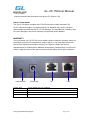
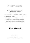
Headset Jack
Power Jack
PC
LAN
Power Jack
PC
5V DC power port; UL Certified
10/100Mbps RJ-45 ports for PC (downlink) connection.
LAN
Headset Jack
10/100Mbps RJ-45 port for LAN (uplink) connection.
3.5mm
Copyright © 2009-2011 GigaLink
Page 6 of 37
GL-VP-150 User Manual
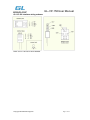
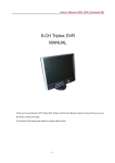
GL-VP-150 interface wiring schema:
Note: GL-VP-150 use 3.5mm headset.
Copyright © 2009-2011 GigaLink
Page 7 of 37
GL-VP-150 User Manual
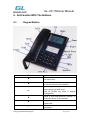
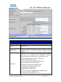
6. Get Familiar With The Buttons
6.1.
Keypad Button
Kepad Buttons
Kepad Buttons Definitions
Return to the last screen and shortcut key
for phone book.
Scroll to previous menu/submenu selection,
or rise the volume of the loudhailer
Enter Keypad Configuration “MENU” mode
when phone is in IDLE mode.
Use as ENTER key when in Keypad
Configuration.
Scroll to next menu/submenu selection, or
lower the volume of the loudhailer
Go to the next screen and shortcut key for
Dialed calls.
Enter to retrieve voice mails or other
messages
Copyright © 2009-2011 GigaLink
Page 8 of 37
GL-VP-150 User Manual
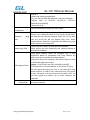
0 - 9, *(.), #
To input: numbers, *(.), #
TRNF
Transfer the present call to another number
HOLD
Hold the present call for the moment
FLASH
Swith the call
CONF
# and SEND
Brings phonebook on screen
Delete the call history, voice message, input
keys, Reject Call,Mute,etc.
Conference call for three sides
Press SEND to dial a new number or redial
the last number dialed. Press send button to
send a call immediately before “no key entry
timeout” value Expires
Enable/Disable hands-free speaker mode
Speed key buttons
Short cut of register call
7. BASIC OPERATIONS
7.1.
7.1.1.
Make Phone call
Handset, Speakerphone and Headset Mode
Handset can be toggled between Speaker and Headset. To switch between Handset and
Speaker/Headset, press the SPEAKER button.
7.1.2. Completing Calls
There are four ways to complete a call:
DIAL: To make a phone call.
• Take Handset/SPEAKER/Headset off-hook
• The phone will have a dial tone and the LCD display the “Dail”.
• Enter the phone number
• Press the SEND key
REDIAL: To redial the last dialed phone number.
Copyright © 2009-2011 GigaLink
Page 9 of 37
GL-VP-150 User Manual
When redialing the phone will use the same SIP account as was used for the last call.
• Take Handset/SPEAKER/Headset off-hook or
• Press the # or SEND button
USING THE CALL HISTORY: To call the a phone number in the phone‟s history
When using the call history, the phone will use the same SIP account as was used for
the last call/call attempt. Thus, when returning a call made to the third SIP account,
the phone will use the third SIP account return the call.
•Press the MENU button to bring up the Main Menu.
•Select Call History and then “Received Calls”, “Missed Calls” or “Dialed Calls”
depending on your needs
• Select phone number using the arrow keys
• Press OK to select
• Press OK again to dial.
USING THE PHONEBOOK: Calling a phone in from the phone‟s phonebook.
• Go to the phonebook by:
.
Pressing the left arrow button (at idle or talking status), or
Pressing the menu button and Selecting “Phone book” and Press MENU
• Select the phone number by using the arrow keys
• Press OK so select
• Press OK again to dial.
7.1.3. Making Calls using IP Addresses
Direct IP calling allows two phones to talk to each other in an ad hoc fashion without a SIP
proxy. VoIP calls can be made between two phones if:
• Both phones have public IP addresses, or
• Both phones are on a same LAN/VPN using private or public IP addresses, or
• Both phones can be connected through a router using public or private IP addresses
(with necessary port forwarding or DMZ)
To make a direct IP call, please follow these steps:
1. Press MENU button to bring up MAIN MENU.
2. Select “Direct IP Call” using the arrow-keys.
3. Press OK to select.
Copyright © 2009-2011 GigaLink
Page 10 of 37
GL-VP-150 User Manual
4. Input the 12-digit target IP address. (Please see example below).
5. Press OK key to initiate call.
To make a quick IP call, please see next section.
For example: If the target IP address is 192.168.1.60 and the port is 5062 (e.g.
192.168.1.60:5062), input the following: 192*168*1*60*5062 - The “ * ” key represent the
dot“.” And colon “:”.
Press OK to dial out
7.1.4. Quick IP Call Mode
The GL-VP-150 also supports Quick IP call mode. This enables the phone to make direct
IP-calls, using only the last few digits (last octet) of the target phone‟s IP-number.
This is possible only if both phones are in under the same LAN/VPN. This simulates a
PBX function using the CMSA/CD without a SIP server. Controlled static IP usage is
recommended.
For example:
192.168.0.2 calling 192.168.0.3 -- dial *473 follow by SEND or #
192.168.0.2 calling 192.168.0.23 -- dial *4723 follow by SEND or #
192.168.0.2 calling 192.168.0.123 -- dial *47123 follow by SEND or #
192.168.0.2: dial *473 and *4703 and *47003 results in the same call -- call 192.168.0.3
NOTE: If you have a SIP Server configured, a Direct IP-IP still works. If you are using
STUN, the Direct IPIP call will also use STUN. Configure the “Use Random Port” to “NO”
when completing Direct IP calls.
7.2.
ANSWERING PHONE CALLS
7.2.1. Receiving Calls
1. Incoming single call: Phone rings with selected ring-tone. The LCD will display the
caller‟s. Answer call by taking Handset/SPEAKER/Headset off hook or pressing
SPEAKER.
2. Incoming multiple calls: When another call comes in while having an active call, the
phone will produce a Call Waiting tone (stutter tone). Answer the incoming call by pressing
the FLASH key. The current active call will be put on hold.
Copyright © 2009-2011 GigaLink
Page 11 of 37
GL-VP-150 User Manual
7.3.
PHONE FUNCTIONS DURING A PHONE CALL
7.3.1. Call Hold
While in conversation, pressing the “Hold” button will put the remote end on hold.
Pressing the “Hold” button again will release the previously Hold state and resume the
bi-directional media.
7.3.2. Call Waiting and Call Flashing
If call waiting feature is enabled, while the user is in a conversation, he will hear a
special stutter tone if there is another incoming call. User then can press FLASH button to
put the current call party on hold automatically and switch to the other call. Pressing flash
button toggles between two active calls.
7.3.3. Call Transfer
GL-VP-150 supports both blind and attended call transfer. Each is easy to use. Use
blind transfer if you want to transfer a call without speaking with someone first; use
attended transfer if you want to speak with the someone prior to transferring call.
7.3.3.1 Blind Transfer
Transfer an active call to a third party without announcement.
Press the TRANSFER button and wait for a dial tone. Dial the third party‟s phone
number followed by the SEND button.
NOTE: The “Enable Call Feature” must be configured to “Yes” in the web configuration
page to enable this feature.
7.3.3.2 Attended Transfer
Transfer an active call to a third party with attended.
Press Flash button and make a call and automatically place the ACTIVE call on HOLD.
Once the call is established, hang up to transfer the call.
NOTE: To transfer calls across SIP domains, SIP service providers must support transfer
across SIP domains. Blind transfer will usually use the primary account.
Copyright © 2009-2011 GigaLink
Page 12 of 37
GL-VP-150 User Manual
7.3.4. Conference Call
GL-VP-150 phone supports 3-way conference.
Assuming that call party A and B are in conversation. A wants to bring C in a
conference:
A presses the “CONFERENCE” button to get a dial tone and put B on hold
A dials C‟s number then “SEND” key to make the call
If C answers the call, then A presses “CONFERENCE” button to bring B, C in the
conference.
If C does not answer the call, A can press FLASH back to talk to B.
NOTE:
During the conference, if B or C drops the call, the remaining two parties can still talk.
However, if A the conference initiator hangs up, all calls will be terminated.
7.3.5. Mute/Delete/Reject incoming calls
1. Press the button to enable/disable muting the microphone.
2. The “Line Status Indicator” will show “LINEx: SPEAKING” or “LINEx: MUTE” to indicate
whether the microphone is muted.
NOTE: Pressing button for an incoming call will reject the call. button also functions
as delete key when user wish to delete the last entered digit.
7.3.6. Voice Messages (Message Waiting Indicator)
A blinking red MWI (Message Waiting Indicator) indicates a message is waiting. Press
the MSG button to retrieve the message. An IVR will prompt the user through the process
of message retrieval.
NOTE:Account requires a voicemail portal number to be configured in the “voicemail user
id” field.
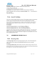
7.3.7. SMS (Short Messaging Service)
The sms can only be used if the SERVER/PBX supports this feature.
If the phone has received a sms, the LCD screen will display the NEW IM.
Press the MENU key, and select the Instand Message, and press OK, the you can check
the Input message.
Copyright © 2009-2011 GigaLink
Page 13 of 37
GL-VP-150 User Manual
7.3.8. Do Not Disturb
The “DND” functinon can be set at config menu to set phone to „do not disturb‟ (it will be
on the screen). The phone will not ring and send caller directly to voicemail.
7.4.
CALL FEATURES
7.4.1. Call Features Tables
Following table shows the call features of GL-VP-150 :
Key
Call Features
*30
Block Caller ID (for all subsequent calls)
*31
Send Caller ID (for all subsequent calls)
*67
Block Caller ID (per call)
*82
Send Caller ID (per call)
*50
Disable Call Waiting (for all subsequent calls)
*51
Enable Call Waiting (for all subsequent calls)
*70
Disable Call Waiting. (Per Call)
*71
Enable Call Waiting (Per Call)
*72
Unconditional Call Forward.
To use this feature, dial “*72” and get the dial tone. Then dial the forward
number and “#” for a dial tone, then hang up.
*73
Cancel Unconditional Call Forward.
To cancel “Unconditional Call Forward”, dial “*73” and get the dial tone,
then hang up.
*90
Busy Call Forward.
To use this feature, dial “*90” and get the dial tone. Then dial the forward
number and “#” for a dial tone, then hang up.
*91
Cancel Busy Call Forward.
To cancel “Busy Call Forward”, dial “*91” and get the dial tone, then hang
up.
*92
Delayed Call Forward.
To use this feature, dial “*92” and get the dial tone. Dial the forward
number and “#” for a dial tone and then hang up.
*93
Cancel Delayed Call Forward.
To cancel this feature, dial “*93”, get the dial tone, and then hang up.
Flash/Hook
call waiting indication.
When in conversation without an incoming call, this action will switch to a
new channel to make a new call.
7.4.2. XML Phonebook
The GL-VP-150 supports a download XML phonebook.
Copyright © 2009-2011 GigaLink
Page 14 of 37
GL-VP-150 User Manual
8. CONFIGURATION GUIDE
8.1.
CONFIGURATION VIA KEYPAD
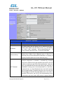
To enter the MENU, press the central button. Navigate the menu by using the arrow keys:
up/down and left/right.
Call History
Displays histories of incoming, dialed and
missed calls.
Phone Book
Displays the New Entry and you can
download the phonebook.
Status
Displays the network status, account
statuses, software version and
MAC-address of the phone.
Instant Message
Goes to instant messages
Direct IP Call
Displays the ip call options menu
Config
Press Menu button to display the
configuration selections:
• Network
To enable/disable DHCP.
To setup IP-address, Net mask and
Gateway address
• Account
• Upgrade
In this menu setting regarding the firmware
server and configure server can be
changed. It also enables the user to make
the phone attempt to download new
firmware.
• Factory Reset
Press Menu button and the Confirm Factory
Reset to reset FACTORY DEFAULT
setting. Do not use Factory Reset unless
you want to restore factory settings
Press „‟ to return the main menu.
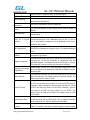
Preference
Press Menu button to enter this sub menu
including
• Ring Tone
Choose different ring tones in the “Ring
Tone” menu.
Copyright © 2009-2011 GigaLink
Page 15 of 37
GL-VP-150 User Manual
• Ring Volume
Press Menu button to hear the selected ring
volume, press „‟ or ‟‟ to hear and adjust
the ring tone volume..
Press „‟ to return to the main menu.
Factory Functions
Press Menu to display the factory function
items including
• Audio Loopback
Speak into the handset. If you hear your
voice in the handset, your audio works fine.
• Diagnostic Mode
All LEDs will light up
Press any key on the keypad, to display the
button name in the LCD. Lift and put back
the handset.
Press „‟ to return to the main menu.
Reboot
Press Menu button to reboot the device
And choose Confirm Reboot or Cancel
Reboot.
The main configuration menu is the Config menu. This menu consists of four submenus
that allow you to configure and display information about the Unicore5001. Table 5 shows
the available menus and their uses.
Configuration Menus and Their Functions
option
Network
Account
Upgrade
Factory Reset
Used To
assign network settings such as the IP
Mode, IP, Netmask and Gateway
assign Account information such as the
SIP Proxy, Outbound Proxy, User ID, Auth
ID, Password, User Name, Audio, Confirm
Save, Return & Cancel.
assign Upgrade Settings such as the
Firmware Server, Configure Server,
Upgrade Via.
Choose whether to restore factory settings
Navigating the Menus
Copyright © 2009-2011 GigaLink
Page 16 of 37
GL-VP-150 User Manual
The following information will help you understand the interface for the configuration
menus.
Press the MENU key to access the Setup menu.
Use the ▲ and ▼ keys to scroll through the menu choices.
When the desired menu option is indicated by →, press the MENU key again to select
the indicated option.
Press the to return to the previous screen.
Network Setting
The Network Setting sub-menu is used to assign network settings such as the IP Mode,
IP, Netmask and Gateway. All sub-menus under Network Setting are password protected
and can be altered only by an administrator. Users may view the information but not
change it.
Step1: Press the MENU key to enter the Setup menu
Step2: Choose the Config sub-menu and press MENU again.
Step3: Choose the Network sub-menu and press MENU
Step4: Chooose the IP Mode sub-menu and press MENU
Step5: Use the ▼ and ▲ keys to choose the mode you want
Then press
to go to the sub-menu IP Mode, and config IP, Netmask, Gateway as
above.
IP display the IP address at the moment, you can input new IP address while the DHCP is
set OFF.(Press MENU key to return to the previous screen.)
Account Setting
The Account Setting sub-menu is used to assign Account information such as the SIP
Proxy, Outbound Proxy, User ID, Auth ID, Password, User Name, Audio, Confirm
Save and Return & Cancel.
Step1: Return to the Config sub-menu
Step2: Choose the Acct sub-menu and press MENU again.
Step3: Choose the SIP Proxy sub-menu and press MENU again.
Step4: Input the valid SIP proxy server and press MENU key to return to the previous
screen.
You can config Outbound Proxy, User ID, Auth ID, Password, User Name, Audio as
Copyright © 2009-2011 GigaLink
Page 17 of 37
GL-VP-150 User Manual
above.(the specifications of these can be found from 8.2.4.4 Account Options) and
choose Confirm Save or Return & Cancel after you finish configuration.
Upgrade Setting
The Upgrade Setting sub-menu is used to assign Upgrade Settings such as the
Firmware Server, Configure Server and Upgrade Via.
Step1: Return to the Config sub-menu.
Step2: Choose the Upgrade sub-menu and press MENU again.
Step3: Choose the Firmware Server sub-menu and press MENU again.
Step4: Input the valid Firmware Server and press MENU key to return to the previous
screen
You can config Configure Server, Upgrade Via as above. (the specifications of these can
be found from 8.2.4.3 Super Options )
Factory Reset Setting
Step1: Return to the Config sub-menu.
Step2: Choose the Factory Reset sub-menu and press MENU again.
Step3:Choose Confirm Factory Reset or Cancel Factory Reset.
8.2.
Configuring GL-VP-150 using Web Browser
GL-VP-150 has embedded Web server and HTML pages that allow users to configure
the GL-VP-150 through an easy-to-use Web browser interface such as Microsoft‟s
Internet Explorer or Netscape browser. Below is a screen shot of the GL-VP-150
configuration page:
8.2.1. Accessing the Web Configuration
The GL-VP-150 configuration page can be accessed via your web browser by entering
the WAN IP address:
http://192.168.0.13
Be sure that your PC is connected to the router/hub/switch directly .
Copyright © 2009-2011 GigaLink
Page 18 of 37
GL-VP-150 User Manual
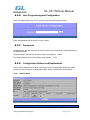
8.2.2. User Programming and Configuration
From your web browser, the GL-VP-150 will show the following login screen:
Enter the password and click on the “Login” button
8.2.3. Passwords
Passwords are case sensitive and all GL-VP devices come with factory default passwords
as indicated below:
Advanced User Password for access to Super User Options: admin
End User Password for access to Basic User Options: 1234
8.2.4. Configuration Options and Explanations
After a correct password is entered in the login screen, the embedded web server inside
the GL-VP-150 will show the configuration page, which is explained in details below:
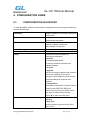
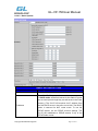
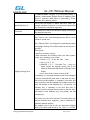
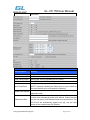
8.2.4.1 Device Status
Device Status
Copyright © 2009-2011 GigaLink
Page 19 of 37
GL-VP-150 User Manual
Options
Meaning
MAC Address
The device ID, in HEX format.This is a very important ID for ISP
troubleshooting.
WAN IP Address
This field shows IP address of GL-VP-150.
Product Model
Contains the product model info.
Software Version
.• Program: This is the main software (firmware) release number,
always used to identify the software (firmware) system of the phone.
• Boot: Booting code version number
System Up Time
Shows system up time since the last reboot.
PPPoE Link Up
Indicates whether the PPPoE connection is enabled (connected to a
modem).
NAT
Indicates the type of NAT connection used by the GL-VP-150 via its
WAN port.
Based on STUN protocol.
Shows several information regarding the individual FXS ports.
Account
Port Status
Registratio
DND
n
Account 1
Registered
Forward
Busy
Delayed
Forward
Forward
No
Indicates whether account are registered to the related SIP
server(s).
Copyright © 2009-2011 GigaLink
Page 20 of 37
GL-VP-150 User Manual
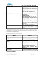
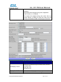
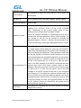
8.2.4.2 Basic Options
BASIC OPTIONS SETTING
Options
Meaning
Web Port
Default is 80.
IP Address
There GL-VP-150 operates in two modes:
1. DHCP mode: all the field values for the Static IP mode
are not used (even though they are still saved in the Flash
memory.) The GL-VP-150 acquires its IP address from
the first DHCP server it discovers on its LAN. The DHCP
option is reserved for NAT router mode. To use the
PPPoE feature, set the PPPoE account settings. The
GL-VP-150 establishes a PPPoE session if any of the
PPPoE fields are set.
Copyright © 2009-2011 GigaLink
Page 21 of 37
GL-VP-150 User Manual
2. Static IP mode: configure all of the following fields: IP
address, Subnet Mask, Default Router IP address, DNS
Server 1 (primary), DNS Server 2 (secondary). These
fields are set to zero by default.
Speed Dail Key1~6
GL-VP-150 has define 6 speed dial keys. After you
program numbers for this key. You can touch a speed dial
key and then the call will be originated.
Time Zone
This parameter controls the date/time display according to
the specified time zone.
This parameter controls time displayed in daylight savings
time. If set to “Yes”, then the displayed time will be 1 hour
ahead of normal time.
Daylight Savings Time
The “Optional Rule” is configured to automatically adjust
the Daylight Savings Time (DST) based on the rule set in
this field.
Rule Syntax:
• start-time; end-time; saving
• Both start-time and end-time have the same syntax:
month, day, weekday, hour, minute
o month: 1,2,3,..,12 (for Jan, Feb, .., Dec)
o day: [+|-]1,2,3,..,31
o weekday: 1, 2, 3, .., 7 (for Mon, Tue, .., Sun), or 0
which means the daylight saving rule is not
based on week days but based on the day of the
month.
o hour: hour (0-23), minute: minute (0-59)
If “weekday” is 0, it means the date to start or end daylight
saving is at exactly the given date. In that case, the “day”
value must not be negative. If “weekday” is not zero and
“day” is positive, then the daylight saving starts on the first
“day” the iteration of the weekday (e.g.: 1st Sunday, 3rd
Tuesday etc). If “weekday” is not zero and “day” is
negative, then the daylight saving starts on the last “day”
the iteration of the weekday (e.g.: last Sunday, 3rd last
Tuesday etc).
The saving is in the unit of minutes. The saving time may
also be preceded by a negative (-) sign if subtraction is
desired instead of addition.
The default value is set for US, the “Automatic Daylight
Saving Time Rule” shall be set to “3,2,7,2,0;11,1,7,2,0;60”
Copyright © 2009-2011 GigaLink
Page 22 of 37
GL-VP-150 User Manual
Examples
US/Canada where daylight saving time is applicable:
03,02,7,02,00;11,1,7,02,00;60
This means the daylight saving time starts from the
second Sunday of March at 2AM and ends the first
Sunday of November at 2AM. The saving is 60 minutes.
BASIC OPTIONS SETTING
Options
Meaning
Date Display Format
Allow user to choose among the following three formats:
Year-Month-Day
Month-Day-Year
Day-Month-Year
Display info of LCD
You can select displaying ip address or you can custimize it.
Device Mode
To use the device as a router or a bridge.
Copyright © 2009-2011 GigaLink
Page 23 of 37
GL-VP-150 User Manual
LAN Subnet Mask
Sets the LAN subnet mask. Default value is 255.255.255.0
LAN DHCP Base IP:
Base IP for the LAN port which functions as a Gateway for
the subnet. Default value is 192.168.22.1
DHCP IP Lease Time:
Value is set in units of hours. Default value is 120hr (5
Days) The time IP address are assigned to the LAN clients
DMZ IP:
Forward all WAN IP traffic to a specific IP address if no
matching port is used by GL-VP-150 itself or in the defined
port forwarding
Port Map
Allow user to forward a matching (TCP/UDP) port to a
specific LAN IP address with a specific (TCP/UDP) port.
End User Password
This contains the password to access the
Configuration Menu. This field is case sensitive.
Web
If set to “Yes”, the GL-VP-150 will respond to the PING
Reply to ICMP on WAN
command from other computers, but it also is vulnerable to
port
the DOS attack. Default is No.
Wan Side Http Access
If this parameter is set to “No”, the HTML configuration
update via WAN port is disabled.
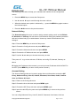
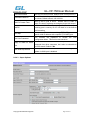
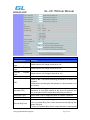
8.2.4.3 Super Options
Copyright © 2009-2011 GigaLink
Page 24 of 37
GL-VP-150 User Manual
Super Options
Setting Options
Meaning
Admin Password
Administrator password. Only the administrator can access
the “Super Options” and “Account Settings” page. Password
field is purposely blank for security reasons after clicking
update and saved. The maximum password length is 25
characters.
STUN server is:
IP address or Domain name of the STUN server.
Keep-alive interval
This parameter specifies how often the GL-VP-150 sends a
blank UDP packet to the SIP server in order to keep the “hole”
on the NAT open. Default is 20 seconds. Minimum value is 20
seconds.
No Key Entry Timeout
Default is 4 seconds.
Layer3 Qos
This field defines the layer 3 QoS parameter which can be the
value used for IP Precedence or Diff-Serv or MPLS. Default
value is 48.
Layer2 Qos(VOIP)
Value used for layer 2 VLAN tag. Default setting is blank
Layer2 Qos (PC)
Layer 2 QoS settings for LAN port device traffic. Default
setting is blank.
VLAN supported equipment is required if user needs to
change these settings.
Firmware Upgrade
Support firmware upgrade via TFTP or HTTP,
Support for Authenticating configuration file before accepting
changes
User specific URL for configuration file and firmware files
Phonebook XML
Enable the XML phonebook via TFTP or HTTP. Define XML
server path and download speed.
NTP server
URI or IP address of the NTP (Network Time Protocol) server.
Used by the phone to synchronize the date and time.
Default is “No”. If set to “Yes”, configuration file would be
Authenticate Conf File
authenticated before acceptance. End user should use default
setting.
Copyright © 2009-2011 GigaLink
Page 25 of 37
GL-VP-150 User Manual
Super Options
Setting Options
Lock Keypad Update
If set to “Yes”, the configuration update via keypad is disabled.
Disable
Prompt
Default is No
Voice
Syslog Sever
The IP address or URL of System log server. This feature is
especially useful for the ITSP (Internet Telephone Service
Provider)
Syslog level
Select the GL-VP-150 to report the log level. Default is NONE.
The level is one of DEBUG, INFO, WARNING or ERROR.
Syslog messages are sent based on the following events:
1. product model/version on boot up (INFO level)
2. NAT related info (INFO level)
3. sent or received SIP message (DEBUG level)
4. SIP message summary (INFO level)
5. inbound and outbound calls (INFO level)
6. registration status change (INFO level)
7. negotiated codec (INFO level)
8. Ethernet link up (INFO level)
9. SLIC chip exception (WARNING and ERROR levels)
10. memory exception (ERROR level)
The Syslog uses USER facility. In addition to standard Syslog
Copyright © 2009-2011 GigaLink
Page 26 of 37
GL-VP-150 User Manual
payload, it
contains the following components:
GS_LOG: [device MAC address][error code] error message
Example: May 19 02:40:38 192.168.1.14 GS_LOG:
[00:0b:82:00:a1:be][000]
Ethernet link is up
Download
Device
Configuration
Used to download the change you have made.
Distinctive
Tone
Caller ID must be configured. Select a Distinctive Ring Tone 1
through 3 for a particular Caller ID. The GL-VP-150 will ONLY
use selected ring tones for particular Caller IDs. For all other
calls, the GL-VP-150 will use System Ring Tone. When
selected and no Caller ID is configured, the selected ring tone
will be used for all incoming calls.
Ring
System Ring Tone
System ring tone. Default is North American standard.
Adjust system ring tone frequencies and cadences based on
local telecom standard.
Call Progress Tones
Using these settings, users can configure ring or tone
frequencies based on parameters from local telecom. By
default, they are set to North American standard.
Frequencies should be configured with known values to avoid
uncomfortable high pitch sounds.
Syntax: f1=val,f2=val[,c=on1/off1[-on2/off2[-on3/off3]]];
(Frequencies are in Hz and cadence on and off are in 10ms)
ON is the period of ringing (“On time” in „ms‟) while OFF is the
period of silence. In order to set a continuous ring, OFF should
be zero. Otherwise it will ring ON ms and a pause of OFF ms
and then repeat the pattern. Up to three cadences are
supported.
Restore
Configuration
User can restore the before configuration from the configuration
file saved at local pc
Copyright © 2009-2011 GigaLink
Page 27 of 37
GL-VP-150 User Manual
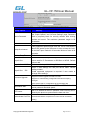
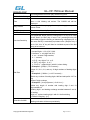
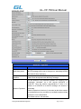
8.2.4.4 Account
Options
Account 1 Options
Settings Options
Meaning
Account active
When set to Yes the FXS port is activated
SIP Server
This field contains the URI string or the IP address (and port, if
different from 5060) of the SIP proxy server. e.g., the following
are some valid examples: sip.my-voip-provider.com, or
sip:my-company-sip-server.com, or 192.168.1.200:5066
Outbound Proxy
This field contains the URI string or the IP address (and port, if
different from 5060) of the outbound proxy. If there is no
outbound proxy, this field SHOULD be left blank. If not blank, all
outgoing requests will be sent to this outbound proxy.
NAT Traversal
This parameter defines whether or not the GL-VP-150 NAT
traversal mechanism is activated. If activated (by choosing
“Yes”) and a STUN server is also specified, then the GL-VP-150
performs according to the STUN client specification. Using this
mode, the embedded STUN client will detect if and what type of
firewall/NAT is being used. If the detected NAT is a Full Cone,
Restricted Cone, or a Port-Restricted Cone, the GL-VP-150 will
use its mapped public IP address and port in all of its SIP and
SDP messages. If the NAT Traversal field is set to “Yes” with no
specified STUN server, the GL-VP-150 will periodically (every
20 seconds or so) send a blank UDP packet no payload data) to
Copyright © 2009-2011 GigaLink
Page 28 of 37
GL-VP-150 User Manual
the SIP server to keep the “hole” on the NAT open.
SIP User ID
SIP service subscriber‟s User ID
Authenticate ID
SIP service subscriber‟s Authenticate ID. Can be identical to or
different from SIP User ID
Authenticate
Password
SIP service subscriber‟s account password
Name
SIP service subscriber‟s name which will be used for Caller ID
display
Use DNS SRV
Default is No. If set to Yes the client will use DNS SRV for
server lookup
If the GL-VP-150 has an assigned PSTN telephone number, this
User ID is Phone field should be set to “Yes”. Otherwise, set it to “No”. If “Yes” is
Number
set, a “user=phone” parameter will be attached to the “From”
header in SIP request
This parameter controls whether the GL-VP-150 needs to send
REGISTER messages to the proxy server. The default setting is
“Yes”.
SIP Registration
Unregister
Reboot
on Default is “No.” If set to “Yes”, then the SIP user will be
unregistered on reboot.
Register Expiration
This parameter allows the user to specify the time frequency (in
minutes) the GL-VP-150 refreshes its registration with the
specified registrar. The default interval is 60 minutes (or 1 hour).
The maximum interval is 65535 minutes (about 45 days).
Default is No. If set to “Yes,” user can place outgoing calls even
Outgoing call without
when not registered (if allowed by ITSP) but is unable to receive
Registration
incoming calls.
Local SIP port
This parameter defines the local SIP port the GL-VP-150 will
listen and transmit. The default value for FXS port is 5060. The
default value for FXO port is 5062.
Local RTP port
This parameter defines the local RTP-RTCP port pair the
GL-VP-150 will listen and transmit. It is the base RTP port for
channel 0. When configured, channel 0 will use this port _value
for RTP and the port_value+1 for its RTCP; channel 1 will use
port_value+2 for RTP and port_value+3 for its RTCP. The
default value for FXS port is 5004. The default value for FXO
port is 5008.
Use Random Port
This parameter, when set to Yes, will force random generation
of both the local SIP and RTP ports. This is usually necessary
when multiple GL-VP-150 are behind the same NAT.
Refer-To Use Target Default is NO. If set to YES, then for Attended Transfer, the
Contact
“Refer-To” header uses the transferred target‟s Contact header
Copyright © 2009-2011 GigaLink
Page 29 of 37
GL-VP-150 User Manual
information.
Account 1 Options
Settings Options
Meaning
DTMF Payload Type
This parameter sets the payload type for DTMF using RFC2833
DTMF in Audio
Send DTMF as inband (in-audio).
DTMF via RFC2833
Send DTMF via RTP (According to RFC 2833).
DTMF via SIP INFO
Send DTMF via SIP INFO message.
Send Flash Event
This parameter allows users to control whether to send an SIP
NOTIFY message indicating the Flash event, or just to switch to
the voice channel when users press the Flash key.
Enable Call Features
Default is No. If set to Yes, Call Forwarding & Do-Not-Disturb are
supported locally
Offhook Auto-Dial
This parameter allows users to configure a User ID or extension
number to be automatically dialed upon offhook. Please note that
only the user part of a SIP address needs to be entered here. The
GL-VP-150 will automatically append the “@” and the host
portion of the corresponding SIP address.
Copyright © 2009-2011 GigaLink
Page 30 of 37
GL-VP-150 User Manual
Proxy-Require
SIP Extension to notify SIP server that the unit is behind the
NAT/Firewall.
USE NAT IP
NAT IP address used in SIP/SDP message. Default is blank.
Disable call-waiting
Default is No.
Preferred Vocoder
The GL-VP-150 supports up to 7 different Vocoder types
including G.711 A-/U-law,G.723.1, G.726, G.728, G.729A/B,
iLBC.
Depending on the product model, some of these
Vocoders may not be provided in standard release.
Users can configure Vocoders in a preference list that will be
included with the same preference order in SDP message. The
first Vocoder in this list can be entered by choosing the
appropriate option in “Choice 1”. Similarly, the last Vocoder in this
list can be entered by choosing the appropriate option in “Choice
7”.
This field contains the number of voice frames to be transmitted
in a single packet. When setting this value, the user should be
aware of the requested packet time (used in SDP message) as a
result of configuring this parameter. This parameter is associated
with the first vocoder in the above vocoder Preference List or the
actual used payload type negotiated between the 2 conversation
parties at run time. e.g., if the first vocoder is configured as G723
and the “Voice Frames per TX” is set to be 2, then the “ptime”
value in the SDP message of an INVITE request will be 60ms
Voice Frames per TX because each G723 voice frame contains 30ms of audio.
Similarly, if this field is set to be 2 and if the first vocoder chosen
is G729 or G711 or G726, then the “ptime” value in the SDP
message of an INVITE request will be 20ms. If the configured
voice frames per TX exceeds the maximum allowed value, the
GL-VP-150 will use and save the maximum allowed value for the
corresponding first vocoder choice. The maximum value for PCM
is 10(x10ms) frames; for G726, it is 20 (x10ms) frames; for G723,
it is 32 (x30ms) frames; for G729/G728, 64 (x10ms) and 64
(x2.5ms) frames respectively.
G723 Rate
This defines the encoding rate for G723 vocoder. By default,
6.3kbps rate is chosen.
Copyright © 2009-2011 GigaLink
Page 31 of 37
GL-VP-150 User Manual
Account 1 Options
Settings Options
Meaning
G726-16
Type
Payload
Default value is 98. Range is from 96 to 127.
G726-24
Type
Payload
G726-40
Type
Payload
Default value is 99. Range is from 96 to 127.
Default value is 103. Range is from 96 to 127.
G729E Payload Type
Default value is 102. Range is from 96 to 127.
VAD
Default is No. VAD allows detecting the absence of audio and
conserve
bandwidth by preventing the transmission of "silent packets" over
the network.
Symmetric RTP
Default is No. When set to Yes the device will change the
destination to send RTP packets to the source IP address and
port of the inbound RTP packet last received by the device.
Jitter Buffer Type
Select either Fixed or Adaptive based on network conditions.
Jitter Buffer Length
Select Low, Medium or High based on network conditions.
Account Ring Tone
There are 4 uniquely defined ring tones:
• One (1) System Ring Tone: when selected, all calls will ring with
system ring tone.
• Three (3) Customer Ring Tones: when selected, incoming calls
Copyright © 2009-2011 GigaLink
Page 32 of 37
GL-VP-150 User Manual
from designated account will play selected ring tone.
Disable Call -Waiting
Default is No.
Disable Call –Waiting Default is No. This is to disable the stutter Call Waiting Tone
Tone
when a Call Waiting call arrives. The CWCID will still be
displayed.
Ring Timeout
Incoming call will stop ringing when not picked up given a specific
period of time.
Early Dial
Default is No. Use only if proxy supports 484 response
Dial Plan Prefix
Sets the prefix added to each dialed number
Use # as Send Key
This parameter allows users to configure the “#” key to be used
as the “Send” (or “Dial”) key. If set to “Yes”, pressing this key will
immediately trigger the sending of dialed string collected so far. In
this case, this key is essentially equivalent to the “(Re)Dial” key. If
set to “No”, this “#” key will then be included as part of the dial
string to be sent out.
Dial Plan
Dial Plan Rules:1. Accept Digits: 1,2,3,4,5,6,7,8,9,0
2. Grammar: x - any digit from 0-9;
a. xx+ - at least 2 digit number;
b. ^ - exclude;
c. [3-5] - any digit of 3, 4, or 5;
d. [147] - any digit 1, 4, or 7;
e. <2=011> - replace digit 2 with 011 when dialing
• Example 1: {[369]11 | 1617xxxxxxx} –
Allow 311, 611, 911, and any 10 digit numbers of leading digits
1617
• Example 2: {^1900x+ | <=1617>xxxxxxx} –
Block any number of leading digits 1900 and add prefix 1617 for
any
dialed 7 digit numbers
• Example 3: {1xxx[2-9]xxxxxx | <2=011>x+} –
Allow any length of number with leading digit 2 and 10
digit-numbers of
leading digit 1 and leading exchange number between 2 and 9;
If leading
digit is 2, replace leading digit 2 with 011 before dialing
3. Default: Outgoing - {x+}
Subscribe for MWI
Default is No. When set to “Yes” a SUBSCRIBE for Message
Waiting Indication will be sent periodically.
Copyright © 2009-2011 GigaLink
Page 33 of 37
GL-VP-150 User Manual
Account 1 Options
Settings Options
Meaning
Send Anonymous
If this parameter is set to “Yes”, the “From” header in outgoing
INVITE message will be set to anonymous, essentially blocking
the Caller ID from displaying.
Anonymous
Rejection
Call Default is No. If set to Yes, incoming calls with anonymous
Caller ID will be rejected with 486 Busy message.
Sesstion Expiration
The SIP Session Timer extension enables SIP sessions to be
periodically “refreshed” via a SIP request (UPDATE, or
re-INVITE. Once the session intervaexpires, if there is no
refresh via a UPDATE or re-INVITE message, the session is
terminated.
Session Expiration is the time (in seconds) at which the session
is considered timed out, provided no successful session refresh
transaction occurs beforehand.
The default value is 180 seconds.
Copyright © 2009-2011 GigaLink
Page 34 of 37
GL-VP-150 User Manual
Defines the minimum session expiration (in seconds). Default is
90 seconds.
Min-SE
Caller
Timer
Request If set to “Yes”, the phone will use session timer when it makes
outbound calls if remote party supports session timer.
Callee Request
Timer
If selecting “Yes”, the phone will use session timer when it
receives inbound calls with session timer request.
Force Timer
If set to “Yes”, the phone will use session timer even if the
remote party does not support this feature. If set to “No”, the
session timer is enabled only when the remote party supports
this feature. To turn off Session Timer, select “No” for Caller
Request Timer, Callee Request Timer, and Force Timer.
UAC
Refresher
Specify As a Caller, select UAC to use the phone as the refresher, or
UAS to use the Callee or proxy server as the refresher.
UAS
Refresher
Specify As a Callee, select UAC to use caller or proxy server as the
refresher, or UAS to use the phone as the refresher.
Force Invite
Session Timer can be refreshed using INVITE method or
UPDATE method. Select “Yes” to use INVITE method to refresh
the session timer.
Special Feature
Default is Standard. Choose the selection to meet some special
requirements from Soft Switch vendors like Lucent FS5000
Simple Endpoint, CBCOM, etc.
8.2.5. Saving the Configuration Changes
Once a change is made, users should click on the “SaveSet” button in the Configuration
page, as follow:
The GL-VP-150 will then display the following screen to confirm that the changes have
been saved. Please allow 5 to 10 seconds before rebooting the device.
Copyright © 2009-2011 GigaLink
Page 35 of 37
GL-VP-150 User Manual
8.2.6. Rebooting the GL-VP-150
You can reboot the GL-VP-150 by clicking on the “Reboot” button after each update to the
configuration page. Alternatively, you can reboot by unplugging the power supply of the
GL-VP-150 and then powering it on again. If your GL-VP-150 ever becomes “stuck” or
un-responsive, you can unplug the power supply to reboot it. Frequent rebooting by
unplugging the power supply is not recommended and should not be necessary.
8.2.7. Configuration through a Central Server
GL-VP-150 devices can be automatically configured from a central provisioning system.
When GL-VP-150 boots up, it will send TFTP or HTTP request to download configuration
files. There are two configuration files, one is “cfg.txt” and the other is“cfg001fc1xxxxxx”,
where “001fc1xxxxxx” is the MAC address of the GL-VP-150.
For more information regarding configuration file format, please refer to the related
technical documentation.
The configuration file can be downloaded via TFTP or HTTP from the central server. A
service provider or an enterprise with large deployment of GL-VP-150s can easily manage
the configuration and service provisioning of individual devices remotely and automatically
from a central server. The central provisioning system uses enhanced (NAT friendly)
TFTP or HTTP (thus no NAT issues) and other communication protocols to communicate
with each individual GL-VP-150 for firmware upgrade, etc.
9. SOFTWARE UPGRADE
To upgrade software, GL-VP-150 can be configured with a TFTP server where the new
code image is located. The TFTP upgrade can work in either static IP or DHCP mode
using private or public IP address. It is recommended to set the TFTP server address in
either a public IP address or on the same LAN with the GL-VP-150.
There are two ways to set up the TFTP server to upgrade the firmware, namely through
voice menu prompt or via the GL-VP-150 ‟s Web configuration interface. To configure the
TFTP server via voice prompt, follow section 8.1, once set up the TFTP IP address, power
cycle the GL-VP-150, the firmware will be fetched once the GL-VP-150 boots up.
To configure the TFTP server via the Web configuration interface, open up your browser to
point at the IP address of the GL-VP-150. Input the admin password to enter the
configuration screen. From there, enter the TFTP server address in the designated field
towards the bottom of the configuration screen.
Once the TFTP server is configured, please power cycle the GL-VP-150.
TFTP process may take as long as 1 to 2 minutes over the Internet, or just 20+ seconds if
it is performed on a LAN. Users are recommended to conduct TFTP upgrade in a
Copyright © 2009-2011 GigaLink
Page 36 of 37
GL-VP-150 User Manual
controlled LAN environment if possible. For those who do not have a local TFTP server,
GigaLink provides a NAT-friendly TFTP server on the public Internet for firmware upgrade.
Please check the Service section of GigaLink‟s Web site to obtain this TFTP server‟s IP
address.
NOTES:
When GigaLink IP Phone boot up, it will send TFTP or HTTP request to download
configuration files, there are two configuration files, one is “cfg.txt” and the other is
“cfg001fc1xxxxxx”, where “001fc1xxxxxx” is the MAC address of the GL-VP-150 . These
two files are for initial automatically provisioning purpose only, for normal TFTP or HTTP
firmware upgrade, the following error messages in a TFTP or HTTP server log can be
ignored.
10.
RESTORE TO FACTORY DEFAULT SETTINGS
Warning:
Restoring to the factory default settings will delete all configuration information of the
device.
Steps to follow in restoring to factory default settings:
Step1: Return to the Config sub-menu.
Step2: Choose the Factory Reset sub-menu and press MENU again.
Step3:Choose Confirm Factory Reset or Cancel Factory Reset.
11.
TECHNICAL SUPPORT CONTACT
Email: [email protected]
Copyright © 2009-2011 GigaLink
Page 37 of 37