1
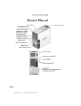
Dell™ XPS 600
Owner’s Manual
Model WHL
w w w. d e l l . c o m | s u p p o r t . d e l l . c o m
Notes, Notices, and Cautions
NOTE: A NOTE indicates important information that helps you make better use of your computer.
NOTICE: A NOTICE indicates either potential damage to hardware or loss of data and tells you how to avoid the
problem.
CAUTION: A CAUTION indicates a potential for property damage, personal injury, or death.
If you purchased a Dell™ n Series computer, any references in this document to Microsoft® Windows®
operating systems are not applicable.
____________________
Information in this document is subject to change without notice.
© 2005 Dell Inc. All rights reserved.
Reproduction in any manner whatsoever without the written permission of Dell Inc. is strictly forbidden.
Trademarks used in this text: Dell, the DELL logo, Inspiron, Dell Precision, Dimension, OptiPlex, Latitude, PowerEdge, PowerVault, and
PowerApp are trademarks of Dell Inc.; Intel and Pentium are registered trademarks of Intel Corporation; Microsoft and Windows are registered
trademarks of Microsoft Corporation.
Other trademarks and trade names may be used in this document to refer to either the entities claiming the marks and names or their products.
Dell Inc. disclaims any proprietary interest in trademarks and trade names other than its own.
Model WHL
November 2005
P/N HC098
Rev. A03
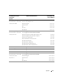
Contents
Finding Information
1
. . . . . . . . . . . . . . . . . . . . . . . . . . . . . . . .
9
Setting Up and Using Your Computer
Opening the Drive Door
. . . . . . . . . . . . . . . . . . . . . . . . . . . . .
15
Changing the Front-Panel Light Color .
. . . . . . . . . . . . . . . . . . . . .
15
Using a Media Card Reader (Optional)
. . . . . . . . . . . . . . . . . . . . .
17
. . . . . . . . . . . . . . . . . . . . . . . . . . . . . .
18
Connecting Monitors .
Connecting a Monitor to a PCI Express Graphics Card
Dual Configuration . . . . . . . . . . . . . . . . . . . .
Connecting Two Monitors . . . . . . . . . . . . . . . .
Connecting a TV . . . . . . . . . . . . . . . . . . . . .
Changing the Display Settings to Support Two Monitors
About Serial ATA Drives
. . . . . . . . .
18
18
20
20
. . . . . . . . . . . . . . . . . . . . . . . . . . . . .
21
About Your RAID Configuration
. . . . . . . . .
. . . . . . . . .
. . . . . . . . .
. . . . . . . . . . . . . . . . . . . . . . . . .
. . . . . . .
. . . . . . . . . . . . . . . . .
27
. . . . . . . . . . . . . . . . . . . . . . . . . . . . .
28
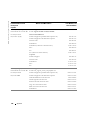
Transferring Information to a New Computer .
Playing CDs and DVDs .
. . . . . . .
. . . . . . .
. . . . . . .
. . . . . . . . . . . . . . . . . . . . . . . . . . .
. . . . . . . . . . . . . . . . . . . . . . . . . . . . .
30
. . . . . . . . . . . . . . . . . . . . . . . . . . .
. . . . . . . . . . . . . . . . . . . . . . . . . . .
. . . . . . . . . . . . . . . . . . . . . . . .
30
31
32
. . . . . . . . . . . . . . . . . . . . . . . . . . . . .
32
How to Copy a CD or DVD. .
Using Blank CDs and DVDs .
Helpful Tips . . . . . . . . .
Network Setup Wizard .
. . . . . . .
28
29
30
Playing a CD or DVD .
Adjusting the Volume .
Adjusting the Picture .
Copying CDs and DVDs.
21
21
22
23
23
24
RAID Level 0 Configuration . . . . . . . . . . . . . . . . . .
RAID Level 1 Configuration . . . . . . . . . . . . . . . . . .
Configuring Your Hard Drives for RAID . . . . . . . . . . . .
Creating an Array using the Nvidia MediaShield ROM Utility
Using Nvidia MediaShield . . . . . . . . . . . . . . . . . .
. . . . . . . . . . . . . . . . . . . . . . . .
. . . . . . . . . . . . . . . . . . . . . . . .
Contents
3
Power Management
. . . . . . . . . . . . . . . . . . . . . . . . . . . . . . .
2
. . . . . . . . . . . . . . . . . . . . . . . . .
Hyper-Threading .
. . . . . . . . . . . . . . . . . . . . . . . . . . . . . . . .
37
PCI Express Cards
. . . . . . . . . . . . . . . . . . . . . . . . . . . . . . . .
37
. . . . . . . . . . . . . . . . . . . . . . . . .
. . . . . . . . . . . . . . . . . . . . . . . . .
. . . . . . . . . . . . . . . . . . . . . . . . .
Optimizing Performance
NVIDIA SLI Dual Graphics Technology
3
. . . . . . . . . . . . . . . . . . . . .
38
. . . . . . . . . . . . . . . . . . . . . . . . . . . . . .
39
. . . . . . . . . . . . . . . . . . . . . . . . . . . . . . . .
39
. . . . . . . . . . . . . . . . . . . . . . . . . . . . . . . . .
39
Solving Problems
Troubleshooting Tips .
Battery Problems .
Drive Problems .
CD and DVD drive problems
Hard drive problems . . . .
. . . . . . . . . . . . . . . . . . . . . . . .
. . . . . . . . . . . . . . . . . . . . . . . .
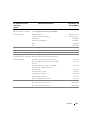
Error Messages
40
41
. . . . . . . . . . . . . . . . . . . .
41
. . . . . . . . . . . . . . . . . . . . . . . . . . . . . . . . .
42
E-Mail, Modem, and Internet Problems .
. . . . . . . . . . . . . . . . . . . . . . . . . . .
43
. . . . . . . . . . . . . . . . . . . . . . . . . . . . . . .
44
IEEE 1394 Device Problems
Keyboard Problems
Lockups and Software Problems
. . . . . . . . . . . . . . . . . . . . . . . .
44
. . . .
45
45
45
45
46
46
46
Memory Problems
. . . . . . . . . . . . . . . . . . . . . . . . . . . . . . . .
47
Mouse Problems .
. . . . . . . . . . . . . . . . . . . . . . . . . . . . . . . .
47
The computer does not start up . . . . . . . . . . . . . . . . . .
The computer stops responding . . . . . . . . . . . . . . . . . .
A program stops responding . . . . . . . . . . . . . . . . . . . .
A program crashes repeatedly . . . . . . . . . . . . . . . . . . .
A program is designed for an earlier Windows operating system .
A solid blue screen appears . . . . . . . . . . . . . . . . . . . .
Other software problems . . . . . . . . . . . . . . . . . . . . . .
4
33
33
33
33
34
Overview . . . . . . . . .
Standby Mode . . . . . .
Hibernate Mode . . . . . .
Power Options Properties
Contents
. . . .
. . . .
. . . .
. . . .
. . . .
. . . .
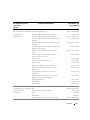
Network Problems .
Power Problems
. . . . . . . . . . . . . . . . . . . . . . . . . . . . . . .
48
. . . . . . . . . . . . . . . . . . . . . . . . . . . . . . . . .
49
Printer Problems .
. . . . . . . . . . . . . . . . . . . . . . . . . . . . . . . .
50
Scanner Problems
. . . . . . . . . . . . . . . . . . . . . . . . . . . . . . . .
51
Sound and Speaker Problems .
. . . . . . . . . . . . . . . . . . . . . . . . .
No sound from speakers . .
No sound from headphones
Video and Monitor Problems
. . . . . . . . . . . . . . . . . . . . . . . .
. . . . . . . . . . . . . . . . . . . . . . . . . .
53
. . . . . . . . . . . . . . . . . . . . . .
53
53
54
. . . . . . . . . . . . . . . . . . . . . . . . . . . . . . . .
55
. . . . . . . . . . . . . . . . . . . . . . . . . . . . . . . . .
58
If the screen is blank . . . . . .
If the screen is difficult to read .
If 3-D image quality is poor . . .
4
51
51
52
. . . . . . . . . . . . . . . . . . . . . . . .
. . . . . . . . . . . . . . . . . . . . . .
. . . . . . . . . . . . . . . . . . . . . .
Advanced Troubleshooting
Diagnostic Lights.
Dell Diagnostics
. . . . . . . . . . . . . . . . . . . . .
58
. . . . . . . . . . . . . . . . . . . . . . . . . . . . . . . . . . . . . .
60
When to Use the Dell Diagnostics
Drivers
What Is a Driver? . .
Identifying Drivers .
Reinstalling Drivers .
. . . . . . . . . . . . . . . . . . . . . . . . . . . .
. . . . . . . . . . . . . . . . . . . . . . . . . . . .
. . . . . . . . . . . . . . . . . . . . . . . . . . . .
Using Microsoft® Windows® XP System Restore
. . . . . . . . . . . . . . .
60
60
61
62
. . . . . . . . . .
63
63
63
. . . . . . . . . . . . .
64
Reinstalling Microsoft® Windows® XP . . . . . . . . . . . . . . . . . . . . .
64
Creating a Restore Point . . . . . . . . . . . . . . . .
Restoring the Computer to an Earlier Operating State .
Undoing the Last System Restore. . . . . . . . . . . .
Resolving Software and Hardware Incompatibilities
Before You Begin . . . . .
Reinstalling Windows XP .
. . . . . . . . . .
. . . . . . . . . .
. . . . . . . . . . . . . . . . . . . . . . . . .
. . . . . . . . . . . . . . . . . . . . . . . . .
64
65
Contents
5
5
Removing and Installing Parts
Before You Begin .
. . . . . . . . . . . . . . . . . . . . . . . . . . . . . . . .
. . . . . . . . . . . . . . . . . .
69
69
70
. . . . . . . . . . . . . . . . . . . . .
71
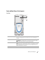
Front View . . . . . . . .
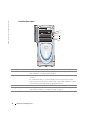
Front View (Doors Open)
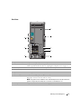
Back View . . . . . . . .
. . . . . . . . . . . . . . . . . . . . . . . . . .
. . . . . . . . . . . . . . . . . . . . . . . . . .
71
72
73
Opening the Computer Cover
. . . . . . . . . . . . . . . . . . . . . . . . . .
76
Recommended Tools . . . . . . . . . .
Turning Off Your Computer . . . . . . .
Before Working Inside Your Computer .
Front and Back View of the Computer .
77
. . . . . . . . . . . . . . . . . . . . . . . . . . .
78
. . . . . . . . . . . . . . . . . . . . . . . . . . . . . . . . . . . . .
79
. . . . . . . . . . . . . . . . . . . .
80
80
82
. . . . . . . . . . . . . . . . . . . . . . . . . . . . . . . . . . . . . . .
82
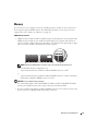
Addressing Memory Configurations
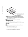
Installing Memory . . . . . . . . . .
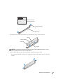
Removing Memory . . . . . . . . .
Cards
. . . . . . . . . . . . . . . . . .
. . . . . . . . . . . . . . . . . . . . . . . . .
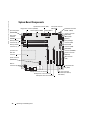
System Board Components.
Memory .
. . . . . . . . . . . . . . . . . .
. . . . . . . . . . . . . . . . . . . . . . . . . .
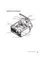
Inside View of Your Computer .
. . . . . . . . . . . . . . . . . . . .
. . . . . . . . . . . . . . . . . . . .
. . . .
84
86
89
91
94
. . . . . . . . . . . . . . . . . . . . . . . . . . . . . . . . . . . . . .
95
Removing a PCI Express Graphics Card from a Dual Configuration
Installing PCI Express Graphics Cards in a Dual Configuration . .
Removing PCI and PCI Express Cards . . . . . . . . . . . . . . .
Installing PCI and PCI Express Cards . . . . . . . . . . . . . . . .
Network Adapter and Sound Card Settings . . . . . . . . . . . .
Drives .
Hard Drive
. . . .
. . . .
95
96
. . . . . . . . . . . . . . . . . . . . . . . . . . . . . . . . . . . .
97
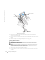
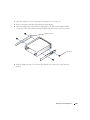
Removing a Hard Drive
Installing a Hard Drive
Floppy Drive
. . . . . . . . . . . . . . . . . . . . . .
. . . . . . . . . . . . . . . . . . . . . . . . . . .
. . . . . . . . . . . . . . . . . . . . . . . . . . .
. . . . . . . . . . . . . . . . . . . . . . . . . . . . . . . . . .
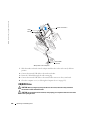
Removing a Floppy Drive
Installing a Floppy Drive
Media Card Reader
97
98
101
. . . . . . . . . . . . . . . . . . . . . . . . .
101
103
. . . . . . . . . . . . . . . . . . . . . . . . . . . . . .
105
. . . . . . . . . . . . . . . . . . . . . . . . .
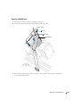
Removing a Media Card Reader
Installing a Media Card Reader .
Contents
. . . .
. . . .
. . . . . . . . . . . . . . . . . . . . . .
General Installation Guidelines .
Connecting Drive Cables . . . .
6
69
. . . . . . . . . . . . . . . . . . . . .
. . . . . . . . . . . . . . . . . . . . .
105
106
CD/DVD Drive.
. . . . . . . . . . . . . . . . . . . . . . . . . . . . . . . . .
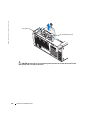
Processor Airflow Shroud .
. . . . . . . . . . . . . . . . . . . . . . . .
. . . . . . . . . . . . . . . . . . . . . . . . . .
112
. . . . . . . . . . . . . . . . . . . . . . . .
. . . . . . . . . . . . . . . .
112
113
. . . . . . . . . . . . . . . . . . . . . . . . . . . . . . . . . . .
113
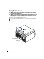
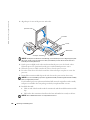
Removing the Processor Airflow Shroud .
Installing the Processor Airflow Shroud .
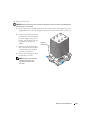
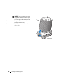
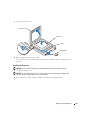
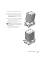
Processor .
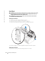
Front Panel .
. . . . . . . . . . . . . . . . . . . . . . . . .
. . . . . . . . . . . . . . . . . . . . . . . . . . . . . . . . . .
120
. . . . . . . . . . . . . . . . . . . . . . . . .
. . . . . . . . . . . . . . . . . . . . . . . .
120
120
. . . . . . . . . . . . . . . . . . . . . . . . . . . . . . . . . . .
121
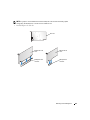
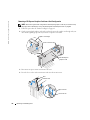
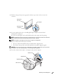
Removing the Front Panel.
Replacing the Front Panel
. . . . . . . . . . . . . . . . . . . . . . . .
. . . . . . . . . . . . . . . . . . . . . . . . . . . . . . . . . . . . .
124
Replacing the Battery .
. . . . . . . . . . . . . . . . . . . . . . . .
. . . . . . . . . . . . . . . . . . . . . . . . . .
Closing the Computer Cover .
6
. . . . . . . . . . . . . . . . . . . . . . . .
121
122
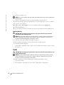
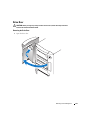
Removing the Drive Door .
Replacing the Drive Door .
Battery
. . . . . . . . . . . . . . . .
113
117
Removing the Processor
Installing the Processor
Drive Door
108
109
110
Removing a CD/DVD Drive
Installing a CD/DVD Drive .
124
. . . . . . . . . . . . . . . . . . . . . . . . .
125
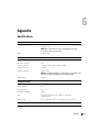
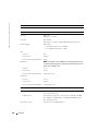
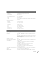
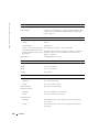
Specifications
. . . . . . . . . . . . . . . . . . . . . . . . . . . . . . . . .
127
System Setup .
. . . . . . . . . . . . . . . . . . . . . . . . . . . . . . . . .
131
Appendix
Overview . . . . . . .
Entering System Setup
System Setup Options .
Boot Sequence . . . .
. . . . . . . . . . . . . . . . . . . . . . . . . .
. . . . . . . . . . . . . . . . . . . . . . . . . .
. . . . . . . . . . . . . . . . . . . . . . . . . .
. . . . . . . . . . . . . . . . . . . . . . . . . .
131
131
132
136
. . . . . . . . . . . . . . . . . . . . . . . .
137
Clearing CMOS Settings .
. . . . . . . . . . . . . . . . . . . . . . . . . . .
138
Cleaning Your Computer .
. . . . . . . . . . . . . . . . . . . . . . . . . . .
139
Clearing Forgotten Passwords.
Computer, Keyboard, and Monitor
Mouse . . . . . . . . . . . . . . .
Floppy Drive . . . . . . . . . . . .
CDs and DVDs . . . . . . . . . . .
. . . . . . . . . . . . . . . . . . . .
. . . . . . . . . . . . . . . . . . . .
. . . . . . . . . . . . . . . . . . . .
. . . . . . . . . . . . . . . . . . . .
139
139
139
140
Contents
7
Dell Technical Support Policy (U.S. Only) .
. . . . . . . . . . . . . . . . . .
FCC Notices (U.S. Only)
. . . . . . . . .
. . . . . . . . . . . . . . . . . . . . . . . . . . . .
141
. . . . . . . . . . . . . . . . . . . . . .
. . . . . . . . . . . . . . . . . . . . . . . . . . . . . . . .
142
. . . . . . . . . . . . . . . . . . . . . . . . . . . . . . . . . . . . . . .
161
Contacting Dell .
8
Contents
. . . . . . . . .
141
142
142
Class A . . . . . . . . . . . .
Class B . . . . . . . . . . . .
FCC Identification Information
Index .
140
140
141
Definition of "Dell-Installed" Software and Peripherals
Definition of "Third-Party" Software and Peripherals. .
. . . . . . . . . . . . . . . . . . . . . .
. . . . . . . . . . . . . . . . . . . . . .
Finding Information
NOTE: Some features or media may be optional and may not ship with your computer. Some features or
media may not be available in certain countries.
NOTE: Additional information may ship with your computer.
What Are You Looking For?
Find It Here
•
•
•
•
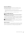
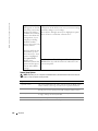
Drivers and Utilities CD (also known as ResourceCD)
A diagnostic program for my computer
Drivers for my computer
My device documentation
Desktop System Software (DSS)
Documentation and drivers are already installed on your
computer. You can use the CD to reinstall drivers or to run
the Dell Diagnostics.
Readme files may be
included on your CD to
provide last-minute
updates about technical
changes to your computer
or advanced technicalreference material for
technicians or experienced
users.
NOTE: Drivers and documentation updates can be found at
support.dell.com.
NOTE: The Drivers and Utilities CD is optional and may not
ship with your computer.
•
•
•
•
•
•
•
•
•
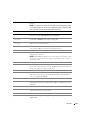
How to set up my computer
Basic troubleshooting information
How to run the Dell Diagnostics
How to set up a printer
Additional information about setting up my computer
How to troubleshoot and solve problems
How to remove and install parts
Specifications
How to contact Dell
Owner’s Manual
NOTE: This document is available as a PDF at
support.dell.com.
Finding Information
9
www.dell.com | support.dell.com
What Are You Looking For?
Find It Here
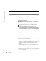
•
•
•
•
•
•
Dell™ Product Information Guide
Warranty information
Terms and Conditions (U.S. and Canada)
Safety instructions
Regulatory information
Ergonomics information
End User License Agreement
• How to set up my computer
10
Finding Information
Setup Diagram
What Are You Looking For?
Find It Here
• Service Tag and Express Service Code
• Microsoft Windows License Label
Service Tag and Microsoft® Windows® License
These labels are located on your computer.
• Use the Service Tag to
identify your computer
when you use
support.dell.com or
contact technical
support.
• Enter the Express
Service Code to direct
your call when
contacting technical
support.
Finding Information
11
www.dell.com | support.dell.com
What Are You Looking For?
Find It Here
• Solutions — Troubleshooting hints and tips, articles
from technicians, online courses, and frequently asked
questions
• Community — Online discussion with other Dell
customers
• Upgrades — Upgrade information for components, such
as memory, the hard drive, and the operating system
• Customer Care — Contact information, service call and
order status, warranty, and repair information
• Service and support — Service call status and support
history, service contract, and online discussions with
technical support
• Reference — Computer documentation, details on my
computer configuration, product specifications, and
white papers
• Downloads — Certified drivers, patches, and software
updates
• Desktop System Software (DSS)— If you reinstall the
operating system for your computer, you should also
reinstall the DSS utility. DSS provides critical updates
for your operating system and support for Dell 3.5-inch
USB floppy drives, Intel® Pentium® M processors,
optical drives, and USB devices. DSS is necessary for
correct operation of your Dell computer. The software
automatically detects your computer and operating
system and installs the updates appropriate for your
configuration.
To download Desktop System Software:
1 Go to support.dell.com and click Downloads.
2 Enter your Service Tag or product model.
3 In the Download Category drop-down menu, click All.
4 Select the operating system and operating system
language for your computer, and click Submit.
Under Select a Device, scroll to System and
Configuration Utilities, then click Dell Desktop
System Software.
Dell™ Support Website — support.dell.com
NOTE: Select your region to view the appropriate support
site.
NOTE: Corporate, government, and education customers
can also use the customized Dell Premier Support website at
premier.support. dell.com.
• How to use Windows XP
Windows Help and Support Center
1 Click the Start button, then click Help and Support.
2 Type a word or phrase that describes your problem and
click the arrow icon.
3 Click the topic that describes your problem.
4 Follow the instructions on the screen.
12
Finding Information
What Are You Looking For?
Find It Here
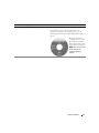
• How to reinstall my operating system
Operating System CD
The operating system is already installed on your
computer. To reinstall your operating system, use the
Operating System CD. See "Reinstalling Windows XP" on
page 65.
After you reinstall your
operating system, use the
ResourceCD to reinstall
drivers for the devices that
came with your computer.
NOTE: The color of your CD
varies based on the
operating system you
ordered.
Finding Information
13
14
Finding Information
www.dell.com | support.dell.com
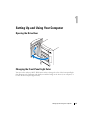
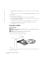
Setting Up and Using Your Computer
Opening the Drive Door
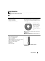
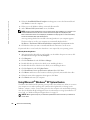
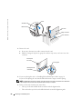
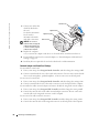
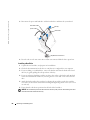
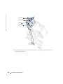
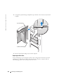
Changing the Front-Panel Light Color
You can use this exclusive Dell™ XPS feature either to change the color of the front-panel light
that illuminates the Dell name and displays around the badge on the front of your computer, or
to turn off the front-panel light entirely.
Setting Up and Using Your Computer
15
www.dell.com | support.dell.com
You can choose from several color choices:
•Off
•Ruby
•Emerald
•Sapphire (default)
•Amber
•Amethyst
front-panel
light
•Topaz
•Diamond
badge
CAUTION: Before you begin any of the procedures in this section, follow the safety instructions
located in the Product Information Guide.
NOTE: The front-panel light is not for diagnostic purposes.
1 Follow the procedures in "Before You Begin" on page 69.
2 Turn on (or restart) your computer.
3 Enter system setup by pressing <F2>. (See "Entering System Setup" on page 131 for details
about entering system setup).
4 Select the Onboard Devices option.
5 Select Front LED Color, and press <Enter>.
6 Press the left- and right- arrow keys to scroll through the color options. The front-panel light
color changes as you scroll through the options.
7 Select the color you want, and press <Enter>.
8 Press <Esc>, and press Save and Exit to save the new front-panel light color setting.
16
Setting Up and Using Your Computer
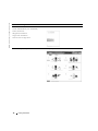
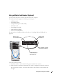
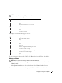
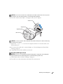
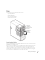
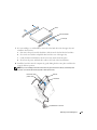
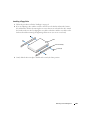
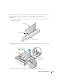
Using a Media Card Reader (Optional)
Use the media card reader to transfer data directly to your computer.
The media card reader supports the following memory types:
•
xD-Picture card
•
SmartMedia (SMC)
•
CompactFlash Type I and II (CF I/II)
•
MicroDrive card
•
SecureDigital card (SD)
•
MultiMediaCard (MMC)
•
Memory Stick (MS/MS Pro)
For information on installing a media card reader, see "Installing a Media Card Reader" on
page 106.
xD-Picture card
and SmartMedia (SMC)
Memory Stick
(MS/MS Pro)
SecureDigital card (SD)/
MultiMediaCard (MMC)
CompactFlash Type I
and II (CF I/II) and
MicroDrive card
To use the media card reader:
1 Check the media or card to determine the proper orientation for insertion.
2 Slide the media or card into the appropriate slot until it is completely seated in the connector.
If you encounter resistance, do not force the media or card. Check the card orientation and
try again.
Setting Up and Using Your Computer
17
www.dell.com | support.dell.com
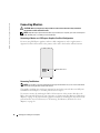
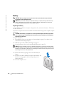
Connecting Monitors
CAUTION: Before you begin any of the procedures in this section, follow the safety instructions
located in the Product Information Guide.
NOTE: Dependent upon options selected when you purchased your computer, your video card may have
either two DVI ports or one DVI port and one VGA port.
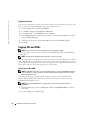
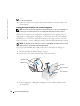
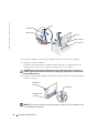
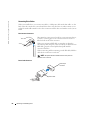
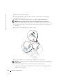
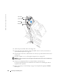
Connecting a Monitor to a PCI Express Graphics Card Dual Configuration
If you are using PCI Express graphics cards in a dual configuration, only a single monitor is
supported. Connect the monitor to the primary video card or the monitor will not function.
primary video card
Connecting Two Monitors
NOTE: Your graphics card and configuration must support dual monitors for you to connect and enable
two monitors using the instructions in this section.
The graphics card that came with your computer has an S-video port and either two DVI ports
and a DVI-to-VGA adapter, or one DVI port and one VGA port.
To connect a monitor by attaching the DVI or VGA connector of the monitor directly to the
DVI or the (optional) VGA port on your computer, see "Connecting Two Monitors (Without an
Adapter)" on page 19. If you purchased a graphics card that has two DVI ports instead of a VGA
port and need to use a VGA monitor, see "Connecting Two Monitors (With the Use of an
Adapter)" on page 20.
18
Setting Up and Using Your Computer
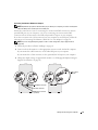
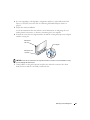
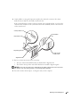
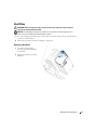
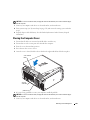
Connecting Two Monitors (Without an Adapter)
NOTE: Dependent upon options selected when you purchased your computer, your video card may have
either two DVI ports or one DVI port and one VGA port.
Follow these instructions if you are connecting two monitors with DVI connectors to the two
optional DVI ports on your computer, or if you are connecting one monitor with a DVI
connector and one VGA monitor to the DVI and optional VGA ports on your computer.
If you have a monitor with a VGA connector, but your computer has two DVI ports, follow the
instructions in "Connecting Two Monitors (With the Use of an Adapter)" on page 20.
NOTE: If you are using PCI Express graphics cards in a dual configuration, only a single monitor is
supported.
1 Follow the procedures in "Before You Begin" on page 69.
2 Connect each of the monitors to a the appropriate connector on the back of the computer.
If your monitor has a DVI connector, use the white DVI port on your computer.
If your monitor has a VGA connector, use the (optional) blue VGA port on your computer.
3 Change the display settings to support both monitors (see "Changing the Display Settings to
Support Two Monitors" on page 20).
DVI-to-VGA
adapter
DVI (white) connector
TV-OUT connector
VGA (blue) connector
(optional)
Setting Up and Using Your Computer
19
www.dell.com | support.dell.com
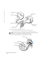
Connecting Two Monitors (With the Use of an Adapter)
Follow these instructions if you purchased a graphics card that has two DVI ports instead of a
VGA port and need to use a VGA monitor.
NOTE: If you are using PCI Express graphics cards in a dual configuration, only a single monitor is
supported.
1 Follow the procedures in "Before You Begin" on page 69.
2 Attach the DVI connector on the appropriate monitor to the white DVI port on the back of
the computer.
NOTE: Your graphics card must support a VGA monitor being connected to the DVI port.
3 Connect the DVI-to-VGA adapter to the VGA connector on the other monitor, then connect
the adapter to the white DVI port on the back of the computer.
4 Change the display settings to support both monitors (see "Changing the Display Settings to
Support Two Monitors" on page 20).
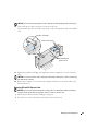
Connecting a TV
NOTE: If you are connecting a TV, you may connect only one monitor (VGA or DVI) in addition to the TV.
NOTE: See the documentation that came with your TV to ensure that you properly configure and connect
the TV.
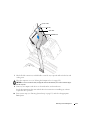
To connect a TV to your computer, you must purchase an S-video cable, which is available at
most consumer electronics stores. An S-video cable is not included with your computer.
1 Follow the procedures in "Before You Begin" on page 69.
2 Connect one end of the S-video cable to the TV-OUT connector on the back of the computer.
3 Connect the other end of the S-video cable to the S-video input connector on your TV.
4 Connect one VGA or DVI monitor as described in the preceding subsection, "Connecting
Two Monitors (Without an Adapter)" on page 19.
Changing the Display Settings to Support Two Monitors
1 After you connect the monitors, turn on the computer.
The Microsoft® Windows® desktop displays on the primary monitor.
2 Enable clone mode or extended desktop mode in the display settings.
•
In clone mode, both monitors display the same image.
•
In extended desktop mode, you can drag objects from one screen to the other, effectively
doubling the amount of viewable work space.
For information on changing the display settings for your graphics card, see the user’s guide in
the Help and Support Center (click the Start button, click Help and Support, click User and
system guides, click Device guides, and then click the guide for your graphics card).
20
Setting Up and Using Your Computer
About Serial ATA Drives
Your computer supports up to three serial ATA hard drives. Serial ATA drives provide the
following benefits by transferring data using serial technology and flexible cables that are
thinner and longer than IDE cables:
•
Improved cable routing facilitates more efficient airflow inside the chassis.
•
Compact cable connectors save space on the system board and on the hard drive. Combined
with the improved cable routing, this allows a more efficient utilization of space inside the
chassis.
See "Hard Drive" on page 97 for information on serial ATA drive connections.
About Your RAID Configuration
NOTICE: If you might ever decide to migrate to a RAID array, before loading the operating system onto a
hard drive, set up that drive as a single drive RAID 0 array. See "Creating an Array using the Nvidia
MediaShield ROM Utility" on page 23 for instructions.
This section provides an overview of the RAID configuration that you might have selected when
you purchased your computer. Dell offers either a RAID level 0 configuration or a RAID level 1
configuration on your Dell™ XPS computer. A RAID level 0 configuration is recommended for
high-performance gaming, and a RAID level 1 configuration is recommended for the data
integrity requirements of digital photography and audio.
NOTE: RAID levels do not represent a hierarchy. A RAID level 1 configuration is not inherently better or
worse than a RAID level 0 configuration.
The drives in an array should be the same size in order to ensure that the larger drive does not
contain unallocated (and therefore unusable) space.
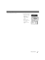
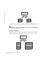
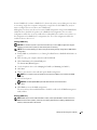
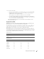
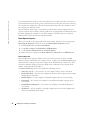
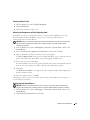
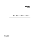
RAID Level 0 Configuration
A RAID level 0 configuration uses a storage technique known as "data striping" to provide a high
data access rate. Data striping is a method of writing consecutive segments, or stripes, of data
sequentially across the physical drives to create a large virtual drive. Data striping allows one of
the drives to read data while the other drive is searching for and reading the next block.
Setting Up and Using Your Computer
21
www.dell.com | support.dell.com
serial ATA RAID
configured for
RAID level 0
segment 1
segment 2
segment 3
segment 4
segment 5
segment 6
hard drive 1
hard drive 2
Another advantage of a RAID level 0 configuration is that it utilizes the full capacities of the
drives. For example, if you have two 120-GB drives installed, you have 240 GB on which to store
data.
NOTICE: Because RAID level 0 configurations provide no data redundancy, if one drive fails, then the
data on the other drive is also inaccessible. Therefore, ensure that you perform regular backups when
you use a RAID level 0 configuration.
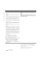
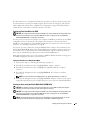
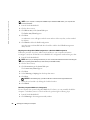
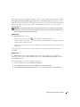
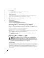
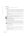
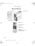
RAID Level 1 Configuration
RAID level 1 uses a data-redundancy storage technique known as "mirroring." When data is
written to the primary drive, it is then duplicated, or mirrored, on the other drive. A RAID
level 1 configuration sacrifices high data-access rates for its data redundancy advantages.
serial ATA RAID
configured for
RAID level 1
segment 1
segment 1 duplicated
segment 2
segment 2 duplicated
segment 3
segment 3 duplicated
segment 4
segment 4 duplicated
segment 5
segment 5 duplicated
segment 6
segment 6 duplicated
hard drive 1
22
Setting Up and Using Your Computer
hard drive 2
If a drive failure occurs, subsequent read and write operations are directed to the surviving drive.
A replacement drive can then be rebuilt using the data from the surviving drive. Also, because
data is duplicated on both drives, a RAID level 1 configuration using two 120-GB hard drives
collectively has a maximum of 120 GB on which to store data.
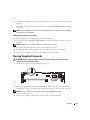
Configuring Your Hard Drives for RAID
NOTICE: If you might ever decide to migrate to a RAID array, before loading the operating system onto a
hard drive, set up that drive as a single drive RAID 0 array. See "Creating an Array using the Nvidia
MediaShield ROM Utility" on page 23 for instructions.
At some point you may want to configure your computer for RAID if you did not select a RAID
configuration when you purchased your computer. You must have at least two hard drives
installed in your computer to set up a RAID configuration. For instructions on how to install a
hard drive, see "Installing a Hard Drive" on page 98.
You can use one of two methods to configure RAID hard drive volumes. One method uses the
Nvidia MediaShield ROM utility and is performed before you install the operating system onto
the hard drive. The second method uses Nvidia MediaShield, and this method is performed
after you have installed the operating system with the Nvidia RAID drivers.
Both methods require that you set your computer to RAID-enabled mode before starting any of
the RAID configuration procedures in this document.
Setting Your Hard Drives to RAID-Enabled Mode
1 Enter system setup (see "Entering System Setup" on page 131).
2 Press the up- and down-arrow keys to highlight Drives, and press <Enter>.
3 Press the up- and down-arrow keys to highlight the applicable SATA drive, and press
<Enter>.
4 Press the left- and right-arrow keys to highlight RAID On, press <Enter>, and then
press <Esc>.
NOTE: For more information about RAID options, see "System Setup Options" on page 132.
5 Press the left- and right-arrow keys to highlight Save/Exit, and press <Enter> to exit system
setup and resume the boot process. Repeat the process as necessary for each SATA hard drive.
Creating an Array using the Nvidia MediaShield ROM Utility
NOTICE: You will lose any data on your hard drives when you create a RAID configuration using the
following procedure. Back up data you want to keep before continuing.
NOTICE: If you might ever decide to migrate to a RAID array, before loading the operating system onto a
hard drive, set up that drive as a single drive RAID 0 array. See "Creating an Array using the Nvidia
MediaShield ROM Utility" on page 23 for instructions.
NOTE: Use the following procedure only if you are reinstalling your operating system. Do not use the
following procedure to migrate an existing storage configuration to a RAID configuration.
Setting Up and Using Your Computer
23
www.dell.com | support.dell.com
Although any size drives may be used to create a RAID configuration, ideally the drives should
be of equal size. In a RAID level 0 configuration, the size of the configuration will be the size of
the smaller drive multiplied by the number (two) of drives in the configuration. In a RAID level
1 configuration, the size of the configuration will be the smaller of the two drives used.
1 Enable RAID on your hard drives (see "Setting Your Hard Drives to RAID-Enabled Mode" on
page 23).
2 Press <Ctrl-n> when prompted to enter the RAID BIOS.
NOTICE: If you do not press <Ctrl-n> before the window closes, restart your computer and wait for
the prompt to appear again.
The Define a New Array window appears.
3 Press <Tab> to navigate to the RAID Mode field.
To create a RAID 0 configuration, use the arrow keys to select Striping.
To create a RAID 1 configuration, use the arrow keys to select Mirroring.
4 Press <Tab> to navigate to the Free Disks field.
5 Use the right- and left-arrow keys to select the hard drive or drives to include in your RAID
array; move the listed hard drives from the Free Disks field to the Array Disks field.
NOTE: Your computer supports a maximum of two drives per RAID1 array and three per RAID0
array.
6 After assigning hard drives to an array, press <F9>.
NOTICE: You will lose all data on the selected drives in the next step.
7 Press <Y> to clear all data from the selected drives.
The Array Detail window appears.
8 To specify the array as bootable, use the arrow keys to select the array and press <B>.
9 To review the details of the array that you set up, use the arrow keys to highlight the array in
the Array Detail window and press <Enter>.
To delete an array, navigate to the array using the arrow keys and press <D>.
Press <Enter> to return to the previous screen.
10 Press <Ctrl><X> to exit the RAID BIOS.
Using Nvidia MediaShield
Nvidia MediaShield allows you to create, view, and manage RAID configurations. If you already
have one hard drive with the operating system installed on it, and you want to add a second hard
drive and reconfigure both drives into a RAID volume without losing the existing operating
system and any data, you need to use the morphing option (see "Morphing from a Single Drive
RAID 0 Configuration to a Dual Drive RAID Configuration" on page 26).
24
Setting Up and Using Your Computer
Create a RAID level 0 volume or RAID level 1 volume only when you are adding two new drives
to an existing single-drive computer configured as a single-drive level 0 RAID array, and you
want to configure the two new drives into a RAID array.
Although any size drives may be used to create a RAID configuration using Nvidia MediaShield,
ideally the drives should be of equal size. In a RAID level 0 configuration, the size of the
configuration will be the size of the smallest drive multiplied by the number (two) of drives in
the configuration. In a RAID level 1 configuration, the size of the configuration will be the
smaller of the two drives used.
Creating a RAID Array
NOTICE: You will lose any data on your hard drives when you create a RAID configuration using the
following procedure. Back up data you want to keep before continuing.
NOTE: Do not use the following procedure to migrate an existing storage configuration to RAID level 0
configuration.
1 Enable RAID on your hard drives (see "Setting Your Hard Drives to RAID-Enabled Mode" on
page 23).
2 After rebooting your computer, launch Nvidia MediaShield.
3 Click Create Array in the System Tasks pane.
The Create Array Wizard appears.
4 Use the drop-down box to select Striping (for RAID 0) or Mirroring (for RAID 1).
5 Click Next.
6 Click to select the drives that will make up the RAID configuration.
NOTE: Your computer supports a maximum of two drives per RAID1 array and three per RAID0
array.
7 Select desired options.
NOTICE: The Clear System Data option will delete all data on the selected drive.
8 Click Next.
9 Click Finish to create the RAID configuration.
The array and any other installed hard drives should be visible in the NVRAID management
utility window.
Deleting a RAID Array
NOTE: While this procedure deletes the RAID 1 volume, it also splits the RAID 1 volume into two nonRAID hard drives with a partition, and leaves any existing data files intact. Deleting a RAID 0 volume,
however, destroys all data on the volume.
Setting Up and Using Your Computer
25
www.dell.com | support.dell.com
NOTE: If your computer currently boots to RAID and you delete the RAID volume, your computer will
become unbootable.
1 Launch Nvidia MediaShield.
2 Click to select an array.
3 Click Delete Array in the System Tasks pane.
The Delete Array Wizard appears.
4 Click Next.
A confirmation screen will appear with the name and size of the array that you have marked
for deletion.
5 Click Finish to delete the RAID configuration.
Any other arrays and installed hard drives should be visible in the NVRAID management
utility window.
Morphing from a Single Drive RAID 0 Configuration to a Dual Drive RAID Configuration
Follow this procedure if you have added a new hard drive to your computer and want to
reconfigure it and your old hard drive into a RAID level 1 configuration without losing any data.
1 Launch Nvidia MediaShield.
NOTE: Select your pre-existing hard drive as your source drive (it should be the hard drive containing the
data or operating system files that you want to keep on the RAID volume).
2 Click to select an array.
3 Click Convert Array in the System Tasks pane.
The Convert Array Wizard appears.
4 Click Next.
5 Select Mirroring or Striping from the drop-down menu.
6 Click Next.
NOTICE: In the following step, you will lose all data contained on the target member drive.
7 Select the new hard drive by clicking the checkbox beside it.
8 Click Finish.
Rebuilding a Degraded RAID Level 1 Configuration
If your computer has reported a degraded RAID level 1 volume, you can manually rebuild the
computer’s redundancy mirror to a new hard drive by performing the following steps:
1 Launch Nvidia MediaShield.
2 Click Mirroring in the management utility window.
26
Setting Up and Using Your Computer
3 Select Rebuild Array in the System Tasks pane.
The Rebuild Array Wizard appears.
4 Click Next.
5 Click to select the hard drive that you want to rebuild.
6 Click Finish.
You can use your computer while the computer is rebuilding the RAID level 1 volume.
Transferring Information to a New Computer
The Microsoft® Windows® XP operating system provides a Files and Settings Transfer wizard to
move data from the source computer to the new computer. You can move data such as:
•
E-mails
•
Toolbar settings
•
Window sizes
•
Internet bookmarks
You can transfer the data to the new computer over a network or serial connection, or you can
store it on a removable medium, such as a writable CD or floppy disk.
To prepare the new computer for the file transfer:
1 Click the Start button, point to All Programs→ Accessories→ System Tools, and then click
Files and Settings Transfer Wizard.
2 When the Files and Settings Transfer Wizard welcome screen appears, click Next.
3 On the Which computer is this? screen, click New Computer and click Next.
4 On the Do you have a Windows XP CD? screen, click I will use the wizard from the
Windows XP CD and click Next.
5 When the Now go to your old computer screen appears, go to your old or source computer.
Do not click Next at this time.
To copy data from the old computer:
1 On the old computer, insert the Windows XP Operating System CD.
2 On the Welcome to Microsoft Windows XP screen, click Perform additional tasks.
3 Under What do you want to do?, click Transfer files and settings.
4 On the Files and Settings Transfer Wizard welcome screen, click Next.
5 On the Which computer is this? screen, click Old Computer and click Next.
6 On the Select a transfer method screen, click the transfer method you prefer.
Setting Up and Using Your Computer
27
www.dell.com | support.dell.com
7 On the What do you want to transfer? screen, select the items you want to transfer and click
Next.
After the information has been copied, the Completing the Collection Phase screen appears.
8 Click Finish.
To transfer data to the new computer:
1 On the Now go to your old computer screen on the new computer, click Next.
2 On the Where are the files and settings? screen, select the method you chose for transferring
your settings and files and click Next.
The wizard reads the collected files and settings and applies them to your new computer.
When all of the settings and files have been applied, the Finished screen appears.
3 Click Finished and restart the new computer.
Playing CDs and DVDs
Playing a CD or DVD
NOTICE: Do not press down on the CD or DVD tray when you open or close it. Keep the tray closed when
you are not using the drive.
NOTICE: Do not move the computer when you are playing CDs or DVDs.
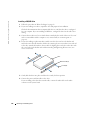
1 Press the eject button on the front of the drive.
2 Place the disc, label side up, in the center of the tray.
3 Press the eject button or gently push in the tray.
To format CDs for storing data, to create music CDs, or to copy CDs, see the CD software that
came with your computer.
28
Setting Up and Using Your Computer
NOTE: Ensure that you follow all copyright laws when you create CDs.
A CD player includes the following basic buttons:
Play
Move backward within the current track
Pause
Move forward within the current track
Stop
Go to the previous track
Eject
Go to the next track
A DVD player includes the following basic buttons:
Stop
Restart the current chapter
Play
Fast forward
Pause
Fast reverse
Advance a single frame while in pause mode
Go to the next title or chapter
Continuously play the current title or chapter
Go to the previous title or chapter
Eject
For more information on playing CDs or DVDs, click Help on the CD or DVD player (if available).
Adjusting the Volume
NOTE: When the speakers are muted, you do not hear the CD or DVD playing.
1 Click the Start button, point to All Programs→ Accessories→ Entertainment, and then click
Volume Control.
2 In the Volume Control window, click and drag the bar in the Volume Control column and
slide it up or down to increase or decrease the volume.
For more information on volume control options, click Help in the Volume Control window.
Setting Up and Using Your Computer
29
www.dell.com | support.dell.com
Adjusting the Picture
If an error message notifies you that the current resolution and color depth are using too much
memory and preventing DVD playback, adjust the display properties.
1 Click the Start button and click Control Panel.
2 Under Pick a category, click Appearance and Themes.
3 Under Pick a task..., click Change the screen resolution.
4 In the Display Properties window, click and drag the bar in Screen resolution to change the
setting to 800 by 600 pixels.
5 Click the drop-down menu under Color quality, and then click Medium (16 bit).
6 Click OK.
Copying CDs and DVDs
NOTE: Ensure that you observe all copyright laws when creating CDs or DVDs.
This section applies only to computers that have a CD-RW, DVD+/-RW, or CD-RW/DVD
(combo) drive.
NOTE: The types of CD or DVD drives offered by Dell™ may vary by country.
The following instructions explain how to make an exact copy of a CD or DVD. You can also use
Sonic DigitalMedia for other purposes, such as creating music CDs from audio files stored on
your computer or backing up important data. For help, open Sonic DigitalMedia and then click
the question mark icon in the upper-right corner of the window.
How to Copy a CD or DVD
NOTE: CD-RW/DVD combo drives cannot write to DVD media. If you have a CD-RW/DVD combo drive
and you experience recording problems, check for available software patches on the Sonic support
website at www.sonic.com.
The DVD-writable drives installed in Dell computers can write to and read DVD+/-R,
DVD+/-RW and DVD+R DL (dual layer) media, but cannot write to and may not read
DVD-RAM or DVD-R DL media.
NOTE: Most commercial DVDs have copyright protection and cannot be copied using Sonic
DigitalMedia.
1 Click the Start button, point to All Programs→ Sonic→ DigitalMedia Projects, and then
click Copy.
2 Under the Copy tab, click Disc Copy.
30
Setting Up and Using Your Computer
3 To copy the CD or DVD:
•
If you have one CD or DVD drive, ensure that the settings are correct and click the Disc
Copy button. The computer reads your source CD or DVD and copies the data to a
temporary folder on your computer hard drive.
When prompted, insert a blank CD or DVD into the drive and click OK.
•
If you have two CD or DVD drives, select the drive into which you have inserted your
source CD or DVD and click the Disc Copy button. The computer copies the data from
the source CD or DVD to the blank CD or DVD.
Once you have finished copying the source CD or DVD, the CD or DVD that you have
created automatically ejects.
Using Blank CDs and DVDs
CD-RW drives can write to CD recording media only (including high-speed CD-RW) while
DVD-writable drives can write to both CD and DVD recording media.
Use blank CD-Rs to record music or permanently store data files. After creating a CD-R, you
cannot write to that CD-R again (see the Sonic documentation for more information). Use
blank CD-RWs to write to CDs or to erase, rewrite, or update data on CDs.
Blank DVD+/-Rs can be used to permanently store large amounts of information. After you
create a DVD+/-R disc, you may not be able to write to that disc again if the disc is "finalized" or
"closed" during the final stage of the disc creation process. Use blank DVD+/-RWs if you plan
to erase, rewrite, or update information on that disc later.
CD-Writable Drives
Media Type
Read
Write
Rewritable
CD-R
Yes
Yes
No
CD-RW
Yes
Yes
Yes
Media Type
Read
Write
Rewritable
CD-R
Yes
Yes
No
CD-RW
Yes
Yes
Yes
DVD+R
Yes
Yes
No
DVD-R
Yes
Yes
No
DVD+RW
Yes
Yes
Yes
DVD-RW
Yes
Yes
Yes
DVD+R DL
Yes
Yes
No
DVD-Writable Drives
Setting Up and Using Your Computer
31
www.dell.com | support.dell.com
Media Type
Read
Write
Rewritable
DVD-R DL
Maybe
No
No
DVD-RAM
Maybe
No
No
Helpful Tips
•
Use Microsoft® Windows® Explorer to drag and drop files to a CD-R or CD-RW only after
you start Sonic DigitalMedia and open a DigitalMedia project.
•
Use CD-Rs to burn music CDs that you want to play in regular stereos. CD-RWs do not play
in most home or car stereos.
•
You cannot create audio DVDs with Sonic DigitalMedia.
•
Music MP3 files can be played only on MP3 players or on computers that have MP3 software
installed.
•
Commercially available DVD players used in home theater systems may not support all
available DVD formats. For a list of formats supported by your DVD player, see the
documentation provided with your DVD player or contact the manufacturer.
•
Do not burn a blank CD-R or CD-RW to its maximum capacity; for example, do not copy a
650-MB file to a blank 650-MB CD. The CD-RW drive needs 1–2 MB of the blank space to
finalize the recording.
•
Use a blank CD-RW to practice CD recording until you are familiar with CD recording
techniques. If you make a mistake, you can erase the data on the CD-RW and try again. You
can also use blank CD-RWs to test music file projects before you record the project
permanently to a blank CD-R.
•
See the Sonic website at www.sonic.com for additional information.
Network Setup Wizard
The Microsoft® Windows® XP operating system provides a Network Setup Wizard to guide you
through the process of sharing files, printers, or an Internet connection between computers in a
home or small office.
1 Click the Start button, point to All Programs→ Accessories→ Communications, and then
click Network Setup Wizard.
2 On the welcome screen, click Next.
3 Click Checklist for creating a network.
NOTE: Selecting the connection method This computer connects directly to the Internet enables the
integrated firewall provided with Windows XP SP1.
4 Complete the checklist and required preparations.
Return to the Network Setup Wizard and follow the instructions on the screen.
32
Setting Up and Using Your Computer
Power Management
Overview
The Microsoft® Windows® XP power management features can reduce the amount of
electricity your computer uses when it is on and you are not using it. You can reduce power to
just the monitor or the hard drive, or you can use standby mode or hibernate mode to reduce
power to the entire computer. When the computer exits from a power conservation mode, the
Windows desktop is restored to the state it was in before it entered the mode.
NOTE: Windows XP Professional includes security and networking features not available in
Windows XP Home Edition. When a Windows XP Professional computer is connected to a network,
different options related to security and networking appear in certain windows.
NOTE: Depending on your operating system, the procedures to activate the standby and hibernate
modes may be different.
Standby Mode
Standby mode conserves power by turning off the display and the hard drive after a time-out.
When the computer exits from standby mode, it returns to the operating state it was in before it
entered standby mode.
To set standby mode to automatically activate after a defined period of inactivity:
1 Click the Start button and click Control Panel.
2 Under Pick a category, click Performance and Maintenance.
3 Under or pick a Control Panel icon, click Power Options.
To immediately activate standby mode without a period of inactivity, click the Start button,
click Turn Off Computer, and then click Stand by.
To exit from standby mode, press a key on the keyboard or move the mouse.
NOTICE: If your computer loses power while in standby mode, it may lose data.
Hibernate Mode
Hibernate mode conserves power by copying system data to a reserved area on the hard drive
and then completely turning off the computer. When the computer exits from hibernate mode,
the desktop is restored to the state it was in before it entered hibernate mode.
To activate hibernate mode:
1 Click the Start button and click Control Panel.
2 Under Pick a category, click Performance and Maintenance.
3 Under or pick a Control Panel icon, click Power Options.
4 Define your hibernate settings on the Power Schemes tab, Advanced tab, and Hibernate tab.
Setting Up and Using Your Computer
33
www.dell.com | support.dell.com
To exit from hibernate mode, press the power button. The computer may take a short time to
exit from hibernate mode. Pressing a key on the keyboard or moving the mouse does not bring
the computer out of hibernation, because the keyboard and the mouse do not function when
the computer is in hibernate mode.
Because hibernate mode requires a special file on your hard drive with enough disk space to
store the contents of the computer memory, Dell creates an appropriately sized hibernate mode
file before shipping the computer to you. If the computer’s hard drive becomes corrupted,
Windows XP recreates the hibernate file automatically.
Power Options Properties
Define your standby mode settings, hibernate mode settings, and other power settings in the
Power Options Properties window. To access the Power Options Properties window:
1 Click the Start button and click Control Panel.
2 Under Pick a category, click Performance and Maintenance.
3 Under or pick a Control Panel icon, click Power Options.
4 Define your power settings on the Power Schemes tab, Advanced tab, and Hibernate tab.
Power Schemes Tab
Each standard power setting is called a scheme. If you want to select one of the standard
Windows schemes installed on your computer, choose a scheme from the Power schemes dropdown menu. The settings for each scheme appear in the fields below the scheme name. Each
scheme has different settings for starting standby mode or hibernate mode, turning off the
monitor, and turning off the hard drive.
The Power schemes drop-down menu displays the following schemes:
34
•
Always On (default) — If you want to use your computer with no power conservation.
•
Home/Office Desk — If you use your computer as a home or office computer and you require
minimal power conservation.
•
Portable/Laptop — If your computer is a portable computer that you use for traveling.
•
Presentation — If you want your computer to run without interruption (using no power
conservation).
•
Minimal Power Management — If you want your computer to run with minimal power
conservation.
•
Max Battery — If your computer is a portable computer and you run your computer from
batteries for extended periods of time.
Setting Up and Using Your Computer
If you want to change the default settings for a scheme, click the drop-down menu in the Turn
off monitor, Turn off hard disks, System stand by, or System hibernates field, and then select a
time-out from the displayed list. Changing the time-out for a scheme field permanently changes
the default settings for that scheme, unless you click Save As and enter a new name for the
changed scheme.
NOTICE: If you set the hard drive to time-out before the monitor does, your computer may appear to be
locked up. To recover, press any key on the keyboard or click the mouse. To avoid this problem, always
set the monitor to time-out before the hard drive.
Advanced Tab
The Advanced tab allows you to:
•
Place the power options icon
in the Windows taskbar for quick access.
•
Set the computer to prompt you for your Windows password before the computer exits from
standby mode or hibernate mode.
•
Program the power button to activate standby mode, activate hibernate mode, or turn off the
computer.
To program these functions, click an option from the corresponding drop-down menu and
click OK.
Hibernate Tab
The Hibernate tab allows you to enable hibernate mode. If you want to use the hibernate
settings you defined on the Power Schemes tab, click the Enable hibernate support check box
on the Hibernate tab.
For more information on power management options:
1 Click the Start button and click Help and Support.
2 In the Help and Support window, click Performance and maintenance.
3 In the Performance and maintenance window, click Conserving power on your computer.
Setting Up and Using Your Computer
35
www.dell.com | support.dell.com
36
Setting Up and Using Your Computer
Optimizing Performance
Hyper-Threading
Hyper-Threading is an Intel® technology that can enhance overall computer performance by
allowing one physical processor to function as two logical processors, capable of performing
certain tasks simultaneously. It is recommended that you use the Microsoft® Windows® XP
Service Pack 1 (SP1) or later operating system because Windows XP is optimized to take
advantage of Hyper-Threading technology. While many programs can benefit from HyperThreading, some programs have not been optimized for Hyper-Threading and may require an
update from the software manufacturer. Contact the software manufacturer for updates and
information about using Hyper-Threading with your software.
To determine if your computer is using Hyper-Threading technology:
1 Click the Start button, right-click My Computer, and then click Properties.
2 Click Hardware and click Device Manager.
3 In the Device Manager window, click the plus (+) sign next to Processors. If Hyper-Threading
is enabled, the processor is listed twice.
You can enable or disable Hyper-Threading through system setup. For more information on
accessing system setup, see "System Setup" on page 131. For more information on HyperThreading, search the Knowledge Base on the Dell website at support.dell.com.
PCI Express Cards
PCI Express is the next generation technology for graphics cards and PCI cards. The PCI
Express x16 slot is used in place of the AGP graphics card slot. The dimensions of PCI Express
card slots are different from those of the PCI card slots, and the cards are not interchangeable
(you cannot install a PCI card in a PCI Express card slot, or a PCI Express card in a PCI card
slot).
Some benefits of PCI Express technology include:
•
Greater available bandwidth — PCI Express bus bandwidth is 250 MB/s in each direction per
lane simultaneously, while PCI bus bandwidth is 133 MB/s in one direction at a time.
•
Prioritization of service — Multiple PCI cards installed in a computer all share a common
bus, but each PCI Express card operates on its own channel. Activities such as video
conferencing and web camera functions can be automatically prioritized through the device
software to reduce latency.
Optimizing Performance
37
www.dell.com | support.dell.com
NVIDIA SLI Dual Graphics Technology
With NVIDIA SLI (Scalable Link Interface) dual-graphics technology, an optional second PCI
Express graphics card will significantly increase graphics performance on your computer.
Benefits of this technology can be seen in the improved portrayal of the 3-D graphics used in
gaming and design applications.
Each graphics card includes a GPU (graphics processing unit). The two GPUs dynamically share
their workload to provide the best possible performance. For a given application, the SLI
software selects the optimum rendering (processing) mode. The two most basic modes are split
frame rendering and alternate frame rendering. In split frame rendering, the GPUs divide the
work; each GPU renders part of every frame that displays. In the alternate frame rendering
mode, each GPU alternately renders the full-screen image.
For more information, see the documentation that came with your graphics card.
38
Optimizing Performance
Solving Problems
Troubleshooting Tips
Follow these tips when you troubleshoot your computer:
•
If you added or removed a part before the problem started, review the installation procedures
and ensure that the part is correctly installed.
•
If a peripheral device does not work, ensure that the device is properly connected.
•
If an error message appears on the screen, write down the exact message. This message may
help technical support personnel diagnose and fix the problem(s).
If an error message occurs in a program, see the program’s documentation.
Battery Problems
CAUTION: There is a danger of a new battery exploding if it is incorrectly installed. Replace the
battery only with the same or equivalent type recommended by the manufacturer. Discard used
batteries according to the manufacturer's instructions.
CAUTION: Before you begin any of the procedures in this section, follow the safety instructions
located in the Product Information Guide.
R E P L A C E T H E B A T T E R Y — If you have to repeatedly reset time and date information after turning on
the computer, or if an incorrect time or date displays during start-up, replace the battery (see "Replacing
the Battery" on page 124). If the battery still does not work properly, contact Dell (see "Contacting Dell"
on page 142).
Drive Problems
CAUTION: Before you begin any of the procedures in this section, follow the safety instructions
located in the Product Information Guide.
Solving Problems
39
www.dell.com | support.dell.com
E N S U R E T H A T M I C R O S O F T ® W I N D O W S ® R E C O G N I Z E S T H E D R I V E — Click the Start button and
click My Computer. If the floppy, CD, or DVD drive, is not listed, perform a full scan with your
antivirus software to check for and remove viruses. Viruses can sometimes prevent Windows from
recognizing the drive.
TE S T T H E D R I V E —
• Insert another floppy disk, CD, or DVD to eliminate the possibility that the original one is defective.
• Insert a bootable floppy disk and restart the computer.
C L E A N T H E D R I V E O R D I S K — See "Cleaning Your Computer" on page 139.
CHECK THE CABLE CONNECTIONS
R U N T H E H A R D W A R E TR O U B L E S H O O T E R — See "Resolving Software and Hardware Incompatibilities"
on page 64.
R U N T H E D E L L D I A G N O S T I C S — See "Dell Diagnostics" on page 58.
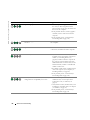
CD and DVD drive problems
NOTE: High-speed CD or DVD drive vibration is normal and may cause noise, which does not indicate a
defect in the drive or the CD or DVD.
NOTE: Because of different regions worldwide and different disc formats, not all DVD titles work in all
DVD drives.
ADJUST THE WINDOWS VOLUME CONTROL —
• Click the speaker icon in the lower-right corner of your screen.
• Ensure that the volume is turned up by clicking the slidebar and dragging it up.
• Ensure that the sound is not muted by clicking any boxes that are checked.
C H E C K T H E S P E A K E R S A N D S U B W O O F E R — See "Sound and Speaker Problems" on page 51.
40
Solving Problems
Problems writing to a CD/DVD-RW drive
C L O S E O T H E R P R O G R A M S — The CD/DVD-RW drive must receive a steady stream of data when
writing. If the stream is interrupted, an error occurs. Try closing all programs before you write to the
CD/DVD-RW.
TU R N O F F S T A N D B Y M O D E I N W I N D O W S B E F O R E W R I T I N G T O A C D / D V D - R W D I S C — See
"Standby Mode" on page 33 or search for the keyword standby in Windows Help and Support Center.
for information on power management modes. For information on accessing window Help, see
"Windows Help and Support Center" on page 12.
Hard drive problems
RUN CHECK DISK —
1 Click the Start button and click My Computer.
2 Right-click Local Disk C:.
3 Click Properties.
4 Click the Tools tab.
5 Under Error-checking, click Check Now.
6 Click Scan for and attempt recovery of bad sectors.
7 Click Start.
E-Mail, Modem, and Internet Problems
CAUTION: Before you begin any of the procedures in this section, follow the safety instructions
located in the Product Information Guide.
NOTE: Connect the modem to an analog telephone jack only. The modem does not operate while it is
connected to a digital telephone network.
C H E C K T H E M I C R O S O F T O U T L O O K ® E X P R E S S S E C U R I T Y S E T T I N G S — If you cannot open your e-mail
attachments:
1 In Outlook Express, click Tools, click Options, and then click Security.
2 Click Do not allow attachments to remove the checkmark.
Solving Problems
41
www.dell.com | support.dell.com
CHECK THE TELEPHONE LINE CONNECTION —
CHECK THE TELEPHONE JACK —
CONNECT THE MODEM DIRECTLY TO THE TELEPHONE WALL JACK —
USE A DIFFERENT TELEPHONE LINE —
• Verify that the telephone line is connected to the jack on the modem. (The jack has either a green label
or a connector-shaped icon next to it.)
• Ensure that you hear a click when you insert the telephone line connector into the modem.
• Disconnect the telephone line from the modem and connect it to a telephone. Listen for a dial tone.
• If you have other telephone devices sharing the line, such as an answering machine, fax machine, surge
protector, or line splitter, then bypass them and use the telephone to connect the modem directly to the
telephone wall jack. If you are using a line that is 3 m (10 ft) or more in length, try a shorter one.
R U N T H E M O D E M H E L P E R D I A G N O S T I C S — Click the Start button, point to All Programs, and then
click Modem Helper. Follow the instructions on the screen to identify and resolve modem problems.
(Modem Helper is not available on all computers.)
VE R I F Y T H A T T H E M O D E M I S C O M M U N I C A T I N G W I T H W I N D O W S —
1 Click the Start button and click Control Panel.
2 Click Printers and Other Hardware.
3 Click Phone and Modem Options.
4 Click the Modems tab.
5 Click the COM port for your modem.
6 Click Properties, click the Diagnostics tab, and then click Query Modem to verify that the modem is
communicating with Windows.
If all commands receive responses, the modem is operating properly.
E N S U R E T H A T Y O U A R E C O N N E C T E D T O T H E I N T E R N E T — Ensure that you have subscribed to an
Internet provider. With the Outlook Express e-mail program open, click File. If Work Offline has a
checkmark next to it, click the checkmark to remove it and connect to the Internet. For help, contact
your Internet service provider.
Error Messages
CAUTION: Before you begin any of the procedures in this section, follow the safety instructions
located in the Product Information Guide.
If the message is not listed, see the documentation for the operating system or the program that
was running when the message appeared.
42
Solving Problems
A F I L E N A M E C A N N O T C O N T A I N A N Y O F T H E F O L L O W I N G C H A R A C T E R S : \ / : * ? “ < > | — Do not
use these characters in filenames.
A R E Q U I R E D . D L L F I L E W A S N O T F O U N D — The program that you are trying to open is missing an
essential file. To remove and then reinstall the program:
1 Click the Start button, click Control Panel, and then click Add or Remove Programs.
2 Select the program you want to remove.
3 Click the Change or Remove Program icon.
4 See the program documentation for installation instructions.
drive letter : \ I S N O T A C C E S S I B L E . T H E D E V I C E I S N O T R E A D Y — The drive cannot read the disk.
Insert a disk into the drive and try again.
I N S E R T B O O T A B L E M E D I A — Insert a bootable floppy disk or CD.
N O N - S YS T E M D I S K E R R O R — Remove the floppy disk from the drive and restart your computer.
N O T E N O U G H M E M O R Y O R R E S O U R C E S . C L O S E S O M E P R O G R A M S A N D T R Y A G A I N — Close all
windows and open the program that you want to use. In some cases, you might have to restart your
computer to restore computer resources. If so, run the program that you want to use first.
O P E R A T I N G S YS T E M N O T F O U N D — Contact Dell (see "Contacting Dell" on page 142).
IEEE 1394 Device Problems
CAUTION: Before you begin any of the procedures in this section, follow the safety instructions
located in the Product Information Guide.
E N S U R E T H A T T H E C A B L E F O R T H E IEEE 1394 D E V I C E I S P R O P E R L Y I N S E R T E D I N T O T H E D E V I C E A N D
INTO THE CONNECTOR ON THE COMPUTER
E N S U R E T H A T T H E IEEE 1394 D E V I C E I S E N A B L E D W I T H I N S YS T E M S E T U P — See "System Setup
Options" on page 132.
Solving Problems
43
www.dell.com | support.dell.com
E N S U R E T H A T T H E IEEE 1394 D E V I C E I S R E C O G N I Z E D B Y W I N D O W S —
1 Click the Start button and click Control Panel.
2 Click Printers and Other Hardware.
If your IEEE 1394 device is listed, Windows recognizes the device.
I F Y O U H A V E P R O B L E M S W I T H A D E L L IEEE 1394 D E V I C E — Contact Dell (see "Contacting Dell" on
page 142).
I F Y O U H A V E P R O B L E M S W I T H A N IEEE 1394 D E V I C E N O T P R O V I D E D B Y D E L L — Contact the
IEEE 1394 device manufacturer.
Keyboard Problems
CAUTION: Before you begin any of the procedures in this section, follow the safety instructions
located in the Product Information Guide.
CHECK THE KEYBOARD CABLE —
• Ensure that the keyboard cable is firmly connected to the computer.
• Shut down the computer (see "Turning Off Your Computer" on page 69), reconnect the keyboard cable
as shown on the setup diagram for your computer, and then restart the computer.
• Check the cable connector for bent or broken pins and for damaged or frayed cables. Straighten bent
pins.
• Remove keyboard extension cables and connect the keyboard directly to the computer.
TE S T T H E K E Y B O A R D — Connect a properly working keyboard to the computer, and try using the
keyboard.
R U N T H E H A R D W A R E TR O U B L E S H O O T E R — See "Resolving Software and Hardware Incompatibilities"
on page 64.
Lockups and Software Problems
CAUTION: Before you begin any of the procedures in this section, follow the safety instructions
located in the Product Information Guide.
44
Solving Problems
The computer does not start up
C H E C K T H E D I A G N O S T I C L I G H T S — See "Diagnostic Lights" on page 55.
ENSURE THAT THE POWER CABLE IS FIRMLY CONNECTED TO THE COMPUTER AND TO THE ELECTRICAL
OUTLET
The computer stops responding
NOTICE: You might lose data if you are unable to perform an operating system shutdown.
TU R N T H E C O M P U T E R O F F — If you are unable to get a response by pressing a key on your keyboard or
moving your mouse, press and hold the power button for at least 8 to 10 seconds until the computer
turns off. Then restart your computer.
A program stops responding
END THE PROGRAM —
1 Press <Ctrl><Shift><Esc> simultaneously.
2 Click Applications.
3 Click the program that is no longer responding.
4 Click End Task.
A program crashes repeatedly
NOTE: Software usually includes installation instructions in its documentation or on a floppy disk or CD.
C H E C K T H E S O F T W A R E D O C U M E N T A T I O N — If necessary, uninstall and then reinstall the program.
Solving Problems
45
www.dell.com | support.dell.com
A program is designed for an earlier Windows operating system
RUN THE PROGRAM COMPATIBILITY WIZARD —
The Program Compatibility Wizard configures a program so that it runs in an environment similar to
non-Windows XP operating system environments.
1 Click the Start button, point to All Programs→ Accessories, and then click Program Compatibility
Wizard.
2 In the welcome screen, click Next.
3 Follow the instructions on the screen.
A solid blue screen appears
TU R N T H E C O M P U T E R O F F — If you are unable to get a response by pressing a key on your keyboard or
moving your mouse, press and hold the power button for at least 8 to 10 seconds until the computer
turns off. Then restart your computer.
Other software problems
CHECK THE SOFTWARE DOCUMENTATION OR CONTACT THE SOFTWARE MANUFACTURER FOR
TROUBLESHOOTING INFORMATION —
• Ensure that the program is compatible with the operating system installed on your computer.
• Ensure that your computer meets the minimum hardware requirements needed to run the software. See
the software documentation for information.
• Ensure that the program is installed and configured properly.
• Verify that the device drivers do not conflict with the program.
• If necessary, uninstall and then reinstall the program.
BACK UP YOUR FILES IMMEDIATELY
USE A VIRUS-SCANNING PROGRAM TO CHECK THE HARD DRIVE, FLOPPY DISKS, OR CDS
SAVE AND CLOSE ANY OPEN FILES OR PROGRAMS AND SHUT DOWN YOUR COMPUTER THROUGH THE
START MENU
46
Solving Problems
Memory Problems
CAUTION: Before you begin any of the procedures in this section, follow the safety instructions
located in the Product Information Guide.
IF YOU RECEIVE AN INSUFFICIENT MEMORY MESSAGE —
• Save and close any open files and exit any open programs you are not using to see if that resolves the
problem.
• See the software documentation for minimum memory requirements. If necessary, install additional
memory (see "Minimum memory" on page 127).
• Reseat the memory modules (see "Memory" on page 79) to ensure that your computer is successfully
communicating with the memory.
• Run the Dell Diagnostics (see "Dell Diagnostics" on page 58).
IF YOU EXPERIENCE OTHER MEMORY PROBLEMS —
• Reseat the memory modules (see "Memory" on page 79) to ensure that your computer is successfully
communicating with the memory.
• Ensure that you are following the memory installation guidelines (see "Installing Memory" on page 80).
• Your computer supports DDR2 memory. For more information about the type of memory supported by
your computer, see "Memory" on page 127.
• Run the Dell Diagnostics (see "Dell Diagnostics" on page 58).
Mouse Problems
CAUTION: Before you begin any of the procedures in this section, follow the safety instructions
located in the Product Information Guide.
CHECK THE MOUSE CABLE —
1 Check the cable connector for bent or broken pins and for damaged or frayed cables. Straighten bent
pins.
2 Remove mouse extension cables, if used, and connect the mouse directly to the computer.
3 Shut down the computer (see "Turning Off Your Computer" on page 69), reconnect the mouse cable as
shown on the setup diagram for your computer, and then restart the computer.
Solving Problems
47
www.dell.com | support.dell.com
RESTART THE COMPUTER —
1 Simultaneously press <Ctrl><Esc> to display the Start menu.
2 Type u, press the keyboard arrow keys to highlight Shut down or Turn Off, and then press <Enter>.
3 After the computer turns off, reconnect the mouse cable as shown on the setup diagram for your
computer.
4 Start the computer.
TE S T T H E M O U S E — Connect a properly working mouse to the computer, and try using the mouse.
CHECK THE MOUSE SETTINGS —
1 Click the Start button, click Control Panel, and then click Printers and Other Hardware.
2 Click Mouse.
3 Try adjusting the settings.
R E I N S T A L L T H E M O U S E D R I V E R — See "Reinstalling Drivers" on page 61.
R U N T H E H A R D W A R E TR O U B L E S H O O T E R — See "Resolving Software and Hardware Incompatibilities"
on page 64.
Network Problems
CAUTION: Before you begin any of the procedures in this section, follow the safety instructions
located in the Product Information Guide.
C H E C K T H E N E T W O R K C A B L E C O N N E C T O R — Ensure that the network cable is firmly inserted into
both the network connector on the back of the computer and the network jack.
C H E C K T H E N E T W O R K L I G H T S O N T H E B A C K O F T H E C O M P U T E R — If the link integrity light is off,
that indicates no network communication exists. Replace the network cable. For a description of
network lights, see "Connectors" on page 129.
RESTART THE COMPUTER AND LOG ON TO THE NETWORK AGAIN
C H E C K Y O U R N E T W O R K S E T T I N G S — Contact your network administrator or the person who set up
your network to verify that your network settings are correct and that the network is functioning.
48
Solving Problems
R U N T H E H A R D W A R E TR O U B L E S H O O T E R — See "Resolving Software and Hardware Incompatibilities"
on page 64.
Power Problems
CAUTION: Before you begin any of the procedures in this section, follow the safety instructions
located in the Product Information Guide.
I F T H E P O W E R L I G H T I S G R E E N A N D T H E C O M P U T E R I S N O T R E S P O N D I N G — See "Diagnostic Lights"
on page 55.
I F T H E P O W E R L I G H T I S B L I N K I N G G R E E N — The computer is in standby mode. Press a key on the
keyboard, move the mouse, or press the power button to resume normal operation.
I F T H E P O W E R L I G H T I S O F F — The computer is either turned off or is not receiving power.
• Reseat the power cable into both the power connector on the back of the computer and the electrical
outlet.
• If the computer is plugged into a power strip, ensure that the power strip is plugged into an electrical
outlet and that the power strip is turned on. Also bypass power protection devices, power strips, and
power extension cables to verify that the computer turns on properly.
• Ensure that the electrical outlet is working by testing it with another device, such as a lamp.
• Ensure that the main power cable and front panel cable are securely connected to the system board (see
"System Board Components" on page 78).
I F T H E P O W E R L I G H T I S B L I N K I N G A M B E R — The computer is receiving electrical power, but an
internal power problem might exist.
• Ensure that the voltage selection switch is set to match the AC power at your location (if applicable).
I F T H E P O W E R L I G H T I S S T E A D Y A M B E R — A device might be malfunctioning or incorrectly installed.
• Ensure that the processor power cable is securely connected to the system board power connector
(POWER12V) (see "System Board Components" on page 78).
• Remove and then reinstall the memory modules (see "Memory" on page 79).
• Remove and then reinstall any cards (see "Removing PCI and PCI Express Cards" on page 89).
• Remove and then reinstall the graphics card, if applicable (see "Removing PCI and PCI Express Cards"
on page 89).
Solving Problems
49
www.dell.com | support.dell.com
E L I M I N A T E I N T E R F E R E N C E — Some possible causes of interference are:
• Power, keyboard, and mouse extension cables
• Too many devices on a power strip
• Multiple power strips connected to the same electrical outlet
Printer Problems
CAUTION: Before you begin any of the procedures in this section, follow the safety instructions located
in the Product Information Guide.
NOTE: If you need technical assistance for your printer, contact the printer’s manufacturer.
C H E C K T H E P R I N T E R D O C U M E N T A T I O N — See the printer documentation for setup and
troubleshooting information.
ENSURE THAT THE PRINTER IS TURNED ON
CHECK THE PRINTER CABLE CONNECTIONS —
• See the printer documentation for cable connection information.
• Ensure that the printer cables are securely connected to the printer and the computer.
TE S T T H E E L E C T R I C A L O U T L E T — Ensure that the electrical outlet is working by testing it with another
device, such as a lamp.
VE R I F Y T H A T T H E P R I N T E R I S R E C O G N I Z E D B Y W I N D O W S —
1 Click the Start button, click Control Panel, and then click Printers and Other Hardware.
2 Click View installed printers or fax printers.
If the printer is listed, right-click the printer icon.
3 Click Properties and click the Ports tab. For a parallel printer, ensure that the Print to the following
port(s): setting is LPT1 (Printer Port). For a USB printer, ensure that the Print to the following port(s):
setting is USB.
R E I N S T A L L T H E P R I N T E R D R I V E R — See the printer documentation for instructions.
50
Solving Problems
Scanner Problems
CAUTION: Before you begin any of the procedures in this section, follow the safety instructions
located in the Product Information Guide.
NOTE: If you need technical assistance for your scanner, contact the scanner’s manufacturer.
C H E C K T H E S C A N N E R D O C U M E N T A T I O N — See the scanner documentation for setup and
troubleshooting information.
U N L O C K T H E S C A N N E R — Ensure that your scanner is unlocked if it has a locking tab or button.
RESTART THE COMPUTER AND TRY THE SCANNER AGAIN
CHECK THE CABLE CONNECTIONS —
• See the scanner documentation for cable connection information.
• Ensure that the scanner cables are securely connected to the scanner and the computer.
VE R I F Y T H A T T H E S C A N N E R I S R E C O G N I Z E D B Y M I C R O S O F T W I N D O W S —
1 Click the Start button, click Control Panel, and then click Printers and Other Hardware.
2 Click Scanners and Cameras.
If your scanner is listed, Windows recognizes the scanner.
R E I N S T A L L T H E S C A N N E R D R I V E R — See the scanner documentation for instructions.
Sound and Speaker Problems
CAUTION: Before you begin any of the procedures in this section, follow the safety instructions
located in the Product Information Guide.
No sound from speakers
NOTE: The volume control in some MP3 players overrides the Windows volume setting. If you have been
listening to MP3 songs, ensure that you did not turn the player volume down or off.
C H E C K T H E S P E A K E R C A B L E C O N N E C T I O N S — Ensure that the speakers are connected as shown on
the setup diagram supplied with the speakers. If you purchased a sound card, ensure that the speakers
are connected to the card.
Solving Problems
51
www.dell.com | support.dell.com
E N S U R E T H A T T H E S U B W O O F E R A N D T H E S P E A K E R S A R E T U R N E D O N — See the setup diagram
supplied with the speakers. If your speakers have volume controls, adjust the volume, bass, or treble to
eliminate distortion.
A D J U S T T H E W I N D O W S V O L U M E C O N T R O L — Click or double-click the speaker icon in the lower-right
corner of your screen. Ensure that the volume is turned up and that the sound is not muted.
D I S C O N N E C T H E A D P H O N E S F R O M T H E H E A D P H O N E C O N N E C T O R — Sound from the speakers is
automatically disabled when headphones are connected to the computer’s front-panel headphone
connector.
TE S T T H E E L E C T R I C A L O U T L E T — Ensure that the electrical outlet is working by testing it with another
device, such as a lamp.
E L I M I N A T E P O S S I B L E I N T E R F E R E N C E — Turn off nearby fans, fluorescent lights, or halogen lamps to
check for interference.
RUN THE SPEAKER DIAGNOSTICS
R E I N S T A L L T H E S O U N D D R I V E R — See "Drivers" on page 60.
R U N T H E H A R D W A R E TR O U B L E S H O O T E R — See "Resolving Software and Hardware Incompatibilities"
on page 64.
No sound from headphones
C H E C K T H E H E A D P H O N E C A B L E C O N N E C T I O N — Ensure that the headphone cable is securely inserted
into the headphone connector (see "Front View (Doors Open)" on page 72).
A D J U S T T H E W I N D O W S V O L U M E C O N T R O L — Click or double-click the speaker icon in the lower-right
corner of your screen. Ensure that the volume is turned up and that the sound is not muted.
52
Solving Problems
Video and Monitor Problems
CAUTION: Before you begin any of the procedures in this section, follow the safety instructions
located in the Product Information Guide.
If the screen is blank
NOTE: See the monitor documentation for troubleshooting procedures.
CHECK THE MONITOR CABLE CONNECTION —
• If you have the optional second PCI-Express graphics card, ensure that the monitor cable is connected
to the correct card.
• If you have the optional DVI adapter, ensure that it is correctly attached to the graphics card.
• Ensure that the monitor cable is connected as shown on the setup diagram for your computer.
• If you are using a extension cable and removing the cable solves the problem, the cable is defective.
• Swap the computer and monitor power cables to determine if the power cable is defective.
• Check the connector for bent or broken pins. (It is normal for monitor cable connectors to have missing
pins.)
C H E C K T H E M O N I T O R P O W E R L I G H T — If the power light is off, firmly press the button to ensure that
the monitor is turned on. If the power light is lit or blinking, the monitor has power. If the power light is
blinking, press a key on the keyboard or move the mouse.
TE S T T H E E L E C T R I C A L O U T L E T — Ensure that the electrical outlet is working by testing it with another
device, such as a lamp.
C H E C K T H E D I A G N O S T I C L I G H T S — See "Diagnostic Lights" on page 55.
If the screen is difficult to read
C H E C K T H E M O N I T O R S E T T I N G S — See the monitor documentation for instructions on adjusting the
contrast and brightness, demagnetizing (degaussing) the monitor, and running the monitor self-test.
M O V E T H E S U B W O O F E R A W A Y F R O M T H E M O N I T O R — If your speaker system includes a subwoofer,
ensure that the subwoofer is at least 60 cm (2 ft) away from the monitor.
M O V E T H E M O N I T O R A W A Y F R O M E X T E R N A L P O W E R S O U R C E S — Fans, fluorescent lights, halogen
lamps, and other electrical devices can cause the screen image to appear "shaky." Turn off nearby devices
to check for interference.
Solving Problems
53
www.dell.com | support.dell.com
ROTATE THE MONITOR TO ELIMINATE SUNLIGHT GLARE AND POSSIBLE INTERFERENCE
ADJUST THE WINDOWS DISPLAY SETTINGS —
1 Click the Start button, click Control Panel, and then click Appearance and Themes.
2 Click Display and click the Settings tab.
3 Try different settings for Screen resolution and Color quality.
If 3-D image quality is poor
C H E C K T H E G R A P H I C S C A R D P O W E R C A B L E C O N N E C T I O N — Ensure that the power cable for each
graphics card is correctly attached to the card.
C H E C K T H E M O N I T O R S E T T I N G S — See the monitor documentation for instructions on adjusting the
contrast and brightness, demagnetizing (degaussing) the monitor, and running the monitor self-test.
54
Solving Problems
Advanced Troubleshooting
Diagnostic Lights
CAUTION: Before you begin any of the procedures in this section, follow the safety instructions
located in the Product Information Guide.
To help you troubleshoot a problem, your computer has four lights labeled "1," "2," "3," and "4"
on the front panel (see "Front View (Doors Open)" on page 72). When the computer starts
normally, the lights flash. After the computer starts, all four lights display solid green. If the
computer malfunctions, the color and sequence of the lights identify the problem.
Light Pattern
Problem Description
Suggested Resolution
The computer is in a normal "off" condition or Plug the computer into a working electrical
a possible pre-BIOS failure has occurred.
outlet. Also see "Power Problems" on page 49.
The diagnostic lights are not lit after the
system successfully boots to the operating
system.
A possible processor failure has occurred.
Reinstall the processor (see "Processor" on
page 113) and restart the computer.
Memory modules are detected, but a memory
failure has occurred.
• If you have two or more memory modules
installed, remove the modules, reinstall one
module (see "Installing Memory" on
page 80), and then restart the computer. If
the computer starts normally, reinstall an
additional module. Continue until you have
identified a faulty module or reinstalled all
modules without error.
• If available, install properly working memory
of the same type into your computer (see
"Installing Memory" on page 80).
• If the problem persists, contact Dell (see
"Contacting Dell" on page 142).
Advanced Troubleshooting
55
www.dell.com | support.dell.com
Light Pattern
Problem Description
Suggested Resolution
A possible graphics card failure has occurred.
• If the computer has a graphics card, remove
the card (see "Removing PCI and PCI
Express Cards" on page 89), reinstall it, and
then restart the computer.
• If the problem still exists, install a graphics
card that you know works and restart the
computer.
• If the problem persists, contact Dell (see
"Contacting Dell" on page 142).
A possible floppy drive or hard drive failure has Reseat all power and data cables and restart
occurred.
the computer.
56
A possible USB failure has occurred.
Reinstall all USB devices, check cable
connections, and then restart the computer.
No memory modules are detected.
• If you have two or more memory modules
installed, remove the modules, reinstall one
module (see "Installing Memory" on
page 80), and then restart the computer. If
the computer starts normally, reinstall an
additional module. Continue until you have
identified a faulty module or reinstalled all
modules without error.
• If available, install properly working memory
of the same type into your computer (see
"Installing Memory" on page 80).
• If the problem persists, contact Dell (see
"Contacting Dell" on page 142).
Memory modules are detected, but a memory
configuration or compatibility error exists.
• Ensure that no special memory
module/memory connector placement
requirements exist (see "Memory" on
page 79).
• Verify that the memory modules that you are
installing are compatible with your computer
(see "Memory" on page 79).
• If the problem persists, contact Dell (see
"Contacting Dell" on page 142
Advanced Troubleshooting
Light Pattern
Problem Description
A possible expansion card failure has occurred.
Suggested Resolution
1 Determine if a conflict exists by removing a
card (not a graphics card) and restarting the
computer (see "Removing PCI and PCI
Express Cards" on page 89).
2 If the problem persists, reinstall the card that
you removed, remove a different card, and
then restart the computer.
3 Repeat this process for each card. If the
computer starts normally, troubleshoot the
last card removed from the computer for
resource conflicts (see "Resolving Software
and Hardware Incompatibilities" on
page 64).
4 If the problem persists, contact Dell (see
"Contacting Dell" on page 142).
Another failure has occurred.
• Ensure that the cables are properly
connected to the system board from the hard
drive, CD drive, and DVD drive (see "System
Board Components" on page 78).
• If there is an error message on your screen
identifying a problem with a device (such as
the floppy drive or hard drive), check the
device to make sure it is functioning properly.
• The operating system is attempting to boot
from a device (such as the floppy drive or
hard drive); check system setup (see "System
Setup" on page 131) to make sure the boot
sequence is correct for the devices installed
on your computer.
• If the problem persists, contact Dell (see
"Contacting Dell" on page 142).
The computer is in a normal operating
condition after POST.
None.
Advanced Troubleshooting
57
www.dell.com | support.dell.com
Dell Diagnostics
CAUTION: Before you begin any of the procedures in this section, follow the safety instructions
located in the Product Information Guide.
When to Use the Dell Diagnostics
If you experience a problem with your computer, perform the checks in "Solving Problems" on
page 39 and run the Dell Diagnostics before you contact Dell for technical assistance.
NOTICE: The Dell Diagnostics works only on Dell™ computers.
Start the Dell Diagnostics from either your hard drive (see "Dell Diagnostics" on page 58) or
from the Dell ResourceCD.
Starting the Dell Diagnostics From Your Hard Drive
1 Turn on (or restart) your computer.
2 When the DELL™ logo appears, press <F12> immediately.
NOTE: If you see a message stating that no diagnostics utility partition has been found, run the Dell
Diagnostics from your ResourceCD (see "Starting the Dell Diagnostics From the ResourceCD" on
page 58).
If you wait too long and the operating system logo appears, continue to wait until you see the
Microsoft® Windows® desktop. Then shut down your computer (see "Turning Off Your
Computer" on page 69) and try again.
3 When the boot device list appears, highlight Boot to Utility Partition and press <Enter>.
4 When the Dell Diagnostics Main Menu appears, select the test you want to run (see "Dell
Diagnostics Main Menu" on page 59).
Starting the Dell Diagnostics From the ResourceCD
1 Insert the ResourceCD.
2 Shut down and restart the computer (see "Turning Off Your Computer" on page 69).
When the DELL logo appears, press <F12> immediately.
If you wait too long and the Windows logo appears, continue to wait until you see the
Windows desktop. Then shut down your computer (see "Turning Off Your Computer" on
page 69) and try again.
NOTE: The next steps change the boot sequence for one time only. On the next start-up, the computer
boots according to the devices specified in system setup.
3 When the boot device list appears, highlight IDE CD-ROM Device and press <Enter>.
4 Select the IDE CD-ROM Device option from the CD boot menu.
5 Select the Boot from CD-ROM option from the menu that appears.
58
Advanced Troubleshooting
6 Type 1 to start the ResourceCD menu.
7 Type 2 to start the Dell Diagnostics.
8 Select Run the 32 Bit Dell Diagnostics from the numbered list. If multiple versions are listed,
select the version appropriate for your computer.
9 When the Dell Diagnostics Main Menu appears, select the test you want to run (see "Dell
Diagnostics Main Menu" on page 59).
Dell Diagnostics Main Menu
1 After the Dell Diagnostics loads and the Main Menu screen appears, click the button for the
option you want.
Option
Function
Express Test
Performs a quick test of devices. This test typically takes 10 to
20 minutes and requires no interaction on your part. Run
Express Test first to increase the possibility of tracing the
problem quickly.
Extended Test
Performs a thorough check of devices. This test typically takes
an hour or more and requires you to answer questions
periodically.
Custom Test
Tests a specific device. You can customize the tests you want
to run.
Symptom Tree
Lists the most common symptoms encountered and allows you
to select a test based on the symptom of the problem you are
having.
2 If a problem is encountered during a test, a message appears with an error code and a
description of the problem. Write down the error code and problem description and follow
the instructions on the screen.
If you cannot resolve the error condition, contact Dell (see "Contacting Dell" on page 142).
NOTE: The Service Tag for your computer is located at the top of each test screen. If you contact Dell,
technical support will ask for your Service Tag.
3 If you run a test from the Custom Test or Symptom Tree option, click the applicable tab
described in the following table for more information.
Tab
Function
Results
Displays the results of the test and any error conditions
encountered.
Errors
Displays error conditions encountered, error codes, and the
problem description.
Advanced Troubleshooting
59
www.dell.com | support.dell.com
Tab
Function
Help
Describes the test and may indicate requirements for running
the test.
Configuration
Displays your hardware configuration for the selected device.
The Dell Diagnostics obtains configuration information for all
devices from system setup, memory, and various internal tests,
and it displays the information in the device list in the left pane
of the screen. The device list may not display the names of all
the components installed on your computer or all devices
attached to your computer.
Parameters
Allows you to customize the test by changing the test settings.
4 When the tests are completed, if you are running the Dell Diagnostics from the ResourceCD,
remove the CD.
5 Close the test screen to return to the Main Menu screen. To exit the Dell Diagnostics and
restart the computer, close the Main Menu screen.
Drivers
What Is a Driver?
A driver is a program that controls a device such as a printer, mouse, or keyboard. All devices
require a driver program.
A driver acts like a translator between the device and any other programs that use the device.
Each device has its own set of specialized commands that only its driver recognizes.
Dell ships your computer to you with required drivers already installed—no further installation
or configuration is needed.
NOTICE: The Dell ResourceCD may contain drivers for operating systems that are not on your computer.
Ensure that you are installing software appropriate for your operating system.
Many drivers, such as the keyboard driver, come with your Microsoft® Windows® operating
system. You may need to install drivers if you:
•
Upgrade your operating system.
•
Reinstall your operating system.
•
Connect or install a new device.
Identifying Drivers
If you experience a problem with any device, identify whether the driver is the source of your
problem and, if necessary, update the driver.
60
Advanced Troubleshooting
Windows XP
1 Click the Start button and click Control Panel.
2 Under Pick a Category, click Performance and Maintenance.
3 Click System.
4 In the System Properties window, click the Hardware tab.
5 Click Device Manager.
6 Scroll down the list to see if any device has an exclamation point (a yellow circle with a [!]) on
the device icon.
If an exclamation point is next to the device name, you may need to reinstall the driver or
install a new driver (see "Drivers" on page 60).
Reinstalling Drivers
NOTICE: The Dell Support website at support.dell.com and your Dell ResourceCD provide approved
drivers for Dell™ computers. If you install drivers obtained from other sources, your computer might not
work correctly.
Using Windows XP Device Driver Rollback
If a problem occurs on your computer after you install or update a driver, use Windows XP
Device Driver Rollback to replace the driver with the previously installed version.
1 Click the Start button and click Control Panel.
2 Under Pick a Category, click Performance and Maintenance.
3 Click System.
4 In the System Properties window, click the Hardware tab.
5 Click Device Manager.
6 Right-click the device for which the new driver was installed and click Properties.
7 Click the Drivers tab.
8 Click Roll Back Driver.
If Device Driver Rollback does not resolve the problem, then use System Restore to return your
computer to the operating state that existed before you installed the new driver.
Using the ResourceCD
If using Device Driver Rollback or System Restore does not resolve the problem, then reinstall
the driver from the ResourceCD.
1 With the Windows desktop displayed, insert the ResourceCD.
If this is your first time to use the ResourceCD, go to step 2. If not, go to step 5.
2 When the ResourceCD installation program starts, follow the prompts on the screen.
Advanced Troubleshooting
61
www.dell.com | support.dell.com
3 When the InstallShield Wizard Complete window appears, remove the ResourceCD and
click Finish to restart the computer.
4 When you see the Windows desktop, reinsert the ResourceCD.
5 At the Welcome Dell System Owner screen, click Next.
NOTE: The ResourceCD displays drivers only for hardware that came installed in your computer. If you
installed additional hardware, the drivers for the new hardware might not be displayed by the
ResourceCD. If those drivers are not displayed, exit the ResourceCD program. For drivers information,
see the documentation that came with the device.
A message stating that the ResourceCD is detecting hardware in your computer appears.
The drivers that are used by your computer are automatically displayed in the
My Drivers—The ResourceCD has identified these components in your system window.
6 Click the driver that you want to reinstall and follow the instructions on the screen.
If a particular driver is not listed, then that driver is not required by your operating system.
Manually Reinstalling Drivers
1 After extracting the driver files to your hard drive as described in the previous section, click
the Start button and right-click My Computer.
2 Click Properties.
3 Click the Hardware tab and click Device Manager.
4 Double-click the type of device for which you are installing the driver.
5 Double-click the name of the device for which you are installing the driver.
6 Click the Driver tab and click Update Driver.
7 Click Install from a list or specific location (Advanced) and click Next.
8 Click Browse and browse to the location to which you previously extracted the driver files.
9 When the name of the appropriate driver appears, click Next.
10 Click Finish and restart your computer.
Using Microsoft® Windows® XP System Restore
The Microsoft® Windows® XP operating system provides System Restore to allow you to return
your computer to an earlier operating state (without affecting data files) if changes to the
hardware, software, or other system settings have left the computer in an undesirable operating
state. See the Windows Help and Support Center for information on using System Restore. To
access help, see "Windows Help and Support Center" on page 12.
NOTICE: Make regular backups of your data files. System Restore does not monitor your data files or
recover them.
62
Advanced Troubleshooting
Creating a Restore Point
1 Click the Start button and click Help and Support.
2 Click System Restore.
3 Follow the instructions on the screen.
Restoring the Computer to an Earlier Operating State
If problems occur after you install a device driver, use Device Driver Rollback (see "Using
Windows XP Device Driver Rollback" on page 61) to resolve the problem. If that is
unsuccessful, then use System Restore.
NOTICE: Before you restore the computer to an earlier operating state, save and close any open files
and exit any open programs. Do not alter, open, or delete any files or programs until the system
restoration is complete.
1 Click the Start button, point to All Programs→ Accessories→ System Tools, and then click
System Restore.
2 Ensure that Restore my computer to an earlier time is selected and click Next.
3 Click a calendar date to which you want to restore your computer.
The Select a Restore Point screen provides a calendar that allows you to see and select restore
points. All calendar dates with available restore points appear in boldface type.
4 Select a restore point and click Next.
If a calendar date has only one restore point, then that restore point is automatically selected.
If two or more restore points are available, click the restore point that you prefer.
5 Click Next.
The Restoration Complete screen appears after System Restore finishes collecting data and
then the computer restarts.
6 After the computer restarts, click OK.
To change the restore point, you can either repeat the steps using a different restore point, or
you can undo the restoration.
Undoing the Last System Restore
NOTICE: Before you undo the last system restore, save and close all open files and exit any open
programs. Do not alter, open, or delete any files or programs until the system restoration is complete.
1 Click the Start button, point to All Programs→ Accessories→ System Tools, and then click
System Restore.
2 Click Undo my last restoration and click Next.
Advanced Troubleshooting
63
www.dell.com | support.dell.com
3 Click Next.
The System Restore screen appears and the computer restarts.
4 After the computer restarts, click OK.
Enabling System Restore
If you reinstall Windows XP with less than 200 MB of free hard-disk space available, System
Restore is automatically disabled. To see if System Restore is enabled:
1 Click the Start button and click Control Panel.
2 Click Performance and Maintenance.
3 Click System.
4 Click the System Restore tab.
5 Ensure that Turn off System Restore is unchecked.
Resolving Software and Hardware Incompatibilities
If a device is either not detected during the operating system setup or is detected but incorrectly
configured, you can use the Hardware Troubleshooter to resolve the incompatibility.
To resolve incompatibilities using the Hardware Troubleshooter:
1 Click the Start button and click Help and Support.
2 Type hardware troubleshooter in the Search field and click the arrow to start the search.
3 Click Hardware Troubleshooter in the Search Results list.
4 In the Hardware Troubleshooter list, click I need to resolve a hardware conflict on my
computer, and click Next.
Reinstalling Microsoft® Windows® XP
NOTICE: You must use Windows XP Service Pack 1 (SP1) or later when you reinstall Windows XP.
NOTICE: If, after installing the operating system, you may ever wish to use a specific hard drive in an
array, you must create a single drive RAID 0 array when installing the operating system. See "Creating an
Array using the Nvidia MediaShield ROM Utility" on page 23 for instructions.
Before You Begin
If you are considering reinstalling the Windows XP operating system to correct a problem with a
newly installed driver, first try using Windows XP Device Driver Rollback (see "Using Windows
XP Device Driver Rollback" on page 61). If Device Driver Rollback does not resolve the
problem, then use System Restore (see "Using Microsoft® Windows® XP System Restore" on
page 62) to return your operating system to the operating state it was in before you installed the
new device driver.
64
Advanced Troubleshooting
NOTICE: Before performing the installation, back up all data files on your primary hard drive. For
conventional hard drive configurations, the primary hard drive is the first drive detected by the computer.
To reinstall Windows XP, you need the following items:
•
Dell™ Operating System CD
•
Dell ResourceCD
NOTE: The ResourceCD contains drivers that were installed during assembly of the computer. Use the
ResourceCD to load any required drivers.
Reinstalling Windows XP
To reinstall Windows XP, perform all the steps in the following sections in the order in which
they are listed.
The reinstallation process can take 1 to 2 hours to complete. After you reinstall the operating
system, you must also reinstall the device drivers, virus protection program, and other software.
NOTICE: The Operating System CD provides options for reinstalling Windows XP. The options can
overwrite files and possibly affect programs installed on your hard drive. Therefore, do not reinstall
Windows XP unless a Dell technical support representative instructs you to do so.
NOTICE: To prevent conflicts with Windows XP, disable any virus protection software installed on your
computer before you reinstall Windows XP. See the documentation that came with the software for
instructions.
Booting From the Operating System CD
1 Save and close any open files and exit any open programs.
2 Insert the Operating System CD. Click Exit if Install Windows XP message appears.
3 Restart the computer.
4 Press <F12> immediately after the DELL™ logo appears.
If the operating system logo appears, wait until you see the Windows desktop, and then shut
down the computer and try again.
5 Press the arrow keys to select CD-ROM, and press <Enter>.
6 When the Press any key to boot from CD message appears, press any key.
Windows XP Setup
1 When the Windows XP Setup screen appears, press <Enter> to select To set up
Windows now.
2 Read the information on the Microsoft Windows Licensing Agreement screen, and press
<F8> to accept the license agreement.
3 If your computer already has Windows XP installed and you want to recover your current
Windows XP data, type r to select the repair option, and remove the CD.
Advanced Troubleshooting
65
www.dell.com | support.dell.com
4 If you want to install a new copy of Windows XP, press <Esc> to select that option.
5 Press <Enter> to select the highlighted partition (recommended), and follow the
instructions on the screen.
The Windows XP Setup screen appears, and the operating system begins to copy files and
install the devices. The computer automatically restarts multiple times.
NOTE: The time required to complete the setup depends on the size of the hard drive and the speed of
your computer.
NOTICE: Do not press any key when the following message appears: Press any key to boot
from the CD.
6 When the Regional and Language Options screen appears, select the settings for your
location and click Next.
7 Enter your name and organization (optional) in the Personalize Your Software screen, and
click Next.
8 If you are reinstalling Windows XP Home Edition, at the What's your computer's name
window, enter a name for your computer (or accept the name provided) and click Next.
If you are reinstalling Windows XP Professional, at the Computer Name and Administrator
Password window, enter a name for your computer (or accept the one provided) and a
password, and click Next.
9 If the Modem Dialing Information screen appears, enter the requested information and click
Next.
10 Enter the date, time, and time zone in the Date and Time Settings window, and click Next.
11 If the Networking Settings screen appears, click Typical and click Next.
12 If you are reinstalling Windows XP Professional and you are prompted to provide further
information regarding your network configuration, enter your selections. If you are unsure of
your settings, accept the default selections.
Windows XP installs the operating system components and configures the computer. The
computer automatically restarts.
NOTICE: Do not press any key when the following message appears: Press any key to boot
from the CD.
13 When the Welcome to Microsoft screen appears, click Next.
14 When the How will this computer connect to the Internet? message appears,
click Skip.
15 When the Ready to register with Microsoft? screen appears, select No, not at this time and
click Next.
16 When the Who will use this computer? screen appears, you can enter up to five users.
17 Click Next.
66
Advanced Troubleshooting
18 Click Finish to complete the setup, and remove the CD.
19 Reinstall the appropriate drivers with the ResourceCD (see "Reinstalling Drivers" on
page 61).
20 Reinstall your virus protection software.
21 Reinstall your programs.
NOTE: To reinstall and activate your Microsoft Office or Microsoft Works Suite programs, you need the
Product Key number located on the back of the Microsoft Office or Microsoft Works Suite CD sleeve.
Advanced Troubleshooting
67
68
Advanced Troubleshooting
www.dell.com | support.dell.com
Removing and Installing Parts
Before You Begin
This chapter provides procedures for removing and installing the components in your computer.
Unless otherwise noted, each procedure assumes that the following conditions exist:
•
You have performed the steps in "Turning Off Your Computer" on page 69 and "Before
Working Inside Your Computer" on page 70.
•
You have read the safety information in your Dell™ Product Information Guide.
•
A component can be replaced by performing the removal procedure in reverse order.
Recommended Tools
The procedures in this document may require the following tools:
•
Small flat-blade screwdriver
•
Phillips screwdriver
•
BIOS updates available on support.dell.com
Turning Off Your Computer
NOTICE: To avoid losing data, save and close any open files and exit any open programs before you turn
off your computer.
1 Shut down the operating system:
a
Save and close any open files, exit any open programs, click the Start button, and then
click Turn Off Computer.
b
In the Turn off computer window, click Turn off.
The computer turns off after the operating system shutdown process finishes.
2 Ensure that the computer and any attached devices are turned off. If your computer and
attached devices did not automatically turn off when you shut down your operating system,
press and hold the power button for 4 seconds.
Removing and Installing Parts
69
www.dell.com | support.dell.com
Before Working Inside Your Computer
Use the following safety guidelines to help protect your computer from potential damage and to
help ensure your own personal safety.
CAUTION: Before you begin any of the procedures in this section, follow the safety instructions located
in the Product Information Guide.
CAUTION: Handle components and cards with care. Do not touch the components or contacts on a
card. Hold a card by its edges or by its metal mounting bracket. Hold a component such as a processor
by its edges, not by its pins.
NOTICE: Only a certified service technician should perform repairs on your computer. Damage due to
servicing that is not authorized by Dell is not covered by your warranty.
NOTICE: When you disconnect a cable, pull on its connector or on its strain-relief loop, not on the cable
itself. Some cables have a connector with locking tabs; if you are disconnecting this type of cable, press
in on the locking tabs before you disconnect the cable. As you pull connectors apart, keep them evenly
aligned to avoid bending any connector pins. Also, before you connect a cable, ensure that both
connectors are correctly oriented and aligned.
NOTICE: To avoid damaging the computer, perform the following steps before you begin working inside
the computer.
1 Turn off your computer (see "Turning Off Your Computer" on page 69).
NOTICE: To disconnect a network cable, first unplug the cable from your computer and then unplug it
from the network port or device.
2 Disconnect any telephone or telecommunication lines from the computer.
3 Disconnect your computer and all attached devices from their electrical outlets, and then
press the power button to ground the system board.
CAUTION: To guard against electrical shock, always unplug your computer from the electrical outlet
before opening the cover.
4 Open the computer cover (see "Opening the Computer Cover" on page 76).
NOTICE: Before touching anything inside your computer, ground yourself by touching an unpainted
metal surface, such as the metal at the back of the computer. While you work, periodically touch an
unpainted metal surface to dissipate any static electricity that could harm internal components.
70
Removing and Installing Parts
Front and Back View of the Computer
Front View
1
2
3
4
1
hard-drive activity light
The hard-drive light is on when the computer reads data from or writes data to the
hard drive. The light might also be on when a device such as your CD player is
operating.
2
power button
Press to turn on the computer.
NOTICE: To avoid losing data, do not use the power button to turn off the
computer. Instead, perform an operating system shutdown.
3
drive door
Open the drive door to access the floppy and CD/DVD drives.
NOTE: The drive door is removable; if you remove it or accidentally knock it off its
hinges, it snaps back in place. For instructions on how to reattach the door, see
"Replacing the Drive Door" on page 122.
4
front-panel door
Open the front-panel door to use the front-panel connectors.
Removing and Installing Parts
71
www.dell.com | support.dell.com
Front View (Doors Open)
1
2
3
4
5
1
headphone connector
Use the headphone connector to attach headphones and most kinds of speakers.
2
microphone connector
Use the microphone connector to attach a personal computer microphone for voice or
musical input into a sound or telephony program.
3
USB 2.0 connectors (2)
Use the front USB connectors for devices that you connect occasionally, such as joysticks
or cameras.
It is recommended that you use the back USB connectors for devices that typically
remain connected, such as printers and keyboards, or for bootable USB devices, which
may not function properly if attached to the front connectors.
4
IEEE 1394 connector
Attach high-speed serial multimedia devices, such as digital video cameras.
5
diagnostic lights (4)
Use the lights to help you troubleshoot a computer problem based on the diagnostic
code. For more information, see "Diagnostic Lights" on page 55.
72
Removing and Installing Parts
Back View
1
2
8
3
7
4
5
6
1
processor fans (2)
For optimal cooling, two processor fans are provided. Do not block the vents.
2
cover latch release
To open the computer, lay the computer on its side with the cover latch release at the top
and then push the latch to the left. See "Opening the Computer Cover" on page 76.
3
security cable slot
Use a security cable with the slot to help secure your computer.
4
padlock ring
Insert a padlock to lock the computer cover.
5
power connector
Insert the power cable.
6
power supply fans
For optimal cooling, two power supply fans are provided. Do not block the vents.
7
card slots (6)
Access connectors for optional video, audio, modem, or other PCI cards (three slots) and
PCI Express cards (two x16 slots and one x1 slot).
NOTE: If a graphics card is installed in each of the PCI Express x16 card slots in the dualgraphics configuration, the PCI Express x1 card slot is not available for use.
8
back panel connectors
Plug USB, audio, and other devices into the appropriate connector.
Removing and Installing Parts
73
www.dell.com | support.dell.com
1
13
12
11
2
3 4
10
9
5
6
7
8
1
mouse connector
Plug a standard mouse into the green mouse connector. Turn off the computer and any
attached devices before you connect a mouse to the computer. If you have a USB mouse,
plug it into a USB connector.
2
surround connector
Use the black surround connector to attach multichannel-capable speakers.
3
line-out connector
Use the green line-out connector (available on computers with integrated sound) to attach
headphones and most speakers with integrated amplifiers.
4
line-in connector / sidesurround
5
link integrity light
• Green — A good connection exists between a 10-Mbps network and the computer.
• Orange — A good connection exists between a 100-Mbps network and the computer.
• Yellow — A good network connection exists between a 1000-Mbps network and the
computer.
• Off — The computer is not detecting a physical connection to the network.
6
network adapter
connector
To attach your computer to a network or broadband device, connect one end of a network
cable to either a network jack or your network or broadband device. Connect the other end
of the network cable to the network adapter connector on the back panel of your computer.
A click indicates that the network cable has been securely attached.
NOTE: Do not plug a telephone cable into the network connector.
On computers with a sound card, use the connector on the card.
Use the blue and silver connector to attach a record/playback device such as a cassette
player, CD player, or VCR, or to provide enhanced surround audio for computers with 7.1
speakers.
On computers with a sound card, use the connector on the card.
On computers with a network connector card, use the connector on the card.
74
Removing and Installing Parts
7
network activity light
Flashes a yellow light when the computer is transmitting or receiving network data. A high
volume of network traffic may make this light appear to be in a steady "on" state.
8
USB 2.0 connectors (6)
Use the back USB connectors for devices that typically remain connected, such as
printers and keyboards.
It is recommended that you use the front USB connectors for devices that you connect
occasionally, such as joysticks or cameras.
9
microphone connector
Use the pink connector to attach a personal computer microphone for voice or musical
input into a sound or telephony program.
On computers with a sound card, the microphone connector is on the card.
10
center/subwoofer
connector
Use the yellow connector to attach a speaker to a Low Frequency Effects (LFE) audio
channel.
11
IEEE 1394 connector
Attach high-speed serial multimedia devices, such as digital video cameras.
12
keyboard connector
If you have a standard keyboard, plug it into the purple keyboard connector. If you have a
USB keyboard, plug it into a USB connector.
13
serial connector
Connect a serial device, such as a handheld device, to the serial port.
Removing and Installing Parts
75
www.dell.com | support.dell.com
Opening the Computer Cover
CAUTION: Before you begin any of the procedures in this section, follow the safety instructions
located in the Product Information Guide.
CAUTION: To prevent static damage to components inside your computer, discharge static electricity
from your body before you touch any of your computer’s electronic components. You can do so by
touching an unpainted metal surface on the computer chassis.
1 Follow the procedures in "Before You Begin" on page 69.
2 Lay the computer on its side so that the arrow on the bottom of the computer points up.
NOTICE: Ensure that sufficient space exists to accommodate the open cover—at least 30 cm (1 ft) of
desk top space.
3 Slide the cover release latch toward the top of the computer.
4 Raise the cover, and pivot it toward the front of the computer.
cover release latch
security cable slot
padlock ring
76
Removing and Installing Parts
Inside View of Your Computer
hard drive
shroud
floppy drive
CD/DVD drive
PCI card shroud
and fan
processor
airflow shroud
processor fan
system board
power supply
power supply fans (2)
Removing and Installing Parts
77
www.dell.com | support.dell.com
System Board Components
optical drive connector (IDE)
floppy-drive connector (FLOPPY)
password jumper
(PASSWORD)
internal speaker (SPKR)
front-panel connector
(FRNT PNL)
battery (BATT)
serial ATA connectors
(SATA0 - SATA3)
card fan connector
(FAN CCAG)
main power
connector
(POWER)
memory module
connectors (2, 4)
CMOS jumper
(RTCRST)
front-panel light
connector (LED)
memory module
connectors (1, 3)
internal USB
connector (USB)
USB FlexBay
connector (FLEXBAY)
processor and
heat-sink
connector
card fan connector
(FAN SYS)
1394 connector
(1394)
power connector
(POWER12V)
CPU fan
connectors (2)
front-panel audio
(FP_AUD)
PCI Express x16 card connector
PCI Express x1 card connector
PCI Express x16 card connector
78
Removing and Installing Parts
PCI card connectors
(PCI SLOT 4, PCI SLOT 5,
PCI SLOT 6)
Memory
You can increase your computer memory by installing memory modules on the system board.
Your computer supports DDR2 memory. For additional information on the type of memory
supported by your computer, see "Memory" on page 127.
DDR2 Memory Overview
•
DDR2 memory modules should be installed in pairs of matched memory size and speed. If the
DDR2 memory modules are not installed in matched pairs, the computer will continue to
operate, but with a slight reduction in performance. See the label on the upper-right or upperleft corner of the module to determine the module’s capacity.
NOTE: Always install DDR2 memory modules in the order indicated on the system board.
The recommended memory configurations are:
–
A pair of matched memory modules installed in DIMM connectors 1 and 2
or
–
A pair of matched memory modules installed in DIMM connectors 1 and 2 and another
matched pair installed in DIMM connectors 3 and 4
NOTICE: Do not install ECC memory modules.
•
If you install mixed pairs of PC2-4300 (DDR2 533-MHz) and PC2-5300 (DDR2 667-MHz)
memory, the modules function at the speed of the slowest module installed.
•
Be sure to install a single memory module in DIMM connector 1, the connector closest to the
processor, before you install modules in the other connectors.
Removing and Installing Parts
79
www.dell.com | support.dell.com
matched pair of memory modules in DIMM
connectors 3 and 4 (black securing clips)
matched pair of modules in DIMM
connectors 1 and 2 (white securing clips)
NOTICE: If you remove your original memory modules from the computer during a memory upgrade,
keep them separate from any new modules that you may have, even if you purchased the new modules
from Dell. If possible, do not pair an original memory module with a new memory module. Otherwise, your
computer may not start properly. You should install your original memory modules in pairs either in DIMM
connectors 1 and 2 or DIMM connectors 3 and 4.
NOTE: Memory purchased from Dell is covered under your computer warranty.
Addressing Memory Configurations
If you are using a 32-bit operating system such as Microsoft® Windows® XP, your computer will
support a maximum of 2 GB of memory. If you are using a 64-bit operating system, your
computer will support a maximum of 8 GB (2-GB DIMMs in each of the four slots) of memory.
Installing Memory
CAUTION: Before you begin any of the procedures in this section, follow the safety instructions
located in the Product Information Guide.
NOTICE: To prevent static damage to components inside your computer, discharge static electricity
from your body before you touch any of your computer’s electronic components. You can do so by
touching an unpainted metal surface on the computer chassis.
1 Follow the procedures in "Before You Begin" on page 69.
2 Lay the computer on its side so that the system board is on the bottom of the inside of the
computer.
3 Press out the securing clip at each end of the memory module connector.
80
Removing and Installing Parts
memory connector
closest to processor
securing clips (2)
connector
4 Align the notch on the bottom of the module with the crossbar in the connector.
notch
memory module
cutouts (2)
crossbar
NOTICE: To avoid damage to the memory module, press the module straight down into the connector
while you apply equal force to each end of the module.
5 Insert the module into the connector until the module snaps into position.
If you insert the module correctly, the securing clips snap into the cutouts at each end of the
module.
Removing and Installing Parts
81
www.dell.com | support.dell.com
6 Close the computer cover.
NOTICE: To connect a network cable, first plug the cable into the network port or device and then plug it
into the computer.
7 Connect your computer and devices to electrical outlets, and turn them on.
8 When the message appears stating that memory size has changed, press <F1> to continue.
9 Log on to your computer.
10 Right-click the My Computer icon on your Windows desktop and click Properties.
11 Click the General tab.
12 To verify that the memory is installed correctly, check the amount of memory (RAM) listed.
Removing Memory
CAUTION: Before you begin any of the procedures in this section, follow the safety instructions
located in the Product Information Guide.
NOTICE: To prevent static damage to components inside your computer, discharge static electricity
from your body before you touch any of your computer’s electronic components. You can do so by
touching an unpainted metal surface on the computer chassis.
1 Follow the procedures in "Before You Begin" on page 69.
2 Press out the securing clip at each end of the memory module connector.
3 Grasp the module and pull up.
If the module is difficult to remove, gently ease the module back and forth to remove it from
the connector.
Cards
CAUTION: Before you begin any of the procedures in this section, follow the safety instructions in the
Product Information Guide.
NOTICE: To prevent static damage to components inside your computer, discharge static electricity
from your body before you touch any of your computer’s electronic components. You can do so by
touching an unpainted metal surface on the computer.
Your Dell™ computer provides the following slots for PCI and PCI Express cards:
82
•
Three PCI card slots
•
Two PCI Express x16 card slots (can be used in a dual-graphics configuration)
Removing and Installing Parts
NOTE: If a graphics card is installed in each of the PCI Express x16 card slots in the dual-graphics
configuration, the PCI Express x1 card slot is not accessible for use.
•
One PCI Express x1 card slot
PCI card
PCI Express x16
card
PCI Express x1
card
PCI Express x16
card slot
PCI Express x1
card slot
Removing and Installing Parts
83
www.dell.com | support.dell.com
Removing a PCI Express Graphics Card from a Dual Configuration
NOTE: This section regards dual configurations of PCI Express graphics cards only. For removal of any
other type of PCI or PCI Express cards, see "Removing PCI and PCI Express Cards" on page 89.
1 Follow the procedures in ""Before You Begin" on page 69.
2 Gently securing both graphics cards with one hand, remove the graphics card bridge with your
other hand by pulling it up and away from the computer. Set it aside.
graphics card bridge
power connectors (2)
dual-PCI Express
graphics cards
3 Disconnect the power cable connected to the card.
4 Press the lever on the card retention arm and raise the retention arm.
lever
retention arm
edge connector
card connector
84
Removing and Installing Parts
5 Pull the securing tab (if present), grasp the card by its top corners, and ease it out of its
connector.
PCI Express
x16 card
securing tab
PCI Express x16
card slot
6 If you are replacing the card, see "Installing PCI Express Graphics Cards in a Dual
Configuration" on page 86.
If you are not replacing the card, install a filler bracket in the empty card-slot opening.
NOTE: Installing filler brackets over empty card-slot openings is necessary to maintain FCC certification
of the computer. The brackets also keep dust and dirt out of your computer.
NOTE: The graphics card bridge is unnecessary in a single card configuration.
7 Before you lower the retention arm, ensure that:
•
The tops of all cards and filler brackets are flush with the alignment bar.
•
The notch in the top of the card or filler bracket fits around the alignment guide.
NOTICE: Do not route card cables over or behind the cards. Cables routed over the cards can prevent
the computer cover from closing properly or cause damage to the equipment.
8 Press the retention arm into place, securing the card(s) in the computer.
retention arm
alignment bar
alignment guide
filler bracket
Removing and Installing Parts
85
www.dell.com | support.dell.com
NOTICE: To connect a network cable, first plug the cable into the network port or device and then plug
the cable into the computer.
9 Replace the computer cover, reconnect the computer and devices to electrical outlets, and
then turn them on.
Installing PCI Express Graphics Cards in a Dual Configuration
NOTE: This section regards dual configurations of PCI Express graphics cards only. For installation of
any other type of PCI or PCI Express cards, see "Installing PCI and PCI Express Cards" on page 91.
The PCI Express x1 card slot is not available for use if a graphics card is installed in each of the
PCI Express x16 card slots in the dual-graphics configuration. If you are upgrading from a a
single graphics to a dual-graphics configuration, you will need to remove any card installed in
the PCI Express x1 card slot. See "System Board Components" on page 78 to locate the PCI
Express x1 card slot. To remove a PCI Express card, see "Removing PCI and PCI Express Cards"
on page 89.
NOTICE: For information about upgrading your system to use NVIDIA SLI (Scalable Link Interface) dualgraphics technology, see the Dell website at support.dell.com.
To learn more about NVIDIA SLI (Scalable Link Interface) dual-graphics technology, see
"NVIDIA SLI Dual Graphics Technology" on page 38.
1 Follow the procedures in "Before You Begin" on page 69.
2 Press the lever on the card retention arm and raise the retention arm.
lever
retention arm
filler bracket
PCI card
edge connector
card connector
3 If you are upgrading to a dual-graphics configuration, remove the filler bracket to create a
card-slot opening.
86
Removing and Installing Parts
4 If you are upgrading to a dual-graphics configuration and have a card installed in the PCI
Express x1 card slot, remove the card. See "Removing PCI and PCI Express Cards" on
page 89.
5 Prepare the card for installation.
See the documentation that came with the card for information on configuring the card,
making internal connections, or otherwise customizing it for your computer.
6 Position the card so that it is aligned with the slot and the securing tab (if present) is aligned
with the securing slot.
PCI Express
x16 card
securing tab
PCI Express x16
card slot
NOTICE: Ensure that you release the securing tab to seat the card. If the card is not installed correctly,
you may damage the system board.
7 Gently pull the securing tab (if present) and place the card in the connector. Press down
firmly and ensure that the card is fully seated in the slot.
Removing and Installing Parts
87
www.dell.com | support.dell.com
not fully seated card
bracket within
slot
fully seated card
alignment guide
bracket caught
outside of slot
alignment bar
8 Before you lower the retention arm, ensure that:
•
The tops of all cards and filler brackets are flush with the alignment bar.
•
The notch in the top of the card or filler bracket fits around the alignment guide.
NOTICE: Do not route card cables over or behind the cards. Cables routed over the cards can prevent
the computer cover from closing properly or cause damage to the equipment.
9 Press the retention arm into place, securing the card(s) in the computer.
retention arm
alignment bar
alignment guide
filler bracket
88
Removing and Installing Parts
NOTICE: An incorrectly attached graphics power cable may result in degraded graphics performance.
10 Connect the power cable to the power connector on the card.
For information about the card cable connections, see the documentation that came with the
card.
graphics card bridge
power connectors (2)
dual-PCI Express
graphics cards
11 Replace the graphics card bridge, pressing firmly so that it completely covers the connector
tabs.
NOTICE: To connect a network cable, first plug the cable into the network port or device and then plug
the cable into the computer.
12 Replace the computer cover, reconnect the computer and devices to electrical outlets, and
then turn them on.
Removing PCI and PCI Express Cards
NOTICE: If you have the optional dual-graphics configuration, see "Removing a PCI Express Graphics
Card from a Dual Configuration" on page 84 to remove or replace a graphics card.
1 Follow the procedures in "Before You Begin" on page 69.
2 Press the lever on the card retention arm and raise the retention arm.
Removing and Installing Parts
89
www.dell.com | support.dell.com
lever
retention arm
filler bracket
PCI card
edge connector
card connector
3 Remove the card:
a
If necessary, disconnect any cables connected to the card.
b
Pull the securing tab (if present), grasp the card by its top corners, and ease it out of its
connector.
PCI Express
x16 card
securing tab
PCI Express x16
card slot
4 If you are replacing the card, see "Installing PCI and PCI Express Cards" on page 91.
If you are not replacing the card, install a filler bracket in the empty card-slot opening.
NOTE: Installing filler brackets over empty card-slot openings is necessary to maintain FCC certification
of the computer. The brackets also keep dust and dirt out of your computer.
5 Before you lower the retention arm, ensure that:
90
•
The tops of all cards and filler brackets are flush with the alignment bar.
•
The notch in the top of the card or filler bracket fits around the alignment guide.
Removing and Installing Parts
NOTICE: Do not route card cables over or behind the cards. Cables routed over the cards can prevent
the computer cover from closing properly or cause damage to the equipment.
6 Press the retention arm into place, securing the card(s) in the computer.
retention arm
alignment bar
alignment guide
filler bracket
NOTICE: To connect a network cable, first plug the cable into the network port or device and then plug
the cable into the computer.
7 Replace the computer cover, reconnect the computer and devices to electrical outlets, and
then turn them on.
8 If you removed a sound card or a network adapter, see "Network Adapter and Sound Card
Settings" on page 94.
9 Uninstall the driver for the card that you removed.
Installing PCI and PCI Express Cards
NOTICE: If you have or are upgrading to the optional dual-graphics configuration, see "Installing PCI
Express Graphics Cards in a Dual Configuration" on page 86 to install a graphics card.
1 Follow the procedures in "Before You Begin" on page 69.
2 Press the lever on the card retention arm and raise the retention arm.
Removing and Installing Parts
91
www.dell.com | support.dell.com
lever
retention arm
filler bracket
PCI card
edge connector
card connector
3 If you are installing a new card, remove the filler bracket to create a card-slot opening.
4 Prepare the card for installation.
See the documentation that came with the card for information on configuring the card,
making internal connections, or otherwise customizing it for your computer.
CAUTION: Some network adapters automatically start the computer when they are connected to a
network. To guard against electrical shock, be sure to unplug your computer from its electrical outlet
before installing any cards.
5 Position the card so that it is aligned with the slot and (if present) the securing tab is aligned
with the securing slot.
PCI Express
x16 card
securing tab
PCI Express x16
card slot
NOTICE: Ensure that you release the securing tab to seat the card. If the card is not installed correctly,
you may damage the system board.
92
Removing and Installing Parts
6 Gently pull the securing tab (if present) and place the card in the connector. Press down
firmly and ensure that the card is fully seated in the slot.
If the card is full-length, insert the end of the card into the card guide bracket as you lower the
card toward its connector on the system board. Insert the card firmly into the card connector
on the system board.
not fully seated card
fully seated card
bracket within
slot
alignment guide
bracket caught
outside of slot
alignment bar
7 Before you lower the retention arm, ensure that:
•
The tops of all cards and filler brackets are flush with the alignment bar.
•
The notch in the top of the card or filler bracket fits around the alignment guide.
NOTICE: Do not route card cables over or behind the cards. Cables routed over the cards can prevent
the computer cover from closing properly or cause damage to the equipment.
8 Press the retention arm into place, securing the card(s) in the computer.
Removing and Installing Parts
93
www.dell.com | support.dell.com
retention arm
9 Connect any cables that
should be attached to
the card.
See the documentation
for the card for
information about the
card cable connections.
alignment bar
alignment guide
filler bracket
NOTICE: To connect a
network cable, first plug the
cable into the network port
or device and then plug the
cable into the computer.
10 Replace the computer
cover, reconnect the computer and devices to electrical outlets, and then turn them on.
11 If you installed a sound card or a network adapter, see "Network Adapter and Sound Card
Settings" on page 94.
12 Install any drivers required for the card as described in the card documentation.
Network Adapter and Sound Card Settings
If you installed a sound card:
1 Enter system setup, select Integrated Audio Controller, and then change the setting to Off.
2 Connect external audio devices to the sound card connectors. Do not connect external audio
devices to the microphone, speaker/headphone, or line-in connectors on the back panel.
If you removed a sound card:
1 Enter system setup, select Integrated Audio Controller, and then change the setting to On.
2 Connect external audio devices to the audio connectors on the back panel of the computer.
If you installed an add-in network adapter and want to disable the integrated network adapter:
1 Enter system setup, select Integrated NIC Controller, and then change the setting to Off.
2 Connect the network cable to the add-in network adapter connectors. Do not connect the
network cable to the integrated connector on the back panel.
If you removed an add-in network connector:
1 Enter system setup, select Integrated NIC Controller, and then change the setting to On.
2 Connect the network cable to the integrated connector on the back panel of the computer.
94
Removing and Installing Parts
Drives
Your computer supports a combination of these devices:
•
Up to three hard drives
•
Optional floppy drive
•
Up to two CD or DVD drives
•
Optional media card reader
floppy drive
CD/DVD drive
media card reader
(optional)
CD/DVD drive
(optional)
hard drive(s)
General Installation Guidelines
Connect serial ATA hard drives to the SATA0 - SATA3 connectors on the system board. Connect
CD/DVD drives to the IDE connector.
When you connect two IDE devices to a single IDE interface cable and configure them for the
cable select setting, the device attached to the last connector on the interface cable is the
primary or the boot device (drive 0), and the device attached to the middle connector on the
interface cable is the secondary device (drive 1). See the drive documentation in your upgrade
kit for information on configuring devices for the cable select setting.
Removing and Installing Parts
95
www.dell.com | support.dell.com
Connecting Drive Cables
When you install a drive, you connect two cables—a DC power cable and a data cable—to the
back of the drive and to the system board. Some drives may also have an audio connector; one
end of the audio cable attaches to the drive connector and the other end attaches to the system
board.
Drive Interface Connectors
Most interface connectors are keyed for correct insertion; that is,
a notch or a missing pin on one connector matches a tab or a
filled-in hole on the other connector.
When you connect an IDE cable, ensure that you align the
colored stripe with the pin 1 connector. When you disconnect an
IDE cable, grasp the colored pull tab and pull until the
connector detaches.
When connecting and disconnecting a serial ATA cable, hold the
cable by the connector at each end.
NOTE: The system board serial ATA connector may have an
attached cover or shroud.
Power Cable Connector
power input
connector
power cable
96
Removing and Installing Parts
Hard Drive
CAUTION: Before you begin any of the procedures in this section, follow the safety instructions
located in the Product Information Guide.
NOTICE: To avoid damage to the drive, do not set it on a hard surface. Instead, set the drive on a
surface, such as a foam pad, that will sufficiently cushion it.
1 If you are replacing a hard drive that contains data you want to keep, back up your files before
you remove the hard drive.
2 Follow the procedures in "Before You Begin" on page 69.
Removing a Hard Drive
1 Press the top shroud tabs
towards each other and tilt the
shroud back.
2 Lift the shroud away from the
hard drive.
Removing and Installing Parts
97
www.dell.com | support.dell.com
3 Disconnect the power and hard-drive cables from the drive and from the system board.
hard-drive cable
tabs (2)
power cable
hard drive
system board connector
4 Press the tabs on each side of the drive towards each other and slide the drive up and out.
Installing a Hard Drive
1 Unpack the new hard drive, and prepare it for installation.
2 Check the documentation for the drive to verify that it is configured for your computer.
3 If you are adding a second hard drive, remove the bracket rails from the inside of the harddrive bay by gently pulling the rails up and out of the bay.
4 If you are replacing a hard drive and the new drive does not have the bracket rails attached,
remove the rails from the old drive by removing the two screws that secure each rail to the
drive.
5 Attach the bracket rails to the new drive by aligning the screw holes on the drive with the
screw holes on the bracket rails and then inserting and tightening all four screws (two screws
on each rail).
6 Ensure that the rail tabs are positioned at the back of the hard drive.
NOTICE: Do not install any drive into the lower hard-drive bay until you have removed the green drive
rails from the inside of the hard-drive bay.
98
Removing and Installing Parts
drive
bracket rails (2)
screws (4)
7 If you are adding a second hard drive, remove the first hard drive from the upper bay and
install it in the lower bay:
a
Disconnect the power and the hard-drive cables from the back of the first hard drive.
b
Press in the two rail tabs and pull the first hard drive out of the upper bay.
c
Gently slide the first hard drive into the lower bay until it clicks into place.
d
Reconnect the power and hard-drive cables to the back of the first hard drive.
8 Install the hard drive into the computer by gently sliding the drive into place until the tabs
securely click into position.
NOTE: If you are installing a hard drive in the lower bay, place the drive in the bay so that the power
connector is on the left-hand side (opposite of the top hard drive)
hard-drive cable
tabs (2)
power cable
hard drive
system board connector
Removing and Installing Parts
99
www.dell.com | support.dell.com
9 Connect a power cable to the drive.
10 Connect the hard-drive cable to the drive and to the system board (see "System Board
Components" on page 78).
11 Check all connectors to be certain that they are properly cabled and firmly seated.
NOTICE: When replacing the hard-drive shroud, ensure that all the cables are properly routed.
12 Insert the bottom tabs of the shroud into the slot on the drive cage and rotate the shroud up.
13 Press the top shroud tabs towards each other and insert them into the corresponding slot on
the chassis.
14 Gently press on the shroud to ensure that it is secure.
15 Close the computer cover (see "Closing the Computer Cover" on page 125).
NOTICE: To connect a network cable, first plug the cable into the network port or device and then plug it
into the computer.
16 Connect your computer and devices to electrical outlets, and turn them on.
See the documentation that came with the drive for instructions on installing any software
required for drive operation.
100
Removing and Installing Parts
17 If the drive that you installed is the primary drive, insert a bootable floppy disk into drive A.
18 Turn on the computer.
19 Enter system setup (see "Entering System Setup" on page 131), and update the appropriate
Drive option.
20 Exit system setup, and restart the computer.
21 Partition and logically format your drive before you proceed to the next step.
See the documentation for your operating system for instructions.
22 Test the hard drive by running the Dell Diagnostics (see "Dell Diagnostics" on page 58).
23 If the drive you just installed is the primary drive, install your operating system on the hard
drive.
Floppy Drive
CAUTION: Before you begin any of the procedures in this section, follow the safety instructions
located in the Product Information Guide.
CAUTION: To guard against electrical shock, always unplug your computer from the electrical outlet
before opening the cover.
Removing a Floppy Drive
1 Follow the procedures in "Before You Begin" on page 69.
2 Disconnect the power and data cables from the back of the floppy drive.
3 Disconnect the other end of the data cable from the system board.
Removing and Installing Parts
101
www.dell.com | support.dell.com
data cable
power cable
tabs (2)
floppy drive
4 Press inward on the two tabs on the sides of the drive, slide the drive upward, and remove it
from the floppy-drive bay.
102
Removing and Installing Parts
Installing a Floppy Drive
1 Follow the procedures in "Before You Begin" on page 69.
2 If you are replacing a drive and the new drive does not have the bracket rails attached, remove
the rails from the old drive by removing the two screws that secure each rail to the drive. Attach
the bracket to the new drive by aligning the screw holes on the drive with the screw holes on the
bracket rails and then inserting and tightening all four screws (two screws on each rail).
drive
bracket rails (2)
screws (4)
3 Gently slide the drive into place until the tabs securely click into position.
Removing and Installing Parts
103
www.dell.com | support.dell.com
data cable
power cable
tabs (2)
floppy drive
4 Attach the power and data cables to the floppy drive.
5 Connect the other end of the data cable to the DSKT connector on the system board (see
"System Board Components" on page 78).
6 Check all cable connections, and fold cables out of the way to provide airflow for the fan and
cooling vents.
7 Close the computer cover (see "Closing the Computer Cover" on page 125).
NOTICE: To connect a network cable, first plug the cable into the network port or device and then plug it
into the computer.
8 Connect your computer and devices to electrical outlets, and turn them on.
See the documentation that came with the drive for instructions on installing any software
required for drive operation.
9 Enter system setup (see "System Setup" on page 131) and update the appropriate Diskette
Drive option.
104
Removing and Installing Parts
10 Verify that your computer works correctly by running the Dell Diagnostics (see "Dell
Diagnostics" on page 58).
Media Card Reader
For information on using the media card reader, see "Using a Media Card Reader (Optional)" on
page 17.
Removing a Media Card Reader
CAUTION: Before you begin any of the procedures in this section, follow the safety instructions
located in the Product Information Guide.
NOTICE: To prevent static damage to components inside your computer, discharge static electricity
from your body before you touch any of your computer’s electronic components. You can do so by
touching an unpainted metal surface on the computer chassis.
1 Follow the procedures in "Before You Begin" on page 69.
2 Lay the computer on its side so that the system board is on the bottom of the inside of the
computer.
3 Open the computer cover ("Opening the Computer Cover" on page 76).
Removing and Installing Parts
105
www.dell.com | support.dell.com
media card reader*
cable
tabs (2)
internal USB
connector
*Not present on all computers.
4 Disconnect the USB cable on the back of the media card reader to the internal USB
connector on the system board.
5 Press in on the tabs on each side of the media card reader and slide the card reader out of the
adapter.
6 Close the computer (see "Closing the Computer Cover" on page 125).
Installing a Media Card Reader
CAUTION: Before you begin any of the procedures in this section, follow the safety instructions
located in the Product Information Guide.
NOTICE: To prevent static damage to components inside your computer, discharge static electricity
from your body before you touch any of your computer’s electronic components. You can do so by
touching an unpainted metal surface on the computer chassis.
1 Follow the procedures in "Before You Begin" on page 69.
2 Lay the computer on its side so that the system board is on the bottom of the inside of the
computer.
106
Removing and Installing Parts
3 Open the computer cover (see "Opening the Computer Cover" on page 76).
4 Remove the media card reader and bracket from its packaging.
5 Attach the adapter rails to the adapter by aligning the screw holes on the adapter with the
screw holes on the rails and then inserting and tightening all four screws (two on each rail).
adapter rails (2)
screws (4)
6 Slide the adapter into the 5.25-inch drive bay until the tabs on the rails securely click into
position.
Removing and Installing Parts
107
www.dell.com | support.dell.com
media card reader*
cable
tabs (2)
internal USB
connector
*Not present on all computers.
7 Slide the media card reader into the adapter until the tabs on the rails securely click into
position.
8 Connect the internal USB cable to the media card reader
9 Route the USB cable through the cable routing clip.
10 Connect the internal USB cable to the internal USB connector on the system board.
11 Close the computer cover (see "Closing the Computer Cover" on page 125).
CD/DVD Drive
CAUTION: Before you begin any of the procedures in this section, follow the safety instructions
located in the Product Information Guide.
CAUTION: To guard against electrical shock, always unplug your computer from the electrical outlet
before opening the cover.
108
Removing and Installing Parts
Removing a CD/DVD Drive
1 Follow the procedures in "Before You Begin" on page 69.
2 Disconnect the power and data cables from the back of the drive.
power cable
tabs (2)
data cable
CD/DVD drive
3 Press inward on the two tabs on the sides of the drive, and then slide the drive upward and
remove it from the drive bay.
Removing and Installing Parts
109
www.dell.com | support.dell.com
Installing a CD/DVD Drive
1 Follow the procedures in "Before You Begin" on page 69.
2 If you are installing a new drive, unpack the drive and prepare it for installation.
Check the documentation that accompanied the drive to verify that the drive is configured
for your computer. If you are installing an IDE drive, configure the drive for the cable select
setting.
3 Connect the new drive to the set of rails that are attached to the inside of the cover. If a set of
rails is not attached inside the computer cover, contact Dell (see "Contacting Dell" on
page 142).
4 If you are installing a replacement drive and the new drive does not have the bracket rails
attached, remove the rails from the old drive by removing the two screws that secure each rail
to the drive. Attach the bracket to the new drive by aligning the screw holes on the drive with
the screw holes on the bracket rails and then inserting and tightening all four screws (two
screws on each rail).
drive
bracket rails (2)
screws (4)
5 Gently slide the drive into place until the tabs securely click into position.
6 Connect the power and data cables to the drive.
If you are adding a drive that has an audio cable, connect the audio cable to the audio
connector on the system board.
110
Removing and Installing Parts
power cable
tabs (2)
data cable
CD/DVD drive
7 Check all cable connections, and fold cables out of the way to provide airflow for the fan and
cooling vents.
8 Close the computer cover (see "Closing the Computer Cover" on page 125).
NOTICE: To connect a network cable, first plug the cable into the network port or device and then plug it
into the computer.
9 Connect your computer and devices to electrical outlets, and turn them on.
See the documentation that came with the drive for instructions on installing any software
required for drive operation.
10 Enter system setup (see "Entering System Setup" on page 131) and select the appropriate
Drive option.
Removing and Installing Parts
111
www.dell.com | support.dell.com
11 Verify that your computer works correctly by running the Dell Diagnostics (see "Dell
Diagnostics" on page 58).
Processor Airflow Shroud
CAUTION: Before you perform this procedure, follow the safety instructions located in the Product
Information Guide.
CAUTION: To prevent static damage to components inside your computer, discharge static electricity
from your body before you touch any of your computer’s electronic components. You can do so by
touching an unpainted metal surface on the computer chassis.
NOTICE: To avoid damaging the fan power cables, do not slide the shroud too quickly.
Removing the Processor Airflow Shroud
1 Follow the procedures in "Before You Begin" on page 69.
2 Press the two shroud release levers and lift the shroud up to disengage the anchors.
3 Once the shroud has been disengaged from the anchors, unplug the fan cables from their
connectors on the system board by pressing the release tabs on the fan cable connectors while
pulling up.
anchor tabs (3)
shroud release levers (2)
112
Removing and Installing Parts
Installing the Processor Airflow Shroud
1 Attach both fan power cables to the connectors on the system board.
2 Align the anchor tabs with the securing slots.
3 Gently press the shroud until the anchor tabs snap securely into place.
4 Close the computer cover.
NOTICE: To connect a network cable, first plug the cable into the network port or device and then plug it
into the computer.
5 Connect your computer and devices to electrical outlets, and turn them on.
Processor
NOTICE: Do not perform the following steps unless you are familiar with hardware removal and
replacement. Performing these steps incorrectly could damage your system board. For technical service,
see "Dell Technical Support Policy (U.S. Only)" on page 140.
CAUTION: Before you begin any of the procedures in this section, follow the safety instructions
located in the Product Information Guide.
Removing the Processor
1 Follow the procedures in "Before You Begin" on page 69.
2 Disconnect the two cooling fan power cables from the FANREAR and FANCPU connectors
(see "System Board Components" on page 78) on the system board.
3 Disconnect the power cable from the POWER12V connector (see "System Board
Components" on page 78) on the system board.
4 Remove the airflow shroud.
Removing and Installing Parts
113
www.dell.com | support.dell.com
anchor tabs (3)
shroud release levers (2)
CAUTION: The heat sink can get very hot during normal operation. Be sure that the heat sink has had
sufficient time to cool before you touch it.
114
Removing and Installing Parts
5 Remove the heat sink:
NOTICE: After the heat sink has been removed, lay the heat sink down on its side to avoid damaging the
thermal interface on the bottom.
a
Remove the retention module clip from the side of the retention base opposite the power
supply. Pull the tab on the clip straight out and away from the retention base to remove it.
b
On the retention base locate the
retention tab on the side opposite
the power supply, then press on
the tab, away from the heat sink
until the heat sink pops up
slightly.
c
Rotate the heat sink back, then
slide it forward from beneath the
second retention tab and lift it
out of the retention base.
d
Remove the remaining retention
module clip, as needed.
retention
module clips
NOTE: Removal of the remaining
retention module clip is not
necessary for removal of the
processor.
Removing and Installing Parts
115
www.dell.com | support.dell.com
NOTICE: If you are installing a processor
upgrade kit from Dell, discard the original
heat sink. If you are not installing a
processor upgrade kit from Dell, reuse the
original heat sink and blower when you
install your new processor.
heat sink
6 Push down and out on the socket
release lever.
retention tab
retention base
116
Removing and Installing Parts
7 Open the processor cover.
processor cover
processor
socket
release lever
8 Remove the processor from the socket.
Leave the release lever extended in the release position so that the socket is ready for the new
processor.
Installing the Processor
NOTICE: Ground yourself by touching an unpainted metal surface on the back of the computer.
1 Unpack the new processor.
NOTICE: You must position the processor correctly in the socket to avoid permanent damage to the
processor and the computer when you turn on the computer.
2 If the release lever on the socket is not fully extended, move it to that position.
Removing and Installing Parts
117
www.dell.com | support.dell.com
3 Align the pin-1 corner of the processor and socket.
processor cover
processor
socket
release lever
socket pin-1 indicator
NOTICE: Socket pins are delicate. To avoid damage, ensure that the processor is aligned properly with
the socket, and do not use excessive force when you install the processor. Be careful not to touch or
bend the pins on the system board.
4 Set the processor lightly in the socket and ensure that the processor is level in the socket.
When the processor is positioned correctly, press it with minimal pressure to seat it.
5 When the processor is fully seated in the socket, close the processor cover.
6 Pivot the socket release lever back toward the socket and snap it into place to secure the
processor.
7 Reinstall the retention module clip on the side closest to the processor fan, if necessary.
NOTICE: If you are not installing a processor upgrade kit from Dell, reuse the original heat sink assembly
when you replace the processor.
If you installed a processor replacement kit from Dell, return the original heat sink assembly
and processor to Dell in the same package in which your replacement kit was sent.
8 Install the heat sink:
a
Slide one end of the heat sink under the retention tab and the installed retention module
clip.
b
Pull out the other retention tab and lower the heat sink until it fits securely in the base.
NOTICE: Ensure that the heat sink is correctly seated and secure.
118
Removing and Installing Parts
9 Reinstall the second retention module clip.
10 Lower the airflow shroud over the heat sink.
11 Reconnect the two cooling fan power cables to
the CPU FAN1 and CPU FAN2 connectors
(see "System Board Components" on page 78)
on the system board.
12 Reconnect the power cable to the POWER12V
connector (see "System Board Components" on
page 78) on the system board.
13 Close the computer cover (see "Closing the
Computer Cover" on page 125).
NOTICE: To connect a network cable, first plug the
cable into the network port or device and then plug it
into the computer.
14 Connect your computer and devices to
electrical outlets, and turn them on.
Removing and Installing Parts
119
www.dell.com | support.dell.com
Front Panel
CAUTION: To prevent static damage to components inside your computer, discharge static electricity
from your body before you touch any of your computer’s electronic components. You can do so by
touching an unpainted metal surface on the computer chassis.
CAUTION: Before you begin any of the procedures in this section, follow the safety instructions
located in the Product Information Guide.
Removing the Front Panel
1 Follow the procedures in "Before You Begin" on page 69.
2 Disconnect and remove all disk drives (see "Drives" on page 95).
3 Release the front panel by pressing each of the seven front-panel release tabs.
4 Close the computer cover halfway and pull the front panel away from the computer.
Replacing the Front Panel
To replace the front panel, perform the removal procedure in reverse order.
120
Removing and Installing Parts
Drive Door
CAUTION: Before you begin any of the procedures in this section, follow the safety instructions
located in the Product Information Guide.
Removing the Drive Door
1 Open the drive door.
Removing and Installing Parts
121
www.dell.com | support.dell.com
2 Unsnap the top bracket hinge and pull the top of the drive door outward, away from the
computer.
top bracket hinge
bottom bracket hinge
3 Lift the bottom bracket hinge away from the computer.
Replacing the Drive Door
To prevent damage to your computer, the drive door is designed to "break away" from the
computer if it is opened too far. If the drive door detaches from the computer without
disassembling, perform the removal procedure in reverse.
122
Removing and Installing Parts
If the drive door is open and it is opened too far, instead of breaking away from the computer in
one piece, the drive door may disassemble into several smaller pieces. If the drive door
disassembles:
1 If necessary, reattach the door hinges to the door bracket. Ensure that the hinge tabs are away
from the door bracket.
hinge tab
door hinges (2)
door bracket
2 Attach the door bracket/door hinge assembly to the door, starting with the lower part of each
door hinge.
door bracket/door
hinge assembly
door
lower part of
the door hinge
3 Attach the drive door to the computer, starting with the bottom bracket hinge.
Removing and Installing Parts
123
www.dell.com | support.dell.com
Battery
CAUTION: Before you begin any of the procedures in this section, follow the safety instructions
located in the Product Information Guide.
NOTICE: To prevent static damage to components inside your computer, discharge static electricity
from your body before you touch any of your computer’s electronic components. You can do so by
touching an unpainted metal surface on the computer chassis.
Replacing the Battery
A coin-cell battery maintains computer configuration, date, and time information. The battery
can last several years.
If you have to repeatedly reset time and date information after turning on the computer, replace
the battery.
CAUTION: A new battery can explode if it is incorrectly installed. Replace the battery only with the
same or equivalent type recommended by the manufacturer. Discard used batteries according to the
manufacturer’s instructions.
To replace the battery:
1 Record all the screens in system setup (see "System Setup" on page 131) so that you can
restore the correct settings in step 8.
2 Follow the procedures in "Before You Begin" on page 69.
3 Locate the battery socket (see "System Board Components" on page 78).
NOTICE: If you pry the battery out of its socket with a blunt object, be careful not to touch the system
board with the object. Ensure that the object is inserted between the battery and the socket before you
attempt to pry out the battery. Otherwise, you may damage the system board by prying off the socket or
by breaking circuit traces on the system board.
4 Remove the battery by prying it out of its socket with your
fingers.
5 Insert the new battery (CR2032) into the socket with the side
labeled "+" facing opposite the metal clip, and press the
battery into place.
6 Close the computer cover.
124
Removing and Installing Parts
NOTICE: To connect a network cable, first plug the cable into the network port or device and then plug it
into the computer.
7 Connect your computer and devices to electrical outlets, and turn them on.
8 Enter system setup (see "System Setup" on page 131) and restore the settings you recorded in
step 1.
9 Properly dispose of the old battery. See the Product Information Guide for battery disposal
information.
Closing the Computer Cover
1 Ensure that all cables are connected, and fold cables out of the way.
2 Ensure that no tools or extra parts are left inside the computer.
3 Pivot the cover down and into position.
4 Press down on the cover to close it.
5 Once the cover is closed, slide the release latch to the right until the latch clicks into place.
cover release
latch
security
cable slot
padlock ring
6 If you are using a padlock to secure your computer, install the padlock.
NOTICE: To connect a network cable, first plug the cable into the network port or device and then plug it
into the computer.
7 Connect your computer and devices to electrical outlets, and turn them on.
Removing and Installing Parts
125
www.dell.com | support.dell.com
126
Removing and Installing Parts
Appendix
Specifications
Processor
Processor type
Intel® Pentium® 4 Extreme Edition with HT Technology or dualcore processing
NOTE: Not all Pentium 4 processors support Hyper-Threading
technology or dual-core processing.
Cache
1 MB or 2 MB
Memory
Type
533- and 667-MHz DDR2 unbuffered SDRAM
Memory connectors
four
Memory capacities
256 MB, 512 MB, 1 GB, or 2 GB non-ECC
Minimum memory
512 MB
Maximum memory
2 GB or 8 GB
NOTE: See "Addressing Memory Configurations" on page 80 to verify
the amount of memory available to the operating system.
BIOS address
F0000h
Computer Information
Chipset
Nvidia nForce4 SLI X16 MCP
DMA channels
five
Interrupt levels
24
BIOS chip (NVRAM)
4 Mb
NIC
integrated network interface capable of 10/100/1000
communication.
System clock
800- or 1066-MHz data rate (depending on your processor)
Video
Type
PCI Express
Appendix
127
www.dell.com | support.dell.com
Audio
Type
AC97 7.1 channel
Expansion Bus
Bus type
PCI 32-bit
PCI Express x1 and x16
Bus speed
PCI: 33 MHz
PCI Express: 2.5 Gb/s raw bandwidth (bidirectional) per lane
Bus throughput
PCI Express:
x1 slot bidirectional speed — 500 MB/s
x16 slot bidirectional speed — 8 GB/s
PCI
connector
three
connector size
120 pins
connector data width (maximum)
32 bits
PCI Express
NOTE: If a graphics card is installed in each of the PCI Express x16
card slots in the dual-graphics configuration, the PCI Express x1 card
slot is not accessible for use.
connector
one x1
connector size
36 pins
connector data width (maximum)
1 PCI Express lane
PCI Express
connector
two x16
connector size
164 pins
connector data width (maximum)
16 PCI Express lanes
Drives
Externally accessible:
one 3.5-inch drive bays
three 5.25-inch drive bays
Available devices
Internally accessible:
128
Appendix
Serial ATA drive, floppy drive, memory devices, CD drive, CD-RW
drive, DVD drive, DVD-RW drive, and DVD and CD-RW combo
drive, media card reader
three bays for 1-inch high hard drives
Connectors
External connectors:
IEEE 1394
front and back-panel 6-pin serial connectors
Network adapter
RJ45 connector
PS/2 (keyboard and mouse)
two 6-pin mini-DIN
Serial
9-pin connector
USB
two front-panel, six back-panel, and two internal USB 2.0–compliant
connectors
System board connectors:
IDE drive
one 40-pin connector
Serial ATA
four 7-pin connectors
Floppy drive
34-pin connector
Fan
four 5-pin connectors
PCI
three 120-pin connectors
PCI Express x1
36-pin connector
PCI Express x16
two 164-pin connectors
Controls and Lights
Power control
push button
Power light
green light — Blinking green in sleep state; solid green for power-on
state.
amber light — Blinking amber indicates a problem with an installed
device; solid amber indicates an internal power problem (see "Power
Problems" on page 49).
Hard-drive access light
green
Link integrity light (on integrated
network adapter)
green light — A good connection exists between a 10-Mbps network
and the computer.
orange light — A good connection exists between a 100-Mbps
network and the computer.
yellow light — A good connection exists between a 1-GB
(or 1000-Mbps) network and the computer.
off (no light) — The computer is not detecting a physical
connection to the network.
Activity light (on integrated network
adapter)
yellow blinking light when there is activity on the network. If there is
not any network activity, the light will be off.
Diagnostic lights
four lights on the front panel (See "Diagnostic Lights" on page 55.)
Appendix
129
www.dell.com | support.dell.com
Controls and Lights (continued)
Standby power light
AUXPWR on the system board
Case backlight
color options: off (no light), ruby, emerald, sapphire (default), amber,
amethyst, topaz, diamond (See "Changing the Front-Panel Light
Color" on page 15.)
Power
650-W DC power supply:
Wattage
650 W
Heat dissipation
1000 BTU/hr
Voltage (see the safety instructions
located in the Product Information
Guide for important voltage setting
information)
fixed-voltage power supply — 110 V at 50/60 Hz
Backup battery
manual selection and auto-sensing power supplies — 90 to 135 V
at 50/60 Hz; 180 to 265 V at 50/60 Hz; 100 V at 50/60 Hz for
Japanese computers
3-V CR2032 lithium coin cell
Physical
Height
49.1 cm (19.3 inches)
Width
22.2 cm (8.7 inches)
Depth
48.8 cm (19.2 inches)
Weight
19 kg (42 lb)
Environmental
Temperature:
Operating
10° to 35°C (50° to 95°F)
Storage
–40° to 65°C (–40° to 149°F)
Relative humidity
20% to 80% (noncondensing)
Maximum vibration:
Operating
0.25 G at 3 to 200 Hz at 0.5 octave/min
Storage
0.5 G at 3 to 200 Hz at 1 octave/min
Maximum shock:
130
Operating
bottom half-sine pulse with a change in velocity of 20 inches/sec
(50.8 cm/sec)
Storage
27-G faired square wave with a velocity change of 200 inches/sec
(508 cm/sec)
Appendix
Environmental (continued)
Altitude:
Operating
–15.2 to 3048 m (–50 to 10,000 ft)
Storage
–15.2 to 10,668 m (–50 to 35,000 ft)
System Setup
Overview
Use system setup as follows:
•
To change the system configuration information after you add, change, or remove any
hardware in your computer
•
To set or change a user-selectable option such as the user password
•
To read the current amount of memory or set the type of hard drive installed
Before you use system setup, it is recommended that you write down the system setup screen
information for future reference.
NOTICE: Unless you are an expert computer user, do not change the settings for this program. Certain
changes can make your computer work incorrectly.
Entering System Setup
1 Turn on (or restart) your computer.
2 When the blue DELL™ logo appears, press <F2> immediately.
If you wait too long and the operating system logo appears, continue to wait until you see the
Microsoft® Windows® desktop. Then shut down your computer (see "Turning Off Your
Computer" on page 69) and try again.
System Setup Screens
The system setup screen displays current or changeable configuration information for your
computer. Information on the screen is divided into three areas: the options list, the active
options field, and key functions.
Appendix
131
www.dell.com | support.dell.com
Options List — This
field appears on the left
side of the system setup
window. The field is a
scrollable list containing
features that define the
configuration of your
computer, including
installed hardware,
power conservation, and
security features.
Scroll up and down the
list with the up- and
down-arrow keys. As an
option is highlighted,
the Option Field
displays more
information about that
option and the option’s
current and available
settings.
Option Field — This field contains information about
each option. In this field you can view your current settings
and make changes to your settings.
Press the left- and right-arrow keys to highlight an option.
Press <Enter> to make that selection active.
Key Functions — This field appears below the Option
Field and lists keys and their functions within the active
system setup field.
System Setup Options
NOTE: Depending on your computer and installed devices, the items listed in this section may not
appear, or may not appear exactly as listed.
System
132
System Info
Lists system information such as the computer name, the BIOS version
number and date, system tags, and other system-specific information.
CPU Info
Identifies whether the computer’s processor supports Hyper-Threading and
lists the processor bus speed, processor ID, clock speed, and L2 cache.
Memory Info
Indicates amount of installed memory, memory speed, channel mode (dual
or single), and type of memory installed.
PCI Info
Indicates the expansion card type by slot location.
Date/Time
Displays current date and time settings.
Appendix
Boot Sequence
The computer attempts to boot from the sequence of devices specified in
this list.
NOTE: If you insert a boot device and restart the computer, this option appears
in the system setup menu. To boot from a USB memory device, select the USB
device and move it so it becomes the first device in the list.
Drives
Diskette Drive
Identifies and defines the floppy drive attached to the DSKT connector on
the system board as Off, USB, Internal, or Read Only.
SATA Drives 0
through 3
Identifies and defines the SATA drive settings. You can set the SATA drive
to On, Off, or RAID On. The default setting is On.
PATA Drives 0
through 1
Identifies the drives attached to the ATA connectors on the system board,
and lists the capacity for hard drives.
Smart Reporting
Determines whether hard-drive errors for internal drives are reported during
system startup. Off does not report errors. On reports errors.
Onboard Devices
Integrated NIC
Enables or disables the integrated NIC controller. Off disables the controller.
On enables the controller.
NOTE: PXE and RPL is required only if you are booting to an operating system
on another system; not if you are booting to an operating system on a hard
drive in this system.
Audio Controller
Enables or disables the onboard audio controller.
USB Controller
(Default On) Enables or disables the internal USB controller. Off disables
the controller. On enables the controller. No Boot enables the controller but
disables the ability to boot from a USB device.
1394 Controller
Enables or disables the IEEE 1394 controller.
Serial Port #1
Disables or selects the address for the serial port. Options consist of: Off,
Auto (which selects the port automatically and disables it if both addresses
are in use), COM1 and COM3.
PS/2 Mouse Port
Enables or disables the onboard PS/2-compatible mouse controller.
Front LED Color
This setting allows you to change the front-panel back lighting to the
following colors: off, ruby, emerald, amber, sapphire, amethyst, topaz, and
diamond.
Video
Primary Video
This setting specifies which video controller is primary when two video
controllers are present on the computer.
Performance
Hyper-Threading
If your processor supports Hyper-Threading, this option appears in the
Options List.
Appendix
133
www.dell.com | support.dell.com
Multiple CPU Core
This setting specifies whether more than one core is enabled. The
performance of some applications may improve with an additional core
enabled. Defaults to On (second core enabled).
HDD Acoustic Mode
• Bypass — Your computer does not test or change the current acoustics
mode setting.
• Quiet (default) — The hard drive operates at its most quiet setting.
• Suggested — The hard drive operates at the level suggested by the drive
manufacturer.
• Performance — The hard drive operates at its maximum speed.
NOTE: Switching to performance mode may cause the drive to be noisier, but
its performance is not affected.
NOTE: Changing the acoustics setting does not alter your hard drive image.
CPU Clock Speed
With this option, it is possible to increase the operating frequency of the
processor to a frequency greater than that in the processor manufacturer’s
design specifications. Use of this option may invalidate your warranty.
NOTICE: Dell does not recommend using extended operating
frequencies or over-clocking. If you choose to over-clock your
processor, the life expectancy of your processor may be reduced. Dell
does not guarantee that your computer will remain stable or operate at
the extended operating speeds.
134
Security
This section displays available system security options.
Admin Password
This option provides restricted access to the computer's system setup
program in the same way that access to the system can be restricted with the
System Password option.
System Password
Displays the current status of the system's password security feature and
allows a new system password to be assigned and verified.
Password Changes
This option locks the system password field with the setup password. When
the field is locked, you can no longer disable password security by pressing
<Ctrl><Enter> when the computer starts.
DEP (Execute
Disable)
• Opt-In (default) — DEP is enabled by default on computers with
NX-capable processors. Only Windows system binaries are covered by DEP
with this option. Applications may enable DEP protection through creating
an application compatibility shim and installing that shim with the
application.
• Opt-Out — DEP is enabled for all processes. Users can manually create
exceptions for specific applications in System Properties, or IT Pros and
ISVs can use the Application Compatibility Toolkit to opt-out.
• Always On — Full DEP coverage with no exceptions.
• Always Off — No user-mode DEP coverage. Drivers and the Widows core
kernel binaries are covered by DEP, but no other binaries are included in the
set of covered applications.
Appendix
Power Management
AC Recovery
Determines what happens when AC power is restored to the computer.
Auto Power On
Sets the computer to automatically turn on. Choices are every day or every
Monday through Friday.
The default setting is Off.
This feature does not work if you turn off your computer using a power strip
or surge protector.
Auto Power Time
Sets time to automatically turn on the computer.
Time is kept in a 24-hour format (hours:minutes). Change the start-up time
by pressing the right- or left-arrow key to increase or decrease the numbers,
or type numbers in both the date and time fields.
This feature does not work if you turn off your computer using a power strip
or surge protector.
Suspend Mode
The options are S1, a suspend state where the computer is running in a lowpower mode, and S3, a standby state where the power is reduced or turned
off for most components, however, system memory remains active.
Maintenance
Load Defaults
This setting restores the computer’s factory-installed default settings.
Event Log
Displays the system event log.
POST Behavior
Fastboot
When set to On (default), your computer starts more quickly because it
skips certain configurations and tests.
Numlock Key
This option involves the rightmost bank of keys on your keyboard. When set
to On (default), this option activates the numeric and mathematical
features shown at the top of each key. When set to Off, this option activates
the cursor-control functions labeled on the bottom of each key.
POST Hotkeys
This option allows you to specify the function keys to display on the screen
when the computer starts.
Keyboard Errors
This option disables or enables keyboard error reporting when the computer
starts.
Appendix
135
www.dell.com | support.dell.com
Boot Sequence
This feature allows you to change the boot sequence for devices.
Option Settings
•
Diskette Drive — The computer attempts to boot from the floppy drive. If the floppy disk in the
drive is not bootable, if no floppy disk is in the drive, or if there is no floppy drive installed in the
computer, the computer attempts to boot from the next bootable device in the boot sequence.
•
Hard Drive — The computer attempts to boot from the primary hard drive. If no operating
system is on the drive, the computer attempts to boot from the next bootable device in the
boot sequence.
•
CD Drive — The computer attempts to boot from the CD drive. If no CD is in the drive, or
if the CD has no operating system, the computer attempts to boot from the next bootable
device in the boot sequence.
•
USB Flash Device — Insert the memory device into a USB port and restart the computer.
When F12 = Boot Menu appears in the upper-right corner of the screen, press <F12>. The
BIOS detects the device and adds the USB flash option to the boot menu.
NOTE: To boot to a USB device, the device must be bootable. To make sure that your device is bootable,
check the device documentation.
NOTE: An error message is generated only after the computer attempts to boot from every device in the
boot sequence and no operating system is found.
Changing Boot Sequence for the Current Boot
You can use this feature, for example, to tell the computer to boot from the CD drive so that
you can run the Dell Diagnostics on the Dell ResourceCD, but you want the computer to boot
from the hard drive when the diagnostic tests are complete. You can also use this feature to
restart your computer to a USB device such as a floppy drive, memory key, or CD-RW drive.
NOTE: If you are booting to a USB floppy drive, you must first set the floppy drive to OFF in system setup
(see "System Setup" on page 131).
1 If you are booting to a USB device, connect the USB device to a USB connector (see "Front
View (Doors Open)" on page 72).
2 Turn on (or restart) your computer.
3 When F2 = Setup, F12 = Boot Menu appears in the upper-right corner of the screen,
press <F12>.
If you wait too long and the operating system logo appears, continue to wait until you see the
Microsoft Windows desktop. Then shut down your computer (see "Turning Off Your
Computer" on page 69) and try again.
The Boot Device Menu appears, listing all available boot devices. Each device has a number
next to it.
136
Appendix
4 At the bottom of the menu, enter the number of the device that is to be used for the current
boot only.
For example, if you are booting to a USB memory key, highlight USB Flash Device and press
<Enter>.
NOTE: To boot to a USB device, the device must be bootable. To make sure that your device is bootable,
check the device documentation.
Changing Boot Sequence for Future Boots
1 Enter system setup (see "Entering System Setup" on page 131).
2 Use the arrow keys to highlight the Boot Sequence menu option and press <Enter> to access
the menu.
NOTE: Write down your current boot sequence in case you want to restore it.
3 Press the up- and down-arrow keys to move through the list of devices.
4 Press the spacebar to enable or disable a device (enabled devices have a checkmark).
5 Press plus (+) or minus (–) to move a selected device up or down the list.
Clearing Forgotten Passwords
CAUTION: Before you begin any of the procedures in this section, follow the safety instructions
located in the Product Information Guide.
1 Follow the procedures in "Before You Begin" on page 69.
2 Locate the 3-pin password jumper (PASSWORD) on the system board (see "System Board
Components" on page 78), and attach the jumper plug to pins 2 and 3 to clear the password.
NOTE: When you receive your computer, the jumper plug is attached to pins 1 and 2.
3 Close the computer cover.
4 Connect your computer and monitor to electrical outlets, and turn them on.
Appendix
137
www.dell.com | support.dell.com
5 After the Microsoft® Windows® desktop appears on your computer, shut down the computer
(see "Turning Off Your Computer" on page 69).
6 Turn off the monitor and disconnect it from the electrical outlet.
7 Disconnect the computer power cable from the electrical outlet, and press the power button
to ground the system board.
8 Open the computer cover (see "Opening the Computer Cover" on page 76).
9 Locate the 3-pin password jumper on the system board (see "System Board Components" on
page 78) and attach the jumper to pins 1 and 2 to reenable the password feature.
10 Replace the computer cover (see "Closing the Computer Cover" on page 125).
NOTICE: To connect a network cable, first plug the cable into the network wall jack and then plug it into
the computer.
11 Connect your computer and devices to electrical outlets, and turn them on.
Clearing CMOS Settings
CAUTION: Before you begin any of the procedures in this section, follow the safety instructions
located in the Product Information Guide.
1 Follow the procedures in "Before You Begin" on page 69.
2 Reset the current CMOS settings:
a
Locate the 3-pin CMOS jumper (RTCRST) on the system board (see "System Board
Components" on page 78).
b
Remove the jumper plug from pins 1 and 2.
c
Place the jumper plug on pins 2 and 3 and wait approximately 5 seconds.
d
Replace the jumper plug on pins 1 and 2.
3 Close the computer cover (see "Closing the Computer Cover" on page 125).
NOTICE: To connect a network cable, first plug the cable into the network wall jack and then plug it into
the computer.
4 Connect your computer and devices to electrical outlets, and turn them on.
138
Appendix
Cleaning Your Computer
CAUTION: Before you begin any of the procedures in this section, follow the safety instructions
located in the Product Information Guide.
Computer, Keyboard, and Monitor
CAUTION: Before you clean your computer, disconnect the computer from the electrical outlet. Clean
your computer with a soft cloth dampened with water. Do not use liquid or aerosol cleaners, which may
contain flammable substances.
•
Use a vacuum cleaner with a brush attachment to gently remove dust from the slots and holes
on your computer and from between the keys on the keyboard.
NOTICE: Do not wipe the display screen with any soap or alcohol solution. Doing so may damage the
antiglare coating.
•
To clean your monitor screen, lightly dampen a soft, clean cloth with water. If possible, use a
special screen-cleaning tissue or solution suitable for the monitor’s antistatic coating.
•
Wipe the keyboard, computer, and plastic part of the monitor with a soft cleaning cloth
moistened with a solution of three parts water and one part dishwashing detergent.
Do not soak the cloth or let water drip inside your computer or keyboard.
Mouse
If your screen cursor skips or moves abnormally, clean the mouse. To clean a non-optical mouse:
1 Turn the retainer ring on the underside of your mouse counterclockwise, and then remove the
ball.
2 Wipe the ball with a clean, lint-free cloth.
3 Blow carefully into the ball cage to dislodge dust and lint.
4 If the rollers inside the ball cage are dirty, clean the rollers with a cotton swab moistened
lightly with isopropyl alcohol.
5 Recenter the rollers in their channels if they are misaligned. Ensure that fluff from the swab is
not left on the rollers.
6 Replace the ball and retainer ring, and turn the retainer ring clockwise until it clicks into
place.
Floppy Drive
NOTICE: Do not attempt to clean drive heads with a swab. You might accidentally misalign the heads,
which prevents the drive from operating.
Clean your floppy drive using a commercially available cleaning kit. These kits contain
pretreated floppy disks to remove contaminants that accumulate during normal operation.
Appendix
139
www.dell.com | support.dell.com
CDs and DVDs
NOTICE: Always use compressed air to clean the lens in the CD/DVD drive, and follow the instructions
that come with the compressed air. Never touch the lens in the drive.
If you notice problems, such as skipping, with the playback quality of your CDs or DVDs, try
cleaning the discs.
1 Hold the disc by its outer edge. You can also touch the inside edge of the center hole.
NOTICE: To prevent damaging the surface, do not wipe in a circular motion around the disc.
2 With a soft, lint-free cloth, gently wipe the bottom of the disc (the unlabeled side) in a
straight line from the center to the outer edge of the disc.
For stubborn dirt, try using water or a diluted solution of water and mild soap. You can also
purchase commercial products that clean discs and provide some protection from dust,
fingerprints, and scratches. Cleaning products for CDs are safe to use on DVDs.
Dell Technical Support Policy (U.S. Only)
Technician-assisted technical support requires the cooperation and participation of the
customer in the troubleshooting process and provides for restoration of the operating system,
software programs, and hardware drivers to the original default configuration as shipped from
Dell, as well as the verification of appropriate functionality of the computer and all Dellinstalled hardware. In addition to this technician-assisted technical support, online technical
support is available at support.dell.com. Additional technical support options may be available
for purchase.
Dell provides limited technical support for the computer and any "Dell-installed" software and
peripherals1. Support for third-party software and peripherals is provided by the original
manufacturer, including those purchased and/or installed through Dell Software and
Peripherals, Readyware, and Custom Factory Integration2.
1
2
Repair services are provided pursuant to the terms and conditions of your limited warranty and any optional
support service contract purchased with the computer.
All Dell-standard components included in a Custom Factory Integration (CFI) project are covered by the standard Dell limited warranty for your computer. However, Dell also extends a parts replacement program to
cover all nonstandard, third-party hardware components integrated through CFI for the duration of the computer’s service contract.
Definition of "Dell-Installed" Software and Peripherals
Dell-installed software includes the operating system and some of the software programs that
are installed on the computer during the manufacturing process (Microsoft® Office, Norton
Antivirus, and so on).
140
Appendix
Dell-installed peripherals include any internal expansion cards, or Dell-branded module bay or
PC Card accessories. In addition, any Dell-branded monitors, keyboards, mice, speakers,
microphones for telephonic modems, docking stations/port replicators, networking products,
and all associated cabling are included.
Definition of "Third-Party" Software and Peripherals
Third-party software and peripherals include any peripheral, accessory, or software program sold
by Dell not under the Dell brand (printers, scanners, cameras, games, and so on). Support for all
third-party software and peripherals is provided by the original manufacturer of the product.
FCC Notices (U.S. Only)
Most Dell computer systems are classified by the Federal Communications Commission (FCC)
as Class B digital devices. To determine which classification applies to your computer system,
examine all FCC registration labels located on the bottom, side, or back panel of your computer,
on card-mounting brackets, and on the cards themselves. If any one of the labels carries a
Class A rating, your entire system is considered to be a Class A digital device. If all labels carry
an FCC Class B rating as distinguished by either an FCC ID number or the FCC logo, ( ),
your system is considered to be a Class B digital device.
Once you have determined your system’s FCC classification, read the appropriate FCC notice.
Note that FCC regulations provide that changes or modifications not expressly approved by
Dell could void your authority to operate this equipment.
This device complies with Part 15 of the FCC Rules. Operation is subject to the following two
conditions:
This device may not cause harmful interference.
This device must accept any interference received, including interference that may cause
undesired operation.
Class A
This equipment has been tested and found to comply with the limits for a Class A digital device
pursuant to Part 15 of the FCC Rules. These limits are designed to provide reasonable
protection against harmful interference when the equipment is operated in a commercial
environment. This equipment generates, uses, and can radiate radio frequency energy and, if
not installed and used in accordance with the manufacturer’s instruction manual, may cause
harmful interference with radio communications. Operation of this equipment in a residential
area is likely to cause harmful interference, in which case you will be required to correct the
interference at your own expense.
Appendix
141
www.dell.com | support.dell.com
Class B
This equipment has been tested and found to comply with the limits for a Class B digital device
pursuant to Part 15 of the FCC Rules. These limits are designed to provide reasonable
protection against harmful interference in a residential installation. This equipment generates,
uses, and can radiate radio frequency energy and, if not installed and used in accordance with
the manufacturer’s instruction manual, may cause interference with radio communications.
However, there is no guarantee that interference will not occur in a particular installation. If this
equipment does cause harmful interference to radio or television reception, which can be
determined by turning the equipment off and on, you are encouraged to try to correct the
interference by one or more of the following measures:
•
Reorient or relocate the receiving antenna.
•
Increase the separation between the equipment and the receiver.
•
Connect the equipment into an outlet on a circuit different from that to which the receiver is
connected.
•
Consult the dealer or an experienced radio/television technician for help.
FCC Identification Information
The following information is provided on the device or devices covered in this document in
compliance with FCC regulations:
•
Model number: WHL
Company name:
Dell Inc.
One Dell Way
Round Rock, Texas 78682 USA
512-338-4400
Contacting Dell
To contact Dell electronically, you can access the following websites:
•
www.dell.com
•
support.dell.com (technical support)
•
premiersupport.dell.com (technical support for educational, government, healthcare, and
medium/large business customers, including Premier, Platinum, and Gold customers)
For specific web addresses for your country, find the appropriate country section in the table below.
NOTE: Toll-free numbers are for use within the country for which they are listed.
142
Appendix
NOTE: In certain countries, technical support specific to Dell ™ XPS portable computers is available at a
separate telephone number listed for participating countries. If you do not see a telephone number listed that is
specific for portable XPS computers, you may contact Dell through the technical support number listed and
your call will be routed appropriately.
When you need to contact Dell, use the electronic addresses, telephone numbers, and codes
provided in the following table. If you need assistance in determining which codes to use, contact a
local or an international operator.
Country (City)
International Access Code
Country Code
City Code
Department Name or Service Area,
Website and E-Mail Address
Area Codes,
Local Numbers, and
Toll-Free Numbers
General Support
toll-free: 800-335-0031
Antigua and Barbuda
General Support
1-800-805-5924
Argentina (Buenos Aires)
Website: www.dell.com.ar
International Access Code: 00
E-mail: [email protected]
Country Code: 54
E-mail for desktop and portable computers:
[email protected]
Anguilla
City Code: 11
E-mail for servers and EMC® storage products:
[email protected]
Customer Care
toll-free: 0-800-444-0730
Tech Support
toll-free: 0-800-444-0733
Tech Support Services
toll-free: 0-800-444-0724
Sales
Aruba
General Support
Australia (Sydney)
E-mail (Australia): [email protected]
0-810-444-3355
toll-free: 800-1578
International Access Code: 0011 E-mail (New Zealand): [email protected]
Country Code: 61
Home and Small Business
1-300-655-533
City Code: 2
Government and Business
toll-free: 1-800-633-559
Preferred Accounts Division (PAD)
toll-free: 1-800-060-889
Customer Care
toll-free: 1-800-819-339
Technical Support (portables and desktops)
toll-free: 1-300-655-533
Technical Support (servers and workstations)
toll-free: 1-800-733-314
Corporate Sales
toll-free: 1-800-808-385
Transaction Sales
toll-free: 1-800-808-312
Fax
toll-free: 1-800-818-341
Appendix
143
www.dell.com | support.dell.com
Country (City)
International Access Code
Country Code
City Code
Department Name or Service Area,
Website and E-Mail Address
Area Codes,
Local Numbers, and
Toll-Free Numbers
Austria (Vienna)
Website: support.euro.dell.com
International Access Code: 900
E-mail: [email protected]
Country Code: 43
Home/Small Business Sales
0820 240 530 00
City Code: 1
Home/Small Business Fax
0820 240 530 49
Home/Small Business Customer Care
0820 240 530 14
Preferred Accounts/Corporate Customer Care
0820 240 530 16
Technical Support for portable XPS computers only
0820 240 530 81
Home/Small Business Technical Support for all
other Dell computers
0820 240 530 14
Preferred Accounts/Corporate Technical Support
Switchboard
0660 8779
0820 240 530 00
Bahamas
General Support
toll-free: 1-866-278-6818
Barbados
General Support
1-800-534-3066
Belgium (Brussels)
Website: support.euro.dell.com
International Access Code: 00
Country Code: 32
E-mail for French-speaking Customers:
support.euro.dell.com/be/fr/emaildell/
City Code: 2
Technical Support for portable XPS computers only
02 481 92 96
Technical Support for all other Dell computers
02 481 92 88
Technical Support Fax
02 481 92 95
Customer Care
02 713 15 .65
Corporate Sales
02 481 91 00
Fax
02 481 92 99
Switchboard
02 481 91 00
Bermuda
General Support
1-800-342-0671
Bolivia
General Support
toll-free: 800-10-0238
Brazil
Website: www.dell.com/br
International Access Code: 00
Customer Support, Technical Support
Country Code: 55
Technical Support Fax
51 481 5470
City Code: 51
Customer Care Fax
51 481 5480
Sales
British Virgin Islands
144
Appendix
General Support
0800 90 3355
0800 90 3390
toll-free: 1-866-278-6820
Country (City)
International Access Code
Country Code
City Code
Department Name or Service Area,
Website and E-Mail Address
Area Codes,
Local Numbers, and
Toll-Free Numbers
Brunei
Customer Technical Support (Penang, Malaysia)
604 633 4966
Country Code: 673
Customer Service (Penang, Malaysia)
604 633 4949
Transaction Sales (Penang, Malaysia)
604 633 4955
Canada (North York, Ontario)
Online Order Status: www.dell.ca/ostatus
International Access Code: 011
AutoTech (automated technical support)
toll-free: 1-800-247-9362
Customer Care (Home Sales/Small Business)
toll-free: 1-800-847-4096
Customer Care (med./large business, government)
toll-free: 1-800-326-9463
Technical Support (Home Sales/Small Business)
toll-free: 1-800-847-4096
Technical Support (med./large bus., government)
toll-free: 1-800-387-5757
Technical Support (printers, projectors, televisions,
handhelds, digital jukebox, and wireless)
1-877-335-5767
Sales (Home Sales/Small Business)
toll-free: 1-800-387-5752
Sales (med./large bus., government)
toll-free: 1-800-387-5755
Spare Parts Sales & Extended Service Sales
1 866 440 3355
Cayman Islands
General Support
1-800-805-7541
Chile (Santiago)
Sales, Customer Support, and Technical Support
toll-free: 1230-020-4823
Country Code: 56
City Code: 2
Appendix
145
www.dell.com | support.dell.com
Country (City)
International Access Code
Country Code
City Code
Department Name or Service Area,
Website and E-Mail Address
China (Xiamen)
Technical Support website: support.dell.com.cn
Country Code: 86
Technical Support E-mail: [email protected]
City Code: 592
Customer Care E-mail: [email protected]
Technical Support Fax
Area Codes,
Local Numbers, and
Toll-Free Numbers
592 818 1350
Technical Support (Dell™ Dimension™ and
Inspiron™)
toll-free: 800 858 2969
Technical Support (OptiPlex™, Latitude™, and
Dell Precision™)
toll-free: 800 858 0950
Technical Support (servers and storage)
toll-free: 800 858 0960
Technical Support (projectors, PDAs, switches,
routers, and so on)
toll-free: 800 858 2920
Technical Support (printers)
toll-free: 800 858 2311
Customer Care
toll-free: 800 858 2060
Customer Care Fax
592 818 1308
Home and Small Business
toll-free: 800 858 2222
Preferred Accounts Division
toll-free: 800 858 2557
Large Corporate Accounts GCP
toll-free: 800 858 2055
Large Corporate Accounts Key Accounts
toll-free: 800 858 2628
Large Corporate Accounts North
toll-free: 800 858 2999
Large Corporate Accounts North Government and
Education
toll-free: 800 858 2955
Large Corporate Accounts East
toll-free: 800 858 2020
Large Corporate Accounts East Government and
Education
toll-free: 800 858 2669
Large Corporate Accounts Queue Team
toll-free: 800 858 2572
Large Corporate Accounts South
toll-free: 800 858 2355
Large Corporate Accounts West
toll-free: 800 858 2811
Large Corporate Accounts Spare Parts
toll-free: 800 858 2621
Colombia
General Support
980-9-15-3978
Costa Rica
General Support
0800-012-0435
146
Appendix
Country (City)
International Access Code
Country Code
City Code
Department Name or Service Area,
Website and E-Mail Address
Area Codes,
Local Numbers, and
Toll-Free Numbers
Czech Republic (Prague)
Website: support.euro.dell.com
International Access Code: 00
E-mail: [email protected]
Country Code: 420
Technical Support
22537 2727
Customer Care
22537 2707
Fax
22537 2714
Tech Fax
22537 2728
Switchboard
22537 2711
Denmark (Copenhagen)
Website: support.euro.dell.com
International Access Code: 00
E-mail: support.euro.dell.com/dk/da/emaildell/
Country Code: 45
Technical Support for portable XPS computers only
7010 0074
Technical Support for all other Dell computers
7023 0182
Customer Care (Relational)
7023 0184
Home/Small Business Customer Care
3287 5505
Switchboard (Relational)
3287 1200
Switchboard Fax (Relational)
3287 1201
Switchboard (Home/Small Business)
3287 5000
Switchboard Fax (Home/Small Business)
3287 5001
toll-free: 1-866-278-6821
Dominica
General Support
Dominican Republic
General Support
1-800-148-0530
Ecuador
General Support
toll-free: 999-119
El Salvador
General Support
01-899-753-0777
Finland (Helsinki)
Website: support.euro.dell.com
International Access Code: 990
E-mail: support.euro.dell.com/fi/fi/emaildell/
Country Code: 358
Technical Support
09 253 313 60
City Code: 9
Customer Care
09 253 313 38
Fax
09 253 313 99
Switchboard
09 253 313 00
Appendix
147
www.dell.com | support.dell.com
Country (City)
International Access Code
Country Code
City Code
Department Name or Service Area,
Website and E-Mail Address
Area Codes,
Local Numbers, and
Toll-Free Numbers
France (Paris) (Montpellier)
Website: support.euro.dell.com
International Access Code: 00
E-mail: support.euro.dell.com/fr/fr/emaildell/
Country Code: 33
Home and Small Business
City Codes: (1) (4)
Technical Support for portable XPS computers only
0825 387 129
Technical Support for all other Dell computers
0825 387 270
Customer Care
0825 823 833
Switchboard
0825 004 700
Switchboard (calls from outside of France)
Sales
Fax
Fax (calls from outside of France)
04 99 75 40 00
0825 004 700
0825 004 701
04 99 75 40 01
Corporate
Technical Support
0825 004 719
Customer Care
0825 338 339
Switchboard
01 55 94 71 00
Sales
01 55 94 71 00
Fax
01 55 94 71 01
Germany (Langen)
Website: support.euro.dell.com
International Access Code: 00
E-mail: [email protected]
Country Code: 49
Technical Support for portable XPS computers only
06103 766-7222
City Code: 6103
Technical Support for all other Dell computers
06103 766-7200
Home/Small Business Customer Care
148
Appendix
0180-5-224400
Global Segment Customer Care
06103 766-9570
Preferred Accounts Customer Care
06103 766-9420
Large Accounts Customer Care
06103 766-9560
Public Accounts Customer Care
06103 766-9555
Switchboard
06103 766-7000
Country (City)
International Access Code
Country Code
City Code
Department Name or Service Area,
Website and E-Mail Address
Area Codes,
Local Numbers, and
Toll-Free Numbers
Greece
Website: support.euro.dell.com
International Access Code: 00
E-mail: support.euro.dell.com/gr/en/emaildell/
Country Code: 30
Technical Support
00800-44 14 95 18
Gold Service Technical Support
00800-44 14 00 83
Switchboard
2108129810
Gold Service Switchboard
2108129811
Sales
2108129800
Fax
2108129812
toll-free: 1-866-540-3355
Grenada
General Support
Guatemala
General Support
1-800-999-0136
Guyana
General Support
toll-free: 1-877-270-4609
Hong Kong
Website: support.ap.dell.com
International Access Code: 001
Technical Support E-mail: [email protected]
Country Code: 852
Technical Support (Dimension and Inspiron)
2969 3188
Technical Support (OptiPlex, Latitude, and Dell
Precision)
2969 3191
Technical Support (PowerApp™, PowerEdge™,
PowerConnect™, and PowerVault™)
2969 3196
Customer Care
3416 0910
Large Corporate Accounts
3416 0907
Global Customer Programs
3416 0908
Medium Business Division
3416 0912
2969 3105
Home and Small Business Division
India
Technical Support
1600 33 8045
Sales (Large Corporate Accounts)
1600 33 8044
Sales (Home and Small Business)
1600 33 8046
Appendix
149
www.dell.com | support.dell.com
Country (City)
International Access Code
Country Code
City Code
Department Name or Service Area,
Website and E-Mail Address
Area Codes,
Local Numbers, and
Toll-Free Numbers
Ireland (Cherrywood)
Website: support.euro.dell.com
International Access Code: 16
E-mail: [email protected]
Country Code: 353
Technical Support for portable XPS computers only
1850 200 722
City Code: 1
Technical Support for all other Dell computers
1850 543 543
U.K. Technical Support (dial within U.K. only)
0870 908 0800
Home User Customer Care
01 204 4014
Small Business Customer Care
01 204 4014
U.K. Customer Care (dial within U.K. only)
Corporate Customer Care
Corporate Customer Care (dial within U.K. only)
Ireland Sales
U.K. Sales (dial within U.K. only)
0870 906 0010
1850 200 982
0870 907 4499
01 204 4444
0870 907 4000
Fax/Sales Fax
01 204 0103
Switchboard
01 204 4444
Italy (Milan)
Website: support.euro.dell.com
International Access Code: 00
E-mail: support.euro.dell.com/it/it/emaildell/
Country Code: 39
Home and Small Business
City Code: 02
Technical Support
02 577 826 90
Customer Care
02 696 821 14
Fax
02 696 821 13
Switchboard
02 696 821 12
Corporate
Technical Support
02 577 826 90
Customer Care
02 577 825 55
Fax
02 575 035 30
Switchboard
Jamaica
150
General Support (dial from within Jamaica only)
Appendix
02 577 821
1-800-682-3639
Country (City)
International Access Code
Country Code
City Code
Department Name or Service Area,
Website and E-Mail Address
Japan (Kawasaki)
Website: support.jp.dell.com
International Access Code: 001
Technical Support (servers)
Country Code: 81
Technical Support outside of Japan (servers)
City Code: 44
Technical Support (Dimension and Inspiron)
Technical Support outside of Japan (Dimension and
Inspiron)
Technical Support (Dell Precision, OptiPlex, and
Latitude)
Technical Support outside of Japan (Dell Precision,
OptiPlex, and Latitude)
Technical Support (PDAs, projectors, printers,
routers)
Technical Support outside of Japan (PDAs,
projectors, printers, routers)
Area Codes,
Local Numbers, and
Toll-Free Numbers
toll-free: 0120-198-498
81-44-556-4162
toll-free: 0120-198-226
81-44-520-1435
toll-free:0120-198-433
81-44-556-3894
toll-free: 0120-981-690
81-44-556-3468
Faxbox Service
044-556-3490
24-Hour Automated Order Service
044-556-3801
Customer Care
044-556-4240
Business Sales Division (up to 400 employees)
044-556-1465
Preferred Accounts Division Sales (over 400
employees)
044-556-3433
Large Corporate Accounts Sales (over 3500
employees)
044-556-3430
Public Sales (government agencies, educational
institutions, and medical institutions)
044-556-1469
Global Segment Japan
044-556-3469
Individual User
044-556-1760
Switchboard
044-556-4300
Korea (Seoul)
Technical Support
toll-free: 080-200-3800
International Access Code: 001
Sales
toll-free: 080-200-3600
Country Code: 82
Customer Service (Penang, Malaysia)
City Code: 2
Fax
2194-6202
Switchboard
2194-6000
Technical Support (Electronics and Accessories)
604 633 4949
toll-free: 080-200-3801
Appendix
151
www.dell.com | support.dell.com
Country (City)
International Access Code
Country Code
City Code
Latin America
Department Name or Service Area,
Website and E-Mail Address
Area Codes,
Local Numbers, and
Toll-Free Numbers
Customer Technical Support (Austin, Texas,
U.S.A.)
512 728-4093
Customer Service (Austin, Texas, U.S.A.)
512 728-3619
Fax (Technical Support and Customer Service)
(Austin, Texas, U.S.A.)
512 728-3883
Sales (Austin, Texas, U.S.A.)
512 728-4397
SalesFax (Austin, Texas, U.S.A.)
512 728-4600
or 512 728-3772
Luxembourg
Website: support.euro.dell.com
International Access Code: 00
E-mail: [email protected]
Country Code: 352
Technical Support (Brussels, Belgium)
Home/Small Business Sales (Brussels, Belgium)
3420808075
toll-free: 080016884
Corporate Sales (Brussels, Belgium)
02 481 91 00
Customer Care (Brussels, Belgium)
02 481 91 19
Fax (Brussels, Belgium)
02 481 92 99
Switchboard (Brussels, Belgium)
02 481 91 00
toll-free: 0800 105
Macao
Technical Support
Country Code: 853
Customer Service (Xiamen, China)
34 160 910
Transaction Sales (Xiamen, China)
29 693 115
Malaysia (Penang)
Website: support.ap.dell.com
International Access Code: 00
Technical Support (Dell Precision, OptiPlex, and
Latitude)
toll-free: 1 800 88 0193
Technical Support (Dimension, Inspiron, and
Electronics and Accessories)
toll-free: 1 800 88 1306
Technical Support (PowerApp, PowerEdge,
PowerConnect, and PowerVault)
toll-free: 1800 88 1386
Country Code: 60
City Code: 4
Customer Service (Penang, Malaysia)
152
Appendix
04 633 4949
Transaction Sales
toll-free: 1 800 888 202
Corporate Sales
toll-free: 1 800 888 213
Country (City)
International Access Code
Country Code
City Code
Mexico
Department Name or Service Area,
Website and E-Mail Address
Customer Technical Support
001-877-384-8979
or 001-877-269-3383
International Access Code: 00
Country Code: 52
Area Codes,
Local Numbers, and
Toll-Free Numbers
50-81-8800
Sales
or 01-800-888-3355
Customer Service
001-877-384-8979
or 001-877-269-3383
50-81-8800
Main
or 01-800-888-3355
General Support
toll-free: 1-866-278-6822
Netherlands Antilles
General Support
001-800-882-1519
Netherlands (Amsterdam)
Website: support.euro.dell.com
International Access Code: 00
Technical Support for portable XPS computers only
020 674 45 94
Country Code: 31
Technical Support for all other Dell computers
020 674 45 00
City Code: 20
Technical Support Fax
020 674 47 66
Home/Small Business Customer Care
020 674 42 00
Relational Customer Care
020 674 4325
Home/Small Business Sales
020 674 55 00
Relational Sales
020 674 50 00
Home/Small Business Sales Fax
020 674 47 75
Relational Sales Fax
020 674 47 50
Switchboard
020 674 50 00
Switchboard Fax
020 674 47 50
Montserrat
New Zealand
E-mail (New Zealand): [email protected]
International Access Code: 00
E-mail (Australia): [email protected]
Country Code: 64
Technical Support (for desktop and portable
computers)
toll-free: 0800 446 255
Technical Support (for servers and workstations)
toll-free: 0800 443 563
Home and Small Business
0800 446 255
Government and Business
0800 444 617
Sales
0800 441 567
Fax
0800 441 566
Appendix
153
www.dell.com | support.dell.com
Country (City)
International Access Code
Country Code
City Code
Department Name or Service Area,
Website and E-Mail Address
Area Codes,
Local Numbers, and
Toll-Free Numbers
001-800-220-1006
Nicaragua
General Support
Norway (Lysaker)
Website: support.euro.dell.com
International Access Code: 00
E-mail: support.euro.dell.com/no/no/emaildell/
Country Code: 47
Technical Support
671 16882
Relational Customer Care
671 17575
Home/Small Business Customer Care
23162298
Switchboard
671 16800
Fax Switchboard
671 16865
General Support
001-800-507-0962
Peru
General Support
0800-50-669
Poland (Warsaw)
Website: support.euro.dell.com
International Access Code: 011
E-mail: [email protected]
Country Code: 48
Customer Service Phone
57 95 700
City Code: 22
Customer Care
57 95 999
Sales
57 95 999
Customer Service Fax
57 95 806
Reception Desk Fax
57 95 998
Switchboard
57 95 999
Panama
Portugal
Website: support.euro.dell.com
International Access Code: 00
E-mail: support.euro.dell.com/pt/en/emaildell/
Country Code: 351
Technical Support
Customer Care
Sales
Fax
707200149
800 300 413
800 300 410 or 800 300 411 or
800 300 412 or 21 422 07 10
21 424 01 12
Puerto Rico
General Support
1-800-805-7545
St. Kitts and Nevis
General Support
toll-free: 1-877-441-4731
St. Lucia
General Support
1-800-882-1521
St. Vincent and the Grenadines General Support
toll-free: 1-877-270-4609
154
Appendix
Country (City)
International Access Code
Country Code
City Code
Department Name or Service Area,
Website and E-Mail Address
Area Codes,
Local Numbers, and
Toll-Free Numbers
Singapore (Singapore)
Website: support.ap.dell.com
International Access Code: 005
Technical Support (Dimension, Inspiron, and
Electronics and Accessories)
toll-free: 1800 394 7430
Technical Support (OptiPlex, Latitude, and Dell
Precision)
toll-free: 1800 394 7488
Technical Support (PowerApp, PowerEdge,
PowerConnect, and PowerVault)
toll-free: 1800 394 7478
Country Code: 65
Customer Service (Penang, Malaysia)
604 633 4949
Transaction Sales
toll-free: 1 800 394 7412
Corporate Sales
toll-free: 1 800 394 7419
Slovakia (Prague)
Website: support.euro.dell.com
International Access Code: 00
E-mail: [email protected]
Country Code: 421
Technical Support
Customer Care
02 5441 5727
420 22537 2707
Fax
02 5441 8328
Tech Fax
02 5441 8328
Switchboard (Sales)
02 5441 7585
South Africa (Johannesburg)
Website: support.euro.dell.com
International Access Code:
E-mail: [email protected]
09/091
Gold Queue
011 709 7713
Country Code: 27
Technical Support
011 709 7710
City Code: 11
Customer Care
011 709 7707
Sales
011 709 7700
Fax
011 706 0495
Switchboard
011 709 7700
Customer Technical Support, Customer Service,
and Sales (Penang, Malaysia)
604 633 4810
Southeast Asian and Pacific
Countries
Appendix
155
www.dell.com | support.dell.com
Country (City)
International Access Code
Country Code
City Code
Department Name or Service Area,
Website and E-Mail Address
Area Codes,
Local Numbers, and
Toll-Free Numbers
Spain (Madrid)
Website: support.euro.dell.com
International Access Code: 00
E-mail: support.euro.dell.com/es/es/emaildell/
Country Code: 34
Home and Small Business
City Code: 91
Technical Support
902 100 130
Customer Care
902 118 540
Sales
902 118 541
Switchboard
902 118 541
Fax
902 118 539
Corporate
Technical Support
902 100 130
Customer Care
902 115 236
Switchboard
91 722 92 00
Fax
91 722 95 83
Sweden (Upplands Vasby)
Website: support.euro.dell.com
International Access Code: 00
E-mail: support.euro.dell.com/se/sv/emaildell/
Country Code: 46
Technical Support
08 590 05 199
City Code: 8
Relational Customer Care
08 590 05 642
Home/Small Business Customer Care
08 587 70 527
Employee Purchase Program (EPP) Support
08 590 05 594
Sales
08 590 05 185
Switzerland (Geneva)
Website: support.euro.dell.com
International Access Code: 00
E-mail: [email protected]
Country Code: 41
E-mail for French-speaking HSB and Corporate
Customers: support.euro.dell.com/ch/fr/emaildell/
City Code: 22
156
Appendix
20 140 14 44
Technical Support Fax
Technical Support (Home and Small Business)
0844 811 411
Technical Support (Corporate)
0844 822 844
Customer Care (Home and Small Business)
0848 802 202
Customer Care (Corporate)
0848 821 721
Fax
022 799 01 90
Switchboard
022 799 01 01
Country (City)
International Access Code
Country Code
City Code
Department Name or Service Area,
Website and E-Mail Address
Area Codes,
Local Numbers, and
Toll-Free Numbers
Taiwan
Website: support.ap.dell.com
International Access Code: 002
E-mail: [email protected]
Country Code: 886
Technical Support (OptiPlex, Latitude, Inspiron,
Dimension, and Electronics and Accessories)
toll-free: 00801 86 1011
Technical Support (PowerApp, PowerEdge,
PowerConnect, and PowerVault)
toll-free: 00801 60 1256
Transaction Sales
toll-free: 00801 65 1228
Corporate Sales
toll-free: 00801 651 227
Thailand
Website: support.ap.dell.com
International Access Code: 001
Technical Support (OptiPlex, Latitude, and Dell
Precision)
toll-free: 1800 0060 07
Technical Support (PowerApp, PowerEdge,
PowerConnect, and PowerVault)
toll-free: 1800 0600 09
Country Code: 66
Customer Service (Penang, Malaysia)
604 633 4949
Corporate Sales
toll-free: 1800 006 009
Transaction Sales
toll-free: 1800 006 006
Trinidad/Tobago
General Support
1-800-805-8035
Turks and Caicos Islands
General Support
toll-free: 1-866-540-3355
Appendix
157
www.dell.com | support.dell.com
Country (City)
International Access Code
Country Code
City Code
Department Name or Service Area,
Website and E-Mail Address
Area Codes,
Local Numbers, and
Toll-Free Numbers
U.K. (Bracknell)
Website: support.euro.dell.com
International Access Code: 00
Customer Care website: support.euro.dell.com/uk/en/ECare/Form/Home.asp
Country Code: 44
City Code: 1344
Uruguay
158
E-mail: [email protected]
Technical Support (Corporate/Preferred
Accounts/PAD [1000+ employees])
0870 908 0500
Technical Support (direct and general)
0870 908 0800
Global Accounts Customer Care
01344 373 186
Home and Small Business Customer Care
0870 906 0010
Corporate Customer Care
01344 373 185
Preferred Accounts (500–5000 employees)
Customer Care
0870 906 0010
Central Government Customer Care
01344 373 193
Local Government & Education Customer Care
01344 373 199
Health Customer Care
01344 373 194
Home and Small Business Sales
0870 907 4000
Corporate/Public Sector Sales
01344 860 456
Home and Small Business Fax
0870 907 4006
General Support
Appendix
toll-free: 000-413-598-2521
Country (City)
International Access Code
Country Code
City Code
Department Name or Service Area,
Website and E-Mail Address
Area Codes,
Local Numbers, and
Toll-Free Numbers
U.S.A. (Austin, Texas)
Automated Order-Status Service
toll-free: 1-800-433-9014
International Access Code: 011
AutoTech (portable and desktop computers)
toll-free: 1-800-247-9362
Country Code: 1
Consumer (Home and Home Office)
Technical Support
toll-free: 1-800-624-9896
Customer Service
toll-free: 1-800-624-9897
DellNet™ Service and Support
toll-free: 1-877-Dellnet
(1-877-335-5638)
Employee Purchase Program (EPP) Customers
toll-free: 1-800-695-8133
Financial Services website:
www.dellfinancialservices.com
Financial Services (lease/loans)
toll-free: 1-877-577-3355
Financial Services (Dell Preferred Accounts [DPA])
toll-free: 1-800-283-2210
Business
Customer Service and Technical Support
toll-free: 1-800-822-8965
Employee Purchase Program (EPP) Customers
toll-free: 1-800-695-8133
Printers and Projectors Technical Support
toll-free: 1-877-459-7298
Public (government, education, and healthcare)
Customer Service and Technical Support
toll-free: 1-800-456-3355
Employee Purchase Program (EPP) Customers
toll-free: 1-800-234-1490
Dell Sales
toll-free: 1-800-289-3355
or toll-free: 1-800-879-3355
Dell Outlet Store (Dell refurbished computers)
toll-free: 1-888-798-7561
Software and Peripherals Sales
toll-free: 1-800-671-3355
Spare Parts Sales
toll-free: 1-800-357-3355
Extended Service and Warranty Sales
toll-free: 1-800-247-4618
Fax
toll-free: 1-800-727-8320
Dell Services for the Deaf, Hard-of-Hearing, or
Speech-Impaired
toll-free: 1-877-DELLTTY
(1-877-335-5889)
U.S. Virgin Islands
General Support
1-877-673-3355
Venezuela
General Support
8001-3605
Appendix
159
160
Appendix
www.dell.com | support.dell.com
Index
A
audio. See sound
CDs, 30
playing, 28
Check Disk, 41
D
Dell
contacting, 141-142
support policy, 139
support website, 12
B
CMOS settings
clearing, 138
badge
color, 15
color
changing, 15
Dell Diagnostics, 58
battery
problems, 39
replacing, 124
computer
components inside, 77
crashes, 45-46
inside view, 77
restore to previous state, 62
stops responding, 45
diagnostics
Dell, 58
lights, 55
BIOS, 131
boot sequence
changing, 136-137
option settings, 136
booting
to a USB device, 136
C
cards
PCI Express slots, 73
PCI slots, 73
slots, 73
connectors
headphone, 72
IEEE 1394, 72, 75
power, 73
USB, 72
copying CDs
general information, 30
helpful tips, 32
how to, 30
CD
operating system, 13
copying DVDs
general information, 30
helpful tips, 32
how to, 30
CD/DVD drive
installing, 110
problems, 40
removing, 109
cover
closing, 125
cover release latch, 73
opening, 76
CD-RW drive
problems, 41
diagnostic lights, 55
display. See monitor
documentation
end user license agreement, 10
ergonomics, 10
online, 12
Product Information
Guide, 10
regulatory, 10
safety, 10
warranty, 10
doors
drive door, removing, 121
drive door, replacing, 122
front panel, 71
drivers
about, 60
identifying, 60
drives
doors, 71
hard drive, 97
installing CD/DVD, 110
installing floppy, 103
Index
161
162
Index
drives (continued)
installing hard drive, 98
problems, 39
RAID, 21
removing CD/DVD, 109
removing floppy, 101
removing hard drive, 97
serial ATA, 97
dual monitors, 19
DVD drive
problems, 40
DVDs, 30
playing, 28
Finding Information, 9
I
floppy drive
installing, 103
removing, 101
IEEE 1394
connector, 72, 75
problems, 43
front-panel light
color, 15
installing parts
before you begin, 69
recommended tools, 69
turning off your computer, 69
G
Graphics
Dual Graphics, 38
H
E
e-mail
problems, 41
end user license
agreement, 10
ergonomics information, 10
error messages
diagnostic lights, 55
problems, 42
hardware
Dell Diagnostics, 58
drives, RAID configuration, 21
Hardware Troubleshooter, 64
headphone
connector, 72
K
keyboard
problems, 44
L
labels
Microsoft Windows, 11
Service Tag, 11
lights
diagnostic, 55
front of computer, 55
hard-drive activity, 71
Help and Support Center, 12
F
fans
power supply, 73
processor, 73
Files and Settings Transfer
Wizard, 28
162
hard drive
activity light, 71
installing, 98
problems, 41
removing, 97
Internet
problems, 41
Index
help file
Windows Help and Support
Center, 12
hibernate mode, 33, 35
Hyper-Threading, 37
M
media card reader
installing, 105-106
removing, 105
using, 17
memory
4-GB configurations, 80
DDR2 overview, 79
installation guidelines, 79
installing, 80
problems, 47
removing, 82
type supported, 79
messages
error, 42
Microsoft Windows label, 11
modem
problems, 41
monitor
blank, 53
clone mode, 20
connect DVI, 18, 20
connect TV, 18
connect VGA, 18-20
connecting, 18
connecting two, 19-20
display settings, 20
dual monitors, 18
extended desktop mode, 20
hard to read, 53
problems, 53
motherboard. See system
board
mouse
problems, 47
N
network
Network Setup Wizard, 32
problems, 48
Network Setup Wizard, 32
newlink CreateArray, 25
O
operating system
CD, 13
reinstalling, 13
reinstalling Windows XP, 64
Operating System CD, 13
P
password
clearing, 137
jumper, 137
playing CDs, 28
playing DVDs, 28
power
button, 71
connector, 73
conserving, 33
hibernate mode, 33, 35
managing, 33
options, 34
options, schemes, 34
problems, 49
standby mode, 33
power light
conditions, 49
power options properties, 34
power supply
fans, 73
printer
problems, 50
problems
battery, 39
blue screen, 46
CD drive, 40
CD-RW drive, 41
computer crashes, 45-46
computer stops responding, 45
Dell Diagnostics, 58
diagnostic lights, 55
drives, 39
DVD drive, 40
e-mail, 41
error messages, 42
general, 44
hard drive, 41
IEEE 1394, 43
Internet, 41
keyboard, 44
memory, 47
modem, 41
monitor hard to read, 53
monitor is blank, 53
mouse, 47
network, 48
power, 49
power light conditions, 49
printer, 50
program crashes, 45
program stops responding, 45
programs and Windows
compatibility, 46
restore to previous state, 62
scanner, 51
screen hard to read, 53
screen is blank, 53
software, 45-46
sound and speakers, 51
technical support policy, 139
troubleshooting tips, 39
Index
163
164
Index
problems (continued)
video and monitor, 53
volume adjusting, 52
SLI
See Scalable Link Interface
technology
processor
fans, 73
type, 127
software
Hyper-Threading, 37
problems, 45-46
Program Compatibility
Wizard, 46
sound
problems, 51
volume, 51
R
RAID
configuring, 21
regulatory information, 10
reinstalling
Windows XP, 64
ResourceCD, 61
Dell Diagnostics, 58
S
safety instructions, 10
SATA. See serial ATA
Scalable Link Interface
technology, 38
scanner
problems, 51
screen. See monitor
speaker
problems, 51
volume, 51
specifications
computer information, 127
connectors, 129
controls and lights, 129
drives, 128
environmental, 130
expansion bus, 128
memory, 127
physical, 130
power, 130
processor, 127
technical, 127
video, 127-128
standby mode, 33
support
contacting Dell, 141-142
policy, 139
support website, 12
serial ATA, 97
system board, 78
Service Tag, 11
system board components, 78
settings
system setup, 131
System Restore, 62
164
Index
system setup, 131
entering, 131
options, 132
screens, 131
T
technical support
policy, 139
transferring information to a
new computer, 28
troubleshooting
Dell Diagnostics, 58
diagnostic lights, 55
Hardware Troubleshooter, 64
Help and Support Center, 12
restore to previous state, 62
tips, 39
TV
connect to computer, 18
U
USB
booting to devices, 136
connectors, 72
V
video
problems, 53
volume
adjusting, 52
W
warranty information, 10
Windows XP
Device Driver Rollback, 61
Files and Settings Transfer
Wizard, 28
Hardware Troubleshooter, 64
Help and Support Center, 12
Hyper-Threading, 37
Network Setup Wizard, 32
Program Compatibility
Wizard, 46
reinstalling, 13, 64
scanner, 51
System Restore, 62
wizards
Files and Settings Transfer
Wizard, 28
Network Setup Wizard, 32
Program Compatibility
Wizard, 46
Index
165
166
Index
166
Index