1
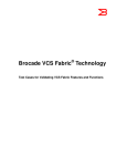
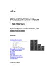
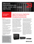
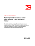
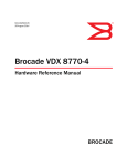
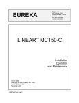
53-1002085-02
15 December, 2011
®
Brocade VDX 6720
QuickStart Guide
Supporting the VDX 6720-24 and VDX 6720-60
53-1002085-02
*53-1002085-02*
Copyright © 2010 Brocade Communications Systems, Inc. All Rights Reserved.
Brocade, the B-wing symbol, BigIron, DCFM, DCX, Fabric OS, FastIron, IronView, NetIron, SAN Health, ServerIron, TurboIron and Wingspan are
registered trademarks, and Brocade Assurance, Brocade NET Health, Brocade One, Extraordinary Networks, MyBrocade, and VCS are trademarks
of Brocade Communications Systems, Inc., in the United States and/or in other countries. All other brands, products, or service names are or may
be trademarks or service marks of, and are used to identify, products or services of their respective owners.
Notice: This document is for informational purposes only and does not set forth any warranty, expressed or implied, concerning any equipment,
equipment feature, or service offered or to be offered by Brocade. Brocade reserves the right to make changes to this document at any time,
without notice, and assumes no responsibility for its use. This informational document describes features that may not be currently available.
Contact a Brocade sales office for information on feature and product availability. Export of technical data contained in this document may
require an export license from the United States government.
Brocade Communications Systems, Incorporated
Corporate and Latin American Headquarters
Brocade Communications Systems, Inc.
130 Holger Way
San Jose, CA 95134
Tel: 1-408-333-8000
Fax: 1-408-333-8101
E-mail: [email protected]
Asia-Pacific Headquarters
Brocade Communications Systems China HK, Ltd.
No. 1 Guanghua Road
Chao Yang District
Units 2718 and 2818
Beijing 100020, China
Tel: +8610 6588 8888
Fax: +8610 6588 9999
E-mail: [email protected]
European Headquarters
Brocade Communications Switzerland Sàrl
Centre Swissair
Tour B - 4ème étage
29, Route de l'Aéroport
Case Postale 105
CH-1215 Genève 15
Switzerland
Tel: +41 22 799 5640
Fax: +41 22 799 5641
E-mail: [email protected]
Asia-Pacific Headquarters
Brocade Communications Systems Co., Ltd. (Shenzhen WFOE)
Citic Plaza
No. 233 Tian He Road North
Unit 1308 – 13th Floor
Guangzhou, China
Tel: +8620 3891 2000
Fax: +8620 3891 2111
E-mail: [email protected]
Document History
The following table lists all published versions of the Brocade VDX 6720 QuickStart Guide.
Title
Publication number
Summary of changes
Date
Brocade VDX 6720 QuickStart Guide
53-1002085-01
New document
December 2010
Brocade VDX 6720 QuickStart Guide
53-1002085-02
Removed reference to
Family Doc CD
December 2011
2 of 12
Brocade VDX 6720 QuickStart Guide
Publication Number: 53-1002085-02
Overview
This Quick Start guide is intended as an overview to help experienced installers unpack, install, and configure the
Brocade VDX 6720 quickly. For more detailed installation and configuration instructions, see the Brocade Network
OS Administrator’s Guide and the Brocade Network OS Command Reference Manual.
NOTE
Throughout this document, the Brocade VDX 6720 is referred to as the switch.
Items included with the Brocade VDX 6720
The following items are included with the standard shipment of a fully-configured Brocade VDX 6720. When you
open the Brocade VDX 6720 packaging, verify that these items are included in the package and that no damage has
occurred during shipping:
• The Brocade VDX 6720 switch, either the 24-port or 60-port version
• One accessory kit, containing the following items:
• Serial cable with an RJ45 connector
• 6 ft. power cords (2)
• Rubber feet, required for setting up the switch as a standalone unit
• Brocade Documentation Online document
• Brocade VDX 6720 QuickStart Guide (this publication)
Installation and safety considerations
You can install a Brocade VDX 6720 switch in the following ways:
• As a standalone unit on a flat surface.
• In an EIA cabinet using a fixed-rail rack mount kit. The optional fixed-rail rack mount kit can be ordered from
your switch retailer. Both the 24”-32” rack depth kit and the 28”-29” rack depth kit will work with the VDX
6720 switches.
• In an EIA cabinet using an optional flush-mount rack kit for switches. The optional flush-mount rack kit for
switches can be ordered from your switch retailer.
• Mounting a VDX6720 in the Idataplex IBM 17” depth rack requires an Idataplex rack mount kit, Brocade
part number 60-1001519-01.
Electrical considerations
To install and operate the switch successfully, ensure the following:
• The primary outlet is correctly wired, protected by a circuit breaker, and grounded in accordance with local
electrical codes.
• The supply circuit, line fusing, and wire size are adequate, as specified by the electrical rating on the switch
nameplate.
• The power supply standards provided in Table 1, “Power Supply Specifications” are met.
Brocade VDX 6720 QuickStart Guide
Publication Number: 53-1002085-02
3 of 12
TABLE 1
.
Power Supply Specifications
Specification
Value
Maximum output
250 watts, 4 amps, 12 VDC - VDX 6720-24
500 watts, 7 amps, 12 VDC - VDX 6720-60
Maximum AC power consumption
146.2 W - VDX 6720-24
360 W - VDX 6720-60
System DC power consumption (excluding power supply
and fan FRUs)
Idle: 182.4 W
Maximum: 306 W
Input system power (including power supply and fan
FRUs)
Idle: 206 W
Maximum: 306 W
Input voltage
85-264 VAC
Input line frequency
47-63 Hz
BTU rating
1044.11 BTU/hr
Inrush current
Maximum of 50A
Input line protection
AC lines are fused
Environmental considerations
For successful installation and operation of the switch, ensure that the following environmental requirements are
met:
• Because the Brocade VDX 6720 can be ordered with fans that either move air front to back or back to front,
be sure to orient your switch with the airflow pattern of any other devices in the rack.
• All equipment in the rack should force air in the same direction to avoid intake of exhaust air.
• A maximum of 102 cubic meters/hour (60 cubic feet/minute) and a minimum of 74.8 cubic meters/hour
(44 cubic feet/minute) of air flow is available to the air intake vents.
• The ambient air temperature does not exceed 40° C (104° F) while the switch is operating.
Cabinet considerations
For successful installation and operation of the switch in a cabinet, ensure the following cabinet requirements are
met:
• The cabinet must be a standard EIA cabinet.
• A cabinet space that is one rack unit (1U for VDX6720-24) or two rack units (2U for VDX6720-60) high
depending on the platform ordered; 4.45 cm (1.75 inches) or 8.90 cm (3.50 inches) high and 48.3 cm (19
inches) wide.
• The equipment in the cabinet is grounded through a reliable branch circuit connection and maintains
ground at all times. Do not rely on a secondary connection to a branch circuit, such as a power strip.
• Airflow and temperature requirements are met on an ongoing basis, particularly if the switch is installed in a
closed or multi-cabinet assembly.
• The additional weight of the switch does not exceed the cabinet’s weight limits or unbalance the cabinet in
any way.
• The cabinet is secured to ensure stability in case of unexpected movement, such as an earthquake.
4 of 12
Brocade VDX 6720 QuickStart Guide
Publication Number: 53-1002085-02
Recommendations for cable management
The minimum bend radius for a 50 micron cable is 2 inches under full tensile load and 1.2 inches with no tensile
load.
Cables can be organized and managed in a variety of ways, for example, using cable channels on the sides of the
cabinet or patch panels to minimize cable management. Following is a list of recommendations:
NOTE
You should not use tie wraps with optical cables because they are easily overtightened and can damage the optic
fibers. Velcro-like wraps are recommended.
• Plan for rack space required for cable management before installing the switch.
• Leave at least 1 m (3.28 ft) of slack for each port cable. This provides room to remove and replace the
switch, allows for inadvertent movement of the rack, and helps prevent the cables from being bent to less
than the minimum bend radius.
• For easier maintenance, label the cables and record the devices to which they are connected.
• Keep LEDs visible by routing port cables and other cables away from the LEDs.
Items required for installation
The following items are required for installing, configuring, and connecting the Brocade VDX 6720 for use in a
network and fabric:
•
•
•
•
•
Workstation with an installed terminal emulator, such as HyperTerminal
Unused IP address and corresponding subnet mask and gateway address
Serial cable (provided)
Ethernet cable
Brocade-branded SFP (1GbE) or SFP+s (10GbE) and compatible cables and/or direct-attach copper and
optical cables
• Access to an FTP server or Brocade-branded USB device for backing up the switch configuration (optional)
Standalone installation for a Brocade VDX 6720
Perform this task to install the Brocade VDX 6720 as a standalone unit.
1. Unpack the Brocade VDX 6720 and verify the items listed on “Items included with the Brocade VDX 6720.”
Verify the items are present and undamaged.
2. Apply the adhesive rubber feet. Applying the rubber feet onto the switch helps prevent the switch from sliding off
the supporting surface.
a.
Clean the indentations at each corner of the bottom of the switch to ensure that they are free of dust or
other debris that might lessen the adhesion of the feet.
b.
With the adhesive side against the chassis, place one rubber foot in each indentation and press into place.
3. Place the switch on a flat, sturdy surface.
4. Provide power to the switch as described in “Providing power to the switch.”
Brocade VDX 6720 QuickStart Guide
Publication Number: 53-1002085-02
5 of 12
ATTENTION
Do not connect the switch to the network until the IP address is correctly set. For instructions on how to set the IP
address, see “Setting the switch IP address.”
Rack installation for a Brocade VDX 6720
Follow the installation instructions shipped with the appropriate rack mount kit:
• To install the switch into a fixed-rail rack, refer to the Fixed Rack Mount Kit (24”-32”) Installation Procedure
or the Fixed Rack Mount Kit Installation Procedure.
• To install the switch into Telco 2-post rack, refer to the Flush Mount Rack Mount Kit Installation Procedure.
Providing power to the switch
Perform the following steps to provide power to the Brocade VDX 6720.
1. Connect the power cords to both power supplies, and then to power sources on separate circuits to protect
against AC failure. Ensure that the cords have a minimum service loop of 6 in. available and are routed to avoid
stress.
2. Power on the power supplies by flipping both AC switches to the “I” symbol (VDX 6720-24 only, power supplies
for VDX 6720-60 power up automatically when plugged in). The power supply LEDs display amber until POST is
complete, and then change to green. The switch usually requires several minutes to boot and complete POST.
ATTENTION
Power is supplied to the switch as soon as the first power supply is connected and turned on.
Verifying operation
After you have powered the system on and POST is complete, verify that the switch is working properly.
1. Verify that the power supply LEDs are solid green.
2. Verify that the system status LED is solid green.
3. The port LEDs should be lit during POST activities. When POST is complete, only the LEDs for ports connected to
other devices should be green.
Refer to the Brocade VDX 6720 Hardware Reference Manual for more details on the LED patterns.
Creating a serial connection
You perform all configuration tasks in this guide using a serial connection from a workstation or terminal to the
switch.
Complete the following steps to create a serial connection to the switch.
6 of 12
Brocade VDX 6720 QuickStart Guide
Publication Number: 53-1002085-02
1. Connect the serial cable to the serial port on the switch and to an RS-232 serial port on the workstation or
terminal device.
If the serial port on the workstation or terminal device is RJ45 instead of RS-232, remove the adapter on the
end of the serial cable and insert the exposed RJ45 connector into the RJ45 serial port on the workstation.
2. Open a terminal emulator application (such as HyperTerminal on a PC, or TERM, TIP, or Kermit in a UNIX
environment), and configure the application as follows:
• In a Windows environment, enter the following values: 9600 bits per second, 8 databits, no parity, 1 stop
bit, and no flow control.
• In a UNIX environment using TIP, enter the following string at the prompt:
tip /dev/ttyb -9600.
If ttyb is already in use, use ttya instead.
Assigning permanent passwords
When you log in for the first time, Brocade recommends that you change the passwords for the default accounts.
The factory-configured default accounts on the switch are admin, user, and root. Use the default administrative
account as shown in Table 2 to log in to the switch for the first time and to perform the basic configuration tasks.
The root account is reserved for development and manufacturing. The user account is read-only and used primarily
for system monitoring.
TABLE 2
Default administrative account names and passwords
Account type
Login name
Password
Administrative
admin
password
User account (read-only)
user
password
Changing the default account passwords
When you change the default account password after you log in for the first time, only the default password rule is in
effect. The rule specifies a minimum password length of eight characters. For advanced user and role management,
including setting password rules, refer to the Security chapter of the Brocade Network OS Administrator’s Guide.
1. Enter the configure terminal command to enter the global configuration mode.
2. Enter the username command followed by the account name and the password parameter.
3. When prompted, enter the new password. and press Enter.
Switch# configure terminal
Entering configuration mode terminal
switch(config)# username admin password
(<WORD>;;User password satisfying password-attributes):********
Brocade VDX 6720 QuickStart Guide
Publication Number: 53-1002085-02
7 of 12
Setting the switch IP address
You can configure the Brocade VDX 6720 with a static IP address, or you can use a DHCP (Dynamic Host
Configuration Protocol) server to set the IP address of the switch. DHCP is enabled by default. The Brocade VDX
6720 supports both IPv4 and IPv6 format addresses. For information about setting static IP addresses and
stateless IPv6 addresses, please see the Brocade Network OS Administrator’s Guide.
Using DHCP to set the IP address
When using DHCP, the Brocade VDX 6720 obtains its IP address, subnet mask, and default gateway address from
the DHCP server. The DHCP client can only connect to a DHCP server that is on the same subnet as the switch. If
your DHCP server is not on the same subnet as the Brocade VDX 6720, use a static IP address.
To set an IPv4 IP address using DHCP use the following commands:
1. Log into the switch using the admin account.
2. Use the ip address command:
switch(config)# interface Management 1/0
switch(config-Management-1/0)# ip address dhcp
To set an IPv4 IP address using DHCP use the following commands:
Enabling and disabling Brocade VCS mode
Enable or disable a single switch for VCS™ mode as soon as passwords have been assigned and an IP address has
been set. Enabling VCS mode is disruptive since a reboot is required once the mode has been enabled. Enabling or
disabling VCS mode also causes the default configuration file for that mode to be applied.
The basic configuration tasks include enabling or disabling VCS mode explicitly, setting VCS parameters, and
applying the default configuration. If you disable VCS mode, you do not have to set the other parameters. For more
details about enabling VCS mode and setting VCS parameters, please see the Brocade Network OS Administrator’s
Guide and the Brocade Network OS Command Reference Guide.
Enabling VCS mode
Perform the following steps to enable VCS mode.
1. Log in to the switch using an account that has the admin role.
2. Enter the vcs enable command, including the RBridge parameter, as in the example below.
vcs rbridgeid 1 enable
3. The switch reboots when you confirm that you want to enable VCS mode.
When the switch comes back up, if it is connected to other VCS-enabled switches the negotiation protocols
begin, determining which switch in the fabric is the principal switch and making sure that all domain IDs, and
therefore RBridge IDs, are unique. Should the insistent domain ID not be unique, you can change it. Once the
domain IDs are determined to be unique, they are equated to the RBridge IDs.
The switch with the lowest World Wide Name (WWN) becomes the principal switch, primarily for purposes of
determining the uniqueness of the ID of the other switches in the fabric. The WWN is a unique identifier burned
into the switch at the factory.
8 of 12
Brocade VDX 6720 QuickStart Guide
Publication Number: 53-1002085-02
Another parameters that can be changed if necessary is the VCS ID. This identifies the VCS fabric of which the
switch can be a part. By default, the VCS of every VDX 6720 is 1. Change the VCS ID if you need to create a new,
separate VCS fabric. If you need to change the VCS ID, use the vcs-id x parameter, where x is the new VCS ID
number.
vcs rbridgeid 1 vcsid 2 enable
4. Enter the copy running-config startup-config command to apply the currently running configuration, including
any changes made, to the startup configuration. You must type in the entire command, there is no autocomplete
for it. This is important to capture any changes that have been made to the running configuration so that they
will persist the next time the switch reboots in the same mode.
5. Reboot the switch.
When the switch comes back up it will be enabled in VCS mode.
Disabling VCS mode
Perform the following step to disable VCS mode.
1. Log in to the switch using an account that has the admin role.
2. Enter the no vcs enable command. The command removes the current running configuration and resets the
switch to the default standalone configuration when it reboots.
The switch reboots when you confirm that you want to disable VCS mode.
When the switch comes back up it will be enabled in standalone mode.
Configuring switch ports
By default, the interfaces are not configured as switch ports. In order to put an interface in Layer 2 mode, use the
following command in Interface Configuration mode.
switch(conf-if-te-1/0/3)#switchport
To remove an interface from Layer 2 mode, use the following command
switch(conf-if-te-1/0/3)#no switchport
Connecting network devices
Installing and connecting an SFP+ transceiver
The Brocade VDX 6720 supports only Brocade-branded SFP+ optical or copper transceivers. For its DCB
connections, the Brocade VDX 6720 uses SFP+ transceivers that support either optical or Brocade-branded direct
attached copper and optical (Laserwire) cables. The optical SFP+ transceivers support both SR (Short Reach) and
LR (Long Reach) modules. Direct attached copper cables support distances of 1 meter, 3 meters, and 5 meters.
Direct attached optical cables support distances of 10 meters and 20 meters.
To monitor the transceivers, the show media command output shows the transceiver information for all interfaces
on the switch. Any unqualified transceiver may be disabled and a log message is generated.
Complete the following steps to install an SFP+.
Brocade VDX 6720 QuickStart Guide
Publication Number: 53-1002085-02
9 of 12
1. Remove any protector plugs from the transceivers and the ports.
2. Making sure that the bail (wire handle) is in the unlocked position, place the transceiver in the correctly oriented
position on the port, as shown in Figure 1.
3. Slide the SFP+ into the port until you feel it click into place; then close the bail.
!
FIGURE 1
Installing an SFP+ in the upper row of port slots
4. If this is not a direct-connect unit, remove the protective caps from the cable end and position the cable so that
it is correctly oriented to the transceiver.
5. Insert the cable into the transceiver until it is firmly seated and the latching mechanism clicks.
10 of 12
Brocade VDX 6720 QuickStart Guide
Publication Number: 53-1002085-02
!
FIGURE 2
Inserting a cable into an SFP+
Connecting to Ethernet or fast Ethernet hubs
For copper connections to Ethernet hubs, a 10/100Base-TX or 1000Base-T switch, or another Brocade device, a
crossover cable is required. If the hub is equipped with an uplink port, it will require a straight-through cable instead
of a crossover cable.
NOTE
The 802.3ab standard (automatic MDI or MDIX detection) calls for automatic negotiation of the connection between
two 1000Base-T ports. Therefore, a crossover cable may not be required; a straight-through cable may work as well.
Connecting to workstations, servers, or routers
Straight-through UTP cabling is required for direct UTP attachment to workstations, servers, or routers using network
interface cards (NICs).
Fiber cabling is required for direct attachment to Gigabit NICs/CNAs or switches and routers through fiber ports.
Connecting a network device to a fiber port
For direct attachment from the Brocade device to a Gigabit NIC, switch, or router, fiber cabling with an LC connector
is required. Refer to “Installing and connecting an SFP+ transceiver” above for details about installing SFPs and
cables.
Brocade VDX 6720 QuickStart Guide
Publication Number: 53-1002085-02
11 of 12
12 of 12
Brocade VDX 6720 QuickStart Guide
Publication Number: 53-1002085-02