1
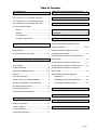
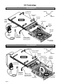
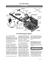
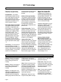
Braun UVL® Under Vehicle Wheelchair Lifts
L
V
U
Owner's Manual for:
UVL
®
Series
Under Vehicle Wheelchair Lifts
Including Models:
• UVL603A
• UVL603B
• UVL603E
• UVL604XA
• UVL604XB
• UVL604XC
• UVL604XD
• UVL855R
• UVL855RH
Note to Dealer:
Provide this manual
to the consumer.
See inside cover for
warranty/registration
information.
and Special Order
UVL® Series Lift Models
WARNING
Ow
ner
's
Ma
nu
al
®
"Providing Access to the World"
®
Braun UVL Series
International Corporate Hdqrs: P.O. Box 310 Winamac, IN 46996 USA
1-800-THE LIFT
(219) 946-6153
FAX: (219) 946-4670
Read manual
before operating
lift. Failure to do
so may result in
serious bodily
injury and/or
property damage.
Keep manual in
lift vehicle.
89001
September 1998
Patent #4,958,979
Congratulations
We at The Braun Corporation wish to express our fullest appreciation
on your new purchase. With you in mind, our skilled craftsmen have designed and
assembled the finest lift available.
This manual includes safety precautions, lift operating instructions, manual operating
instructions, and instructions for maintenance and lubrication procedures.
Your lift is built for dependability, and will bring you years of pleasure
and independence, as long as maintenance is performed regularly
and the lift is operated by an instructed person.
Sincerely,
THE BRAUN CORPORATION
Ralph W. Braun
Chief Executive Officer
Warranty/Registration Instructions
Immediately upon receiving:
Examine the unit for any damage. Notify the
carrier at once with any claims.
OWNER'S WARRANTY REGISTRATION
PURCHASED FROM
Two warranty/registration cards (shown right) are
protected in a clear envelope and attached to the
lift protective shipping wrap. The sales representative must process one of the cards. The consumer must fill out the other card and mail it to
The Braun Corporation. The warranty is provided
on the back cover of this manual.
OWNER
DATE INSTALLED
NAME
ADDRESS
CITY
TELEPHONE
STATE
ZIP
TO VALIDATE WARRANTY
REGISTRATION CARDS MUST BE RETURNED TO THE BRAUN CORPORATION.
Sample Warranty/Registration Card
The Braun Serial No./Series No. identification tag (shown below) is located on the left platform side
plate (outboard end). This I.D. tag contains the product identification information provided on the
Warranty/Registration card. Record the information in the space provided. This information must
be provided when filing a warranty claim or ordering parts.
Lift Model No.
Lift Serial No.
THE BRAUN CORPORATION
P.O. BOX 310 WINAMAC IN
219-946-6153
Series No.
MODEL
UVL603A
SERIAL NUMBER
DOM
OD . 2632 . .
0597
PATENT 4,958,979
Lift Series No.
Model No.
46996
Date of Manufacture
Serial No.
Date of Manufacture
Sample Serial No./Series No. Identification Tag
RETAIN THIS INFORMATION FOR FUTURE USE. YOU MUST HAVE THIS INFORMATION WHEN
FILING A WARRANTY CLAIM OR ORDERING PARTS!
Table of Contents
Lift Terminology
UVL® 600 Series Lift Terminology Illustration ............ 2
Manual Bridge Plate Operating Instructions ......12
Dual Stationary Handrail Instructions .................13
UVL® 600X Series Lift Terminology Illustration .......... 2
UVL® 850 Series Lift Terminology Illustration ............. 3
Dual Manual Fold “P” Handrail Instructions ......13
Lift Terminology Description
General ................................................................ 3
Dual Manual Fold “U” Handrail (with Shield)
Direction .............................................................. 3
Instructions ...........................................................14
Lift Components .................................................. 4
Lift Actions and Functions ................................... 4
Lift Operation Safety
Manual Operating Instructions
Cable-Activated Platform Manual Release
System Introduction ............................................ 15, 16
Safety Symbols .......................................................... 5
Platform Carriage Assembly Drive Chain
Lift Operation Safety Precautions ........................... 5-7
Re-engagement Procedure ...................................... 16
To Manually Move Platform Out (Extend) From
Pre-Lift Operation Notes
Stow Position ............................................................ 16
To Manually Raise Platform To Floor Level .............. 17
General Safety ........................................................... 7
To Manually Lower Platform To Ground Level ......... 18
Outboard Roll Stop ................................................ 7, 8
To Manually Move Platform In (Retract) To
Bridge Plate (Inboard Roll Stop) ............................ 8, 9
Stow Position ............................................................ 19
Handrails .................................................................... 9
Outboard Roll Stop Manual Operation
Passenger Orientation ............................................... 9
Introduction ........................................................ 19
Vehicle (Floor Level) Loading/Unloading ................... 9
To Manually Lower Outboard Roll Stop ............. 20
Wheelchair-equipped Occupant Seat Belts ............... 9
To Reengage Outboard Roll Stop ..................... 20
Operation Procedure Review ................................... 10
Preventive Maintenance ........................................... 10
Maintenance and Lubrication ............................. 21
Cold Climate Recommendations .............................. 10
Decals ................................................................... 22
Lift Operating Instructions
Warranty/Registration Policy ..............................23
Before Lift Operation ................................................. 10
Vehicle Lift Door(s) ................................................... 10
Return Authorization Procedure ........................ 23
Lift Control Switches ................................................. 11
Control Switch Functions .......................................... 11
Page 1
Lift Terminology
UVL®600 Series Lift Terminology Illustration
Inboard
Lift Mounting
Brackets (4)
Chain Drive
Motor
Hand
Pump
(inside
cover)
Right
Left
Outboard
Hydraulic
Cylinder
Lift Housing
Lifting Arms
Rolling
Horizontal
Arms
Roll Stop
Actuator
T
LIF
UP
T
N
LIF
DOW
W
STO
LIFT
R
DOOSE
CLO
81812
WA
RN
ING
Push
manu T-han
and ally dle
lock out movein fully
to
Failubefor
enga platfo and
resulre to e drivin
ge rm
deplot in lock gplatfo in
unint platfovehicrm
platfoymen
resul rm t. ende rm le.
may
and/ot in deploUnintd platfo
serio ymenende rm
r prope
us t d
rty bodilmay
dama y injury
Do
ge.
not
rem
ove
!
Pump
Module
81823
Platform
Hand-Held
Attendant's
Control Box
Platform Cableactivated Manual
Release System
Outboard
Roll Stop
UVL®600X Series Lift Terminology Illustration
Inboard
Lift Mounting
Brackets (4)
Chain Drive Motor
(inside cover)
Hydraulic
Cylinder
Lift Housing
Right
Left
Outboard
Bridge Plate
(Inboard Roll Stop)
Manual
Folding “P”
Handrails
Rolling
Horizontal
Arms
Hand Pump
(inside cover)
T
LIF
UP
T
N
LIF
DOW
W
STO
LIFT
Roll Stop
Actuator
R
DOOSE
CLO
81812
WA
RN
ING
Push
manu T-han
and ally dle
lock out movein fully
to
Failubefor
enga platfo and
resulre to e drivin
ge rm
deplot in lock gplatfo in
unint platfovehicrm
platfoymen
resul rm t. ende rm le.
may
and/ot in deploUnintd platfo
serio ymenende rm
r prope
us t d
rty bodilmay
dama y injury
Do
ge.
not
rem
ove!
Pump
Module
81823
Hand-Held
Attendant's
Control Box
Platform
Platform Cableactivated Manual
Release System
Lifting Arms
Page 2
Outboard
Roll Stop
Lift Terminology
UVL®850 Series Lift Terminology Illustration
Inboard
Lift Mounting
Brackets (4)
Chain Drive
Motor
Hydraulic
Cylinder
Lift Housing
Left
Right
Outboard
Inboard Roll Stop
(Bridge Plate)
Hand Pump
(inside cover)
Manual Fold
“U” Handrails
with Shields
T
LIF
UP
T
N
LIF
DOW
W
STO
LIFT
R
DOOSE
CLO
81812
Roll Stop
Actuator
WA
RNI
NG
Push
manu T-han
and ally dle
lock out movein fully
to
Failurbefor
engagplatfo and
resulte to e drivine rm
deplo in lock gplatfo in
unint platfovehicrm
platfoymen
resultrm t. ended rm le.
may
and/o in deploUnint platfo
seriouymenended rm
r prope
s t may
rty bodily
dama injury
Do
ge.
not
rem
ove!
Pump
Module
81823
Hand-Held
Attendant's
Control Box
Rolling
Horizontal
Arms
Platform
Platform Cable-activated
Manual Release System
Outboard
Roll Stop
Lifting Arms
Lift Terminology Description
The UVL Lift Series includes
three classifications of lifts
(UVL600 Series, UVL600X Series
and UVL850 Series). Refer to the
illustrations on pages 2 and 3 for
the visual differences in lift
configurations and identification
of lift components.
UVL600 Series lift models are
consumer oriented (intended for
operation by the wheelchair
passenger). UVL600X lift models
are commercial oriented and ADA
compliant (intended for operation
by an attendant). UVL600 Series
and UVL600X lift platforms raise
and lower with an “arcing” motion.
UVL600 Series lifts offer a variety
of options including bridge plates
(inboard roll stops) and handrails.
UVL850 Series lifts are commer-
cial oriented, ADA compliant and
designed for use in vehicles with
increased floor-to-ground requirements such as buses, trailers and
motor homes. UVL850 lift
platforms travel vertically straight
up and down (no “arcing” motion).
UVL lift models provide fully
automatic operation of all lift
functions as well as optional
automatic door operators (if so
equipped). Basic lift operation
procedures are identical for all
UVL Series lift models. The
operating instructions contained
in this manual address the lift
control switches and the corresponding lift functions. Separate
instructions are provided for
operation of manual bridge plates
(inboard roll stops) and handrails
(stationary and folding) that may
be present on your particular lift
model. Instructions are provided
for manual operation of the lift in
event of power or equipment
failure.
Terminology: Become familiar
with the terminology that will be
used throughout this manual.
Become familiar with the identification of lift components and their
functions.
Direction:
The terms "left," "right," "inboard,"
and "outboard" will be used
throughout this manual to indicate
direction (as viewed from outside
the vehicle looking directly at the
lift outboard roll stop). Refer to
the Lift Terminology Illustrations
for clarification of direction terms.
Page 3
Lift Terminology
Lift Components:
Refer to the Lift Terminology
Illustrations on pages 2 and 3.
Pump Module: The remote
mounted pump module consists
of the main hydraulic pump, the
manual hand pump, the logic
control board and other electrical
components that power the lift
electric/hydraulic systems.
Hand-held Switch Control Box:
The standard hand-held control
switchbox is connected to the
pump module. The control box is
equipped with four push-button
switches, (UP, DOWN, STOW,
and DOOR CLOSE). The
switches activate the fully automatic lift functions as well as
optional automatic door operators (if so equipped). Details
regarding the control switches
and their functions are provided in
the Lift Operation section (page
11).
Lift Housing: The lift housing is
the metal structure (casing)
mounted under the vehicle which
contains and protects the platform
carriage assembly. The housing
contains all lift components
except the power (pump) module
when the lift is in the stowed
position.
Platform Carriage Assembly:
The platform carriage assembly
includes the platform assembly,
the lifting arms, the rolling horizontal arms that carry the platform assembly in and out of the
housing and the electrical/
hydraulic drive components that
power the lift.
Platform Assembly: The lift
platform assembly consists of the
flat aluminum plate with raised
diamond embossing upon which
the wheelchair is positioned, the
outboard roll stop, the inboard roll
stop (if so equipped) and optional
handrails (if so equipped).
Outboard Roll Stop: The
outboard roll stop is the automatic
electric actuator-activated outer
barrier that provides a ramp for
wheelchair loading and unloading
at ground level. Photos and
further details regarding the
outboard roll stop operation are
provided in the Pre-Lift Operation
Notes section (pages 7 and 8).
Bridge Plate (Inboard Roll
Stop): UVL lift models are
equipped with an automatic or
manually operated bridge plate
(except model UVL603A). The
bridge plate bridges the gap
between the lift platform and the
vehicle floor. Bridge plates also
serve as inboard roll stops.
Automatic bridge plates are fullyautomatic in operation and are
activated by the lift control
switches (no attendant required).
Manual bridge plates must be
operated by an attendant. Further details and instructions for
operation of manual bridge plates
are provided on page 12 of this
manual.
Platform Cable-activated
Manual Release System: A
cable-activated manual release
system releases the platform
carriage assembly drive chain to
allow the platform carriage
assembly to be manually moved
out (extended) or moved in
(retracted), should it be necessary. Complete details and
operating procedures are provided on pages 15-19.
Lift Actions and Functions:
Extend: Extend is the action of
the platfom carriage assembly
moving (rolling) out of the lift
housing.
Retract: Retract is the action of
the platfom carriage assembly
moving (rolling) into the lift
housing.
Deploy: Lift deployment is the
action of the lift platform carriage
assembly extending (moving
outward) from the housing and
lowering to ground level when the
Page 4
DOWN switch is activated or
raising to floor level when the UP
switch is activated.
Stow: Stow is the action of the
lift platform carriage assembly
retracting (moving inward) into
the carriage assembly housing.
During the stow function, the
platform will automatically raise or
lower to stow level before retracting into the housing.
Stow Level: Stow level is the
height that the platfom carriage
assembly moves in and moves
out of the lift housing.
Floor Level: Floor level is the
height that the platfom carriage
assembly raises to in order for the
wheelchair passenger to enter
and exit the vehicle.
Note: Further details regarding
lift control switches and the
corresponding lift functions are
provided in the Lift Operating
Instructions on pages 10 and 11.
Lift Operation Safety
Safety Symbols
SAFETY FIRST! Know That....
All information contained
in this manual and
supplements (if included), is
provided for your safety. Familiarity with proper operation
instructions as well as proper
installation and maintenance
procedures are necessary to
ensure safe, troublefree operation. Safety precautions are
provided to identify potentially
hazardous situations and provide
instruction on how to avoid them.
A
D
B
WARNING
C
This symbol indicates
important safety
information regarding
a potentially hazardous situation that
could result in serious
bodily injury and/or
property damage.
CAUTION
This symbol indicates
important information
regarding how to
avoid a hazardous
situation that could
result in minor personal injury or property damage.
Note: Additional information provided to help clarify or detail a specific subject.
These symbols will appear throughout this manual as well as on the labels posted on your lift. Recognize
the seriousness of this information.
Lift Operation Safety Precautions
WARNING
If the lift operating
instructions, manual
operating instructions
and/or lift operation
safety precautions are
not fully understood,
contact The Braun
Corporation immediately. Failure to do so
may result in serious
bodily injury and/or
property damage.
WARNING
Read manual and supplement(s) before operating lift. Read
and become familiar with all safety precautions, pre-lift
operation notes, operating instructions and manual operating
instructions before operating the lift.
WARNING
Load and unload on level surface only.
WARNING
Engage vehicle parking brake before operating lift.
WARNING
Provide adequate clearance outside the vehicle to accommodate the lift before opening lift door(s) or operating lift.
WARNING
Inspect lift before operation. Do not operate lift if you suspect
lift damage, wear or any abnormal condition.
WARNING
Keep operator and bystanders clear of area in which the lift
operates.
WARNING
Stand clear of doors, stepwell and platform during lift operation.
WARNING
Do not jack the vehicle by the bumper or frame, this could cause damage to the drive shaft
and/or wheelchair lift.
WARNING
Whenever a wheelchair passenger (or standee) is on the platform, the:
• Passenger must be positioned in center of platform
• Wheelchair brakes must be locked
• Roll stop must be up (vertical)
• Passenger should grip both handrails if able (if so equipped).
Page 5
Lift Operation Safety
Lift Operation Safety Precautions (continued)
WARNING
Load and unload clear of vehicular traffic.
WARNING
Do not overload or abuse. The load rating applies to both the raising and lowering functions - continuous lifting capacity is 750 lbs.
WARNING Do not operate or board the lift if you or your lift operator are intoxicated.
WARNING Do not raise front wheelchair wheels (pull wheelie) when loading (boarding) the platform.
WARNING Open lift door(s) fully and secure before operating lift.
WARNING
Position and secure (buckle, engage, fasten, etc.) the wheelchair-equipped occupant seat
belt (torso restraint) before loading onto the wheelchair lift platform.
WARNING Fold manual-fold handrails down before stowing lift.
WARNING Lift occupant must keep hands, arms and all other body parts within the lift occupant area
and clear of moving parts.
WARNING
Platform must be positioned at floor level when loading or unloading in and out of vehicle.
WARNING
Do not use the outboard roll stop as a barrier (brake). Stop and brake wheelchair when
fully loaded on the platform (manually stop and brake manual wheelchairs — stop powered
wheelchairs with the wheelchair controls).
WARNING
Turn powered (electric) wheelchairs off when on lift platform.
WARNING
Press the DOWN switch until the entire platform rests on ground level (lowered fully) and
the outboard roll stop is fully unfolded (ramp position) before loading or unloading a passenger at ground level.
WARNING Outboard platform roll stop must be fully unfolded (ramp position) before front and rear
wheelchair wheels cross roll stop when loading or unloading at ground level.
WARNING Accidental activation of control switch(es) may cause unintended operation(s).
WARNING
After manually releasing platform, stow platform and push manual release T-handle in fully
and move platform in and out to engage platform lock before driving vehicle. Failure to lock
platform may result in unintended platform deployment.
WARNING Insert manual release T-handle fully before manually lowering or raising platform and
manually move platform in and out to engage platform lock.
WARNING Maintenance and lubrication procedures must be performed by authorized (certified)
service personnel.
WARNING Replace missing, worn or illegible decals.
WARNING Keep owner’s manual in lift vehicle at all times.
WARNING Never modify (alter) a Braun Corporation lift.
WARNING Do not use accessory devices not authorized by The Braun Corporation.
WARNING Do not remove any guards or covers.
Page 6
Lift Operation Safety
Lift Operation Safety Precautions (continued)
WARNING
Keep clear of any hydraulic leak.
WARNING
Failure to follow these safety precautions may result in serious bodily injury and/or property
damage.
Pre-Lift Operation Notes
WARNING
Read and become
familiar with all lift
operation safety
precautions, pre-lift
operation notes,
operating instructions
and manual operating
instructions prior to
operating the lift. If
this information is not
fully understood,
contact The Braun
Corporation immediately. Failure to do so
may result in serious
bodily injury and/or
property damage.
UVL® series lift models provide
fully automatic operation of all lift
functions as well as optional
automatic door operators (if so
equipped). It is the responsibility of the lift operator to properly activate all lift functions.
Read and become familiar with all
Lift Operation Safety Precautions,
Pre-Lift Operation Notes, Lift
Operating Instructions and
Manual Operating Instructions
before attempting lift operating
procedures. Contact The Braun
Corporation immediately if any of
this information is not understood.
Call 1-800-THE LIFT. The lift
owner's manual must be stored
in the lift vehicle at all times.
General Safety: The lift operator
(attendant) and bystanders must
keep clear of the area in which
the lift operates and clear of all
moving parts. Stand clear of
doors, stepwell and platform
during lift operation. The lift
occupant must keep hands, arms
and all other body parts within the
lift occupant area and clear of
moving parts.
DANGER
KEEP CLEAR OF MOVING PARTS
WARNING
Discontinue lift use
immediately if any lift
component does not
operate properly.
Failure to do so may
result in serious
bodily injury and/or
property damage.
Become familiar with all platform
features and the proper operation
of the platform components
before attempting lift operation.
Refer to Lift Terminology on
pages 2-4 for identification of and
description of specific lift components if not clearly depicted in this
section. Contact The Braun
Corporation at 1-800-THE LIFT
immediately if any of this information is not understood.
81819
Outboard Roll Stop: The
outboard roll stop is the automatic
electric actuator-activated outer
barrier that provides a ramp for
wheelchair loading and unloading
at ground level.
From ground level, the LIFT UP
function switch automatically
raises (rotates) the actuatoractivated roll stop to the upright
(vertical) position before the
Page 7
Pre-Lift Operation Notes
platform raises. Note: The lift
platform will not raise if the roll
stop is not in the UP position.
This is a built-in safety feature.
fully unfolded before the front
and rear wheelchair wheels (or
standee) have crossed the roll
stop.
The LIFT DOWN function lowers
the platform to ground level. The
outboard roll stop automatically
unfolds to ramp (horizontal)
position when the platform
contacts the ground to allow the
wheelchair passenger on or off of
the lift. The roll stop must be
Although the outboard roll stop is
lift-powered and fully-automatic in
operation, mechanical failures are
possible. Discontinue lift
operation immediately if the
roll stop does not operate
properly.
WARNING
Discontinue lift use
immediately if any lift
component does not
operate properly.
Failure to do so may
result in serious
bodily injury and/or
property damage.
Fully-Folded (Up-vertical)
Outboard Roll Stop
Fully-Unfolded
(Ramp position)
Outboard
Roll Stop
Outboard
Roll Stop
Electric
Actuator
Bridge Plate (Inboard Roll
Stop): UVL lift models may be
equipped with an automatic or
manually operated bridge plate
(except model UVL603A). The
bridge plate bridges the gap
between the lift platform and the
vehicle floor as well as serving as
an inboard roll stop.
Automatic Bridge Plate: Automatic bridge plates are spring-
Vehicle Floor
loaded to raise to vertical position
when the platform extends from
the stow position. The automatic
bridge plate folds down onto the
vehicle floor as the platform
raises to floor level. The bridge
plate automatically folds down to
the platform surface during the lift
stow function. Discontinue lift
operation immediately if the
automatic bridge plate does
not operate properly.
Automatic
Bridge Plate
(Inboard Roll Stop)
Manual Bridge Plates: Manual
bridge plates are attendant
operated. The bridge plate rests
on the platform surface when the
lift is in the stowed position.
When the platform is fullyextended, the bridge plate is
manually raised to the vertical
position. When the platform is
raised to floor level, the bridge
plate is manually lowered to the
vehicle floor (bridging position).
Vehicle Floor
Floor Level
(Bridging Position)
Platform Below
Floor Level
Page 8
Platform at
Floor Level
Vertical Position
Pre-Lift Operation Notes
Further details and instructions
for operation of manual bridge
plates are provided in the Manual
Bridge Plate Operating Instructions (see page 12).
Handrails: UVL lift models may
be equipped with one of three
types of handrails - Stationary
Handrails, Manual Fold “P”
Handrails or Manual Fold “U”
Handrails with Safety Side
Shields. Handrails are standard
equipment on most lift models
and optional equipment on
others. Passengers should grip
both handrails when on the lift
platform if possible.
Become familiar with the proper
operation of the style of handrail
your lift is equipped with (if so
WARNING
WARNING
Face outward and lock wheelchair
brakes before operating lift.
81814
Lift Passengers: Do not attempt
to load or unload a passenger in
a wheelchair or other apparatus
that does not fit on the platform
area. Do not exceed the 750
pound rated load capacity of the
lift.
Passenger Orientation (Boarding Direction): Inboard facing of
wheelchair passengers is not
prohibited, but outboard facing
of passengers is recommended
by The Braun Corporation.
Passengers loading from ground
level should back onto the
platform. Passengers loading
from floor level should proceed
onto the platform facing outward
(outward from the vehicle).
The passenger must be positioned in the center of the
platform to prevent side-to-side
load off-balance. The lift attendant (operator) should not ride on
the platform with the passenger.
Wheelchair brakes must be
locked whenever the passenger
is on the platform. Turn powered
(electric) wheelchairs off when on
platform.
If you are an attendant operating
equipped). Stationary handrails
remain in the upright (vertical
position) at all times and require
no operation procedures (see
page 13 for details). Refer to the
applicable handrail instructions
for details and operation procedures for folding handrails on
pages 13 and 14. Discontinue
lift operation if the handrails do
not operate properly.
the lift, it is your responsibility to
practice safe loading and unloading procedures. Observe your
passenger at all times during lift
operation.
Vehicle (Floor Level) Loading/
Unloading: The platform must
be fully raised (at floor level) and
the bridge plate must be properly
positioned (if equipped) when
loading or unloading passengers
in or out of the vehicle. Floor
level positioning of the UVL
platform is a fully automatic
function, but it is the responsibility of the lift operator to
ensure the platform and the
bridge plate (if equipped) are
properly positioned.
If the lift does not position the
platform properly, discontinue
lift use immediately and contact
an authorized Braun Corporation
dealer in your area or call The
Braun Corporation at 1-800-THE
LIFT. One of our national service
representatives will direct you to
an authorized service repairman
who will inspect your lift.
Wheelchair-equipped Occupant
Seat Belts: The Braun Corpora-
Position and secure
(buckle, engage,
fasten, etc.) the
wheelchair-equipped
occupant seat belt
before loading onto
the wheelchair lift
platform. Failure to
do so may result in
serious bodily injury
and/or property
damage.
tion recommends wheelchair
passengers position and buckle
their wheelchair-equipped seat
belt (torso restraint) as specified
by the manufacturer, before
loading onto a wheelchair lift.
Different types of disabilities
require different types of wheelchairs and different types of
wheelchair-equipped occupant
restraint belt systems (torso
restraints). It is the responsibility
of the wheelchair passenger to
have his or her wheelchair
equipped with an occupant
restraint (seat belt) under the
direction of their health care
professional. Wheelchair lift
attendants should be instructed on
any special needs and/or procedures required for safe transport of
wheelchair passengers.
Page 9
Pre-Lift Operation Notes
Operation Procedure Review:
The wheelchair lift user and/or
attendant should review the
safety precautions and operation
procedures appearing in this
manual with your wheelchair lift
sales representative (dealer),
before attempting lift operation.
Become familiar with the proper
operation of your lift before
operating the lift by yourself.
sales representative should also
instruct and demonstrate manual
operation procedures. Be
certain your sales representative
instructs and demonstrates the
proper reengagement procedure
of the manual cable release
system (see pages 15-19). Any
questions or concerns can be
answered by the sales representative at that time.
Operate the lift through all
functions with your sales representative on hand to ensure the
proper use and operation of the
wheelchair lift is understood. The
Do not operate your lift if you
suspect lift damage, wear or any
abnormal condition. Discontinue
lift use immediately and contact
an authorized Braun Corporation
dealer in your area or call The
Braun Corporation at 1-800-THE
LIFT. One of our national service
representatives will direct you to
an authorized service repairman
who will inspect your lift.
WARNING
Discontinue lift use
immediately if any lift
component does not
operate properly.
Failure to do so may
result in serious
bodily injury and/or
property damage.
WARNING
Read and become
familiar with all lift
operation safety
precautions, pre-lift
operation notes,
operating instructions
and manual operating
instructions prior to
operating the lift. If
this information is not
fully understood,
contact The Braun
Corporation immediately. Failure to do so
may result in serious
bodily injury and/or
property damage.
Page 10
Preventive Maintenance:
Maintenance is necessary to
ensure safe and trouble-free lift
operation. General preventive
maintenance consisting of
careful inspections of your lift
system and cleaning the lift
should be a part of your routine.
Simple inspections can detect
potential lift operational problems.
Regular preventive maintenance
will reduce potential lift operation
downtime and increase the
service life of the lift, as well as
possibly detecting potential
hazards. Exposure to harsh
weather elements or environmental conditions may require more
frequent maintenance and
lubrication procedures. See the
Maintenance and Lubrication
section for further details.
Cold Climate Recommendations: The vehicle in which the
lift is installed should be stored in
a garage or other sheltered place
if possible, especially during
inclement weather conditions.
When the lift is not in use, the lift
should be in the stowed position
to keep foreign objects, rain, ice,
snow, etc., from entering through
the lift opening or building up on
the platform surface.
Lift Operating Instructions
Lift Operating Instructions address the lift control switches and
the corresponding lift functions.
Separate instructions are provided for operation of manual
bridge plates (inboard roll stops)
and handrails that may be
present on your particular lift
model. Fold handrails down
before stowing lift.
In event of power or equipment
failure, refer to the Manual
Operating Instructions section.
Before lift operation, park the
vehicle on a level area, away
from vehicle traffic. Place the
vehicle transmission in “Park” and
engage the parking brake.
Vehicle Lift Door(s): Open
manual doors fully, being certain
the doors are secured in the fully
open position before operating
the lift. If your vehicle is equipped
with optional automatic door
operators, the doors will open
when the UP or DOWN switch is
pressed. The automatic door
operators will close when DOOR
CLOSE switch is pressed (only if
the lift platform is in the fully
stowed position).
Lift Operating Instructions
Lift Control Switches:
The UVL® logic control system provides fully automatic operation of all lift functions as well as optional automatic door operators (if so equipped).
Lift functions can be performed from any position
the platform happens to be in at the time the switch
button is pushed.
There are two types of hand controls available for
the UVL - the standard hand-held control switchbox,
or the optional remote control. Both types of
controls are equipped with four push-button
switches. The functions activated by both types of
controls are the same. The switch functions are
labeled. The function of each switch is described
below.
LIFT
UP
UP
DOWN
STOW
DOOR
CLOSE
LIFT
DOWN
STOW
LIFT
DOOR
CLOSE
THE BRAUN
CORPORATION
81812
86478
Hand-held Switchbox
(Standard Equipment)
Optional Remote
Control Transmitter
Remote Control Note: The effective range of the
remote control is 20 feet. A range further than 20
feet does not allow an attendant to observe and
assist the lift passenger.
Control Switch Functions:
UP: From the stowed position, the LIFT UP function
deploys (extends) the platform fully. The platform
then raises to floor level height and moves inward to
the vehicle floor level position (if applicable). Note:
When the lift is in the stowed position, power doors
automatically open when the UP switch is pressed
(if so equipped).
From ground level, the LIFT UP function will first
automatically raise (rotate) the outboard roll stop to
the upright (vertical) position. Note: The lift will not
raise if the roll stop is not in the UP position (built-in
safety feature). The platform then raises to floor
level height and moves inward to the vehicle floor
level position. Note: UVL600 and UVL600X lift
models move inward to floor level position with an
“arcing” motion. UVL850 Series lift models do not.
DOWN: The LIFT DOWN function lowers the
platform to ground level (regardless of the position
of the platform) and then unfolds the outboard roll
stop to the ramp (horizontal) position. From the
stowed position, the lift will extend and then lower.
Note: When the lift is in the stowed position, power
doors automatically open when the DOWN switch is
pressed (if so equipped).
STOW: The STOW LIFT function raises or lowers
the platform to stow level and then moves the
platform inward (retracts) to the stow position.
Note: The lift will not
stow with weight on the
platform (built-in safety
feature).
Fold handrails down
before stowing lift.
Failure to do so may
result in serious
bodily injury and/or
property damage.
WARNING
Fold handrails down
before stowing lift.
Failure to do so may
result in serious
bodily injury and/or
property damage.
DOOR CLOSE: When the vehicle is equipped with
automatic door openers (optional), the DOOR
CLOSE switch closes the doors. This function
operates only when the platform is stowed or fully
extended and below stow level.
Note: If any of these functions do not occur as
described, discontinue lift use immediately and
contact your sales representative or call The Braun
Corporation at 1-800-THE LIFT. One of our national
service representatives will direct you to an authorized service repairman who will inspect your lift.
In event of power or equipment failure, refer to
Manual Operating Instructions to manually operate
(stow) the lift, then contact your sales representative
for further instructions.
Page 11
Manual Bridge Plate Operating Instructions
A
Vertical Bridge Plate Engagement
Engagement
Notch
B
Floor Level
Bridge Plate
Manual Bridge Plate
Platform at Stow Level
The bridge plate bridges the gap between the lift platform
and the vehicle floor when the lift platform is raised fully
(positioned at floor level), as well as serving as an inboard
roll stop.
Manual bridge plates are attendant operated. The bridge
plate rests on the platform surface when the lift is in the
stowed position (see Photo A). When the platform is fully
extended and raised or lowered to the desired height, the
bridge plate is manually positioned as needed.
Bridge Plate
Engagement Bracket
C
Engaged
Vertical
Bridge Plate
When raised to the vertical position, the rear (left) end of
the plate engages a notch in the angled engagement
bracket located at the inboard end of the platform side
plate. See Photos B and C. The spring located on the
opposite end of the bridge plate hinge places rearward
pressure on the bridge plate to retain the plate in the
vertical position (engaged in bracket notch).
D
Vehicle Floor
t and Floor
Gap between Lif
Manual Bridge
Move vertical
bridge plate
to right to
disengage it,
and then
lower it to the
floor.
Vehicle Floor
Engaged - Vertical
Bridge Plate
Plate
Platform at Floor Level
When the platform is raised to floor level, the bridge plate
is manually lowered to the vehicle floor (bridging position)
by moving the bridge plate to the right to disengage it, and
then lowering it to the floor. From the floor level bridging
position, the bridge plate is manually raised to the vertical
position (see Photos D, E and F).
The bridge plate can be folded down to the platform
surface by the attendant before stowing the lift platform, or
the stowing (retracting) movement of the platform will push
the bridge plate down as it contacts the lift carriage.
Page 12
E
Platform at Floor Level
F
Vehicle Floor
Floor Level Bridge Plate
(Bridging Position)
Platform at Floor Level
Dual Stationary Handrail Instructions
Stationary handrails remain in the
upright (vertical position) at all
times. Handrail access slots are
provided in the lift housing cover.
Access slots are incorporated in
the vehicle floor or stairwell
during lift installation procedures.
The handrails travel in and out of
the access slots as the platform
carriage assembly retracts and
extends. Keep clear of the
handrail access slots during lift
operation.
WARNING
Stay clear of handrail
access slots during
lift operation. Failure
to do so may result in
serious bodily injury.
Stationary
Handrails
Keep clear of handrail access
slots during lift operation.
Lift Housing
Access
Slot
Cover with
Access Slots
Access Slot
Dual Manual Fold “P” Handrail Instructions
Folding “P” handrails are manually operated. The handrails rest
on the platform when the lift is not
in use. The handrails must be
folded down to the platform
(horizontal position) before
stowing the lift. The handrails are
lifted to the vertical position and
locked in position with a latch that
automatically engages the
platform bracket when fully
raised. Lifting the round knob
located on the vertical handrail
tube disengages the latch.
Deployed
“P” Handrails
W
STO
Y
LO
STOW
DE
P
Fold handrails down
before stowing lift.
Failure to do so may
result in serious
bodily injury and/or
property damage.
Stowed
“P” Handrails
Latch
Knob
PLOY
DE
WARNING
Latch Knob
Page 13
Dual Manual Fold “U” Handrail (with Shield) Instructions
Folding “U” handrails (with safety
shield) are manually operated.
The handrails rest on the platform
when the lift is not in use. The
handrails must be folded down to
the platform (horizontal position)
before stowing the lift.
Note: The bridge plate (inboard
roll stop) must be folded down
to the platform (horizontal position) before the handrails are
folded down.
The handrails are lifted to the
vertical position and locked in
position with a latch that automatically engages the platform
bracket when fully raised. Lifting
the round knob located on the
vertical handrail tube disengages
the latch.
To Deploy Handrails:
1. Lift front
(right)
handrail to
vertical
latched
position. Be
certain latch
is engaged.
UV
L
2. Lift rear (left)
handrail to
vertical
latched
position. Be
certain latch
is engaged.
UV
L
To Stow Handrails:
Before stowing lift:
1. Fold down
inboard roll
stop (bridge
plate).
Inboard
Roll Stop
WARNING
UV
L
Latch
Knob
Fold handrails down
before stowing lift.
Failure to do so may
result in serious
bodily injury and/or
property damage.
Latch
Knob
2. Lift round
latching knob to
disengage latch
and fold rear
(left) handrail
down to platform (horizontal
position).
Page 14
UV
L
3. Lift round
latching knob to
disengage latch
and fold front
(right) handrail
down to platform (horizontal
position).
UV
L
Manual Operating Instructions
The UVL has the capability of
being manually operated. If you
experience power or equipment
failure, refer to the Manual
Operating Instructions to manually operate the lift. Refer to the
Lift Operating Instructions for all
normal lift operation procedures
(such as loading and unloading
passengers). Follow all Lift
Operation Safety Precautions
at all times!
Familiarize yourself with the
components necessary to operate
the Manual Back-Up System (see
illustration at right and photos on
pages 17 and 18). The location
of the power pack and release
cable varies from vehicle to
vehicle (depending on your
particular installation).
The T-handle release cable
releases and engages the lift
platform to allow the platform to
be manually extended and
retracted. The manual back-up
pump (hand pump) is used to
manually lower and raise the
extended platform.
HAND
PUMP
Step-by-step instructions for
manually moving the platform
in and out, manually raising "T" HANDLE
RELEASE
and lowering the platform
CABLE
and manually lowering
(unfolding) the outboard roll
stop are provided on the following
pages. Refer to the applicable
Manual Operation instructions for
detailed procedures.
Always exercise extreme caution
when operating the lift manually.
Read the warning and the
safety information below and
on the following page! Read all
Manual Operating Instructions
before attempting to perform
manual operation procedures.
PUMP
HANDLE
POWER
PACK
MANUAL
DOWN
VALVE
Note: Location of power
pack and T-handle varies.
Note: Photos of the power
pack and T-handle appear
on pages 17 and 18.
Cable-Activated Platform Manual Release System
WARNING
Push T-handle in fully and
manually move platform in
and out to engage platform
lock before driving vehicle.
Failure to lock platform may
result in unintended platform
deployment. Unintended
platform deployment may
result in serious bodily injury
and/or property damage.
Platform Manual Release
System: A cable-activated
manual release system releases
and engages the platform carriage assembly drive chain to
allow the platform carriage
assembly to be manually moved
out (extended) or moved in
(retracted) as needed. A Thandle is provided on the release
cable for activation of the manual
release system (details follow).
Failure to manually lock the
platform carriage assembly (reengage the carriage assembly
drive chain) after manual deployment, will allow the platform to roll
in or out of housing unhindered
during vehicle movement. Failure
to lock the platform will also allow
the platform to roll in or out of
housing unhindered during hand
pump raising and lowering
procedures.
After manually moving the
platform in or out, it is extremely
important that the cable-activated
manual release is positively reengaged to secure (lock) the
platform carriage assembly before
loading a passenger on the
platform or before driving the
vehicle (reengagement procedure
outlined on following page).
After manually releasing
platform, push manual release
T-handle in fully and ensure
platform is locked before
driving lift vehicle. Uncontrolled and unintentional
platform deployment (inadvertent platform ejection) may
result in serious bodily injury
and/or property damage.
Page 15
Manual Operating Instructions
WARNING
Push T-handle in fully and
manually move platform in
and out to engage platform
lock before driving vehicle.
Failure to lock platform may
result in unintended platform
deployment. Unintended
platform deployment may
result in serious bodily injury
and/or property damage.
Note: The lift platform must be
pushed back into its carriage
compartment at least half-way
before reverting back to normal
(powered) operation. When the
lift is fully extended manually, it
does not activate the proper
switches for normal operation.
Returning (moving) the lift at least
half-way in allows for proper
switch activation.
Note: Before manually raising or
lowering platform, be sure to
reengage the release cable
mechanism by loosening (turning)
the “T” handle and pushing
inward. Failure to place “T”
handle in the original IN position
will allow the platform to move in
and out when trying to raise or
lower the platform with the hand
pump.
Sales Representative: Instruct
and demonstrate the proper reengagement procedure of the
manual release for all new UVL
owners at the point of sale or
delivery. Remind the consumer of
proper engagement procedures
when giving telephone instructions.
Step-by-step instructions for
manually moving the platform in
and out, manually raising and
lowering the platform and manually
lowering (unfolding) the outboard
roll stop are provided on the
following pages.
Platform Carriage Assembly Drive Chain Reengagement Procedure:
1
After manually moving the
platform in or out:
Read warning posted above!
1. Turn (loosen) the manual
release “T” handle.
3. Grasp the outer roll stop and
move the platform in and out
until the platform locks (chain
release assembly engages),
securing the platform carriage
assembly within the housing.
You will feel the release
mechanism engage.
2. Push the “T” handle in fully
(until handle bottoms out
against its mounting bracket).
2
TU
RN
TO
LO
CK
WA
RN
ING
Pu
s
ma h T-h
an nuall and
d
y le
loc out mo in fu
v
Fa k befoto en e pla lly a
il
g
n
res ure tore d age tform d
ri
de ult in loc vingplatf in
o
p
k
pla loym unin platf vehicrm
te
tf
o
res rm ent. nde orm le.
an ult in dep Unin d pla may
d/o se loy ten tfo
r p rio me de rm
rop us nt d
ert bo ma
y d dily y
am in
Do
ag jury
not
e.
rem
ove
!
81
82
3
To Manually Move Platform Out (Extend) From Stow Position:
2
1. Pull the “T” handle release
cable outward.
2. Turn the “T” handle to lock
platform into the released
position.
3. Carefully pull the platform out
to desired position.
Page 16
Read warning posted above!
Before raising or lowering the
platform, be sure to lock the
platform. Reengage the release
cable mechanism by loosening
(turning) the “T” handle and
pushing inward. Failure to place
“T” handle in the original IN
position (lock platform) will cause
the platform to move in and out
when trying to raise or lower the
platform with the hand pump.
1
TU
RN
TO
LO
CK
WA
RN
ING
Pu
s
ma h T-h
an nuall and
d
y le
loc out mo in fu
v
Fa k befoto en e pla lly a
il
g
n
res ure tore d age tform d
ri
de ult in loc vingplatf in
o
p
k
pla loym unin platf vehicrm
te
tf
res orm ent. nde orm le.
an ult in dep Unin d pla may
d/o se loy ten tfo
r p rio me de rm
rop us nt d
ert bo ma
y d dily y
am in
Do
ag jury
not
e.
rem
ove
!
81
82
3
Manual Operating Instructions
Hand Pump Handle
To Manually Raise Platform
To Floor Level:
A
B
Note: Disregard procedures for
manually moving the platform in or
out if not applicable.
Hand
Pump
1. Remove pump handle from
clips on side of power pack (or
other storage location).
Open
Close
(Down)
(Up/Stop)
2. Place handle through pump
cover access slot and into hand
pump. Stroke hand pump until
platform reaches floor height
(see Photo C).
Hand Pump Handle
Release
Valve
approximate 1/16" intervals
3. a. Pull “T” handle release cable
outward and b. turn “T” handle
to lock platform into the released position (see Figure 1).
maximum
30 inch lbs
4. Push platform in until it meets
floor of vehicle (if applicable).
minimum
15 inch lbs
OSE
CL
OPEN
seats
(stops)
Release Valve
Valve Tightening Specification:
Once valve seats (stops), tighten
15 to 30 inch pounds as shown.
b
a
C
a
TU
RN
TO
LO
CK
WA
RN
ING
WA
RN
ING
Pu
s
ma h T-h
an nuall and
d
y le
loc out mo in fu
v
Fa k befoto en e pla lly a
il
g
n
res ure tore d age tform d
ri
de ult in loc vingplatf in
plo u k p v orm
pla ym nin latf ehic
te
restform ent. nde orm le.
an ult in dep Unin d pla may
d/o se loy ten tfo
r p rio me de rm
rop us nt d
ert bo ma
y d dily y
am in
Do
ag jury
no
e.
t re
mo
ve!
Note: Grasp the outer roll stop
and move the platform in and
out until the platform locks.
You will feel the release mechanism engage. Read Platform
Carriage Assembly Drive
Chain Reengagement Procedure section on opposite page!
b
TU
RN
TO
LO
CK
Figure 1
5. Reengage the release cable
mechanism by a. turning the “T”
handle and b. pushing the “T”
handle in fully (see Figure 2).
81
82
3
Pu
s
ma h T-h
an nuall and
d
y le
loc out mo in fu
v
Fa k befoto en e pla lly a
il
g
n
res ure tore d age tform d
ri
de ult in loc vingplatf in
plo u k p v orm
pla ym nin latf ehic
te
restform ent. nde orm le.
an ult in dep Unin d pla may
d/o se loy ten tfo
r p rio me de rm
rop us nt d
ert bo ma
y d dily y
am in
Do
ag jury
not
e.
rem
ove
!
81
82
3
Figure 2
Page 17
Manual Operating Instructions
Hand Pump Handle
To Manually Lower Platform
To Ground Level:
A
B
Note: Disregard procedures for
manually moving the platform in or
out if not applicable.
Hand
Pump
When lowering platform from
floor level:
Open
Close
(Down)
(Up/Stop)
1. a. Pull “T” handle release cable
outward and b. turn “T” handle
to lock platform into the released position (see Figure 1).
2. Pull platform out fully (until it
stops), if applicable.
Release
Valve
approximate 1/16" intervals
maximum
30 inch lbs
minimum
15 inch lbs
OSE
CL
OPEN
seats
(stops)
Release Valve
Valve Tightening Specification:
Once valve seats (stops), tighten
15 to 30 inch pounds as shown.
b
a
TO
LO
CK
WA
RN
ING
Figure 1
Page 18
Pu
s
ma h T-h
an nuall and
d
y le
loc out mo in fu
v
Fa k befoto en e pla lly a
il
g
n
res ure tore d age tform d
ri
de ult in loc vingplatf in
plo u k p v orm
pla ym nin latf ehic
te
restform ent. nde orm le.
an ult in dep Unin d pla may
d/o se loy ten tfo
r p rio me de rm
rop us nt d
ert bo ma
y d dily y
am in
Do
ag jury
no
e.
t re
mo
ve!
3. Reengage the release cable
mechanism by a. turning the “T”
handle and b. pushing the “T”
handle in fully (see Figure 2).
Note: Grasp the outer roll stop
and move the platform in and
out until the platform locks.
You will feel the release mechanism engage. Read Platform
Carriage Assembly Drive
Chain Reengagement Procedure section on page 16!
81
82
3
C
4. Place slotted end of pump
handle onto hand pump down
(release) valve and turn counterclockwise (open 1/2 turn
only) to lower platform. See
Photo B.
5. Turn hand pump down (release)
valve clockwise (close) before
performing any other lift functions. See Photo B.
TU
RN
Hand Pump Handle
Note: Close hand pump
release valve securely before
operating lift. The lift will not
operate properly if the valve is
not in its fully clockwise position.
a
b
TU
RN
TO
LO
CK
WA
RN
ING
Pu
s
ma h T-h
an nuall and
d
y le
loc out mo in fu
v
Fa k befoto en e pla lly a
il
g
n
res ure tore d age tform d
ri
de ult in loc vingplatf in
plo u k p v orm
pla ym nin latf ehic
te
restform ent. nde orm le.
an ult in dep Unin d pla may
d/o se loy ten tfo
r p rio me de rm
rop us nt d
ert bo ma
y d dily y
am in
Do
ag jury
not
e.
rem
ove
!
81
82
3
Figure 2
Manual Operating Instructions
To Manually Move Platform Inward (Retract) To Stow Position:
3
Read Platform Carriage Assembly Drive Chain Reengagement
Procedure section on page 16!
WARNING
2
1. Position (raise or lower)
platform to stow level (height)
using procedures outlined on
pages 17 and 18.
TO
LO
CK
WA
RN
ING
2. Pull “T” handle release cable.
See Figure 1.
3. Turn “T” handle to lock platform in the released position.
See Figure 1.
TU
RN
Figure 1
Pu
s
ma h T-h
an nuall and
d
y le
loc out mo in fu
v
Fa k befoto en e pla lly a
il
g
n
res ure tore d age tform d
ri
de ult in loc vingplatf in
o
p
k
pla loym unin platf vehicrm
te
tf
res orm ent. nde orm le.
an ult in dep Unin d pla may
d/o se loy ten tfo
r p rio me de rm
rop us nt d
m
ert bo a
y d dily y
am in
Do
ag jury
not
e.
rem
ove
!
Push T-handle in fully and
manually move platform in
and out to engage platform
lock before driving vehicle.
Failure to lock platform may
result in unintended platform
deployment. Unintended
platform deployment may
result in serious bodily injury
and/or property damage.
81
82
3
a
4. Carefully push platform
inward to stow position.
5. Reengage the release cable
mechanism by a. turning the
“T” handle and b. pushing the
the “T” handle in fully (see
Figure 2). Grasp the outer roll
stop and move the platform in
and out until the platform
locks. You will feel the
release mechanism engage.
b
TU
RN
TO
LO
CK
WA
RN
ING
Figure 2
Pu
s
ma h T-h
an nuall and
d
y le
loc out mo in fu
v
Fa k befoto en e pla lly a
il
g
n
res ure tore d age tform d
ri
de ult in loc vingplatf in
plo u k p v orm
pla ym nin latf ehic
te
restform ent. nde orm le.
an ult in dep Unin d pla may
d/o se loy ten tfo
r p rio me de rm
rop us nt d
ert bo ma
y d dily y
am in
Do
ag jury
not
e.
rem
ove
!
81
82
3
Outboard Roll Stop Manual Operation
The automatic outboard roll stop is powered by an
electric actuator. In the event of power or equipment failure, refer to the following instructions to
manually operate the roll stop.
Detent Pin
Hairpin Cotter
Note: The lift will not raise from ground level if the
roll stop actuator detent pin has not been reinstalled. The detent pin fully engages and activates
the roll stop down switch.
p
CAUTION
Push roll stop down
switch inward when
inserting detent pin.
Failure to do so will
result in switch breakage.
Caution: Push
the roll stop down
switch inward
(toward vehicle)
before inserting the
detent pin. Details
on following page.
Failure to do so
will result in
switch damage.
ll
Ro
Sto
Roll Stop Actuator
Roll Stop Down Switch
Page 19
Manual Operating Instructions
To Manually Lower Outboard Roll Stop:
Note: Actuator
shown exploded
from lift for clarity.
1. Remove hairpin cotter from
detent pin.
Roll Stop
Actuator
Hairpin
Cotter
1
Detent Pin
2
2. Remove detent pin to detach
roll stop actuator from roll stop.
3. Push roll stop to the down
(ramp - horizontal) position.
Note: The lift will not raise from
ground level without the roll
stop release pin reinstalled,
which fully engages and
activates the roll stop down
switch (details below).
3
Outboard Roll Stop
To Reengage Outboard Roll Stop:
1. Position shaft end of roll stop actuator between
roll stop mounting tabs (ears). Align mounting
holes. Note: Rotate roll stop to vertical position
or position needed to align mounting holes.
Note: The lift will not raise from ground level without
the roll stop release pin reinstalled, which fully
engages and activates the roll stop down switch.
Roll Stop Down Switch
CAUTION
Push roll stop down
switch inward when
inserting detent pin.
Failure to do so will
result in switch
breakage.
2. Read caution!
Push the roll stop
down switch
inward (toward
vehicle) and insert
detent pin.
Failure to do so
will result in
switch breakage!
3. Insert hairpin cotter in detent pin to secure roll
stop actuator to roll stop.
Page 20
Push switch IN fully.
Before inserting
detent pin.
Maintenance and Lubrication
Maintenance is necessary to
ensure safe and trouble-free lift
operation. General preventive
maintenance consisting of
inspections of your lift system and
cleaning the lift should be a part
of your routine. When cleaning
the lift, pay special attention to
the roll stop opening, platform
surface and bottom of platform. If
mud, ice and/or snow build-up is
apparent on platform surface,
clean the area prior to use. Do
not spray water inside of lift
housing.
The lift-equipped vehicle should
be stored in a garage or other
sheltered place if possible,
especially during inclement
weather conditions. When the lift
is not in use, the lift should be in
the stowed position to keep
foreign objects, rain, ice, snow,
etc., from entering through the lift
opening or building up on the
platform surface.
The UVL has been designed with
many self-lubricating components. Lubricate the pivot points
specified below approximately
every four weeks (or 100 cycles)
with a light penetrating type oil
(30 weight or equivalent). Severe
conditions (weather, environment,
heavy usage, etc.) may require
more frequent lubrication.
Complete maintenance checks
and lubrication procedures must
be performed annually by an
authorized Braun Corporation
sale representative who has
attended and been certified by
the Braun UVL Sales and
Service School. If the annual
maintenance and lubrication
procedures cannot be performed,
or if there is any sign of lift
Axle Shaft
Outer Bearings
(2 places)
WARNING
Annual maintenance
and lubrication procedures must be performed by authorized
service personnel.
Failure to do so may
result in serious
bodily injury and/or
property damage.
damage, wear, abnormal condition or improper operation,
discontinue lift use immediately. Contact your dealer or call
The Braun Corporation at 1-800THE LIFT. One of our national
service representatives will direct
you to an authorized service
repairman who will inspect your
lift.
Handrails and Bridge
Plates: Lubricate
pivot points with light
oil (if so equipped).
Lifting Arm
Pivot Points
(2 places)
Outboard Roll
Stop Actuator
Pivot Points
(2 places)
Cylinder Clevis
Rod Pivot Points
(2 places)
Note: LPS2 General
Purpose Penetrating Oil
is available in eleven
ounce aerosol cans from
The Braun Corporation
(part number 15807).
Lifting Arm
Pivot Points
(2 places)
Outboard Roll Stop
and Lower Closure
Pivot Points (2 places)
Page 21
Decals
Remember — the lift is only as safe as the operator!
WARNING
Replace missing, worn
or illegible decals.
Failure to do so may
result in serious bodily
injury and/or property
damage.
Lift-posted decals are
shown at right. Part numbers are provided for all
decals. Inspect your lift for
any missing, worn or
illegible decals. Call 1-800THE LIFT for replacements.
WARNING
#81813
Keep clear of stepwell when
operating lift.
81813
WARNING
#81814
Face outward and lock wheelchair
brakes before operating lift.
81814
DANGER
#81819
KEEP CLEAR OF MOVING PARTS
#81822
WARNING
Fold handrails
down before
stowing lift.
Failure to do so
may result in
serious bodily
Before
injury and/or
stowing
property damage.
lift:
#86478
HANDRAIL INSTRUCTIONS
UV
L
UP
DOWN
STOW
DOOR
CLOSE
UV
L
L
2. Fold down rear
(left) handrail.
#81821
WARNING
Push T-handle in fully and
manually move platform in
and out to engage platform
lock before driving vehicle.
Failure to lock platform may
result in unintended platform
deployment. Unintended
platform deployment may
result in serious bodily injury
and/or property damage.
UV
1. Fold down
inboard roll stop.
#81823
3. Fold down front
(right) handrail.
THE BRAUN
CORPORATION
81823
Do not remove!
86478
81821
81809-1
#81809-1
Page 22
81819
Warranty/Registration Instructions
Immediately upon receiving your lift,
examine the unit for any damage.
Notify the carrier at once with any
claims.
cover of this manual.
The Braun Serial No./Series No.
identification tag (shown below)
is located on the left platform
side plate (outboard end). This
I.D. tag contains the product
identification information provided on the Warranty/Registration card. Record the information in the space provided
below. This information must
be provided when filing a
warranty claim or ordering parts.
Two warranty/registration cards
(shown right) are protected in a
clear envelope and attached to the
lift protective shipping wrap. The
sales representative must process
one of the cards. The consumer
must fill out the other card and mail
it to The Braun Corporation. The
warranty is provided on the back
Lift Model No.
Lift Serial No.
THE BRAUN CORPORATION
P.O. BOX 310 WINAMAC IN
219-946-6153
46996
MODEL
UVL603A
Sample Warranty/Registration Card
Model No.
Series No.
Serial No.
Date of Manufacture
SERIAL NUMBER
DOM
OD . 2632 . .
0597
PATENT 4,958,979
Lift Series No.
Date of Manufacture
Sample Serial No./Series No. Identification Tag
Note: Retain this information for future
use. You must have this information when
filing a warranty claim or ordering parts.
Return Authorization Procedure
All parts under warranty must have
a Return Authorization Tag (red
tag) attached before returning the
part for credit. A red tag must be
attached to every item and returned, freight prepaid, to The
Braun Corporation. Red tags will
be sent along with the new replacement part. The authorization of red
tags allows us to expediently give
you proper credit for warranty.
The red tag must be filled out with
the appropriate lift model number,
series number and serial
number. The identification tag
containing this information
(shown above) is located on the
left platform side plate (outboard
end). When filling out the red
tag, please describe the problem briefly. This will allow us to
monitor the performance of our
assembled parts, as well as
purchased parts.
RETURN AUTHORIZATION TAG
Items below MUST be completed before credit will be issued.
Returnee Name
Account No.
Original Invoice No.
Lift Model No.
Series No.
Serial No.
Other Products
Describe Problem Briefly
Date Received
Authorized By
The Braun Corporation
1014 S. Monticello
P.O. Box 310
Winamac, IN 46996
Attn:
(219) 946-6153
Sample Return Authorization Tag
Page 23
"Providing Access to the World"
®
Over 300 Braun Dealers
and Distributors Worldwide
®
"Providing Access to the World"
International Corporate Hdqrs: P.O. Box 310 Winamac, IN 46996 USA
1-800-THE LIFT
(574) 946-6153
FAX: (574) 946-4670
Braun UVL® Under Vehicle Wheelchair Lifts
L
V
U
Braun “Worry-Free”
Three-Year Limited Warranty
The Braun Corporation of Winamac, Indiana, warrants its wheelchair lift against
defects in material and workmanship for three years, providing the lift is operated and
maintained properly and in conformity with this manual. This warranty is limited to the
original purchaser and does not cover defects in the motor vehicle on which it is installed,
or defects in the lift caused by a defect in any part of the motor vehicle.
This warranty commences on the date the lift is put in service, providing the
warranty registration card is completed and received by The Braun Corporation within 20
days of purchase.
This warranty also covers the cost of labor for the repair or replacement of most
parts for one year when performed by an authorized Braun Representative. (A Braun labor
schedule determines cost allowance for repairs.)
This warranty does not cover normal maintenance, service, or periodic adjustments
necessitated by use or wear. The Braun Corporation will not, under any circumstances, pay
for loss of use of lift or vehicle in which it is installed or loss of time.
This warranty will become null and void if the lift has been damaged through
accident, misuse, or neglect, or if the lift has been altered in any respect.
Return Authorization Procedure
All parts under warranty must have a red tag attached before returning the part for credit. A red
tag must be attached to every item and returned, freight prepaid, to The Braun Corporation. Red tags will
be sent along with the new replacement part. The authorization of red tags allows us to expediently give
you proper credit for warranty.
The red tag must be filled out with the appropriate lift
RETURN AUTHORIZATION TAG
model number, series number and serial number. The identification
tag containing this information is located on the left platform
side plate (outboard end). When filling out the red tag, please
describe the problem briefly. This will allow us to monitor the
performance of our assembled parts, as well as purchased parts.
Items below MUST be completed before credit will be issued.
Returnee Name
Account No.
Lift Model No.
Original Invoice No.
Series No.
Serial No.
Other Products
Describe Problem Briefly
Sample: Return Authorization Tag
THE BRAUN CORPORATION
P.O. BOX 310 WINAMAC IN
219-946-6153
46996
MODEL
UVL603A
SERIAL NUMBER
DOM
OD. 2632. .
0597
PATENT 4,958,979
Sample:
Serial No./Series No.
Identification Tag
Note: See inside
front cover for further
warranty/registration
information.
Date Received
Authorized By
The Braun Corporation
1014 S. Monticello
P.O. Box 310
Winamac, IN 46996
Attn:
(219) 946-6153
®
®
Braun UVL Series
MADE IN
AMERICA
631 West 11th St., P.O. Box 310, Winamac, IN 46996
1-800-THE LIFT
In Indiana Call: (219) 946-6153
FAX: (219) 946-4670
All illustrations, descriptions and specifications in this manual are based on the latest product information available at the
time of publication. The Braun Corporation reserves the right to make changes at any time without notice.
89001
September 1998
Patent #4,958,979
© The Braun Corporation