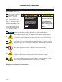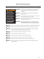
1
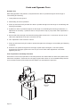
Service Manual for: UVL855R UVL855R24 Under-Vehicle Lift® Series 09 www.braunability.com/international ISO 9001:2008 631 West 11th Street, Winamac, IN 46996, USA Phone: +1 574 946 6153 Fax: +1 574 946 4670 37273 Rev. A February 2013 Original Instructions Congratulations We at The Braun Corporation wish to express our fullest appreciation on your new purchase. With you in mind, our skilled craftsmen have designed and assembled the finest lift available. This manual provides maintenance and service-related material. Braun UVL Series™ lifts are built for dependability and will provide years of pleasure and independence as long as the lift is properly maintained and operated by an instructed person. Sincerely, THE BRAUN CORPORATION Ralph W. Braun Chief Executive Officer Warranty Consult your local Braun dealer regarding warranty policy. www.braunlift.com/international The Braun Corporation® INDIANA, USA MODEL NUMBER Model No. XXXXXXXXXX SERIAL NUMBER Serial No. XX-XXXXX MFG DATE DatHRI0DQXIDFWXUH XX/XX/XXXX 6DPSOH6HULDO1R6HULHV1R,GHQWLÀFDWLRQ7DJ Serial No. Model No. OWNER'S WARRANTY REGISTRATION XXXXXXXXXX XX-XXXXX PURCHASED FROM OWNER DATE INSTALLED NAME ADDRESS CITY TELEPHONE STATE ZIP TO VALIDATE WARRANTY REGISTRATION CARDS MUST BE RETURNED TO THE BRAUN CORPORATION. Sample Warranty/Registration Card Contents Service Safety Precautions .......................................... 2-3 /LIW6SHFLÀFDWLRQV............................................................. 4 Lift Terminology ............................................................... 5 Switch and Sensor Locations .......................................... 6 Switch LED Diagnostics .................................................. 7 Carriage Adjustments ...................................................... 7 Floor Level and Bridge Plate Adjustments.................. 8-10 Static and Dynamic Tests ......................................... 11-12 Maintenance and Lubrication ................................... 13-17 Troubleshooting Diagnosis Chart ............................. 18-21 UVL855R (12V) Lift Electrical Schematic ...................... 22 UVL855R24 (24V) Lift Electrical Schematic .................. 23 Hydraulics Parts List ...................................................... 24 Hydraulics Diagram ....................................................... 25 UVL855R (12V) Pump Module Parts List ...................... 26 UVL855R (12V) Pump Module Diagram ....................... 27 UVL855R24 (24V) Pump Module Parts List .................. 28 UVL855R24 (24V) Pump Module Diagram ................... 29 Repair Parts List ............................................................ 30 Housing Detail ............................................................... 31 Carriage Detail............................................................... 32 Platform Detail ............................................................... 33 Declaration of Conformity - Machinery ..................... 34-35 Declaration of Noise Emission....................................... 36 Declaration of Conformity - EMC ................................... 37 Document Cross Reference Owner Manual 37272 Page 1 Service Safety Precautions Safety Symbols SAFETY FIRST! Know That.... The information contained in this manual and VXSSOHPHQWV LILQFOXGHG is provided for your use and safety. Familiarity with proper LQVWDOODWLRQRSHUDWLRQPDLQWHnance and service procedures LVQHFHVVDU\WRHQVXUHVDIH troublefree lift operation. Safety precautions are provided to LGHQWLI\SRWHQWLDOO\KD]DUGRXV situations and provide instruction on how to avoid them. A D NOTICE E 36513 B WARNING This symbol indicates important safety information regarding a potentially hazardous situation that could result in serious bodily injury and/or property damage. C CAUTION This symbol indicates important information regarding how to avoid a hazardous situation that could result in minor personal injury or property damage. $GGLWLRQDOLQIRUPDWLRQSURYLGHGWRKHOSFODULI\RUGHWDLODVSHFLÀFVXEMHFW This symbol indicates that there are dangerous high voltages present inside the HQFORVXUHRIWKLVSURGXFW7RUHGXFHWKHULVNRIÀUHRUHOHFWULFVKRFNGRQRWDWWHPSW to open the enclosure or gain access to areas where you are not instructed to do VR5HIHUVHUYLFLQJWRTXDOLÀHGVHUYLFHSHUVRQHORQO\ F This symbol indicates that a condition where damage to the equipment resulting injury could occur if operational procedures are not followed. To reduce the risk of GDPDJHRULQMXU\UHIHUWRDFFRPSDQ\LQJGRFXPHQWVIROORZDOOVWHSVRUSURFHGXUHV as instructed. G This symbol indicates an area to avoid bodily contact to prevent injury. 36514 H I This symbol indicates the presence of high pressure hydraulic hoses. Use appropriate personal protective equipment when working on hydraulic system. 7KLVV\PEROLQGLFDWHVWKHSUHVHQFHRIDÀUHKD]DUG$YRLGRSHQÁDPHVRUVSDUNV ZKHQZRUNLQJZLWKÁDPPDEOHPDWHULDOVWRSUHYHQWLQMXU\RUGDPDJH These symbols will appear throughout this manual as well as on the labels posted on your lift. Recognize the seriousness of this information. Page 2 Service Safety Precautions Service Safety Precautions WARNING If maintenance or repair procedures cannot be completed exactly as provided in this manual or if the instructions are not fully understood, contact The Braun Corporation immediately. Failure to do so may result in serious bodily injury and/ or property damage. WARNING 5HDGWKLVPDQXDOVXSSOHPHQW V DQGRSHUDWLQJLQVWUXFtions decals before performing operation or service procedures. WARNING Use appropriate personal protective equipment when servicing the lift. WARNING &KHFNIRUREVWUXFWLRQVVXFKDVJDVOLQHVZLUHVH[KDXVW etc. before drilling or cutting on vehicle. WARNING 5RXWHDOOFDEOHVFOHDURIH[KDXVWV\VWHPRWKHUKRWDUHDV PRYLQJSDUWVZHWDUHDVHWF WARNING 5LVNRIHOHFWULFDOVKRFNRUÀUH8VHH[WUDFDUHZKHQ making electrical connections. Connect and secure as outlined in Installation Instructions and Wiring Diagrams. WARNING $GMXVWYHKLFOHÁRRUOHYHOSRVLWLRQLQJRIEULGJHSODWHEHIRUHRSHUDWLQJOLIWZLWKSDVVHQJHU WARNING 0DLQWHQDQFHDQGUHSDLUVPXVWEHSHUIRUPHGRQO\E\DXWKRUL]HGVHUYLFHSHUVRQQHO WARNING 3HUIRUPPDLQWHQDQFHDQGOXEULFDWLRQSURFHGXUHVH[DFWO\DVRXWOLQHGLQWKH0DLQWHnance and Lubrication Schedule contained in this manual. WARNING Disconnect the power cable at the battery prior to servicing. WARNING Never modify (alter) a Braun Corporation lift. WARNING 5HSODFHPHQWSDUWVPXVWEH%UDXQDXWKRUL]HGUHSODFHPHQWV WARNING Never install screws or fasteners (other than factory equipped). WARNING :KHQHYHUUHSODFLQJDK\GUDXOLFF\OLQGHURUVHDOVORZHUSODWIRUPIXOO\ WARNING Failure to follow these safety precautions may result in serious bodily injury and/or property damage. Page 3 Lift Specifications 7KHOLIWPXVWEHLQVWDOOHGRSHUDWHGDQGPDLQWDLQHGDVGHWDLOHGLQDSSOLFDEOH manual. Any use of equipment other than instructed in this manual is prohibited. 7KH89/5DQG89/5KDYHFRPSOHWHGF\FOHVZLWKDNJ OE ORDGDQGDVWDWLF load test with a 1020 kg (2250 lb) load. Operating Temperature This equipment will operate in its intended ambient at a minimum between +5ºC and +40ºC. Relative Humidity 7KLVHTXLSPHQWZLOORSHUDWHFRUUHFWO\ZLWKLQDQHQYLURQPHQWDW5+DW& Altitude This equipment will operate correctly up to 1000m above mean sea level. Sound Pressure Level 7KHHPLVVLRQVRXQGSUHVVXUHOHYHODWWKHRSHUDWRUҋVSRVLWLRQLVH[SHFWHGQRWWRH[FHHGGE $ Transportation and Storage 7KLVHTXLSPHQWZLOOZLWKVWDQGRUKDVEHHQSURWHFWHGDJDLQVWWUDQVSRUWDWLRQDQGVWRUDJHWHPSHUDWXUHV RI&WR&DQGIRUVKRUWSHULRGVRIXSWR& 7KHOLIWKDVEHHQSDFNDJHGWRSUHYHQWGDPDJHIURPWKHHIIHFWVRIQRUPDOKXPLGLW\YLEUDWLRQDQGVKRFN Power Requirements 12 VDC -- UVL855R 24 VDC -- UVL855R24 Lift Weight (Installed) UVL855R -- 263 kg (580 lbs) UVL855R24 -- 263 kg (580 lbs) Lifting Capacity 0D[LPXPNJ OEV UV L VL UV R 55 L8 an 24 5R 85 85 5R a 88 dU m 4m 51 nd UV 9m L8 55 m R 24 63 mm Dimension from top of housing. Page 4 WARN ING Push manuaT-hand and lly le lock out movein fully to before Failure engagplatforand result to driving e platfor m in deployin lock uninteplatfor vehicle m platfor ment. nded m . result m may Uninte platfor and/orin deploy seriou nded m proper ment s may ty bodily damag injury Do not e. remo ve! 81823 = Center of Gravity Lift Terminology Lift Mounting Brackets (4) Hydraulic Cylinders Hand-Held Pendant Control Bridge Plate Lift Housing Lifting Arms LIFT UP N LIFT DOW STOW LIFT E DOOR CLOS 81812 Roll Stop Actuator Ca rria ge WARN ING Push manu T-han and ally dle lock out movein fully to Failurbefor engagplatfo and resulte to e drivine rm deplo in lock gplatfo in uninteplatfovehicrm platfoymen resultrm t. nded rm le. may and/o in deploUnint platfo seriouymenended rm r prope s t may rty bodily dama injury Do ge. not remo ve! 81823 Pump Module UV L Torque Tube P la tfo rm Platform Cable-activated Manual Release System Rolling +RUL]RQWDO$UPV Roll Stop Inboard Left Right Manual Folding Handrails Outboard Page 5 Switch and Sensor Locations Lift Out Limit Switch Lift Out Cam Full Out Limit Switch Full Out Cam Stow Start Limit Switch Floor Level Limit Switch Floor Level Cam Stow Start Cam LIFT UP LIFT DOWN STOW LIFT E DOOR CLOS 81812 WARN ING Push manuaT-hand and lly le lock out movein fully to before Failure engagplatforand result to driving e platfor m in deployin lock uninteplatfor vehiclm platfor ment. nded m e. result m may Uninte platfor and/orin deploy seriou nded m prope ment s may rty bodily damag injury Do not e. remo ve! 81823 UV L Roll Stop Limit Switch Pressure Switch Pressure Switch Page 6 Switch LED Diagnostics Lift Out Switch: The Lift Out Switch stops inward travel of the carriage/platform during Stow function (activated by the housing-mounted Lift Out Cam). Move cam in to increase inward travel. Move cam out to decrease inward travel. Diagnostic LED “LIFT OUT” will be illuminated when the switch is not contacting the cam. Full Out Switch: The Full Out Switch stops outward travel of the carriage/platform during Deploy (Up/Down) functions (activated by the housing-mounted Full Out Cam). Move cam in to decrease outward travel. Move cam out to increase outward travel. Carriage rollers must be inside housing a minimum 1.3 cm (1/2"). The platform will not raise or lower until this switch is activated. Diagnostic LED “FULL OUT” will be illuminated when the switch is contacting the cam. Floor Level Switch: Diagnostic LED “FL LVL” will be illuminated when the switch is contacting the cam. Detailed on page 8. Below Stow (Stow Start) Switch: The Below Stow Switch controls the height of the carriage/ platform before it moves inward during the Stow function (activated by the torque tube-mounted Stow Start Cam). Rotate the cam in to decrease platform height. Rotate the cam out to increase platform height. Adjust cam so bottom of platIRUPLVÁXVKZLWKWKHKRUL]RQWDODUPVZKHQ switch is activated. Diagnostic LED “BELOW” will be illuminated when platform is at stow start height or below. Carriage Adjustments 36514 Carriage Ride Height Adjustment Drive Chain Adjustment 7KHFDUULDJHKRUL]RQWDODUPVPRYH UROO LQDQG out of the housing tracks on roller bearings. )ROORZLQJLQVWDOODWLRQRUH[WHQVLYHOLIWRSHUDWLRQ FOHDUDQFHEHWZHHQKRUL]RQWDODUPVDQGWUDFNV may diminish. The eccentric shaft mounting plate allows height adjustment. In event the drive chain sags 1.3 cm (1/2") or PRUHDGMXVWWHQVLRQDVGHWDLOHG7LJKWHQWR eliminate visible sag but do not overtighten. Remove eccentric plate mounting screw. UsLQJVFUHZGULYHURUVPDOOURGURWDWHWKHVKDIW clockwise to increase carriage height. Rotate the shaft counterclockwise to decrease carriage height. Reinstall mounting screw in nearest retainer hole. Adjust left and right side eccentric shafts (screw positions may vary from side to VLGH $GMXVWKHLJKWVXFKWKDWKRUL]RQWDODUPVGR not contact top or bottom of tracks (align center). 1. Unlock and pull the manual release cable and lock in released position. 0DQXDOO\H[WHQGSODWIRUPFDUULDJHIXOORXW 3. Remove adjustment bolt (tensioner) access cover. 4. Use deep well socket (long key sleeve) to loosen outside jam nut. Tighten inside jam nut to eliminate visible chain sag but do not overtighten. 5. Lock jam nuts together. Unlock and push the manual cable in fully. Lock release cable. Move the platform in and out until platform chain release assembly engages chain. Access Cover Jam Nuts Figure A Tensioner WAR NING Pu sh ma T-h andnuallyandle loc out mo in full ve Faik bef to eng pla y and ore reslure to driage tform depult in loc vingplatfo in k rm pla loymeuninteplatfovehicle restform nt. nde rm . andult in dep Uninted pla may /or ser loyme ndetform pro iou nt d per s bod ma ty y dam ily inju Do age ry no . t rem ove! 81823 Manual Release Cable Page 7 Floor Level and Bridge Plate Adjustments 36514 $FKLHYLQJSURSHUÁRRUOHYHO positioning of the platform and bridge plate requires a combination of Floor Level switch adjustment and bridge plate adjustPHQW%RWKDUHIDFWRU\VHWEXW ÁRRUOHYHOSRVLWLRQLQJPXVWEH inspected during installation procedures (will vary per vehicle application). Floor Level Requirements: When the lift is positioned at ÁRRUOHYHO UDLVHGIXOO\ WKH bottom of the platform must be DERYHÁRRUOHYHODQGWKHEULGJH plate must rest solidly on vehicle ÁRRUZLWKDPLQLPXPRIFP (1.5") of overlap. Ensure the lift is positioned and VHFXUHGDVVSHFLÀHGLQWKHLQstructions supplied with the lift. Adjust the Floor Level switch ÀUVW (detailed below). If the bridge plate does not rest solLGO\RQYHKLFOHÁRRUDGMXVWWKH bridge plate cam as detailed in Cam Adjustment (adjust cam only if necessary). CAUTION Do not adjust bridge plate linkage rod. Linkage rod adjustment may result in lift damage. Do not adjust the bridge plate linkage rod (see Photo J on page 11). The linkage rod should be adjusted to increase usable platform length only (following all other procedures). Floor Level Switch Adjustment The Floor Level switch stops upward travel of the platform during the Up function (activated by the torque tube-mounted Floor Level cam). ,IEULGJHSODWHGRHVQRWUHVWRQÁRRUFRQWLQXHWRSXPSXSSODWIRUPWRDPD[LPXPRI FP DERYHÁRRUOHYHO OPEN OPEN Pump Handle OPEN CLOSE Figure B 2. Loosen the clamp securing the torque tubemounted Floor Level cam. See Photo A. Rotate the cam until the Floor Level switch is activated (cam depresses switch). Tighten the clamp securing the cam. Hand Pump OSE CL OSE CL 1. Position the bottom of the lift platform FP DERYHÁRRUOHYHOXVLQJWKH manual hand pump. See Figure B. Manual Hand Pump VALVE VALVE Floor Level Cam Valve Floor Level Switch A Hydraulic pressure may affect platform height slightly. Fine tuning adjustment (tweaking) of the Floor Level switch (cam) may be required. 8VLQJWKHFRQWUROSHQGDQW FKHFNÁRRUOHYHO position by lowering the platform to stow level and then pressing the UP button until the platform raises fully (stops). If the bridge plate rests solidly on vehicle ÁRRUDQGKDVDPLQLPXPRIFP RIYHKLFOHÁRRURYHUODS move to page 10 and check the usable platform length as outlined. 4. If the bridge plate does not rest on the veKLFOHÁRRU KRYHUVDERYHÁRRU DGMXVWWKH cam as detailed in the following section. Page 8 Torque Tube Cam depressing switch. Floor Level and Bridge Plate Adjustments Bridge Plate Cam Adjustment $GMXVWWKH)ORRU/HYHOVZLWFKÀUVW (detailed in previous section). If the above Floor Level Requirements are not met - adjust the bridge plate cam as detailed in the following procedures (lift in photos is not a UVL855R). Platform 12" above Stow Level Notice: Adjustment of the bridge plate cam affects the speed of bridge plate deployment and torque tube/vehicle clearance. B Stow Level 3RVLWLRQWKHOLIWSODWIRUPDSSUR[LPDWHO\ above stow level. See Photo B. Raising the platform will allow access to the cam securement screw and nut. See Photo C. 2. Use an Allen wrench to prevent the cam locking screw from turning and loosen the 3/8"VHUUDWHGÁDQJHQXWVHFXULQJWKHEULGJH plate cam. See Photos C and D. Do not remove the screw or nut. 8VLQJWKHFRQWUROSHQGDQW press the UP button until the platform raises fully (stops). 4. Turn the cam adjustment screw counterclockwise until the bridge plate rests on the YHKLFOHÁRRU6HH3KRWR' C Cam Locking Screw Cam Adjustment Screw 5. Verify there is no gap between the inner roll stop and the roll stop catch. See Photo E. Turn the adjustment screw clockwise to bring the bridge plate catch back in contact with the bridge plate. Do not remove the gap by adjusting the linkage rod. :KLOHKROGLQJWKHFDPORFNLQJVFUHZWLJKWHQWKHVHUUDWHGÁDQJHQXWVHFXUHO\ See Photos C and D. 9HULI\EULGJHSODWHRYHUODSVYHKLFOHÁRRUD minimum of 3.8 cm (1 1/2"). Adjust full out cam and/or lift housing positioning to meet this requirement. D 3/8" Serrated Flange Nut Bridge Plate Catch Bridge Plate Linkage Rod E Page 9 Floor Level and Bridge Plate Adjustments Usable Platform Length CAUTION Improper bridge plate linkage rod adjustment may result in lift damage. Do not adjust the bridge plate linkage rod unless H[WUD usable platform length is needed. See Photo F. Linkage rod adjustment affects angle of bridge plate (vertical position). If the angle of the bridge plate (when in the vertical position) restricts the usable platform OHQJWKIRUWKHZKHHOFKDLUSDVVHQJHUDGMXVWment of the linkage rod will change the angle. Adjust the bridge plate as detailed in the previRXVSURFHGXUHV7KHQDGMXVWWKHOLQNDJHURG as detailed (only if necessary). If the linkage URGLVRYHUDGMXVWHG WRRORQJRUWRRVKRUW LW ZLOOH[FHHGWKHWUDYHORIWKHVOLGHUEORFNUHVXOWLQJLQGDPDJHWRWKHFDPIROORZHUEHDULQJWKH cam and/or other components. F Bridge Plate Linkage Rod Adjustment 1. Position the lift platform below stow level using the manual hand pump (turn valve counterclockwise). Do not operate the lift with the electric pump during adjustment procedures. 2. Loosen the jam nuts at each end of the linkage rod. Adjust rod length DVQHHGHG0LQLPL]HDGMXVWPHQW Provide a minimum of 1" clearance between bridge plate and torque tube (bridge plate must clear cylinder mount). See Photo H. 3. Carefully check the bridge plate angle and operation using the hand pump. Ensure the linkage rod has not been over adjusted resulting in pressure on components (damage will result). G Linkage Rod Torque Tube 1" Minimum Clearance 4. Tighten the linkage rod jam nuts. H Page 10 Static and Dynamic Tests Compatibility between the lift and the vehicle 7KHLQVWDOOHUVKDOOFRQÀUPWKHFRPSDWLELOLW\EHWZHHQWKHOLIWDQGWKHYHKLFOH Static Test Deformation 7KHXQODGHQSODWIRUPLVSRVLWLRQHGPLGZD\EHWZHHQJURXQGOHYHODQGYHKLFOHÁRRUOHYHODQG PHDVXUHPHQWVDUHWDNHQRIWKHKHLJKWRIWKHSODWIRUPDQGLWVDQJXODUDWWLWXGHUHODWLYHWRWKHYHKLFOHÁRRU A load of 425k is applied to the platform and subsequently removed. %\UHSHDWLQJPHDVXUHPHQWVRIWKHKHLJKWDQGDWWLWXGHRIWKHSODWIRUPYHULI\WKDWQRSHUPDQHQW deformation has occurred in any part of the lift or its attachment to the vehicle which could affect the function of the lift. Drift $ORDGRINJLVDSSOLHGWRWKHSODWIRUPSRVLWLRQHGDWÁRRUOHYHO0HDVXUHPHQWVDUHWDNHQRIWKH KHLJKWRIWKHSODWIRUPDQGLWVDQJXODUDWWLWXGHUHODWLYHWRWKHYHKLFOHÁRRU7KHVHPHDVXUHPHQWVDUH repeated after a 15 minute test period. 9HULI\WKDWWKHYHUWLFDOGULIWRIWKHSODWIRUPEHWZHHQWKHWZRPHDVXUHPHQWVKDVQRWH[FHHGHGPP 9HULI\WKDWWKHDQJXODUGULIWRIWKHSODWIRUPEHWZHHQWKHWZRPHDVXUHPHQWVKDVQRWH[FHHGHG If lift does drift: 1. Deploy lift to ground level. 2. Press circuit board manual override buttons L-UP and L-DN for 20 seconds. 3. Open manual down valve 1 turn and press “UP” on hand pendant for 20 seconds. Close valve. Test to Verify that the Lift Cannot Lift Excessive Load $ORDGRINJLVDSSOLHGWRWKHSODWIRUPSRVLWLRQHGDWJURXQGOHYHO$FWXDWHWKH´83µFRQWURODQG verify that the platform does not lift (tilt is permissible). 1. Lower platform to the ground. 2. Place 425kg at center of platform. 3. Press up switch and verify platform does not lift (tilt is permissible). ,ISODWIRUPGRHVQRWOLIWSURFHHGWR'\QDPLF7HVW,ISODWIRUPGRHVOLIWSURFHHGWRVWHSSXPSUHOLHI valve adjustment is necessary. $FFHVVUHOLHIYDOYHWKURXJKFLUFXLWERDUGPRXQWLQJSODWHDFFHVVKROH/RRVHQKH[QXWRQWKH UHOLHIYDOYHDGMXVWPHQWVFUHZ GRQRWUHPRYHKH[QXW 6. Turn adjustment screw counterclockwise1/8 turn. 7. Press up switch and verify platform does not lift (tilt is permissible). ,ISODWIRUPGRHVQRWOLIWWLJKWHQKH[QXW GRQRWWXUQUHOLHIYDOYHDGMXVWPHQWVFUHZZKLOH WLJKWHQLQJKH[QXW ,ISODWIRUPGRHVOLIWUHSHDWVWHSVWKURXJK Page 11 Static and Dynamic Tests Dynamic Test :LWKNJDSSOLHGWRWKHSODWIRUPYHULI\WKDWWKHOLIWLVDEOHWRRSHUDWHWKURXJKRXWLWVIXOOUDQJHRI normal lifting and lowering. 1. Lower platform to the ground. 2. Place 340kg at center of platform. 3. Press up switch and verify that the lift is able to operate throughout its full range of normal lifting and lowering movements. ,ISODWIRUPLVDEOHWRRSHUDWHWKURXJKRXWLWVIXOOUDQJHRIQRUPDOOLIWLQJDQGORZHULQJPRYHPHQWVQR DGMXVWPHQWLVQHFHVVDU\,ISODWIRUPGRHVQRWOLIWSURFHHGWRVWHSSXPSUHOLHIYDOYHDGMXVWPHQWLV necessary. $FFHVVUHOLHIYDOYHWKURXJKFLUFXLWERDUGPRXQWLQJSODWHDFFHVVKROH/RRVHQKH[QXWRQWKH UHOLHIYDOYHDGMXVWPHQWVFUHZ GRQRWUHPRYHKH[QXW 6. Turn adjustment screw clockwise 1/8 turn. 7. Press up switch and verify lift is able to operate throughout its full range of normal lifting and lowering movement. ,IOLIWGRHVQRWRSHUDWHWKURXJKRXWLWVIXOOUDQJHUHSHDWVWHSVWKURXJK,IOLIWGRHVRSHUDWH WKURXJKRXWLWVIXOOUDQJHWLJKWHQKH[QXW GRQRWWXUQUHOLHIYDOYHDGMXVWPHQWVFUHZZKLOH WLJKWHQLQJKH[QXW Test of Operations and Safety Functions $OOIXQFWLRQVRIWKHOLIWDQGRSHUDWLRQVRIDOOVDIHW\GHYLFHVDUHYHULÀHGDIWHUWKHVWDWLFDQGG\QDPLFWHVWV have been completed. These tests do not apply to pipe break valves nor non-resettable safety devices such as electrical fuses (These items are the subject of a manufacturer’s type test). Relief Valve Adjustment Screw Page 12 9/16" +H[1XW Maintenance and Lubrication 36513 36514 3URSHUPDLQWHQDQFHLVQHFHVVDU\WRHQVXUHVDIH trouble-free lift operation. Inspecting the lift for DQ\ZHDUGDPDJHRURWKHUDEQRUPDOFRQGLWLRQV should be a part of the transit agency daily service program. Simple inspections can detect potential problems. 3DUNYHKLFOHRQDOHYHOVXUIDFHFOHDURIWUDIÀFDQG bystanders. Place vehicle transmission in “Park” and engage parking brake. Deploy lift to ground level. Provide adequate work space around fullyGHSOR\HGOLIW3HUIRUPVSHFLÀHGPDLQWHQDQFHDQG lubrication procedures (position lift as required). 3XPS0RGXOH:KHQFOHDQLQJWKHH[WHULRURI WKHSXPSPRGXOHÀUVWGLVFRQQHFWWKHXQLWIURP LWVSRZHUVRXUFH'RQRWXVHOLTXLGFOHDQHUV DHURVROVDEUDVLYHSDGVVFRXULQJSRZGHUVRU VROYHQWVVXFKDVEHQ]LQHRUDOFRKRO8VHD soft cloth lightly moistened with a mild detergent solution. Ensure the surface cleaned is fully dry before reconnecting power. Other Components: Clean components and the surrounding area before applying lubricants. Clean only with mild detergent and water. Do not clean with solvents. Allow the lift to dry thoroughly DQGDSSO\OXEULFDQWVDVVSHFLÀHGDIWHUHYHU\ cleaning. LPS2 General Purpose Penetrating Oil is recommended where Light Oil is called out. Use of improper lubricants can attract dirt or other contaminants which could result in wear or damage to components. Platform components H[SRVHGWRFRQWDPLnants when lowered to the ground may UHTXLUHH[WUDDWWHQtion. WARNING Maintenance and lubrication procedures must be performed as VSHFLÀHGE\DQ authorized service technician. Failure to do so may result in serious bodily injury and/or property damage. Perform maintenance and lubrication procedures at the scheduled intervals according to the number of cycles. When servicing the OLIWDWWKHUHFRPPHQGHGLQWHUYDOVLQVSHFWLRQDQG OXEULFDWLRQSURFHGXUHVVSHFLÀHGLQWKHSUHYLRXV sections should be repeated. These intervals are a general guideline for scheduling maintenance procedures and will vary acFRUGLQJWROLIWXVHDQGFRQGLWLRQV/LIWVH[SRVHGWR VHYHUHFRQGLWLRQV ZHDWKHUHQYLURQPHQWFRQWDPLQDWLRQKHDY\XVDJHHWF PD\UHTXLUHLQVSHFWLRQ and maintenance procedures to be performed PRUHRIWHQWKDQVSHFLÀHG Records of maintainence and service procedures should be maintained. Discontinue lift use if maintenance and lubrication SURFHGXUHVDUHQRWSURSHUO\SHUIRUPHGRULIWKHUH LVDQ\VLJQRIZHDUGDPDJHRULPSURSHURSHUDWLRQ&RQWDFW\RXUDXWKRUL]HGUHSUHVHQWDWLYH Page 13 Maintenance and Lubrication Lubrication Diagram Drive Chain and Rollers LO Drive Chain Release Latch SG Eccentric Shaft Rollers (bearings) LO Hydraulic Cylinder Pivot Points LO LIFT UP LIFT DOWN STOW LIFT E DOOR CLOS Hydraulic Cylinder Pivot Points LO 81812 Torque Tube Pivot Points LO Lifting Arm Pivot Points Rolling LO Horizontal Carriage Tube Eccentric Slot Area Shaft and DE Carriage Rollers (bearings) LO WAR NIN G Platform Cable-activated Manual Release System Push manu T-han and ally dle lock out movein fully to Failurbefore engagplatfo and resulte to drivine rm deplo in lock gplatfo in uninteplatfovehicrm platfoymen resultrm t. nded rm le. may and/o in deploUnint platfo seriouymenended rm r prope s t may rty bodily dama injury Do ge. not remo ve! 81823 Torque Tube Pivot Points LO UV L Roll Stop Detent Pin LO Lifting Arm Pivot Points LO Bridge Plate Linkage Pivot Points LO Bridge Plate Hinge Pivot Points LO Eccentric Shaft and Carriage Rollers (bearings) LO Roll Stop and Lower Closure Pivot Points LO See the Maintenance/Lubrication Schedule for recommended applications per number of cycles. Lubricant Type 6SHFLÀHG UHFRPPHQGHG Lubricant /LJKW3HQHWUDWLQJ2LO /36*HQHUDO3XUSRVH (30 weight or equivalent) Penetrating Oil 6WDLQOHVV6WLFN 'RRU(DVH DE - Door-Ease Style (tube) Stick (tube) 6\QWKHWLF*UHDVH 0RELOWHPS6+& SG - Synthetic Grease (Multipurpose) LO - Light Oil Page 14 $YDLODEOH Amount R] Aerosol Can R] R] Tube %UDXQ Part No. 15807 15806 28598 Maintenance and Lubrication 750 Cycles Roll stop and lower closure pivot points (2) Apply Light Oil - See Lubrication Diagram Inspect roll stop and lower closure for proper operation Correct or replace damaged parts. Inspect lower closure gasket 5HVHFXUHUHSODFHRUFRUUHFWDVQHHGHG Roll stop detent pin Apply Light Oil - See Lubrication Diagram Roll stop latch spring 5HVHFXUHUHSODFHRUFRUUHFWDVQHHGHG Bridge plate hinge pivot points Apply Light Oil - See Lubrication Diagram Bridge plate linkage pivot points Apply Light Oil - See Lubrication Diagram Lifting arm pivot points and rollers (bearings) Apply Light Oil - See Lubrication Diagram ,QVSHFWOLIWIRUZHDUGDPDJHRUDQ\ abnormal condition Correct as needed. Inspect lift for rattles Correct as needed. Check drive chain tension. Pull out and lock manual release cable. Adjust chain tension as needed. See Drive Chain Adjustment. Inspect bridge plate and linkage for: 3URSHURSHUDWLRQ 3RVLWLYHVHFXUHPHQW :HDURUGDPDJH 3URSHUDGMXVWPHQW 5HVHFXUHUHSODFHRUFRUUHFWDVQHHGHG See Floor Level and Bridge Plate Adjustment Instructions. Check carriage ride height in housing Adjust as needed. See Carriage Ride Height Adjustment. Check stow height/lifting arm alignment /LIWLQJDUPVVKRXOGEHKRUL]RQWDO aligned with each other and aligned with carriage. Adjust as needed. See Below Stow Switch. Inspect wiring harnesses for VHFXUHPHQWZHDURURWKHUGDPDJH 5HVHFXUHUHSODFHRUFRUUHFWDVQHHGHG Check lower pan securement 5HVHFXUHUHSODFHGDPDJHGSDUWVRU correct as needed. Torque tube pivot points (6 places) Apply Light Oil - See Lubrication Diagram Page 15 Maintenance and Lubrication 1500 Cycles Page 16 Carriage rollers (bearings) Apply Light Oil - See Lubrication Diagram Eccentric shaft rollers (bearings) Apply Light Oil - See Lubrication Diagram 5ROOLQJKRUL]RQWDOFDUULDJHWXEHVORW area Apply Door-Ease - See Lubrication Diagram. Apply to the surface area DURXQGERWKVORWVDQGZLSHRIIH[FHVV Hydraulic cylinder pivot points (4 per cylinder) Apply Light Oil - See Lubrication Diagram Drive chain and chain rollers Apply Light Oil - See Lubrication Diagram Drive chain release latch mechanism Apply Synthetic Grease - See Lubrication Diagram 'HSOR\OLIWUHPRYHXSSHUSDQDQGEORZ out housing and clean housing tracks. 8VHFRPSUHVVRUDQGQR]]OHWRUHPRYH all debris from housing. Use clean cloth and solvent to clean tracks. &KHFNGULYHFKDLQWHQVLRQHUMDPQXWV and connecting link for securement and/or misalignment. Correct or replace damaged parts and/or relubricate. See Drive Chain Adjustment. Inspect drive chain release latch PHFKDQLVPIRUSURSHURSHUDWLRQ SRVLWLYHVHFXUHPHQWZHDURURWKHU damage. Correct or replace damaged parts and/ or relubricate. Inspect platform cable-activated manual release system (T-handle/cable assembly and carriage movement). Ensure T-handle release and cable assembly operate properly. Ensure FDUULDJHFDQEHPDQXDOO\H[WHQGHGDQG retracted freely. Inspect limit switches and cams for securement and proper adjustment 5HVHFXUHUHSODFHRUDGMXVWDVQHHGHG See Switch Adjustment. ,QVSHFWFDUULDJHOLIWLQJDUPDQG eccentric shaft rollers (bearings) for ZHDURUGDPDJHSRVLWLYHVHFXUHPHQW and proper operation 5HVHFXUHUHSODFHRUFRUUHFWDVQHHGHG ,QVSHFWH[WHUQDOVQDSULQJV HFOLSV &DUULDJHUROOHUEHDULQJV /RZHUOLIWLQJDUPSLQV %ULGJHSODWHSLYRWSLQ (FFHQWULFVKDIWWUDFNUROOHU bearing (4) +DQGUDLOSLYRWSLQV 5ROOVWRSDFWXDWRU +\GUDXOLFF\OLQGHUSLQV 5HVHFXUHUHSODFHGDPDJHGSDUWV lubricate or correct as needed. Inspect lower lifting arm pins for wear RUGDPDJHSRVLWLYHVHFXUHPHQWDQG proper adjustment 5HVHFXUHUHSODFHGDPDJHGSDUWV lubricate or correct as needed. See Carriage Ride Height Adjustment. Maintenance and Lubrication 1500 Cycles 4500 Cycles Consecutive 750 Cycle Intervals Lift Disposal Procedure ,QVSHFWHFFHQWULFVKDIWSLQVEHDULQJ PRXQWLQJVFUHZZDVKHUVDQG securement hardware for wear or GDPDJHSRVLWLYHVHFXUHPHQWDQG proper operation 5HVHFXUHUHSODFHRUFRUUHFWDVQHHGHG Inspect torque tube cams for VHFXUHPHQWZHDURUGDPDJH 5HVHFXUHUHSODFHRUFRUUHFWDVQHHGHG Inspect housing cam brackets for VHFXUHPHQWZHDURUGDPDJH 7LJKWHQUHSDLURUUHSODFHLIQHHGHG ,QVSHFWF\OLQGHU V KRVHVÀWWLQJVDQG K\GUDXOLFFRQQHFWLRQVIRUZHDUGDPDJH or leaks 5HVHFXUHUHSDLURUUHSODFHLIQHHGHG Inspect power cable 5HVHFXUHUHSDLURUUHSODFHLIQHHGHG Inspect handrails for securement 5HVHFXUHUHSDLURUUHSODFHLIQHHGHG Hydraulic Fluid (Pump) - Check level. Notice: Fluid should be changed if there is visible contamination. Inspect WKHK\GUDXOLFV\VWHP F\OLQGHUKRVHV ÀWWLQJVVHDOVHWF IRUOHDNVLIÁXLGOHYHO is low. 8VHDYLDWLRQÁXLGRQO\ SDUW 5 'RQRWPL[ZLWK'H[WURQ,,, RURWKHUK\GUDXOLFÁXLGV&KHFNÁXLG level with platform lowered fully. Fill WRPD[LPXPÁXLGOHYHOLQGLFDWHGRQ UHVHUYLRU VSHFLÀHGRQGHFDO 'RQRW RYHUÀOO,IÁXLGOHYHOGHFDOLVQRWSUHVHQW - measure 22 mm (7/8") from the bottom RIWKHÀOOWXEHWRORFDWHÁXLGOHYHO Inspect lifting arm bushings and pivot pins for visible wear or damage Replace if needed. Inspect roll stop pivot pin mounting bolts (2) Tighten or replace if needed Mounting Check to see that the lift is securely anchored to the vehicle and there are QRORRVHEROWVEURNHQZHOGVRUVWUHVV fractures. Decals and Antiskid 5HSODFHGHFDOVLIZRUQPLVVLQJRU illegible. Replace antiskid if worn or missing. 5HSHDWDOOSUHYLRXVO\OLVWHGLQVSHFWLRQ lubrication and maintenance procedures at 750 cycle intervals. 5HWXUQOLIWWRDQDXWKRUL]HGGHDOHUIRUGUDLQLQJRIWKHK\GUDXOLFV\VWHP 2. Transport lift to a recycling center for recycling. Page 17 Troubleshooting Diagnosis Chart 36513 36514 WARNING Troubleshooting and repair procedures must be performed DVVSHFLÀHGE\DXthorized service personnel only. Failure to do so may result in serious bodily injury and/or property damage. FUNCTION 1.00 NO OPERATION 2.00 PUMP RUNS BUT WILL NOT LIFT PLATFORM Page 18 If a problem occurs with your OLIWGLVFRQWLQXHRSHUDWLRQLPPHGLDWHO\'RQRWDWWHPSWUHSDLUV yourself. Contact your sales representative. The cause of the problem can be determined by locating the lift function and related symptom in the Troubleshooting Diagnosis Charts. The VSHFLÀFFDXVHDQGUHPHG\FDQ then be determined by process of elimination. A Electrical Schematic and Hydraulic Diagram are provided to aid in troubleshooting. $5HSDLU3DUWVVHFWLRQZLWKH[ploded views and corresponding parts lists is also provided. Correct the problem if possible. If the SUREOHPFRQWLQXHVFRQWDFW\RXU sales representative. POSSIBLE CAUSE REMEDY 1.11 Low Battery Vehicle engine must be running during lift operation. Check condition of vehicle battery. 1.12 Bad ground Check for good ground between vehicle chas sis and aluminum manifold on power pack. 1.13 Poor plug connections Check all plugs for proper contact. 1.14 Blown fuse Check inline fuse on “24 V” wire from P.C. board. Check P.C. board mounted fuse. Check for power on terminal 8 of terminal block on P.C. board. 1.15 Defective circuit breaker Reset or replace if necessary. 1.16 Improper terminal block wiring Check for proper wiring of terminal block. 2.11 Hydraulic valve open Flush valve by operating manual override switches UP and DOWN at same time for 4 to 5 seconds several times. 2.12 Manual valve open Close manual valve. Flush valve by running UP with manual override. Open valve 4 to 5 seconds several times. 3XPSPRXQWHGKRUL]RQWDO Power pack must be mounted vertically. 2.14 No oil (low) &KHFNÁXLGOHYHO 2.15 Hydraulic hose not connected Check hose connection between pump and cassette. Troubleshooting Diagnosis Chart FUNCTION 3.00 PUMP DOES NOT RUN WITH MANUAL OVERRIDE OR HAND-HELD PENDANT 4.00 LIFT WILL GO UP WITH OVERRIDE SWITCH BUT NOT WITH HAND-HELD PENDANT 5.00 LIFT WILL NOT GO DOWN WITH MANUAL OVERRIDE OR WITH HAND-HELD PENDANT OR GOES DOWN SLOWLY OR DRIFTS DOWN BY ITSELF 6.00 LIFT WILL GO DOWN WITH OVERRIDE BUT NOT WITH HAND-HELD PENDANT 7.00 LIFT WILL NOT GO OUT WITH OVERRIDE OR HAND-HELD PENDANT POSSIBLE CAUSE REMEDY 3.11 Up Solenoid Check for power on pump “T” wire going to solenoid. 3.12 Bad power and ground See 1.00 4.11 FULL OUT diagnostic LED not illuminated Check full out switch for proper operation/adjustment. Replace or adjust as necessary. 4.12 Hand-held pendant not working properly Check for UP diagnostic LED when hitting UP EXWWRQRQKDQGFRQWURO5HSODFHFRQWUROER[DV necessary. 4.13 See 12.0 5.11 Hydraulic down valve bad Check for power on valve ”T” wire going to solenoid when pushing manual override or remote button. Replace if necessary. 5.12 Dirty down valve (clogged) Flush valve by pushing manual override up and down buttons at same time for 4 to 5 seconds several times. 6.11 FULL OUT diagnostic LED not illuminated. Check for proper operation of Full Out switch with diagnostic LED. Replace or adjust switch as necessary. 6.12 See 12.0 7.11 Defective circuit breaker Reset or replace if necessary. 7.12 No power on terminal 8 Check vehicle door full open switch and wiring. 7.13 Interlock circuit incomplete Verify interlock installation 7.14 Poor plug connections &KHFNKDUQHVVFRQQHFWLRQV((%DQG% 7.15 Bad in/out motor Check power at motor. Replace motor if necessary. 7.16 Bad power and ground See 1.00 Page 19 Troubleshooting Diagnosis Chart FUNCTION POSSIBLE CAUSE REMEDY 8.00 LIFT WILL NOT STOW WITH HAND-HELD PENDANT 8.11 Faulty Below Stow switch. BELOW STOW (BELOW) diagnostic LED not illuminated 9.00 ROLL STOP WILL NOT OPERATE UP OR DOWN WITH HAND-HELD PENDANT OR OVERRIDES 9.11 Ground Sensor pressure switch 9.13 Hydraulic poppet valve bad Check for power on “BAR DN” wire going to solenoid when pushing manual override or remote button while platform is on the ground. Replace if necessary. Notice: Down and Barrier Down override switches must be pressed at same time to lower roll stop. 9.14 Dirty poppet valve (clogged) Replace 9.11 Defective circuit breaker Reset or replace if necessary. 9.13 Bad relay(s) Check Barrier Up and Barrier Down power relays. Replace if necessary. 10.11 Hand-held pendant not working properly Check for UP diagnostic LED when hitting UP EXWWRQRQKDQGFRQWURO5HSODFHFRQWUROER[DV necessary. 10.00 ROLL STOP OPERATES WITH OVERRIDES BUT WILL NOT GO UP WITH HAND-HELD PENDANT 11.00 ROLL STOP OPERATES WITH OVERRIDES BUT WILL NOT GO DOWN WITH HAND-HELD PENDANT 12.00 SWITCHES DO NOT ACTIVATE LED(S) Page 20 Check for proper operation of Below Stow switch. Replace or adjust switch as necessary. 8.12 See 12.0 Reset or replace if necessary. 9.12 See 5.0 10.12 See 12.0 11.11 GROUND SENSOR (GND SENS) diagnostic LED not illuminated Check Ground Sensor pressure transducer. Replace or adjust as necessary. 11.12 BELOW STOW (BELOW) diagnostic LED not illuminated Check Below Stow switch for proper operation. Replace or adjust as necessary. 11.13 FULL OUT diagnostic LED not illuminated Check Full Out switch for proper operation. Replace or adjust as needed. 11.14 See 12.0 12.11 Improper terminal block wiring &KHFNWHUPLQDOEORFNIRUFRUUHFWZLULQJFRQÀJXration. 12.12 No power going to switches &KHFNSRZHURQFRQQHFWRU$SLQVDQG 12.13 Faulty wiring Check continuity of wires from switches to connector A2. 12.14 Faulty connections Check for proper connections on each switch and on each connector on the harnesses. Replace contact if necessary. See diagram at right. Troubleshooting Diagnosis Chart 13.00 DOORS DO NOT OPEN 13.11 Faulty wiring Check for proper wiring to door openers. CONTACT REMOVAL 1. Remove orange wedge using needle nose pliers or a hook shaped wire to pull wedge straight out. 7RUHPRYHWKHFRQWDFWVJHQWO\ SXOOZLUHEDFNZDUGVZKLOHDW the same time releasing the lock LQJÀQJHUE\PRYLQJLWDZD\IURP the contact with a screwdriver. +ROGWKHUHDUVHDOLQSODFHDV removing the contact will displace the seal Page 21 Page 22 UVL855R (12V) Lift Electrical Schematic DOOR CLOSE SWITCH PRESSURE SWITCH NO NO C RD / WH-1.31-16 GN / WH-1.31-16 BU / WH-1.31-16 BK / RD-1.31-16 NOT USED NOT USED NOT USED NOT USED WH / RD-1.31-16 OR / RD-1.31-16 BU / RD-1.31-16 RD / GN-1.31-16 RD / WH-1.31-16 GN / WH-1.31-16 BU / WH-1.31-16 BK / RD-1.31-16 WH / RD-1.31-16 OR / RD-1.31-16 BU / RD-1.31-16 RD / GN-1.31-16 POWER PACK / LIFT HOUSING HARNESS #73910A-800 RD BAR DN SW PWR A B C NOT USED OR-0.823-18 BU-0.823-18 A B C A B C RD BK BK-0.326-22 RD-0.326-22 RD-0.823-18 GND VALVE T PUMP T 12V A1 1 2 3 4 5 6 7 8 9 10 11 12 UVL REMOTE CONTROL CIRCUIT BREAKER (Manual Reset) 15A Q1 DESCRIPTION DOWN SOLENOID BU-0.518-20 BAT. WH-3.31-12 1 2 3 4 5 6 FRAME GROUND 1 2 3 4 5 6 CIRCUIT BREAKER P1 CONNECTORS JUNCTION GROUND MOTOR SOLENOID V1 V2 BU-1.31-16 WH-3.31-12 GROUND WH-3.31-12 STOW CU-0.518-20 CU-0.518-20 DOWN UP WH-0.823-18 BK-0.823-18 OR-0.823-18 GN-0.823-18 RD-0.823-18 NO RELAY SOLENOID 86 85 87 30 87A Y2 RD-33.6-2 HYDRAULIC PUMP MOTOR SOLENOID OR RELAY BK-33.6-2 M1 NO C GROUND MICROSWITCH NOTICE: 5 CIRCUIT BREAKER FUSE NC NOTICE 1) JUNCTIONS ONLY OCCUR AT MARKED INTERSECTIONS. BK BK-13.3-6 M SWITCH NC WH BK-13.3-6 MOTOR M C BK GROUND Y1 SYMBOL A B C GN-1.31-16 OR-1.31-16 BK-1.31-16 F2 5A P2 BAR DN S10 BK-3.31-12 OR-1.31-16 FUSE AUX. A2 CLOSE BK M BK-3.31-12 OR-1.31-16 BU-1.31-16 RD-3.31-12 WH-3.31-12 OR-1.31-16 GND VALVE T PUMP T 12V 12V PWR 80A RD-33.6-2 DIODE RD-33.6-2 AUX. Q2 BAT. 2) ALL WIRES AND COMPONENTS OPERATE AT 12 VOLTS DC. N2 WH RD BK WH RD BK 3) WIRE IDENTIFICATION: WIRE COLOR - WIRE SIZE IN MM2 - WIRE SIZE IN AWG 4) A LIFT ON/OFF POWER SWITCH MUST BE INSTALLED. USE BRAUN SWITCH #36678KS OR CE EQUIVALENT. BLACK JUMPER WIRE MUST BE REMOVED FROM SOCKETS 8 AND 11 WHEN INSTALLING POWER SWITCH CIRCUIT. 5) A 80A CIRCUIT BREAKER MUST BE INSTALLED. USE BRAUN CIRCUIT BREAKER #85804A OR CE EQUIVALENT. 6) AN E-STOP SWITCH WITH 3A INLINE FUSE MUST BE INSTALLED. USE BRAUN E-STOP SWITCH KIT #36679KS OR CE EQUIVALENT. Use caution when working on components inside pump module. An available energy level of over 240 VA creates an energy hazard. BATTERY POSITIVE TERMINAL (12V) BU-0.518-20 Q1 RD-0.823-18 NOT USED BK-0.823-18 NOT USED NOT USED YL / RD-0.823-18 GN / RD-0.823-18 NOT USED NOT USED TN-0.823-18 VT-0.823-18 WH / TN-0.823-18 K7 BU-1.31-16 C1 K6 VALVE T K5 OR-1.31-16 K4 RD-3.31-12 I P G F O R PUMP T HC PWR HC UP HC DOWN HC STOW HC CLOSE HC GND WH-1.31-16 WH-1.31-16 WH-1.31-16 WH-1.31-16 WH-1.31-16 WH-1.31-16 WH-1.31-16 WH-1.31-16 BU-1.31-16 RD-1.31-16 GN-1.31-16 OR-1.31-16 BK-1.31-16 1 2 3 4 5 6 C2 GN-1.31-16 OR-1.31-16 RD-1.31-16 M3 O2 1 2 N1 F1 1 2 3 4 5 6 CU-0.518-20 SAFETY GND SENS FULL OUT NOT FULL OUT BELOW STOW 1 2 RD-0.823-18 B1 BK-1.31-16 BARRIER ACTUATOR MOTOR RD-0.823-18 BK-0.823-18 E-STOP SWITCH BK-0.823-18 BU-1.31-16 M1 NOT USED RD-1.31-16 BK-1.31-16 L1 RD BAR UP PWR BAR DN PWR F3 S6 WIRED HAND-HELD CONTROL #73946A-100-1 BU / BK-1.31-16 OR / BK-1.31-16 GN / BK-1.31-16 GN-1.31-16 OR-1.31-16 RD-1.31-16 3A WH-1.31-16 RD-1.31-16 WH-1.31-16 BK-1.31-16 WH-1.31-16 RD-1.31-16 BK-1.31-16 WH-1.31-16 BK-1.31-16 RD-1.31-16 WH-1.31-16 RD-1.31-16 BK-1.31-16 M2 A B C K1 BK-1.31-16 O1 RD-0.823-18 BK-0.823-18 OR-0.823-18 BU-0.823-18 L2 WH RD BK 1 2 3 4 S5 WH-1.31-16 WH-1.31-16 WH-1.31-16 WH-1.31-16 WH-1.31-16 WH-1.31-16 BK / WH-1.31-16 F2 1 2 3 4 RD-0.823-18 BK-0.823-18 A B C OR / BK-1.31-16 NOT USED BK-1.31-16 BK / WH-1.31-16 NOT USED BK-1.31-16 BK-1.31-16 CARRIAGE / PLATFORM HARNESS #75930A RD / WH-1.31-16 GN / WH-1.31-16 RD / BK-1.31-16 BK-1.31-16 A B C J1 NOT USED GN / BK-1.31-16 BK-1.31-16 I1 BU / BK-1.31-16 NOT USED BK-1.31-16 H1 A B C A B C A B C A B C A B C A B C NOT USED BU-1.31-16 WH-1.31-16 BK-1.31-16 RD / BK-1.31-16 GN / WH-1.31-16 RD / WH-1.31-16 RD-1.31-16 GN-1.31-16 OR-1.31-16 BU-1.31-16 GN / BK-1.31-16 OR / BK-1.31-16 BU / BK-1.31-16 BK / W-1.31-16 BK-1.31-16 WH-1.31-16 SW PWR BAR DN BAR DN PWR BAR UP PWR K2 H2 G1 S4 A B C G2 IGN PWR SW PWR LIFT OUT FLOOR LVL FLOOR IN SAFETY GND SENS FULL OUT NOT FULL OUT BELOW STOW S3 NC NC NC GN-0.823-18 NC RD-0.823-18 GN-0.823-18 BK-0.823-18 RD-1.31-16 BK-1.31-16 S2 WH-1.31-16 RD-1.31-16 BK-1.31-16 WH-1.31-16 BK-1.31-16 RD-1.31-16 WH-1.31-16 RD-1.31-16 BK-1.31-16 BK-1.31-16 RD / BK-1.31-16 GN / WH-1.31-16 RD / WH-1.31-16 RD-1.31-16 GN-1.31-16 OR-1.31-16 BU-1.31-16 GN / BK-1.31-16 OR / BK-1.31-16 BU / BK-1.31-16 BK / WH-1.31-16 BK-1.31-16 WH-1.31-16 NC C C C C S1 NO NO NO NO WH-1.31-16 SW PWR BAR DN BAR DN PWR BAR UP PWR BELOW STOW FULL OUT NOT FULL OUT LIFT OUT GND SENS SAFETY FLOOR IN FLOOR LVL SW PWR IGN PWR FLOOR LVL BELOW STOW FULL OUT GND SENS C BK-2.08-14 NOTICE: 6 UVL PC BOARD #73900LFCE-12V BAR UP BAR DN LIFT OUT LIFT IN FUSE NOTICE: 4 RD-0.823-18 S7 RD-3.31-12 M2 BK-1.31-16 NO WH-3.31-12 WH-3.31-12 WH-3.31-12 WH-3.31-12 LIFT POWER SWITCH F1 LIFT HOUSING / CARRIAGE HARNESS #75920A-06 LIFT OUT RD / WH-1.31-16 GN / WH-1.31-16 BU / WH-1.31-16 BK / RD-1.31-16 WH / RD-1.31-16 OR / RD-1.31-16 BU / RD-1.31-16 RD / GN-1.31-16 1 2 3 4 5 6 7 8 BK0.823-18 BK-0.823-18 5A BK-1.31-16 M 1 2 3 4 5 6 7 8 BK-0.823-18 FUSE IN-OUT MOTOR OR-1.31-16 A1 B2 E2 E1 BEEP/FL 1 DOOR CL 2 OPEN 3 PRESSURE 4 INTERLK 5 SAFETY 6 H.C. PWR IN 7 12V OUT 8 IGN PWR IN 9 FLOOR LVL 10 FULL OPEN 11 CLOSE 12 NC BK-2.08-14 A2 N H J E Q D A C M K B L BK-0.823-18 RD / BK-1.31-16 GN / BK-1.31-16 OR / BK-1.31-16 BU / BK-1.31-16 BK / WH-1.31-16 RD / WH-1.31-16 GN / WH-1.31-16 BU / WH-1.31-16 BK / RD-1.31-16 WH / RD-1.31-16 OR / RD-1.31-16 BU / RD-1.31-16 RD / GN-1.31-16 BK-1.31-16 WH-1.31-16 RD-1.31-16 GN-1.31-16 OR-1.31-16 BU-1.31-16 WH / BK-1.31-16 RD / BK-1.31-16 GN / BK-1.31-16 OR / BK-1.31-16 BU / BK-1.31-16 BK / WH-1.31-16 1 1 2 2 3 3 4 4 5 5 6 6 7 7 8 8 9 9 10 10 11 11 12 12 S9 BU-1.31-16 1 2 3 4 5 6 7 8 9 10 11 12 BAR DN GND SENS SAFETY FLOOR IN FLOOR LVL BAR UP PWR BAR DN PWR MOTOR OUT PWR MOTOR IN PWR MOTOR IN PWR MOTOR OUT PWR BAR DN PWR BAR UP PWR BK-1.31-16 WH-1.31-16 RD-1.31-16 GN-1.31-16 OR-1.31-16 BU-1.31-16 NOT USED RD / BK-1.31-16 GN / BK-1.31-16 OR / BK-1.31-16 BU / BK-1.31-16 BK / WH-1.31-16 12V PWR 1 2 3 4 5 6 7 8 9 10 11 12 BK-1.31-16 WH-1.31-16 RD-1.31-16 GN-1.31-16 OR-1.31-16 BU-1.31-16 RD-0.823-18 GN / WH-1.31-16 RD / WH-1.31-16 BK-1.31-16 RD / BK-1.31-16 GN / WH-1.31-16 RD / WH-1.31-16 RD-1.31-16 GN-1.31-16 OR-1.31-16 BU-1.31-16 GN / BK-1.31-16 OR / BK-1.31-16 BU / BK-1.31-16 BK / WH-1.31-16 BK-1.31-16 WH-1.31-16 BK-1.31-16 OR-1.31-16 D2 SW PWR IGN PWR BELOW STOW FULL OUT NOT FULL OUT LIFT OUT WH-3.31-12 D1 RD / WH-1.31-16 GN / WH-1.31-16 BU / WH-1.31-16 BK / RD-1.31-16 NOT USED NOT USED NOT USED NOT USED WH / RD-1.31-16 OR / RD-1.31-16 BU / RD-1.31-16 RD / GN-1.31-16 BK-1.31-16 WH-1.31-16 RD-1.31-16 GN-1.31-16 OR-1.31-16 BU-1.31-16 NOT USED RD / BK-1.31-16 GN / BK-1.31-16 OR / BK-1.31-16 BU / BK-1.31-16 BK / WH-1.31-16 1 2 3 4 5 6 7 8 9 10 11 12 PUMP T 1 2 3 4 5 6 7 8 9 10 11 12 WH-3.31-12 BK-1.31-16 WH-1.31-16 RD-1.31-16 GN-1.31-16 OR-1.31-16 BU-1.31-16 NOT USED RD / BK-1.31-16 GN / BK-1.31-16 OR / BK-1.31-16 BU / BK-1.31-16 BK / WH-1.31-16 BAR DN GND SENS SAFETY FLOOR IN FLOOR LVL RD-1.31-16 GN-1.31-16 OR-1.31-16 BU-1.31-16 GN / BK-1.31-16 OR / BK-1.31-16 BU / BK-1.31-16 BK / WH-1.31-16 BK-1.31-16 WH-1.31-16 BK-1.31-16 RD / BK-1.31-16 RD-1.31-16 GN-1.31-16 OR-1.31-16 BU-1.31-16 SW PWR IGN PWR BELOW STOW FULL OUT NOT FULL OUT LIFT OUT REMOTE CONTROL Y-HARNESS #73941A-1 BK-1.31-16 RD-0.823-18 GN-0.823-18 OR-0.823-18 BK-0.823-18 WH-0.823-18 NOT USED BK-1.31-16 C NC S8 RD-33.6-2 UVL855R24 (24V) Lift Electrical Schematic DOOR CLOSE SWITCH PRESSURE SWITCH NO NO C RD / WH-1.31-16 GN / WH-1.31-16 BU / WH-1.31-16 BK / RD-1.31-16 NOT USED NOT USED NOT USED NOT USED WH / RD-1.31-16 OR / RD-1.31-16 BU / RD-1.31-16 RD / GN-1.31-16 RD / WH-1.31-16 GN / WH-1.31-16 BU / WH-1.31-16 BK / RD-1.31-16 WH / RD-1.31-16 OR / RD-1.31-16 BU / RD-1.31-16 RD / GN-1.31-16 POWER PACK / LIFT HOUSING HARNESS #73910A-800 SAFETY GND SENS FULL OUT NOT FULL OUT BELOW STOW 1 2 NOT USED OR-0.823-18 BU-0.823-18 A B C A B C RD BK K7 BK-0.326-22 RD-0.326-22 BK-0.823-18 A1 UVL REMOTE CONTROL 5A CIRCUIT BREAKER (Manual Reset) 15A AUX. A2 NOT USED RD-1.31-16 BK-1.31-16 Q1 DOWN SOLENOID BU-0.518-20 BAT. Y1 DESCRIPTION WH-3.31-12 WH-1.31-16 SYMBOL 1 2 3 4 5 6 FRAME GROUND 1 2 3 4 5 6 CIRCUIT BREAKER P1 CONNECTORS JUNCTION GROUND MOTOR SOLENOID V1 V2 BU-1.31-16 WH-3.31-12 GROUND STOW CU-0.518-20 CU-0.518-20 DOWN UP WH-0.823-18 BK-0.823-18 OR-0.823-18 GN-0.823-18 RD-0.823-18 NO RELAY SOLENOID 86 85 87 30 87A Y2 RD-33.6-2 HYDRAULIC PUMP MOTOR SOLENOID OR RELAY BK-33.6-2 M1 NO C GROUND MICROSWITCH NOTICE: 5 CIRCUIT BREAKER FUSE NC NOTICE 1) JUNCTIONS ONLY OCCUR AT MARKED INTERSECTIONS. BK BK-13.3-6 M SWITCH NC WH BK-13.3-6 MOTOR M C BK F2 FUSE PUMP T 1 2 3 4 5 6 7 8 9 10 11 12 GROUND OR-1.31-16 RD-0.823-18 NOT USED BK-0.823-18 NOT USED NOT USED YL / RD-0.823-18 GN / RD-0.823-18 NOT USED NOT USED TN-0.823-18 VT-0.823-18 WH / TN-0.823-18 P2 BAR DN S10 BK-3.31-12 OR-1.31-16 BU-1.31-16 WH-1.31-16 CLOSE BK M GND VALVE T PUMP T 24V 60A RD-33.6-2 DIODE RD-33.6-2 AUX. Q2 BAT. 2) ALL WIRES AND COMPONENTS OPERATE AT 24 VOLTS DC. N2 WH RD BK WH RD BK 3) WIRE IDENTIFICATION: WIRE COLOR - WIRE SIZE IN MM2 - WIRE SIZE IN AWG 4) A LIFT ON/OFF POWER SWITCH MUST BE INSTALLED. USE BRAUN SWITCH #36678KS OR CE EQUIVALENT. BLACK JUMPER WIRE MUST BE REMOVED FROM SOCKETS 8 AND 11 WHEN INSTALLING POWER SWITCH CIRCUIT. 5) A 60A CIRCUIT BREAKER MUST BE INSTALLED. USE BRAUN CIRCUIT BREAKER #85804A24 OR CE EQUIVALENT. 6) AN E-STOP SWITCH WITH 3A INLINE FUSE MUST BE INSTALLED. USE BRAUN E-STOP SWITCH KIT #36679KS OR CE EQUIVALENT. Use caution when working on components inside pump module. An available energy level of over 240 VA creates an energy hazard. BATTERY POSITIVE TERMINAL (24V) BU-0.518-20 K6 BK-3.31-12 OR-1.31-16 BU-1.31-16 RD-3.31-12 WH-3.31-12 Q1 GN-1.31-16 OR-1.31-16 RD-1.31-16 M3 O2 1 2 K5 GND VALVE T PUMP T 24V 24V PWR OR-1.31-16 K4 C1 WH-1.31-16 WH-1.31-16 WH-1.31-16 WH-1.31-16 WH-1.31-16 WH-1.31-16 A B C I P G F O R BU-1.31-16 C2 HC PWR HC UP HC DOWN HC STOW HC CLOSE HC GND WH-3.31-12 WH RD BK Page 23 BAR DN SW PWR WH-1.31-16 BU-1.31-16 RD-1.31-16 GN-1.31-16 OR-1.31-16 BK-1.31-16 1 2 3 4 5 6 BU-1.31-16 M1 RD RD N1 F1 1 2 3 4 5 6 BK-1.31-16 BARRIER ACTUATOR MOTOR RD-0.823-18 BK-0.823-18 RD-0.823-18 B1 CU-0.518-20 O1 BAR UP PWR BAR DN PWR E-STOP SWITCH BK-0.823-18 S6 WIRED HAND-HELD CONTROL #73946A-100-1 F2 3A VALVE T WH-1.31-16 WH-1.31-16 WH-1.31-16 WH-1.31-16 WH-1.31-16 WH-1.31-16 BK / WH-1.31-16 BU / BK-1.31-16 OR / BK-1.31-16 GN / BK-1.31-16 GN-1.31-16 OR-1.31-16 RD-1.31-16 BK-2.08-14 F3 A B C A B C A B C L1 BK-1.31-16 WH-1.31-16 BK-1.31-16 RD-1.31-16 WH-1.31-16 RD-1.31-16 BK-1.31-16 WH-1.31-16 BK-1.31-16 WH-1.31-16 RD-1.31-16 BK-1.31-16 M2 GN-1.31-16 OR-1.31-16 BK-1.31-16 OR / BK-1.31-16 NOT USED BK-1.31-16 BK-1.31-16 S5 L2 K1 NOT USED GN / BK-1.31-16 BK-1.31-16 J1 NC S4 RD-1.31-16 GN-0.823-18 RD-0.823-18 BK-0.823-18 A B C A B C A B C A B C I1 BU / BK-1.31-16 NOT USED BK-1.31-16 H1 BK / WH-1.31-16 NOT USED BK-1.31-16 C NC NC S3 A B C A B C A B C NO K2 CARRIAGE / PLATFORM HARNESS #75930A RD-0.823-18 BK-0.823-18 OR-0.823-18 BU-0.823-18 BELOW STOW C C NC H2 A B C NOT USED BU-1.31-16 WH-1.31-16 BK-1.31-16 RD / BK-1.31-16 GN / WH-1.31-16 RD / WH-1.31-16 RD-1.31-16 GN-1.31-16 OR-1.31-16 BU-1.31-16 GN / BK-1.31-16 OR / BK-1.31-16 BU / BK-1.31-16 BK / W-1.31-16 BK-1.31-16 WH-1.31-16 SW PWR BAR DN BAR DN PWR BAR UP PWR IGN PWR SW PWR LIFT OUT FLOOR LVL FLOOR IN SAFETY GND SENS FULL OUT NOT FULL OUT BELOW STOW 1 2 3 4 NO NO RD-0.823-18 GN-0.823-18 BK-0.823-18 RD-1.31-16 BK-1.31-16 S2 WH-1.31-16 RD-1.31-16 BK-1.31-16 RD-1.31-16 WH-1.31-16 BK-1.31-16 WH-1.31-16 RD-1.31-16 BK-1.31-16 BK-1.31-16 RD / BK-1.31-16 GN / WH-1.31-16 RD / WH-1.31-16 RD-1.31-16 GN-1.31-16 OR-1.31-16 BU-1.31-16 GN / BK-1.31-16 OR / BK-1.31-16 BU / BK-1.31-16 BK / WH-1.31-16 BK-1.31-16 WH-1.31-16 NC G1 1 2 3 4 FULL OUT C S1 WH-1.31-16 SW PWR BAR DN BAR DN PWR BAR UP PWR BELOW STOW FULL OUT NOT FULL OUT LIFT OUT GND SENS SAFETY FLOOR IN FLOOR LVL SW PWR IGN PWR NO G2 RD / WH-1.31-16 GN / WH-1.31-16 RD / BK-1.31-16 BK-1.31-16 GND SENS FLOOR LVL C FUSE NOTICE: 4 RD-0.823-18 S7 NOTICE: 6 UVL PC BOARD #73900LFCE-24V-2 BAR UP BAR DN LIFT OUT LIFT IN LIFT POWER SWITCH RD-3.31-12 M2 BK-1.31-16 NO WH-3.31-12 WH-3.31-12 WH-3.31-12 WH-3.31-12 BK0.823-18 BK-0.823-18 F1 LIFT HOUSING / CARRIAGE HARNESS #75920A-06 LIFT OUT RD / WH-1.31-16 GN / WH-1.31-16 BU / WH-1.31-16 BK / RD-1.31-16 WH / RD-1.31-16 OR / RD-1.31-16 BU / RD-1.31-16 RD / GN-1.31-16 1 2 3 4 5 6 7 8 BK-0.823-18 5A BK-1.31-16 M 1 2 3 4 5 6 7 8 NC FUSE IN-OUT MOTOR OR-1.31-16 BEEP/FL 1 DOOR CL 2 OPEN 3 PRESSURE 4 INTERLK 5 SAFETY 6 H.C. PWR IN 7 24V OUT 8 IGN PWR IN 9 FLOOR LVL 10 FULL OPEN 11 CLOSE 12 A1 B2 E2 E1 N H J E Q D A C M K B L S9 BK-2.08-14 A2 RD-0.823-18 RD / BK-1.31-16 GN / BK-1.31-16 OR / BK-1.31-16 BU / BK-1.31-16 BK / WH-1.31-16 RD / WH-1.31-16 GN / WH-1.31-16 BU / WH-1.31-16 BK / RD-1.31-16 WH / RD-1.31-16 OR / RD-1.31-16 BU / RD-1.31-16 RD / GN-1.31-16 BK-1.31-16 WH-1.31-16 RD-1.31-16 GN-1.31-16 OR-1.31-16 BU-1.31-16 WH / BK-1.31-16 RD / BK-1.31-16 GN / BK-1.31-16 OR / BK-1.31-16 BU / BK-1.31-16 BK / WH-1.31-16 1 1 2 2 3 3 4 4 5 5 6 6 7 7 8 8 9 9 10 10 11 11 12 12 RD-3.31-12 1 2 3 4 5 6 7 8 9 10 11 12 BAR DN GND SENS SAFETY FLOOR IN FLOOR LVL BAR UP PWR BAR DN PWR MOTOR OUT PWR MOTOR IN PWR MOTOR IN PWR MOTOR OUT PWR BAR DN PWR BAR UP PWR BK-1.31-16 WH-1.31-16 RD-1.31-16 GN-1.31-16 OR-1.31-16 BU-1.31-16 NOT USED RD / BK-1.31-16 GN / BK-1.31-16 OR / BK-1.31-16 BU / BK-1.31-16 BK / WH-1.31-16 24V PWR 1 2 3 4 5 6 7 8 9 10 11 12 BK-1.31-16 WH-1.31-16 RD-1.31-16 GN-1.31-16 OR-1.31-16 BU-1.31-16 RD-0.823-18 GN / WH-1.31-16 RD / WH-1.31-16 BK-1.31-16 RD / BK-1.31-16 GN / WH-1.31-16 RD / WH-1.31-16 RD-1.31-16 GN-1.31-16 OR-1.31-16 BU-1.31-16 GN / BK-1.31-16 OR / BK-1.31-16 BU / BK-1.31-16 BK / WH-1.31-16 BK-1.31-16 WH-1.31-16 BK-1.31-16 OR-1.31-16 D2 SW PWR IGN PWR BELOW STOW FULL OUT NOT FULL OUT LIFT OUT WH-3.31-12 D1 RD / WH-1.31-16 GN / WH-1.31-16 BU / WH-1.31-16 BK / RD-1.31-16 NOT USED NOT USED NOT USED NOT USED WH / RD-1.31-16 OR / RD-1.31-16 BU / RD-1.31-16 RD / GN-1.31-16 BK-1.31-16 WH-1.31-16 RD-1.31-16 GN-1.31-16 OR-1.31-16 BU-1.31-16 NOT USED RD / BK-1.31-16 GN / BK-1.31-16 OR / BK-1.31-16 BU / BK-1.31-16 BK / WH-1.31-16 1 2 3 4 5 6 7 8 9 10 11 12 PUMP T 1 2 3 4 5 6 7 8 9 10 11 12 WH-3.31-12 BK-1.31-16 WH-1.31-16 RD-1.31-16 GN-1.31-16 OR-1.31-16 BU-1.31-16 NOT USED RD / BK-1.31-16 GN / BK-1.31-16 OR / BK-1.31-16 BU / BK-1.31-16 BK / WH-1.31-16 BAR DN GND SENS SAFETY FLOOR IN FLOOR LVL RD-1.31-16 GN-1.31-16 OR-1.31-16 BU-1.31-16 GN / BK-1.31-16 OR / BK-1.31-16 BU / BK-1.31-16 BK / WH-1.31-16 BK-1.31-16 WH-1.31-16 BK-1.31-16 RD / BK-1.31-16 RD-1.31-16 GN-1.31-16 OR-1.31-16 BU-1.31-16 SW PWR IGN PWR BELOW STOW FULL OUT NOT FULL OUT LIFT OUT REMOTE CONTROL Y-HARNESS #73941A-1 BK-1.31-16 RD-0.823-18 GN-0.823-18 OR-0.823-18 BK-0.823-18 WH-0.823-18 NOT USED BK-1.31-16 C NC S8 RD-33.6-2 Hydraulic Parts List UVL855R / UVL855R24 Item Qty. 1 1 Pump Assembly UVL Power Pack - 12V (shown) 3XPS$VVHPEO\89/3RZHU3DFN9 0RWRU3XPS ,6 0RWRU3XPS9 ,6 9DOYH´'RZQµ ZLWK6ROHQRLG 9 9DOYH´'RZQµ ZLWK6ROHQRLG 9 &ODPS5HVHUYRLU+ 5 1 Reservoir Replacement Kit (Includes Item #10) 25LQJ RQO\ +DQG3XPS0RXQWLQJ 7 1 Hand Pump (Backup) with O-Rings (Includes Item #6) 87065 8 1 Handle with Grip 6FUHZ[µ$OOHQ+HDG )LWWLQJµ0DOH137[µ%DUEHG Description 36383 9 88188K 17206A &ODPS+RVHµ2':RUP'ULYH 7XELQJµ[µ7\JRWKDQH&OHDU 5 3OXJµ3ODVWLF+RVH )LWWLQJµ0DOH3LSH[µ%DUEHG 7XEHµ2'[µ,'3ODVWLF 3OXJµ3ODVWLF7XEH $GDSWHUµ0DOH137[0DOH-,& )LWWLQJ7HH0DOH-,& +RVH$VVHPEO\µ)HPDOH6ZLYHO-,& )LWWLQJ0DOH25LQJ[-,&0DOH &RXSOLQJ+\GUDXOLF4XLFN&RQQHFW[µ)HPDOH137 1LSSOH+\GUDXOLF4XLFN&RQQHFW[µ)HPDOH137 (OERZµ1376WUHHW 1XW+H[-DP )LWWLQJ$VVHPEO\%XON+HDG +RVH$VVHPEO\µ)HPDOH6ZLYHO-,& 5 $ $ $ $GDSWRU+\GUDXOLF,QWHUQDO 9DOYH)ORZ&RQWURO $GDSWRU0DOH25LQJWRµ0DOH137 )LWWLQJ7HHµ0DOH137 [µ)HPDOH137 $GDSWHUµ)HPDOH137WR0DOH137 32 1 Pressure Switch )LWWLQJµ)HPDOH6ZLYHO137[0DOH-,& &\OLQGHU89/5HWUDFWLQJ +RVH$VVHPEO\µ)HPDOH6ZLYHO-,& )LWWLQJ7HH0DOH-,& [)HPDOH-,&6ZLYHO )LWWLQJ)HPDOH-,&6ZLYHO[0DOH-,& +RVH$VVHPEO\µ[µ'LD )LWWLQJ0DOH-,&[µ0DOH137 )LWWLQJµ)HPDOH137[0DOH-,& 41 1 Pressure Switch 87052 &ODPS+RVH 6ROHQRLG0RWRU3UHVWROLWH9 VKRZQ 6ROHQRLG0RWRU7URPEHWWD9 'LRGH$VVHPEO\8S6ROHQRLG 3RZHU&DEOH8S6ROHQRLGWR0RWRU Page 24 73960A 1 $ $ $ Hydraulics Diagram UVL855R / UVL855R24 1 42 43 45 44 13 11 2 12 26 35 8 18 7 11 35 Arrow must face pump 23 10 20 28 9 3 31 27 33 30 Fr on tC 6 41 yli nd 32 er 34 40 4 16 38 Arrow must face pump 20 25 5 14 15 28 24 33 23 29 Re ar Cy lin de r 37 34 22 21 17 36 39 19 Use caution when working on components inside pump module. An available energy level RIRYHU9$FUHDWHVDQHQHUJ\KD]DUG NOTICE Remove power from pump module and any spark source before working with hydraulic ÁXLGDQGFRPSRQHQWV:HDU proper eye protection. Use protective gloves for prolonged FRQWDFWZLWKK\GUDXOLFÁXLG Page 25 UVL855R (12V) Pump Module Parts List Item 1 8 29 47 48 57 64 Page 26 Qty. 1 1 1 1 1 2 1 Description 3XPS0RGXOH&RPSOHWH ,WHPV +RVH$VVHPEO\'LDPHWHU[)HPDOH-,&6:6: +RVH$VVHPEO\'LDPHWHU[)HPDOH-,&6:6: &RXSOLQJ+\GUDXOLF4XLFN&RQQHFW[)HPDOH137 )LWWLQJ0DOH-,&[0DOH137 3ODWH3RZHU3DFN0RXQWLQJ 6FUHZ[6HUUDWHG:DVKHU+HDG+H[ )LWWLQJ)HPDOH6ZLYHO-,&[0DOH-,& )LWWLQJ7HH)HPDOH6ZLYHO-,&[0DOH-,&[ $GDSWHU0DOH137[0DOH-,& 6ZLWFK3UHVVXUH36, )LWWLQJ)HPDOH137[0DOH-,& -XPSHU$VVHPEO\*DXJH[ 3XPS$VVHPEO\89/3RZHU3DFN9ROW )LWWLQJ0DOH137[%DUEHG &ODPS+RVH2':RUP'ULYH 7XELQJ[7\JRWKDQH&OHDU 3OXJ3ODVWLF7XEH 3OXJ3ODVWLF7XELQJ 7XEH2'[,'3ODVWLF 'LRGH$VVHPEO\8S6ROHQRLG (\HOHW,QVXODWHG5HG )LWWLQJ0DOH3LSH[%DUEHG 'LRGH$VVHPEO\'RZQ9DOYH6ROHQRLG 7HUPLQDO0DOH6SDGH)XOO\,QVXODWHG*DXJH &LUFXLW%UHDNHU$PS0DQXDO5HVHW 6FUHZ[3DQ+HDG3KLOOLSV7KUHDG&XW :DVKHU;;66 %XPSHU'LD[7DOO5XEEHU Electrical Board Assembly / 12 Volt / RoHS &KLS89/3URJUDP6WRZ/RFN 6FUHZ[6HOI7DS)ODW+HDG %UDFNHW3&%RDUG0RXQWLQJ 6WDQGRII3&%1\ORQ (GJH/LQHU47ULP (GJH/LQHU47ULP &OLS&DEOH3ODVWLF 6ROHQRLG0RWRU89/3UHVWROLWH9 &ODPS+RVH 3RZHU&DEOH8S6ROHQRLGWR0RWRU 7DJ9HQW7XEH3OXJ5HPRYDO89/ 1RW6KRZQ &DEOH7LHµ[µ:KLWH 1RW6KRZQ 7DJ&DXWLRQ'R1RW&RQQHFW5HG 1RW6KRZQ &DEOH7LHµ 1RW6KRZQ .LW)XVH5HSODFHPHQW 1RW6KRZQ )XVH$PSHUHV 5HOD\$PSHUHV9ROW Hand Control Assembly Pump Cover (Cover Assembly 75820A-09 Includes Items 48-55) 'HFDO89/3DWHQW 7UDGHPDUN 1RW6KRZQ 'HFDO(OHFWULFDO&RPSRQHQWV/LIW,QWO89/ 1RW6KRZQ 'HFDO)XVH6SHFLÀFDWLRQV,QWO89/ 1RW6KRZQ 'HFDO(OHFWULFDO&RPSRQHQWV0RGXOH,QWO89/ 1RW6KRZQ 'HFDO+D]DUG(OHFWULFDO6KRFN,QWO3LFWRUDO 1RW6KRZQ 'HFDO:DUQ'DPDJH&RQWURO%RDUG(6' 1RW6KRZQ 'HFDO0DQXDO2SHUDWLRQ89/ 1RW6KRZQ 6FUHZ[3DQ+HDG3KLOOLSV Clamp-Spring-Pump Handle 6FUHZ[)ODW+HDG3KLOOLSV :DVKHU)ODW 1XW+H[ +DQGOH3XPS %UDFNHW3RZHU3DFN0RXQWLQJ :DVKHU([WHUQDO6WDU7RRWK/RFN Ground Cable - Black Part No. $5 32785A-106 $ 87587 $ 5 5 $ $ 73900RLFCE-12V 1: 5 5 . 73946A-100-1 75820-09 12350 $ 68874 UVL855R (12V) Pump Module Diagram 38 16 20 15 "PUMP T" WIRE ON ELECTRICAL BOARD 17 18 15 56 48 39 TO DOWN VALVE 14 6 "VALVE T" WIRE ON ELECTRICAL BOARD 24 19 58 5 6 56 64 37 13 61 57 23 59 63 21 60 12 22 TO DOWN VALVE 62 58 "GROUND" WIRE ON ELECTRICAL BOARD 57 59 60 "12V POWER" WIRE ON ELECTRICAL BOARD 25 36 26 "12 V" WIRE ON ELECTRICAL BOARD 56 31 27 INLINE FUSE HOLDER WITH 5 AMP FUSE 33 6 47 T LIF UP T LIF WN DO 10 OW T ST LIF 32 29 28 NOTICE Remove power from pump module and any spark source before working with hydraulic ÁXLGDQGFRPSRQHQWV:HDU proper eye protection. Use protective gloves for prolonged FRQWDFWZLWKK\GUDXOLFÁXLG ORE DOOS CL 6 11 34 33 30 35 45 3 46 4 2 9 7 8 Page 27 Use caution when working on components inside pump module. An available energy level RIRYHU9$FUHDWHVDQHQHUJ\KD]DUG 1 81812 UVL855R24 (24V) Pump Module Parts List Item 1 8 29 47 48 57 64 Page 28 Qty. 1 1 1 1 1 2 1 Description 3XPS0RGXOH&RPSOHWH ,WHPV +RVH$VVHPEO\'LDPHWHU[)HPDOH-,&6:6: +RVH$VVHPEO\'LDPHWHU[)HPDOH-,&6:6: &RXSOLQJ+\GUDXOLF4XLFN&RQQHFW[)HPDOH137 )LWWLQJ0DOH-,&[0DOH137 3ODWH3RZHU3DFN0RXQWLQJ 6FUHZ[6HUUDWHG:DVKHU+HDG+H[ )LWWLQJ)HPDOH6ZLYHO-,&[0DOH-,& )LWWLQJ7HH)HPDOH6ZLYHO-,&[0DOH-,&[ $GDSWHU0DOH137[0DOH-,& 6ZLWFK3UHVVXUH36, )LWWLQJ)HPDOH137[0DOH-,& -XPSHU$VVHPEO\*DXJH[ 3XPS$VVHPEO\89/3RZHU3DFN9ROW )LWWLQJ0DOH137[%DUEHG &ODPS+RVH2':RUP'ULYH 7XELQJ[7\JRWKDQH&OHDU 3OXJ3ODVWLF7XEH 3OXJ3ODVWLF7XELQJ 7XEH2'[,'3ODVWLF 'LRGH$VVHPEO\8S6ROHQRLG (\HOHW,QVXODWHG5HG )LWWLQJ0DOH3LSH[%DUEHG 'LRGH$VVHPEO\'RZQ9DOYH6ROHQRLG 7HUPLQDO0DOH6SDGH)XOO\,QVXODWHG*DXJH &LUFXLW%UHDNHU$PS0DQXDO5HVHW 6FUHZ[3DQ+HDG3KLOOLSV7KUHDG&XW :DVKHU;;66 %XPSHU'LD[7DOO5XEEHU Electrical Board Assembly / 24 Volt / RoHS &KLS89/3URJUDP6WRZ/RFN 6FUHZ[6HOI7DS)ODW+HDG %UDFNHW3&%RDUG0RXQWLQJ 6WDQGRII3&%1\ORQ (GJH/LQHU47ULP (GJH/LQHU47ULP &OLS&DEOH3ODVWLF 6ROHQRLG0RWRU89/7URPEHWWD9 &ODPS+RVH 3RZHU&DEOH8S6ROHQRLGWR0RWRU 7DJ9HQW7XEH3OXJ5HPRYDO89/ 1RW6KRZQ &DEOH7LHµ[µ:KLWH 1RW6KRZQ 'HFDO,QVSHFWLRQ/DEHO 1RW6KRZQ &DEOH7LHµ 1RW6KRZQ .LW)XVH5HSODFHPHQW 1RW6KRZQ )XVH$PSHUHV 5HOD\$PSHUHV9ROW Hand Control Assembly Pump Cover (Cover Assembly 75820A-09 Includes Items 48-55) 'HFDO89/3DWHQW 7UDGHPDUN 1RW6KRZQ 'HFDO(OHFWULFDO&RPSRQHQWV/LIW,QWO89/ 1RW6KRZQ 'HFDO)XVH6SHFLÀFDWLRQV,QWO89/ 1RW6KRZQ 'HFDO(OHFWULFDO&RPSRQHQWV0RGXOH,QWO89/ 1RW6KRZQ 'HFDO+D]DUG(OHFWULFDO6KRFN,QWO3LFWRUDO 1RW6KRZQ 'HFDO:DUQ'DPDJH&RQWURO%RDUG(6' 1RW6KRZQ 'HFDO0DQXDO2SHUDWLRQ89/ 1RW6KRZQ 6FUHZ[3DQ+HDG3KLOOLSV Clamp-Spring-Pump Handle 6FUHZ[)ODW+HDG3KLOOLSV :DVKHU)ODW 1XW+H[ +DQGOH3XPS %UDFNHW3RZHU3DFN0RXQWLQJ :DVKHU([WHUQDO6WDU7RRWK/RFN Ground Cable - Black Part No. $5 32785A-106 $ 87587 $ 9 5 5 $ $ 73900LFCE-24V-2 1: 5 5 . 73946A-100-1 75820-09 12350 $ 68874 UVL855R24 (24V) Pump Module Diagram 38 16 20 15 "PUMP T" WIRE ON ELECTRICAL BOARD 17 18 15 56 48 39 TO DOWN VALVE 14 6 "VALVE T" WIRE ON ELECTRICAL BOARD 24 19 58 5 6 56 64 37 13 61 57 23 59 63 21 60 12 22 TO DOWN VALVE 62 58 "GROUND" WIRE ON ELECTRICAL BOARD 57 59 60 "12V POWER" WIRE ON ELECTRICAL BOARD 25 36 26 "12 V" WIRE ON ELECTRICAL BOARD 56 31 27 INLINE FUSE HOLDER WITH 5 AMP FUSE 33 6 47 T LIF UP T LIF WN DO 10 OW T ST LIF 32 29 28 ORE DOOS CL 6 11 34 33 30 35 NOTICE Remove power from pump module and any spark source before working with hydraulic ÁXLGDQGFRPSRQHQWV:HDU proper eye protection. Use protective gloves for prolonged FRQWDFWZLWKK\GUDXOLFÁXLG 45 3 46 4 2 9 7 8 1 Page 29 Use caution when working on components inside pump module. An available energy level RIRYHU9$FUHDWHVDQHQHUJ\KD]DUG 81812 Repair Parts List UVL855R / UVL855R24 Item 1 5 9 14 16 33 39 42 46 59 74 77 Qty. 1 1 1 1 1 38 1 1 2 2 2 1 Page 30 Description Housing Weldment &ODPS/LIW0RXQWLQJ 6SULQJ7RUVLRQ 6NLG5HDU%DUULHU Chain Release Assembly 6FUHZ[6HUUDWHG+H[ &DP89/)ROORZHU 1XW6HUUDWHG+H[ Manual Release Cable Assembly Kit %UDFNHW,Q2XW&DP,QERDUG 6NLG5HDU%DUULHU %UDFNHW,Q2XW&DP2XWERDUG 6FUHZ[:DVKHU+HDG6HOI7DS Chain Tensioner Weldment 5ROOHU&KDLQ,GOHU1\ORQ 6FUHZ[6KRXOGHU6RF+G 1XW1\ORFN)XOO7KUHDG 1XW/RFN+H[ 6FUHZ[3DQ+HDG3KLOOLSV &KDLQ1LFNHO3ODWHG5ROOHU &RQQHFWRU/LQN5ROOHU&KDLQ )LWWLQJ$VVHPEO\%XON+HDG 1XW+H[-DP (OERZ1376WUHHW 6SRQJH6WULS:LGH[7KLFN %UDFNHW/RZHU+RXVLQJ&RYHU 5LYHW3RS6'%6 1LSSOH+\GUDXOLF4XLFN'LVFRQQHFW &RXSOLQJ+\GUDXOLF4XLFN'LVFRQQHFW )LWWLQJ-,&0DOH[0DOH3LSH 6FUHZ[:DVKHU+HDG &ODPS,QVXODWH 6FUHZ[3DQ+HDG6HOI7DS 6KRZQ /LS6LGH6KLHOG/HIW /LS6LGH6KLHOG5LJKW 3ODWH5HDU%DUULHU 7DSH['RXEOH)DFH 7DSH[)RDP$GKHVLYH Upper Cover /LS8SSHU(GJH6HDO 6HDO&ULPSRQ(GJH Lower Cover 6FUHZ[)ODW+HDG3KLOOLSV 3OXJ3RO\)LQLVK%ODFN &DUULDJH:HOGPHQW89/5 Shaft Bearing Weldment %HDULQJ7UDFN5ROOHUPP[PP (&OLS%RZHG[*URRYH (&OLS[*URRYH 6KDIW(FFHQWULF%HDULQJ:HOGPHQW :DVKHU,'[2'[ 6KRZQ 6FUHZ[6HUUDWHG+H[ :DVKHU)URQW6FLVVRU$UP %HDULQJ6FLVVRU&DUULDJH7XEH 0RWRU(OHFWULF,Q2XW 6SURFNHW7RRWKZLWK+XE 3LQ['RZHO 6FUHZ[6HUUDWHG+H[ 6FUHZ[6KRXOGHU6RF+G %HDULQJ6FLVVRU$UP3LQ 6KDIW%DUULHU+LQJH55 %XVKLQJ,'[/RQJ +LQJH:HOGPHQW5HDU%DUULHU 6FUHZ[3+31=3 1XW6HUUDWHG)ODQJH=3 6FUHZ[6HUUDWHG+H[ 6FUHZ[3DQ+HDG1\ORQ 3LQ&\OLQGHU5RG0RXQWLQJ%ODFN2[LGH 3LQ&\OLQGHU5RG0RXQWLQJ/RQJ%ODFN2[LGH :DVKHU,'[2'[ 6FUHZ[1)6.7&$3=3 :DVKHU89/&\OLQGHU5RG3LQ 1XW[7KLFN6WDLQOHVV-DP 6FUHZ[)+'+;6$XWR%ODFNZ3DWFK 6FUHZ[)/62&&$3+' (&OLS6KDIW Catch Weldment 6FUHZ[6+/'6.7+'=3 6SULQJ([WHQVLRQ[[ Part No. 75101RNW & 73760A 73770-600 76750W 82751 5 $ 5 82755 1</ 5 5 75730-2 5 75732-2 51: 73230W : 82758 &1: 1 1 3 75415CW Item 84 99 100 104 107 108 110 111 118 Qty. 6 1 1 1 1 1 1 1 1 Description &RYHU&KDLQ7HQVLRQHU %HDULQJ6SOLW[/RQJ *XDUG+DQGUDLO/LIW&KDLQ %HDULQJ2'[,' Limit Switch Assembly :DVKHU,QWHUQDO7RRWK 6FUHZ[6RFNHW+HDG&DS 6FUHZ[6RFNHW&DS 6FUHZ[6RFNHW&DS 7DSH/LPLW6ZLWFK0RXQWLQJ7DE %UDFNHW,Q2XW6ZLWFK0RXQWLQJ 3ODWH6ZLWFK%UDFNHW7DS 3XOOH\6SULQJ7HQVLRQHU %UDFNHW3XOOH\6SULQJ7HQVLRQ 6SULQJ[[ &RYHU3XOOH\6SULQJ7HQVLRQHU &RYHU/LIW$UP:LULQJ &RYHU,GOHU$UP:LULQJ 3OXJ[[*DJH7XEH Cylinder Assembly - Rear Cylinder Assembly - Front &DP7RUTXH6KDIW$FWXDWRU &ODPS:RUP'ULYH+HDY\'XW\ &ODPS,'1\ORQ/RRS 6KRZQ Platform Weldment 7DSH'RXEOH)DFH[[ 3ODWH3ODWIRUP)ORRU Roll Stop Weldment Closure Weldment 6SRQJH6WULS:LGH[7KLFNZR*OXH 6FUHZ[6KRXOGHU6RFNHW+G 6SULQJ/RZHU&ORVXUH7RUVLRQ :DVKHU,'[2'[ 6KLHOG+DQGUDLO&RYHU5LJKW 6KLHOG+DQGUDLO&RYHU/HIW 6FUHZ[3KLOOLSV3DQ+HDG6HOI'ULOO %ROW[ 25LQJ,'[2' Actuator Assembly 5LQJ5HWDLQLQJ 3LQ%DUULHU&OHYLV5HOHDVH 5LQJ&OHYLV3LQ 6KRZQ &OLS+DLUSLQ'LDPHWHU6KDIW *URPPHW'LDPHWHU[:LGH &RYHU3ODWIRUP:LUH+DUQHVV .QRE/HYHU 25LQJ[ :DVKHU,'[2'[ 6KDIW5HDU%DUULHU+LQJH55 &RYHU+DQGUDLO6ORW 5LQJ6QDS([WHUQDO +DQGUDLO:HOGPHQW/HIW +DQGUDLO:HOGPHQW5LJKW %ORFN+DQGUDLO0RXQWLQJ %ORFN+DQGUDLO/DWFK0RXQWLQJ 3LQ+DQGUDLO&OHYLV2'[/RQJ :DVKHU6WRZ/RFN %ORFN1\ORQ6OLGHU 2XWVLGH %ORFN1\ORQ6OLGHU ,QVLGH 1XW1\ORFN3ODWHG %ORFN5HDU%DUULHU6OLGHU %ROW[6.7)/$7 %ROW[6.7)/$73/7' 5RFNHU5HDU%DUULHU :DVKHU[[%UDVV %ROW[6RFNHW/RZ+' 3LQ'RZHO[ 6FUHZ[6.7%71=LQF 5RG(QG/+0DOH 5RG(QG/+0DOH[/RQJ 1XW/++H[-DP=3 7LH5RG5HDU%DUULHU 1XW+H[-DP=3 /LQN5HDU%DUULHU %ORFN&DUULDJH6WRS 6FUHZ[66)+6& &DP5HDU%DUULHU)ROG %ROW[+H[ Part No. 73950AS 1 51 75801FA-06 75801CFNA 75301IBW-06 5 ,% 32997W 75330W 5 74340-2 ,% &: &: &)6 1 Housing Exploded View Detail UVL855R / UVL855R24 33 39 33 33 33 33 38 40 33 41 37 37 37 37 2 37 2 36 37 19 18 80 37 2 13 2 18 25 10 16 17 14 15 20 21 35 33 32 33 22 36 30 29 28 23 37 24 9 31 1 5 12 13 155 34 157 33 9 154 8 9 8 7 157 6 156 42 26 43 27 43 43 44 Page 31 Carriage Exploded View Detail UVL855R / UVL855R24 99 62 62 62 100 62 69 70 32 33 85 47 72 73 90 91 89 84 46 85 52 71 52 59 73 72 70 49 52 32 33 87 103 91 67 33 33 73 72 17 33 96 68 67 68 101 102 102 33 97 72 73 52 54 49 95 94 66 33 53 33 56 55 Page 32 49 54 60 98 92 93 33 48 47 57 53 33 45 49 33 32 33 17 17 47 50 85 17 51 47 58 84 85 17 46 52 69 48 15 89 50 98 8 60 Platform Exploded View Detail UVL855R / UVL855R24 106 105 105 105 105 105 115 115 115 82 115 115 132 36 115 115 74 115 65 65 4 115 64 11 113 130 75 QTY.9 115 130 129 135 126 127 125 128 81 77 49 139 146 152 151 123 150 143 145 144 3 63 133 49 49 139 76 149 130 135 116 3 148 147 130 49 136 33 133 81 116 119 83 118 33 117 116 124 76 123 33 138 88 85 89 84 33 121 122 137 134 33 83 153 49 91 112 78 120 134 139 140 104 141 142 108 109 116 112 107 79 131 110 111 115 130 115 115 130 129 135 126 115 127 125 115 115 130 115 115 115 130 135 115 114 115 Page 33 ® EC Declaration of Conformity With Council Directive 2006/42/EC Date of Issue: 1 December 2011 Directive: 0DFKLQHU\'LUHFWLYHRQPDFKLQHU\VDIHW\(& Conforming Machinery: Hydraulic Lift System UVL601C Series 04 and Newer International Lifts UVL603C Series 04 and Newer International Lifts UVL603C24 Series 04 and Newer International Lifts UVL855R Series 09 and Newer International Lifts UVL855R24 Series 09 and Newer International Lifts Manufacturer: Braun Corporation 631 West 11th Street :LQDPDF,1 USA $XWKRUL]HG5HSUHVHQWDWLYH %UDXQ&RUSRUDWLRQ$XWKRUL]HG5HSUHVHQWDWLYH AUTOADAPT AB Åkerivägen 7 S-443 61 Stenkullen SWEDEN Telephone: +46 (0) 302 254 00 E-mail: [email protected] AUTOADAPT UK LTD 8QLW:LQGVRU,QGXVWULDO(VWDWH5XSHUW6WUHHW $VWRQ%LUPLQJKDP%358. Phone: +44 (0) 121 33 35 170 E-mail: [email protected] +DUPRQL]HG6WDQGDUGV Referenced or Applied: %6(1%6(1,62 (1,62%6(1$ %6(1$%6(1$ %6(1$%6(1$ (1%6(1$ 6SHFLÀFDWLRQVZLWKZKLFK Conformity is Declared: (VVHQWLDO+HDOWKDQG6DIHW\5HTXLUHPHQWVRI$QQH[RIWKH Machinery Directive We hereby certify that the machinery described above conforms with the essential health and safety UHTXLUHPHQWVRI&RXQFLO'LUHFWLYH(&RQWKHDSSUR[LPDWLRQRIWKHODZVRIWKH0HPEHU States relating to the safety of machinery. Technical File Reference Number Page 34 SF10999A1.BC ® Notes on Declared Standards referenced in the Declaration. BS EN 13857:2008 Safety of machinery. Safety distances to prevent KD]DUG]RQHVEHLQJUHDFKHGE\XSSHUDQGORZHU limbs. BS EN ISO 13850:2008 Safety of machinery - Emergency stop - Principles for design. EN ISO 14121-1:2007 Safety of machinery - Risk assessment - Part 1: Principles. BS EN 349:1993+A1:2008 Safety of machinery. Minimum gaps to avoid crushing of parts of the human body. BS EN 953:1997+A1:2009 Safety of machinery. Guards. General requirePHQWVIRUWKHGHVLJQDQGFRQVWUXFWLRQRIÀ[HGDQG moveable parts. BS EN 1037:1995+A1:2008 6DIHW\RIPDFKLQHU\3UHYHQWLRQRIXQH[SHFWHG start-up. BS EN 982:1996+A1:2008 6DIHW\RIPDFKLQHU\6DIHW\UHTXLUHPHQWVIRUÁXLG power systems and their components. Hydraulics. BS EN 614-1:2006+A1:2009 Safety of machinery - Ergonomic design principles - Part 1: Terminology and general principles. EN 60204-1:2006 Safety of machinery. Electrical equipment of machines. General requirements. BS EN 1756-2:2004+A1:2009 Tail Lifts-Platform lifts for mounting on wheeled vehicles-Safety Requirements-Part 2: Tail lifts for passengers. Page 35 ® Declaration of Noise Emission The Braun Corporation UVL International Series System Sound Pressure Levels per EN ISO 11202 as based on testing on similar models are as follows: LpAm (Operator Position) LpAm (Bystander Position) Operating Idle 75 dB (A) 68 dB (A) 73 dB (A) 69 dB (A) 4 dB (A) Ambient Correction Factor K3A calculated according to EN ISO 11204 $SSHQGL[$ Measurements were made at a height of 1.5 m and 1 m from the Operator Position and Bystander positions. 7KHGLIIHUHQFHEHWZHHQWKHH[WUDQHRXVQRLVHOHYHODQGWKH sound intensity level at each measuring point is: LpAm ǻ = 6 dB (A) 7KHÀJXUHVTXRWHGDUHHPLVVLRQOHYHOVDQGDUHQRWQHFHVVDULO\VDIHZRUNLQJOHYHOV:KLOHWKHUHLV DFRUUHODWLRQEHWZHHQWKHHPLVVLRQDQGH[SRVXUHOHYHOVWKLVFDQQRWEHXVHGUHOLDEO\WRGHWHUPLQH whether or not further precautions are required. )DFWRUVWKDWLQÁXHQFHWKHDFWXDOOHYHORIH[SRVXUHRIWKHZRUNIRUFHLQFOXGHFKDUDFWHULVWLFVRIWKH ZRUNURRPWKHRWKHUVRXUFHVRIQRLVHHWFVXFKDVWKHQXPEHURIPDFKLQHVDQGRWKHUDGMDFHQW SURFHVVHV$OVRWKHSHUPLVVLEOHOHYHORIH[SRVXUHFDQYDU\IURPFRXQWU\WRFRXQWU\ 7KLVLQIRUPDWLRQKRZHYHUZLOOHQDEOHWKHXVHURIWKHPDFKLQHWRPDNHDEHWWHUHYDOXDWLRQRIWKH KD]DUGDQGULVN Page 36 Braun Corporation 631 W. 11th Street :LQDPDF,1 USA ® Declaration of Conformity With Directive 2004/108/EC Date of Issue: 1 December 2011 Directive: Radio Interference of Vehicles 2004/108/EC Conforming Machinery: Hydraulic Lift System UVL601C Series 04 and Newer International Lifts UVL603C Series 04 and Newer International Lifts UVL603C24 Series 04 and Newer International Lifts UVL855R Series 09 and Newer International Lifts UVL855R24 Series 09 and Newer International Lifts Manufacturer: Braun Corporation 631 West 11th Street :LQDPDF,1 USA $XWKRUL]HG5HSUHVHQWDWLYH %UDXQ&RUSRUDWLRQ$XWKRUL]HG5HSUHVHQWDWLYH AUTOADAPT AB Åkerivägen 7 S-443 61 Stenkullen SWEDEN Telephone: +46 (0) 302 254 00 E-mail: [email protected] AUTOADAPT UK LTD 8QLW:LQGVRU,QGXVWULDO(VWDWH5XSHUW6WUHHW $VWRQ%LUPLQJKDP%358. Phone: +44 (0) 121 33 35 170 E-mail: [email protected] +DUPRQL]HG6WDQGDUGV Referenced or Applied: EN50498:2010 We hereby certify that the machinery described above conforms with Directive 2004/108/EC. Technical File Reference Number SF10999A1.BC Page 37 "Providing Access to the World" ® Over 300 Braun Dealers Worldwide ® "Providing Access to the World" International Corporate Hdqrs: P.O. Box 310 Winamac, IN 46996 USA (574) 946-6153 FAX: (574) 946-4670 1-800-THE LIFT ® Service Manual for: UVL855R UVL855R24 Under-Vehicle Lift® Series 09 Braun Limited Warranty Consult your local Braun dealer regarding warranty policy. www.braunlift.com/international Patent #5,305,486 37273 Rev. A February 2013 www.braunability.com/international ISO 9001:2008 631 West 11th Street, Winamac, IN 46996, USA Phone: +1 574 946 6153 Fax: +1 574 946 4670 All illustrations, descriptions and specifications in this manual are based on the latest product information available at the time of publication. The Braun Corporation reserves the right to make changes at any time without notice. Original Instructions © The Braun Corporation