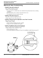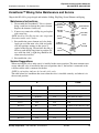
1
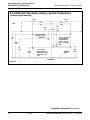
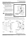
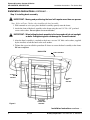
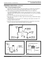
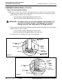
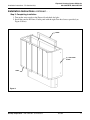
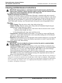
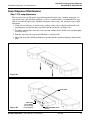
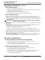
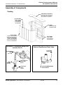
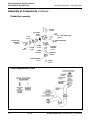
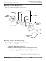
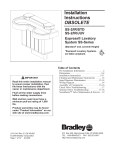
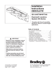
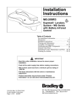
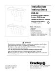
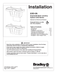
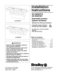
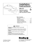
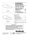
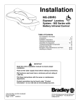
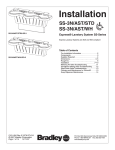
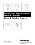
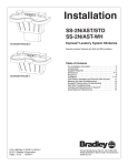
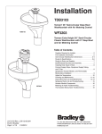
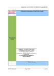
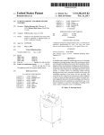
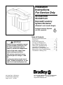
Installation
Instructions
For Service Only
SS-2/AST/STD
SS-2/AST/JUV
Express® Lavatory
System SS-Series
(Standard* and Juvenile Height)
Express® Lavatory Systems
are ADA compliant.
Table of Contents
IMPORTANT
Read this entire installation manual
to ensure proper installation, then
file these instructions with the
owner or maintenance department.
Flush all the water supply lines
before making connections.
Pre-Installation Information . . . . . . . . . . . . . . . .2
Dimensions . . . . . . . . . . . . . . . . . . . . . . . . . . .3-4
Installation Instructions . . . . . . . . . . . . . . . . 5-11
Cleaning and Maintenance . . . . . . . . . . . . . . . .12
Soap Dispenser Maintenance . . . . . . . . . . .13-14
Check Valve Troubleshooting . . . . . . . . . . . . . .14
Assembly of Components . . . . . . . . . . . . . .15-16
Metering Air Valve Maintenance . . . . . . . . . . .17
Metering Air Valve Troubleshooting . . . . . .17-18
Vernatherm™ Mixing Valve . . . . . . . . . . . . . . .19
Wall anchors used must have a
minimum pull-out rating of 1,000
lbs.
Product warranties may be found
under "Product Information" on our
web site at www.bradleycorp.com.
215-1244 Rev. C; EN 03-813
© 2004 Bradley Corporation
Page 1 of 19 5/11/04
P.O. Box 309, Menomonee Falls, WI 53052-0309
TEL. 1-800-BRADLEY FAX 262-251-5817
http://www.bradleycorp.com
Express® Lavatory System SS-Series
SS-2/AST/STD, SS-2/AST/JUV
Installation Instructions - For Service Only
Pre-Installation Information
Barrier-free and ADA compliant - standard height mounting
The SS-2/AST/STD Express® Lavatory System is compliant with Americans with Disabilities Act
(ADA). When mounted at 34" rim height, the Express® meets ADA, ANSI and UFAS requirements for barrier-free clearances, reaches and controls. Always check local codes and ordinances
for compliance.
Barrier-free and ADA compliant - juvenile height mounting
The SS-2/AST/JUV Express® Lavatory System is compliant with Americans with Disabilities Act
(ADA) Accessibility Guidelines for Buildings and Facilities: Building Elements Designed for
Children's Use; Final Rule.
Pushbutton and air valve
Each sprayhead is controlled by a pushbutton air valve, enabling each user to activate a single flow
of water. Air valves use 0.5 gpm for a ten-second duration, meeting the ANSI/ASHRAE/IES
90A-1980 Standard.
Supplies required for installation:
• (6) 3/8" wall anchors, bolts and washers to mount frame and bowl to wall
(minimum pull-out rating of 1,000 lbs.)
• 1/2" NPT hot and cold supply piping
• 1-1/2" NPT drain piping
2
5/11/04
Bradley Corporation • 215-1244 Rev. C; EN 03-813
Express® Lavatory System SS-Series
SS-2/AST/STD, SS-2/AST/JUV
Installation Instructions - For Service Only
SS-2/AST/STD Express® Lavatory System Dimensions
Standard Height Mounting
38-1/4"
(971)
8"
(203)
6"
(152)
22" (559)
34" (864)
50"
(1270)
8.5"
(216)
21"
(533)
10" (254)
Radius
8" (203)
Radius
30"
(762)
Dimensions continue . . .
Bradley Corporation • 215-1244 Rev. C; EN 03-813
5/11/04
3
Express® Lavatory System SS-Series
SS-2/AST/STD, SS-2/AST/JUV
Installation Instructions - For Service Only
Dimensions continued . . .
11"
(279)
38"
(965)
34"
(864)
Standard Height
SS-2/AST/STD
29"
(737)
9"
(229)
6"
(152)
4"
(102)
11"
(279)
34"
(864)
Juvenile Height
SS-2/AST/JUV
4
5/11/04
30"
(762)
25"
(635)
9"
(229)
6"
(152)
4"
(102)
Bradley Corporation • 215-1244 Rev. C; EN 03-813
Express® Lavatory System SS-Series
SS-2/AST/STD, SS-2/AST/JUV
Installation Instructions - For Service Only
Installation Instructions
Step 1: Rough in
Note: See Figure 1a below (for Standard Height) and Figure 1b on page 6 (for Juvenile Height)
when roughing in the Express®.
IMPORTANT: Flush the supply lines before making connections. Debris in supply
lines can cause the valves to malfunction.
IMPORTANT: Dimensions shown in Figure 1a are for Standard Height and in
Figure 1a for Juvenile Height.
1. Rough in 1/2" NPT hot and cold supply lines through wall at dimensions shown.
2. Rough in 1-1/2" NPT drain waste connection through wall at dimensions shown.
3. Install (6) 3/8" wall anchors with a minimum pull-out rating of 1,000 lbs. (supplied by
installer) at the locations shown in Figures 1a and 1b.
SS-2/AST/STD Express® Lavatory System Dimensions
Standard Height Mounting
23-1/2"
(597)
23-1/2"
(597)
9-3/8"
(238)
(MM)
1"
(25)
2-3/4"
(70)
3"
(76)
1-1/2" NPT DRAIN STUB OUT 2" (50)
FROM WALL
32"
(813)
1/2" NPT HOT AND
COLD SUPPLIES,
OR TEMPERED
SUPPLY - STUB
OUT 2" (50) FROM
WALL
28-5/8"
(727)
25"
(635)
11-3/8"
(289)
9-3/8"
(238)
(6) 3/8" WALL
ANCHORS WITH
MINIMUM PULLOUT
RATING OF 1,000
LBS.
Figure 1a
FINISHED
FLOOR
15-1/4"
(387)
CENTERLINE
Installation Instructions continue . . .
Bradley Corporation • 215-1244 Rev. C; EN 03-813
5/11/04
5
Express® Lavatory System SS-Series
SS-2/AST/STD, SS-2/AST/JUV
Installation Instructions - For Service Only
SS-2/AST/JUV Express® Lavatory System Dimensions
Juvenile Height Mounting
23-1/2"
(597)
23-1/2"
(597)
9-3/8"
(238)
(MM)
1"
(25)
2-3/4"
(70)
3"
(76)
1-1/2" NPT DRAIN STUB OUT 2" (50)
FROM WALL
28"
(711)
1/2” NPT HOT AND
COLD SUPPLIES
OR TEMPERED
SUPPLY - STUB
OUT 2” (50) FROM
WALL
24-5/8"
(625)
21"
(533)
11-3/8"
(289)
9-3/8"
(238)
(6) 3/8" WALL
ANCHORS WITH
MINIMUM PULLOUT
RATING OF 1,000
LBS.
FINISHED
FLOOR
15-1/4"
(387)
CENTERLINE
Figure 1b
Installation Instructions continue . . .
6
5/11/04
Bradley Corporation • 215-1244 Rev. C; EN 03-813
Express® Lavatory System SS-Series
SS-2/AST/STD, SS-2/AST/JUV
Installation Instructions - For Service Only
Installation Instructions continued . . .
Step 2: Mounting frame to wall
1. Remove the eight Torx-head screws
securing the panel to the frame, and
remove the panel (see Figure 3).
Note: Scuff panel does not need to be
removed.
2. Position the frame against the wall,
ensuring that it is level. If necessary,
insert shims under the frame until level.
Note: When mounted, the Standard and
Juvenile Height frames should rest on the
floor.
IMPORTANT: Anchoring the frame
to a wall that is not flat may
cause the frame to bend. If necessary, install shims to compensate for any wall distortion.
1-1/2" NPT DRAIN
STUB-OUT
1/2" NPT HOT AND
COLD SUPPLIES OR
TEMPERED SUPPLY
STUB-OUTS
Figure 2
3. Ensure that the back of the frame is flat against the wall. If wall is not flat, insert shims
behind the frame to ensure that it will not bend when anchored.
4. Once you have positioned the frame such that it is level and resting on the floor and flat
against the wall or shimmed, use the 3/8" bolts and washers to mount the frame to the wall
(see Figure 4).
FRAME
(4) 3/8" BOLT
AND WASHER
FRAME
PANEL
(8) TORX-HEAD
SCREW
SCUFF PANEL
(do not remove)
Figure 3
SCUFF PANEL
(do not remove)
Figure 4
Installation Instructions continue . . .
Bradley Corporation • 215-1244 Rev. C; EN 03-813
5/11/04
7
Express® Lavatory System SS-Series
SS-2/AST/STD, SS-2/AST/JUV
Installation Instructions - For Service Only
Installation Instructions continued . . .
Step 3: Installing bowl assembly
IMPORTANT: Moving and positioning the bowl will require more than one person.
Note: Refer to Figure 5 below when installing the bowl assembly.
1. With someone to assist you, place the bowl assembly squarely onto the frame.
2. Attach the front of the bowl assembly to the frame using the two 1/4"-20 x 3/8" pan-head
screws and washers. Do not tighten screws at this time.
IMPORTANT: When bolting the bowl assembly to the frame and wall, do not overtighten bolts. Overtightening bolts can damage the Terreon® material.
3. After the bowl assembly is attached to the frame, use two 3/8" bolts and washers (supplied
by the installer) to bolt the bowl to the wall anchors.
4. Tighten the screws installed in procedure #2 above to secure the bowl assembly to the frame.
Do not overtighten.
BACK VIEW
3/8" BOLT
AND
WASHER
BOWL ASSEMBLY
3/8" BOLT
AND
WASHER
1/4"-20 X 3/8"
PAN HEAD
SCREWS AND
WASHERS
Figure 5
Installation Instructions continue . . .
8
5/11/04
Bradley Corporation • 215-1244 Rev. C; EN 03-813
Express® Lavatory System SS-Series
SS-2/AST/STD, SS-2/AST/JUV
Installation Instructions - For Service Only
Installation Instructions continued . . .
Step 4: Connecting supply and drain
1. FOR HOT AND COLD SUPPLY: Connect the flexible hoses installed to the Vernatherm™
Mixing Valve to the hot and cold water supply piping from the wall (see Figure 6a).
Note: The red marking on Vernatherm™ Mixing Valve indicates hot water supply inlet.
FOR SINGLE TEMPERED SUPPLY: Attach the stop/strainer/check valve to the 1/2" tempered
supply line. Connect the flexible hose to the stop/strainer/check valve and air valve manifold
(see Figure 6b).
2. Install the drain plug in the hole in the bottom of the bowl (see Figure 7).
3. Beneath the bowl, install the 1/4" rubber washer onto the drain plug, and thread the tailpiece
to the drain plug.
4. Assemble the P-trap by connecting the 1-1/2" tubular pipe to the tailpiece and to the 1-1/2"
drain pipe stubbed out of the wall.
5. Install the strainer on the drain plug opening inside the bowl, and push the strainer firmly
into place. Secure the strainer to the drain with the screw provideed.
Figure 6a
FLEXIBLE
SUPPLY
HOSE
VERNATHERM™
THERMOSTATIC
MIXING VALVE
FLEXIBLE
SUPPLY
HOSE
CONNECT TO
1/2" NPT COLD
WATER SUPPLY
CONNECT TO
1/2" NPT HOT
WATER SUPPLY
FLEXIBLE
SUPPLY
HOSE
CONNECT TO
TEMPERED
WATER SUPPLY
Figure 6b
Bradley Corporation • 215-1244 Rev. C; EN 03-813
Figure 7
5/11/04
9
Express® Lavatory System SS-Series
SS-2/AST/STD, SS-2/AST/JUV
Installation Instructions - For Service Only
Installation Instructions continued . . .
Step 5: Connecting plastic tubing
NOTE: Refer to Figure 8a for hot and cold supplies, and refer to Figure 8b for tempered supply.
1. Connect the plastic tubing for the water supplies from the sprayhead assembly to the quickconnect fittings on the air valve as follows:
• insert the tubing with the red marking to the left valve
• insert the tubing with the green marking to the right valve
IMPORTANT: The plastic tubing for the water supplies and pushbuttons are
pre-cut to the correct lengths. If the tubing is cut too short,
kinking can occur and cause leaks at the fitting locations.
2. Connect the plastic tubing for the pushbuttons from the sprayhead assembly to the quick-connect
fittings on the air valve as follows:
• insert the tubing with the red marking to the left valve
• insert the tubing with the green marking to the right valve
3. Assemble the P-trap (supplied) and make drain connections.
AIR TUBING
(GREEN)
AIR TUBING
(RED)
WATER
SUPPLY
(GREEN)
WATER SUPPLY
(RED)
FLEXIBLE
SUPPLY HOSE
AIR VALVE
VERNATHERM™
MIXING VALVE
Figure 8a
AIR TUBING
(GREEN)
WATER
SUPPLY
(GREEN)
AIR TUBING
(RED)
WATER SUPPLY
(RED)
FLEXIBLE
SUPPLY HOSE
AIR VALVE
Figure 8b
10
5/11/04
Bradley Corporation • 215-1244 Rev. C; EN 03-813
Installation Instructions - For Service Only
Express® Lavatory System SS-Series
SS-2/AST/STD, SS-2/AST/JUV
Installation Instructions continued . . .
Step 5: Completing installation
1. Turn on the water supply to the Express® and check for leaks.
2. Install the panel to the frame. Fasten panel with the eight Torx-head screws provided (see
Figure 9 below).
FRAME
(8) TORX-HEAD
SCREW
PANEL
Figure 9
Bradley Corporation • 215-1244 Rev. C; EN 03-813
5/11/04
11
Express® Lavatory System SS-Series
SS-2/AST/STD, SS-2/AST/JUV
Installation Instructions - For Service Only
Cleaning and Maintenance Instructions
IMPORTANT: Strong alkaline or acid-based chemicals and cleansers should not be
used to clean Terreon®. If these chemicals come in contact with the Terreon® surface,
wipe off the surface immediately and flush with soapy water.
Terreon® and panel maintenance
The bowl and sprayhead cover are constructed of Terreon®, a densified solid surface material
composed of an acrylic modified polyester resin. Terreon® is resistant to chemicals, stains, burns
and impact. Surface damage can be easily repaired with everyday cleaners or fine grit abrasives.
The panel and sprayhead body are made of an acrylic/ABS laminate, and will not chip, peel or
flake. With regular cleaning, your Terreon® fixture will provide years of dependable service.
Cleaning
• Daily Cleaning: Wipe the surface with a damp cloth and wipe dry.
• Weekly Cleaning: Wipe the surface with a damp cloth and a household liquid detergent.
Stubborn stains can be removed as follows:
1. Using a #7448 Scotch-Brite® pad, scrub with an abrasive cleanser such as Ajax®,
Comet® or Soft Scrub® and water.
2. Clean thoroughly with soapy water and allow to dry.
• Scorch Marks: Although Terreon® will not burn, a lit cigarette in contact with Terreon®
could leave a scorch mark. Scorch marks can be removed by buffing with a #7448 ScotchBrite pad or with an abrasive cleaner.
• Repair kit: In the unlikely event your Terreon® surface becomes damaged, it can easily and
inexpensively be repaired. Contact your Bradley representative to order a repair kit and be
sure to specify color when ordering.
Panel cleaning
IMPORTANT: Do not use abrasive cleansers to clean the panel or sprayhead body.
Abrasive cleaners can mar the surface.
• Graffiti/Vandalism: If vandals create markings on the panel, Bradley recommends using
Motsenbocker’s LIFT OFF® to remove ink and spray paint. Remover #3 is for ink and markers,
and Remover #4 is for spray paint. Motsenbocker’s LIFT OFF® can be ordered through
Sanitary Maintenance Service Inc. (call 1-800-451-5523 x 425 or visit
www.santitarymaintenance.com/product.htm for ordering information). After cleaning with
LIFT OFF®, give the panel a final thorough cleaning with a liquid tub and tile cleaner to
remove soil and maintain the glossy finish.
NOTE: Use of brand names is intended only to indicate a type of cleaner. This does not constitute an
endorsement, nor does the omission of any brand name cleaner imply its inadequacy. Many products
named are regional in distribution and can be found in local supermarkets, department and hardware
stores or through your cleaning service. It is emphasized that all products should be used in strict
accordance with package instructions.
12
5/11/04
Bradley Corporation • 215-1244 Rev. C; EN 03-813
Installation Instructions - For Service Only
Express® Lavatory System SS-Series
SS-2/AST/STD, SS-2/AST/JUV
Soap Dispenser Maintenance
Step 1: Fill soap dispensers
The two soap valves will dispense vegetable/coconut oil liquid soaps, synthetic detergents, viscous lotion soaps, and antiseptic solutions. A 10-15% concentration is recommended for vegetable or coconut oil liquid soaps. Synthetic detergents, lotion soaps, and antiseptic soaps require
no dilution.
1. Using two screwdrivers (or similar tool), push up on the release tabs located beneath each
soap dispenser and pull out the soap tanks from the sprayhead (see Figure 10a).
2. To remove packing dust, rinse out each soap tank with hot water. Shake water out thoroughly
and allow to dry.
3. Pour the soap into each soap tank's filler hole (see Figure 10b).
4. After each soap tank is filled, position the soap tanks into the sprayhead openings and push into
place.
Figure 10a
FILLER HOLE
Figure 10b
SOAP TANK
133-107 (GRAY)
133-131 (PUTTY)
133-131A (COAL)
Bradley Corporation • 215-1244 Rev. C; EN 03-813
SOAP DISPENSER VALVE
S09-007
5/11/04
13
Express® Lavatory System SS-Series
SS-2/AST/STD, SS-2/AST/JUV
Installation Instructions - For Service Only
Soap Dispenser Maintenance continued . . .
Step 2: Change soap type
1. Pour out all of the soap from the dispenser.
2. Rinse the soap dispenser with hot water several times until all of the residue is removed, and
pump the valve until clean water appears.
3. Rinse the dispenser with ethyl alcohol and allow to air dry.
4. After the dispenser is dry, pour the new soap into the soap dispenser.
Step 3: Cleaning Instructions
Regular cleaning of the soap dispenser is recommended to ensure optimum performance and
maximum service life. Cleaning the soap dispenser monthly to remove soap residue, dirt, and
other accumulations should become a regular part of your washroom cleaning routine and general
maintenance program.
IMPORTANT: Do not use abrasive cleansers to clean the soap tank. Abrasive
cleaners can mar the surface.
Clean exterior: Use warm water and soap to clean the exterior of the soap dispenser. Dry with
a soft cloth.
Clean interior: Inspect the interior of the soap tank for residue or coagulation of soap. If
necessary, clean the soap tank according to the following procedure:
1. Pour out any remaining soap in the tank.
2. Fill the tank half-full of hot water and shake the tank to dislodge the soap residue.
3. Empty the water from the container and repeat steps 1 and 2 until the soap container is clean.
NOTE: If rinsing alone does not remove the soap residue, place a small chain (24 inches long)
into the soap tank with hot water and shake the container until the chain dislodges the residue.
Then remove the chain and rinse out the soap tank.
Clean internal components: To clean the internal components of the soap dispenser, pump
hot water through the soap dispenser until a clean flow of water comes out of the valve.
Check Valve Troubleshooting
If water just dribbles or does not flow from sprayhead:
1. Close the stops and check the valves that supply water to the lavatory system.
2 Inspect the stop/check valves for proper installation.
3. Remove the flexible hoses from the stop/check valves and clean the strainers, if necessary.
If water sprayhead delivers all hot or cold water:
1. Close the stops and check the valves that supply water to the lavatory system.
2. Inspect the stop/check valves for proper installation.
3. Remove the flexible hoses from the stop/check valves and clean the strainers, if necessary.
4. Inspect mixing valve for proper installation (see Vernatherm valve on page 19).
• A red marking indicates the hot inlet.
14
5/11/04
Bradley Corporation • 215-1244 Rev. C; EN 03-813
Installation Instructions - For Service Only
Express® Lavatory System SS-Series
SS-2/AST/STD, SS-2/AST/JUV
Assembly of Components
Paneling
SPRAYHEAD COVER/SHELF
(part number varies with color of
unit—contact your local Bradley
representative for assistance)
(10) TORX-HEAD
PANEL SCREW
160-378 (GRAY)
160-378A (PUTTY)
160-378B (COAL)
FRAME
Standard S17-238
Juvenile S17-239
ACCESS PANEL
Standard 186-1153 (GRAY)
Standard 186-1153A (PUTTY)
Standard 186-1153B (COAL)
Juvenile 186-1160 (GRAY)
Juvenile 186-1160A (PUTTY)
Juvenile 186-1160B (COAL)
SCUFF PANEL
185-030 (GRAY)
185-030A (PUTTY)
185-030B (COAL)
Vernatherm™ Thermostatic Mixing Valve
Assembly S67-571
Optional Stop/Strainer/Check Valve
90° ELBOW
169-639
VERNATHERM
VALVE
(S01-116B)
FILTER
WASHER
269-1188
FLEX HOSE WITH
SWIVEL END
269-653
STOP/CHECK
VALVE
S27-102
Bradley Corporation • 215-1244 Rev. C; EN 03-813
STOP/STRAINER/CHECK
VALVE S60-003
5/11/04
15
Express® Lavatory System SS-Series
SS-2/AST/STD, SS-2/AST/JUV
Installation Instructions - For Service Only
Assembly of Components continued . . .
Pushbutton assembly
SCREW
160-396
ACTUATOR
BODY
118-279
1/8” TUBE CONNECTOR
169-890
U-CUP
125-099
1/4” TUBE CONNECTOR
145-090
PUSHBUTTON
ASSEMBLY
S08-324
NUT
110-115
SPRING
135-065
PISTON
119-227
O-RING
125-001CK
STREAMFORMER
115-125
AERATOR
HOUSING
115-133
DIFFUSER
269-508
SCREW
160-289
Other Replacement Parts
16
5/11/04
Bradley Corporation • 215-1244 Rev. C; EN 03-813
Express® Lavatory System SS-Series
SS-2/AST/STD, SS-2/AST/JUV
Installation Instructions - For Service Only
Metering Air Valve Maintenance
Metering Air Valve Repair Kits and Parts List
VALVE SEAT
117-036
RUBBER DIAPHRAGM
269-665
PLASTIC DISK
269-664
LOWER
VALVE BODY
118-183
PARTS INCLUDED
IN KIT S65-110
STAINLESS
STEEL DISK
179-082
SPRING
135-053
REPAIR KIT
S73-054A
(Note: This repair
kit also includes
kit S65-110)
CENTER HOLE
LOCKWASHER
142-002CR
SCREW
160-313
Metering Air Valve Troubleshooting
Problem: Water is dripping from the streamformers
Cause: Debris on valve seat or orifices.
Solution: Clean and inspect the valve seat.
1. Remove screws and disassemble metering valve.
2. Clean the valve seat and inspect for deep gouges or scratches. Replace if necessary.
3. Remove all debris that may be clogging center hole of plastic diaphragm assembly.
4. Remove any debris clogging the off-center hole in the rubber diaphragm.
Metering Air Valve Troubleshooting continued . . .
Bradley Corporation • 215-1244 Rev. C; EN 03-813
5/11/04
17
Express® Lavatory System SS-Series
SS-2/AST/STD, SS-2/AST/JUV
Installation Instructions - For Service Only
Metering Air Valve Troubleshooting
Problem: Valve will not shut off.
Cause: Timing mechanism is clogged.
Solution: Clean timing mechanism:
1. If compressed air is available, blow water and debris from perforated metal sleeve of timing
mechanism.
2. Turn the adjusting screw in all the way but do not force screw.
3. Turn adjusting screw out to desired cycle time.
Problem: Valve will not turn on.
Cause: Water is not being supplied to the unit.
Solution: Open all stops on the mixing valve.
Problem: Timing can not be adjusted for more than 5 seconds.
Cause: There is an air leak.
Solution: Check assembly:
1. Check all tubing and fittings for proper assembly.
2. Tighten all screws which hold valve together.
Problem: Pushbutton does not work properly.
Cause: Air volume may not be sufficient to operate valve.
Solution: Check for leaks and lubricate U-cup:
1. Check all fittings for air leaks.
2. Disassemble pushbutton and lubricate U-cup seal (see pushbutton assembly diagram on page 15).
1/4" TUBE CONNECTOR
WITH FLOW CONTROL
METERING
AIR VALVE
18
5/11/04
Bradley Corporation • 215-1244 Rev. C; EN 03-813
Express® Lavatory System SS-Series
SS-2/AST/STD, SS-2/AST/JUV
Installation Instructions - For Service Only
Vernatherm™ Mixing Valve Maintenance and Service
*Repair kit S45-049 is pre-packaged and includes O-Ring, Flip Ring, Power Element and Spring.
Maintenance Instructions
1. Disassemble the Vernatherm™ Valve as shown,
being careful not to damage the power element.
Replace the element, if necessary.
2. If necessary, remove the old flip ring and replace
with a new ring.
NOTE: An old or worn flip ring may cause temperature
fluctuation and/or water chatter.
3. Reassemble the power element and valve body.
Apply grease to the main valve slide and gently
ease into position, rotating so that grease is
applied to the flip ring. Do not force the slide as
this may push the flip ring from its position. To
test, rotate the slide; a slight drag should be felt
when correctly installed.
4. Reassemble the valve.
Body
S73-027
Body (chrome)
S73-028
Power Element*
S27-019
Flip Ring*
125-015
Valve Slide
S01-039
Spring*
135-008
O-Ring*
125-001CH
Cover
107-261B
Screw
160-175
Service Suggestions
When servicing the valve, make sure it is installed in the correct position. The most common error
occurs when the valve is installed in the reversed position, that is, the hot line is connected to the
cold line and the cold is connected to the hot.
NOTE: A red marking indicates the hot side of the valve.
The table below lists conditions that occur when the valve is installed correctly, and when it is in
the reversed position.
IF
Valve Position is
THEN
Hot Supply
Cold Supply
Correct
Hot
Cold
Mixed 107°
Correct
Hot
No Water
Valve shuts off or drips
Correct
No Water
Cold
Valve shuts off or drips
Correct
Hot
Hot
Hot
Correct
Cold
Cold
Cold
Reversed
Hot
Cold
Cold/below 107° Hot/above 107°
Reversed
Hot
No Water
Hot
Reversed
No Water
Cold
Cold
Reversed
Hot
Hot
Hot
Reversed
Cold
Cold
Cold
Bradley Corporation • 215-1244 Rev. C; EN 03-813
Valve Delivers
5/11/04
19