1
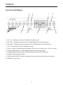
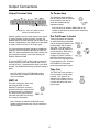
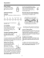
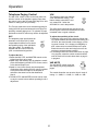
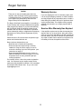
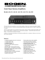
Gold Seal Series Amplifiers
Models GS-35, GS-60, GS-100, GS-150, GS-250
The Bogen Gold Seal Series amplifiers are an extraordinary addition to Bogen's line of quality audio amplifiers. Designed
with the sound contractor in mind, they provide unparalleled flexibility and versatility, without the need for expensive addon modules.
Unlike other typical amplifier lines, the professional sound contractor need not purchase a higher-powered amplifier just to
get more extensive features or flexibility. Each of the Gold Seal Series amplifiers — 250W, 150W, 100W, 60W and 35 W
models — incorporate the exact same set of features.
In addition to its extensive input flexibility, the Gold Seal Series amplifiers offer a combination of features not found in any
other commercial amplifier.
Features
•
•
•
•
•
•
•
•
•
•
•
•
•
4 dedicated microphone inputs (XLR connectors)
1 selectable Mic/Tel input
1 selectable Mic/Aux input
1 dedicated Aux input
4-ohm direct coupled output
8-ohm, 25V, 25VCT, and 70V transformercoupled outputs
35W, 60W, 100W, 150W and 250W versions
Rack mountable — 2RU package for all models
Dual function 10-band graphic equalizer (Acoustic
EQ/Feedback Control)
True loudness contour function
Aphex® Aural Exciter for improved intelligibility
Switchable phantom power supply
Variable Aux input muting
Downloaded from: http://www.guardianalarms.net
•
•
•
•
•
•
•
•
•
•
•
•
•
•
Remote master volume control capability
Input muting via contact on all inputs
Voice activated aux muting on Tel input
Automatic level control on Tel input
Aux fade back after Tel page
Preamp out/Power amp in connections
Booster amp output connection
Tape output connection
Balanced line driver output (using
WMT1A accessory)
Lo-cut filter for Mic channels
3-speed fan cooling (GS-250 only)
Available tamper resistant front cover
Available rack mounting kit
Available remote volume control
© 1997 Bogen Communications, Inc.
50 Spring St., Ramsey, NJ 07446
Publication No. 54-5941-04
9903
Printed in Korea
All rights are reserved. No part of this document may be
photocopied, reproduced, or translated to another language
without the prior written consent of Bogen Communications
Inc.
Notice: The information contained in this document is subject to change without notice and should not be construed
as a commitment by Bogen Communications, Inc.
Bogen Communications, Inc. assumes no responsibility
for any errors that may appear in this document nor
does it make an expressed or implied warranty of any
kind with regard to this material, including, but not limited to, the implied warranties of merchantability and
fitness for a particular purpose.
Bogen Communications Inc. shall not be liable for incidental
or consequential damages in connection with, or arising out
of the furnishing, performance, or use of this document and
the equipment which it describes.
Complete product warranty information is provided on a
separate product registration card.
WARNING
The Warning label calls attention to a procedure, practice,
or the like, which, if not correctly performed or adhered to,
could result in damage to the unit or personal injury. Do
not proceed beyond a warning label until the indicated conditions are fully understood and met.
Warning: Changes or modifications to this unit not
expressly approved by the party responsible for compliance
could void the user’s authority to operate the equipment.
Bogen® is a registered trademark of Bogen Communications, Inc.
APHEX® is a registered trademark of Aphex Inc.
Contents
Important Safety Information . . . . . . . . . . . . . . . . . . . . . . . . . . . . . . . . . . . . . . . . . . . . . . . . .2
Unpacking . . . . . . . . . . . . . . . . . . . . . . . . . . . . . . . . . . . . . . . . . . . . . . . . . . . . . . . . . . . . . . . .2
Packing List . . . . . . . . . . . . . . . . . . . . . . . . . . . . . . . . . . . . . . . . . . . . . . . . . . . . . . . . . . . .2
Accessories . . . . . . . . . . . . . . . . . . . . . . . . . . . . . . . . . . . . . . . . . . . . . . . . . . . . . . . . . . . .2
Features . . . . . . . . . . . . . . . . . . . . . . . . . . . . . . . . . . . . . . . . . . . . . . . . . . . . . . . . . . . . . . . . .3
Front panel (All Models) . . . . . . . . . . . . . . . . . . . . . . . . . . . . . . . . . . . . . . . . . . . . . . . . . . .3
Rear panel (Models GS-35, GS-60, GS-100, GS-150) . . . . . . . . . . . . . . . . . . . . . . . . . . . .4
Rear Panel (GS-250) . . . . . . . . . . . . . . . . . . . . . . . . . . . . . . . . . . . . . . . . . . . . . . . . . . . . .5
Input Connections . . . . . . . . . . . . . . . . . . . . . . . . . . . . . . . . . . . . . . . . . . . . . . . . . . . . . . . . .6
Mic 1-4 . . . . . . . . . . . . . . . . . . . . . . . . . . . . . . . . . . . . . . . . . . . . . . . . . . . . . . . . . . . . . . . .6
Mic 5/Tel . . . . . . . . . . . . . . . . . . . . . . . . . . . . . . . . . . . . . . . . . . . . . . . . . . . . . . . . . . . . . .6
Mic 6/Aux1 . . . . . . . . . . . . . . . . . . . . . . . . . . . . . . . . . . . . . . . . . . . . . . . . . . . . . . . . . . . . .6
Aux 2 . . . . . . . . . . . . . . . . . . . . . . . . . . . . . . . . . . . . . . . . . . . . . . . . . . . . . . . . . . . . . . . . .6
Phantom Power for Mic 5 & Mic 6 . . . . . . . . . . . . . . . . . . . . . . . . . . . . . . . . . . . . . . . . . . . .6
Remote Volume Control . . . . . . . . . . . . . . . . . . . . . . . . . . . . . . . . . . . . . . . . . . . . . . . . . . .7
Precedence Connections . . . . . . . . . . . . . . . . . . . . . . . . . . . . . . . . . . . . . . . . . . . . . . . . . .7
Output Connections . . . . . . . . . . . . . . . . . . . . . . . . . . . . . . . . . . . . . . . . . . . . . . . . . . . . . . . .8
Output Terminal Strip . . . . . . . . . . . . . . . . . . . . . . . . . . . . . . . . . . . . . . . . . . . . . . . . . . . . .8
WMT-1A . . . . . . . . . . . . . . . . . . . . . . . . . . . . . . . . . . . . . . . . . . . . . . . . . . . . . . . . . . . . . . .8
To Power Amp . . . . . . . . . . . . . . . . . . . . . . . . . . . . . . . . . . . . . . . . . . . . . . . . . . . . . . . . . .8
Pre-Out/Power In Jack . . . . . . . . . . . . . . . . . . . . . . . . . . . . . . . . . . . . . . . . . . . . . . . . . . . .8
Tape Out . . . . . . . . . . . . . . . . . . . . . . . . . . . . . . . . . . . . . . . . . . . . . . . . . . . . . . . . . . . . . .8
Operation . . . . . . . . . . . . . . . . . . . . . . . . . . . . . . . . . . . . . . . . . . . . . . . . . . . . . . . . . . . . . . . .9
Power Switch . . . . . . . . . . . . . . . . . . . . . . . . . . . . . . . . . . . . . . . . . . . . . . . . . . . . . . . . . . .9
Individual Volume Controls . . . . . . . . . . . . . . . . . . . . . . . . . . . . . . . . . . . . . . . . . . . . . . . . .9
Lo-Cut Filter . . . . . . . . . . . . . . . . . . . . . . . . . . . . . . . . . . . . . . . . . . . . . . . . . . . . . . . . . . . .9
Contour Pushbutton Switch . . . . . . . . . . . . . . . . . . . . . . . . . . . . . . . . . . . . . . . . . . . . . . . .9
Aphex Aural Exciter . . . . . . . . . . . . . . . . . . . . . . . . . . . . . . . . . . . . . . . . . . . . . . . . . . . . . .9
Dual Function Acoustic Equalizer . . . . . . . . . . . . . . . . . . . . . . . . . . . . . . . . . . . . . . . . . . . .9
Telephone Paging Control . . . . . . . . . . . . . . . . . . . . . . . . . . . . . . . . . . . . . . . . . . . . . . . . .10
Variable Mute . . . . . . . . . . . . . . . . . . . . . . . . . . . . . . . . . . . . . . . . . . . . . . . . . . . . . . . . . .10
Troubleshooting . . . . . . . . . . . . . . . . . . . . . . . . . . . . . . . . . . . . . . . . . . . . . . . . . . . . . . . . . .11
Maintenance . . . . . . . . . . . . . . . . . . . . . . . . . . . . . . . . . . . . . . . . . . . . . . . . . . . . . . . . . . . . .12
Bogen Service . . . . . . . . . . . . . . . . . . . . . . . . . . . . . . . . . . . . . . . . . . . . . . . . . . . . . . . . . . . .12
Technical Specifications . . . . . . . . . . . . . . . . . . . . . . . . . . . . . . . . . . . . . . . . . . . . . . . . . . . .13
1
Important Safety Instructions
1. Read and understand all instructions.
2. Follow all warnings and instructions marked on the product.
3. Unplug the product from the wall outlet before cleaning. Do not use liquid cleaners or aerosol cleaners. Use a damp
cloth for cleaning.
4. Do not use this product near water.
5. Do not place this product on an unstable cart, stand or table, where the product may fall, causing serious damage to the
product.
6. Slots and openings in the cabinet and the back or bottom are provided for ventilation, to protect it from overheating.
These openings must not be blocked or covered. This product should not be placed in a built-in installation unless proper ventilation is provided.
7. This product should be operated only from the type of power source indicated on the marking label.
8. The power supply included with this product has a 2-prong plug for connection with a standard electrical outlet. Do not
allow anything to rest on the power cord. Do not locate this product where the cord will be abused by persons walking
on it.
9. Do not overload wall outlets and extension cords as this can result in the risk of fire or electrical shock.
10.Never push objects of any kind into this product through cabinet slots as they may touch dangerous voltage points or
short out points that could result in a risk of fire or electric shock. Never spill liquid of any kind on the product.
11.To reduce the risk of electric shock, do not disassemble this product, but return it to the factory service center when
some service or repair work is required. Opening or removing covers may expose you to dangerous voltages or other
risks. Incorrect assembly can cause electric shock when the product is subsequently used.
12.Unplug this product from the wall and refer servicing to the factory service center personnel under the following conditions:
a.When the power supply cord or plug is damaged or frayed.
b. If liquid has been spilled into the product.
c. If the product has been exposed to rain or water.
d. If the product does not operate normally by following the operating instructions. Adjust only those controls that are
covered by the operating instructions because improper adjustment of other controls may result in damage.
e. If the product has been dropped or the cabinet has been damaged
f. If the product exhibits a distinct change in performance.
NOTE: SAVE THESE INSTRUCTIONS
Unpacking
Packing List
The unit was carefully checked before leaving the factory.
The Gold Seal Series carton contains the following components:
1 - Gold Seal Series unit
1 - User Manual
1 - Product Registration Card
Accessories
The following accessories are available for your Gold Seal Amplifier at additional cost:
• Model GSTRC — A plexiglass cover to protect control settings
• Model GSRPK — Rack mounting installation kit.
• Model GSRVC — A remote volume control to control volume of the amplifier from distances up to 1000 feet.
2
Features
Front Panel (All Models)
3
1
2
4
5
7
6
8
9
10
1. MIC 1 to 4 - Individual level controls for dedicated microphone inputs.
2. MIC 5/TEL - Individual level control for Mic or Tel input depending on input mode selected.
3. MIC 6/AUX 1 - Individual level control for Mic or Aux 1 input depending on input mode selected.
4. AUX 2 - Individual level control for dedicated Aux 2 input.
5. Contour - Enables or disables loudness equalization. Affects only Aux 2 and Mic 6/Aux 1 if set in aux mode.
6. Band Dual Mode Equalizer - 10 band graphic EQ with dual center frequency ability.
7. Dual Mode Equalizer Selector Switch - Selects EQ frequency bands or EQ defeat (OUT).
8. MASTER - Master output level control.
9. APHEX AURAL EXCITER - Enables or disables the Aphex Aural Exciter effect. Affects all input signals.
10. POWER - AC Power switch.
3
Features
Rear Panel (GS-35, GS-60, GS-100 & GS-150)
1
5
7
22
14
16
18
19
20
12
3
4
10 9
11 6 8 21
2
17
13
15
1. Amplifier Output - Terminal strip containing all the Gold Seal output taps.
2. VOX - Variable control for adjusting TEL input signal level trigger point for automatic muting of Aux input
(works only in the TEL input mode).
3. REMOTE MSTR - Screw terminal pair for connection of remote master volume control (Bogen model:
GSRVC).
4. MIC/AUX/TEL PRECEDENCE - Screw terminal connections that allow externally controlled muting of individual inputs.
5. WMT-1A - RCA connection for Bogen model WMT-1A 600 ohm balanced line matching transformer.
6. TAPE OUT - RCA unbalanced output, pre EQ and master volume.
(Mics are post Lo-Cut filter, see #14 below).
7. TO PWR AMP - RCA connection provides a high impedance, unbalanced signal level output as a feed to
high impedance inputs of other external amplifiers.
8. AX - Variable control for adjusting the amount of Aphex Aural Exciter effect.
9. PRE OUT - RCA unbalanced output from preamp/mixer stage for connection to external signal processing
equipment (used in conjunction with POWER IN and LINK switch).
10. POWER IN - RCA unbalanced direct input to power amp stage for connection to external signal processing
equipment (used in conjunction with PRE OUT and LINK switch).
11. LINK - Switch that makes or breaks the internal connection between preamp/mixer stage and power amp
stage for use with external signal processing equipment.
12. AUX 2 - RCA unbalanced input for dedicated Aux 2 input.
13. MIC 1 to 4 - Balanced XLR connectors for dedicated microphone inputs.
14. LO CUT FILTER - Enables or disables low frequency roll off (65 Hz) for all microphone inputs.
15. PHANTOM (MIC 1 to 4) - Individual switches enables or disables phantom power to each of the 4 dedicated
microphone inputs (MIC 5 and MIC 6 phantom power selection — see page 6).
4
Features
Rear Panel (GS-250)
14
1
22
8
21 2
16
18
19
20
12
6
3
4
5
7
23
10
9
11
17
13
15
16. MIC 6/AUX 1 - Switch selects either MIC 6 or AUX 1 connections as input.
17. AUX 1 - RCA unbalanced input for Aux 1 input signal (works only when AUX 1/MIC 6 switch is set to AUX
1).
18. MIC 6 - Screw terminals for balanced microphone (active only when AUX 1/MIC 6 switch is set to MIC 6).
19. MIC 5/TEL - Dual function Screw terminals for either balanced microphone or 600 ohm balanced input from
telephone page port.
20. MIC 5/TEL - Switch selects mode of operation for MIC 5/TEL input.
21. ALC - Variable control to adjust the amount of automatic level control applied to the TEL input (works only in
the TEL input mode).
22. VAR MUTE - 4 Switch selectable levels of Aux input signal muting during TEL page (works only in the TEL
input mode).
23. Fan - 3 speed fan for efficient cooling (GS-250 only).
5
Input Connections
source to the AUX 1 RCA jack (only works when the
AUX 1/MIC 6 switch is in the AUX1 position).
Installation Note
Keep input leads away from the output leads and
AC power cables. Unless the driving source provides a low-impedance output, keep the input lead
under ten feet in length. Make all connections to
the unit with the POWER switch in the OFF position.
AUX 2
The AUX 2 input uses an RCA plug
and accepts input from a dedicated
AUX source.
MIC 1- 4
2
1
3
2
Phantom Power for MIC 5 & MIC 6
1
3
2
1
3
2
1
A single internal jumper is provided to supply phantom
power to both MIC 5 and MIC 6. The amplifier is
shipped with the jumper in the OFF position. See the
figure below for the location of the phantom power
jumper.
1 — GND
2—+
3—-
3
MIC 5 and MIC 6 input terminal strip
MIC 1 through 4 utilize female XLR-type microphone
connectors. A slide switch located above each XLR
connector is used to supply phantom power for condenser microphones.
MIC 5/TEL
Front
The MIC 5/TEL input is designed to accept input from
a microphone or from a telephone line. A slide switch
is provided to select MIC 5 or TEL input. To connect a
microphone, place the MIC 5/TEL switch in the MIC
position. Use two conductor shielded cable and connect the cable shield to the center GND terminal. To
use the TEL input, place the MIC 5/TEL switch in the
TEL position and connect the 600 ohm telephone paging source (dry signal only - no DC voltage) to the MIC
5/TEL screw terminals.
Phantom Power Jumper Location For
Mic 5 and Mic 6
Warning
Removal of the amplifier cover exposes internal
components and presents an electrical shock hazard. For this reason, do not perform any functions
requiring removal of the cover of the amplifier
unless you are qualified to do so. Always disconnect AC power from the unit before attempting to
remove the cover.
MIC 6/AUX 1
The MIC 6/AUX 1 input is designed to accept input
from a microphone using terminal strip connections or
from a high level auxiliary source such as a tuner or
CD player using the AUX 1 RCA jack. A slide switch is
used to select input type. Connect a microphone to the
screw terminals labeled MIC 6 (works only when AUX
1/MIC 6 switch is in the MIC 6 position). Use two conductor shielded cable and connect the cable shield to
the center GND terminal. Connect an auxiliary input
6
Input Connections
Remote Volume Control
Precedence Connections
If remote volume control is desired, connect the Bogen
accessory GS-RVC remote volume control to the
screw terminals marked REMOTE MSTR. Wire length
can be up to 1000 feet using 22 gauge wire.
Precedence connections allow any combination of
inputs to be completely muted with a contact closure.
Closing a contact across any of the precedence terminals and the PREC COM 1 terminal will mute that
input. A customer-supplied normally-open SPST
switch, push-to-talk switch, microphone switch, relay
or telephone system contact can be used to provide
the closure.
Note: Activating the precedence control for Aux
inputs completely mutes the input signal. The
VAR MUTE control has no effect when muting
inputs using precedence control.
7
Output Connections
Output Terminal Strip
To Power Amp
The Gold Seal Series amplifier
may be used to drive an external
power amplifier (can only be
used with unbalanced high
impedance inputs).
4Ω Output LINK shorting clip
Note: Shorting clip between GND/COM on the
speaker output terminals strip must be installed to
use this feature.
Shorting Clip - Leave for unbalanced lines.
Remove for balanced lines
Speaker systems are connected directly to the speaker output terminals on the rear panel. Connect one
speaker lead to the COM terminal and the other to the
terminal corresponding to the impedance of the speaker system. Select only one of the output types.
Pre Out/Power In Jacks
These jacks permit the insertion
of signal processing equipment
into the signal path between the
preamp output and the power
amp input. The LINK switch
should be in the IN position for
normal operation. When using
external signal processing
equipment, place the switch in
the OUT position and connect
PRE OUT to the signal processing equipment’s input. Connect
the POWER IN to the signal
processing equipment’s output.
For ground-referenced output operation (unbalanced
systems), leave the shorting clip between COM and
GND. For special applications that require floating outputs (balanced systems), remove the shorting clip
between COM and GND.
To use the DIRECT OUT (4-ohm) output, remove the
shorting clip across the LINK terminals and connect
one lead to the 4Ω terminal and the other to the GND
terminal. The GND/COM shorting clip should remain in
place.
Tape Out
The TAPE OUT jack provides a
line level output to feed a tape
recorder. The output is not
effected by the Master volume
control or EQ, however, the Locut filter does affect the microphone inputs.
Note:The WMT-1A and TO PWR AMP outputs
cannot be used if speaker GND/COM shorting
clip is not installed.
WMT-1A
This RCA output jack, when used
with a Bogen WMT-1A Line
Matching Transformer accessory
provides a 600 ohm output to feed
a remote amplifier or a telephone
line. Refer to the instructions provided with the WMT-1A accessory
for connection information.
Note: Shorting clip between GND/COM on the
speaker output terminals strip must be installed to
use this feature.
8
Operation
Power Switch
The rear panel AX adjustment controls
the mix of the Aphex effect with the audio
signal. Counterclockwise rotation of the
control minimizes the Aphex effect.
Clockwise rotation of the control maximizes the Aphex effect.
The POWER switch applies
power to the unit. The switch
will illuminate when power is
on.
Dual Function Acoustic Equalizer
Individual Volume
Controls
The unique dual-function equalizer can be used for
acoustic shaping or for feedback control.
Each input is controlled by an individual volume control.
The overall volume is controlled by the
MASTER control.
Lo-Cut Filter
Note: When the switch is placed in the OUT position, the equalizer is bypassed for a flat response.
The Lo-Cut filter on the rear panel
provides 3dB attenuation @ 65Hz
on the microphone inputs. This
helps reduce mic breath pop, wind
noise and rumble.
Acoustic Shaping Mode
When the switch is set in the ACOUSTIC EQ position,
full range equalization (10 bands on 1 octave centers
starting at 62.5Hz) is provided with a boost/cut of
12dB. In this mode, the equalizer can be used to compensate for room acoustics, or to satisfy the listening
preference of the user.
Contour Pushbutton Switch
This switch enables or bypasses
the variable loudness contour.
This feature only effects the Aux
inputs.
Feedback Control Mode
This feature is designed to improve richness of sound
by restoring the high and low frequencies that the ear
is insensitive to at low volume levels. The effect diminishes as volume is increased.
When the switch is placed in the FEEDBACK CONTROL position, the equalizer can be used to reduce
feedback and increase the effective gain of the system.
Aphex Aural Exciter
In feedback control mode the equalizer provides
increased control of frequencies between 125Hz and
8KHz. The 10 bands are located on 2/3 octave centers with 12dB cut/boost on each band.
The front panel APHEX AURAL
EXCITER pushbutton enables or
bypasses the Aphex Aural
Exciter feature. This feature
effects all inputs when enabled.
This audio enhancement system recreates the presence and realism that is lost in the audio amplification
process, by regenerating the harmonics usually lost
through amplification. This results in increased presence and clarity, increased intelligibility, greater perceived loudness (without adding extra power), and
reduced listener fatigue.
9
Operation
Telephone Paging Control
VOX
The MIC 5/Tel volume control on the front panel controls the volume of the telephone paging input when
the control is set to the Tel mode (See page 6 for information on setting the Tel input mode).
The telephone page input features
voice activated Aux muting. This
feature always mutes AUX 2 and
only mutes AUX 1 when the
AUX1/MIC 6 is set in that position.
The Tel input mode uses voice activated triggering for
muting the AUX inputs and automatic level control for
providing constant paging level. To optimize Tel input
performance the ALC control may need to be adjusted.
The VOX control should be set so that only the
desired signal is above the threshold level, while
unwanted noise or signal is below it.
ALC
The telephone page input features an
automatic level control (ALC) which
compensates for different voice levels
and speaking styles of the individuals
using the system. The amplifier is
shipped with this control in the OFF
(max. counterclockwise) position.
To adjust the ALC:
1.Rotate the MIC 5/TEL and MASTER controls to the
highest level likely to be used.
2.Speak softly and distinctly into the telephone mouthpiece while adjusting the MIC 5/TEL volume control
to the desired output level.
3.Speak in a loud voice directly into the telephone
mouthpiece while rotating the ALC control clockwise
to the point where the output of the amplifier is
reduced to the same level as that obtained in
Step 2.
4.The MIC 5/TEL and MASTER controls can be used
to vary the overall volume without upsetting the ALC
adjustment.
To adjust the sensitivity of the circuit:
1. Rotate the VOX control fully clockwise. While making a public address announcement and talking at a
low level, the sound should not be choppy or missing parts of words. If it is choppy or intelligibility is
poor, rotate control counterclockwise to the point
where the sound is clear and crisp (but not to the
maximum counterclockwise position).
2. If the background music shuts down when no page
is in progress, rotate the control counterclockwise
until the music will not shut down when no page is
in progress.
VAR MUTE
The VAR MUTE control mutes the
Aux input(s) only during telephone
pages.
The control allows the user to select from 4 levels of
muting: 1 = -60dB, 2 = -21dB, 3 = -10dB, 4 = 0dB.
10
Troubleshooting
Amplifier will not turn ON.
On the GS-35, GS-60, GS-100 and GS-150, depress the
circuit breaker.
On the GS-250, check the fuse. Replace fuse only with
same type and rating.
No output on 70V, 25CT, or 25V.
Check that the LINK switch on the rear panel is in the IN
position or external signal-processing equipment, if used,
is functioning
Make sure that the shorting clip on the DIRECT OUT 4Ω
output is in place.
No telephone output.
Make sure that the MIC 5/TEL switch is in the TEL position.
When connecting the telephone Tip & Ring, make sure to
use the two outside terminals and not the center terminal
(GND).
Aux input will not mute with
telephone page.
Check that the VAR MUTE control is not set to 4 (0dB).
This control adjusts the level of the background music
when making a page. See page 10.
Microphone squeals or hums when
using the 3-pin connectors but not
when using screw terminals.
Check your wiring connections for the 3-pin connector.
Pin 1 is the shield connection. Pins 2 and 3 connect
to high and low leads on the mic cable.
Condenser Mic will not work.
Make sure that phantom power switch (MIC 1 - 4) is on.
See page 6.
Mic 5 and 6 use circuit board jumper. See page 6.
Telephone input cuts off the music,
without making a page.
Adjust the VOX control on the rear panel to eliminate any
unwanted noise that may be triggering the auto-mute circuit
See page 10.
Telephone input is choppy or
cuts off the beginning of a page.
Adjust the VOX control counterclockwise to make the
trigger activate at a lower input signal level. See page 10.
The telephone page volume is too
loud on some pages.
Adjust the ALC control on the rear panel. See page 10.
AUX 1 input not working
Make sure MIC 6/AUX 1 switch is in the AUX 1 position.
Make sure the signal source is plugged into the AUX 1
RCA jack.
11
Bogen Service
Caution
There are no user-serviceable parts within the
amplifier. Have all internal servicing performed by
a qualified technician. The warranty may become
void if repairs are performed by other than the
Bogen Factory Service Department.
The Bogen Gold Seal Series Amplifier is covered by a
3-year warranty and overnight installation-site replacement program (see below). If you encounter difficulty
with your Bogen Gold Seal amplifier, please do not
hesitate to ask our advice or assistance. Information
can be obtained by calling our Application Engineering
Department or Factory Service Department at (201)
934-8500.
Please be sure to fill out and return the product registration card included with this unit.
Warranty Service
If you are shipping the unit for a warranty repair, pack
it in the original shipping container or similar container
and ship prepaid via any responsible carrier. Include a
letter stating the problem and proof of purchase showing the purchase date. The amplifier will be promptly
repaired and returned to you freight prepaid while in
warranty.
Service After Warranty Has Expired
If the amplifier requires service after the warranty has
expired, ship it to us as per above, along with a letter
giving us your name and address. We will examine the
unit and contact you with an estimate of repairs before
any repair is made. Return shipment of equipment not
in warranty will be at the expense of the owner.
Best results are obtained when you:
• Read the User’s Guide before operating
• Ensure all input and output wiring is correctly
installed. If using the 4-ohm output, be sure to
remove the shorting clip in the LINK position (see
instructions on page 7).
• Ensure that the LINK switch (see the section on
PRE OUT/POWER IN JACKS on page 7) is in the
IN position when not using external signal processing equipment.
For warranty service, refer to the product registration
card. Our customer service support center can be
reached at (201) 934-8500, extension 1310, weekdays
from 9AM to 8PM, Eastern time. Or you can e-mail
[email protected].
12
Technical Specifications
Power Rating (RMS):
GS-35 —
GS-60 —
GS-100 —
GS-150 —
GS-250 —
Frequency Response:
Transformer Output —
Direct —
Distortion:
Direct —
Transformer —
Signal-to-Noise Ratio:
Fundamental —
Aux 1 & 2 —
Tel —
Mic 1 - 6 —
Inputs/Outputs:
Mic —
Aux—
Telephone —
Output to Power Amp —
Power In/Pre Out —
WMT-1A Output —
Tape Output —
Output Impedance:
Output Regulation:
Variable Mute Range:
ALC:
VOX Threshold:
Mic Precedence:
Loudness Contour:
Aphex Aural Exciter:
Overload Protection:
Thermal Protection:
Line Fusing:
Dimensions:
Shipping Weight:
GS-35 —
GS-60 —
GS-100 —
GS-150 —
GS-250 —
35 watts
60 watts
100 watts
150 watts
250 watts
65Hz to 20KHz +0/-2dB @ -2dB
20Hz to 20KHz, +0/-1dB @ rated power
0.5% (max.), 0.3% (typ.), 20Hz to 20KHz
0.5% (max.), 0.3% (typ.), 65Hz to 20KHz @ -2dB
-94dB or better;
-70dB
-70dB or better @ 600 ohms
-60dB or better @ 200 ohms
6 Lo-Z balanced via 4 XLR connectors and 2 screw terminals.
Sensitivity: 0.35mV (200Ω)
2 Hi-Z RCA jacks. Sensitivity: 0.085V (10Kohms)
Screw terminals. Sensitivity: 0.07V (600Ω)
5V @ Rated Output via RCA jack
In 1V/Out 1V via RCA jacks
25V @ Rated Output via RCA jack
687mV @ Rated Output via RCA jack
Balanced or unbalanced 8-ohms, 25V, 25VCT, 70V; 4-ohm direct unbal.
Better than 2dB from no load to full load
4 steps, -60, -21, -10, 0dB (Aux 1 & 2)
Distortion - less than 0.5%; Compression - 25dB
Input 20mV (VOX control max. CW position)
-60dB (via terminal strip Mic 1, 2, 3, 5/Tel, 6/Aux, Aux 2
+8dB @ 100Hz, +4dB @ 10KHz (Aux 1 & 2 control at 1/4 CW position)
Type A9
Electronic with automatic reset
105°C (220°F) thermistor attached to heat sink
Resettable circuit breaker (GS35/60/100/150),
Slo-Blo Fuse 6A/125VAC (GS250)
16.5”W x 3.5”H x 12”D All Models
19
24
28
31
33
lbs
lbs
lbs
lbs
lbs.
Bogen® is a registered trademark of Bogen Communications, Inc.
APHEX® is a registered trademark of Aphex Inc.
13
50 Spring Street, Ramsey, NJ 07446
Tel. 201-934-8500 Fax: 201-934-9832
www.bogen.com