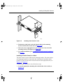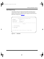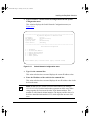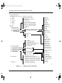
1
89301010.BK Page i Tuesday, June 10, 1997 8:00 PM
Using the
BayStack 303 and 304
Ethernet Switches
Part No. 893-01010-A
June 1997
89301010.BK Page ii Tuesday, June 10, 1997 8:00 PM
4401 Great America Parkway
Santa Clara, CA 95054
8 Federal Street
Billerica, MA 01821
© 1997 by Bay Networks, Inc. All rights reserved.
Trademarks
Bay Networks is a registered trademark of Bay Networks, Inc. BayStack and Bay Networks Press are trademarks of
Bay Networks, Inc.
Other brand and product names are registered trademarks or trademarks of their respective holders.
Statement of Conditions
In the interest of improving internal design, operational function, and/or reliability, Bay Networks, Inc. reserves the
right to make changes to the products described in this document without notice.
Bay Networks, Inc. does not assume any liability that may occur due to the use or application of the product(s) or
circuit layout(s) described herein.
Portions of the code in this software product are Copyright © 1988, Regents of the University of California. All rights
reserved. Redistribution and use in source and binary forms of such portions are permitted, provided that the above
copyright notice and this paragraph are duplicated in all such forms and that any documentation, advertising materials,
and other materials related to such distribution and use acknowledge that such portions of the software were
developed by the University of California, Berkeley. The name of the University may not be used to endorse or
promote products derived from such portions of the software without specific prior written permission.
SUCH PORTIONS OF THE SOFTWARE ARE PROVIDED “AS IS” AND WITHOUT ANY EXPRESS OR
IMPLIED WARRANTIES, INCLUDING, WITHOUT LIMITATION, THE IMPLIED WARRANTIES OF
MERCHANTABILITY AND FITNESS FOR A PARTICULAR PURPOSE.
In addition, the program and information contained herein are licensed only pursuant to a license agreement that
contains restrictions on use and disclosure (that may incorporate by reference certain limitations and notices imposed
by third parties).
RESTRICTED RIGHTS LEGEND: Use, duplication, or disclosure by the U.S. Government is subject to the
restrictions set forth in subparagraph (c)(1) of the Commercial Computer Software—Restricted Rights clause of
FAR52.227-19 or subparagraph (c)(1)(a) of the Rights in Technical Data and Computer Software clause of DFARS
52.227-7013, and any successor rules or regulations, whichever is applicable.
Federal Communications Commission (FCC) Statement
Note: This equipment has been tested and found to comply with the limits for a Class A digital device, pursuant to Part
15 of the FCC rules. These limits are designed to provide reasonable protection against harmful interference when the
equipment is operated in a commercial environment. This equipment generates, uses, and can radiate radio frequency
energy. If it is not installed and used in accordance with the instruction manual, it may cause harmful interference to
radio communications. Operation of this equipment in a residential area is likely to cause harmful interference, in
which case users will be required to take whatever measures may be necessary to correct the interference at their own
expense.
ii
893-01010-A
89301010.BK Page iii Tuesday, June 10, 1997 8:00 PM
EN 55 022 Declaration of Conformance
This is to certify that the Bay Networks BayStack 303 and 304 Ethernet Switches are shielded against the generation
of radio interference in accordance with the application of Council Directive 89/336/EEC, Article 4a. Conformity is
declared by the application of EN 55 022 Class A (CISPR 22).
Caution: This device is a Class A product. In a domestic environment, this device can cause radio
interference, in which case, the user may be required to take appropriate measures.
893-01010-A
iii
89301010.BK Page iv Tuesday, June 10, 1997 8:00 PM
iv
893-01010-A
89301010.BK Page v Tuesday, June 10, 1997 8:00 PM
Contents
Preface
Purpose ...........................................................................................................................xiii
Audience ..........................................................................................................................xiii
Conventions .....................................................................................................................xiv
Special Message Formats .........................................................................................xiv
Two-tiered Procedure Format ....................................................................................xiv
Use of Enter, Type, and Press ...................................................................................xiv
Ordering Bay Networks Publications ............................................................................... xv
Bay Networks Customer Support .................................................................................... xv
How to Get Help .............................................................................................................. xv
For More Information .......................................................................................................xvi
Safety Messages
Safety Alert Message Format .........................................................................................xvii
Safety Alert Messages Used in This Guide .....................................................................xix
Chapter 1
Introduction to the BayStack 303 and 304
Ethernet Switches
Features .........................................................................................................................1-1
Physical Description .......................................................................................................1-3
Front Panel ...............................................................................................................1-3
10BASE-T Ports ................................................................................................1-4
10/100BASE-TX Port .........................................................................................1-5
MDA Slot ............................................................................................................1-6
Console Port Connector ....................................................................................1-6
LEDs ..................................................................................................................1-7
Power Cord Specifications ..............................................................................................1-8
893-01010-A
v
89301010.BK Page vi Tuesday, June 10, 1997 8:00 PM
Chapter 2
Installing the BayStack Switches
Installation Requirements ...............................................................................................2-1
Installation Procedure .....................................................................................................2-2
Installing the BayStack Switches on a Flat Surface .................................................2-2
Installing the BayStack Switch in a Rack .................................................................2-4
Installing a Metal Chassis in a Rack ..................................................................2-5
Installing a Plastic Chassis in a Rack ................................................................2-6
Completing Rack Mounting Installation .............................................................2-8
Attaching Devices to the BayStack Switch ...............................................................2-9
Connecting 10BASE-T Ports .............................................................................2-9
Connecting the 10/100BASE-TX Port .............................................................2-10
Connecting the 100BASE-FX Port ..................................................................2-11
Connecting to the Console Port .......................................................................2-12
Power-up Self-Tests ...............................................................................................2-13
Initial Setup of a BayStack Ethernet Switch .................................................................2-15
Using Factory Default Settings ...............................................................................2-15
Selecting a Language ............................................................................................2-16
Initial Switch Setup .................................................................................................2-17
Chapter 3
Customizing and Managing the BayStack Switches
Using the Menus and Screens .......................................................................................3-1
Menu and Screen Areas ..........................................................................................3-3
Switch Status Area ............................................................................................3-4
Central Screen Area ..........................................................................................3-4
Navigation Commands and Command Line Area .............................................3-4
Menu and Screen Descriptions ......................................................................................3-5
Language Selection Menu ..............................................................................................3-6
Main Menu ......................................................................................................................3-6
System Information ..................................................................................................3-7
Switch Information .............................................................................................3-7
Spanning Tree Information .................................................................................3-7
Port Statistics and Status Information .............................................................3-10
System Configuration .............................................................................................3-12
Switch Network Configuration .........................................................................3-13
vi
893-01010-A
89301010.BK Page vii Tuesday, June 10, 1997 8:00 PM
Port Configuration ............................................................................................3-14
Spanning Tree Configuration ...........................................................................3-14
SNMP Configuration ........................................................................................3-16
Reset to Default ...............................................................................................3-17
Reset System .........................................................................................................3-17
Exit Telnet ...............................................................................................................3-17
Using the BayStack Switch ...........................................................................................3-17
Configuration Examples .........................................................................................3-17
Spanning Tree Protocol ..........................................................................................3-19
Managing the BayStack Switches ..........................................................................3-20
Network Management with SNMP ...................................................................3-20
Network Management through a Serial I/O Connection ..................................3-22
Network Management Using a Telnet Connection ...........................................3-22
Upgrading Switch Software Through TFTP Connection ...............................................3-23
Chapter 4
Troubleshooting and Diagnostics
BayStack 303 and 304 Switch-related Issues ................................................................4-1
Autonegotiation ........................................................................................................4-2
MDI and MDI-X Connections ...................................................................................4-3
Installation-related Issues ...............................................................................................4-4
Addresses ................................................................................................................4-5
Cabling .....................................................................................................................4-5
Link Status ...............................................................................................................4-6
Appendix A
Technical Specifications
General Specifications ................................................................................................... A-1
Declaration of Conformity .............................................................................................. A-3
Appendix B
Media Dependent Adapters (MDAs)
100BASE-FX MDA ....................................................................................................... B-1
10/100BASE-TX MDA .................................................................................................. B-3
Installing an MDA .......................................................................................................... B-4
Index
893-01010-A
vii
89301010.BK Page viii Tuesday, June 10, 1997 8:00 PM
viii
893-01010-A
89301010.BK Page ix Tuesday, June 10, 1997 8:00 PM
Figures
Figure 1-1.
Figure 1-2.
BayStack 304 switch front panel ..............................................................1-3
BayStack 303 switch front panel ..............................................................1-4
Figure 2-1.
Figure 2-2.
Figure 2-3.
Figure 2-4.
Figure 2-5.
Figure 2-6.
Figure 2-7.
Figure 2-8.
Figure 2-9.
Figure 2-10.
Figure 2-11.
Positioning the chassis in the rack ...........................................................2-4
Installing metal chassis in rack ................................................................2-5
Installing the plastic chassis in the rack ...................................................2-7
10/100 Mb/s port connections ................................................................2-10
SC connection for the 100BASE-FX MDA port ......................................2-11
Connecting to the console port ..............................................................2-13
Power Up Self Test screen .....................................................................2-14
Language selection menu ......................................................................2-16
Main Menu .............................................................................................2-17
System Configuration menu ...................................................................2-18
Switch Network Configuration menu ......................................................2-19
Figure 3-1.
Figure 3-2.
Figure 3-3.
Figure 3-4.
Figure 3-5.
Figure 3-6.
Figure 3-7.
Menu and screen hierarchy .....................................................................3-2
Menu and screen areas ...........................................................................3-3
BayStack 304 switch as a segment switch .............................................3-18
BayStack 303 as a desktop switch .........................................................3-19
Power Up Self Test screen .....................................................................3-23
Boot Options Menu ................................................................................3-24
Switch Software Upgrade Menu ............................................................3-25
Figure 4-1.
Figure 4-2.
MDI-X to MDI cable connections .............................................................4-3
MDI-X to MDI-X cable connections ..........................................................4-4
Figure B-1.
Figure B-2.
Figure B-3.
100BASE-FX MDA ................................................................................. B-2
10/100BASE-TX MDA ............................................................................ B-3
Installing an MDA ................................................................................... B-5
893-01010-A
ix
89301010.BK Page x Tuesday, June 10, 1997 8:00 PM
x
893-01010-A
89301010.BK Page xi Tuesday, June 10, 1997 8:00 PM
Tables
Table 1-1.
Table 1-2.
Table 1-3.
Table 1-4.
Table 1-5.
RJ-45 connector pinout ............................................................................1-5
DB-9 connector pin assignments .............................................................1-7
Front-panel LEDs .....................................................................................1-7
Power and Status LEDs ...........................................................................1-8
International power cord specifications ....................................................1-9
Table 2-1.
Factory default settings ..........................................................................2-15
Table B-1.
Table B-2.
100BASE-FX MDA LEDs ....................................................................... B-2
100BASE-TX MDA LEDs ....................................................................... B-4
893-01010-A
xi
89301010.BK Page xii Tuesday, June 10, 1997 8:00 PM
xii
893-01010-A
89301010.BK Page xiii Tuesday, June 10, 1997 8:00 PM
Preface
Congratulations on your purchase of the Bay Networks® BayStack 303 Ethernet
Switch or the BayStack 304 Ethernet Switch. The BayStack™ Ethernet switches
are intended for small segment workgroups and power-user desktops and provide
both 10BASE-T ports and 100BASE-T ports.
Purpose
This guide presents information about using the features and capabilities of the
BayStack 303 and 304 Ethernet Switches, installing a switch, and configuring the
switch through the user interface.
Audience
This guide is intended for Ethernet administrators with the following background:
893-01010-A
•
Working knowledge of basic Ethernet and network management concepts and
terminology
•
Familiarity with 10BASE-T and 100BASE-T specifications
•
Working knowledge of tools and procedures for installing and operating
sensitive electronic equipment
xiii
89301010.BK Page xiv Tuesday, June 10, 1997 8:00 PM
Using the BayStack 303 and 304 Ethernet Switches
Conventions
This section describes the conventions used in this guide.
Special Message Formats
This guide uses the following formats to highlight special messages:
Note: This format is used to highlight information of importance or special
interest.
Caution: This format is used to highlight information that will help you prevent
equipment failure or loss of data.
Two-tiered Procedure Format
The procedural steps in this guide are presented in a two-tiered format. The first
tier describes the step very briefly but precisely. An experienced user may need to
read only the first tier to complete the task. The second tier describes the step in
more detail and includes results of performing the step.
Use of Enter, Type, and Press
This guide uses “enter,” “type,” and “press” to describe the following actions:
xiv
•
When you read “enter,” type the text and press the Enter key.
•
When you read “type,” type the text, but do not press the Enter key.
•
When you read “press,” press only the alphanumeric or named key.
893-01010-A
89301010.BK Page xv Tuesday, June 10, 1997 8:00 PM
Preface
Ordering Bay Networks Publications
To purchase additional copies of this document or other Bay Networks
publications, order by part number from Bay Networks Press™ at the following
numbers:
•
Phone—U.S./Canada: 1-888-422-9773
•
Phone—International: 1-510-490-4752
•
Fax—U.S./Canada and International: 1-510-498-2609
Bay Networks Customer Support
You can purchase a support contract from your Bay Networks distributor or
authorized reseller, or directly from Bay Networks Services. For information
about, or to purchase a Bay Networks service contract, either call your local Bay
Networks field sales office or one of the following numbers:
Region
Telephone number
Fax number
United States and
Canada
1-800-2LANWAN; then enter Express
Routing Code (ERC) 290, when prompted,
to purchase or renew a service contract
1-508-670-8766
1-508-916-8880 (direct)
Europe
33-4-92-96-69-66
33-4-92-96-69-96
Asia/Pacific
61-2-9927-8888
61-2-9927-8899
Latin America
561-988-7661
561-988-7550
How to Get Help
If you purchased a service contract for your Bay Networks product from a
distributor or authorized reseller, contact the technical support staff for that
distributor or reseller for assistance.
893-01010-A
xv
89301010.BK Page xvi Tuesday, June 10, 1997 8:00 PM
Using the BayStack 303 and 304 Ethernet Switches
If you purchased a Bay Networks service program, call one of the following Bay
Networks Technical Solutions Centers:
Technical Solutions Center Telephone number
Fax number
Billerica, MA
1-800-2LANWAN
508-670-8765
Santa Clara, CA
1-800-2LANWAN
408-495-1188
Valbonne, France
33-4-92-96-69-68
33-4-92-96-69-98
Sydney, Australia
61-2-9927-8800
61-2-9927-8811
Tokyo, Japan
81-3-5402-0180
81-3-5402-0173
For More Information
For information about Bay Networks and its products, visit the Bay Networks
World Wide Web (WWW) site at http://www.baynetworks.com. To learn more
about Bay Networks Customer Service, select Customer Service on the opening
Web page.
xvi
893-01010-A
89301010.BK Page xvii Tuesday, June 10, 1997 8:00 PM
Safety Messages
Übersetzter Sicherheitshinweis
Traduction des Messages de Sécurité
Traducción de los mensajes de seguridad
Messaggi relativi alla sicurezza
This section translates the safety alert messages used in this guide. Safety alert
messages notify users of unsafe actions or conditions that could lead to personal
injury or equipment damage.
Safety Alert Message Format
All safety alert messages are tagged with an international alert symbol. When you
see a safety alert in this guide, be sure to read, understand, and follow the
instructions provided before continuing with the procedure.
The safety alert messages in this guide appear in the following format:
Symbol
Meaning (English, German, French, Spanish, Italian, Japanese)
Warning: A warning alerts the user to some action or set of conditions that
could result in personal injury.
Caution: A caution alerts the user to some action or set of conditions that
could result in damage to the equipment.
893-01010-A
xvii
89301010.BK Page xviii Tuesday, June 10, 1997 8:00 PM
Using the BayStack 303 and 304 Ethernet Switches
Symbol
Meaning (English, German, French, Spanish, Italian, Japanese)
Vorsicht: Dieser Sicherheitshinweis macht den Benutzer auf Maßnahmen
oder Bedingungen aufmerksam, die die Verletzung von Personen zur Folge
haben können.
Achtung: Dieser Sicherheitshinweis macht den Benutzer auf Maßnahmen
oder Bedingungen aufmerksam, die eine Beschädigung der Geräte zur Folge
haben können.
Avertissement : La mention Avertissement attire l'attention de l'utilisateur
sur une action ou un ensemble de conditions pouvant causer des blessures
corporelles.
Attention : La mention Attention attire l'attention de l'utilisateur sur une
action ou un ensemble de conditions pouvant endommager l'équipement visé.
Advertencia: Un mensaje de advertencia avisa al usuario sobre una acción o
conjunto de condiciones que pueden causar daños personales.
Precaución: Un mensaje de precaución avisa al usuario sobre alguna acción
o conjunto de condiciones que pueden dañar el equipo.
Avvertenza: L'avvertenza indica all'utente la presenza di una o più
condizioni che possono causare lesioni fisiche.
Attenzione: Questo messaggio indica all'utente la presenza di una o più
condizioni che possono causare danni alle apparecchiature.
xviii
893-01010-A
89301010.BK Page xix Tuesday, June 10, 1997 8:00 PM
Safety Messages
Safety Alert Messages Used in This Guide
The following safety alert message are used throughout this guide. Please read
and follow these instructions when you encounter them in the text.
Class A Product
Copyright page
Caution: This device is a Class A product. In a domestic environment, this
device can cause radio interference, in which case, the user may be required to
take appropriate measures.
Achtung: Dieses Gerät ist ein Produkt der Klasse A. Bei Heiminstallationen
kann dieses Gerät Störungen des Rundfunkempfangs verursachen, wodurch
der Benutzer gegebenenfalls entsprechende Maßnahmen ergreifen muß.
Attention : Appareil électrique de classe A pouvant causer des
radio-interférences en utilisation domestique et nécessiter, le cas échéant,
l'application de mesures correctives appropriées.
Precaución: Este dispositivo es un producto de la Clase A. En un entorno
doméstico, este dispositivo puede producir interferencias de radio, en cuyo
caso, puede exigirse al usuario que tome las medidas de corrección apropiadas.
Attenzione: Questo dispositivo è un prodotto di Classe A. Se utilizzato in
ambiente domestico, può causare interferenze radio e, in tal caso, l'utente
dovrà prendere le opportune precauzioni.
893-01010-A
xix
89301010.BK Page xx Tuesday, June 10, 1997 8:00 PM
Using the BayStack 303 and 304 Ethernet Switches
Accumulated Weight (Shelf or Table Mount)
See Caution on page 2-2.
Caution: When this device is installed in a stack on a shelf or tabletop, the
accumulated weight of the port cables increases with the height of the shelf or
tabletop.
Achtung: Wenn dieses Gerät in einem Stapel auf einem Tisch oder einem
Regalboden installiert wird, erhöht sich das Gesamtgewicht der
Schnittstellenkabel mit der Höhe des Regalbodens oder Tisches.
Attention : Si l'appareil est posé dans un rack ou sur une étagère, notez bien
que le poids du câblage réseau augmente avec la hauteur de l'installation.
Precaución: Cuando este dispositivo se instala apilado en un estante o sobre
una mesa, el peso acumulado de los cables de los puertos aumenta según la
altura del estante o de la mesa.
Attenzione: Quando il dispositivo viene installato in stack su un ripiano o su
un tavolo, il peso dei cavi connessi alle porte aumenta in proporzione
all'altezza del ripiano o del tavolo.
xx
893-01010-A
89301010.BK Page xxi Tuesday, June 10, 1997 8:00 PM
Safety Messages
Stacking Units in a Rack
See Caution on page 2-3.
Caution: When mounting this device in a rack, do not stack units directly on
top of one another in the rack. Each unit must be secured to the rack with
appropriate mounting brackets. Mounting brackets are not designed to support
multiple units.
Achtung: Wenn Sie dieses Gerät in einem Gerätegestell installieren, stellen
Sie die Geräte nicht direkt aufeinander. Jedes Gerät muß mit entsprechenden
Halterungen im Gestell befestigt werden. Die Halterungen sind nicht dafür
konzipiert, mehrere Geräte zu tragen.
Attention : Si cet appareil doit être encastré dans un rack, ne jamais empiler
directement plusieurs unités les unes sur les autres. Chaque unité doit être
correctement fixée avec les membrures appropriées. Les membrures ne sont
pas conçues pour supporter le poids d'unités multiples.
Precaución: Al montar este dispositivo apilado con otros dispositivos, no
apile las unidades directamente unas sobre otras. Cada unidad se debe fijar a la
estructura mediante los soportes de montaje adecuados. Los soportes de
montaje no están diseñados para soportar varias unidades.
Attenzione: Se il dispositivo viene installato su una cremagliera, non
impilarlo su un altro dispositivo montato sulla cremagliera. Ciascuna unità
deve essere fissata alla cremagliera con le apposite staffe di montaggio. Tali
staffe non possono essere utilizzate per fissare più unità.
893-01010-A
xxi
89301010.BK Page xxii Tuesday, June 10, 1997 8:00 PM
Using the BayStack 303 and 304 Ethernet Switches
Turning Off Power to the Unit
See Warning on page 2-3.
Warning: Removal of the power cord is the only way to turn off power to this
device. The power cord must always be connected in a location that can be
accessed quickly and safely in case of an emergency.
Vorsicht: Die Stromzufuhr zu diesem Gerät kann nur durch Ziehen des
Netzstromkabels unterbrochen werden. Die Netzsteckdose, an die das
Netzstromkabel angeschlossen ist, muß sich stets an einem Ort befinden, der
bei einem Notfall schnell und einfach zugänglich ist.
Avertissement : Le débranchement du cordon d'alimentation constitue le
seul moyen de mettre cet appareil hors tension. Le cordon d'alimentation doit
donc toujours être branché dans une prise accessible pour faciliter la mise hors
tension en cas d'urgence.
Advertencia: La única forma de desconectar la alimentación de este
dispositivo es desenchufar el cable de alimentación. El cable de alimentación
siempre debe estar conectado en una ubicación que permita acceder al cable de
forma rápida y segura en caso de emergencia.
Avvertenza: Estrarre il cavo di alimentazione è l'unico sistema per spegnere
il dispositivo. Il cavo di alimentazione deve essere sempre collegato in una
posizione che permetta l'accesso facile e sicuro in caso di emergenza.
xxii
893-01010-A
89301010.BK Page xxiii Tuesday, June 10, 1997 8:00 PM
Safety Messages
Reset To Default Settings Command
See Caution on page 3-17.
Caution: If you choose the Reset to default settings command, all of your
configured settings will be replaced with factory default settings when you
press [Enter].
Achtung: Bei Auswahl des Befehls zur Rücksetzung auf die
Standardeinstellungen werden alle von Ihnen konfigurierten Einstellungen
durch die werkseitigen Standardeinstellungen ersetzt, wenn Sie die
Eingabetaste drücken.
Attention : Si vous restaurez la configuration usine, votre configuration
courante sera remplacée par la configuration usine dès que vous appuierez sur
[Entrée].
Precaución: Si selecciona el comando Restaurar valores predeterminados,
todos los valores de configuración se sustituirán por las valores
predeterminados en fábrica al pulsar [Intro].
Attenzione: Nel caso in cui si selezioni la reimpostazione dei valori di
default, tutte le impostazioni configurate verranno sostituite dai default di
fabbrica premendo il tasto [Invio].
893-01010-A
xxiii
89301010.BK Page xxiv Tuesday, June 10, 1997 8:00 PM
Using the BayStack 303 and 304 Ethernet Switches
Removing the Top Cover
See Warning on page 4-1.
Warning: To avoid bodily injury from hazardous electrical current, never
remove the top cover of the device. There are no user-serviceable components
inside.
Vorsicht: Um Verletzungsgefahr durch einen elektrischen Stromschlag
auszuschließen, nehmen Sie niemals die obere Abdeckung vom Gerät ab. Im
Geräteinnern befinden sich keine Komponenten, die vom Benutzer gewartet
werden können.
Avertissement : Pour éviter tout risque d'électrocution, ne jamais retirer le
capot de l'appareil. Cet appareil ne contient aucune pièce accessible par
l'utilisateur.
Advertencia: A fin de evitar daños personales por corrientes eléctricas
peligrosas, no desmonte nunca la cubierta superior de este dispositivo. Los
componentes internos no son reparables por el usuario.
Avvertenza: Per evitare lesioni fisiche dovute a scariche pericolose di
corrente, non rimuovere mai il coperchio superiore del dispositivo. I
componenti interni non possono essere manipolati dall'utente.
xxiv
893-01010-A
89301010.BK Page 1 Tuesday, June 10, 1997 8:00 PM
Chapter 1
Introduction to the BayStack 303 and 304
Ethernet Switches
This chapter introduces the BayStack 303 and 304 Ethernet Switches and covers
the following topics:
•
Summary of key features
•
Physical description
Features
The BayStack 303 and 304 Ethernet Switches are members of the Bay Networks
BayStack family of high-performance Ethernet solutions. Both BayStack 303 and
304 switches have built-in management software and power-up diagnostics that
allow the switch to begin Ethernet frame switching functions immediately. These
BayStack switches provide switch connectivity between 802.3 Ethernet device
running any network protocols.
The BayStack 303 and 304 switches have 10 Mb/s ports, autonegotiating
10/100 Mb/s ports, and a 100 Mb/s media adapter (MDA) slot for either a
10/100BASE-TX or a 100BASE-FX fiber port connection.
The 10BASE-T port density of the BayStack 303 switch is ideal for low-cost
performance-enhancing segmentation within the wiring closet, and the higher port
density of the BayStack 304 switch allows the extension of dedicated switching to
power desktop users. The 100 Mb/s ports provide a high-throughput connection to
a backbone or server and can be configured to operate in either half- or full-duplex
data transfer mode. The 100BASE-T ports can also be used to provide a link
between traditional 10BASE-T networks and the faster 100BASE-T networks.
893-01010-A
1-1
89301010.BK Page 2 Tuesday, June 10, 1997 8:00 PM
Using the BayStack 303 and 304 Ethernet Switches
Multiple switches can be connected to one another (or to other 802.1D bridges/
switches/hubs) to form a switched/segmented (or bridged) Ethernet backbone.
Key features of the BayStack 303 and 304 Ethernet Switches are:
•
Provides 10 Mb/s and 100 Mb/s switching in the following configurations:
— 12 (BayStack 304) or 24 (BayStack 303) 10BASE-T half-duplex ports
with standard RJ-45 connections
— One 10/100BASE-TX half- or full-duplex autonegotiating port
— Addition of an optional 10/100BASE-TX half- or full-duplex
autonegotiating copper port or 100BASE-FX fiber port
•
Supports IEEE 802.3u autonegotiation standard on 10/100BASE-TX ports
•
Supports up to 1024 media access control (MAC) addresses per switch
•
Provides store-and-forward switching mode
•
Provides significant aggregate throughput for all packet sizes, including the
minimum size (64 bytes) Ethernet frame:
— 420,000 packets per second (pps) for BayStack 304 Ethernet Switch
— 380,000 pps for the BayStack 303 Ethernet switch
1-2
•
Supports IEEE 802.1d Spanning Tree Protocol on each port to provide
automatic network configuration of a loop-free topology and redundant
inter-switch links
•
Supports broadcast and multicast traffic control
•
Provides user interface that supports international languages: English,
German, French, Italian, Spanish, Japanese, and Chinese
•
Supports in-band Telnet connections through any port
•
Provides SNMP (Simple Network Management Protocol) manageability
through any port; supports MIB II and Bridge MIB
•
Supports Groups 1, 2, 3, and 9 RMON
•
Supports TFTP remote software image download
•
Provides indicators for power, system, and port operation
893-01010-A
89301010.BK Page 3 Tuesday, June 10, 1997 8:00 PM
Introduction to the BayStack 303 and 304 Ethernet Switches
Physical Description
This section provides descriptions of the components on the front panels of the
BayStack 303 and 304 Ethernet Switches.
Front Panel
The front panels of these BayStack switches provide RJ-45 10BASE-T ports, an
RJ-45 10/100BASE-T port, an expansion slot for the addition of either a 10/
100BASE-TX or 100BASE-FX port, a DB-9 connector for a console, and
assorted LEDs. Figure 1-1 shows the BayStack 304 Ethernet Switch, and
Figure 1-2 shows the BayStack 303 Ethernet switch. Descriptions of the ports and
LEDs follow the figures.
1
2
3
304
1
MDA
3
5
7
9
11
Power
100BASE-TX
Link
100BASE-TX
Console
1
3
5
7
9
11
2
4
6
8
10
12
100
F Dx
13
2
4
6
8
10
12
5
4
899EB
1 = One 10/100BASE-TX port
2 = 12 10BASE-T ports
3 = Console port connection∆
4 = Expansion slot for the addition of an optional 10/100BASE-TX or 100BASE-FX MDA
(switch should be powered down to install MDA)
5 = Status indicators
Figure 1-1.
893-01010-A
BayStack 304 switch front panel
1-3
89301010.BK Page 4 Tuesday, June 10, 1997 8:00 PM
Using the BayStack 303 and 304 Ethernet Switches
.
1
2
3
303
1
MDA
3
5
7
9
11
13
15
17
19
21
23
Power
Status
100BASE-TX
Link
100BASE-TX
Console
1
3
5
7
9
11
13
15
17
19
21
23
2
4
6
8
10
12
14
16
18
20
22
24
100
F Dx
25
2
4
6
8
10
12
14
16
18
20
22
24
5
4
896EB
1 = One 10/100BASE-TX port
2 = 24 10BASE-T ports
3 = Console port connection
4 = Expansion slot for the addition of an optional 10/100BASE-TX or 100BASE-FX MDA
(switch should be powered down to install MDA)
5 = LED status indicators
Figure 1-2.
BayStack 303 switch front panel
10BASE-T Ports
The 10BASE-T port connections are provided for the 10 Mb/s Ethernet segment
or nodes to attach to the BayStack 303 and 304 Ethernet Switches. The RJ-45
jacks accept standard Category 3, 4, or 5 copper unshielded twisted pair (UTP)
cable connections. Pin assignments for the standard RJ-45 connector are given in
Table 1-1. The BayStack switches are shipped with the 10BASE-T connectors
configured as MDI-X (media-dependent interface-crossover). These ports connect
over straight cables to the network interface controller (NIC) card in a node or
server, similar to a conventional Ethernet repeater hub. If you are connecting to
another Ethernet hub or Ethernet switch, you need a crossover cable unless an
MDI connection exists on the associated port of the attaching device (see
“Connecting 10BASE-T Ports” on page 2-8 for a description of the crossover
cable).
The 10 Mb/s ports operate in half-duplex mode only, and each port has an
associated LED that indicates link status of the line.
1-4
893-01010-A
89301010.BK Page 5 Tuesday, June 10, 1997 8:00 PM
Introduction to the BayStack 303 and 304 Ethernet Switches
Table 1-1.
RJ-45 connector pinout
Pin
1
8
3165.1
MDI-X signal
1
Receive data + (RD+)
2
Receive data –(RD–)
3
Transmit data + (TR+)
4
Not used
5
Not used
6
Transmit data– (TD–)
7
Not used
8
Not used
10/100BASE-TX Port
Both the BayStack switches have one built-in and one optional 10/100BASE-TX
port that is designed to operate either at 10 Mb/s or at 100 Mb/s depending on the
connecting device. This port supports the IEEE 802.3u autonegotiation standard,
which means that when this port is connected to another device that also supports
the IEEE 802.3u autonegotiation standard, the two devices negotiate the best
speed and duplex mode of operation.
The 10/100BASE-TX port also supports half- and full-duplex mode operation.
For more information on autonegotiation, see “Connecting the 10/100BASE-TX
Port” on page 2-9.
The 10/100 Mb/s port consists of a standard 8-pin modular RJ-45 connector used
to connect hubs, switches, and end stations using only 2-pair Category 5 UTP
cabling.
The link status indicator for the 100BASE-TX port is located on the LED panel on
the front of the switch. This area also contains a full-duplex (F Dx) status
indicator that lights when the port is operating in full-duplex mode. When the port
is operating in half-duplex mode, the indicator is off. See “Half-duplex and
Full-duplex Mode” on page 2-9 for more information on duplex mode.
893-01010-A
1-5
89301010.BK Page 6 Tuesday, June 10, 1997 8:00 PM
Using the BayStack 303 and 304 Ethernet Switches
A speed LED (100) is also provided to indicate when the port is operating as a
100 Mb/s port. The LED is off when the port is operating as a 10 Mb/s port. See
“Autonegotiation” on page 2-10 for more information on autonegotiation of wire
speed.
Like the 10BASE-T ports, all 10/100BASE-T ports are also configured as MDI-X.
Table 1-1 on page 1-5 lists the pin assignments for the RJ-45 connector.
MDA Slot
Each BayStack switch is configured with one expansion slot that can be populated
with an optional plug-in media-dependent adapter (MDA) to support a high-speed
connection to servers, shared Fast Ethernet hubs, or backbone devices. Two types
of media adapters are available for the BayStack switches:
•
Model MTX-1, 10/100BASE-TX copper connection
•
Model MFX-1, 100BASE-FX fiber connection
Both media types support half- and full-duplex operation and have an LED to
indicate when the port is operating in full-duplex mode. See Appendix A,
“Technical Specifications,” for a full description of the MDA.
Warning: Power to the switch must be turned off prior to installation of the
MDA.
Console Port Connector
The console port has a DB-9 male connector used to connect a management
terminal to the BayStack switch by means of a straight-through DB-9 to DB-9
standard serial port cable. Using a terminal, you can monitor the results of startup
self-diagnostics, perform manual boot configuration and SNMP agent
configuration, and customize your network using the supplied menus and screens.
The console port runs at 9600 baud and uses 8 data bits, 1 stop bit, and no parity
as the communications format, with flow control disabled.
In less complex applications with no network management, where no
configuration changes are required, you do not need to use the console port on the
BayStack switches.
1-6
893-01010-A
89301010.BK Page 7 Tuesday, June 10, 1997 8:00 PM
Introduction to the BayStack 303 and 304 Ethernet Switches
The console port connector pin assignments are described in Table 1-2.
Table 1-2.
DB-9 connector pin assignments
Pins
DB-9
1
5
6
9
3166.3
Signal name
Direction
1
Not used
2
Transmit data, TD
To terminal
3
Receive data, RD
From terminal
4
Not used
5
Common signal ground
6
Not used
7
Not used
8
Not used
9
Not used
For information about connecting a terminal to the console port, refer to
Chapter 2, “Installing the BayStack Switches.”
LEDs
The LEDs on the front panel of the BayStack switches help you to identify the
unit port status and MDA operational mode (see Table 1-3). LEDs associated with
the RJ-45 port connectors allow you to identify the link status of each port.
Table 1-3.
Front-panel LEDs
Type
Label
Color
State
Meaning
Link status of
each port
Link
Green
On
Link is active and connected correctly.
Off
Link is inoperative or improperly connected.
On
Switch is receiving valid AC power.
Off
Switch is not receiving valid AC power, or internal power
supply has failed.
On
Unit is operating properly.
Blinking
Unit is performing self-tests or network configuration.
Off
A system fault has occurred.
Unit AC
power supply
status
Power
System
status
Status
893-01010-A
Green
Green
1-7
89301010.BK Page 8 Tuesday, June 10, 1997 8:00 PM
Using the BayStack 303 and 304 Ethernet Switches
Table 1-3.
Front-panel LEDs (continued)
Type
Label
Color
State
Meaning
100 Mb/s speed
indicator *
100
Green
On
Port is operating at 100 Mb/s.
Off
Port is operating at 10 Mb/s.
On
10/100 Mb/s port is operating in full-duplex mode
(simultaneous transmit and receive).
Off
10/100 Mb/s port is operating in half-duplex mode
(transmit or receive).
Half/full-duplex *
F Dx
Green
* Indicator applies to 10/100BASE-TX port only (port 13 on BayStack 304 and port 25 on BayStack 303).
The unit AC power supply status LED and the system status LED work together
to provide status information. Table 1-4 provides the meaning of the two LEDs.
Table 1-4.
Power and Status LEDs
Power
Status
Meaning
Off
Off
System off.
On
Off
System fault detected by power-up diagnostics.
On
Blinking
System is powered on and performing self-tests or network
configuration.
On
On
Normal operation.
Power Cord Specifications
For installation outside North America, make sure you have the proper power cord
for your region. Any cord used must have a CEE-22 standard V female connector
on one end and must meet the IEC 320-030 specifications.
Caution: Use only power cords with a grounding path. Without a proper
ground, a person touching the unit is in danger of receiving an electrical shock.
Lack of a grounding path to the unit may result in excessive conducted or
radiated emissions.
1-8
893-01010-A
89301010.BK Page 9 Tuesday, June 10, 1997 8:00 PM
Introduction to the BayStack 303 and 304 Ethernet Switches
Table 1-5 lists specifications for international power cords.
Table 1-5.
International power cord specifications
Country/Plug description
Specifications
Continental Europe:
• CEE7 standard VII male plug
• Harmonized cord (HAR marking
on the outside of the cord jacket
to comply with the CENELEC
Harmonized Document HD-21)
220 or 230 VAC
50 Hz
Single phase
U.S./Canada/Japan:
• NEMA5-15P male plug
• UL recognized (UL stamped
on cord jacket)
• CSA certified (CSA label
secured to the cord)
100 or 120 VAC
50–60 Hz
Single phase
United Kingdom:
• BS1363 male plug with fuse
• Harmonized cord
240 VAC
50 Hz
Single phase
Typical plug
228FA
227FA
229FA
Australia:
• AS3112-1981 Male plug
240 VAC
50 Hz
Single phase
230FA
893-01010-A
1-9
89301010.BK Page 10 Tuesday, June 10, 1997 8:00 PM
89301010.BK Page 1 Tuesday, June 10, 1997 8:00 PM
Chapter 2
Installing the BayStack Switches
This chapter provides the following information for the BayStack switches:
•
Installation requirements
•
Installation procedure
•
Instructions for attaching devices
•
Instructions for the initial switch setup
Refer to Chapter 3, “Customizing and Managing the BayStack Switches,” to
further configure your BayStack switches.
Installation Requirements
Before installing a The BayStack 303 or 304 switch, verify that the package
contains the following items in addition to this guide:
•
A BayStack 303 Ethernet Switch or BayStack 304 Ethernet Switch
•
Power cable (applicable for operating country; see “Power Cord
Specifications” on page 1-8).
•
Rack-mounting kit (applicable for metal chassis or plastic chassis)
•
Warranty card
You will need a Phillips screwdriver for the installation.
Install the BayStack switches on a sturdy, level surface in a ventilated area that is
dust free and away from heat vents, warm air exhaust from other equipment, and
direct sunlight. Avoid proximity to large electric motors or other electromagnetic
equipment. When choosing a location, observe the guidelines listed in
Appendix A, “Technical Specifications.”
893-01010-A
2-1
89301010.BK Page 2 Tuesday, June 10, 1997 8:00 PM
Using the BayStack 303 and 304 Ethernet Switches
If you install the BayStack switches in a rack, ground the rack to the same
grounding electrode used by the power service in the area. The ground path must
be permanent and must not exceed 1 ohm of resistance from the rack to the
grounding electrode.
Installation Procedure
This section provides the requirements and instructions for installing the
BayStack switches on a flat surface or in a standard 19-inch utility rack. Both
switches can be shipped with either a metal chassis or a plastic chassis. The
installation instruction differs slightly depending on the type of chassis you
receive. Therefore, prior to installing your switch, determine which type of chassis
you have.
Installing the BayStack Switches on a Flat Surface
The BayStack switches can be mounted onto any appropriate flat surface that can
safely support the weight of a switch and its attached cables, as long as there is
adequate space around the unit for ventilation and access to cable connectors.
Caution: When this device is installed in a stack on a shelf or tabletop, the
accumulated weight of the port cables increases with the height of the shelf or
tabletop.
To install the switch on a tabletop, shelf, or any other flat surface, follow these
steps:
1.
Set the switch on the flat surface and check for proper ventilation.
Allow at least 2 inches on each side for proper ventilation and 5 inches at the
back for power cord clearance.
2.
Attach rubber feet to each marked location on the bottom of the metal
chassis.
The plastic chassis does not require rubber feet.
3.
Attach all devices to the ports.
See “Attaching Devices to the BayStack Switch” on page 2-8 through
page 2-11.
2-2
893-01010-A
89301010.BK Page 3 Tuesday, June 10, 1997 8:00 PM
Installing the BayStack Switches
4.
You can stack switches on top of one another to configure a switched/
bridged/segmented Ethernet backbone.
For performance reasons, the high-speed ports should be used to interconnect
switches.
5.
Attach the power cord to the back of the switch.
The BayStack switches do not have a power on/off switch. When you connect
the AC power cord to a suitable AC outlet, the switch powers up immediately.
Warning: Removal of the power cord is the only way to turn off power to
this device. The power cord must always be connected in a location that
can be accessed quickly and safely in case of an emergency.
6.
Attach the other end of the power cord to a grounded AC power outlet.
As soon as the cord is plugged into the AC outlet, power is applied to all
components in the switch.
With power applied to the switch, power-up diagnostics are performed and the
switch goes into normal switch mode. To do basic switch configuration, see
“Initial Setup of a BayStack Ethernet Switch” on page 2-15. To understand
the complete software interface, see Chapter 3, “Customizing and Managing
the BayStack Switches.”
Installing the BayStack Switch in a Rack
The BayStack switches occupy one single-unit rack space and can be installed in
most standard 19-inch racks. There are two types of switch chassis: a metal
chassis and a plastic chassis. Each of these chassis has different mounting bracket
requirements. Select the appropriate installation procedure for your chassis.
Caution: When mounting this device in a rack, do not stack units directly on
top of one another in the rack. Each unit must be secured to the rack with
appropriate mounting brackets. Mounting brackets are not designed to support
multiple units.
The brackets for both the metal and plastic chassis can be installed at various
positions along the side of the switch to position it in the rack. Determine how far
you want the switch to protrude from the rack (see Figure 2-1).
893-01010-A
2-3
89301010.BK Page 4 Tuesday, June 10, 1997 8:00 PM
Using the BayStack 303 and 304 Ethernet Switches
1
2
7530FB
1 = Flush with rack
2 = Extended from rack
Figure 2-1.
Positioning the chassis in the rack
Installing a Metal Chassis in a Rack
To install the metal switch chassis in a 19-inch rack, you need to determine the
exact location and position of the switch in the rack. The mounting brackets
shipped with the metal chassis allow the positioning of the switch to be adjusted
to accommodate your needs. The design also requires that the top cover mounting
screws along both sides of the chassis be removed to accommodate the rack
mounting bracket.
To install a metal chassis in a rack, follow these steps:
1.
Locate the appropriate mounting holes on both sides of the switch.
The bracket can be installed at any position along the side of the chassis using
the existing top cover mounting screw holes. Determine how far you want the
switch to protrude in front of the rack by sliding the mounting bracket along
the side of the switch chassis (see Figure 2-1).
2-4
a.
Remove the screws from the holes that are to be used for the bracket.
b.
Position the mounting bracket over the empty holes (see Figure 2-2).
c.
Reinsert the screws to secure the mounting bracket to the chassis.
893-01010-A
89301010.BK Page 5 Tuesday, June 10, 1997 8:00 PM
Installing the BayStack Switches
7529FB
Figure 2-2.
Installing metal chassis in rack
2.
Position the switch in the rack and align the holes in the mounting
bracket with the holes in the rack (see Figure 2-2).
3.
Insert two screws, appropriate for your 19-inch rack, into each of the
mounting brackets and tighten (see Figure 2-2).
4.
To continue installation, go to “Completing Rack Mounting Installation”
on page 2-7.
Installing a Plastic Chassis in a Rack
The plastic chassis requires different rack mounting brackets. The plastic chassis
rack mounting brackets use slots in the sides of the chassis. Determine which
position you want for the switch in the rack and select the appropriate slots (see
Figure 2-1 on page 2-4).
To install a plastic chassis in a rack, follow these steps:
1.
893-01010-A
Locate the appropriate mounting slots on both sides of the switch (see
Figure 2-3).
2-5
89301010.BK Page 6 Tuesday, June 10, 1997 8:00 PM
Using the BayStack 303 and 304 Ethernet Switches
There are three slots located on the side of the chassis. To install the switch
flush with the rack, use the front and middle slots. To install the switch
extended out from the rack, use the middle and back slots.
2.
Secure the brackets with screws (inserted from the bottom of the chassis)
supplied with the brackets.
7528FB
Figure 2-3.
2-6
Installing the plastic chassis in the rack
3.
Position the switch in the rack and align the holes in the mounting
bracket with the holes in the rack (see Figure 2-3).
4.
Insert two screws, appropriate for your 19-inch rack, into each of the
mounting brackets and tighten with a suitable screwdriver (see
Figure 2-3).
5.
To continue installation, go to “Completing Rack Mounting Installation”
on page 2-7.
893-01010-A
89301010.BK Page 7 Tuesday, June 10, 1997 8:00 PM
Installing the BayStack Switches
Completing Rack Mounting Installation
Once the switch is secured to the rack, connect the devices and apply power using
the following steps:
1.
Attach all devices to the ports.
See “Attaching Devices to the BayStack Switch” on page 2-8.
2.
Attach the power cord to the back of the switch.
The BayStack switches do not have a power on/off switch. When you connect
the AC power cord to a suitable AC outlet, the switch powers up immediately.
Warning: Removal of the power cord is the only way to turn off power to
this device. The power cord must always be connected in a location that
can be accessed quickly and safely in case of an emergency.
3.
Attach the other end of the power cord to a grounded AC power outlet.
As soon as the cord is plugged into the AC outlet, power is applied to all
components in the switch.
With power applied to the switch, power-up diagnostics are performed and the
switch goes into normal switch mode. No configuration is required unless
changes are necessary or network management is required. To do basic switch
configuration, see “Initial Setup of a BayStack Ethernet Switch” on
page 2-15. To understand the complete software interface, see Chapter 3,
“Customizing and Managing the BayStack Switches.”
893-01010-A
2-7
89301010.BK Page 8 Tuesday, June 10, 1997 8:00 PM
Using the BayStack 303 and 304 Ethernet Switches
Attaching Devices to the BayStack Switch
After you have installed the BayStack 303 or 304 switch, you can connect it to
any equipment that conforms to the IEEE 802.3 standard, such as the following
devices:
•
Ethernet networking devices
•
Individual workstations or servers
•
Other switches, bridges, or hubs
When the BayStack switch has valid link status, it automatically learns the MAC
level station address of each attached device. If you monitor the traffic, you may
initially see some extra transmissions as the switch learns the network
connectivity; after that, however, the network is fully switched.
The green link LED of each port lights if you correctly cable and connect each
attached device to the switch ports. If the attached device is off, is disabled from
sending link-status pulses, or is wired incorrectly, the link status LED of the
associated switch port does not light. If this is the case, you need to determine the
cause of the problem and take the appropriate corrective action.
Connecting 10BASE-T Ports
The 12 or 24 10BASE-T ports on the BayStack switch connect to Ethernet hubs,
network devices, individual workstations, or servers through an MDI-X
configured connection. Media Dependent Interface (MDI) is the IEEE standard
for the interface to unshielded twisted pair (UTP) cable.
For communications to take place between two devices, the transmitter of one
device must connect to the receiver of the other device. The connection must be
achieved through a crossover function, which could be a crossover cable or a port
that implements the crossover function internally.
For more information on using crossover cables, see “MDI and MDI-X
Connections” on page 4-3.
2-8
893-01010-A
89301010.BK Page 9 Tuesday, June 10, 1997 8:00 PM
Installing the BayStack Switches
Connecting the 10/100BASE-TX Port
Both BayStack 303 and 304 switches contain an onboard 10/100 Mb/s port that
uses autonegotiation with the connecting device to determine the wire speed. An
optional second 10/100 Mb/s port can be added by installing the 10/100BASE-TX
MDA. The 10/100 Mb/s ports must use Category 5 UTP cable to accommodate
the 100BASE-TX functionality. A standard RJ-45 connection, shown in
Figure 2-4, is provided to connect devices to the switch through the high-speed
port. Like the 10BASE-T ports, the 10/100BASE-TX ports are configured as
MDI-X.
Both the onboard port and the optional MDA port have dedicated LEDs that
indicate wire speed (10 Mb/s or 100 Mb/s) and duplex mode (half- or full-duplex).
See “10/100BASE-TX Port” on page 1-5 and “LEDs” on page 1-7 for more
information.
MDA
1
3
5
7
9
11
2
4
6
8
10
12
MTX-1
100BASETX
Link
100BASE-TX
100
F Dx
10/100 Mb/s ports
7466EA
Figure 2-4.
10/100 Mb/s port connections
Half-duplex and Full-duplex Mode
By definition, the Ethernet carrier sense multiple access/collision detection
(CSMA/CD) protocol operates in half-duplex mode, allowing either data
transmission or reception, but never both at the same time. Point-to-point network
connections, such as DTE-to-switch ports, do not need CSMA/CD to resolve
media access contention from multiple devices; therefore, point-to-point network
connections allow a file server to transmit frames to a switch while simultaneously
receiving frames from the same switch. This two-way, non-CSMA/CD full-duplex
communication provides an effective bandwidth of 200 Mb/s between two
devices.
893-01010-A
2-9
89301010.BK Page 10 Tuesday, June 10, 1997 8:00 PM
Using the BayStack 303 and 304 Ethernet Switches
The indicator for the built-in 100BASE-TX port is located on the LED panel on
the right of the front panel. The indicator for the MDA port is located on the
MDA. When the half- and full-duplex indicator is lit, the port is operating in
full-duplex mode (meaning the port is operating at either 20 Mb/s or 200 Mb/s,
depending on the connecting device). When the indicator is not lit, the port is
operating in half-duplex mode, which is 10 Mb/s or 100 Mb/s.
Note: The 100BASE-FX MDA port operates in 100 Mb/s (half-duplex mode)
or 200 Mb/s (full-duplex mode) only.
Autonegotiation
The fixed 10/100 Mb/s port and the optional 10/100BASE-TX MDA port support
the IEEE 802.3u autonegotiation standard. When autonegotiation is enabled on
the switch and the port is connected to a device that also supports the standard, the
two devices negotiate the best speed and duplex mode of operation. All the
high-speed ports on the BayStack 303 and 304 switches support full-duplex. For
more information on autonegotiation, see “Autonegotiation” on page 4-2.
2-10
893-01010-A
89301010.BK Page 11 Tuesday, June 10, 1997 8:00 PM
Installing the BayStack Switches
Connecting the 100BASE-FX Port
The 100BASE-FX fiber media adapter uses a multimode fiber connector to
provide direct connection to other compatible Fast Ethernet devices over
62.5/125 µm multimode fiber optic cabling. Connection to the 100BASE-FX port
is through a standard SC connector, shown in Figure 2-5. The 100BASE-FX
media adapter can be used as a direct attachment to end stations, servers, switches,
or repeaters where multimode fiber optic cabling is already installed.
MDA
1
3
5
7
9
11
2
4
6
8
10
12
MFX-1
100BASE-FX
Link
100BASE-TX
F Dx
TX
RX
7467EA
Figure 2-5.
SC connection for the 100BASE-FX MDA port
Connecting to the Console Port
The serial console interface is an RS-232 port that enables a connection to a PC or
terminal for monitoring and configuring the switch. You can also connect this port
to an external modem to enable remote dial-in management of the switch. The
port is implemented as a data communication equipment (DCE) connection, using
a male DB-9 connector.
893-01010-A
2-11
89301010.BK Page 12 Tuesday, June 10, 1997 8:00 PM
Using the BayStack 303 and 304 Ethernet Switches
To use the console port, you need the following equipment:
•
A terminal or TTY-compatible terminal, or a portable computer with a serial
port and the ability to emulate a terminal
The terminal should have the following settings:
— 9600 baud
— No parity
— 8 bits
— 1 stop bit
— Window Terminal Emulator option set to NO
— Terminal Preferences—Function, Arrow, and Control keys active
•
A UL-listed straight-through RS-232 cable with a female DB-9 connector for
the console port on the switch
The other end of the cable must have a connector appropriate to the serial port
on your computer or terminal. (Most terminals or computers use a male
DB-25 connector.)
Any cable connected to the console port must be shielded to comply with
emissions regulations and requirements.
See “Console Port Connector” on page 1-6 for a description of the pin
assignments.
To connect a terminal to the console port, follow these steps:
1.
Set the terminal protocol as described previously.
2.
Connect the terminal (or a computer in terminal-emulation mode) to the
console port using the RS-232 cable.
a.
2-12
Connect the female connector of the RS-232 cable directly to the
service port on the switch, and tighten the captive retaining screws
(see Figure 2-6).
893-01010-A
89301010.BK Page 13 Tuesday, June 10, 1997 8:00 PM
Installing the BayStack Switches
Console
172FA
Figure 2-6.
b.
Connecting to the console port
Connect the other end of the cable to a terminal or the serial
connector of a personal computer running communications software.
3.
Turn on the terminal.
4.
If the switch power is already turned on, press [Esc] to display the Main
Menu.
You can now access the configuration menus to observe self-tests and to modify
operating parameters for the switch.
Power-up Self-Tests
When power is applied to the switch, power-up self-tests are run. If a monitor
is connected to the switch (see “Connecting to the Console Port” on page 2-11
for instructions on connecting to the console port), you can observe the Power
Up Self Test screen display (see Figure 2-7).
893-01010-A
2-13
89301010.BK Page 14 Tuesday, June 10, 1997 8:00 PM
Using the BayStack 303 and 304 Ethernet Switches
*****************************************************************************
Bay Networks BayStack 303 Ethernet Switch
*****************************************************************************
Power Up Self Test
CPU Test… Passed
Serial Port Test… Passed
Watchdog Timer Test… Passed
Timer Module Test… Passed
DRAM Test… Passed
Enter .<RETURN> to go to Boot Options Menu
Booting Switch software version
BayStack 303/304 1.1.0 created on 02/11/1997
Figure 2-7.
Power Up Self Test screen
The Boot Options Menu, accessed by pressing Enter during the power-up
sequence, provides the ability to upgrade switch software by establishing a trivial
file transfer protocol (TFTP) link (see “Upgrading Switch Software Through
TFTP Connection” on page 3-23).
Upon successful completion of the power-up self-tests, the switch is ready for
normal operation. If you have a terminal or console connected to the switch, the
Main Menu is displayed unless it is the initial power-up sequence of the switch or
a Reset to Defaults was performed. In the latter two cases, the switch displays the
Language selection menu where you can select one of seven languages to display
the user interface (see “Selecting a Language” on page 2-16).
2-14
893-01010-A
89301010.BK Page 15 Tuesday, June 10, 1997 8:00 PM
Installing the BayStack Switches
Initial Setup of a BayStack Ethernet Switch
In most cases, the BayStack 303 and 304 Ethernet Switches can be installed and
made operational using the system default settings.
Minimal configuration is required when you plan on remote management or TFTP
operations. In that case, you need to enter the IP address of the switch, the subnet
mask, and the gateway address. Refer to Chapter 3, “Customizing and Managing
the BayStack Switches,” for more information about configuring your BayStack
303 or 304 switch.
Using Factory Default Settings
When you turn on power to the switch, it begins operation using the factory
default settings for configuration parameters. Table 2-1 lists default values for the
parameters.
Table 2-1.
893-01010-A
Factory default settings
Parameter
Default value
Language
None
IP Address
127.0.0.2
IP Subnet Mask Address
255.255.255.0
Default Gateway Address
0.0.0.0
Spanning Tree Protocol
Enabled
Telnet Access
Enabled
Authentication Trap Generation
Enabled
Password (Telnet)
No password assigned
Port Path Cost
0
Port Priority
128
High Speed Port Half or Full Duplex
Half Duplex
High Speed Port Speed
Auto
Spanning Tree Priority
32768
Active Aging Time
300 seconds
Designated Root
32768 - 00.00.00.00.00.00
Hello Time
2 seconds
2-15
89301010.BK Page 16 Tuesday, June 10, 1997 8:00 PM
Using the BayStack 303 and 304 Ethernet Switches
Table 2-1.
Factory default settings (continued)
Parameter
Default value
Forward Delay
15 seconds
Max Age
20 seconds
Bridge Priority
32768
Port Priority
128
Port Path Cost
0
Trap Receiver # Community Name and Public - 0.0.0.0
IP Address (1, 2, 3, & 4)
Selecting a Language
The BayStack 303 and 304 switches are designed to interface with the user in one
of seven languages. Selection of a user interface language is done from the
language menu, shown in Figure 2-8. The language menu is displayed at the
initial power-up sequence and whenever the system is reset to default values. At
all other times, the Main Menu is displayed when the switch is turned on.
To select a language for the user interface, enter the number corresponding to the
chosen language and the Main Menu is displayed in the selected language.
1 ---English
2 ---French/Francais
3 ---German/Deutsche
4 ---Japanese
5 ---Spanish/Espanol
6 ---Italian/Italiano
7 ---Chinese
Current Selection:
Please enter number for selection:
Figure 2-8.
2-16
Language selection menu
893-01010-A
89301010.BK Page 17 Tuesday, June 10, 1997 8:00 PM
Installing the BayStack Switches
Initial Switch Setup
The BayStack switches are designed for plug-and-play operation; however,
certain parameters must be configured in order for the switch management
function to become fully operational. After the language has been selected, the
Main Menu is displayed (see Figure 2-9).
*****************************************************************************
Bay Networks BayStack 303 Ethernet Switch
IP Address:
Mac Address:
Software Version:
System Up Time:
Switch Status:
[0.0.0.0]
[00:00:81:12:12:12]
[1.0]
[0d:00h:00m:00s]
[Switching]
*****************************************************************************
Main Menu
1 -- System Information
2 -- System Configuration
3 -- Reset System
4 -- Exit Telnet
Enter Command ([ESC]---Previous Screen [Space]---Refresh Screen)
Figure 2-9.
893-01010-A
Main Menu
2-17
89301010.BK Page 18 Tuesday, June 10, 1997 8:00 PM
Using the BayStack 303 and 304 Ethernet Switches
To set the IP address, subnet mask, and gateway address for the switch, follow
these steps:
1.
Type 2 to select 2---System Configuration from the Main Menu.
This selection displays the System Configuration menu (see Figure 2-10).
*****************************************************************************
Bay Networks BayStack 303 Ethernet Switch
IP Address:
Mac Address:
Software Version:
System Up Time:
Switch Status:
[0.0.0.0]
[00:00:81:12:12:12]
[1.0]
[0d:00h:00m:00s]
[Switching]
*****************************************************************************
System Configuration
1 -- Switch Network Configuration
2 -- Port Configuration
3 -- Spanning Tree Configuration
4 ---SNMP Configuration
5 -- Reset to Default
Enter Command ([ESC]---Previous Screen [Space]---Refresh Screen)
Figure 2-10.
2-18
System Configuration menu
893-01010-A
89301010.BK Page 19 Tuesday, June 10, 1997 8:00 PM
Installing the BayStack Switches
Type 1 to select 1---Switch Network Configuration from the System
Configuration menu.
2.
This selection displays the Switch Network Configuration menu (see
Figure 2-11).
*****************************************************************************
Bay Networks BayStack 303 Ethernet Switch
IP Address:
Mac Address:
Software Version:
System Up Time:
Switch Status:
[0.0.0.0]
[00:00:81:12:12:12]
[1.0]
[0d:00h:00m:00s]
[Switching]
*****************************************************************************
Switch Network Configuration
1
2
3
4
5
6
-------
IP Address
IP Subnet Mask Address
Default Gateway Address
Spanning Tree Protocol
Telnet Access
Telnet password
Enter Command ([ESC]---Previous Screen [Space]---Refresh Screen)
Figure 2-11.
3.
Switch Network Configuration menu
Type 1 in the command line.
This action refreshes the screen and displays the current IP address value.
4.
Enter the IP address of the switch in the command line.
This action refreshes the screen and displays the new IP address value in the
field on the menu.
Note: IP addresses are written as four decimal numbers (for example,
123.123.123.123). Each decimal number represents an 8-bit octet. When
strung together, the four octets form the 32-bit Internet address. This
notation is called dotted-decimal notation. The largest possible value of a
field in a dotted-decimal number is 255, which represents an octet of all
ones.
893-01010-A
2-19
89301010.BK Page 20 Tuesday, June 10, 1997 8:00 PM
Using the BayStack 303 and 304 Ethernet Switches
5.
Type 2 in the command line.
This action refreshes the screen and displays the current IP subnet mask
address value.
6.
Enter the IP subnet mask address.
This action refreshes the screen and displays the new IP subnet mask address
value in the field on the menu.
7.
Type 3 in the command line.
This action refreshes the screen and displays the current default gateway
address value.
8.
Enter the default gateway address.
This action refreshes the screen and displays the new value in the field on the
menu.
9.
Type 1 at the System Configuration menu.
The Switch Network Configuration menu is displayed (see Figure 2-11).
From this menu, the IP address and Telnet password can be set.
2-20
893-01010-A
89301010.BK Page 1 Tuesday, June 10, 1997 8:00 PM
Chapter 3
Customizing and Managing the BayStack Switches
This chapter describes the agent software that provides management and
configuration control of the BayStack 303 and 304 Ethernet Switches.
This chapter includes the following information:
•
Using the menus and screens
•
Configuring the BayStack switches
•
Managing the BayStack switches
•
Upgrading the BayStack switches with a new agent version
Refer to Chapter 2, “Installing the BayStack Switches,” for installation,
connection, and quick configuration procedures.
Using the Menus and Screens
The agent software on the BayStack 303 and 304 switches provides menus and
screens that allow you to configure and manage your network environment. A
menu provides the ability to set and change parameters, and a screen presents
current status and parameter settings.
This section includes the following information:
•
Menu and screen areas
•
Menu and screen descriptions
Figure 3-1 shows the menu and screen hierarchy.
893-01010-A
3-1
89301010.BK Page 2 Tuesday, June 10, 1997 8:00 PM
Using the BayStack 303 and 304 Ethernet Switches
Language Selection Menu
Selection of any language takes you to the Main Menu in that language.
1 --2 --3 --4 --5 --6 --7 ---
English
French
German
Japanese
Spanish
Italian
Chinese
Main Menu
1 --- System Information
1 --- Switch Information
2 --- Spanning Tree Information
3 --- Port Statistics and
Status Information
2 --- System Configuration
1 --- Switch Network Configuration
2 --- High Speed Port Configuration
3 --- Spanning Tree Configuration
4 --- SNMP Configuration
5 --- Reset to Default
SNMP Read Community String
SNMP Read/Write Community String
Authentication Trap
LinkUp/LinkDown Trap
Trap Receiver 1 IP and Community Name
Trap Receiver 2 IP and Community Name
Trap Receiver 3 IP and Community Name
Trap Receiver 4 IP and Community Name
Spanning Tree Mode
Telnet Access
1 --- Spanning Tree General Information
2 --- Spanning Tree Port Information
Command (Port #)
Link Status
Port Status
Port #
Port Priority
Port Path Cost
1 --- IP Address
2 --- IP Subnet Mask Address
3 --- Default Gateway Address
4 --- Spanning Tree Protocol (disable/enable)
5 --- Telnet Access (disable/enable)
6 --- Telnet Password
Rx Good Frame
Rx Align Error Frame
Rx CRC Error Frame
Rx Frame Too Long
Tx Good Frame
Tx Single Collision
Tx Multiple Collision
Deferred Transmissions
Tx Late Collisions
Tx Excessive Collisions
Tx Carrier Sense Errors
1 --- Port # 13/25
2 --- Port # 14/26 (MDA)
1 --- General Configuration
2 --- Port Configuration
1 --- SNMP Read Community String
2 --- SNMP Read/Write Community String
3 --- Trap Receiver 1 Community Name and IP Address :
4 --- Trap Receiver 2 Community Name and IP Address :
5 --- Trap Receiver 3 Community Name and IP Address :
6 --- Trap Receiver 4 Community Name and IP Address :
7 --- Authentication Trap Generation
8 --- LinkUp/LinkDown Trap Generation
3 --- Reset System
4 --- Exit Telnet
Aging Time
Bridge Priority
Designated Root
Root Port
Hello Time
Max Age Time
Forward Delay
Topology Changes
Time Since
Topology Change
Root Cost
Hold Time
Bridge Max
Bridge Hello Time
Bridge Forward Delay
Port Autonegotiation Mode
Port Speed
Port Duplex Mode
1 --- Aging Time
2 --- Bridge Priority
3 --- Bridge Hello Time
4 --- Bridge Max Age Time
5 --- Bridge Forward Delay
Command/Port #
Port Priority
Port Path Cost
945EA
Figure 3-1.
3-2
Menu and screen hierarchy
893-01010-A
89301010.BK Page 3 Tuesday, June 10, 1997 8:00 PM
Customizing and Managing the BayStack Switches
Menu and Screen Areas
The menus and screens of the switch software are partitioned into the following
three distinct areas, as shown in Figure 3-2:
•
Switch status area
•
Central screen area—menu commands and status
•
Navigation commands and command line area
•••••••••••••••••••••••••••••••••••••••••••••••••••••••••••••••••••••••
Bay Networks BayStack 303 Ethernet Switch
Switch status area
IP Address:
Mac Address:
Software Version:
System Up Time:
Switch Status:
0.0.0.0
00:00:81:12:12:12
v1.0
00D:00H:00M:00S
Operational
•••••••••••••••••••••••••••••••••••••••••••••••••••••••••••••••••••••••
Main Menu
Central screen area
Navigation commands and
command line area
1
2
3
4
-----
System Information
System Configuration
Reset System
Exit Telnet
Enter Command ([ESC] --- Previous Menu [Space] --- Refresh Screen)
7468EA
Figure 3-2.
893-01010-A
Menu and screen areas
3-3
89301010.BK Page 4 Tuesday, June 10, 1997 8:00 PM
Using the BayStack 303 and 304 Ethernet Switches
Switch Status Area
The switch status area appears in the top portion of each menu and screen. This
area contains the information necessary to identify the BayStack switch and see
its current status. The switch status area provides the following information:
•
•
•
•
•
IP address
MAC address
Software agent version number
System uptime
Switch status
Central Screen Area
The central screen area is used to present lists of system menus, status
information, and switch parameters.
When selecting a parameter to enter new data, the screen refreshes and the
command line displays the current parameter setting followed by space for you to
enter the new parameters.
Navigation Commands and Command Line Area
The navigation commands displays the control key commands that are used to
move through the menu hierarchy. Some commands are displayed on all menus
and screens while others are displayed only on particular menus and screens. The
control key is displayed as (ctrl-n) on the screen. The following navigational
commands are used in the menus and screens:
•
Esc—Escape. Pressing Escape returns you to the previous menu within the
menu structure. To view the Language selection menu, press Esc from the
Main Menu.
•
ctrl-n—Next Menu
When the displayed information requires additional screens, press ctrl-n to
wrap through all the information.
•
ctrl-p—Previous menu
This command always returns you to the previously displayed menu. Pressing
ctrl-c from the Main Menu does not display the Language menu.
3-4
893-01010-A
89301010.BK Page 5 Tuesday, June 10, 1997 8:00 PM
Customizing and Managing the BayStack Switches
The command line and response area is used by the operator to enter menu
selections and to change parameter data.When changing parameter data, the
command line displays the current parameter and waits for you to enter the new
data, as shown below:
Enter Default Gateway Address: [0.0.0.0]3
The cursor
) prompts you to enter a new default gateway address. Enter the new data in the
command line.
Menu and Screen Descriptions
The BayStack 303 and 304 switch console interface consists of menu and screen
displays that allow you to manage the switch and monitor its performance. Menus
are provided to allow selection of switch parameters and a means to change and
manipulate them. The screen displays are provided to allow you to view statistics
and status information.
The menu hierarchy, shown in Figure 3-1, consists of two primary menus: the
Language Selection Menu and the Main Menu.
The following sections describe each menu and screen and its associated submenu
and screen displays.
893-01010-A
3-5
89301010.BK Page 6 Tuesday, June 10, 1997 8:00 PM
Using the BayStack 303 and 304 Ethernet Switches
Language Selection Menu
The Language selection menu lists the seven languages in which you can display
the BayStack user interface. This menu is displayed at the initial power-up
sequence of the switch (when the switch is first turned on). Subsequent power-up
procedures display the Main Menu. After you select a language, this menu is
displayed only if you press Esc from the Main Menu. The following languages are
available:
•
•
•
•
•
•
•
English
French
German
Japanese
Spanish
Italian
Chinese
The Language selection menu is also displayed whenever you perform a Reset to
Default from the System Configuration menu.
Main Menu
From the Main Menu, you can access status information, change switch
parameters, reset the system, and exit a Telnet session. The following options are
available from the Main Menu:
•
•
•
•
3-6
System Information
System Configuration
Reset System
Exit Telnet
893-01010-A
89301010.BK Page 7 Tuesday, June 10, 1997 8:00 PM
Customizing and Managing the BayStack Switches
System Information
The System Information screen displays the current parameter settings for the
switch. All of the screens associated with system information are read only. To
change any parameter or setting you must go through the System Configuration
menu.
The System Information screen provides three paths to switch statistics and status
information. The following options are available from the System Information
Screen:
•
•
•
Switch Information
Spanning Tree Information
Port Statistics and Status Information
Switch Information
The Switch Information screen displays the following switch parameter settings:
•
SNMP Read Community String: public
•
SNMP Read/Write Community String: private
•
Authentication Trap: [Disabled]
•
LinkUp/LinkDown Trap: [Disabled]
•
Trap Receiver 1 IP and Community Name: [0.0.0.0] [public]
•
Trap Receiver 2 IP and Community Name: [0.0.0.0] [public]
•
Trap Receiver 3 IP and Community Name: [0.0.0.0] [public]
•
Trap Receiver 4 IP and Community Name: [0.0.0.0] [public]
•
Spanning Tree Mode: [Enabled]
•
Telnet Access: [ ]
Spanning Tree Information
The Spanning Tree statistics and information are divided into two areas:
893-01010-A
•
Spanning Tree General Information
•
Spanning Tree Port Information
3-7
89301010.BK Page 8 Tuesday, June 10, 1997 8:00 PM
Using the BayStack 303 and 304 Ethernet Switches
Spanning Tree General Information
The Spanning Tree General Information screen displays the following parameter
settings:
•
Aging Time
This field allows you to define how many seconds a learned MAC address can
be inactive before it is “aged” or unlearned. This field is configurable in the
range of 10 to 1,000,000 seconds with a default of 300 seconds.
•
Bridge Priority
This field allows you to determine which bridge within the network is
designated as the root bridge (bridge with the highest priority). This field is
configurable in the range of 0 to 65535 (where low number = high priority)
with a default of 32768.
•
Designated Root
This information is the identifier for the root bridge.
•
Root Port
This information identifies the port which offers the lowest cost path from this
bridge to the root bridge.
•
Hello Time
This field allows you to define how many seconds elapse between hello time
messages that are sent from this switch to all other switches, if the Spanning
Tree Protocol has defined this switch as the root switch. This field is
configurable in the range of 1 to 65535 seconds with a default of 2 seconds.
•
Max Age Time
The maximum age of Spanning Tree Protocol information is learned from the
network on any port before it is discarded. This field is configurable from 1 to
65535 seconds with a default of 20 seconds.
•
Forward Delay
This field allows you to define how many seconds the switch delays
forwarding frames after a network topology change. The field value is
configurable in the range of 1 to 65535 seconds with a default of
15 seconds.
3-8
893-01010-A
89301010.BK Page 9 Tuesday, June 10, 1997 8:00 PM
Customizing and Managing the BayStack Switches
•
Topology Change
Specifies the total number of topology changes detected by this bridge since
the management entity was last reset or initialized.
•
Time Since Topology Change
Provides the time since the last topology change was detected by the bridge
entity.
•
Root Cost
Provides the path cost from the switch to the designated root bridge.
•
Hold Time
Specifies the time value that determines the interval length during which no
more than two configuration bridge PDUs shall be transmitted by this node.
•
Bridge Max Age
Specifies the maximum age (in seconds) that a hello message can attain before
it is discarded. This parameter, set for this bridge by management, takes effect
only when this bridge becomes the root bridge. Note that, if this bridge
becomes the root bridge, its Maximum Age Time parameter value becomes
the (actual) Maximum Age Time parameter value for all bridges in the
spanning tree network (see also “Maximum Age Time” parameter).
•
Bridge Hello Time
Indicates the Hello interval (the amount of time between transmissions of
Configuration Bridge PDUs) that is specified (set by management) for this
bridge. This parameter takes effect only when this bridge becomes the root
bridge. Range is 1 to 65535 seconds with a default of 2 seconds.
Note: Although you can set the hello time for a bridge with bridge
management software, once the spanning tree computation process is
complete, all bridges participating in spanning tree use the root bridge’s
Hello Interval parameter value. If any bridge becomes the root bridge, its
Hello Interval parameter value becomes the (actual) Hello Interval
parameter value for all bridges in the spanning tree network (see also
“Hello Time” parameter).
893-01010-A
3-9
89301010.BK Page 10 Tuesday, June 10, 1997 8:00 PM
Using the BayStack 303 and 304 Ethernet Switches
•
Bridge Forward Delay
Indicates the Forward Delay parameter value that is specified (set by
management) for this bridge. Range is 1 to 65535 seconds with a default
of 15 seconds
Note that all bridges participating in the spanning tree network use the root
bridge’s Forward Delay parameter value (see also the “Forward Delay”
parameter definition on page 3-8).
Spanning Tree Port Information
The Spanning Tree Port Information screen displays status on the following
parameters:
•
Port number
Provides the number of each port on the switch.
•
Port priority
Provides the priority of each port, which is used in conjunction with the port
number to create a unique port identifier. The valid range for this value is from
0 to 255. The default value is 128.
•
Port path cost
This information provides the path cost to the designated root bridge. The
valid range for this value is from 1 to 65,535. Entering a value of 0 causes the
switch software to compute the value automatically. The default value for this
field is 0.
Port Statistics and Status Information
The Port Statistics and Status Information screen displays a list of all the ports
with their current settings and status. When you enter the number corresponding
to the port to be viewed, the following information is displayed:
•
Rx Good Frame
This counter increments whenever a frame is received successfully.
•
Rx Align Error Frame
This counter records frame alignment errors for the 10 Mb/s ports.
3-10
893-01010-A
89301010.BK Page 11 Tuesday, June 10, 1997 8:00 PM
Customizing and Managing the BayStack Switches
•
Rx CRC Error Frame
This counter increments whenever a frame is received on a particular interface
that is an integral number of octets in length but does not pass the frame check
sequence (FCS).
•
Rx Frame Too Long
This counter increments whenever a frame is received on this port that is
greater than 1,518 octets in length.
•
Tx Good Frame
This counter increments whenever a frame is transmitted successfully.
•
Tx Single Collision
This counter contains a value for the number of frames transmitted on this
port that had a single collision and were transmitted successfully on the
second try.
•
Tx Multiple Collision
This counter contains a value for the number of frames transmitted on this
port that had more than one collision and were then transmitted successfully
within 16 attempts. If a frame transmits successfully after only one collision,
it increments the single collision counter. If there are anywhere from two to 16
tries for a successful transmission, then the multiple counter increments. If,
after 16 tries, a collision is still detected, the deferred transmission counter
increments.
•
Deferred Transmissions
This counter contains a value for the number of frames transmitted on this
port that were involved in more than 16 collisions prior to successful
transmission.
•
Tx Late Collisions
This counter contains a value for the number of times a collision on this port
has been detected later than 512 bit times into the frame duration.
•
Tx Excessive Collisions
This counter contains a count for the number of frames on this port that, due
to excessive collisions, are not successfully transmitted.
893-01010-A
3-11
89301010.BK Page 12 Tuesday, June 10, 1997 8:00 PM
Using the BayStack 303 and 304 Ethernet Switches
•
Tx Carrier Sense Errors
This counter contains a value for the number of times on this port that carrier
sense was not seen or was lost during the transmission of a frame without a
collision.
To view a port’s statistics and status, type the number corresponding to the desired
port into the command line from the Port Status Information screen.
System Configuration
The System Configuration menu provides the means to change parameter settings
within specific areas of the switch network. This menu contains the following
selections:
1---Switch Network Configuration
2---Port Configuration
3---Spanning Tree Configuration
4---SNMP Configuration
5---Reset to Default
Enter the associated number at the command line to display the corresponding
menu.
3-12
893-01010-A
89301010.BK Page 13 Tuesday, June 10, 1997 8:00 PM
Customizing and Managing the BayStack Switches
Switch Network Configuration
This menu provides the following basic configuration parameters for the switch:
Note: The switch must be reset for these parameters to take effect.
1---IP Address
This field contains the Internet Protocol (IP) address of the unit. The IP
address must be a unique address for initiating a Telnet session or managing
the BayStack switches using SNMP. The factory default setting of the IP
address for the BayStack switches is 127.0.0.2.
2---IP Subnet Mask
This field contains the subnet mask that indicates which bits are used for
network/subnet identification and which are used for end nodes or stations.
The subnet mask is written in the form of an IP address, with all network/
subnet bits set to one. The default subnet mask is 0.0.0.0.
3---Default Gateway Address
This field contains the address of the IP gateway. The default is 0.0.0.0.
4---Spanning Tree Protocol [Disable/Enable]
The Spanning Tree Protocol is a technique based on the IEEE 802.1d standard
that detects and eliminates logical loops in a bridged or switched network.
When multiple paths exist, the spanning tree algorithm configures the network
so that a bridge/switch uses only the most efficient path. If that path fails, the
protocol automatically reconfigures the network to make another path become
active, sustaining network operations. This parameter allows you to enable or
disable the Spanning Tree Protocol. The default for this field is Enabled.
5---Telnet Access [Enable/Disable]
This field enables and disables the console interface to remote access through
a Telnet session. The default for this field is Enabled.
6---Telnet Password
This selection allows the user to set a Telnet password that is used to remotely
manage the switch.
893-01010-A
3-13
89301010.BK Page 14 Tuesday, June 10, 1997 8:00 PM
Using the BayStack 303 and 304 Ethernet Switches
Port Configuration
The Port Configuration menu allows the user to define the functions of the
high-speed ports. On the BayStack 303 switch, this menu addresses ports 25 and
26. On a BayStack 304 switch, this menu addresses ports 13 and 14. Options
provided on the Port Configuration menu are:
1---Port #xx
Where xx is either port #13 or #25 depending on the BayStack switch.
2---Port #xx MDA
Where xx is either port #14 or #26 depending on the BayStack switch.
You use these menus to manually set the speed and duplex mode of each
high-speed port or to enable autonegotiation. Selecting either 1 or 2 displays the
following questions:
Enter Port Autonegotiation Mode (1:enable 2:disable): [Enabled]
Enter Port Speed (1:100 2:10): [100]
Enter Port Duplex Mode (1:half 2:full): [Half Duplex]
As each question is displayed, enter the number corresponding to your needs.
Note: The Enter Port Speed option does not apply to a fiber MDA and is not
displayed when a 100BASE-FX MDA is installed. The fiber MDA does not
operate at 10 Mb/s.
Spanning Tree Configuration
The Spanning Tree Configuration menu provides the following two menus:
3-14
•
General Configuration
•
Port Configuration
893-01010-A
89301010.BK Page 15 Tuesday, June 10, 1997 8:00 PM
Customizing and Managing the BayStack Switches
General Configuration
The Spanning Tree General Configuration menu provides the ability to change the
following parameters:
1---Aging Time
This field allows you to define how many seconds a learned MAC address can
be inactive before it is “aged” or unlearned. This field is configurable in the
range of 10 to 1,000,000 seconds with a default of 300 seconds.
2---Bridge Priority
This field allows you to determine which bridge within the network is
designated as the root bridge (bridge with the highest priority). This field is
configurable in the range of 0 to 65535 (where low number = high priority)
with a default of 32768.
3---Bridge Hello Time
This field allows you to define how many seconds elapse between hello time
messages that are sent from this switch to all other switches, if the Spanning
Tree Protocol has defined this switch as the root switch. This field is
configurable in the range of 1 to 65535 seconds with a default of 2 seconds.
4---Bridge Max Age Time
This field allows you to define how many seconds the network waits
to discard a hello time frame if a response is not received. This field is
configurable from 1 to 65535 seconds with a default of 20 seconds.
5---Bridge Forward Delay
This field allows you to define how many seconds the switch delays
forwarding frames after a network topology change. The field value is
configurable in the range of 1 to 65535 seconds with a default of
15 seconds.
Port Configuration
The Spanning Tree Port Configuration menu lists the port numbers, the port
names, the port IDs, whether or not the port is enabled, and the current state of the
port. To examine and change individual port statistics, enter the corresponding
port number in the command line.
893-01010-A
3-15
89301010.BK Page 16 Tuesday, June 10, 1997 8:00 PM
Using the BayStack 303 and 304 Ethernet Switches
SNMP Configuration
The SNMP Configuration menu displays a list of the parameters that allow you to
set and change values, parameters, and addresses within an SNMP management
environment. To change any setting, type in the corresponding number. The screen
is refreshed, and the command line displays the current parameter value for the
selected parameter and allows you to enter new data. The SNMP configuration
parameters that can be changed are listed on the screen as follows:
1---SNMP Read Community String
Sets the in-band read-only SNMP operations. Default setting is public.
2---SNMP Read/Write Community String
Sets the in-band read/write SNMP operations. Default setting is private.
Warning: With the cursor at selections 1 or 2, pressing Enter without typing a
selection deletes the current setting.
3---Trap Receiver 1 Community Name and IP Address
Number one of four allowed Trap IP Addresses. Successive Trap Address
fields are numbered #2, #3, and #4. Each of the Trap addresses has an
associated Community String. Default value is 0.0.0.0. (no IP address
assigned) and public.
4---Trap Receiver 2 Community Name and IP Address
5---Trap Receiver 3 Community Name and IP Address
6---Trap Receiver 4 Community Name and IP Address
7---Authentication Trap Generation
Enables or disables sending a trap on an SNMP authentication failure. Default
setting is Disabled.
8---LinkUp/LinkDown Trap Generation
3-16
893-01010-A
89301010.BK Page 17 Tuesday, June 10, 1997 8:00 PM
Customizing and Managing the BayStack Switches
Reset to Default
This option allows you to reset the switch to all the factory default settings. When
this option is performed, the Language selection menu is displayed at the
power-up sequence because it does not have a default setting.
Caution: If you choose the Reset to Default settings command, all of your
configuration settings are replaced with factory default settings when you
press Enter.
Reset System
The Reset System selection allows you to perform a software-controlled reset of
your BayStack switch. Enter 3 in the command line from the Main Menu to reset
the switch. The switch restarts as if power had been cycled and displays the Main
Menu. This reset differs from the Reset to Default option in that it does not reset
any parameter setting and it does not redisplay the Language selection menu.
Exit Telnet
This option allows you to exit the current Telnet session.
Using the BayStack Switch
This section provides the following information:
•
•
•
Examples of configuring a network using the BayStack 303 or 304 switch
Spanning Tree Protocol
Management using SNMP
Configuration Examples
The BayStack 303 and 304 switches are well suited for the initial migration from
shared 10BASE-T segments to dedicated bandwidth for switch connections
between segments, end-stations, 100BASE-T Fast Ethernet servers, and fiber or
copper Fast Ethernet backbone connections. The switches also function well as
segment or desktop switches. Figure 3-3 illustrates a situation where a BayStack
304 switch can be added as a segment switch to alleviate user contention for
bandwidth and to eliminate server and network center bottlenecks.
893-01010-A
3-17
89301010.BK Page 18 Tuesday, June 10, 1997 8:00 PM
Using the BayStack 303 and 304 Ethernet Switches
BayStack 304 switch
BayStack 10BASE-T hub
304
Server
Up to
8 users
Server
Up to
23 users
Up to
92 users
To
network
center
BayStack
10BASE-T hubs
Up to
23 users
Up to
23 users
10 Mb/s
100 Mb/s
200 Mb/s
To
network
center
Up to
23 users
7519EA
Before
• 92 users sharing 10 Mb/s (10/96 Mb/s per user)
• Server bottleneck (10 Mb/s pipe)
• Network center bottleneck (10 Mb/s pipe)
Figure 3-3.
After
• Four sets of 23 users sharing 10 Mb/s
• Addition of 8 users each with 10 Mb/s dedicated
• Server with dedicated 100 Mb/s pipe
• Network center with dedicated 100 Mb/s or 200
Mb/s pipe
BayStack 304 switch as a segment switch
Figure 3-3 illustrates how a BayStack 304 switch can be used as a segment switch
to alleviate server and network center contention and to provide better ratio
connections to 10 Mb/s users. This configuration also offers an additional eight
dedicated 10 Mb/s connections for users.
3-18
893-01010-A
89301010.BK Page 19 Tuesday, June 10, 1997 8:00 PM
Customizing and Managing the BayStack Switches
The BayStack 303 switch can be used as a desktop switch to provide 100 Mb/s
connections to the server and network center and to give dedicated 10 Mb/s
connections to up to 23 users instead of shared 10 Mb/s connections (see
Figure 3-4).
BayStack 303 switch
10BASE-T hub
303
Server
Server
Up to 22 users
To
network
center
To
network
center
10 Mb/s
100 Mb/s
200 Mb/s
Up to 22 users
10BASE-T hub
Up to 23 users
7518EA
Before
• 22 users sharing 10 Mb/s (10/22 Mb/s per user)
• Server bottleneck (10 Mb/s pipe)
• Network center bottleneck (10 Mb/s pipe)
Figure 3-4.
After
• 23 users each with dedicated 10 Mb/s
• Additional 23 users with shared 10 Mb/s
• Server with dedicated 100 Mb/s pipe
• Network center with dedicated 100 Mb/s or
200 Mb/s pipe
BayStack 303 as a desktop switch
Spanning Tree Protocol
The Spanning Tree Protocol is a technique based on the IEEE 802.1d standard that
detects and eliminates logical loops in a bridged or switched network. When
multiple paths exist, the Spanning Tree Algorithm configures the network so that a
bridge/switch uses only the most efficient path. If that path fails, the protocol
automatically reconfigures the network to make another path become active,
sustaining network operations.
893-01010-A
3-19
89301010.BK Page 20 Tuesday, June 10, 1997 8:00 PM
Using the BayStack 303 and 304 Ethernet Switches
The Spanning Tree Protocol becomes necessary as networks grow, interconnect
with other networks, and generally become more complex. In more complex
networks, it is possible to route a message from any given source to any given
destination by more than one path. Routing a message over multiple paths can
cause several bridges to claim priority in sending the same message. In addition to
needless duplication, this situation can result in a loop where messages travel
endlessly as each bridge learns the wrong information about where individual
nodes are located.
The Spanning Tree Protocol resolves the problem of loops in the network by
establishing only one “primary” path between any two LANs in a complex
network. Any duplicate paths are barred from use and become standby or blocked
paths until the original path fails, at which point they can be brought into service.
The Spanning Tree Protocol is enabled by default but can be disabled using a
terminal connected to the console port. As your network grows, your BayStack
switch continually reinforces the most efficient primary path for messages
between any two nodes.
Managing the BayStack Switches
You can manage your BayStack 303 and 304 switches in any of the following
three ways:
•
In-band signaling using SNMP (see “Network Management with SNMP”
on page 3-20)
•
Out-of-band signaling using the RS-232 console port interface (see “Network
Management through a Serial I/O Connection” on page 3-22)
•
In-band signaling using Telnet (see “Network Management Using a Telnet
Connection” on page 3-22)
Network Management with SNMP
The BayStack 303 and 304 Ethernet Switches use the Simple Network
Management Protocol (SNMP), a communications protocol that simplifies the
management of network devices. SNMP agents respond to queries sent by
network management software. Responses to these queries are presented on a
network management station. These agents collect the performance and activity
3-20
893-01010-A
89301010.BK Page 21 Tuesday, June 10, 1997 8:00 PM
Customizing and Managing the BayStack Switches
information and forward the data to a network management station, where
network managers perform diagnostic and advanced planning operations. The use
of SNMP, a common and well-defined protocol, allows the network manager to
manage any SNMP-compliant device in a multivendor environment.
The Management Information Base (MIB) is a database that stores all of the
collected statistics and holds them in specific structures. MIB data includes
configuration and control parameters and statistical data such as the number of
errors sent and received on a port.
Additional information is collected by the following MIBS and RMONs:
•
MIB II
•
Bridge MIB
•
Groups 1, 2, 3, and 9 RMON
— Group 1: Stats (EtherStats Table)
— Group 2: History (history control Table, Ether history control Table)
Only etherStats is supported by history, and the number of buckets is
limited to 150.
— Group 3: Alarm (alarm Table)
— Group 9: Events (event Table, log Table)
Note: EtherStats Alarms and Events entries are saved through power cycle
of the switch. History entries are not saved through a power cycle.
Alarms, events, and logs are limited to 20 entries each.
The BayStack switch has a management core that gathers statistics from each of
the network ports; maintains the MIB; and, when a message for the SNMP
manager arrives, retrieves the information, puts it into the right form, and sends it
out the appropriate port.
Access to the switch through SNMP is controlled by community names.
The community names set for the switch must match those used by the SNMP
management station for successful communication to occur. The switch uses two
community names. The “public” community name allows read-only access to the
device through SNMP. The “private” community name allows read-write access.
893-01010-A
3-21
89301010.BK Page 22 Tuesday, June 10, 1997 8:00 PM
Using the BayStack 303 and 304 Ethernet Switches
Network Management through a Serial I/O Connection
Each BayStack 303 and 304 switch can be managed using a PC or terminal
connected to the switch through the RS-232 console port located on the front of
the switch. The serial connection allows the network manager to view statistics
and change parameter settings using the built-in user interface.
See “Connecting to the Console Port” on page 2-11 for instructions.
Network Management Using a Telnet Connection
Telnet is a common terminal-emulation application used in TCP/IP networks for
remote terminal access to computer devices. You can use Telnet over an Ethernet
network to remotely configure and monitor the BayStack switches.
Once you have configured an IP address for the switch, access to its management
system is available from any networked resource using a standard Telnet
application.
To open a Telnet session, follow these steps:
1.
2.
Check to make sure that Telnet is enabled.
a.
From the Main Menu, type 2 to display the System Configuration menu.
b.
From the System Configuration menu, type 1 to display the Switch
Network Configuration.
c.
Check 5---Telnet Access and verify that it is enabled (default setting for
this parameter is enabled). If this parameter is disabled, then no Telnet
access is allowed from any device.
With Telnet Access enabled, invoke the Telnet application with the IP
address of the switch from any TCP/IP-based workstation.
This action displays the Telnet Password Verification screen.
3.
Enter the Telnet password to enable the Telnet session.
With Telnet enabled, the switch can support up to two Telnet users.
3-22
893-01010-A
89301010.BK Page 23 Tuesday, June 10, 1997 8:00 PM
Customizing and Managing the BayStack Switches
Upgrading Switch Software Through TFTP Connection
Software upgrades are provided by Bay Networks in the form of image files that
you can download into the flash memory of your BayStack switches. Upgrades
can be incorporated into your BayStack switches by using Trivial File Transfer
Protocol (TFTP) through a network connection from a networked PC or UNIX
workstation acting as a TFTP file server.
Operating as a TFTP client, the BayStack switches can open a TFTP session with
a TFTP server to download the new software. To initiate the TFTP session and
download the necessary software images, follow these steps:
1.
Type 3 to select Reset System from the Main Menu.
The Reset System selection performs a soft reset of the switch and runs
power-up diagnostics. During this time, the Power Up Self Test screen is
displayed (see Figure 3-5).
**************************************************************************
Bay Networks BayStack 30X Ethernet Switch
**************************************************************************
Power Up Self Test
CPU Test… Passed
Serial Port Test… Passed
Watchdog Timer Test… Passed
Timer Module Test… Passed
DRAM Test… Passed
Enter .<RETURN> to go to Boot Options Menu
Booting Switch software version
BayStack 303/304 1.1.0 created on 02/11/1997
Figure 3-5.
893-01010-A
Power Up Self Test screen
3-23
89301010.BK Page 24 Tuesday, June 10, 1997 8:00 PM
Using the BayStack 303 and 304 Ethernet Switches
2.
Press Return when the Power Up Self Test screen is displayed.
Pressing Return causes the power-up self-tests to be interrupted and displays
the Boot Options Menu (see Figure 3-6).
***************************************************************************
Bay Networks BayStack 30X Ethernet Switch
MAC Address: 00.00.00.00.00.00
***************************************************************************
Boot Options Menu
1---Upgrade Switch Software
2---Boot Switch Software
Enter Command: [2]
Figure 3-6.
3-24
Boot Options Menu
893-01010-A
89301010.BK Page 25 Tuesday, June 10, 1997 8:00 PM
Customizing and Managing the BayStack Switches
3.
Type 1 to select Upgrade Switch Software.
The Switch Software Upgrade Menu is displayed (see Figure 3-7).
***************************************************************************
Bay Networks BayStack 30X Ethernet Switch
IP Address: 000.000.000.000
MAC Address: 00.00.00.00.00.00
***************************************************************************
Switch Software Upgrade Menu
1 - Set Switch IP Address: [000.000.000.000]
2 - Set IP Netmask: [255.255.255.0]
3 - Set TFTP Server IP Address: [000.000.000.000]
4 - Set Default Gateway IP Address: [000.000.000.000]
5 - Set Software Image FIle Name: [ ]
6 - Download Image
7 - Reset Switch
Enter Command:
Figure 3-7.
Switch Software Upgrade Menu
4.
Enter all the necessary information (options 1 through 5) by typing the
command number and entering the information at the command line.
5.
Type 6 to download the software to the flash memory of the switch.
The software is downloaded from the TFTP server to the flash memory of the
BayStack switch.
6.
Type 7 to reset switch.
Command 7 performs a software reset of the switch. Upon successful
completion of the power-up self-tests, the Main Menu is displayed.
893-01010-A
3-25
89301010.BK Page 26 Tuesday, June 10, 1997 8:00 PM
89301010.BK Page 1 Tuesday, June 10, 1997 8:00 PM
Chapter 4
Troubleshooting and Diagnostics
The BayStack 303 and 304 Ethernet Switches are designed to be as simple and
reliable as possible. Occasionally, problems may arise that are largely associated
with two areas: problems related to the BayStack switches and problems related to
the installation.
BayStack 303 and 304 Switch-related Issues
The BayStack switches have a powerful set of system diagnostics that check all
internal resources of a switch whenever it is turned on. After the master core
processor (management processor) has tested itself, each port is tested in
sequence. The switch attempts to transfer Ethernet packets only if all diagnostic
tests complete without errors.
Warning: To avoid bodily injury from hazardous electrical current, never
remove the top cover of the device. There are no user-serviceable components
inside.
The following switch-related issues that are common are discussed in this section:
893-01010-A
•
Autonegotiation
•
MDI and MDI-X connections
4-1
89301010.BK Page 2 Tuesday, June 10, 1997 8:00 PM
Using the BayStack 303 and 304 Ethernet Switches
Autonegotiation
Port connection problems can occur when a port is connected to a station that is
not operating in a compatible mode (for example, connecting a full-duplex port to
a half-duplex port). Problems and mismatches occur when the switch is connected
to a port that either:
•
Does not support autonegotiation.
•
Supports a form of autonegotiation that is not compatible to the IEEE 802.3u
autonegotiation standard.
•
Supports autonegotiation but has the feature disabled.
In the situations described here, the BayStack switches autosense the speed of the
connected port and, by default, revert to half-duplex mode. If the connected
station is operating in full-duplex mode, the stations cannot communicate
properly and a mismatch occurs. This mismatch can be resolved by disabling
autonegotiation and manually setting the speed and duplex mode (see “Port
Configuration” on page 3-14 to manually set speed and duplex mode).
When the link is first brought up, the BayStack 303 and 304 switches sense the
speed of the connecting device. If the connecting device changes speed without
performing a link down, the BayStack switch can correctly sense a change from
100 Mb/s to 10 Mb/s; however, it cannot sense a change from 10 Mb/s to
100 Mb/s. In the latter case, the switch reports 10 Mb/s operation and link up, but
the connecting device reports link down. This link mismatch can be resolved by
forcing the link down and up or by disabling autonegotiation and manually setting
the speed and duplex mode.
4-2
893-01010-A
89301010.BK Page 3 Tuesday, June 10, 1997 8:00 PM
Troubleshooting and Diagnostics
MDI and MDI-X Connections
BayStack switches use MDI-X ports that allow you to connect directly to end
stations without using crossover cables (see Figure 4-1). Ports that implement the
crossover function internally are known as MDI-X ports (where “X” refers to the
crossover function).
Note: For the transmitter of one device to connect to the receiver of another
device, the sum of crossovers must always be an odd number.
BayStack 303/304 switch
1
8
T
R
End station
8
1
8
1
1
8
1 RX+
1
1
TX+
1
2 RX-
2
2
TX-
2
3 TX+
3
3
RX+
3
4
4
4
4
5
5
5
5
6 TX-
6
6
7
7
7
7
8
8
8
8
MDI-X port
Straight-through cable
RX-
T
R
6
MDI port
617EB
Figure 4-1.
893-01010-A
MDI-X to MDI cable connections
4-3
89301010.BK Page 4 Tuesday, June 10, 1997 8:00 PM
Using the BayStack 303 and 304 Ethernet Switches
If you are connecting a device to the BayStack switches that also implements
MDI-X ports (see Figure 4-2), use a crossover cable.
BayStack 303/304 switch
1
8
T
R
8
1
8
Switch or hub
8
1
1
1 RX+
1
1
RX+
1
2 RX-
2
2
RX-
2
3 TX+
3
3
TX+
3
4
4
4
4
5
5
5
5
6 TX-
6
6
7
7
7
7
8
8
8
8
MDI-X port
Crossover cable
TX-
T
R
6
MDI-X port
618EB
Figure 4-2.
MDI-X to MDI-X cable connections
Installation-related Issues
Ethernet 10BASE-T networks tend to be fairly simple, but they can still have
problems that take time to resolve. The most common problems are associated
with the actual network wiring.
If you have problems with a newly established network (initial setup), the trouble
is most likely related to cabling or addressing. If the network has been operational
for an extended period and is now beginning to have problems, the trouble is
probably related to recent additions or changes.
4-4
893-01010-A
89301010.BK Page 5 Tuesday, June 10, 1997 8:00 PM
Troubleshooting and Diagnostics
Addresses
Remember that the BayStack switches each have a MAC station address and an IP
address. The MAC station addresses are unique because each address contains the
Bay Networks manufacturer ID and node ID codes. The switch is shipped with a
default IP address of 000.000.000.000.
It is not required to have a valid IP address for normal switching operation or if
you are managing the switch from a console. However, for management over the
network (SNMP or Telnet session), a valid IP address is required.
You can change the IP address of the unit to match your own network addressing
structures. Ensure that the IP address of the BayStack switch is unique in your
network. The IP address can be changed using the Switch Network Configuration
menu. You will need to set a valid IP address if you intend to use network
management with SNMP or Telnet.
Cabling
Cabling for 10BASE-T networks can consist of 2-pair Category 3, 4, or 5
unshielded twisted pair (UTP) wiring. However, to cover future upgrades to Fast
Ethernet, Bay Networks strongly recommends that you use all Category 5 cable in
your network.
Ethernet 10BASE-T network installations use cables consisting of two pairs of
twisted pair wires—one pair to send data and one to receive data. These wires
must connect to another 10BASE-T station that has the sending pair attached to its
receiving pair and vice versa. In this way, the two nodes can exchange data. If the
two nodes are wired alike, they both attempt to send data out on the same RJ-45
pins. In such a case, a straight-through cable would not work (see Figure 4-2 on
page 4-4). However, a crossover cable (see Figure 4-1 on page 4-3) would operate
normally.
The BayStack switch is designed to have Ethernet NIC cards connect directly to
its RJ-45 ports using straight-through cables. However, if the BayStack switches
need to connect to another hub and that hub follows usual conventions, a
crossover cable is required.
893-01010-A
4-5
89301010.BK Page 6 Tuesday, June 10, 1997 8:00 PM
Using the BayStack 303 and 304 Ethernet Switches
The 100 Mb/s ports are designed to operate using Category 5 UTP cabling only.
Category 5 UTP cable is a 2-pair cable certified to handle up to 100 MHz
bandwidth. To minimize crosstalk noise, maintain the twist ratio of the cable up to
the point of termination (untwist at any termination should not exceed 0.5 inches).
For best performance with respect to noise immunity and emissions, the unused
pairs in the 2-pair cable should be terminated at their characteristic impedance
(that is, 100 ohms) in the equipment at each end of the cable. All Bay Networks
100BASE-TX equipment includes such a Common Mode Termination (CMT).
The fiber media adapter for the 100BASE-FX port uses only multimode
62.5/125 µm fiber cable. The Bay Networks 100BASE-FX media adapter is not
supported on single-mode fiber. SC connectors are used on all fiber port
connections.
Link Status
The 10BASE-T ports use link test pulses to provide a mechanism to ensure that
the link between the connected devices is valid. When the link is inactive, link test
pulses are transmitted approximately every 16 microseconds (ms). The 100 Mb/s
port also ensures valid links between connected devices.
When link status is shown in an LED, you can immediately see if the cables are
connected correctly, assuming that the other equipment also sends link status
pulses. Link status should be used whenever possible to check for potential wiring
issues.
4-6
893-01010-A
89301010.BK Page 1 Tuesday, June 10, 1997 8:00 PM
Appendix A
Technical Specifications
General Specifications
Network Protocol
Ethernet
Fast Ethernet
Standards Supported
802.1d
802.3i, 10BASE-T
802.3u, 100BASE-T
Data rate
BayStack 303 switch:
24 10Mb/s port
One 10/100Mb/s port
One optional 10/100BASE-TX or 100BASE-FX
port
BayStack 304 switch:
12 10Mb/s port
One 10/100Mb/s port
One optional 10/100BASE-TX or 100BASE-FX
port
Electrical Specifications
Input current:
1.5 to 0.6 Amps
Input voltage (rms):
90 to 250 VAC @ 47 to 63 Hz
Power consumption:
60 W maximum
Environmental Specifications
893-01010-A
Operating temperature:
0° to 40° C (32° to 104° F)
Storage temperature:
–25° to 70° C (–13° to 158° F)
Operating humidity:
85% maximum relative humidity, noncondensing
Storage humidity:
95% maximum relative humidity, noncondensing
Operating altitude:
3024 m (10,000 ft)
A-1
89301010.BK Page 2 Tuesday, June 10, 1997 8:00 PM
Using the BayStack 303 and 304 Ethernet Switches
Physical Specifications
Height:
Depth:
Width:
1.5 in. (3.85 cm)
5.8 in. (14.90 cm)
4.25 in. (10.90 cm)
Performance Specifications
Frame Forward Rate
(64-byte packets):
BayStack 303: 350 K
BayStack 304: 280 K
Packets per second, maximum—learned unicast
traffic
Port forwarding/filtering Performance
(64-byte packet) RX:
For 10 Mb/s: 14,880 packets per second max
For 100 Mb/s: 148,810 packets per second
Address database size:
1023 entries
Address:
48-bit MAC address
Frame length:
64 to 1535 bytes
Hardware Architecture
Processor:
68340 16 MHz
EEPROM:
2 KB (nonvolatile)
Processor DRAM:
2 MB
Buffer pool:
1 MB EDO DRAM—shared buffer (2 Mb)
Flash memory:
1 MB
Electromagnetic Immunity
A-2
RF Susceptibility:
IEC801-3, Level 2
Electrostatic discharge (ESO):
IEC801-2, Level 2/3
Electrical Fast Transitions (EFT/B):
IEC801-4, Level 1/2
Electromagnetic Emissions
FCC Class A digital devices
En 55 022 (CISPR 22), Class A
VCCI Class 1 ITE
Safety Agency Approvals
UL Listed
CSA Certified
TUV Licensed
ANSI/NFPA 70 National electrical code; article
110-16, 110-17, 110-18
893-01010-A
89301010.BK Page 3 Tuesday, June 10, 1997 8:00 PM
Technical Specifications
Declaration of Conformity
The following Declaration of Conformity for the BayStack 303 and 304 Ethernet
Switches complies with ISO/IEC Guide 22 and EN 45014. The declaration
identifies the product, the Bay Networks name and address, and the applicable
specifications that are recognized in the European community.
893-01010-A
A-3
89301010.BK Page 4 Tuesday, June 10, 1997 8:00 PM
89301010.BK Page 1 Tuesday, June 10, 1997 8:00 PM
Appendix B
Media Dependent Adapters (MDAs)
The BayStack 303 and 304 Ethernet Switches come with an optional 100 Mb/s
port. To use this port, a media dependent adapter (MDA) is inserted in the switch
through the front panel.
The media adapter slot accepts either a 100BASE-TX (UTP) or 100BASE-FX
(fiber) media adapter to provide a switched Fast Ethernet link to high-speed
servers, switches, hubs, or routers. MDA installation instructions are contained in
Installing the BayStack 303 and 304 Ethernet Switch Media Adapters.,“ (Bay
Networks part number 893-01023-A).
This appendix describes the MDA types available.
100BASE-FX MDA
The 100BASE-FX MDA is used to attach a fiber-based 100 Mb/s connection to
the switch. The 100BASE-FX media adapter shown in Figure B-1 can be used to
provide a direct attachment to end stations, switches, or servers where multimode
fiber is installed. This adapter accepts standard SC connections using
62.5/125-µm fiber optic cable. The 100BASE-FX MDA is not supported on
single-mode fiber cabling. A link LED indicates when there is a valid link
connection, and a mode LED indicates when the port is operating in full- or
half-duplex mode (200 Mb/s or 100 Mb/s).
893-01010-A
B-1
89301010.BK Page 2 Tuesday, June 10, 1997 8:00 PM
Using the BayStack 303 and 304 Ethernet Switches
MFX-1
Link
100BASE-FX
1
F Dx
TX
RX
2
898EA
1 = Status indicators
Link–valid communication link established
F Dx–port operating in full-duplex mode (LED lit) or half-duplex mode (LED off)
2 = 100BASE-FX SC port connector
Figure B-1.
100BASE-FX MDA
The 100BASE-FX MDA has its own LED indicators, described in Table B-1.
Table B-1.
100BASE-FX MDA LEDs
Label
Color
State
Meaning
Link
Green
On
Link is active and connected correctly.
Off
Link is inoperative or improperly connected.
On
Port is operating in full-duplex mode (200 Mb/s).
Off
Port is operating in half-duplex mode (100 Mb/s).
F Dx
Green
The fiber optic connector is an important element of the fiber cable installation; it
directly influences cable performance. Because of termination costs, fiber optics
are often limited to use as a network backbone. But there is no other network
transport medium that can match the bandwidth, scalability, or physical
transmission capabilities of fiber optics.
B-2
893-01010-A
89301010.BK Page 3 Tuesday, June 10, 1997 8:00 PM
Media Dependent Adapters (MDAs)
10/100BASE-TX MDA
The optional expansion slot can be used for a 10/100BASE-TX MDA that
supports autonegotiation for either 10 Mb/s or 100 Mb/s operation, depending on
the connecting device. For more information about autonegotiation, see
“Connecting the 10/100BASE-TX Port” on page 2-9.
The MDA, shown in Figure B-2, provides one 10/100 Mb/s port and its associated
LEDs. The LED indicators are described in Table B-2. Because this port is
capable of operating at 100 Mb/s, Bay Networks recommends that only Category
5 UTP cabling be used for connections to the RJ-45 port connector (see Table 1-1
on page 1-5 for RJ-45 pin assignments).
The 10/100BASE-TX port also supports operation in full- and half-duplex mode.
In full-duplex mode, the aggregate transfer can be either 20 Mb/s or
200 Mb/s (for simultaneous transmit and receive at 100 Mb/s each) depending on
the speed of the connecting device. In half-duplex mode, the transfer speed is
either 10 Mb/s or 100 Mb/s (transmit or receive).
MTX-1
100BASETX
Link
100
1
F Dx
2
897EA
1 = Status indicators
Link–valid communication link established
100–port operating as 100BASE-TX
F Dx–port operating in full-duplex mode (LED lit) or half-duplex mode (LED off)
2 = 10/100BASE-TX RJ-45 connector
Figure B-2.
893-01010-A
10/100BASE-TX MDA
B-3
89301010.BK Page 4 Tuesday, June 10, 1997 8:00 PM
Using the BayStack 303 and 304 Ethernet Switches
Table B-2.
100BASE-TX MDA LEDs
Label
Color
State
Meaning
Link
Green
On
Link is active and connected correctly.
Off
Link is inoperative or improperly connected.
On
Port is operating at 100 Mb/s.
Off
Port is operating at 10 Mb/s.
On
Port is operating in full-duplex mode (200 Mb/s).
Off
Port is operating in half-duplex mode (100 Mb/s).
100
F Dx
Green
Green
Installing an MDA
The expansion slot on the BayStack 303 or 304 switch accommodates a small
media dependent adapter that provides one high-speed port connection. The
connection can be either an RJ-45 10/100BASE-TX MDA or a fiber
100BASE-FX MDA with an SC connector.
To install an MDA into the expansion slot, follow these steps:
Warning: The switch must be taken offline and have all power removed prior
to installing the MDA. Failure to remove power can result in damage to
sensitive components and void all equipment warranties.
B-4
1.
Unplug the AC power cord from the back of the switch.
2.
Remove the filler panel over the expansion slot.
893-01010-A
89301010.BK Page 5 Tuesday, June 10, 1997 8:00 PM
Media Dependent Adapters (MDAs)
3.
Insert the MDA into the slot, taking care to slide the MDA onto the guides
“see Figure B-3”.
The guides ensure that the MDA connector plugs correctly into the switch
motherboard. The guides are part of the plastic and metal chassis.
Caution: Make sure the MDA slides in on the guides. Failure to align the
guides could result in bent and broken pins.
7532FA
Figure B-3.
893-01010-A
Installing an MDA
4.
Secure the MDA in the chassis by tightening the thumb screw on the
front panel.
5.
Attach the high-speed device to the port.
6.
Plug the AC power cord into the switch.
B-5
89301010.BK Page 6 Tuesday, June 10, 1997 8:00 PM
89301010.BK Page 1 Tuesday, June 10, 1997 8:00 PM
Index
Numbers
10/100 Mb/s port connection, 2-10
10/100BASE-TX MDA, B-3
100 LED, B-4
100BASE-FX MDA, 2-11, B-1
10BASE-T ports, 1-4
A
AC power supply status LED, 1-8
accumulated weight caution, xx
Aging Time, 3-8, 3-15
Authentication Trap Generation parameter, 3-16
autonegotiation, 1-5, 2-11, 4-2
B
Bay Networks Press, xv
Bay Networks World Wide Web page, xvi
BayStack 303 switch front panel, 1-3
BayStack 304 switch front panel, 1-4
Boot Options menu, 3-24
Bridge
Forward Delay, 3-10
Hello Time, 3-9
Max Age, 3-9
Priority, 3-8
C
cable
for 10/100BASE-TX port, 1-5
for 10BASE-T ports, 1-4
for console port, 2-12
troubleshooting, 4-5
central screen area, 3-4
chassis, type, 2-4
Class A product caution, xix
command line and response area, 3-5
community names, 3-21
configuration
examples, 3-17
front panel, 1-3
hardware, 1-2
connections
MDI-X to MDI, 4-3
MDI-X to MDI-X, 4-4
console port
connecting to terminal, 2-12
connector pin assignment, 1-7
RS-232 connector, 1-6
control key commands
ctrl+n, 3-4
ctrl+p, 3-4
conventions, xiv
crossover cable, 1-4, 4-4
customer support, xv
893-01010-A
Index-1
89301010.BK Page 2 Tuesday, June 10, 1997 8:00 PM
D
H
data rate, A-1
half-duplex, 1-4, 2-10
DB-9 connector, 1-6
hardware architecture, A-2
Declaration of Conformity, A-3
Hello Time, 3-8
Default Gateway Address field, 3-13
high-speed port
configuration, 3-14
connection, 1-6, 2-10
default settings, 2-15
deferred transmissions, 3-11
Designated Root, 3-8
desktop switch, 3-19
devices, attaching to the switch, 2-9
diagnostics, 4-1
duplex indicator, 2-11
E
electrical specifications, A-1
electromagnetic specifications, A-2
environmental specifications, A-1
Esc key, 3-4
Exit Telnet option, 3-17
Hold Time, 3-9
I
installation
attaching devices, 2-8
default setup, 2-15
flat surface, 2-2
metal chassis in a rack, 2-5
plastic chassis in a rack, 2-6
requirements, 2-1
switch, 2-2
tools, 2-1
troubleshooting, 4-4
international power cord specification, 1-9
F
IP address
field, 3-13
format of, 2-19
setting, 2-18
F Dx LED, 1-8, B-2, B-4
IP subnet mask field, 3-13
expansion slot, 1-6
factory default settings, 2-15
features, 1-1
L
fiber media adapter, B-2
Language Selection Menu, 2-16, 3-6
flat surface, installing on, 2-2
G
LEDs
10/100BASE-TX MDA, B-4
100, 1-8
100BASE-FX MDA, B-2
F Dx, 1-8
front panel, 1-7
Link, 1-7, 2-9, B-2, B-4
gateway address, 2-18
link status, troubleshooting, 4-6
grounding the switch, 2-2
LinkUp/LinkDown Trap Generation parameter, 3-16
Forward Delay, 3-8
front panel, 1-3
full-duplex, 1-5, 2-10
Index-2
893-01010-A
89301010.BK Page 3 Tuesday, June 10, 1997 8:00 PM
M
N
MAC address support, 1-2
navigation command area, 3-4
Main Menu, 2-17, 3-6
network management
through serial I/O, 3-22
using SNMP, 3-20
using Telnet, 3-22
management information base. See MIB, 3-21
managing the switch
through serial I/O, 3-22
using a Telnet connection, 3-22
using SNMP, 3-20
Max Age Time, 3-8
MDA
10/100BASE-TX, B-3
100BASE-FX, B-1
expansion slot, 1-6
installing, B-4
MDI
MDI-X to MDI, 4-3
MDI-X to MDI-X, 4-4
RJ-45 pinout for MDI-X, 1-6
media dependent adapter. See MDA
medium dependent interface. See MDI, 1-4
menus
central screen area, 3-4
command/response line, 3-5
descriptions, 3-5 to 3-17
hierarchy, 3-2
Language Selection, 3-6
Main Menu, 3-6
navigation commands area, 3-4
parts of, 3-3
Spanning Tree General Configuration, 3-15
Spanning Tree Port Configuration, 3-15
Switch Network Configuration, 3-13
Switch Software Upgrade, 3-25
System Configuration, 3-12
using, 3-1
metal chassis, 2-5
MIB, 3-21
mounting brackets
metal chassis, 2-5
plastic chassis, 2-7
893-01010-A
next menu command, 3-4
P
package contents, 2-1
password, Telnet, 3-13
performance specifications, A-2
physical description, 1-3
physical specifications, A-2
plastic chassis, 2-6
Port Configuration menu, 3-14
Port Statistics and Status Information screen, 3-10
ports
autonegotiation, 4-2
connecting 10/100 Mb/s ports, 2-10
connecting the console port, 2-12
density, 1-1
description of 10BASE-T, 1-4
MDI-X/MDI connections, 4-3
path cost, 3-10
port number, 3-10
priority, 3-10
power cords, 1-8, 1-9
Power LED, 1-7
Power Up Self Test screen, 2-14, 3-23
power up self tests, 2-13
Power/Status LED description, 1-8
previous menu command, 3-4
protocols
SNMP, 3-20
Spanning Tree, 3-13, 3-19
TFTP, 3-23
publications, ordering, xv
Index-3
89301010.BK Page 4 Tuesday, June 10, 1997 8:00 PM
R
SNMP Read Community String parameter, 3-16
rack mount caution, xxi
SNMP Read/Write Community String parameter, 3-16
rack mounting, 2-5
software upgrades and enhancements, 3-23
requirements
console terminal, 2-12
power cords, 1-9
Rx Align Error Frame, 3-10
Spanning Tree
aging time parameter, 3-15
Bridge Forward Delay parameter, 3-15
Bridge Hello Time parameter, 3-15
Bridge Max Age Time parameter, 3-15
Bridge Priority parameter, 3-15
enable/disable, 3-13
General Configuration menu, 3-15
General Information screen, 3-8
Port Configuration menu, 3-15
Port Information screen, 3-10
protocol definition, 3-19
Rx CRC Error Frame, 3-11
specifications, technical, A-1
Rx Frame Too Long, 3-11
stacking switches, 2-3
Rx Good Frame, 3-10
standards supported, A-1
Reset System option, 3-17
Reset to Default option, 3-17
RJ-45 connector pinout, 1-5
root cost, 3-9
Root port, 3-8
RS-232 console port, 3-22
status area of menu/screen, 3-4
S
Status LED, 1-7
safety alert messages, xvii
subnet mask, 2-20
screens
central screen area, 3-4
command/response line, 3-5
descriptions, 3-5 to 3-17
hierarchy, 3-2
navigation commands area, 3-4
parts of, 3-3
Port Statistics and Status Information, 3-10
Power Up Self Test, 3-23
Spanning Tree General Information, 3-8
Spanning Tree Port Information, 3-10
Switch Information, 3-7
System Information, 3-7
using, 3-1
switch
autonegotiation, 4-2
configuration, 1-2
configuration examples, 3-17
desktop switch, used as, 3-19
initial setup, 2-17
managing, 3-20
rack mounting, 2-5
segment switch, used as, 3-18
stacking, 2-3
status area, 3-4
troubleshooting, 4-1
segment switching, 3-18
serial I/O connection, 3-22
SNMP
Configuration menu, 3-16
management, 3-21
network management with, 3-20
Index-4
Switch Information screen, 3-7
Switch Network Configuration menu, 2-19, 3-13
Switch Software Upgrade menu, 3-25
System Configuration menu, 2-18, 3-12
system fault status LED, 1-8
System Information screen, 3-7
893-01010-A
89301010.BK Page 5 Tuesday, June 10, 1997 8:00 PM
T
Technical Solutions Centers, xv, xvi
technical specifications, A-1
Telnet
interface, 3-22
password, 3-13
Telnet Access field, 3-13
terminal requirements, 2-12
TFTP, initiating a session, 3-23
throughput, aggregate, 1-2
time since topology change, 3-9
topology change, 3-9
Trap Receiver # Community Name and IP Address,
3-16
troubleshooting
addresses, 4-5
autonegotiation, 4-2
installation issues, 4-4
link issues, 4-6
MDI and MDI-X connections, 4-3
Tx Carrier Sense Errors, 3-12
Tx Excessive Collisions, 3-11
Tx Good Frame, 3-11
Tx Late Collisions, 3-11
Tx Multiple Collision, 3-11
Tx Single Collision, 3-11
U
upgrades and enhancements, 3-23
user interface hierarchy, 3-2
utility rack, 2-2
W
World Wide Web page, Bay Networks, xvi
893-01010-A
Index-5