1
Avaya X330W-2DS1
Important Safety
Information
Access Router Module
Quick Start Guide
1
Unpack the Module
2
Insert the Module
3
Note:
The X330WAN expansion modules can be installed in
the following Avaya P330 switches:
• P333T, P334T, P332MF, P333R, P333R-LB,
P333T-PWR – Embedded S/W version 3.9
or higher
You can see the Embedded Software versions of the
switch using the
dir [mod_num] CLI command.
If you need to upgrade the software, obtain the latest
version of the software from
http://www.avaya.com/support/ and download it
according to the instructions in the User’s Guide.
Connect the Ports
4
Configure the Module
5
Run the Web-based
Manager (optional)
6
Important Safety Information
1
Before installing or removing any components of a device, or carrying out any maintenance
work, you must read the safety information provided.
CAUTION: To avoid damage from static, only hold the WAN Expansion Router
Module by the edges. Do not touch the top or bottom of the circuit board. If possible,
wear a wrist-strap and use an anti-static bag.
CAUTION: The Avaya P330 switch must not be operated with the expansion slot
open. The expansion slot should either include a sub-module, or be covered with the
supplied blanking plate.
Unpack the Module
Check the package contents for the following:
Equipment
•
One X330WAN Access Router Module.
L Connection cables are not supplied.
Documentation
•
•
•
•
Avaya X330WAN Access Router Modules Quick Start Guide (this document).
Avaya X330WAN Access Router Modules Release Notes.
Avaya X330WAN Access Router Modules Documentation and Utilities CD.
Avaya Warranty and License Agreement.
CD Contents
•
Avaya X330WAN Access Router Modules User’s Guide.
L If any items are missing or damaged, contact your supplier.
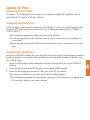
2
Insert the Module
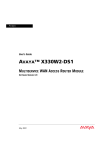
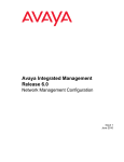
To insert an X330WAN into an Avaya P330 switch:
1. Remove the blanking plate or other expansion module (if installed).
2. Insert the WAN expansion module gently into the slot, ensuring that the Printed Circuit
Board (PCB) is aligned with the guide rails.
3.
4.
5.
L The PCB fits into the guide rails and not the metal base plate.
Press in the expansion module firmly until it is completely inserted into the Avaya P330
switch.
Gently tighten the two screws on the front panel of the expansion module by turning
them.
Power up the Avaya P330 switch.
X The self-test procedure starts. It takes between 30 to 60 seconds to complete.
3
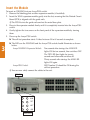
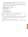
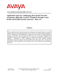
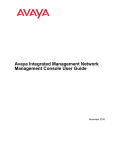
X The LEDs on the X330WAN and the Avaya P330 switch should illuminate as shown
below:
Avaya X330WAN Expansion Module: Ten seconds after startup, the ALM LED
lights ON for ten seconds, then switches OF.F
The TST LED then lights for twenty
seconds and afterwards switches off.
Thirty seconds after startup, the ALM LED
lights ON again.
Avaya P330 Switch:
LED Number 51 should be ON during the
self-test procedure.
L You can now safely connect the cables to the unit.
LED #51
ALM
TST
ACT
SIG
WAN LEDs
Connect the Ports
Connecting the E1/T1 Ports
To connect a T1/E1 module to a network, use a straight-through RJ-48C-to-RJ-48C cable to
connect the E1/T1 port to an RJ-48C wall jack.
Connecting the Ethernet Port
A UTP Category 5 cable must be connected to the 100Base-TX port, via an RJ45 connector. The
maximum UTP cable length connected to the 10/100 Mbps port operating as 10/100Base-T
is 100 m (328 ft.).
LYou can obtain appropriate cables from your local supplier.
LIf you are connecting the Fast Ethernet port to a PC or workstation, you should use a
crossed cable.
LIf you are connecting the Fast Ethernet port to another switch, you should use a straight
cable.
Connecting the Console Port
Each Avaya X330WAN module has one serial port on the front panel for connecting a terminal,
a terminal emulator, or a modem. The serial port on the front panel is labeled “Console” and
has an RJ-45 socket.
1. Insert the RJ-45 plug on the console cable into the Console port of the Avaya X330WAN
module.
2. Insert the other end into the RJ-45 socket in the supplied DB-9 adapter.
3. Insert the DB-9 plug into the serial (COM) port on the PC or terminal.
L To connect a modem, use the cable and an RJ-45 to DB-25 adapter.
L The cable and two adapters can be found in the Avaya P330 accessory set supplied with
P330 switches, and they are clearly marked.
4
Configure the Module
L Before you can set up the X330WAN module you must power on and set up the Avaya
P330 stack as described in the Avaya P330 User’s Guide.
L Before using the X330WAN module you must assign an IP address via the Command
Line Interface (CLI) or via a Telnet session to the switch where the X330 is inserted.
The following steps describe how to configure the X330WAN module using the Avaya CLI.
Establishing a Serial Connection
Perform the following steps to connect a terminal to the Console port of the X330WAN for
configuration of WAN parameters using the CLI:
1. Use the supplied serial cable to attach the RJ-45 console connector to the Console port.
Connect the DB-9 connector to the serial (COM) port on your PC/terminal.
2. Use the following serial port settings on the PC: 9600 baud, 8 bits, 1 stop bit and no parity.
If you connected a PC, run a VT-100 emulation session. (You can use the Windows®
HyperTerminal.)
LThe terminal connected to the serial port must be configured with the same settings; this
setting will work with any PC COM port over a DB9 to RJ45 connector.
3. Press Enter.
4. When prompted for a Login Name, enter the default name root.
5. When promoted for a password, enter the password root.
Establishing a Modem Connection
5
L A PPP connection with a modem can be established only after the X330WAN is configured with an IP address and net-mask. Also, the parameters used in the X330WAN
must be compatible with the remote peer parameters.
L Commands are shown as follows: ip address; parameters which you need to enter
are shown in <> as follows: <net-mask>
LAll CLI commands mentioned in this section are described in the Avaya P330 Reference
Guide.
To configure a modem interface:
1. Connect a terminal to the Console port of the X330WAN as described in “Connecting the
Console Port”.
2. When prompted for a Login Name, enter the default name root and press Enter.
3. When prompted for a password, enter the password root and press Enter. You are now
in Supervisor mode.
4. At the prompt, type: interface Console and press Enter.
5. Use the ip address <ip_addr><net-mask> command entering an IP address and netmask to be used by the remote peer to connect via its console interface to the X330WAN.
6.
LThe console interface configured with the interface Console command must be on
a different subnet from the router interfaces.
Use the following commands to set the baud rate, ppp authentication, ppp chap-secret and
ppp timeout required to match your remote station if they differ from the default values:
LThe default values are shown in bold italic text.
speed <9600 | 19200 | 38400>
ppp authentication <chap |none | pap>
ppp chap-secret <string>
timeout absolute <time>
7.
LThe time is in minutes.
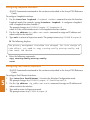
Type: async mode interactive
The following is displayed:
Entering the Modem mode will occur automatically upon
proprietary modem-cable plug-in into the console port.
The terminal mode would be restarted automatically upon
insertion of proprietary terminal-cable.
8.
Use the supplied DB-25 to RJ-45 connector to plug the console cable to the modem’s DB-25
connector. Plug the other end of the cable RJ-45 connector to the Console port on the
X330WAN.
X The X330WAN enters Modem mode within one minute.
You can now dial from a remote station, and open a Telnet session to the IP address configured
in step 5.
5
Configuring Loopback Interfaces
LAll CLI commands mentioned in this section are described in the Avaya P330 Reference
Guide.
To configure Loopback interfaces:
1. Use the interface loopback <loopback number> command to enter the Interface
Loopback mode. For example, typing interface loopback 1 configures a loopback
with a Loopback interface number 1.
The prompt changes to p330WAN-N(super-if:Loopbackn)#
where N is the switch number and n is the loopback interface number.
2. Use the ip address <ip_addr><net-mask> command to assign an IP address and
subnet mask to the interface.
3. Type exit to return to Supervisor mode. The prompt returns to p330WAN-N(super)#.
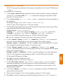
X The following displays:
The primary management interface has changed. For this change to
take effect, you need to copy running-config startup-config and
then reset the device.
4.
Enter the following commands:
copy running-config startup-config
reset
Configuring Fast Ethernet Interfaces
5
LAll CLI commands mentioned in this section are described in the Avaya P330 Reference
Guide.
To configure Fast Ethernet interfaces:
1. Type interface FastEthernet 1 to enter the Interface Configuration mode.
The prompt changes to p330WAN-N(super-if:FastEthernet1)#.
2. Use the ip address <ip_addr><net-mask> command to assign an IP address and
subnet mask to the interface.
3. Type exit to return to Supervisor mode.
The prompt returns to p330WAN-N(super)#.
Configuring E1/T1 Interfaces
LAll CLI commands mentioned in this section are described in the Avaya P330 Reference
Guide.
To configure E1/T1 interfaces:
1. Use the show controllers command to check if your controller’s mode is configured
as E1 or T1. Use the ds1-mode <e1 | t1> command to change the controller’s mode
from E1 to T1 or vice versa.
2. Use the controller <e1 | t1> <port-number> command to set the port number to
be configured.
The prompt changes to p330WAN-N(super-controller:n)#
where N is the switch number and n is the port number.
3. Use the following commands if you want to change the clock source, frame type and linecode parameters from their default settings:
clock source {line | internal}
framing {sf | esf} for T1 lines or framing {crc4 | no-crc4} for E1 lines
linecode {ami|b8zs} for T1 lines or linecode {ami|hdb3} for E1 lines.
For a list of X330WAN default settings, see "X330WAN Default Settings".
4.
5.
X If you are working in E1 mode, go to step 4, otherwise go to step 5.
Use the channel-group channel-no timeslots timeslot-list command to
specify the channel group and time slots to be mapped. For example, typing
channel group 1 timeslots 1,3-5,7 configures time slots numbered 1, 3-5 and 7
to be mapped in channel-group number 1. Proceed to step 6.
Use the channel-group channel-no timeslots timeslot-list speed
<56|64> command to specify the channel group, time slots to be mapped and DS0 speed
in kbps. For example, typing
channel group 1 timeslots 1,3-5,7 speed 64 configures time slots numbered 1,
3-5 and 7 to be mapped in channel-group number 1 and the DS0 speed to 64 kbps.
L The default DS0 speed is 56 kbps
6. Type exit to return to Supervisor mode.
The prompt returns to p330WAN-N(super)#.
7. Use the interface Serial controller[:group-number[.sub-interface]]
command to configure each channel group as a virtual serial interface. For example,
typing interface Serial 1:2 configures a serial interface on port number 1 with
channel group number 2.
8. Use the ip address <ip_addr><net-mask> command to assign an IP address and
subnet mask to the interface.
9. Repeat steps 2 through 7 if you want to configure another T1 or E1 interface.
10. Type exit to return to Supervisor mode.The prompt returns to p330WAN-N(super)#.
5
Changing the Primary Management Interface (pmi).
L The default pmi is the first interface you define.
To change the pmi:
1. Enter one of the interface contexts as explained before.
2. If there no ip assigned on that interface use the |
ip address <ip_ addr>< net- mask> command.
3. Use the ip routing-mode rt_primary_mgmt command to set the interface as pmi.
X The following message displays:
The primary management interface has changed. For this change to
take effect, you need to copy running- config startup- config
and then reset the device
4.
Enter the following commands:
copy running-config startup-config
reset
Establishing a Telnet Connection
Perform the following steps to establish a Telnet connection to the X330WAN for configuration
of WAN parameters. Telnet directly to one of the Router IP addresses:
1. Connect your station to the network.
2. Verify that you can communicate with the X330WAN using the ping command to the IP
address of the X330WAN you chose. If there is no response, check the IP address and
default gateway of both the X330WAN and the station.
3. From the Microsoft Windows® taskbar of your PC, click Start and then Run (or from the
DOS prompt of your PC), then start the Telnet session by typing:
telnet <X330WAN_IP_address>. For example: telnet 149.49.32.134.
5
LYou can also Telnet the IP address of the P330 stack. If you Telnet the IP address of the
stack, a connection is established with the Switch CLI entity of the Master module of the
stack. If you want to connect to the X330WAN CLI entity, use the
session [<mod_num> [wan]] command. If the IP address in the Telnet command is
the address of the X330WAN router, connection is established to the X330WAN CLI
entity.
4. When prompted for a Login Name, enter the default name root.
5. When prompted for a password, enter the User Level password root in lower case letters.
Do NOT use uppercase letters.
You can now configure the X330 WAN.
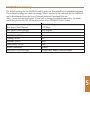
X330WAN Default Settings
The default settings for the X330WAN and its ports are determined by its embedded software.
These default settings are subject to change. Newer versions of the software for the X330WAN
can be downloaded from the Avaya Network Software Download Web site
(http://www.avayanetwork.com). If you wish to change the default parameters, we recommend that you use the CLI. Please refer to the Avaya X330WAN User’s Guide.
Function
Port Speed (Fast Ethernet)
Port Duplex (Fast Ethernet)
Auto Negotiation (Fast Ethernet)
WAN Mode (WAN)
Framing (WAN)
Linecode (WAN)
Clock Source (WAN)
SNMP Community
X330WAN CLI Entry Login
Default Setting
100 Mbps
Full Duplex
Enabled
T1
SF
ami
line
public
Login name: root, Password: root
5
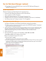
Run the Web-Based Manager (optional)
L To configure the Avaya X330WAN you can use the P330 Web-based Manager in
addition to using the CLI.
System Requirements
Minimum hardware and Operating System requirements are:
• Pentium® II 400 Mhz-based computer with 128 Mb of RAM
• Screen resolution of 1024 x 768 pixels
• Microsoft® Internet Explorer® 5 or Netscape Navigator® 4.x
• Windows® 95, NT® 4.0 (server/workstation) or Windows 2000 (server/workstation)
• Sun Microsystems Java™ plug-in version 1.3.1_02 (supplied)
Running the Embedded Manager
1.
2.
3.
L Assign an IP address to the Master Switch before starting this procedure.
L Assign a primary management interface (pmi) to the X330WAN module. The default
pmi is the first interface you define.
Verify that there is communication between the Master Switch and the X330WAN using
the ping command to the pmi of the X330WAN. If there is no response, check the IP
address and default gateway of both the X330WAN and the Master Switch.
Open your browser.
Enter the URL of the switch in the form http://aaa.bbb.ccc.ddd
L aaa.bbb.ccc.ddd is the IP address of the switch.
X You are prompted to log into the switch.
L The user name is root.
The default password for read-write access is root.
L The Web management passwords are the same as those of the CLI. If you have created
additional CLI user names or changed the default passwords then you can use those
passwords for Web management as well.
X The welcome page is displayed.
6
•
•
•
L If the network manager has configured the system the plug-in should be installed automatically.
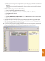
If the plug-in is not installed automatically, there are three ways to install the plug-in
manually:
Either install the plug-in from the CD as follows:
1. Close all unnecessary applications on your PC.
2. Insert the “Avaya P330 Documentation and Utilities” CD in the CD drive.
3. Click Start on the Task bar.
4. Select Run.
5. Type x:\emweb-aux-files\plugin_1_3_1.exe (where x: is the CD drive letter)
6. Follow the on-screen instructions.
Or install the plug-in from the Avaya site by clicking on the link on the welcome page.
Or, if the network manager has placed the files on the local site, install the plug-in from
there by clicking the link on the welcome page.
X If you have the Java plug-in already installed or once you have successfully installed the
plug-in as described above, the Web-based manager opens in your browser.
6
Documentation and Online Help
Refer to the Avaya X330WAN Documentation and Utilities CD for full instructions.
Notes
Contact Information
To contact Avaya technical support:
From the United States:
Please call 1-800-237-0016, press 0, then press 73300.
From outside the United States:
EMEA (Europe, Middle East and Africa). Email: [email protected]
AP (Asia Pacific). Email: [email protected]
Country
Local Dial-In Number
Albania
+31 70 414 8001
Austria
+43 1 36 0277 1000
Azerbaijan
+31 70 414 8047
Bahrain
+800 610
Belgium
+32 2 626 8420
Belorussia
+31 70 414 8047
Bosnia Herzegovina +31 70 414 8042
Bulgaria
+31 70 414 8004
Croatia
+31 70 414 8039
Cyprus
+31 70 414 8005
Czech Rep.
+31 70 414 8006
Denmark
+45 8233 2807
Egypt
+31 70 414 8008
Estonia
+372 6604736
Finland
+358 981 710 081
France
+33 1 4993 9009
Germany
+49 69 95307 680
Ghana
+31 70 414 8044
Gibraltar
+31 70 414 8013
Greece
+00800 3122 1288
Hungary
+06800 13839
Iceland
+0800 8125
Country
Ireland
Israel
Italy
Jordan
Kazakhstan
Kenya
Kuwait
Latvia
Lebanon
Lithuania
Luxemburg
Macedonia
Malta
Mauritius
Morocco
Netherlands
Nigeria
Norway
Oman
Pakistan
Poland
Local Dial-In Number
+353 160 58 479
+1 800 93 00 900
+39 02 7541 9636
+31 70 414 8045
+31 70 414 8020
+31 70 414 8049
+31 70 414 8052
+371 721 4368
+31 70 414 8053
+370 2 756 800
+352 29 6969 5624
+31 70 414 8041
+31 70 414 8022
+31 70 414 8054
+31 70 414 8055
+31 70 414 8023
+31 70 414 8056
+47 235 001 00
+31 70 414 8057
+31 70 414 8058
+0800 311 1273
Country
Qatar
Portugal
Romania
Russia
Saudi Arabia
Slovakia
Slovenia
South Africa
Spain
Sweden
Switzerland
Tanzania
Tunisia
Turkey
Uganda
Ukraine
UAE
UK
Uzbekistan
Yemen
Yugoslavia
Zimbabwe
Local Dial-In Number
+31 70 414 8059
+351 21 318 0047
+31 70 414 8027
+7-095-733-9055
+31 70 414 8022
+31 70 414 8066
+31 70 414 8040
+0800 995 059
+34 91 375 3023
+46 851 992 080
+41 22 827 8741
+31 70 414 8060
+31 70 414 8069
+800 4491 3919
+31 70 414 8061
+31 70 414 8035
+31 70 414 8036
+44 0207 5195000
+31 70 414 8046
+31 70 414 8062
+31 70 414 8038
+31 70 414 8063
CALA (Caribbean and Latin America). Email: [email protected]
Country
Australia
Hong Kong
Indonesia
Japan
Local Dial-In Number
+1800 255 233
+2506 5451
+800 1 225 227
+0 120 766 227
Country
Korea
Malaysia
New Zealand
Local Dial-In Number
+0 80 766 2580
+1800 880 227
+00 800 9828 9828
Country
Philippines
Singapore
Taiwan
Local Dial-In Number
+1800 1888 7798
+1800 872 8717
+0 80 025 227
Hot Line: +1 720 4449 998
Fax:
+1 720 444 9103
L For updated information, visit www.avaya.com/support
avaya.com
All trademarks, registered trademarks, service names, product and/or brand names are the sole property of their respective owners.
Copyright © 2002, Avaya Inc. All rights reserved.
Catalog No. DO0648 Rev. 0.
May 2002