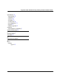
1
Avaya SG5, SG5X, and SG200
Security Gateway
Hardware Installation Guide
670-100-102
Issue 2
March 2004
Copyright 2004, Avaya Inc.
All Rights Reserved
Notice
Every effort was made to ensure that the information in this
document was complete and accurate at the time of release.
However, information is subject to change.
Warranty
Avaya Inc. provides a limited warranty on this product. Refer
to your sales agreement to establish the terms of the limited
warranty. In addition, Avaya’s standard warranty language as
well as information regarding support for this product, while
under warranty, is available through the following website:
http://www.avaya.com/support
Preventing Toll Fraud
“Toll fraud” is the unauthorized use of your
telecommunications system by an unauthorized party (for
example, a person who is not a corporate employee, agent,
subcontractor, or is not working on your company's behalf).
Be aware that there may be a risk of toll fraud associated with
your system and that, if toll fraud occurs, it can result in
substantial additional charges for your telecommunications
services.
Avaya Fraud Intervention
If you suspect that you are being victimized by toll fraud and
you need technical assistance or support, in the United
States and Canada, call the Technical Service Center's Toll
Fraud Intervention Hotline at 1-800-643-2353.
Providing Telecommunications Security
Telecommunications security (of voice, data, and/or video
communications) is the prevention of any type of intrusion to
(that is, either unauthorized or malicious access to or use of)
your company's telecommunications equipment by some
party.
Your company's “telecommunications equipment” includes
both this Avaya product and any other voice/data/video
equipment that could be accessed via this Avaya product
(that is, “networked equipment”).
An “outside party” is anyone who is not a corporate
employee, agent, subcontractor, or is not working on your
company's behalf. Whereas, a “malicious party” is anyone
(including someone who may be otherwise authorized) who
accesses your telecommunications equipment with either
malicious or mischievous intent.
Such intrusions may be either to/through synchronous (timemultiplexed and/or circuit-based) or asynchronous
(character-, message-, or packet-based) equipment or
interfaces for reasons of:
• Utilization (of capabilities special to the accessed
equipment)
• Theft (such as, of intellectual property, financial assets, or
toll-facility access)
• Eavesdropping (privacy invasions to humans)
• Mischief (troubling, but apparently innocuous, tampering)
• Harm (such as harmful tampering, data loss or alteration,
regardless of motive or intent)
Disclaimer
Avaya is not responsible for any modifications, additions or
deletions to the original published version of this
documentation unless such modifications, additions or
deletions were performed by Avaya. Customer and/or End
User agree to indemnify and hold harmless Avaya. Avaya’s
agents, servants and employees against all claims, lawsuits,
demands and judgements arising out of, or in connection
with, subsequent modifications, additions or deletions to this
documentation to the extent made by the Customer or End
User.
How to Get Help
For additional support telephone numbers, go to the Avaya
Web site: http://www.avaya.com/support/. If you are:
• Within the United States, click Escalation Management
link. Then click the appropriate link for the type of support
you need.
• Outside the United States, click Escalation Management
link. Then click International Services link that includes
telephone numbers for the International Centers of
Excellence.
Be aware that there may be a risk of unauthorized intrusions
associated with your system and/or its networked equipment.
Also realize that, if such an intrusion should occur, it could
result in a variety of losses to your company (including but
not limited to, human/data privacy, intellectual property,
material assets, financial resources, labor costs, and/or legal
costs).
Responsibility for Your Company’s Telecommunications
Security
The final responsibility for securing both this system and its
networked equipment rests with you - Avaya’s customer
system administrator, your telecommunications peers, and
your managers. Base the fulfillment of your responsibility on
acquired knowledge and resources from a variety of sources
including but not limited to:
• Installation documents
• System administration documents
• Security documents
• Hardware-/software-based security tools
• Shared information between you and your peers
• Telecommunications security experts
To prevent intrusions to your telecommunications equipment,
you and your peers should carefully program and configure:
• Your Avaya-provided telecommunications systems and
their interfaces
• Your Avaya-provided software applications, as well as
their underlying hardware/software platforms and
interfaces
• Any other equipment networked to your Avaya products.
TCP/IP Facilities
Customers may experience differences in product
performance, reliability and security depending upon network
configurations/design and topologies, even when the product
performs as warranted.
Standards Compliance
Avaya Inc. is not responsible for any radio or television
interference caused by unauthorized modifications of this
equipment or the substitution or attachment of connecting
cables and equipment other than those specified by Avaya
Inc. The correction of interference caused by such
unauthorized modifications, substitution or attachment will be
the responsibility of the user. Pursuant to Part 15 of the
Federal Communications Commission (FCC) Rules, the user
is cautioned that changes or modifications not expressly
approved by Avaya Inc. could void the user’s authority to
operate this equipment.
Product Safety Standards
This product complies with and conforms to the following
international Product Safety standards as applicable:
• Safety of Information Technology Equipment, IEC 60950,
3rd Edition including all relevant national deviations as
listed in Compliance with IEC for Electrical Equipment
(IECEE) CB-96A.
• Safety of Information Technology Equipment, CAN/CSAC22.2 No. 60950-00 / UL 60950, 3rd Edition
• Safety Requirements for Customer Equipment, ACA
Technical Standard (TS) 001 - 1997
• One or more of the following Mexican national standards,
as applicable: NOM 001 SCFI 1993, NOM SCFI 016
1993, NOM 019 SCFI 1998
Electromagnetic Compatibility (EMC) Standards
This product complies with and conforms to the following
international EMC standards and all relevant national
deviations:
Limits and Methods of Measurement of Radio Interference of
Information Technology Equipment, CISPR 22:1997 and
EN55022:1998.
Information Technology Equipment – Immunity
Characteristics – Limits and Methods of Measurement,
CISPR 24:1997 and EN55024:1998, including:
•
•
•
•
•
•
•
•
•
Electrostatic Discharge (ESD) IEC 61000-4-2
Radiated Immunity IEC 61000-4-3
Electrical Fast Transient IEC 61000-4-4
Lightning Effects IEC 61000-4-5
Conducted Immunity IEC 61000-4-6
Mains Frequency Magnetic Field IEC 61000-4-8
Voltage Dips and Variations IEC 61000-4-11
Powerline Harmonics IEC 61000-3-2
Voltage Fluctuations and Flicker IEC 61000-3-3
Federal Communications Commission Statement
Part 15:
Note: This equipment has been tested and found to comply
with the limits for a Class A digital device, pursuant to Part
15 of the FCC Rules. These limits are designed to provide
reasonable protection against harmful interference when the
equipment is operated in a commercial environment. This
equipment generates, uses, and can radiate radio frequency
energy and, if not installed and used in accordance with the
instruction manual, may cause harmful interference to radio
communications. Operation of this equipment in a residential
area is likely to cause harmful interference in which case the
user will be required to correct the interference at his own
expense.
Canadian Department of Communications (DOC)
Interference Information
This Class A digital apparatus complies with Canadian ICES003.
Cet appareil numérique de la classe A est conforme à la
norme NMB-003 du Canada.
This equipment meets the applicable Industry Canada
Terminal Equipment Technical Specifications. This is
confirmed by the registration number. The abbreviation, IC,
before the registration number signifies that registration was
performed based on a Declaration of Conformity indicating
that Industry Canada technical specifications were met. It
does not imply that Industry Canada approved the
equipment.
DECLARATIONS OF CONFORMITY
United States FCC Part 68 Supplier’s Declaration of
Conformity (SDoC)
Avaya Inc. in the United States of America hereby certifies
that the equipment described in this document and bearing a
TIA TSB-168 label identification number complies with the
FCC’s Rules and Regulations 47 CFR Part 68, and the
Administrative Council on Terminal Attachments (ACTA)
adopted technical criteria.
Avaya further asserts that Avaya handset-equipped terminal
equipment described in this document complies with
Paragraph 68.316 of the FCC Rules and Regulations
defining Hearing Aid Compatibility and is deemed compatible
with hearing aids.
Copies of SDoCs signed by the Responsible Party in the U.
S. can be obtained by contacting your local sales
representative and are available on the following Web site:
http://www.avaya.com/support
All Avaya media servers and media gateways are compliant
with FCC Part 68, but many have been registered with the
FCC before the SDoC process was available. A list of all
Avaya registered products may be found at:
http://www.part68.org/
by conducting a search using “Avaya” as manufacturer.
China
BMSI (Chinese Warning Label)
Hardware, including technical data, is subject to U.S. export
control laws, including the U.S. Export Administration Act and
its associated regulations, and may be subject to export or
import regulations in other countries. Customer agrees to
comply strictly with all such regulations and acknowledges
that it has the responsibility to obtain licenses to export, reexport, or import hardware.
Environmental Health and Safety:
European Union Declarations of Conformity
! WARNING:
Avaya Inc. declares that the equipment specified in this
document bearing the “CE” (Conformité Europeénne) mark
conforms to the European Union Radio and
Telecommunications Terminal Equipment Directive (1999/5/
EC), including the Electromagnetic Compatibility Directive
(89/336/EEC) and Low Voltage Directive (73/23/EEC). This
equipment has been certified to meet CTR3 Basic Rate
Interface (BRI) and CTR4 Primary Rate Interface (PRI) and
subsets thereof in CTR12 and CTR13, as applicable.
Copies of these Declarations of Conformity (DoCs) can be
obtained by contacting your local sales representative and
are available on the following Web site:
http://www.avaya.com/support
Japan
This is a Class A product based on the standard of the
Voluntary Control Council for Interference by Information
Technology Equipment (VCCI). If this equipment is used in a
domestic environment, radio disturbance may occur, in which
case, the user may be required to take corrective actions.
Risk of explosion if battery is replaced by an incorrect type.
Dispose of used batteries according to Avaya Environmental
Health and Safety guidelines.
Documentation:
For the most current versions of documentation, go to the
Avaya support Web site: http://www.avaya.com/support/
Table of Content
About this book
7
Contacting technical support . . . . . . . . . . . . . . . . . . . . . . . . . . . . . . . . . . . . . . . . . 7
Documentation . . . . . . . . . . . . . . . . . . . . . . . . . . . . . . . . . . . . . . . . . . . . . . . . . . . . 8
Chapter 1
Introduction
9
Functional overview . . . . . . . . . . . . . . . . . . . . . . . . . . . . . . . . . . . . . . . . . . . . . . . . 9
Security . . . . . . . . . . . . . . . . . . . . . . . . . . . . . . . . . . . . . . . . . . . . . . . . . . . . . . 10
Plug-and-play installation . . . . . . . . . . . . . . . . . . . . . . . . . . . . . . . . . . . . . . . . 11
Hardware components . . . . . . . . . . . . . . . . . . . . . . . . . . . . . . . . . . . . . . . . . . . . . 12
Available ports . . . . . . . . . . . . . . . . . . . . . . . . . . . . . . . . . . . . . . . . . . . . . . . . . 13
Chapter 2
Installing the security gateway
General requirements . . . . . . . . . . . . . . . . . . . . . . . . . . . . . . . . . . . . . . . . . . . . . .
Environmental requirements . . . . . . . . . . . . . . . . . . . . . . . . . . . . . . . . . . . . . .
Power considerations . . . . . . . . . . . . . . . . . . . . . . . . . . . . . . . . . . . . . . . . . . . .
Equipment required . . . . . . . . . . . . . . . . . . . . . . . . . . . . . . . . . . . . . . . . . . . . .
System requirements . . . . . . . . . . . . . . . . . . . . . . . . . . . . . . . . . . . . . . . . . . . .
Installing the security gateway . . . . . . . . . . . . . . . . . . . . . . . . . . . . . . . . . . . . . . .
Chapter 3
Setting up the security gateway for configuration
Service provider provisioning . . . . . . . . . . . . . . . . . . . . . . . . . . . . . . . . . . . . . . .
Power on self-test . . . . . . . . . . . . . . . . . . . . . . . . . . . . . . . . . . . . . . . . . . . . . . . . .
Connecting to the private port of the security gateway . . . . . . . . . . . . . . . . . . . .
Performing the quick setup. . . . . . . . . . . . . . . . . . . . . . . . . . . . . . . . . . . . . . . . . .
March 2004
15
15
15
16
16
16
17
23
24
24
25
25
5
Avaya SG5, SG5X, & SG200 Security Gateway Hardware Installation Guide
Appendix A
Specifications
Physical specifications. . . . . . . . . . . . . . . . . . . . . . . . . . . . . . . . . . . . . . . . . . . . . .
Environmental specifications . . . . . . . . . . . . . . . . . . . . . . . . . . . . . . . . . . . . . . . .
Electrical specifications . . . . . . . . . . . . . . . . . . . . . . . . . . . . . . . . . . . . . . . . . . . . .
Compliance specifications . . . . . . . . . . . . . . . . . . . . . . . . . . . . . . . . . . . . . . . . . . .
Additional features . . . . . . . . . . . . . . . . . . . . . . . . . . . . . . . . . . . . . . . . . . . . . . . .
Index
6
29
30
30
31
32
33
March 2004
About this book
Avaya SG5, SG5X, and SG200 is the new name for Avaya VSU5,
VSU5X, and VSU 500 Security Gateways. Our documentation reflects
these new names as of June, 2003.
This guide describes the Avaya SG5, the SG5X, and the SG200 Security
Gateways and how to install and preconfigure these devices. It is
recommended that you read the entire installation guide before installing
the security gateway.
Contacting technical support
Technical support is available to registered users of the Avaya security
gateway products.
Domestic support
• Toll free phone support: (866) 462-8292 (24x7)
• Email: [email protected]
• Web: http://support.avaya.com
International support
• For regional support numbers, go to http://www.avayanetwork.com/
site/GSO/default.htm
March 2004
About this book 7
Avaya SG5, SG5X, & SG200 Security Gateway Hardware Installation Guide
Documentation
The security gateway documentation includes both the Hardware
Installation Guide and the Security Gateway Configuration Guide for
VPNos. You can down load these guides from
http://support.avaya.com. Navigate to Product Documentation, VPN and
Security.
8 About this book
March 2004
Chapter 1
Introduction
Functional overview
The Avaya SG5, SG5X, and SG200 security gateways are VPN
gateways to virtual private networks (VPNs) for small business and home
office users. The security gateway allows users to connect securely to
their corporate networks and intranets through always-on connections
such as DSL and cable modems. Designed to provide the convenience of
a firewall and a gateway all in one compact desktop enclosure, the
security gateway provides a cost-effective solution to quick and easy VPN
deployment while providing strong attack prevention mechanisms against
common attacks and Internet security threats.
The SG5X and the VSU200 are functionally identical to the SG5, but the
VSU5X includes an integrated 7-port Ethernet switch. The VSU200
introduces a cardbus/PCMCIA expansion slot for future functionality,
routing capabilities, and firewall enhancements that can be managed
from a central-site location.
Like other platforms in the Avaya VPN family, the security gateway adds
encryption, authentication, and key management to public network data
links to ensure privacy and integrity of corporate data, and to enable the
efficient and secure operation of VPNs. It is designed to perform complex
operations, in real time, without compromising network performance.
The security gateway supports a full suite of VPN services including:
IPsec-based encryption, packet authentication, and IKE key
management, Network Address Translation (NAT), and packet filtering.
March 2004
Introduction 9
Avaya SG5, SG5X, & SG200 Security Gateway Hardware Installation Guide
Figure 1 SG200 security gateway
Security
The VSU provides data stream privacy by employing cryptographic
algorithms and keys powerful enough for the most sensitive business
communications. It supports DES and 3DES encryption, as well as the
IKE key management standards.
Data authenticity is assured by using MD5™ or SHA-1 hashing algorithms
to reject altered or forged packets. All security mechanisms employed by
the security gateway conform to IPsec standards, in order to provide
interoperability and broaden the use of VPN technology.
The security gateway also contains a powerful IP packet filtering engine
to provide extensive filtering capabilities, essential when you have a fulltime connection to the Internet. A rule-based method of packet filtering is
used, where the priority of the rule is determined by its position in the list
(highest is top priority).
10 Introduction
March 2004
Avaya SG5, SG5X, & SG200 Security Gateway Hardware Installation Guide
Plug-and-play installation
The security gateway can be placed anywhere in a 10/100BASE-T LAN
to provide VPN functionality. Native support for IP ensures that the
security gateway interoperates transparently with the broadest range of
intranet and other network applications.
Affording fast and easy installation into your new or existing local area
network, the security gateway functions as a DHCP server on its private
port, supporting VPNs and remote access users. This greatly minimizes
the necessary configuration of your workstations and IP devices. The
security gateway’s web-based user interface features a quick setup
wizard designed to capture essential configuration information for easy
initial setup. Provisions are also made to access the web-based interface
remotely over the Internet if desired.
Where central management of your VPN is required, the optional Avaya
VPNmanager network management application (available separately)
steps network managers through the setup process and allows them to
configure a VPN in minutes. The VPNmanager also supports extensive
facilities for VPN monitoring and troubleshooting, and for establishing
multi-company extranets.
March 2004
Introduction 11
Avaya SG5, SG5X, & SG200 Security Gateway Hardware Installation Guide
Hardware components
Figure 2 displays the back panel components on each of the security
gateways.
Figure 2 Back panel components
Public Port
SG5
Private Port
Ethernet Ports
Status Indicators
Reset Switch
Access
DC Power
Connector
Private Ports
SG5X
Public Port
Console Port
Private Port
Interface Expansion Card/Slot
SG200
12 Introduction
March 2004
Avaya SG5, SG5X, & SG200 Security Gateway Hardware Installation Guide
Available ports
The SG5 includes two 10/100BASE-T Ethernet ports that includes a
public and private interface port. The SG5X includes one 10/100BASE-T
Ethernet port on the public interface, and 7 10/100BASE-T Ethernet ports
on the private interface. The SG200 includes two 10/100BASE-T Ethernet
ports that includes a public and private interface port, RS-232 console
port, and a PC Card Netgear (PCMCIA) expansion port.
Table 1
Network zones
Media type
SG5
SG5X
SG200
Ethernet0
Public
Public
Public
Ethernet1
Private
Private
Private
Ethernet2
(Expansion)
NA
NA
• Public
backup
• Semiprivate
• DMZ
• Management
The status indication of the LEDs on the Ethernet ports are shown in
Figure 2.
March 2004
Introduction 13
Avaya SG5, SG5X, & SG200 Security Gateway Hardware Installation Guide
14 Introduction
March 2004
Chapter 2
Installing the security gateway
General requirements
This section describes the requirements your site must meet for safe
installation and operation of your system. Ensure that you are properly
prepared before beginning installation.
Environmental requirements
The security gateway is intended for use in a normal home office
environment. For more extreme conditions, verify that temperature,
humidity, and power conditions meet the specifications indicated in
Table 2.
Table 2
Environmental requirements
Item
Operating Specification
Temperature
32° to 104° F, 0° to 40°C
Relative Humidity
5-90%, non-condensing
Altitude
0-12,000 feet, 0-3,660 meters
Voltage
100-240 VAC
Input Frequency
47-63 Hz
AC input current
0.4 Amp
Additional security gateway specifications are included in Appendix A.
March 2004
Installing the security gateway 15
Avaya SG5, SG5X, & SG200 Security Gateway Hardware Installation Guide
Power considerations
Be sure that the power where the security gateway will be used is “clean”
power (free of spikes and noise). Install a power conditioner if necessary.
WARNING: This product relies on the building’s installation for shortcircuit (overcurrent) protection. Ensure that a fuse or circuit breaker no
larger than 120 VAC, 15A U.S. (240 VAC, 10A international) is used on
the phase conductor (all current-carrying conductors).
Equipment required
The VSU shipping carton should contain:
Quantit
y
Part Description
1
Security Gateway VPN Service Unit
1
DC Power Supply
1
UTP Crossover Cable
1
Power cord (110V) or
Power cord (230V)
4
Rubber feet for desktop installations
System requirements
Before you begin the installation process, confirm the following items are
available on your local network:
• A router, DSL, cable or ISDN modem, providing connectivity to a WAN
such as the Internet
• 10/100BASE-T Ethernet hub, router, or switch providing connectivity to
a LAN
• CAT 3, 4, or 5 UTP cable to interconnect router, VSU, and hub(s)
• A Java-enabled (JDK 1.1.8 or later) 128-bit encryption-capable
browser such as Internet Explorer 5.5 (or later) or Netscape 6.2 (or
later) installed on each workstation on your LAN that will communicate
with the security gateway.
16 Installing the security gateway
March 2004
Avaya SG5, SG5X, & SG200 Security Gateway Hardware Installation Guide
Installing the security gateway
Figure 3 shows a typical network using the SG5 security gateway.
Figure 3 Typical SG5 installation
SG5
March 2004
Installing the security gateway 17
Avaya SG5, SG5X, & SG200 Security Gateway Hardware Installation Guide
Figure 4 shows a typical network using the SG5X security gateway.
Figure 4 Typical SG5X installation
SG5X
18 Installing the security gateway
March 2004
Avaya SG5, SG5X, & SG200 Security Gateway Hardware Installation Guide
Figure 5 shows a typical network using the SG200 security gateway.
Figure 5 Typical SG200 installation
SG200
March 2004
Installing the security gateway 19
Avaya SG5, SG5X, & SG200 Security Gateway Hardware Installation Guide
Figure 6 Security gateway rear panel connectors
Connect Cable between the
SG5/5X Private Port and Hub or Workstation
Connect Cable between the SG5/5X
Public Port and the DSL/Cable Modem
Connect Cable between the
SG200 Private Port and Hub or Workstation
Connect Cable between the SG200
Public Port and the DSL/Cable Modem
20 Installing the security gateway
March 2004
Avaya SG5, SG5X, & SG200 Security Gateway Hardware Installation Guide
The public port provides an Ethernet interface to the public network
(through a DSL or cable modem), while the private port(s) connect to your
local network, (typically through a hub in the case of the SG5).
All Ethernet ports are 10/100BASE-T compliant host ports. They accept
category 3, 4, or 5 UTP cabling terminated in an RJ-45 connector per
IEEE 802.3 requirements for 10BASE-T.
Perform the following steps to install the security gateway in a typical
LAN:
1.
Using a standard Ethernet cable, connect the VSU public port to your
DSL or cable modem.
2.
Connect the private port of the SG5 security gateway to your hub, or in
the case of a single user, to your workstation’s Ethernet LAN
connector.
For the SG5X security gateway, connect the private port to your
workstations or IP devices on your LAN. If you’re attaching IP
telephones, connect them to the private ports as well.
3.
Connect the power cable from the power supply to the VSU, then
connect the power supply to an AC outlet.
Use the retaining clip provided to secure the power cable to the rear of
the security gateway. This prevents the power connector from
accidental disconnect.
Figure 7 Connecting the DC power supply
Retaining Clip
4.
March 2004
Proceed to Chapter 3, Setting up the security gateway for
configuration.
Installing the security gateway 21
Avaya SG5, SG5X, & SG200 Security Gateway Hardware Installation Guide
22 Installing the security gateway
March 2004
Chapter 3
Setting up the security gateway
for configuration
This chapter describes how to set up the security gateway addressing
and remote connectivity capabilities in preparation for remote
configuration using the VPNmanager software. This preliminary
configuration is performed using a browser on your workstation
connected to the security gateway’s Private Port. The following procedure
assumes that the security gateway has been physically installed on the
network, according to the instructions provided in Chapter 2.
The security gateway setup consists of two basic steps:
• Establishing connectivity between the workstations or IP devices on
your local network with the security gateway’s Private Port(s),
• Setting up the security gateway’s Public Port to reach the Internet.
When the security gateway is initially installed and connected to your
local LAN, it is provisioned with a default IP address for the DHCP server
(serving the Private Ports) allowing you to access the device through a
web browser on your workstation. Through the web interface, you can
assign a static IP address for the Public Port, password, etc. Once this
has been done, the security gateway can be incorporated into your Virtual
Private Network (VPN) by your VPN administrator using remote
configuration software from a central location.
March 2004
Setting up the security gateway for configuration 23
Avaya SG5, SG5X, & SG200 Security Gateway Hardware Installation Guide
Service provider provisioning
Your Connection Type
Before you begin, you will need to determine if your existing installation
uses static IP addresses, dynamic addressing (DHCP), or PPPoE from
your service provider. Typically, DSL connections use PPPoE and cable
modems use DHCP.
Your network administrator can provide you with the information you will
need to complete a Quick Setup. You should have this information on
hand before you begin the setup procedure.
IP telephony considerations
For a VoIP connection through a SG5X, a DSL or cable modem
connection is required for an acceptable voice quality. As voice traffic is
highly sensitive to delay, the quality of the connection depends on the
available bandwidth at the time the call is made. The actual available
bandwidth may vary significantly depending on the time of day, the
number of simultaneous users, and also differs from ISP to ISP. If the
SG5X deployment is in a business environment, such as a small office, a
Service Level Agreement (SLA) with the service provider can ensure
business quality VoIP connections.
Up to eight IP telephones can be connected behind the SG5X, depending
on network connectivity.
Power on self-test
After confirming that your connections are correct, apply power to the
security gateway.
A power-on self test (POST) occurs as soon as power is applied to the
security gateway. This test is designed to verify that all security gateway
major components are functioning properly. A successfully completed test
results in both the VPN and LAN LEDs (on the top of the unit) being off.
Boot-up hardware errors are signalled by LED blink codes. Upon a startup
failure, both the VPN Traffic LED and the LAN Traffic LED simultaneously
blink error codes. Refer to Appendix B for a list of these codes.
24 Setting up the security gateway for configuration
March 2004
Avaya SG5, SG5X, & SG200 Security Gateway Hardware Installation Guide
Connecting to the private port of the security gateway
From the workstation’s control panel, select your TCP/IP network
component for your Ethernet controller. In the IP Address window select
“enable the setting” to “Obtain an IP address automatically” .
Restart your workstation if the operating system asks you to do so. As
your workstation restarts, it automatically obtains its required IP address/
mask, and default router IP address from the security gateway.
NOTE: Unless you have other DNS servers at your local site, it is
recommended that the Windows DNS and WINS server lists be empty.
The DNS server built into the security gateway should normally be the
sole DNS server that users see.
Performing the quick setup
Quick Setup collects and preconfigures the essential information required
to remotely configure and manage the security gateway.
Note: If the security gateway is to be configured and managed locally,
see the Security Gateway Configuration Guide for the VPNos, to perform
a comprehensive device configuration.
The Quick Setup wizard collects the necessary information to
communicate with the remote VPNmanager application through the
security gateway’s public port. The following information is required to
complete the quick setup:
• The type of addressing to be used on the security gateway’s public
port, either Static IP Addressing, Dynamic Addressing (DHCP), or
PPPoE. Typically, DSL connections use PPPoE and cable modems
use DHCP. The default is DHCP
• A network mask for the above
• A default route. This is the service provider’s router used only if Static
IP Address is selected
• The user name and password, if your connection to your ISP is PPPoE
If you are unsure of any of these items, your network administrator should
be able to furnish these values to you.
March 2004
Setting up the security gateway for configuration 25
Avaya SG5, SG5X, & SG200 Security Gateway Hardware Installation Guide
To connect to the security gateway
1.
From a workstation on the private side of the security gateway, open
your browser and type into the location field one of the following:
• https://sg.private
• https://192.168.1.1 (security gateway default address)
2.
Click Yes to accept the security alert message.
The security gateway Login window is displayed.
Figure 8 Security gateway login screen
3.
Enter the User name root, and the Password enter password.
Click Log In.
4.
The first time you connect to the security gateway, two sequential popup messages appear over the main screen. The first is a password
change alert that advises you to change the factory default password.
Change the default password to a secure password.
5.
The next alert message indicates that the security gateway has not yet
been configured. Click OK to launch the Quick Setup wizard.
6.
The Quick Setup wizard dialog is displayed.
26 Setting up the security gateway for configuration
March 2004
Avaya SG5, SG5X, & SG200 Security Gateway Hardware Installation Guide
Figure 9 Quick setup dialog
In the IP Configuration area, select one of the following IP Config
Modes.
• Static Addressing. If you are going to use static addressing on the
public port, click the Static Addressing radio button and enter your
IP address, network mask, and default route information.
• DHCP. If you plan to use DHCP, the public port automatically
obtains its address from a DHCP server. This method is typical for
cable modem connections.
7.
Depending on the IP config mode selected, complete the fields that
populate the dialog.
• For Static, enter the IP address, mask and route
• For PPPoE, enter the user name and password
March 2004
Setting up the security gateway for configuration 27
Avaya SG5, SG5X, & SG200 Security Gateway Hardware Installation Guide
8.
In the Centralized Management area, if VPNmanager is used, enter
the Super User name superuser and Password enter password.
Superuser and password are the default Super User name and
Password for Centralized Management. If the Super User and
Password are changed, be sure to change the defaults to a secure
user name and password and make note of the change as this
information is required to send updates from VPNmanager.
9.
In the Date & Time area, enter the date, time, and time zone.
A 24-hour clock is used. For example, 13:00:00 is equivalent to
1:00 PM.
10.
Click Save and then click Log Out from the main page to log of the
Web interface.
NOTE: When you use Log out, you are prompted to save any unsaved
changes before exiting. If you close your browser, unsaved changes are
lost.
You now have entered enough information to allow the security gateway
to be accessed over the Internet. The remaining configuration process
can be completed remotely, using VPNmanager, or if the security
gateway is managed locally, you can continue the configuration. Refer to
the Security Gateway Configuration Guide for VPNos 4.3.
28 Setting up the security gateway for configuration
March 2004
Appendix A Specifications
This appendix provides physical, environmental and electrical
specifications for the security gateway, as well as standards compliance
information.
Physical specifications
Table 3
Physical specifications
Parameter
SG5
SG5X
SG200
Dimensions
6.0" W x 5.0" D x 1.5" H
(15.24 x 12.7 x 3.82cm)
7.75" W x 6.5" D x 1.9" H
(19.6 x 16.5 x 4.8 cm)
7.75" W x 6.5" D x 2.5" H
(19.6 x 16.5 x 6.4 cm)
Weight
10 ounces (283.5 grams)
16 ounces (497 grams)
16 ounces (497 grams)
LAN
Interface
One 10/100BASE-T
Ethernet port
Seven 10/100BASE-T
Ethernet ports
Two 10/100BASE-T
Ethernet ports
Management
Interfaces
One 10/100BASE-T
Ethernet port
One 10/100BASE-T
Ethernet port
One 10/100BASE-T
Ethernet port, One RS-232
March 2004
Specifications 29
Avaya SG5, SG5X, & SG200 Security Gateway Hardware Installation Guide
Environmental specifications
Table 4
Environmental specifications
Parameter
Operating
Specification
Temperature
32-104°F, 0-40°C
Relative Humidity
5-90%, non-condensing
Altitude
0-12,000 feet, 0-3,660 meters
Electrical specifications
Table 5
Electrical specifications
Parameter
SG5
SG5X
SG200
90-264 VAC
90-264 VAC
90-264 VAC
Input
Frequency
50-60 Hz
50-60 Hz
50-60 Hz
AC input
current
2.3A max. (100-240VAC)
2.3A max. (100-240VAC)
2.3A max. (100-240VAC)
DC Input
+5.0 VDC 5%, 6 watts max.
+5.0 VDC 5%, 10 watts max.
+5.0 VDC 5%, 15 watts max.
Internal
Battery
Memory backup (see
Caution below)
Memory backup (see
Caution below)
Memory backup (see
Caution below)
AC Adapter
Voltage
CAUTION: Danger of explosion if memory backup battery is incorrectly
replaced. Replace only with the same or equivalent type recommended
by the manufacturer. Dispose of used batteries according to the
manufacturer’s instructions. Note that the battery in this unit is a nonserviceable part.
30 Specifications
March 2004
Avaya SG5, SG5X, & SG200 Security Gateway Hardware Installation Guide
Compliance specifications
Table 6
March 2004
Compliance specifications
Parameter
Specification
Safety
Certification
CSA, CE, CB SCHEME, EN, C-Tick Mark
EMI/RFI
FCC Part 15, Class B,
EN55022 Class B
EN50082-1
VCCI
BSMI
Standards
Compliance
IEEE 802.3, Ethernet
IPsec Compliance:
RFC 2401Security Architecture for the Internet Protocol
RFC 2402IP Authentication Header
RFC 2403The Use of HMAC-MD5-96 within ESP and
AH
RFC 2404The Use of HMAC-SHA-1-96 within ESP and
AH
RFC 2405The ESP DES-CBC Cipher Algorithm with
Explicit IV
RFC 2406 IP Encapsulating Security Payload
RFC 2407Internet IP Security Domain of Interpretation
for ISAKMP
RFC 2408Internet Security Association and Key
Management (ISAKMP)
RFC 2409Internet Key Exchange (IKE)
RFC 2410The NULL Encryption Algorithm and Its Use
with IPsec
RFC 2412The OAKLEY Key Determination Protocol
RFC 2451The ESP CBC-Mode Cipher Algorithms
IPsec
ICSA 1.0 Certified (ICSA 1.1 pending)
Specifications 31
Avaya SG5, SG5X, & SG200 Security Gateway Hardware Installation Guide
Additional features
Table 7
32 Specifications
Additional features
Parameter
Specification
Encryption
DES and 3DES encryption. DES uses a 56-bit key; 3DES
uses three 56-bit independent keys for an effective key
length of 168 bits.
All weak and semi-weak keys are automatically
discarded.
Authentication
Keyed MD5™ Message Digest (RFC 1321)
HMAC-MD5 and HMAC SHA-1 (RFC 2104)
Key
Management
IKE (Internet Key Exchange, RFC 2409)
Digital
Certificates
The security gateway uses X.509v3 digital certificates for
network management with SSL.
Network
Address
Translation
Supports static and port mapping
System
Management
Remote configuration via Java-based VPNmanager™
(configuration traffic secured through SSL)
Local configuration via Web-based interface
Remote configuration via Web-based interface
Secure software download for system upgrades
Syslog event and usage logging
Software
Upgrade
Via built-in flash ROM
Compatibility
Fully compatible with all other VPNware Service Units
ICSA-certified IPsec
March 2004
Avaya SG5, SG5X, & SG200 Security Gateway Hardware Installation Guide
Index
A
L
authentication specification
32
LAN connections
log out 28
Login 26
C
CE marks 4
compliance specifications 31
configuring
static addressing,DHCP,PPPoE
connections
Ethernet LAN 21
router 21
contacting
technical support 7
N
network zones table by security gateway
27
Password 26
phone support 7
physical specification 29
plug-and-play installation 11
POST, error codes 24
Power On Self-Test 24
Q
8
Quick Setup
E
electrical specifications 30
electromagnetic compatibility standards
email support 7
encryption specification 32
environmental requirements 15
environmental specification 30
equipment
provided by Avaya 16
provided by customer 16
Ethernet ports 13
I
IPSec standards
13
P
D
DES 10
documentation
21
25
R
3
requirements
environmental 15
router connections 21
S
security 10
security gateway, zones 13
Service Provider Provisioning 24
SHA1 10
SKIP 10
software upgrade specification 32
10
K
key management specification
March 2004
32
Index 33
Avaya SG5, SG5X, & SG200 Security Gateway Hardware Installation Guide
specifications 29
authentication 32
compliance 31
electrical 30
encryption 32
environmental 30
key management 32
physical 29
software upgrades 32
standards
electromagnetic compatibility
System Requirements 16
3
T
technical support
triple DES 10
7
W
world wide web support
7
Z
zones
network
type of 13
34 Index
March 2004