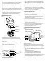
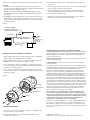
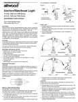
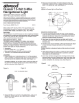
1
DO NOT use pump to remove gasoline, oil or other flammable liquids.
Doing so could result in fire, explosion, and serious personal injury.
3
®
Always use the fuse amperage rating specified for your pump model.
Failure to do so could result in serious personal injury or fire hazards.
Heavy Duty Bilge Pump
4030, 4060, 4031, 4061
Installation Instructions
Attwood marine hardware, navigational lighting, bilge pumps, and other
marine accessories are specified more than any other brand by America’s
best-known boat manufacturers as original equipment. Look to Attwood for
quality replacement parts and marine accessories.
SAVE THESE INSTRUCTIONS
Form Number 69317 Rev. D
03/10
FEATURES
Attwood Heavy Duty Bilge Pumps are the newest development in high output
pumps. All models have a removable housing for simple installation and easy
cleaning. They connect to 12-volt D.C. systems only. There are two ways to
configure your Heavy Duty Bilge Pump – Automatic Operation or Manual
Operation. The bilge pump system can be converted to fully-automatic
operation by installing the Attwood Automatic Float Switch, Part No. 4201
or 4202.
Attwood bilge pumps are designed to exhaust standing WATER ONLY.
They are not intended to prevent rapid accumulation of on-board water
due to rough weather, severe storms, hull damage, and/or other unsafe
navigational conditions.
Do not allow materials containing acetic acid (vinegar smell) such as
silicone rubber sealant to contact the plastic parts of the pump. They
may react with the plastic, causing cracks and pump failure.
Notice:
Discharge of oil prohibited. The Federal Water Pollution Control Act
prohibits the discharge of oil or oily waste into the contiguous zone.
Violators are subject to a penalty of $5,000.
REQUIRED FOR INSTALLATION
•
Drill and suitable drill bits
•
Screwdriver and four #8 stainless steel pan head screws
•
Attwood thru-hull connector of appropriate size (if not already installed
on boat; see chart)
•
Marine sealant
•
1-1/8" (29mm) inside diameter smooth-bore hose of suitable length
•
Two appropriate hose clamps
AUTOMATIC OPERATION
All boats over 20' (6.1 m) in length which have sleeping accommodations
(excluding fold-out cockpit seats) require automatic bilge pump systems. For
fully-automatic operation, follow the AUTOMATIC FLOAT SWITCH INSTALLATION and AUTOMATIC OPERATION WIRING instructions.
•
16-gauge wire, brown
•
16-gauge wire, black
•
Attwood 2-Way Dash-Mounted Control Switch (Part No. 7615), 3-Way
Switch (Part No. 7615A)
MANUAL OPERATION
For manual operation of your bilge pump system, disregard the references to
Automatic Float Switch installation and operation.
•
Fuse holder and appropriate fuse (see chart)
•
Two insulated terminal connectors for 16-gauge wire
•
Suitable materials to waterproof electrical connections
Check the chart below to select the proper pump, fuse size, and thru-hull
connector for your boat application:
Pump
Part
Number
Pump
Model
Volts
Amp
Fuse
Outlet Hose
Inside Dia.
4030, 4031
4060, 4061
HD1700
HD2000
12VDC
12VDC
10
12
1-1/8" (29mm)
1-1/8" (29mm)
•
Attwood Automatic Float Switch, Part No. 4201 (with cover) or
4202 (without cover)
Thru-Hull
Connector
•
Shim for float switch mounting
3874
3874
•
Three additional #8 round-head stainless steel attaching screws
The following materials are needed if no pump mounting pad is in place:
Recommendations are based on amount of gallons exhausted per hour
(GPH). GPH measurements are typical of production pumps tested using
smooth-bore hoses, at 0' head. “Head” refers to the vertical distance between
the pump nozzle and the water discharge location. GPH is reduced as head is
increased.
The chart below shows gallons and liters per hour ratings for 0' head and 3'
(91.4 cm) head. GPH/LPH may also vary depending on power source, hose
type, and other variables.
ABYC Specifications
13.6 volts DC
(GPH=Gallons Per Hour)
Part
No.
Model
GPH
Open
Flow
4030, 4031
4060, 4061
HD1700
HD2000
1,700
2,000
If automatic operation is desired:
• 1/2" (1.27 cm) thick marine plywood block large enough to mount pump
(and automatic float switch, if used)
• Hand-held roller
• Fiberglass—18 oz. (.5kg) mat or woven roving
• Polyester resin and catalyst
MOUNTING PREPARATION
Figure 1
ISO Specifications
12.0 volts DC
(LPH=Liters Per Hour)
Thru-Hull Connector
•
•
LPH
Open
Flow
GPH
3'
Head
LPH
3'
Head
Amp
Draw
6,450
7,600
1,300
1,550
4,920
5,867
6.0
8.0
Hose Clamp
Hose
The pumps can run dry for limited periods of time; however, doing so could
cause pump failure.
WARNING:
To prevent personal injury, always disconnect the power source when
installing or servicing any electrical product. Remove vessel from water
when using any 110/120 or 220 Volt AC power tools.
•
•
•
Water
Line
•
Hull
•
1/2" (Minimum) Thick Mounting Pad
1. Choose a bilge pump mounting location in the lowest accessible part of the
bilge. In this location, pump will remove the last 1" (2.54 cm) of standing
water. Also, pump should be as close to the thru-hull connector as
possible, for short discharge hose length.
1. Select a location on the pump mounting pad forward of the bilge pump.
NOTE: It is important to locate the switch forward of the pump to minimize
the possibility of running the pump when there is not enough standing
water, causing the pump to draw air and not turn off.
2. To install mounting pad on fiberglass hull:
Sand gelcoat or paint off the mounting surface to create an area that is 3"
(7.6cm) wider than the mounting pad on each side.
2. Attach shim to mounting pad with a layer of polyester resin.
Completely cover the mounting pad with fiberglass. Saturate the fiberglass
with resin, and press the fiberglass edges down against the hull to adhere
the pad in place. Roll out the fiberglass to remove any uneven surfaces, air
bubbles, or excess resin.
To install mounting pad on aluminum hull:
If your boat is not equipped with a bilge pump mounting pad we recommend that you consult your boat dealer or repair facility for instructions
regarding fabrication and installation of a suitable mounting pad.
PUMP MOUNTING INSTRUCTIONS
3. After resin has dried, center automatic float switch on top of shim.
If you have an Attwood switch without a cover, thread two #8 screws
through attachment holes on switch. Fasten securely into mounting pad.
If you have an Attwood switch with a cover, thread three #8 screws through
cover, then switch. Fasten securely to mounting pad.
HOSE CONNECTION INSTRUCTIONS
1. If no thru-hull connector exists:
Install connector well above the water line (just under the rub rail is best) on
the driver side, where water discharge can be easily monitored. Drill a hole
through the hull to clear the connector threads.
Apply marine sealant around inside of nut flange (do not allow sealant to
contact pump housing). Fully insert thru-hull connector, and screw nut
flange down firmly. Do not over tighten.
Figure 2
LOCK
2. Run hose from pump nozzle up to thru-hull connector, through the most
direct and unobstructed path possible.
3. Before connecting hoses, cut any extra length from hose that causes
downward dips or kinks in discharge line (dips can trap water and airlock
the pump). Be sure the hose tension on the pump outlet is minimized to
reduce stress on the pump components.
4. Place hose clamps onto hose ends. Connect ends to pump nozzle and
thru-hull connector, ensuring that hose ends fit tightly over barbs.
5. Secure both connections with hose clamps.
•
Locking Button
WIRING INSTRUCTIONS FOR AUTOMATIC OPERATION
Figure 4
•
Mounting Screws
•
Retaining Tabs
3-Way Switch On/Auto/Manual
HD 1700: 10 Amp Rating
HD 2000: 12 Amp Rating
HD 1700: 10 Amp Fuse
HD 2000: 12 Amp Fuse
Manual
••
Auto
• • •
Off
•
•
•
•
Brown Wire
•
72" (183mm)
Maximum
Length From (+)
Terminal To
Fuse Holder
•
1. Determine which direction you want pump outlet fitting to point after
installation. Mark pump base and mounting pad in desired position. If
Automatic Float Switch is to be installed, allow enough room on pad for
shim and switch.
2. Remove pump base from motor housing by depressing lock button and
twisting clockwise.
3. Align base with pad at marks, and fasten with four #8 screws.
4. Attach pump to base by aligning four retaining tabs and twisting counterclockwise until the lock button snaps into place.
AUTOMATIC FLOAT SWITCH INSTALLATION
–
+
•
Automatic Float Switch
•
12 Volt Battery
Black Wire
NOTE: The selected float switch must have an amp rating equal to or greater
than the recommended fuse.
Make all wire connections above the highest possible water level, using
marine grade wire connectors only. Waterproof all connections with suitable
materials. NOTE: Failure to make waterproof connections and fuse pump
properly will void the product warranty.
1. Splice suitable lengths of brown and black 16-gauge wire to existing pump
wiring, enough to reach ON/OFF/AUTO switch, automatic float switch, and
battery.
Figure 3
2. Using insulated terminal connectors:
Automatic Float Switch
Connect positive lead (brown) to the ON/OFF/AUTO switch.
Test Knob
Connect negative lead (black) to negative (-) battery terminal.
•
•
•
•
Bilge Pump
•
Shim
Float Switch Must Shut Pump Off Before
the Pump Cavitates (Draws Air and Stops Pumping)
In a location easily accessible for changing fuses, splice fuse holder into
positive lead (brown). The fuse holder must be installed within 72" (183 cm)
of the positive (+) battery terminal. Connect remaining lead from fuse
holder to positive (+) terminal of the three-way switch.
3. Splice the remaining positive lead (brown) from the automatic float switch
into the positive lead (brown) from the pump.
4. Connect the spliced leads to the ”Manual” terminal of the three-way switch.
®
Important:
Although the switch is submersible, the lead wires must terminate in a
waterproof connection. Mount wires above the highest possible water mark
to prevent electrolysis damage to the boat.
3
Heavy Duty Bilge Pump
5. With three-way switch on AUTO, test float switch by gently raising the
float.
Pump
should activate
float up, and deactivate with float down.
4030,
4060,
4031,with
4061
See figure 4
Installation Instructions
6. Test pump by ensuring that pump turns on when water level is above float
Attwood
marine
navigational
pumps,
and other
switch,
and
shutshardware,
off when water
level is lighting,
pumpedbilge
below
float switch.
Cycle
marine
arethe
specified
more than
other brand
by system
America’s
the
pumpaccessories
with water in
bilge several
timesany
to ensure
that the
is
best-knownproperly.
boat manufacturers as original equipment. Look to Attwood for
functioning
quality replacement parts and marine accessories.
Figure 5
3. Inspect impeller chamber and motor shaft behind impeller. Remove any
foreign objects.
4. Inspect “O” ring on lower chamber for nicks, cuts or other damage. Apply a
light coat of petroleum jelly to “O” ring surface.
5. Assemble chamber into motor housing. Ensure “O” ring is in retaining
groove and alignment pin is in pin receptacle next to locking button.
6. Install and tighten retaining screws.
7. Attach motor housing to pump base by aligning four retaining tabs and
twisting clockwise until lock button snaps into place.
SAVE THESE INSTRUCTIONS
Form
69317 Rev. D
2-WayNumber
Switch On/Off
HD 1700: 10 Amp Rating
HD 2000: 12 Amp Rating
On
•
••
• • Off
•
•
Brown Wire
03/10
72" (183mm)
Maximum
Length From (+)
Terminal To
Fuse Holder
• HD 1700: 10 Amp Fuse
HD 2000: 12 Amp Fuse
•
•
+
–
Black Wire
12 Volt Battery
WIRING INSTRUCTIONS FOR MANUAL OPERATION
1. Splice suitable lengths of brown and black 16-gauge wire to existing pump
wiring, enough to reach ON/OFF/ switch and battery.
2. Using insulated terminal connectors, connect positive lead (brown) to the
ON/OFF switch. Connect negative lead (black) to ground.
3. In a location easily accessible for changing fuses, splice fuse holder into
positive lead (brown). The fuse holder must be installed within 72" (183 cm)
of the positive (+) battery terminal.
4. To check system, feed water into the pump. If flow appears to be too low,
make sure wires have been connected properly: brown-to-positive (switch),
and black-to-negative.
Figure 6
L
O
C
K
Impeller
•
•
Motor Housing
•
Locking Button
•
•
O-Ring
Pump Chamber
CLEANING INSTRUCTIONS
ATTWOOD HEAVY DUTY BILGE PUMP LIMITED WARRANTY:
ATTWOOD CORPORATION, 1016 North Monroe, Lowell, Michigan 49331,
(‘Attwood’) warrants to the original consumer purchaser that this Attwood
Bilge Pump will be free from defects in materials and workmanship under
normal use and service for:
Recreational/Pleasure Boats — A period of three (3) years from the date of
original consumer purchase.
Commercial Boats — A period of one (1) year from the date of original
consumer purchase.
This warranty does not extend to any batteries or fuses used with the pump.
This limited warranty is not applicable if the bilge pump has been damaged
by accident, improper installation, unreasonable use, lack of proper
maintenance, unauthorized repairs or modifications, or other causes not
arising out of defects in materials or workmanship. Attwood’s obligations
under this warranty are limited to repair of the product at Attwood’s plant or
replacement of the product at Attwood’s option and at Attwood’s expense.
Any expenses involved in the removal, reinstallation, or transportation of the
product are not covered by this warranty. The product must be returned to
Attwood’s plant at the address indicated above postage prepaid, with proof
of original purchase including date. If Attwood is unable to replace the bilge
pump and repair is not commercially practicable or cannot be timely made, or
if the original consumer purchaser is willing to accept a refund in lieu of repair
or replacement, Attwood may refund the purchase price, less an amount for
depreciation. The acceptance by Attwood of any product returned or any
refund provided by Attwood shall not be deemed an admission that the
product is defective or in violation of any warranty.
THIS WARRANTY IS ATTWOOD’S ONLY EXPRESS WARRANTY OF
THIS PRODUCT. NO IMPLIED WARRANTY SHALL EXTEND BEYOND
ONE (1) YEAR FROM THE DATE OF ORIGINAL CONSUMER PURCHASE.
ATTWOOD SHALL NOT BE LIABLE FOR ANY DAMAGES FOR LOSS OF
USE OF THIS PRODUCT, NOR FOR ANY OTHER INCIDENTAL OR
CONSEQUENTIAL DAMAGES, COSTS OR EXPENSES.
Some states do not allow limitations on how long an implied warranty lasts or
the exclusion or limitation of incidental or consequential damages, so the
above limitations and exclusions may not apply to you. This warranty gives
you specific legal rights and you may have other rights which may vary from
state to state.
1. To remove the motor housing from base: Depress the locking button and
twist motor housing counter-clockwise.
2. Remove three retaining screws that attach pump chamber to motor
housing. Remove chamber.
© 2003 Attwood Corporation
1016 N. Monroe Street, Lowell, MI 49331-0260 www.attwoodmarine.com