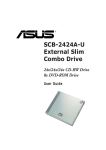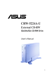
1
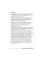
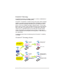
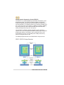
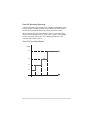
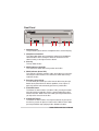
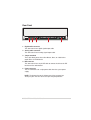
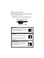
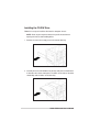
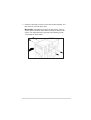
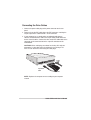
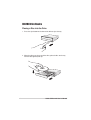
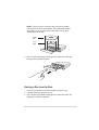
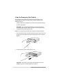
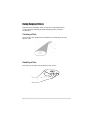
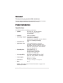
Welcome!
Thank you for buying the ASUS CRW-3212A Drive!
To ensure proper installation and use of this device, read the instructions
and other important information contained in this manual.
Product Introduction
Specifications
The CRW-3212A has the following specifications.
•
•
•
•
•
•
•
•
•
•
Speeds
32X, 24X, 16X, 12X, 8X, 4X writes
12X, 10X, 8X, 4X, 2X rewrites
16X~40X reads
Interface
ATAPI specification
Technology support FlextraSpeed™ Technology
FlextraLink™ Technology
Double Dynamic Suspension System II (DDSS II)
Zone CLV Recording Technology
Data buffer size
2MB
Application discs
12cm or 8cm diameter, 1.2mm thick
CD-Audio, CD-ROM, CD-ROM/XA, CD-I,
Mixed Mode CD-ROM, Photo CD, CD-Extra,
Video CD, CD-Text, DVCD, CD-G, Karaoke
CD, I-trax, Bootable CD
Recording form
Orange Book Part 2, 3
Disc-at-once, Track-at-once
Session-at-once, Packet write,
Overburn, DAO-RAW mode
OS compatibility
MS-Windows 98/98SE/ME/2000/XP/NT
SCO Unix, Linux, Netware, OS/2 Warp
Power supply
DC 5 x (1 +/- 5%)V
DC 12 x (1 +/- 10%)V
Dimensions
41.5 (h) x 149.0 (w) x 197.5 (d) mm
Mass
997 g
NOTE: Refer to the section “Technical Information” on page 26 for
detailed specifications.
ASUS CRW-3212A User’s Manual
9
Features
The ASUS CRW-3212A is a CD-RW drive with 32X-write, 12X-rewrite, and
40X-read capabilities. The drive complies with the AT Attachment Packet
Interface (ATAPI) specification and comes equipped with the latest
innovative technologies in CD recording.
Highlighting the major characteristic of ASUS CD-RW drives, the
CRW-3212A strategically identifies the media quality at the beginning of
the recording so that it can apply the appropriate writing speeds and
ensure effective data storage. Thanks to the FlextraSpeed™ and
FlextraLink™ technologies developed by ASUS.
FlextraSpeed™ increases accuracy and reliability when rewriting across a
broad base of certified media, while FlextraLink™ prevents buffer
underrrun problems to eliminate the creation of unusable discs. The
following sub-sections describe these technologies in detail.
FlextraSpeed™ Technology
The ASUS FlextraSpeed™ technology provides the optimum solution to
ensure quality recording when using discs that require flexible speeds. The
CRW-3212A drive employs this technology that allows automatic recording
speed adjustment based on the recording media.
In addition to the fact that there are low and high quality recording media,
various other factors such as dye layer, temperature, humidity, dust,
fingerprints, etc., affect the recording characteristics of CD-R and CD-RW
discs. Due to these factors, some discs may not be able to stand the highspeed capabilities of the latest CD-RW drives. The FlextraSpeed™
technology solves this problem by automatic assessment of the disc
quality and recording capability. The recording speed is based on these
factors. If you use a high quality recording disc, you can maximize the
recording capability of the drive and get the best quality output. If you use
a low quality disc, the drive speed adjusts to the level that is most
appropriate for the disc, still optimizing the disc recording capability.
The FlextraSpeed™ technology also helps maintain the CD-RW drive
because of the controlled motor rotation speeds and reduced noise
caused by spindle air, thus prolonging the drive motor’s life and ensuring
high-quality recording.
10
ASUS CRW-3212A User’s Manual
FlextraLink™ Technology
The ASUS FlextraLink™ technology provides a seamless combination of
flexibility and ultra-reliable recording quality.
FlextraLink™ incorporates a flexible strategy that prevents buffer underrun
problems caused by an empty data buffer. This CD-RW drive technology
allows continuous monitoring of the data buffer status during the write
process. Once the available data drops to approximately 1% of the total
buffer capacity, the drive stops recording and marks the last write position.
When new data is received from the host, it is loaded to the data buffer,
and the laser is repositioned to link the new data with the data already
written. FlextraLink™ uses minimal system resources so that your PC
remains fully operational throughout the writing process, and available for
other applications.
The diagram below shows the advantage of the FlextraLink™ recording
technology.
FlextraLink™ Technology Solution
Data
Data
Data transfer
slows down
Conventional
Recording
Buffer
Memory
Data transfer slower
than write process
Buffer
Memory
Empty
Write Data
Write process
continues
Data
Write Data
Bad disc results
Buffer
Memory
Data
Data
Data transfer
slows down
Data transfer continues
and fills buffer with
sufficient data for writing
Buffer
Memory
Recording with
FlextraLink™
Technology
Buffer
Memory
Write Data
Write Data
Write process stops;
waits until there is
enough data for writing
ASUS CRW-3212A User’s Manual
Write process continues
until writing is complete
11
Double Dynamic Suspension System (DDSS II)
The DDSS II is an enhanced follow up to the DDSS anti-vibration system
developed by ASUS. The DDSS CD-ROM technology is designed to
reduce the vibration generated from spindle rotation of over 8900 rpm of
40X CD-ROM drives. The DDSS II improves this feature by handling up to
over 10,000 rpm of the new 50X drives. In addition, the DDSS II stabilizes
the pick-up head of the drive in both horizontal and vertical directions,
making tracking and focusing even more precise.
Like the DDSS, the DDSS II vibration absoption structure contains a
“dynamic mass” that can absorb the vibration caused by high revolution of
spindle motor. However, the DDSS II moves the dynamic mass to be
suspended to the chassis, thus providing more stability and accuracy
when accessing data from the disc.
The following diagram illustrates the DDSS/DDSS II design structure.
DDSS / DDSS II Design Structure
12
ASUS CRW-3212A User’s Manual
Zone CLV Recording Technology
The Zone Constant Linear Velocity (CLV) recording method allows you to
achieve a higher recording speed by using a different speed for each of
the four zones partitioned from the inner to the outer area in a disc.
When using the Zone CLV, the recording in Zone 1 is 16X speed, then
increases to 20X speed in Zone 2, after t1 time. In Zone 3, the recording
reaches 24X speed, after t2 time. The recording speed reaches the
maximum 32X in Zone 4, after t3.
Zone CLV Recording Method
Speed
32x
Zone4
24x
Zone3
20x
16x
Zone2
Zone1
t1
t2
ASUS CRW-3212A User’s Manual
t3
Time
13
Front Panel
¤
Recordable
Rewritable
1
2
3
High Speed
32x12x40x
R
W
4
5
6
7
8
1. Headphone jack
This jack allows you to connect a headphone with a stereo mini-plug.
2. Headphone volume dial
This volume dial allows you to control the volume of the headphone
connected to the drive. Turning the dial to the left decreases the
volume, turning to the right increases volume.
3. Disc tray
This tray holds the disc.
4. WRITE indicator (Red LED)
This LED flashes while data is being written on the disc.
5. READ indicator (Green LED)
This LED turns ON when you place a disc on the drive tray, and stays
ON until you remove the disc. The LED flashes while data is being
read from the disc.
6. Emergency eject pinhole
In cases when you cannot eject a disc from the drive using the eject
button due to power failure or software problems, insert a pin or a
paper clip into this hole to manually eject the tray and the disc.
7. PLAY/SKIP button
This button has two functions. If the drive is idle, pressing this button
will start playing an audio disc (if one is currenly loaded in the drive)
from the first track. While in the PLAY mode, pressing this button lets
you skip to the next track on the disc.
8. STOP/EJECT button
This button has two functions. Pressing this button at any time ejects
the disc tray so you can place or remove a disc. While in PLAY mode,
pressing this button stops playing the disc loaded in the drive.
14
ASUS CRW-3212A User’s Manual
Rear Panel
1
2
3
4
5
1. Digital audio connector
This connector is for a digital signal output cable.
2. Analog audio connector
This connector is for an analog signal output cable.
3. Jumper terminals
These pins allow you to select either Master, Slave, or Cable Select
mode for the CD-ROM device.
4. IDE connector
This connector is for a 40-pin IDE cable to connect the drive to the IDE
interface on the motherboard.
5. Power connector
This DC connector is for a 4-pin power cable from the system power
supply.
NOTE: The jumper pins on the leftmost part of the rear panel are
factory test pins. DO NOT cover these pins with jumper blocks.
ASUS CRW-3212A User’s Manual
15
Installation
System Requirements
Before installing and using the CD-RW drive, make sure that your
computer system meets the following requirements.
•
IBM-compatible Pentium 166MHz or higher PC
•
Windows 98/98SE/ME/2000/XP/NT 4.0, Linux, or OS/2 Warp operating
system
•
At least 64MB system memory (128MB is recommended)
•
An empty 5.25-inch external drive bay
•
HDD empty storage capacity of 100MB or more
Average seek time: 20ms or less
Transmission rate: 2 MB/s or more
NOTE: Do not use a hard disk that calibrates thermally during
operation.
•
Recommended media:
CD-R
Sony, TDK, Ricoh, Kodak, Mitsubishi
Chemical, Taiyo Yuden, Yamaha, Philips,
Ritek, Prodisc, AMT, Princo, Hitachi Maxwell,
CMC
CD-RW
16
Sony, TDK, Ricoh, Yamaha, Mitsubishi
Chemical, Ritek, Prodisc, AMT, CMC
ASUS CRW-3212A User’s Manual
Setting the Jumper Terminals
Configure the the jumpers to set the device to master or slave mode
before physically installing it to your computer chassis. Use jumper blocks
to short the pins to your desired setting.
CAUTION: Make sure to correctly place the jumper blocks over the
pins. Failure to do so may cause irreparable damage to the drive!
Jumper
Terminals
Master Mode
Cover the two pins labeled MASTER to set the CD-RW
drive as a secondary master drive. This is possible only if
your computer supports four IDE devices. The hard disk in
the computer is set as Primary Master.
Slave Mode
Cover the two pins labeled SLAVE to set the CD-RW drive
as a slave device if your computer supports only two IDE
devices.
If your computer supports four IDE devices, this setting
sets your CD-RW drive either as a Primary Slave or a
Secondary Slave.
Cable Select Mode
Cover the two pins labeled CABLE SELECT if your
computer supports a Cable Select (CSEL) signal. You
need an exclusive interface cable for this setting. Refer to
your computer manual for details.
ASUS CRW-3212A User’s Manual
17
Installing the CD-RW Drive
Follow these steps to install the drive into the computer chassis.
NOTE: Refer to your computer manual for specific instructions on
opening the chassis and installing drives.
1. Remove the cover of an empty 5.25-inch external drive bay.
2. Carefully insert the CD-RW drive into the bay and push it inward until it
is flushed to the chassis front panel. The holes on the sides of the drive
should align with the holes on the drive bay.
18
ASUS CRW-3212A User’s Manual
3. Secure the drive with screws that came with the drive package. Use
two screws on each side of the drive.
IMPORTANT: Depending on the space on your chassis, you may
need to connect the drive cables before securing the drive into the
chassis. For cable connections, proceed to the following section,
“Connecting the Drive Cables.”
ASUS CRW-3212A User’s Manual
19
Connecting the Drive Cables
1. Connect the power cable plug to the power connector on the rear
panel.
2. Connect the 40-pin IDE cable plug to the IDE connector, matching the
red pin stripe on the cable with Pin 1 on the connector.
3. If your computer has a sound card or an onboard audio feature,
connect an audio interface cable to the 4-pin analog audio connector
on the rear of the drive. Connect the other end of the audio cable to the
connector on the sound card or on the 4-pin CD connector on the
motherboard.
CAUTION! All the cable plugs are slotted so that they fit in only one
orientation. If a plug does not fit in completely, try reversing it. DO
NOT use too much force when fitting the cable plugs.
Power
Cable
4-pin Audio
Cable
IDE
Cable
NOTE: Replace the computer cover according to your computer
manual.
20
ASUS CRW-3212A User’s Manual
Installing the Device Driver
Before you can use your CRW-3212A drive, you must first install the
device driver.
IMPORTANT! Make sure you that you have completed the drive
installation and have replaced the computer cover before you
proceed.
Follow these steps to install the device driver.
1. Turn on the computer.
2. Your operating system (OS) detects the new hardware (CD-RW drive)
that you installed and automatically looks for the appropriate driver.
3. Follow the screen instructions to install the driver.
Installing the CD-RW Software
The ASUS CRW-3212A drive supports the following software applications.
By AHEAD software gmbh
•
•
•
•
Nero Burning ROM
In CD
Wave Editor
Cover Designer
By Microsoft Corporation
•
•
•
Media Player
CD Player
Active Movie
By Kodak
•
Kodak Photo CD Player, V2.0 or higher
By NewTech Infosystems, Inc.
•
•
•
•
•
•
CD-Maker
File CD
Overburn™ Support
Advanced Caching
Playlist (M3U File) Support
SVCD Support
NOTE: Refer to the manuals that came with the specific software
for installation instructions.
ASUS CRW-3212A User’s Manual
21
CD-RW Drive Basics
Placing a Disc into the Drive
1. Press the eject button on the front of the drive to eject the tray.
2. When the drive tray ejects out of the drive, place the disc on the tray
with the label (printed) side up.
22
ASUS CRW-3212A User’s Manual
NOTE: If you are using a 12-cm disc, place it on the tray making
sure that it fits the outer circular border. This border helps hold the
disc in place. If you are using an 8-cm disc, place it on the inner
circular border on the tray.
12-cm
Disc
8-cm
Disc
3. Press the drive eject button or lightly push the center of the drive tray
to replace the tray inside the drive.
Ejecting a Disc from the Drive
1. Press the eject button on the front of the drive to eject the tray.
2. Carefully remove the disc from the tray.
3. Press the drive eject button or lightly push the center of the drive tray
to load the tray back into the drive.
ASUS CRW-3212A User’s Manual
23
Using the Emergency Eject Pinhole
The emergency eject pinhole on the front of the drive allows you to
manually eject the drive tray and remove a disc from the drive in the
following instances:
•
•
supply of power to the computer is cut due to electrical power outage
the drive malfunctions
CAUTION! Use the manual method only as a last resort when the
eject button does not work. Make sure that you have turned off your
computer before ejecting the drive tray.
Follow these steps to eject the drive tray using the emergency pinhole.
1. Insert the eject pin that came with the drive package. You may also use
a paper clip or any pointed rod small enough to fit into the emergency
pinhole.
2. Carefully pull the tray out and remove the CD.
CAUTION! Do not force the tray open; wait until the eject pin has
dislodged the tray to avoid breaking the tray panel.
24
ASUS CRW-3212A User’s Manual
Using Compact Discs
Take note of the instructions in this section when using compact discs.
These instructions will help you avoid damaging the discs and your
CD-RW drive.
Cleaning a Disc
Spray the disc with compressed air for about five seconds to get rid of the
dust on a disc.
Handling a Disc
Hold a disc by the edges. Do not touch the disc surface.
ASUS CRW-3212A User’s Manual
25
Technical Information
Environmental Specifications
Temperature
Operation:
Storage:
5°C < to < 45°C
- 20°C to < 60°C
Humidity
Operation:
Storage:
20% to 80% non-condensing
15% to 85% non-condensing
Vibration
Operation:
Storage:
0.3G peak at 5 ~ 500 Hz
2.0G peak at 10 ~ 500 Hz
Impact
Non-operation:
1 oct/min – no damage
Less than 50G –
(at 11ms/half sine wave,
3 shock/each side)
1 oct/min – no damage
91 cm high –
(1 corner, 3 edges, 6 surfaces)
Packaged:
Acoustic
Access mode:
41.5 dB TYP
Read mode:
44.5 dB TYP
(Microphone located 50cm in front of the drive, 120cm above the drive at 30°
angle.)
Reliability
MTBF:
ODC (Read):
ODC (Write):
100,000 power on hours
20% of power on time
1% of power on time
Mean Time To Repair (MTTR)
30 minutes
* ODC - Operating Duty Cycle
Electrical and Audio Specifications
26
Power Source
Voltage
Tolerance
Ripple
Rating
+5V DC
+/- 5%
150m Vpp
900mA
+12V DC
+/- 10%
300m Vpp
1500mA
I/O Terminal
Power connector
ATAPI terminal
Audio out
4-pin +5V, +12V
40-pin
4-pin (analog)
2-pin (digital)
Audio
No. of channels
Sampling frequency
Quantization
Distortion
S/N ratio
Output: Headphone
Line Out
2 (stereo)
44.1 kHz
16 bits
0.2% max. (at 1 kHz)
70 dB
0.7 V rms (typical)
0.7 V rms (typical)
ASUS CRW-3212A User’s Manual