1
Digital Audio Products
SYSTEM II
Operating Manual
4.24G - Four Channel Graphic Equalizer/System Processor
4.24GS - Four Channel Graphic Equalizer/System Processor Slave
2.24GS - Two Channel Graphic Equalizer/System Processor Slave
4.24PS - Four Channel Parametric Equalizer/System Processor Slave
2.24PS - Two Channel Parametric Equalizer/System Processor Slave
4.24RD - Full Function Graphic Equalizer Remote Control
Protea System Software
ASHLY AUDIO INC.
847 Holt Road Webster, NY 14580-9103 Phone: (716) 872-0010
Toll-Free: (800) 828-6308 Fax: (716) 872-0739
www.ashly.com
Operating Manual - PROTEA SYSTEM II Digital Audio Products
Table Of Contents
2
1
INTRODUCTION . . . . . . . . . . . . . . . . . . . . . . . . . . . . . . . . . . . . . . . . . . . . . . . . .
1.1 Protea Products . . . . . . . . . . . . . . . . . . . . . . . . . . . . . . . . . . . . . . . . . . . . . . . . . .
1.2 Audio Features . . . . . . . . . . . . . . . . . . . . . . . . . . . . . . . . . . . . . . . . . . . . . . . . . .
1.3 User Interface . . . . . . . . . . . . . . . . . . . . . . . . . . . . . . . . . . . . . . . . . . . . . . . . . . .
1.4 Protea System Concepts . . . . . . . . . . . . . . . . . . . . . . . . . . . . . . . . . . . . . . . . . . .
4
4
5
5
5
2
AC POWER REQUIREMENTS . . . . . . . . . . . . . . . . . . . . . . . . . . . . . . . . . . . . . 6
3
UNPACKING . . . . . . . . . . . . . . . . . . . . . . . . . . . . . . . . . . . . . . . . . . . . . . . . . . . . . . 6
4
TYPICAL PROTEA APPLICATIONS . . . . . . . . . . . . . . . . . . . . . . . . . . . . . . .
4.1 Stand-Alone . . . . . . . . . . . . . . . . . . . . . . . . . . . . . . . . . . . . . . . . . . . . . . . . . . . . .
4.2 With 4.24RD Remote Control Unit . . . . . . . . . . . . . . . . . . . . . . . . . . . . . . . . . .
4.3 Multi-Channel Protea System . . . . . . . . . . . . . . . . . . . . . . . . . . . . . . . . . . . . . .
4.4 Computer Control with Protea System Software . . . . . . . . . . . . . . . . . . . . . . .
4.5 With Third-Party MIDI System . . . . . . . . . . . . . . . . . . . . . . . . . . . . . . . . . . . . .
5
KEYBOARD CONTROL FEATURES . . . . . . . . . . . . . . . . . . . . . . . . . . . . . . . 7
5.1 Bank . . . . . . . . . . . . . . . . . . . . . . . . . . . . . . . . . . . . . . . . . . . . . . . . . . . . . . . . . . . 7
5.2 Channel . . . . . . . . . . . . . . . . . . . . . . . . . . . . . . . . . . . . . . . . . . . . . . . . . . . . . . . . 7
5.3 Menu Keys . . . . . . . . . . . . . . . . . . . . . . . . . . . . . . . . . . . . . . . . . . . . . . . . . . . . . . 8
5.4 On-Line Help . . . . . . . . . . . . . . . . . . . . . . . . . . . . . . . . . . . . . . . . . . . . . . . . . . 11
5.5 Esc . . . . . . . . . . . . . . . . . . . . . . . . . . . . . . . . . . . . . . . . . . . . . . . . . . . . . . . . . . . 11
5.6 Recall . . . . . . . . . . . . . . . . . . . . . . . . . . . . . . . . . . . . . . . . . . . . . . . . . . . . . . . . . 11
5.7 Save . . . . . . . . . . . . . . . . . . . . . . . . . . . . . . . . . . . . . . . . . . . . . . . . . . . . . . . . . . 12
5.8 Flat . . . . . . . . . . . . . . . . . . . . . . . . . . . . . . . . . . . . . . . . . . . . . . . . . . . . . . . . . . . 12
5.9 Copy . . . . . . . . . . . . . . . . . . . . . . . . . . . . . . . . . . . . . . . . . . . . . . . . . . . . . . . . . . 12
5.10 In/Out . . . . . . . . . . . . . . . . . . . . . . . . . . . . . . . . . . . . . . . . . . . . . . . . . . . . . . . . 12
5.11 Mute . . . . . . . . . . . . . . . . . . . . . . . . . . . . . . . . . . . . . . . . . . . . . . . . . . . . . . . . . 13
5.12 Scene . . . . . . . . . . . . . . . . . . . . . . . . . . . . . . . . . . . . . . . . . . . . . . . . . . . . . . . . 13
5.13 CapsLock . . . . . . . . . . . . . . . . . . . . . . . . . . . . . . . . . . . . . . . . . . . . . . . . . . . . . 13
5.14 Gain . . . . . . . . . . . . . . . . . . . . . . . . . . . . . . . . . . . . . . . . . . . . . . . . . . . . . . . . . 13
5.15 Factory Reset . . . . . . . . . . . . . . . . . . . . . . . . . . . . . . . . . . . . . . . . . . . . . . . . . . 13
6
INTERCONNECT FEATURES . . . . . . . . . . . . . . . . . . . . . . . . . . . . . . . . . . . . .
6.1 Audio . . . . . . . . . . . . . . . . . . . . . . . . . . . . . . . . . . . . . . . . . . . . . . . . . . . . . . . . .
6.2 MIDI . . . . . . . . . . . . . . . . . . . . . . . . . . . . . . . . . . . . . . . . . . . . . . . . . . . . . . . . .
6.3 RS-232 . . . . . . . . . . . . . . . . . . . . . . . . . . . . . . . . . . . . . . . . . . . . . . . . . . . . . . . .
6.4 Contact Closures . . . . . . . . . . . . . . . . . . . . . . . . . . . . . . . . . . . . . . . . . . . . . . . .
6
6
6
6
7
7
13
13
14
14
14
Operating Manual - PROTEA SYSTEM II Digital Audio Products
7
MIDI IMPLEMENTATION . . . . . . . . . . . . . . . . . . . . . . . . . . . . . . . . . . . . . . . .
7.1 MIDI and the Four Banks. . . . . . . . . . . . . . . . . . . . . . . . . . . . . . . . . . . . . . . . .
7.2 Selecting the MIDI Channels . . . . . . . . . . . . . . . . . . . . . . . . . . . . . . . . . . . . . .
7.3 Continuous Controller Reference Table . . . . . . . . . . . . . . . . . . . . . . . . . . . . .
15
15
15
16
8
PROTEA 4.24RD REMOTE CONTROL . . . . . . . . . . . . . . . . . . . . . . . . . . . . 16
9
PROTEA SLAVE UNITS . . . . . . . . . . . . . . . . . . . . . . . . . . . . . . . . . . . . . . . . . . 17
10 PROTEA SYSTEM SOFTWARE . . . . . . . . . . . . . . . . . . . . . . . . . . . . . . . . . . .
10.1 How to Get Protea System Software . . . . . . . . . . . . . . . . . . . . . . . . . . . . . . .
10.2 Installing Protea System Software. . . . . . . . . . . . . . . . . . . . . . . . . . . . . . . . .
10.3 Connecting To A Computer . . . . . . . . . . . . . . . . . . . . . . . . . . . . . . . . . . . . . .
17
17
17
17
11 TROUBLESHOOTING . . . . . . . . . . . . . . . . . . . . . . . . . . . . . . . . . . . . . . . . . . . .
11.1 4.24G Main Troubleshooting Tips . . . . . . . . . . . . . . . . . . . . . . . . . . . . . . . . .
11.2 Slave Troubleshooting Tips . . . . . . . . . . . . . . . . . . . . . . . . . . . . . . . . . . . . . .
11.3 Battery Replacement . . . . . . . . . . . . . . . . . . . . . . . . . . . . . . . . . . . . . . . . . . . .
18
18
18
18
12 WARRANTY INFORMATION . . . . . . . . . . . . . . . . . . . . . . . . . . . . . . . . . . . . . 18
13 DIMENSIONS . . . . . . . . . . . . . . . . . . . . . . . . . . . . . . . . . . . . . . . . . . . . . . . . . . . . 19
14 SPECIFICATIONS . . . . . . . . . . . . . . . . . . . . . . . . . . . . . . . . . . . . . . . . . . . . . . . . 19
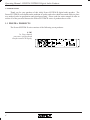
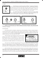
The lightning flash with arrowhead
symbol, within an equilateral triangle, is
intended to alert the user to the presence
of uninsulated "dangerous voltage" within
the product's enclosure that may be of
sufficient magnitude to constitute a risk
of electric shock to persons.
The exclamation point within an eqilateral
triangle is intended to alert the user to the
presence of important operating and
maintenance instructions in the literature
accompanying the device.
TO REDUCE THE RISK OF ELECTRIC SHOCK, DO NOT
REMOVE COVER. NO USER SERVICEABLE PARTS INSIDE.
REFER SERVICING TO QUALIFIED SERVICE PERSONNEL.
TO REDUCE THE RISK OF FIRE OR ELECTRICAL SHOCK,
DO NOT EXPOSE THIS APPKIANCE TO RAIN OR MOISTURE.
TO REDUCE THE RISK OF FIRE, REPLACE ONLY WITH
SAME TYPE FUSE. REFER REPL ACEMENT TO
QUALIFIED SERVICE PERSONNEL.
WARNING:
THIS APPARATUS MUST BE EARTHED
3
Operating Manual - PROTEA SYSTEM II Digital Audio Products
1. INTRODUCTION
Thank you for your purchase of this Ashly Protea SYSTEM II digital audio product. The
Protea SYSTEM II series builds on the tradition of quality and value which has earned Ashly its place
as a market leader in equalization and signal processing. Please read the entire manual in order to
realize all of the powerful features the Protea SYSTEM II series of products has to offer.
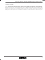
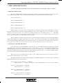
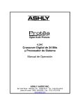
1.1 PROTEA PRODUCTS
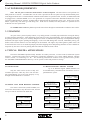
The Protea SYSTEM II series consists of the following seven products:
4.24G
2u, Four channel
processor with keyboard
interface and LCD display
Inputs
O utputs
P US H
Data In
Through
Data Out
PU SH
Data
Config
3
2
1
2
1
2
1
4
3
4
3
Ashly Audio Inc.
Made In USA
Model 4.24G
MIDI or RS -232 Slave
RS-232 Master Only
Ashly 4.24RD Remote or Other Midi Device
On
Digi tal Audio Pr oducts
(+) (-)
Off
Inputs are 18KΩ active balanced. Outputs may be wi red balanced or unbalanced.
4
Max imum in/out l evel i s +20 dBu.
Power
RS-232
115V or 230V
50-60H z 30W
AVIS: RI SQUE DE CHO C ELECTR IQUE NE PAS OUVRIR.
Operating Manual - PROTEA SYSTEM II Digital Audio Products
1.2 AUDIO FEATURES
The Protea audio components consist of state of the art technologies, beginning with a 24 bit, 48kHz deltasigma A/D converter with 128x oversampling. Digital processing includes EQ, Compression, Limiting, Shelving,
Highpass and Lowpass Filters, and Time Delay, taking place in a 100MHz Motorola DSP56303 high performance DSP
processor. D/A conversion uses a 24 bit delta-sigma converter with 128x oversampling. Inputs are precision balanced
and RF protected, while outputs may be wired balanced or unbalanced. All audio connections use XLR and 1/4" phone
5
Operating Manual - PROTEA SYSTEM II Digital Audio Products
2. AC POWER REQUIREMENTS
Note: The AC power switch for model 4.24G is on the back panel. All Protea devices will perform normally from 90 to 125VAC. A standard IEC-320 AC inlet is provided on the rear panel to accept the detachable power
cord shipped with the unit. Units distributed within the United States are preselected for 115VAC, 50-60Hz and should
be plugged into a standard NEMA 5-15 3-wire grounded AC receptacle. Most units distributed outside the US are
preselected and labeled for 230VAC, 50-60Hz and are shipped with the appropriate power cord. In the event of fuse
failure, replace only with same type and rating fuse. If the fuse is internal, refer the product to a qualified service
technician for fuse replacement.
The 4.24RD remote control is phantom powered from its host through two standard three-conductor XLR cables.
3. UNPACKING
As a part of our system of quality control, every Ashly product is carefully inspected before leaving the factory
to ensure flawless appearance. After unpacking, please inspect for any physical damage. Save the shipping carton and
all packing materials, as they were carefully designed to reduce to minimum the possibility of transportation damage
should the unit again require packing and shipping. In the event that damage has occurred, immediately notify your
dealer so that a written claim to cover the damages can be initiated. The right to any claim against a public carrier can
be forfeited if the carrier is not notified promptly and if the shipping carton and packing materials are not available for
inspection by the carrier. Save all packing materials until the claim has been settled.
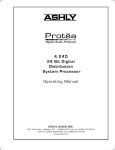
4. TYPICAL PROTEA APPLICATIONS
The Protea SYSTEM II product family includes five audio processors, a remote control, and Protea System
Software. Various Protea units can be combined to expand the capabilities of a system, adding channels, utilizing
remote control, or connecting to a PC. The following illustrations indicate some typical Protea systems.
See SYSTEM CONFIGURATION chart on p. 20 for specific switch and preference settings.
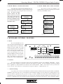
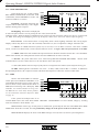
4.1 STAND-ALONE
Only the 4.24G can be used as a fully selfcontained processor, while any slave unit can function independently once it has been properly set up
through external hardware or software.
4.3 MULTI-CHANNEL PROTEA SYSTEM
Up to 16 different logical (MIDI) channels can
be simultaneously controlled from one Master in an expanded Protea system.
4.24RD Remote
XLR Data Out
XLR Data In
XLR Data In
4.2 SINGLE UNIT WITH REMOTE CONTROL
4.24G Main
Main Or Slave
(Data Config Switch Out)
Select MASTER in UserPrefs
*4.24G Main - Data Config Switch Out
Slaves - Switch A Out, Switch B Out
XLR Data Out
The remote control unit (model 4.24RD) connects to the main 4.24G or any other slave unit, and can
run up to 1000 ft. from the host audio unit.
4.24RD Remote
XLR Data In
XLR Data In
XLR Data Out
XLR Data In
Main Or Slave
Main Or Slave
*4.24G Main - Data Config Switch Out
Slaves - Switch A Out, Switch B Out
*4.24G Main - Data Config Switch Out
Slaves - Switch A Out, Switch B Out
XLR Data Out
XLR Data Out
XLR Data In
XLR Data In
Main Or Slave
Main Or Slave
*4.24G Main - Data Config Switch Out
Slaves - Switch A Out, Switch B Out
*4.24G Main - Data Config Switch Out
Slaves - Switch A Out, Switch B Out
XLR Data Out
XLR Data In
XLR Data Out
XLR Data Out
XLR Data In
XLR Data Out
XLR Data In
XLR Data In
Main Or Slave
Main Or Slave
Main Or Slave
*4.24G Main - Data Config Switch Out
Slaves - Switch A Out, Switch B Out
*4.24G Main - Data Config Switch Out
Slaves - Switch A Out, Switch B Out
*4.24G Main - Data Config Switch Out
Slaves - Switch A Out, Switch B Out
XLR Data Out
XLR Data Out
*4.24G Main - UserPrefs LCD Menu Must Select MIDI
6
Operating Manual - PROTEA SYSTEM II Digital Audio Products
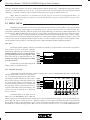
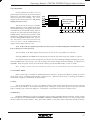
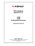
4.4 WITH PROTEA SYSTEM SOFTWARE
4.5 WITH THIRD PARTY MIDI SYSTEMS
Ashly PROTEA SYSTEM SOFTWARE adds flexibility by allowing comprehensive system control of main
or slave units from a PC using the RS-232 Serial port.
Note: the Data Config
Switch (Switch "B" On
Slaves) must be pressed
Protea System
"IN" only on the unit conSoftware
nected directly to the PC,
RS-232
and only if additional units
are connected through the
Main Or Slave
XLR Data cables.
*4.24G Main - Data Config Switch In
The Protea system uses MIDI as its
communication protocol, allowing for external
control by other MIDI sources.
MIDI In
Main Or Slave
*4.24G Main - Data Config Switch Out
Slaves - Switch A Out, Switch B Out
MIDI THRU
Slaves - Switch A In, Switch B In
XLR Data Out
XLR Data In
MIDI In
XLR Data In
Protea System
Software
RS-232
Third-Party
MIDI Master
MIDI
OUT
Main Or Slave
Main Or Slave
*4.24G Main - Data Config Switch Out
Slaves - Switch A In, Switch B Out
*4.24G Main - Data Config Switch Out
Slaves - Switch A Out, Switch B Out
MIDI THRU
XLR Data Out
MIDI In
XLR Data In
One Main Or Slave
Main Or Slave
Main Or Slave
*4.24G Main - Data Config Switch In
Slaves - Switch A In, Switch B Out
*4.24G Main - Data Config Switch Out
Slaves - Switch A In, Switch B Out
*4.24G Main - Data Config Switch Out
Slaves - Switch A Out, Switch B Out
XLR Data Out
*4.24G Main - UserPrefs LCD Menu Must Select RS232
*4.24G Main - UserPrefs LCD Menu Must Select MIDI
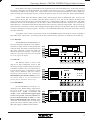
5. KEYBOARD CONTROL FEATURES
5.1 Bank
The four BANK keys are
only used on the MASTER Protea unit
when multiple units are chained together in a system. Note: The 4.24G
is shipped from the factory in SLAVE
mode, which disables the Bank keys,
but can be changed to Master status
in the UserPrefs Menu section, enabling the Bank keys and corresponding LED indicators. Once this is
done, each Bank key along with a
Channel key selects a MIDI channel.
Bank
A
Channel
Mute Sig
1
Preset
Menu
B
Four-Channel 24 Bit
Digital Graphic Equalizer/
System Processor
C
2
D
4
31
A
1
40
B
EQ
IN
Cmp/Lim OUT
HPF/LPF OUT
DELAY OUT
3
2
50
C
3
63
D
01
More
4
80
E
5
100
F
6
125
G
7
8
160
H
9
200
I
250
J
0
(space)
315
K
400
L
#
500
M
5.2 Channel
The four Channel keys determine which LOCAL CHANNEL becomes the CURRENT CHANNEL. A green
LED shows which Channel is currently selected to the display for editing. All four Channels will always remain
active, regardless of which Channel is selected as the Current Channel. Note: On the Master unit of a multi-unit
system, the four local channels are automatically assigned to Bank A, or MIDI channels 1-4.
* * * Channel Linking
If you desire one or more Local Channels to track the Current Channel, the Protea system allows CHANNEL
LINKING. This forces one, two, or even all three Local Channels' settings to become identical to and dependent on the
Current Channel, regardless of their previous settings. To link a channel, first select the Current Channel key and
simultaneously press and hold the channel key you wish to link, repeating if multiple channels are being linked. Once
the link is established, the lowest numbered Local Channel that is linked will become the current, dominant channel,
7
Operating Manual - PROTEA SYSTEM II Digital Audio Products
while any dependent channels will show a flashing LED to indicate linked status. Although the audio paths remain
separate, the linked channels now act as one. Any action taken on the Current Channel will also affect the Linked
Channel(s). To unlink a channel, simply repeat the linking process to toggle the linked channel off.
Note: When two channel keys are simultaneously pressed, a pop-up screen will say "Changing Link Status". In
order to prevent accidental linking, the channel keys must be held down for a couple seconds until this screen goes away
for the change to take effect.
5.3 MENU KEYS
The MENU keys allow quick access to the powerful audio and setup features of Protea products. There are four Menu
softkeys and a MORE key which toggles to a second Menu screen. The first screen shows the core audio functions, EQ,
Comp/Limiter, HPF/LPF, and Delay, while the second screen displays Metering, User Preferences, MIDI Implementation, and
Security features. When the Menu keys select a function, softkeys below the LCD adjust specific parameters within each menu.
An important point to mention regarding the two different Menu Screens is that the first screen consists of audio
controls which can be saved to individual Presets, and will vary as the Current Channel or recalled Preset changes. The second
screen involves system setup details which are global in nature, in other words they will remain constant regardless of the
Current Channel or Preset selection. The following sections explain each Menu and their adjustable parameters.
5.3.1 EQ
The Protea graphic equalizer consists of 28 bands of Constant Q, reciprocal filters on third octave frequencies
with up/down keys for each band. Multiple
bands can be adjusted at the same time, and inPreset 01
dividual frequencies can be set flat quickly by Menu
pressing both up and down keys together. Max
EQ
IN
filter boost and cut is 15dB, and filter Q is 3.2.
Cmp/Lim OUT
To begin a new EQ curve with all faders at 0dB,
HPF/LPF OUT
press the FLAT key.
DELAY
The IN/OUT key to the right of the LCD
display enables or disables the EQ.
OUT
More
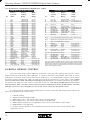
5.3.2 Cmp/Lim (Pre/Post)
A full featured, Pre/Post switchable compressor/limiter allows control of THRESHOLD, RATIO, ATTACK TIME,
and RELEASE TIME. Limiters are used primarily for eliminating large transient signals which
GAIN
OUT
Preset 01
THR RAT ATT REL
Thr
Pk
may damage speaker components, and are simi- Menu
0 4:1 5ms 100ms
-2
+12
-4
+9
larly used for keeping overall audio output levels
EQ
OUT
Pre -6
+6
-8
+3
Post
in a sound system within a specified range. All
Cmp/Lim IN
0
EQ -10
-12
-3
compressor/limiter parameters are adjusted with
HPF/LPF OUT
-15
-6
-18
-9
the appropriate softkey, found directly below its
DELAY OUT
-21
-12
respective slide-fader control on the display. The
More
current value for each parameter is displayed
630
800
1K
1.2K
1.6K
2K
2.5K
above its control.
Threshold (THR) is the signal level in
dBu or VU (see METERING) above which the
limiter begins to prevent further increases in audio levels. The available Threshold range is -20 to +20 when Meters are
set for dBu, and -24 to +16 when set for VU . Whenever signal level exceeds the Threshold, the limiter screen indicates
the resulting amount of Gain Reduction, or the amount of attenuation in dB which has occurred to signal above the
threshold level. Output Metering utilizes dBu or VU as selected in UserPrefs (see sec. 5.3.6 USER PREFERENCES).
8
Operating Manual - PROTEA SYSTEM II Digital Audio Products
Ratio (RAT) is the degree of attenuation to the signal above the limiter threshold point. As the ratio increases,
less signal is allowed to exceed the threshold. For example, with the ratio set at 10:1, a 10dB increase in input level
results in just a 1dB increase in output level. Thus a lower ratio is a more pleasant sounding effect, while a high ratio,
while accurately preventing signal increases, reduces the dynamic range to a point where the audio sounds unnatural.
Limiter Attack (ATT) and Release (REL) Time Controls display units in milliseconds (ms); however, the
actual units are ms per dB. For example, when the Release control is set at 100 ms, the limiter's attenuation will
release at the rate of 100 ms per dB, or viewed in another way, it would release 10dB over 1 second of time. The attack
and release time action was designed this way to achieve a more natural attack and release behavior of a constant rate
rather than time. It should be noted that fast attack and release times may distort the audio signal. This occurs in any
limiter because a fast attack or release action changes the gain rapidly which will by definition, distort the waveshape
of long wavelength (low frequency) signals. Therefore, it is recommended that longer attack and release times be used
for lower distortion.
10-segment meters on the LCD indicate amount of GAIN REDUCTION and OUTPUT LEVEL, including a
Peak LED on the output meter. As with EQ and all other audio functions, the limiter is enabled by the In/Out key.
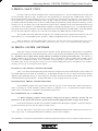
5.3.3 HPF/LPF
The HIGHPASS and LOWPASS filters offer precise frequency adjustment of two 24dB/octave filters, creating accurate visual representation
of the pass band. The frequency indicated for each
filter is the -3dB point. Use the four softkeys to
shift the frequency for each filter. To quickly shift
both filters "off" while in this menu, press the FLAT
key to the right of the display.
Preset 01
Menu
EQ
OUT
Cmp/Lim OUT
HPF/LPF IN
DELAY OUT
1K
10K 20K
LPF=10.0KHz
630
1.2K
1.6K
More
5.3.4 DELAY
The DELAY feature is used to time
align two or more loudspeaker sources so that
the acoustic energy created by different speakers
at different locations arrives simultaneously at
a given listening point. Adjustments are made
using Course, Medium, and Fine softkeys
displaying milliseconds, feet, and meters.
Maximum delay per channel is 1365ms. Quickly
reset Delay Time to zero by simultaneously
pressing the up and down "Course" keys.
20
100
HPF=99Hz
Preset 01
Menu
800
1K
Course
2.5K
DELAY TIME:
Medium
EQ
OUT
Cmp/Lim OUT
HPF/LPF IN
DELAY OUT
2K
0.00 ms
Fine
0.00 ft
0.00 m
More
630
800
1K
1.2K
1.6K
2K
2.5K
5.3.5 METERING
Press the MORE key to access the second menu screen. Meters display input and output levels in dBu or VU, selectable in the
UserPrefs menu. 0 dBu = 0.775Vrms, and
+4 dBu = 0 VU. To maintain the highest signal
to noise ratio possible, each local channel's input level should nominally be 0 dBu, or -4 VU,
allowing 20dB headroom before clipping. Each
of the four local channels also use a two-color
(green/red) LED to indicate signal present (-15
dBu) and clipping (+20dBu) for that channel.
Preset 01
(VU)
dB Meters
UserPrefs
MIDI
Security
Menu
1 PkIn Out 2 PkIn Out 3PkIn Out 4 PkIn Out
+12
+9
+6
+3
0
-3
-6
-9
-12
+12
+9
+6
+3
0
-3
-6
-9
-12
+12
+9
+6
+3
0
-3
-6
-9
-12
+12
+9
+6
+3
0
-3
-6
-9
-12
More
9
Operating Manual - PROTEA SYSTEM II Digital Audio Products
5.3.6 USER PREFERENCES
In this menu, the user is able to adjust
KEY SPEED, BACKLIGHT AUTO-OFF, LCD
CONTRAST, Master/MIDI/RS232 mode, and
selection of dBu or VU meters.
Preset 01
Menu
dB Meters
UserPrefs
MIDI
Security
KeySpeed: KeySpeed determines the
response time of individual keys, with a higher
number meaning faster response.
Backlight
LCD
Key
Master
Auto-off Contr >MIDI
Speed
30 Min
30
15
RS232
VU
>dBu
More
630
800
1K
1.2K
1.6K
2K
2.5K
Backlighting: The Protea LCD display has
an Auto-Off option which is used to prolong the life of the fluorescent tube
within the display. When the display's backlighting turns off due to the auto-off feature, simply press any key to turn it back
on. Note: Even though the backlighting tube is off, the display remains active and can be read in sufficient lighting.
LCD contrast: LCD contrast affects viewing ability under various lighting conditions and viewing angles.
Display contrast may drift over time with extended, continuous use, due to temperature changes within the unit.
*** Master: In a Multi-unit Protea system, only one unit may act as the Master Controller. This can be a 4.24RD
remote, a 4.24G set to Master mode, or Protea System Software on a PC. A single 4.24G used by itself must be set to MIDI.
*** MIDI: MIDI is the data communication protocol between all Master and Slave Protea units. Once the Master
unit has been selected, each subsequent unit must be selected to MIDI mode via menu or switches.
*** RS-232: In systems where there is PC control using PROTEA SYSTEM SOFTWARE,
communication is used to connect the PC to the first Protea unit in that system.
RS-232 serial
*** Master, MIDI, and RS232 switch/menu settings for specific products in various applications can be found in the System Configuration table on page 20.
VU/dBu: Metering mode is selectable to VU (0 VU = +4 dBu), or dBu, where 0 dBu = 0.775Vrms. In addition to
the Input/Output Meters, the Compressor-Limiter Threshold and Output level reflect the current VU/dBu status.
5.3.7 MIDI
We have selected the MIDI 1.0 communications protocol for REMOTE CONTROL, or for
using multiple Protea devices in a system. The user
does not need to fully understand the details of
MIDI unless interfacing with a third-party MIDI
controller. For technical details on using external MIDI devices with Ashly Protea products,
see the Continuous Controller Reference Table
on page 16.
Preset 01
Menu
dB Meters
User Prefs
MIDI
Security
Local CHAN =
1
MIDI CHAN = 01
2
3
4
02
03
04
1.6K
2K
2.5K
MIDI
MIDI
Dump Monitor
More
630
800
1K
1.2K
If the system has multiple units or an
external MIDI source, this menu allows MIDI CHANNEL ASSIGNMENT to a local channel, simply by scrolling
each local channel to midi channel 1-16.
MIDI DUMP is used to copy all 128 presets to another unit, specifically the next one in the MIDI chain. MIDI
DUMP takes about three seconds, and will permanently change all of the presets of the next Protea unit.
MIDI MONITOR displays the most recent MIDI message received, and is useful for system diagnostics.
10
Operating Manual - PROTEA SYSTEM II Digital Audio Products
5.3.8 SECURITY
Protea products have three levels of
password-protected security to prevent unwanted
tampering or accidental mistakes. Before making any security level changes, the screen
prompts for the current password. The factory
default password is 1234.
The password can be up to 10 alphanumeric characters, and is updated by pressing
the CHANGE softkey, entering the current password followed by the ENTER softkey, then entering the new password followed again by the
ENTER softkey. Note that the password is CASE
SENSITIVE, meaning that upper-case letters are
viewed as being different from lower case letters. The Security screen always initializes with
lower case letters. Use the CAPSLOCK key to
toggle between upper and lower case.
Preset 01
AshlyAudio
dB Meters
UserPrefs
MIDI
Security
Menu
Security Level
Password
Locked
Change
Enter
Full Lockout
Presets Locked
All Access
More
630
800
1K
1.2K
1.6K
2K
2.5K
Note: In the event of a forgotten password, turn the AC power on while holding down both RECALL + ESC
keys to display the current password.
ALL ACCESS, as the name implies, allows the user to edit or save any parameter in real time.
Selecting PRESETS LOCKED allows editing, but prevents the user from saving any changes to a preset.
For absolute protection, FULL LOCKOUT prevents the user from changing anything, including user preferences and MIDI setup. The user may view, but not change, the current settings of all local channels, user preferences,
and MIDI. Once the proper security level has been selected, press the ENTER softkey, or Esc to initiate.
Note: A Remote control or PC will override any security level, as will the master unit in a multi-unit system.
5.4 ON-LINE HELP
Basic on-line help is available for fundamental Protea functions. Pressing the HELP key brings up a list of
topics which can be scrolled through with the up/down arrows. When the correct topic is showing, press HELP a
second time to display a comment on the desired topic.
5.5 ESC
This is the ESCAPE key. It's job is to instantly exit the current menu location and return the user to the EQ
screen of the current channel. Note that pressing Esc while a dialog box is open (Save, Recall, Copy, Flat, Password
Enter or Change) only cancels the dialog box. Pressing Esc a second time will return to the EQ screen.
5.6 RECALL
Recalling a PRESET gives the current channel specific settings regarding all audio functions. Protea systems
store 128 different user-defined PRESET NUMBERS or PRESET NAMES, both referring to the same settings which
can be recalled to the current channel. Every preset has a number (1-128), but a name is optionally entered by the user.
11
Operating Manual - PROTEA SYSTEM II Digital Audio Products
400 630
1K
1.6K 2.5K 4K
6.3K 10K 16K
Help
+15
Esc
+10
+5
Recall
Save
Digital Audio Products
Flat
Copy
SYSTEM II
4.24G
In/Out
Mute
0dB
-5
-10
-15
15 500 800 1.2K
2K
3.1K 5K
8K
12K
GAIN
1K
1.2K
1.6K
2K
2.5K
3.1K
P
Q
R
S
T
U
12
*
-
4K
5K
V
W
+
6.3K
X
/
8K
Y
!
10K
Z
.
12K
16K
Scene
CapsLock
Gain
Operating Manual - PROTEA SYSTEM II Digital Audio Products
5.12 SCENE
The SCENE function is a convenient way to save and recall the block of presets used to create the entire system
environment. Up to 50 different scenes may be stored, with each scene capable of controlling up to sixteen local
channels. Note: Saving a Scene does not store the parameter details within each preset, just the currently loaded preset
numbers. When doing a Scene Save with multiple slaves, each slave saves its current loaded preset numbers, but all
slaves save the new scene name. Protea System Software has a Scene Save feature which stores the currently loaded
preset numbers, as well as the information stored within each preset.
To save a scene, press SAVE, then SCENE, then the scene number (1-50). Once the desired scene number is either
scrolled to or numerically entered, press Save again, which prompts for a scene name. Scene names are optional, but
recommended, and can use any text character on the keyboard, upper or lower case, up to ten characters. When a scene
name is complete, press SAVE again to write to memory. Recall a scene in the same manner, by pressing RECALL, then
Scene, then the correct scene number. Note: When using the remote control unit or PC control with several slave units, the
scene name is retrieved from the very first slave connected, but upon saving, all slaves get the name written.
5.13 CAPSLOCK
This key toggles between uppercase and lower case letters for preset names, scene names and the security
password. Note: The Security menu always opens with CapsLock set to lower case, meaning that passwords are best
entered as lower case characters.
5.14 GAIN
The GAIN keys only affect audio levels while in the EQ menu, with a range of +6dB to -∞. The Gain keys are
also used as up/down arrows to scroll through numbers for preset selection.
5.15 FACTORY RESET
To clear all preset names and reset all controls to their flat, original factory settings, FACTORY RESET may
be performed by simultaneously pressing and holding Esc and Flat while switching power on. Caution: doing this
will erase all current presets!
To do a factory reset on a slave unit, set back panel Switch "A" OUT and Switch "B" IN, then power up unit.
A 10 second countdown occurs on the LED character displays indicating a factory reset is about to occur. The countdown may be interrupted at any time by turning off the power or changing either switch on the back panel. If the
countdown goes to completion, factory reset has occurred and "f r" is displayed. As long as "f r" is showing, the Protea
Slave unit will not function until the Switch A and B are properly set for normal operation as shown in the System
Configuration Chart on page 20.
6. INTERCONNECT FEATURES
6.1 AUDIO
All Protea audio connections use XLR and 1/4" TRS (tip-ring-sleeve) phone jacks, with XLR pin 2 and the
1/4" TIP connector as (+). Inputs are precision balanced, and outputs can be used balanced or unbalanced. If an
unbalanced signal is fed to the input, the signal should be on the (+) connection and the (-) connection must be tied to
ground, or significant signal loss will result. It is strongly recommended that balanced signals be used whenever
possible. While a mono phone plug used as an unbalanced connection will automatically ground the (-) ring of the
jack, XLR plugs will not automatically do this so attention must be given to proper wiring.
A Note About Input Signal Levels:
There are no analog gain trim adjustments on the Protea processors, therefore all the processing (including
gain) is done in the digital domain. The Protea processors were designed this way so that when digital inputs/outputs
become available, there will not be any gain stages left out of the all digital signal path. As a consequence of this
design philosophy, it is important to feed the Protea processor with the proper nominal signal level to achieve good
signal to noise performance as well as headroom before clipping. The Protea processors were designed to clip at
signal levels above +20dBu = 7.75Vrms which places the noise floor lower than -90dBu with the current 24-bit A/D and
D/A converters. The optimum input signal level which should be fed into the Protea processor is 0dBu = .775Vrms.
This input level will allow 20dB of headroom while giving a nominal signal that is 90dB above the noise floor.
13
Operating Manual - PROTEA SYSTEM II Digital Audio Products
6.2 MIDI
MIDI Pin-Out
3
1
52 4
Pin #
Function
1
2
3
4
5
NC
Out & Thru - Ground, In - NC
NC
Data +5V
Data Signal
Interconnection of several Protea units uses MIDI in a closed loop configuration,
where one unit is the Master and all remaining units are Slaves. MIDI channel assignment
for model 4.24G is done in the UserPref menu, while Slave units have front panel recessed
tactile switches adjacent to each LED readout for MIDI channel assignment. Using a pencil point or other narrow object, press the MIDI Channel button until the appropriate channel is selected. Note that Channel "0" disables MIDI control of that channel.
Note: XLR data cables should be used throughout an expanded system when the 4.24RD
remote controller or any slave unit is used. MIDI cables are used only when multiple 4.24G
units are chained together or when connected to a third-party MIDI controller.
Protea 4.24G Main or Any Slave Data Connector Pin-Out
Data In XLR
4.24RD Remote Control Data Pin-Out
Data Out XLR
Data In XLR
PUSH
2
Data Out XLR
PUSH
1
3
5 4
2
1
1
3
2
2
Function
1
2
3
Phantom Ground N/A
Data +5V
4
Data Signal
5
(Midi Pin #)
1
3
3
Pin #
1
Pin #
Function
1
2
3
+24V Phantom Out N/A
Data +5V
4
Data Signal
5
(Midi Pin #)
2
3
Pin #
Function
Pin #
Function
1
2
3
+24V Phantom In
Data +5V
Data Signal From Host
1
2
3
Phantom Ground
Data +5V
Data Signal to Host
NOTE: It is crucial not to use any isolation transformers in the data connections. Also, when using XLR
microphone cables for data connections, pin 1 cannot be tied to ground anywhere along the transmission line, or the
unit may fail to function.
6.3 RS-232 DATA
Protea System Software for Windows communicates to the Protea hardware via RS-232, using the computer's
serial port (usually COM 1-4). The software can control 16 mono or 16 stereo channels. COM port assignment is done
in the software under the COMMUNICATIONS menu, and the Protea's connector is a D-Sub 9 pin female, fully
compatible with a PC serial COM port. Note that the RS232 connector can be switched instead to a six-scene recall
Contact Closure port on any of the Protea slave units.
Model 4.24G has a Data Configuration switch on the back panel,
while every slave unit has a Data Configuration switch "B", as well as a
Baud Rate Select Switch "A" on the back panel. For various switch settings, cable types, baud rate selections, and software setups used in Protea applications, see the SYSTEM CONFIGURATION chart on page 20.
6.4 CONTACT CLOSURES and Remote Scene Recall (Slaves Only)
RS232
Contact
Closure
5 4
3 2 1
9 8 7 6
Pin# - Scene #
1 - 1
2 - 2
3 - 3
4 - 4
6 - 5
7 - 6
Pin 5 = GND
RS232/Contact Closure Connector
(Contact Closure on Slaves Only)
Protea slaves store individual presets and scenes the same way as the main 4.24G. Since there is no way to
access or alter these presets once the controlling hardware or software is removed, the need arises to use a small
number of pre-defined settings, or scenes, for different situations within the scope of the installation ie., room full,
room empty, volume at half, room divided, etc. Contact Closures offer an easy way to recall each of the first six Protea
slave scenes (see sec. 5.12 SCENE) with an external remote switch. PC control cannot co-exist with contact closures.
Remove the RS232 cable if used, then press the D-Sub connector's recessed switch to enable Contact Closure mode.
Scene change occurs upon closing, or connecting, a "hot pin" (see above chart) to the provided GND pin #5, presuming no
other hot pins are closed. The front panel LED will display "C X" where X is the scene number selected. The six pins can
be individually wired to momentary switches or to a rotary switch, allowing pre-programmed changes to a Protea slave unit.
Custom wiring may be used, or a six-position Contact Closure rotary switch assembly is available from your Ashly dealer.
14
Operating Manual - PROTEA SYSTEM II Digital Audio Products
7. MIDI IMPLEMENTATION
***NOTE! Read this section before using several Protea units controlled from a Master or Remote.
7.1 MIDI AND THE 4 BANKS
There are 16 MIDI channels, and any local channel in a Protea system may be independently set to any one of
the 16 MIDI channels. This is how 16 different audio channels are controlled from one remote or master.
On the remote/master:
Bank A is MIDI Channels 1 - 4
Bank B is MIDI Channels 5 - 8
Bank C is MIDI Channels 9 - 12
Bank D is MIDI Channels 13 - 16
MIDI messages in a Protea system are transferred in a closed-loop system, and all commands are verified.
Only one command can be executed at a time throughout the entire system. Note: When a Protea 4.24G is selected as
the Master (via UserPrefs menu), it's 4 channels are ALWAYS automatically set to MIDI Channels 1 - 4. Also Note:
The pop-up message "Unit Not Responding" is displayed whenever the user selects a Bank or Channel key for which
there is no physical channel with that MIDI channel assigned.
When a parameter is changed from the remote, a system message is transmitted to the selected MIDI channel,
stating which parameter to change, along with it’s new value. ALL Protea system channels set to that MIDI channel
will respond accordingly. Note: Simultaneous adjustments made on a 4.24G main unit and 4.24RD remote control will
be treated as "first come, first served" in that the earliest entered command from either unit has priority.
7.2 SELECTING THE MIDI CHANNELS
From within the second screen (MORE) of the menu keys, press the MIDI option. This will bring you into the
main MIDI screen. At the top of the display you will see “Local Chan = 1 2 3 4”, representing the audio channels
within that physical Protea unit. Underneath that line, you will see “MIDI Chan = “ and then four numbers. This
represents the MIDI Channel assigned to the local channel displayed directly above it. To change the MIDI Channel,
use the keys directly below each fader graphic for that channel.
Note: The top step on the MIDI Channel Fader is “OFF”. When a Protea Channel is set to OFF, it will not be
affected by any Midi messages on any channel.
We suggest that unless you require unusual mapping of the MIDI Channels in your system, that you match the
MIDI Channels in the units as shown below.
Protea 4.24G #1 = Audio channels 1 - 4 (Bank A)
MIDI Channels 1 - 4 (Master - automatically assigns MIDI Channels 1-4 when selected as Master)
Protea #2 = Audio channels 5 - 8 (Bank B)
MIDI Channels 5 - 8 (1st slave)
Protea #3 = Audio channels 9 - 12 (Bank C)
MIDI Channels 9 - 12 (2nd slave)
Protea #4 = Audio channels 13 - 16 (Bank D)
MIDI Channels 13 - 16 (3rd slave)
15
Operating Manual - PROTEA SYSTEM II Digital Audio Products
7.3 CONTINUOUS CONTROLLER REFERENCE TABLE
4.24G Main and Graphic Slaves
No.
0
1
2
3
4
5
6
7
8
9
10
11
12
13
14
15
16
17
18
19
20
21
22
23
24
25
26
27
28
29
30
31
32
33
34
35
36
37
38
39
40
41
Protea
Control
Name
Protea
Control
Range
MIDI
Value
Range
31Hz
40Hz
50Hz
63Hz
80Hz
100Hz
125Hz
160Hz
200Hz
250Hz
315Hz
400Hz
500Hz
630Hz
800Hz
1KHz
1.2KHz
1.6KHz
2KHz
2.5KHz
3.1KHz
4KHz
5KHz
6.3KHz
8KHz
10KHz
12KHz
16KHz
Master Gain
Limiter Threshold
Limiter Ratio
Limiter Attack
Limiter Release
Highpass Freq.
Lowpass Freq.
Delay (Coarse Adjust)
EQ In/Out
Limiter In/Out
HPF In/Out
Delay In/Out
Channel Mute
Limiter Pre/Post EQ
-15dB to +15dB
-15dB to +15dB
-15dB to +15dB
-15dB to +15dB
-15dB to +15dB
-15dB to +15dB
-15dB to +15dB
-15dB to +15dB
-15dB to +15dB
-15dB to +15dB
-15dB to +15dB
-15dB to +15dB
-15dB to +15dB
-15dB to +15dB
-15dB to +15dB
-15dB to +15dB
-15dB to +15dB
-15dB to +15dB
-15dB to +15dB
-15dB to +15dB
-15dB to +15dB
-15dB to +15dB
-15dB to +15dB
-15dB to +15dB
-15dB to +15dB
-15dB to +15dB
-15dB to +15dB
-15dB to +15dB
OFF to +6dB
-20dBu to +20dBu
1:1 to ∞ :1
.5ms to 50ms
10ms to 1 sec
20Hz to 10.6KHz
33Hz to 20.1KHz
0 to 677ms
Out, In
Out, In
Out, In
Out, In
Out, In
Pre, Post
4 to 124
4 to 124
4 to 124
4 to 124
4 to 124
4 to 124
4 to 124
4 to 124
4 to 124
4 to 124
4 to 124
4 to 124
4 to 124
4 to 124
4 to 124
4 to 124
4 to 124
4 to 124
4 to 124
4 to 124
4 to 124
4 to 124
4 to 124
4 to 124
4 to 124
4 to 124
4 to 124
4 to 124
4 to 124
44 to 84
60 to 68
61 to 67
61 to 67
4 to 113
13 to 125
0 to 127
0 to 63, 64
0 to 63, 64
0 to 63, 64
0 to 63, 64
0 to 63, 64
0 to 63, 64
to
to
to
to
to
to
127
127
127
127
127
127
Parametric Slaves
No.
Protea
Control
Name
Protea
Control
Range
MIDI
Value
Range
50
51
52
.
53-82
.
83
84
85
86
87
88
89
Filter 1 Fc
Filter 1 BW
Filter 1 Level
.
Filters 2-11
.
Filter 12 Fc
Filter 12 BW
Filter 12 Level
Low Shelf Freq
Low Shelf Level
High Shelf Freq
High Shelf Level
19.7Hz to 20.1KHz
1/40 Oct. to 3 1/3 Oct.
-20dB to +10dB
.
Same
.
19.7Hz to 20.1KHz
1/40 Oct. to 3 1/3 Oct.
-20dB to +10dB
19.7Hz to 243Hz
-15dB to +15dB
1.63KHz to 20.1KHz
-15dB to +15dB
0 to 120
0 to 66 (stepsize = 2)
0 to 120 (stepsize = 2)
.
Same
.
0 to 120
0 to 66 (stepsize = 2)
0 to 120 (stepsize = 2)
0 to 87
0 to 60
0-87
0 to 60
90
Master Gain
Off to +6dB
4 to 124
91-94
Limiter Threshold, Ratio, Attack, Release (Same as Graphic Limiter)
95-96
Highpass Freq, Lowpass Freq (Same as Graphic)
97
Delay - Coarse Adjust (Same as Graphic)
98
99
100
101
EQ In/Out
Limiter In/Out
HPF/LPF In/Out
Delay In/Out
Out,
Out,
Out,
Out,
102
103
.
104 - 114
.
115
116
117
118
119
Limiter Pre/Post
Param. Filter 1 In/Out
.
Par. Filter 2-12 In/Out
.
Low Shelf In/Out
High Shelf In/Out
Channel Mute
Low Shelf Slope
High Shelf Slope
Pre, Post
Out, In
.
Out, In
.
Out, In
Out, In
Unmute, Mute
6dB / 12dB per Oct.
6dB / 12dB per Oct.
In
In
In
In
0
0
0
0
to
to
to
to
63,
63,
63,
63,
64
64
64
64
to
to
to
to
127
127
127
127
0
0
.
0
.
0
0
0
0
0
to 63, 64 to 127
to 63, 64 to 127
to 63, 64 to 127
to
to
to
to
to
63, 64 to 127
63, 64 to 127
63, 64 to 127
63, 64 to 127
63, 64 to 127
*Note: Due to limitations of MIDI, continuous controllers may not necessarily offer
the complete range or resolution of features found within the main 4.24G or 4.24RD
Remote Control. Identical functions on Graphic and Parametric slaves are given
unique controller numbers so independent operation of either unit is possible while
both are in the same Protea system.
8. PROTEA REMOTE CONTROL
The remote control unit (model 4.24RD) is essentially the "front end" of the 4.24G system processor. It has a
similar interface, but without any audio capabilities. It is used to control the 4.24G, 4.24GS, and 2.24GS, or various
combinations of the three, from a remote location up to 1000 ft away. Two standard XLR cables are used to connect
the remote control to an audio unit. Note: The XLR cables provide DC phantom power to the remote, so pin 1 should
never be connected to ground, and isolation transformers must not be used. For complete information on configuration options when using the remote control, see the table on page 20. Note that the 4.24RD remote will not control
either Parametric Slave. Parametric slaves will only respond to commands from Protea System Software, and while
both types of slaves can be used together, it is best to only use PC control for such hybrid systems.
To conform with the communication standard used in a Protea System, the following functions found in the
main unit are disabled on the remote control.
1.) Channel Linking
2.) Signal Present and Clipping LEDs
3.) Master/Slave select - The remote control always acts as the Master
4.) RS-232/MIDI select - The remote control always sends MIDI data
5.) MIDI Channel assignment is not applicable, as there are no audio channels on the remote
6.) MIDI Monitor is not applicable
7.) Security Screen is disabled - It is assumed that anyone who can access the remote control is fully
authorized to use it.
16
Operating Manual - PROTEA SYSTEM II Digital Audio Products
9. PROTEA SLAVE UNITS
Four slave units are offered in addition to the 4.24G system processor. Two are Graphic EQ slaves (GS), and
two are Parametric EQ slaves (PS). Graphic slaves are controlled by a 4.24G main unit, 4.24RD remote control, or
Protea System Software, while Parametric slaves are controlled only with Protea System Software. One or more slaves
can be installed in a permanent installation where the EQ, Compressor/Limiter, HPF/LPF, and Time Delay are all
pre-adjusted, then the controller or PC is removed, while settings are permanently stored in the slave's memory. Contact
Closures (see sec. 6.4) allow scene recall without risk to preset values. Multiple slaves can be chained together for up
to 16 mono or stereo channels. The MIDI channel assigned to each physical channel (see sec. 7.2) is displayed on the
front panel, and is selected using the recessed momentary tactile switch beneath each LED display. Note that channels
set to 0 (off) will continue to function as-is, but will not respond to any MIDI or RS232 control messages.
Two switches on the back panel must be properly set according to the specific application of the slave unit. The
switch labeled "A" is for Baud Rate Select, and "B" is a Data Configuration switch (see the table on page 20).
Note: In addition to showing MIDI Channel assignments, the front panel numerical LEDs indicate the current
firmware version (on power-up), low battery (Lb ), factory reset ( Fr - see sec. 5.15), and channel mute (flashing).
10. PROTEA SYSTEM SOFTWARE
Ashly has created a powerful Protea software interface for the Windows95™ or Windows98™ environment,
providing all the functionality of the Protea Remote Control, while utilizing the additional power and portability of a
PC. Parametric slaves require Protea System Software to initially set up the presets and scenes. The software is
flexible enough to set up as little as a two-channel slave unit, or as much as a full 16 channel stereo graphic, stereo
parametric, or a combination of both. Ashly's VCM-88, a high performance eight channel remote level controller, is
also addressed by Protea System Software using any Protea's DATA THROUGH jack into the MIDI IN of the VCM-88,
allowing control of up to 128 different audio signals.
10.1 HOW TO GET PROTEA SYSTEM SOFTWARE
Three 3 1/2" disks containing Protea System Software are shipped free with each Protea Slave unit, or disks can
be purchased directly from Ashly for a nominal fee. To download the same for free or to check for the latest software
upgrades on the Ashly Web site, go to <www.ashly.com> and follow the link to the Protea section, then click on the line
<Download Protea System Software>, noting which folder on your computer the file is saved in.
10.2 INSTALLING PROTEA SYSTEM SOFTWARE
The installation program is the same whether from the web site or from a disk, and is called <Pssinstl.exe>.
There is currently no version available for Mac™, DOS™, or Windows 3.1™. To install Protea System Software,
double-click on <Pssinstl.exe> and follow the installation instructions.
10.3 CONNECTING TO A COMPUTER
*** Before attempting computer control, EXACT settings must be made to hardware switches and User
Preferences on ALL Protea units involved. See the Protea System Configuration Table on page 20 for details.
Protea System Software uses RS-232 serial data communications through the computer's serial port using a 9pin D-sub connector. RS-232 will run reliably to about 50 feet.
The user must select a serial port to use from the COMMUNICATIONS menu within Protea software (ex.
com1, com2, com3, or com4) depending on the availability of ports on the computer.
DOS, WINDOWS 3.1, Windows95, and Windows98 are a trademarks of Microsoft Corporation. Mac is a trademark of Apple Computer, Inc.
17
Operating Manual - PROTEA SYSTEM II Digital Audio Products
11. TROUBLESHOOTING - See Also "Protea Quick Reference Guide"
11.1 - 4.24G Main & 4.24RD Remote Control Troubleshooting Tips
Controls don't work - check the Security Level. If set to Full Lockout, then Protea unit is "view only"
No sound - Check to see if Channel Mute is on
Excessive Noise - Be sure audio source nominal Input level is 0dBu, using Metering Menu
Audio controls have no effect - Properly set IN/OUT for each audio function
Forgot the password - Read section 5.3.8 (Security)
Password is not accepted - Password is case sensitive - screen initializes with lower case letters. Use CapsLock
to toggle upper/lower case.
Display is unreadable - Change LCD Contrast in UserPrefs menu (see section 5.3.6)
Backlight is turned off - Change Backlight Auto-off time in User Prefs menu
Key response too slow - Change Key Speed in UserPrefs menu
Slave Not Responding message - If unit is set as master, slave units are not properly connected or configured.
If unit is stand-alone or slave, set to Slave status in UserPrefs menu
Unable to use Banks - Set to Master status in UserPrefs menu
Unable to select unit as Master - Set RS232/MIDI to MIDI in UserPrefs menu
No response to PC control - Set RS232/MIDI to RS232 in UserPrefs menu. Set Data Config switch out
Screen display becomes irregular - Try running Factory Reset (see section 5.15).
11.2 - Slave Troubleshooting Tips
No Sound - check Mute status on individual channels (MIDI Channel display flashes when muted)
check Gain in master's EQ screen, is unit in "factory reset" mode? ("f r" displayed - see sec 5.15)
No Control - check that the MIDI Channel Display matches the MIDI channel assignments of the controlling
unit. Also check that switch "A" and "B" are configured properly, and that proper wiring is used (see page 20).
11.3 - Battery Replacement
Caution
* *technician.
*
Caution: Refer battery replacement*to* a*qualified
service
The Protea processors contain an internal coin cell battery used to store presets and user preference settings. This battery will typically last 5 years or longer.
The battery is automatically checked whenever the power is switched on and once every hour. If the battery is low, the
pop-up message “Replace Battery” will appear. Pressing any key will remove the message. Note: The slave units will
alternately flash "L b" with the currently assigned MIDI channel when a low battery condition occurs. Once the
message appears, the battery will last several more days before presets are lost. The battery should be replaced with a
Panasonic BR2325, CR2330, or equivalent 3 volt coin cell that is .91" in diameter and between .1" and .12" in height.
The battery should be replaced with power off and the AC cord removed. With power off, the Protea processor will
retain its presets for approximately one minute with the old battery removed. The battery (+) side should face up.
* * * * Please read each section of this manual carefully to make sure small details have not been overlooked* * * *
The SYSTEM CONFIGURATION table on page 20 is a good starting point for troubleshooting. Also, make sure
good quality cables are used with connectors soldered on the correct pins. Keep the "Quick Reference Guide" handy at job
sites. If all else fails, get in touch with your Ashly dealer, or contact the Ashly service department.
12. WARRANTY INFORMATION
The unit you have just purchased is protected by a limited five-year warranty, with the exception of the LCD
Display which is covered by a two year warranty. To establish the warranty, be sure to read completely, fill out and
return the warranty card that came with your product. Fill out the information below for your records.
Model Number _____________ Serial Number ________________ Dealer __________________________
Date of Purchase ___________ Dealer’s Address _______________________________________________
Dealer’s Phone _____________ Salesperson ____________________________________________________
18
Operating Manual - PROTEA SYSTEM II Digital Audio Products
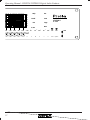
13. DIMENSIONS
4.24RD Remote
5.36
6.50
14. SPECIFICATIONS
Input
Max. Input Level
Output
Max. Output Level
Frequency Response
THD
Dynamic Range
Signal Present & Clip
Audio Sampling Rate
Propagation Delay
Remote Distance
AC Requirements
Environmental
Model
4.24G
4.24RD
4.24GS/PS
2.24GS/PS
Active Balanced, 18KΩ
+20dBu
Pseudo-Balanced, 100Ω
+20dBu
20Hz to 20KHz, ±0.25dB
<0.01% @ 1KHz, +20dBu
>110dB 20Hz - 20KHz unweighted
-15dBu, +20dBu
48KHz
1.46mS
>1000 ft
90-125VAC, 50/60Hz,
180VAC - 250VAC 50/60Hz switchable
40°F - 120°F (4°C-49°C)
Non-condensing
Weight
14 Lbs
5 Lbs
13 Lbs
9 Lbs
Power
30W
NA
27W
20W
19
Operating Manual - PROTEA SYSTEM II Digital Audio Products
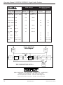
4.24G Settings
Slave Switch Settings
Digital Audio Products
On Back Panel
System
Data
Configuration Connectors
Data Config Master/MIDI/
Switch On Back RS232 UserPref
Switch "A"
Switch "B"
(Baud Rate)
(Data Config)
Out
Out
Out
Out
Out
Out
In
Out
4.24G Only
Multiple 4.24G
(XLR or MIDI)
Out
Out
MIDI
Master on 1st
4.24G + Remote
XLR
Out
MIDI
4.24G + Slaves
XLR
Out
Master
Slaves + Remote
XLR
4.24G + Slaves +
Remote
XLR
Out
MIDI
PC + 4.24G
RS-232
Out
RS-232
PC + 4.24G +
Slaves
RS-232
XLR
In
RS-232
PC + 1 Slave
RS-232
In
Out
PC + Multiple
Slaves
RS-232 to 1st
XLR to others
In
In
In on 1st Slave
Out on others
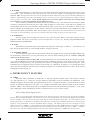
PROTEA SYSTEM CONFIGURATION TABLE
Protea Audio Path
Block Diagram
Signal
Detector
Master Gain
A/D
Delay
*
Limiter
Clip Buss
Clip
Detector
Clip Buss
Shelves
EQ
HPF
(Parametric Only)
24dB/oct
*
Limiter
LPF
D/A
24dB/oct
Gain
Reduction
Input
* There is only one limiter per channel,
which is switchable to either Pre or Post.
Output
Meter
Display
ASHLY AUDIO INC. 847 Holt Road Webster, NY 14580-9103
Phone: (716) 872-0010 Fax: (716) 872-0739
Toll Free (800) 828-6308 Internet: www.ashly.com
1999 by Ashly Audio Corporation. All rights reserved worldwide.
20
PROTEA Rev 2
Printed in USA 12/99