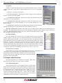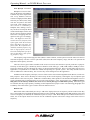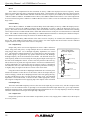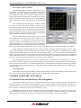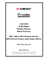
1
Digital Audio Products
ne24.24M
24 Bit Digital
Multiple Channel
Matrix Processor
WR-1, WR-2, WR-5 Remote Controls
GPO General Purpose Logic Output Option
Operating Manual
ASHLY AUDIO INC.
847 Holt Road Webster, NY 14580-9103 Phone: (585) 872-0010
Toll-Free: (800) 828-6308 Fax: (585) 872-0739 www.ashly.com
Operating Manual - ne24.24M Matrix Processor
Table Of Contents
2
1
INTRODUCTION . . . . . . . . . . . . . . . . . . . . . . . . . . . . . . . . . . . . . . . . . . . . . . . . . 4
2
UNPACKING . . . . . . . . . . . . . . . . . . . . . . . . . . . . . . . . . . . . . . . . . . . . . . . . . . . . . . 4
3
AC POWER REQUIREMENTS . . . . . . . . . . . . . . . . . . . . . . . . . . . . . . . . . . . . . 4
4
FRONT PANEL FEATURES . . . . . . . . . . . . . . . . . . . . . . . . . . . . . . . . . . . . . . .
4.1 RS-232 Dataport . . . . . . . . . . . . . . . . . . . . . . . . . . . . . . . . . . . . . . . . . . . . . . . . .
4.3 Preset Number . . . . . . . . . . . . . . . . . . . . . . . . . . . . . . . . . . . . . . . . . . . . . . . . . . .
4.4 Main Input Channel LEDs . . . . . . . . . . . . . . . . . . . . . . . . . . . . . . . . . . . . . . . . .
4.5 Main Output Channel LEDs . . . . . . . . . . . . . . . . . . . . . . . . . . . . . . . . . . . . . . . .
4.6 Expansion Module LEDs . . . . . . . . . . . . . . . . . . . . . . . . . . . . . . . . . . . . . . . . . .
5
5
5
5
5
5
5
REAR PANEL FEATURES . . . . . . . . . . . . . . . . . . . . . . . . . . . . . . . . . . . . . . . . .
5.1 Input Connections . . . . . . . . . . . . . . . . . . . . . . . . . . . . . . . . . . . . . . . . . . . . . . . .
5.2 Output Connections . . . . . . . . . . . . . . . . . . . . . . . . . . . . . . . . . . . . . . . . . . . . . .
5.3 Expansion Modules . . . . . . . . . . . . . . . . . . . . . . . . . . . . . . . . . . . . . . . . . . . . . . .
5.4 Logic Inputs/Preset Recall . . . . . . . . . . . . . . . . . . . . . . . . . . . . . . . . . . . . . . . . .
5.5 Ethernet Control Jack . . . . . . . . . . . . . . . . . . . . . . . . . . . . . . . . . . . . . . . . . . . . .
5.6 0-5V Remote Level Control . . . . . . . . . . . . . . . . . . . . . . . . . . . . . . . . . . . . . . . .
5.7 RS-232 Dataport . . . . . . . . . . . . . . . . . . . . . . . . . . . . . . . . . . . . . . . . . . . . . . . . .
5.8 Data In/Data Out Connection . . . . . . . . . . . . . . . . . . . . . . . . . . . . . . . . . . . . . . .
5.9 Factory Reset Switch . . . . . . . . . . . . . . . . . . . . . . . . . . . . . . . . . . . . . . . . . . . . .
5.10 AC Inlet and Power Switch . . . . . . . . . . . . . . . . . . . . . . . . . . . . . . . . . . . . . . .
6
6
6
6
6
6
7
7
8
8
8
6
EXPANSION MODULE INSTALLATION . . . . . . . . . . . . . . . . . . . . . . . . . . . . 8
7
PROTEA NE SOFTWARE . . . . . . . . . . . . . . . . . . . . . . . . . . . . . . . . . . . . . . . . . . 9
7.1 How to Get Protea System Software . . . . . . . . . . . . . . . . . . . . . . . . . . . . . . . . . 9
7.2 Connecting Using Ethernet . . . . . . . . . . . . . . . . . . . . . . . . . . . . . . . . . . . . . . . 10
7.3 Connecting Using RS-232 . . . . . . . . . . . . . . . . . . . . . . . . . . . . . . . . . . . . . . . . 10
8
AUDIO FUNCTIONS . . . . . . . . . . . . . . . . . . . . . . . . . . . . . . . . . . . . . . . . . . . . . 10
8.1 Input Audio Functions . . . . . . . . . . . . . . . . . . . . . . . . . . . . . . . . . . . . . . . . . . . 10
8.2 Output Audio Functions . . . . . . . . . . . . . . . . . . . . . . . . . . . . . . . . . . . . . . . . . . 14
9
OTHER SOFTWARE FUNCTIONS . . . . . . . . . . . . . . . . . . . . . . . . . . . . . . . .
9.1 Channel Preset File Management . . . . . . . . . . . . . . . . . . . . . . . . . . . . . . . . . .
9.2 Copying Settings to Another Input or Output . . . . . . . . . . . . . . . . . . . . . . . . .
9.3 Security . . . . . . . . . . . . . . . . . . . . . . . . . . . . . . . . . . . . . . . . . . . . . . . . . . . . . . .
9.4 Program Upgrade . . . . . . . . . . . . . . . . . . . . . . . . . . . . . . . . . . . . . . . . . . . . . . .
17
17
18
18
18
Operating Manual - ne24.24M Matrix Processor
10 REMOTE CONTROL . . . . . . . . . . . . . . . . . . . . . . . . . . . . . . . . . . . . . . . . . . . . .
10.1 WR-1 Volume Control . . . . . . . . . . . . . . . . . . . . . . . . . . . . . . . . . . . . . . . . . .
10.2 WR-2 Contact Closure Preset Recall . . . . . . . . . . . . . . . . . . . . . . . . . . . . . .
10.3 WR-5 Programmable Zone Controller . . . . . . . . . . . . . . . . . . . . . . . . . . . . .
18
18
19
19
11 GPO LOGIC OUTPUT WIRING . . . . . . . . . . . . . . . . . . . . . . . . . . . . . . . . . . . . 21
12 TROUBLESHOOTING . . . . . . . . . . . . . . . . . . . . . . . . . . . . . . . . . . . . . . . . . . . . 21
12.1 Audio Problems . . . . . . . . . . . . . . . . . . . . . . . . . . . . . . . . . . . . . . . . . . . . . . . . 21
12.2 Data Communications Problems . . . . . . . . . . . . . . . . . . . . . . . . . . . . . . . . . . 21
13 DIMENSIONS . . . . . . . . . . . . . . . . . . . . . . . . . . . . . . . . . . . . . . . . . . . . . . . . . . . . 21
14 SPECIFICATIONS . . . . . . . . . . . . . . . . . . . . . . . . . . . . . . . . . . . . . . . . . . . . . . . . 22
15 WARRANTY INFORMATION . . . . . . . . . . . . . . . . . . . . . . . . . . . . . . . . . . . . . 22
16 TYPICAL APPLICATIONS . . . . . . . . . . . . . . . . . . . . . . . . . . . . . . . . . . . . . . . . 23
The lightning flash with arrowhead
symbol, within an equilateral triangle, is
intended to alert the user to the presence
of uninsulated "dangerous voltage" within
the product's enclosure that may be of
sufficient magnitude to constitute a risk
of electric shock to persons.
CAUTION
RISK OF ELECTRIC SHOCK
DO NOT OPEN
The exclamation point within an eqilateral
triangle is intended to alert the user to the
presence of important operating and
maintenance instructions in the literature
accompanying the device.
TO REDUCE THE RISK OF ELECTRIC SHOCK, DO NOT
REMOVE COVER. NO USER SERVICEABLE PARTS INSIDE.
REFER SERVICING TO QUALIFIED SERVICE PERSONNEL.
TO REDUCE THE RISK OF FIRE OR ELECTRICAL SHOCK,
DO NOT EXPOSE THIS APPlIANCE TO RAIN OR MOISTURE.
TO REDUCE THE RISK OF FIRE, REPLACE ONLY WITH
SAME TYPE FUSE. REFER REPLACEMENT TO QUALIFIED SERVICE PERSONNEL.
WARNING:
THIS APPARATUS MUST BE EARTHED
3
Operating Manual - ne24.24M Matrix Processor
1. INTRODUCTION
Thank you for your purchase of the Protea ne24.24M. The Protea ne24.24M Matrix Processor uses modular
expansion cards to provide up to twenty-four channels of audio matrixing and processing, along with provisions for
remote control and logic output. The base unit offers a four-input/four-output configuration. Each input and output
expansion card has individual DSP processing allowing expansion of the base unit’s total inputs or outputs four channels at a time. In addition, an eight channel general purpose logic control output expansion card is available for controlling lighting or AV equipment through the Protea NE Software, or by recalling presets.
Expansion cards, meaning inputs, outputs, or a logic output card are easily installed in the field without the need
to reset switches or reprogram the device.
Input channel processing blocks include: Mic Preamp with up to 60dB Gain, 48V Phantom Power and “Touch to
Talk” switching, Input Level with Polarity, two different Remote Level Control choices, Time Delay, Fifteen Band Fully
Parametric EQ, Noise Gate, Autoleveler, and Ducker.
Output channel processing blocks consist of: Cross Point Mixer, HPF/LPF, Delay, fifteen EQ Filters, Gain,
Remote Level Control, and Limiter. The cross point mixer in the output section allows you to route any input to any
output at any level and mute any input at any output without affecting the true input configuration. The HPF/LPF
crossover section offers Bessel, Butterworth and Linkwitz-Riley filters with 12, 18, 24 and 48dB octave slopes.
Matrixing allows you to route any input to any output and control individual levels once they have been assigned.
Fixed path architecture and extensive processing power per channel will reduce the amount of time it takes to set up the
system.
Programming is accomplished using Ashly’s Protea NE Software on a PC or PDA platform via standard 10/
100BASE-T Ethernet communication. The absence of front panel controls along with multi-level software security
assures a tamperproof audio system. Whether designing or installing a system for corporate boardrooms, restaurants,
courtrooms, houses of worship, left/center/right theatres, auditoriums or conference centers, the Protea ne24.24M will
more than satisfy requirements for any zoned system requiring input/output matrixing with signal processing. Factory
presets for many typical sound install applications are available on the Ashly web site as a starting point to set your own
system requirements.
Connectors are euroblock for all audio inputs and outputs, eight Logic Inputs for preset recall, eight channels of
remote DC level control, and a data connection for Ashly’s WR-5 active remote. Ethernet and RS-232 use RJ451 and
DSub 9 connectors respectively.
2. UNPACKING
As a part of our system of quality control, every Ashly product is carefully inspected before leaving the factory to
ensure flawless appearance. After unpacking, please inspect for any physical damage. Save the shipping carton and all
packing materials , as they were carefully designed to reduce to minimum the possibility of transportation damage
should the unit again require packing and shipping. In the event that damage has occurred, immediately notify your
dealer so that a written claim to cover the damages can be initiated.
The right to any claim against a public carrier can be forfeited if the carrier is not notified promptly and if the
shipping carton and packing materials are not available for inspection by the carrier. Save all packing materials until the
claim has been settled.
3. AC POWER REQUIREMENTS
Note: The AC power switch for model ne24.24M is on the back panel. The Protea ne24.24M uses a universal
input power supply which will accept any line voltage from 90VAC to 240VAC, 50-60Hz, and is resistant to voltage
dips, or "brown outs". A standard IEC-320 grounded AC inlet is provided on the rear panel to accept the detachable
power cord. Never remove the AC earth ground connection to the ne24.24M. In the event of fuse failure, refer the
product to a qualified service technician for fuse replacement, replacing only with the same type and rating fuse.
4
Operating Manual - ne24.24M Matrix Processor
4. FRONT PANEL FEATURES
4.1 RS-232 Dataport
The ne24.24M has two RS-232 dataports wired in parallel, one on the front panel and one on the back, for connecting to a computer for software control. See section 7.3 for details on connecting to a computer.
4.2 Com LED
This green LED lights for a few seconds whenever there is communication
activity to the unit from a host PC.
4.3 Preset Number
This LED and switch select and display the current ne24.24M preset number (1-35). The switch can be disabled from there as well. When set to preset
number mode, the green LED near the switch is lit. To select a new preset, press
and hold the switch until the desired preset number is displayed. When the preset button is released, the new preset is loaded.
4.4 Main Input Channel LEDs
The ne24.24M base unit has four fixed input channels, each of which can be
routed to any combination of output channels. Each input channel's two color Sig
LED indicates input signal level of -20dB (green), or +20dB clip (red) respectively.
The Sig LEDs detect signal levels after any gain adjustments are made within the
ne24.24M preamp section. The red input mute LED becomes lit when an input
channel is muted through software.
4.5 Main Output Channel LEDs
The four fixed output channels on the ne24.24M have three color LEDs to
indicate signal, limiter threshold, and clip. The green signal LED indicates -20dB
output level. The amber limiter threshold LED depends on settings established within
Protea System Software, and, assuming the limiter is active, indicates that sufficient
signal level has been reached for the limiter to begin the process of gain reduction.
Clipping occurs at +20dB and is indicated by a red LED. The red output mute LED becomes lit when an output channel
is muted through software control.
4.6 Expansion Module LEDs
The ne24.24M base model is expandable by up to 16 additional inputs or outputs. Expansion modules of four
inputs or four outputs each can be field installed by a qualified service technician. If an expansion card slot has been
filled, its respective LED (EXP 1, EXP 2, etc.) is automatically lit. The LED indicators on unused expansion slots
remain inactive.
5
Operating Manual - ne24.24M Matrix Processor
5. REAR PANEL FEATURES
5.1 Input Connections
Balanced input signals are connected to the ne24.24M using the included
euroblock connector. A flat blade screwdriver is required to connect a stripped
wire lead to the external connector piece, which is then inserted into the rear
panel Euro Block receptacle. It is important that both (+) and (-) inputs are properly terminated or signal loss and noise may result. In other words, if an unbalanced input signal is used, connect the signal to the (+) input, and connect the
ground wire to both the (-) and ground connection.
Euroblock
Connector
System
5.2 Output Connections
Like the inputs, output connections are made using the included euroblock connector. All outputs are servo balanced, and may be wired balanced or unbalanced. For unbalanced output connections, use (+) and ground and tie (-) to
ground.
5.3 Expansion Modules
The ne24.24M base model is expandable by up to 16 additional inputs or outputs, as well as a single module card
used for eight general purpose logic outputs (GPO). Expansion modules of four inputs or four outputs each can be
installed in any expansion slot. Input expansion modules use green euroblock connectors, while output expansion
modules use black connectors. Removable metal plates cover unused expansion slots on the back panel. The optional
Logic Output card (GPO) is used to drive preset controlled relays or another device’s logic control inputs. The GPO
comes with a function and wiring sticker which must be placed on the ne24.24M back panel above the Input/Output slot
where the GPO option is installed. Only one GPO can be installed in a ne24.24M.
5.4 Logic Inputs (Preset Recall)
There are no user controls on the ne24.24M, making it ideal for permanent installations where security is an issue.
There may be times, however, where real time variables require changes in system settings, such as EQ, gain, and delay
settings changing when a room size changes. For these types of changes, the ne24.24M offers the ability to recall up to
eight different presets, or switch other events such as a mic input “push to talk” using contact closures. Contact closures
are nothing more than external, user installed switches that, when closed, recall a previously defined preset which at
once applies changes to the settings of all inputs and outputs. The switches can be anything from a rotary switch on a
control room panel, to automatic door sensors scattered throughout a conference center, to a microphone key switch, etc.
Contact closures allow for flexibility while maintaining a high degree of system security.
6
Operating Manual - ne24.24M Matrix Processor
To use contact closure switching, up to eight presets (1-8) must first be defined according to the needs of the
installation. To use the mic input “Push To Talk” feature, select the “Push To Talk Mic” checkbox in the Protea NE
Software’s mic preamp dialog box. The preset recall feature for that contact closure is then deactivated. Switches are to
be configured so that closing the switch contact triggers the preset recall event. It doesn't matter if the switch is momentary or latching, the only thing that triggers the event is the transition from open to closed for a given circuit. Closing a
circuit will automatically override any previously recalled presets. Up to eight switches can be used, with all switches
sharing a common ground connection. The number below the nine pin Euro Block contact closure connector equals the
number of the preset which will be recalled when that switch is closed. Always use the ne24.24M contact closure
ground for contact closure switches. Do not connect the ne24.24M contact closure ground to any other external grounds,
as ground loop currents may result.
5.5 10/100 Ethernet Control Jack
Use this RJ-45 jack to connect directly to a computer or to a 10/100 Base-T ethernet network using Proteane
software for access to the comprehensive suite of device setup, audio controls, and monitoring functions.
5.6 0-5V Remote Level Control
Any of the inputs or outputs on the ne24.24M can have their levels remotely controlled through this simple DC
control port. Use the provided +5VDC and Ground (pins 9 and 10), along with a potentiometer, switched resistor
network, or relay (for muting), to return a DC voltage to the desired input or output control pin. Using Protea NE
Software, each remote level control pin can be assigned any combination of inputs or outputs to create up to eight remote
control groups (see sec 11.1).
The remote level control can only attenuate the signal, it can not provide gain, so properly set up the gain structure
within the ne24.24M before using remote level control. +5V on any control pin has no attenuating effect, while 0V
referenced to the connector ground fully attenuates the signal. Do not connect the remote level control ground to any
other external grounds.
5.7 RS-232 Dataport
The ne24.24M has two RS-232 dataports, wired in parallel, with one on the front panel and one on the back, for
connecting to a computer for AMX, Crestron, or other third party controllers. Control data for the ne24.24M uses the
RS-232 protocol, and does not support the MIDI baud rate. Supported baud rates are 9600bps and 38,400bps.. See
section 7.3 for details on connecting to a computer.
7
Operating Manual - ne24.24M Matrix Processor
5.8 Data In/Data Out Connection
The Data In and Out connectors are used for connecting the ne24.24M to the Ashly WR-5 active wall remote
controller or RD-8C.
5.9 Factory Reset Switch
Factory reset is used to clear all user defined preset names and control values and reset them to their original
factory settings. Factory reset to the ne24.24M is accomplished by pressing and holding a recessed switch on the back
panel during power up. The switch is found in a small hole labelled “Reset”. There is a 10 second countdown in the
front panel LED display to indicate a factory reset is about to occur. Releasing the switch or shutting off power at any
time during the countdown will stop the factory reset from occurring. At the end of the countdown, the letters "Fr" flash
in the display for about 20 seconds until factory reset is complete. In addition to resetting all presets to factory default,
any password or security settings will be lost when a factory reset is performed.
5.10 AC Inlet and Power Switch
A detachable AC power cord is used on the ne24.24M. Since the internal universal power supply works from 90
to 240 VAC 50-60Hz, the only change necessary for use with a different AC mains connection is the appropriate AC
power cord. The AC power switch is found on the back of the unit.
6. EXPANSION MODULE INSTALLATION
The Ashly ne24.24M can be ordered from the factory with expansion modules pre-installed to suit the application,
or as a 4 x 4 base unit. Should the need arise to add input or output capacity at a later time, as well as logic output
function, additional modules can be purchased and easily installed in the field.
There are a total of four expansion slots available, and each slot accepts either an input, an output, or a logic
output module (GPO). The ne24.24M as well as Protea NE Software autodetect if a slot has been filled, and whether it
is an input, output, or logic output. The software interface automatically updates to reflect the current ne24.24M expansion slot configuration. The logic output expansion module can be installed into any slot, however only one logic output
module can be installed.
Please note that while field installation is not complicated, there is a risk of ESD (electrostatic discharge) damage
to circuit board components if the board is improperly handled.
To install an additional expansion module, refer the following procedure to a qualified service technician:
1.) Remove AC power cord from back of unit and place unit on grounded work surface.
2.) Remove the seven top cover screws and remove cover. Remove expansion slot covers from back panel.
3.) Discharge any personal static by touching a grounded object. Carefully remove the new expansion card and
flat cable from the ESD protective bag.
4.) Follow the instructions in the above drawing for installing expansion modules. Ashly recommends placing
input expansion modules starting with EXP1, and placing output expansion modules starting from EXP 4 and working
backwards. This way input and output channels are continuously numbered up from channel 1.
6.) In some cases it may be necessary to remove an existing expansion card before installing a new adjacent one.
Certain motherboard flatcable headers may be inaccessible with modules installed above them.
7.) Make sure all hardware is secure, then replace top cover.
For further information on expansion module assembly or proper ESD protection, please contact the Ashly service
department at 1-800-828-6308.
8
Operating Manual - ne24.24M Matrix Processor
5
Expansion Card Assembly:
4
5
*See ESD Precautions First
1.) Plug ribbon cable into
motherboard header
2.) Plug other end of ribbon
cable into expansion slot
3.) Slide pcb fingers into
slots on back of meter card
4.) Fit Euroblock connectors
through back panel cut-outs
5.) Fasten two back panel
screws
3
2
1
Flatcable(s)
to
Motherboard
EXP4
Expansion Card #4
Inputs 17-20
Outputs 5-8
Logic Outputs 1-8
Expansion Card #3
Input 13-16
Outputs 9-12
Logic Outputs 1-8
EXP3
EXP2
Expansion Card #2
Inputs 9-12
Outputs 13-16
Logic Outputs 1-8
EXP1
Expansion Card #1
Inputs 5-8
Outputs 17-20
Logic Outputs 1-8
7. PROTEA NE SOFTWARE
Ashly offers a powerful software interface for the Windows PC environment, as well as any PDA device running
Windows Mobil 05, providing control for the ne24.24M Matrix Processor, and many other Ashly digital audio processors and power amplifiers. All controls are intuitively represented in a user friendly way, and comprehensive on-line
help is available for all key functions.
7.1 How to get Protea NE Software
Protea NE Software is shipped free with each new Protea ne24.24M, can be downloaded from the Ashly web site,
or can be purchased directly from Ashly for a nominal handling fee.
9
Operating Manual - ne24.24M Matrix Processor
7.2 Connecting the ne24.24M to a computer using Ethernet
Ethernet is the preferred data protocol for computer control. A standard RJ-45 jack is used for connecting directly
to a PC, PDA, or 10/100 Base-T network.
7.3 Connecting the ne24.24M to a computer using the RS-232 Dataport
The ne24.24M is optimally designed for use with ethernet control, however it remains backward compatible to
systems using RS-232 control. In other words, older Protes System Software (or other) based installs using RS-232 will
work fine with a new ne24.24M. If, on the other hand, the ne24.24M needs RS-232 control while still in a networked
ethernet system using Protea NE Software, add a 24.24M (not the ne24.24M) from the <Add Item> menu in Protea NE
Software and set the unit up accordingly using the self-launching older Protea System Software. RS-232 and ethernet
will run concurrent on the same unit.
For RS-232, a D-Sub nine pin female to male connector cable is used to connect to the ne24.24M. An active USB
to RS-232 converter can be purchased at computer stores if necessary. Here are the suggested steps for connecting the
ne24.24M using RS-232:
1) Plug the RS-232 cable into an available serial port on the PC or control unit.
2) Plug the other end of the cable into either the front or back RS-232 Dataport on the ne24.24M.
3) Turn on the power to the ne24.24M.
4) Open Protea System Software (version 6 .4 or higher), not the Ethernet based Protea NE Software.
5) Go to the <Devices> menu and select <ne24.24M>.
6) Select the appropriate COMM port (Comm 1-16).
7) Select desired Baud rate (9600bps or 38,400bps). Note that 38,400bps is only supported by the ne24.24M.
8) Go to the <Communications> menu and select <Enable Communications>.
9) The connection should now be established. The unit will communicate on any device channel (Channel 1-16)
in the Protea System Software (see sec. 4.2.)
8. AUDIO FUNCTIONS
Editing of audio controls is done primarily in Protea System Software. Input and output expansion cards are
autodetected, and the software automatically updates to display the current ne24.24M status. Note: Accidental, potentially destructive loudspeaker damage can occur when abrupt changes are made to EQ, filter, or level controls, so plan
carefully before making radical changes to a live sound system.
8.1 Input Audio Functions
The following functions are available on all inputs; Mute, Preamp Gain, Input Gain,
Delay, EQ, Noise Gate, Autoleveler, Ducker, and Matrix Routing.
8.1a Input Mute
This turns off the input channel without changing gain settings. When an input channel
is muted, that channel’s red mute LED on the face panel is lit.
8.1b Input Preamp
This determines the up-front analog gain to an input signal. A good rule of thumb is to
allow 20dB of headroom above the nominal input signal level. Clipping occurs at +20dBu, so
a microphone nominally generating a -40dBu signal should have +40dB of gain, a 0dBu line
level input would be set to 0dB gain, etc.
10
Operating Manual - ne24.24M Matrix Processor
8.1c Phantom Power
+48V Phantom power for condenser microphones can be provided to individual channels by checking the <+48V
Phantom Power> box in the preamp block for a given channel.
8.1c Push To Talk Mic
This check box and drop down menu selects the back panel logic input to serve
as a contact closure input channel engage.
8.1d Input Gain
Different from the Preamp block, input Gain adjusts signal level from +12dB to
Off. Due to limitations within the graphical interface, fine tuning gain settings in
0.1dB steps is accomplished using the <up/down arrows> on the keyboard. Changes
of 3dB are quickly accomplished using <PageUp/PageDown> buttons. To instantly
return a gain setting to 0dB, press <Ctrl + click>.
8.1e Input Delay
In large installations or outdoor venues there are often many speakers in various locations to get the best coverage possible. Since sound travels relatively slow
through air (1130 ft/s at 20 deg. C), multiple loudspeaker locations can create a
situation where the original audio signal, simultaneously leaving all loudspeakers, arrives at a single point in the venue at several different times.
Needless to say this causes problems, and what may be crystal clear sound
directly in front of any one loudspeaker can be unintelligible at the farther
reaches of the venue with direct line-of-sound to multiple loudspeaker
sources.
The solution is to delay the audio signal to the loudspeakers located further away from the primary source, so that
sound comes out of the distant loudspeakers at the exact time that sound from the main loudspeakers arrives. Within the
Protea ne24.24M, up to 682 milliseconds of time delay are available on each input channel, allowing secondary loudspeakers to be time aligned with the primary speakers up to 771 feet (235m) away. Set the TEMP text box to the current
air temperature to get the most accurate display of delay distance.
Fine tuning delay settings is accomplished using the <up/down arrows> on the keyboard. Course changes of 1mS
are quickly accomplished using <PageUp/PageDown> buttons. For an explanation of short time delay uses, see section
9.2c.
8.1f Input EQ
The Protea ne24.24M input EQ section offers 15 custom filters per input. Types of filters available for each band
include parametric, 1st order and 2nd order low shelf, 1st order and 2nd order high shelf, and all-pass.
Shelving EQ filters: 1st order filters use a gentle 6dB per octave slope, while 2nd order filters use a 12dB per
octave slope for a more pronounced boost or cut. All shelving filters have a boost/cut range of +/-15dB. Low shelving
filters have a frequency range from 20Hz through 2kHz, and the high shelving filters range from 3.886kHz through
20kHz. Shelving filters are most useful as broad tone controls to boost or cut the high end or low end of an audio signal's
frequency content. Because they affect a wider spectrum of audio, they are not as suitable for feedback control as
parametric filters. Course and fine tuning of shelving filters can be performed using <page up/page down> and the <up/
down arrows> on the keyboard.
Parametric EQ filters: These are peak filters with the ability to control boost or cut, frequency center, and bandwidth, also called “Q” for this type of filter. Think of one band of parametric EQ as a single graphic equalizer fader
except that the frequency is variable, not fixed, and that the bandwidth, or how "wide" the filter affects the frequency
spectrum at the center frequency, is completely variable. The smaller the bandwidth (higher Q), the less the audio signal
11
Operating Manual - ne24.24M Matrix Processor
on either side of the frequency center is boost or cut,
whereas a larger "wider"
bandwidth (lower Q) produces an audible change to
the overall tone of a signal.
Parametric filters are best
used to hunt down and eliminate problem feedback frequencies, add or remove a
characteristic "hot spot" from
microphones, or clean up
room resonance situations. It
is well worth the time becoming proficient with parametric EQ filters, as they offer
the best solution to many EQ
problems.
Protea ne24.24M parametric filters have a boost/cut
range of +15dB to -30dB.
There is more cut than boost
because one of the more common uses for parametric filters is to dramatically cut, or "notch out", very narrow frequencies (low bandwidth) in order to eliminate system feedback problems.
Every parametric EQ filter has a center
frequency. The factory default is 1kHz, but each
filter is adjustable from 20Hz to 20kHz in 1Hz
steps. Carefully sweeping a narrow bandwidth
filter through a problem feedback area, with just
a slight boost, is a quick way to find the exact
frequency causing feedback trouble. Once the
offensive frequency has been found, cut the
filter's level, and then adjust the bandwidth as
narrow as possible while still eliminating the
feedback problem. Bandwidth is adjustable
from about 1/64 octave to four octaves, and the
lower the bandwidth (higher Q), the less audible
the filter action will be. Finding the problem
frequency is relatively easy, but finding the best
combination of cut and bandwidth takes a little
practice. Again, it is well worth the time getting comfortable with the notching procedure,
so that problems can be quickly addressed with
a sufficient but minimal amount of corrective
EQ.
All Pass filters: All pass filters have no
effect on frequency amplitude, but rather are
used to adjust the phase response of the signal
at a given frequency, and are often used in conjunction with a frequency-domain filter to correct phase changes. At low frequencies, there
12
Operating Manual - ne24.24M Matrix Processor
is 0 degree phase shift, at the All Pass filter center frequency there
is -180 degrees of phase shift, and at high frequencies there is -360
degrees of phase shift.
Each input channel has an EQ On/Off button for all filters,
and in turn each filter band has its own bypass button. The Flatten
Curve function returns all filters to 0dB, but preserves the frequency
and bandwidth of any used filters.
8.1g Noise Gate
Noise gates are used to minimize unwanted or ambient low
level signal from an individual mic input. THRESHOLD is the
level above which an input signal will pass through, and below which
its signal is turned off. RANGE is the amount of attenuation in dB
which the noise gate attenuates the signal when the gate is off.
ATTACK and RELEASE control the time characteristics of the
gating action. Attack sets the amount of time it takes for the gate to
open or gated signal to turn on. Release sets the time required for
the gate to close back up when the input signal falls below threshold.
8.1h Autoleveler
An Autoleveler is a dynamics processor used to automatically boost or cut a signal to a user defined target level.
TARGET LEVEL is the primary setting in an autoleveler, as it determines the desired constant level to which an input is
boost or cut. Both basic mode and advanced mode utilize the target level control, but basic mode simplifies setup. In
BASIC MODE, target level, action, and maximum gain are the available controls. ACTION is selectable to gentle,
normal, or aggressive, and automatically adjusts the following controls found in advanced mode:
Action
Aggressive
Normal
Gentle
Ratio
10:1
4:1
2:1
Hold Time
0 Sec
1 Sec
2 Sec
Thr =
Gain Incr. Rate
20ms/dB
50ms/dB
100ms/dB
Gain Dec. Rate
5 ms/dB
10 ms/dB
20 ms/dB
Max Gain
(1/ratio - 1)
MAXIMUM GAIN controls the threshold below target using the following formula:
In ADVANCED MODE, THRESHOLD BELOW TARGET determines
the input signal level relative to the target level, above which the autoleveler
increases gain, and below which no action is taken. RATIO is defined as the
relationship of input level change in dB to output level change in dB. It is a
measure of how aggressively the autoleveler changes the gain to maintain a
constant output target level. GAIN INCREASE RATE and GAIN DECREASE
RATE are used to prevent sudden, choppy sounding level changes to an input
signal having a wide dynamic range. HOLD TIME is used in conjunction with
gain change rate, and is defined as the time after the input signal falls below
the threshold during which the autolever’s gain is held constant before it returns to unity gain. The purpose is to reduce the amount of gain “chatter” and
abrupt signal cutoff when the input signal is hovering around the threshold
level. Advanced settings which are different than the three Basic action settings results in a USER DEFINED display in the basic action control.
13
Operating Manual - ne24.24M Matrix Processor
8.1i Ducker
A Ducker is used to attenuate the level of selected input channels when one or more
"Trigger" inputs have signal present. Input channels can be set to one of four ducker
modes:
1.) BYPASS - no ducking action applies.
2.) DUCKED PROGRAM - signal present on other "Trigger" selected input channels act to attenuate this input channel.
3.) LOW PRIORITY TRIGGER - signal present on this input channel attenuates all
other inputs set to "Ducked Program".
4.) HIGH PRIORITY TRIGGER - signal present on this input channel fully attenuates all other inputs set to "Ducked Program", as well as all other channels set to "Low
Priority Trigger".
5.) FILIBUSTER - signal present on this channel fully attenuates all other channels
until the signal drops below its threshold to allow other channels to come on.
TRIGGER THRESHOLD determines the signal level on a trigger input at which point the ducked program is
attenuated. DUCKING DEPTH determines how much attenuation is applied to input channels set up as ducked program. DUCKING RELEASE determines the rate at which the attenuation returns to 0dB
after the trigger input signal has stopped.
8.1j Matrix Routing
Any input channel can be routed to any or all output channels, likewise any output
channel can have as its source any or all inputs, limited only by the installed capacity of
input or output expansion modules. To route an input to an output, click and drag from the
input connect box to the desired output connect box (click and drag routing works in both
directions). To delete a connection, click on the connect line and press <Delete> on the
keyboard, or right click on the connection line for the delete prompt. To quickly perform
multiple routing connections or disconnections to the current input channel, hold <Ctrl> and
click on desired individual output channel connect boxes to toggle them on or off. Anytime
a connection is made, the corresponding output mixer level is set to “-inf”, (off).
8.1k Remote Level Control
Each channel can be remotely attenuated through the back panel 0-5V Remote Level
Control pins, or by an Ashly RD8C active remote attenuator connected to
the 4-pin data connector on the back. The Remote Level Controls dialogue
box then allows arbitrary assignment of the remote’s attenuator channels
to the ne24.24M’s audio channel.
8.2 Output Audio Functions
The following functions are available on all outputs: Mixer, High
Pass/Low Pass Filter, Delay, EQ, Gain, Limiter, and Mute.
8.2a Output Matrix Mixer
Output channels can have any or all inputs as sources, and the output
matrix mixer allows the level of each connected input to be adjusted in the
“matrix mix” to each output. Note that for a given output, unlinked inputs
are disabled in the mixer. Adjustment range is from +12dB to off. To set
a level control to unity (0) within the matrix mixer, select an input level
control by clicking on it and pressing <ctrl> + <click> on the level adjustment control. Individual input channels in the matrix mixer can be muted
independently from the main input or output mute blocks.
14
Operating Manual - ne24.24M Matrix Processor
8.2b Hpf/Lpf - Crossover
Bandpass or crossover functions on the Protea ne24.24M are
available only on the output channels. Every channel's crossover
consists of a high pass filter (HPF)
and a low pass filter (LPF), along
with the frequencies and filter
types used. Each output's crossover section is essentially a
bandpass filter, making it necessary for the user to map out ahead
of time which outputs will be used
for the various frequency bands,
and set the overlapping filter frequencies and types accordingly.
Note: The High Pass Filter determines the lower frequency limit
of the signal, while the Low Pass
Filter determines the upper frequency limit. Be careful not to accidentally send low frequency signals to high frequency drivers.
Check the loudspeaker specifications to determine a safe operating frequency range.
The frequency range for the high pass filter (HPF) is 20Hz to 20kHz, with an option to turn the filter off at the low
end of the frequency selection. The low pass filter (LPF) offers the same frequency range, with the "off" option at the
high end of the frequency selection.
There are eleven types of filters available in the crossover section, each suited to a specific preference or purpose.
The slope of each filter type is defined by the first characters in the filter type, 12dB, 18dB, 24dB, or 48dB per octave.
The steeper the slope, the more abruptly the "edges" of the pass band will drop off. There is no best filter slope for every
application, so experiment to see which one sounds most pleasing in a specific system. The Ashly default crossover
filter is 24dB/octave Linkwitz-Riley, but of course they can be changed to suit the application.
In addition to the frequency and slope, crossover filters can be selected as having Butterworth, Bessel, or LinkwitzRiley response. These refer to the shape of a filter's slope at the cut-off frequency, affecting the way two adjacent pass
bands interact at the crossover point. 24dB/octave Linkwitz-Riley filters produce a flat transition through the crossover
region, assuming both overlapping filters are set to the same frequency, slope, and response type. 24dB/oct LinkwitzRiley filters are the industry standard, the easiest to use, and the filter type recommended by Ashly. Other filter types
are available, but may require polarity switching or other adjustments for proper results. The following paragraphs offer
a summary of the three filter types as used in the ne24.24M crossovers.
Butterworth
Butterworth filters individually are always -3dB at the displayed crossover frequency and are used because they
have a "maximally flat" passband and sharpest transition to the stopband. When a Butterworth HPF and LPF of the same
crossover frequency are summed, the combined response is always +3dB. With 12dB per octave Butterworth crossover
filters, one of the outputs must be inverted or else the combined response will result in a large notch at the crossover
frequency.
15
Operating Manual - ne24.24M Matrix Processor
Bessel
These filters, as implemented on the ne24.24M, are always -3dB at the displayed crossover frequency. Bessel
filters are used because they have a maximally flat group delay. Stated another way, Bessel filters have the most linear
phase response. When a Bessel HPF and LPF of the same crossover frequency are summed, the combined response is
+3dB for 12dB/oct, 18dB/oct, and 48dB/oct Bessel filters, and -2dB for 24dB/oct Bessel filters. One of the outputs must
be inverted when using either 12dB/oct or 18dB/oct Bessel crossover filters or else the combined response will have a
large notch.
Linkwitz-Riley
The 12 dB/oct, 24dB/oct, an 48dB/oct Linkwitz-Riley filters individually are always -6dB at the displayed crossover frequency, however the 18dB/oct Linkwitz filters individually are always -3dB at the displayed crossover frequency. The reason for this is that Linkwitz-Riley filters are defined in terms of performance criterion on the summing
of two adjacent crossover HPF and LPF filters, rather than defined in terms of the pole-zero characteristics of individual
filters. The 18dB/oct Linkwitz-Riley individually are 18dB/oct Butterworth filters in that they have Butterworth polezero characteristics and also satisfy the criterion for Linkwitz-Riley filters.
When a Linkwitz-Riley HPF and LPF of the same crossover frequency are summed, the combined response is
always flat. With 12dB/oct Linkwitz-Riley crossover filters, one of the outputs must be inverted or else the combined
response will have a large notch at the crossover frequency.
8.2c Output Delay
Output delay can be used to time align discrete drivers within a cabinet or
cluster using short delay times, or align multiple drivers in different locations
using longer delay times. For a thorough long-delay explanation, see section
9.1e. The following example illustrates a use of short delay to time align speakers within a group: A typical three way speaker cluster has low end, midrange,
and high frequency drivers all located near one another. The different drivers for
each frequency band are not necessarily the same physical depth with respect to
the front of the loudspeaker cluster, so there exists the problem of the same signals (at the crossover points) arriving at the cluster "wavefront" at different times,
creating undesirable wave interaction such as frequency peaks or cancellation.
The solution in this case, rather than fixing the frequency anomalies with EQ, is
to slightly delay the signal to the drivers closest to the cluster front.
Using the location of the driver diaphragm farthest back as a reference point,
measure the distance to other drivers in the cluster, and set the output delay for
each accordingly, with the driver diaphragm closest to the front getting the longest delay and the driver at the very back getting no delay at all. The minimum
adjustment is 0.02 milliseconds, or about 1/4 inch. When appropriate, always
time align the loudspeakers before applying EQ to the outputs of the ne24.24M.
Short Time Delay
For Driver Alignment
Example: 12 Inches
High - No Delay
Midrange Delay
12 Inches = 0.9mS
Low Delay
8 Inches = 0.6mS
Example: 8 Inches
8.2d Output EQ
The Protea ne24.24M Output EQ section is the same as the input EQ (see section 9.1f), with the exception of the
ability to view the combined effect of input EQ for each installed and linked input channel to a given output channel.
Within the output EQ frame, each installed and linked input channel has its own <Overlay Input EQ> check box, through
which the interaction between input and output EQ is displayed.
8.2e Output Gain
Output Gain operates in the same manner as Input Gain (section 9.1d), ranging from +12dB to Off, with an option
to reverse polarity.
16
Operating Manual - ne24.24M Matrix Processor
8.2f Output Compressor/Limiter
A full function compressor/limiter is included on each output channel. A limiter is commonly used to prevent transient
audio signal spikes from damaging loudspeakers, manage analog and digital recording levels, optimize broadcast levels, or
"thicken" the sound of an audio source (compression). The adjustable parameters include Limiter In/Out, Threshold, Ratio,
Attack Time, Release Time, and Link Group, and Attenuation
Bus.
The ne24.24M limiter threshold range is -20dBu to +20dBu,
or -24VU to +16VU if the metering option is selected to VU.
The Threshold control determines the signal level above which
gain reduction begins, and is indicated by an amber LED (S/L)
on the ne24.24M face panel, as well as indicated in the Matrix
Meters in software. Increases in audio level above the threshold
will be reduced according to the ratio settings.
The Ratio control determines the amount of gain reduction
above limiter threshold. Ratio ranges from a gentle 1.2:1 to a
very abrupt INF:1. To illustrate how the ratio control works,
imagine a commonly used loudspeaker protection ratio of 10:1,
which means that for every input signal increase of 10 dB above
threshold, the output level will only increase by 1dB. The higher
the ratio, the more pronounced the audio effect, so use the lowest ratio possible to sufficiently address the problem.
Attack and Release settings adjust the time it takes the limiter to engage and then disengage when the signal
increases above threshold and then subsequently falls back below threshold. Attack time is adjustable from 0.2ms/dB
through 50ms/dB, while release time ranges from 5ms/dB through 1s/dB. A very fast attack time can sound unnatural,
while a very long attack time can miss some of the initial transient. Similarly, a very short release time can make the
audio sound uneven, while a very long release time can create "pumping", or "breathing" characteristics depending on
the kind of signal. Experiment to find the best solution for a given application.
The Attenuation Bus allows up to four output channels within a group to share a threshold detector, so that any
channel with a transient signal above threshold will apply equal gain reduction to all other channels within that group
which is assigned to the link bus. The channel which furthest exceeds threshold will determine the resulting reduction
on all channels selected to the attenuation bus. The channel limiter attenuation bus is particularly useful when processing stereo signals.
8.2g Output Mute
Output Mute turns off an output channel. When an output channel is muted, that channel’s red mute LED on the
face panel is lit. To mute or unmute all outputs at once, go to the <Mute> menu heading.
9. OTHER SOFTWARE FUNCTIONS
9.1 Channel Preset (and Sub Preset) File Management
The Protea ne24.24M will store up to 31 named internal presets, each preset storing control data for all channels
and audio functions. Preset names must be 20 characters or less. While working in Protea NE Software, changes to an
individual preset can be saved to the ne24.24M using <File/Save Preset To Protea>, or saved to the PC using <File/Save
Preset To Disk>. Individual preset files use the extension (*.pne).
Sub Presets: Instead of saving or recalling an entire preset affecting all functions, a sub-preset affecting only a
sub-set of functions may be used. To save a sub-preset, check the boxed labelled <Selected for sub-presets> in the audio
control functions to be stored in the sub preset, and then click <preset options>, then <Save Sub Preset>.
17
Operating Manual - ne24.24M Matrix Processor
Since there are no user controls on the ne24.24M, the only way to load presets is by using Protea NE Software to
recall files saved on either the PC or the ne24.24M. The exception to this is through the use of contact closures or the
Ashly WR-5 wall-mounted remote control. Contact closures can load presets 1-8 from the ne24.24M memory using
switches wired to the rear panel contact closure connector block (see sec. 5.4).
Note: A preset recall event will overwrite any unsaved changes, so be sure the current configuration is saved
before continuing or it will be lost. The ne24.24M always loads the last settings on power-up, so as to preserve any
changes should the power be inadvertently turned off prior to saving a preset.
Caution: A new preset may have dramatically different settings capable of damaging sound system components,
so be careful not to recall the wrong preset while the system is on.
9.2 Copying Settings to Another Input Or Output
To quickly transfer all settings from one input or output to another input or output channel within the same unit,
right click on the channel number and choose from the available options to copy, paste, or link with another channel.
9.3 Security
There are multiple user/multiple levels of protection assignable to the ne24.24M within the software <Security>
pull down menu, from full access to view only, with User ID and Passwords assigned for each available unit. The
ne24.24M security data is stored within the unit, not Protea NE Software. Passwords are case sensitive. Be sure to
write down the password and store in a convenient place for future reference. If the password is forgotten, a password
reset can be done by pressing and holding the factory reset switch for two seconds during power up. Note: Holding the
reset switch for a full 10 seconds during power up will perform a full factory reset, changing all presets to the factory
default.
9.4 Program Upgrade
The ne24.24M Matrix Processor is capable of field flash reprogramming through Ashly Audio’s Protea NE Software. Look under <Device Options> for further details.
10 REMOTE CONTROL
Ashly makes three remote control options for the Protea ne24.24M. All of them are designed to be installed in a
standard wall mount electrical box using a standard cover plate. The WR-1 and WR-2 are passive controls which can
adjust volume or select presets respectively, while the WR-5 (replaces WR-3 and WR-4) is an active control with user
defined function buttons and LED display.
10.1 WR-1 Volume Control
The WR-1 is an assignable, dual potentiometer remote
volume control for the ne24.24M. Each volume control is connected to a terminal block on the WR-1 circuit board, which in
turn must be wired to the ne24.24M back panel euroblock connector labeled "0 - 5 Volt Remote Level Control". Do not
connect the WR-1 remote level control ground to any other
external grounds.
By connecting a volume control to a specific pin (1-8),
that pin can be selected in software under <Options - Define
Remote Level Controls> to control the level of any combination of inputs or outputs. It is possible to simultaneously select the same input or output channel to multiple remote level
control pins. Note, however, that the resulting attenuation on
that channel is cumulative, meaning that channel’s gain is set
by combining the value of all remote level controls mapped to
that channel.
18
Wall Remote Assembly
(WR-1 Shown)
Operating Manual - ne24.24M Matrix Processor
In addition to using a WR-1 as the control device, the remote level control feature can be used for relay activated
muting of selected channels, as in a fire alarm application (see sec. 16). Note: Use Protea System Software version 6.1.4
or higher, and ne24.24M program version 1.5 or higher to allow assignable remote control.
Level control is "attenuate only" meaning that the maximum setting of the control potentiometer (fully clockwise)
results in 0 dB gain of the controlled channel. A label template can be found on the Ashly website for printing input or
output channel names under control of the WR-1 and sliding the paper behind the mylar overlay windows.
The two +5V pins and two ground pins on the WR-1 euroblock connector are tied together on the circuit board, so
it is only necessary to run one +5V line and one ground line to the WR-1 from the ne24.24M. These pins are provided
for daisy-chaining multiple WR-1 controllers (up to four) together. See WR-1 Wiring Diagram on next page.
10.2 WR-2 Contact Closure Preset Recall
The WR-2 allows for remote selection of one of eight possible ne24.24M presets via interlocking push-button
switches. Each pushbutton switch connects to a terminal block pin on the WR-2 circuit board, which in turn must be
wired to the ne24.24M back panel euroblock connector labeled "Preset Recall". Do not connect the WR-2 remote level
control ground to any other external grounds.
The terminal numbers 1-8 correspond to the first 8 Preset Memory locations in the ne24.24M. Pressing a button
will load the corresponding preset. A label template can be found on the Ashly website for printing preset names for the
WR-2 and sliding the paper behind the mylar overlay windows. See WR-2 Wiring Diagram on next page.
10.3 WR-5 Programmable Zone Controller
The WR-5 is a microprocessor based remote control unit for the Protea ne24.24M. Like the WR-1 and WR-2, the
WR-5 is designed to fit into a standard electrical wall box. Up to four WR-5 remotes can be phantom powered from one
ne24.24M, and adding more remotes is possible using an external power supply. Each of six buttons on the WR-5 can be
programmed to engage one of the following functions:
1) Preset recall
2) Preset scroll
3) Channel volume
4) Channel mute
5) Zone input source selection
Programming of each button is done from Protea NE Software when the WR-5 is wired to its host
ne24.24M, and added to the software project page.
Wire the WR-5 from the ne24.24M back panel “WR5 Wiring” jack to the WR-5 Input connector, observing proper pin numbering, and use the WR-5
output “Link” for additional WR-5 connections. The
host ne24.24M is in turn connected to a PC via
ethernet or RS-232. Multiple WR-5 units (up to
four) can be daisy-chained from the same ne24.24M
for discrete control over multiple locations under
the processing control of one ne24.24M. See your
Ashly dealer or visit the Ashly web site at
www.ashly.com for more WR-5 details.
19
Operating Manual - ne24.24M Matrix Processor
WR-1 Wiring Diagram
WR-2 Wiring Diagram
1
2
3
4
ASHLY WR-2
1
*Ch. 2 Gnd/+5
Are Wired To
Ch. 1 Gnd/+5
On WR-1 PCB.
G*
G
12
Common*
34
Common*
1
2
2
CV-2
+5*
CV-1
+5
Connector on
24.24M
Back Panel
3
4
CV-1 To Pin 1-8
CV-2 To Pin 1-8
C
*Wired Together
On WR-2 PCB.
Connector on
24.24M
Back Panel
To Pin 1-8 for Preset Recall
20
Operating Manual - ne24.24M Matrix Processor
11. GPO EXPANSION MODULE WIRING EXAMPLES
1
2
3
4 +12V G
100mA Maximum
Sink Current
Use External Supply
If On-Board +12V Supply
Sink Current Exceeds 100mA
Per Side (4 Outputs per pin)
+12VDC
Power Supply
+
-
12V
Relay
5
6
7
8 +12V G
10mADC Maximum
Source Current
120 VAC
Ex. 1: Using Logic Output To Turn On Lights
+
Video Projector
Remote Control Input
Ex. 2: Using Logic Output For Projector Remote Control
12. TROUBLESHOOTING TIPS
12.1 Audio Problems
1) No power - Is the detachable AC cord fully plugged in? Is the rear panel power switch on?
2) Software doesn’t work on unit - If using ethernet, has the ne24.24M been identified by the software? Are the
LEDs on the ethernet jack showing activity? If using RS-232, is the RS-232 cable properly installed to the PC? Is the
software communications enabled using a 24.24M object instead of ne24.24M? This is necessary so that the older
Protea System Software can be launched from within Protea NE Software for use with RS-232 applications. Is the
software device set to 24.24M? Check the security level (section 9.3).
3) No sound - Check to see if the input or output is muted. Is the input Preamp set for the proper gain? Is the input
or output Gain turned down? Is the Noise Gate threshold set too high? Is the Input to Output Matrix connected as
desired? Does the Matrix Mixer section have any signals turned down or muted? If used as a crossover, make sure the
high pass filter (HPF) is set to a lower frequency than the low pass filter (LPF) for a given output. If using a condenser
mic, is Phantom Power turned on (input Preamp)?
4) Clip light stays on - Is the input signal level too high? Is the Input Preamp gain set too high? Are input or
output gain settings too high? Check to see if an EQ filter has too much boost.
5) Distorted sound but no Clip LED- Check individual EQ filters to see if there is excessive boost.
6) Muffled sound - If expecting full range audio on an output, make sure the crossover settings are not inadvertently set so as to limit the pass band.
7) Excessive Noise - Set the Input Preamp gain as high as possible while allowing 20dB of headroom before
clipping occurs. Do not use input or output Gain controls for large increases (>20dB) in level from input.
8) Forgot the password - See section 9.3
12.2 RS-232 Data Communications Problems
1) Test all data cables. Use RS232 data cables with all conductors wired straight through. Monitor cables and
Null Modem cables use non-standard wiring schemes, they will not work.
2) Use a valid PC serial port. You must use a serial port that is not opened to any other application, such as a
mouse, modem, or another program. To verify that the port exists look in: Control Panel - System - Device Manager Ports. While you're there, make sure that the port has no warnings or conflicts.. Finally, you must select the valid port
in Protea System Software. This is done under the Communications heading - Com Port Assignment.
13. DIMENSIONS
(89)
3.50
3.25
(82.6)
ne24.24M Matrix Processor
(476)
18.75
19.00
(483)
0.00
0.25
(6.4)
(6.4)
0.25
0.00
8.50
(216)
21
Operating Manual - ne24.24M Matrix Processor
14. SPECIFICATIONS
INPUT
..............
Max Input Level: . . . . . . .
Input Gain Range: . . . . . . .
OUTPUT: . . . . . . . . . . . . .
Max Output Level: . . . . . .
Output Gain Range: . . . . .
Frequency Response: . . . .
THD:
..............
Dynamic Range: . . . . . . . .
unweighted
Output Noise: . . . . . . . . . .
MIC PREAMP
Gain:
..............
Phantom Power: . . . . . . . .
Equivalent Input Noise: . .
EQ FILTERS
Number: . . . . . . . . . . . . . .
Selectable As:
Parametric
Bandwidth: . . . . . . . . . . . .
Range:
..............
Frequency Resolution: . . .
Low-Shelf
Slope:
..............
Frequency Range: . . . . . . .
Range:
..............
High-Shelf
Slope:
..............
Frequency Range: . . . . . . .
Range:
..............
All-Pass
Type:
..............
Frequency Range: . . . . . . .
CROSSOVER FILTERS
High Pass Filter
Type:
..............
Slope:
..............
Frequency Range: . . . . . . .
Low Pass Filter
Type:
..............
Slope:
..............
Frequency Range: . . . . . . .
DELAY
Input Maximum Delay: . .
Increment: . . . . . . . . . . . . .
Output Maximum Delay: .
Increment: . . . . . . . . . . . . .
GATE
Threshold: . . . . . . . . . . . . .
Floor:
..............
Attack:
..............
Release: . . . . . . . . . . . . . .
1000ms/dB
22
<-90 dBu unweighted
AUTOLEVELER
Target Level: . . . . . . . . . . .
Ratio:
..............
Hold Time: . . . . . . . . . . . . .
Threshold Below Target: .
Gain Increase Rate: . . . . . .
..............
Gain Decrease Rate: . . . . .
..............
DUCKER
Trigger Threshold: . . . . . .
Ducker Depth: . . . . . . . . . .
Ducker Release: . . . . . . . .
0dB, +20dB, +40dB, +60dB
+48VDC, 9.6mA max, soft on/off
-128 dBu, 20-20kHz, 50 ohm source
CROSS POINT MIXER
Gain:
. . . . . . . . . . . . . . -Inf, -50 to +12dB,
. . . . . . . . . . . . . . 1dB increments with Mute
Active Balanced, 18 kohms
+20 dBu
-50dB to +12dB, polarity select
Active Servo-Balanced, 112 ohms
+20 dBu
-50dB to +12dB, polarity select
20 Hz-20kHz, +/- 0.25 dB
<0.01% @1 kHz, +20 dBu
>110 dB (20 Hz-20 kHz)
15 per Input, 15 per Output
1/64th Octave to 4 Octave
+15/-30dB, 0.1 dB increments
1 Hz
Selectable 6 or 12dB/Octave
20Hz to 2KHz
+/-15dB, 0.1dB increments
Selectable 6 or 12dB/Octave
3.886KHz to 20KHz
+/-15 dB, 0.1 dB increments
Second Order (-180 degrees)
20Hz to 20KHz
Linkwitz-Riley, Bessel, Butterworth
12, 18, 24 and 48dB/Octave
Off to 20KHz, 1Hz increments
Linkwitz-Riley, Bessel, Butterworth
12, 18, 24 and 48dB/Octave
Off to 20Hz, 1Hz increments
682.5ms
20µs
682.5ms
20µs
-80 to +20dBu, 1dBu increments
Off, -80 to 0dBu, 1dBu increments
.2, .5, 1, 2, 5, 10, 20, 50ms/dB
5, 10, 20 50, 100, 200, 500,
-40 to +20dBu, 1dBu increments
1.2:1, 1.5:1, 2:1, 3:1, 4:1, 6:1, 10:1
0, 1, 2,3, 4, 5, 6Sec
-30 to 0dB, 1dB increments
5, 10, 20 50, 100, 200, 500,
1000ms/dB
5, 10, 20 50, 100, 200, 500,
1000ms/dB
-80 to +20dBu, 1dBu increments
Off, -30 to 0dB, 1dBu increments
5, 10, 20 50, 100, 200, 500, 1000ms/dB
COMPRESSOR/LIMITER
Threshold: . . . . . . . . . . . . . -20dBu to +20 dBu, 1dB increments
Ratio:
. . . . . . . . . . . . . . 1.2 :1 to Infinity (1.2, 1.5, 2., 3, 4,
. . . . . . . . . . . . . . 6, 10, 20, Infinite:1)
Atack:
. . . . . . . . . . . . . . 0.5 ms to 50 ms per dB
Release: . . . . . . . . . . . . . . 10 ms to 1 sec. per dB
PROCESSOR
Input A/D: . . . . . . . . . . . . .
Output D/A: . . . . . . . . . . . .
Processors: . . . . . . . . . . . . .
..............
Sample Rate: . . . . . . . . . . .
Propagation Delay: . . . . . .
24 bit
24 bit
24 bit signal, 48 bit filters,
56 bit accumulator
48 kHz
1.46 ms
OTHER
Power Requirements: . . . .
Shipping Weight: . . . . . . .
Dimensions: . . . . . . . . . . . .
..............
Connections: . . . . . . . . . . .
Environmental: . . . . . . . . .
..............
90 - 240VAC, 40W
13lbs (5.9kg) max
19"L x 3.5"H x 8.5"D
(483cm x 89cm x 216cm)
Euroblock
40-120 deg. F,
(4-49 deg, C) noncondensing
GENERAL PURPOSE LOGIC OUTPUT OPTION
Output Source Current Per Channel: 10mA
Output Voltage: . . . . . . . . . +12VDC
Output Supply Current: . . 100mA
Output Sink Current Per Channel: 100mA
15. WARRANTY INFORMATION
The unit you have just purchased is protected by a
limited five-year warranty . To establish the warranty, be
sure to read completely, fill out and return the warranty
card that came with your product. Fill out the information
below for your records.
Serial Number _________________________________
Dealer ______________________________________
Date of Purchase _______________________________
Dealer’s Address _______________________________
Dealer’s Phone ________________________________
Operating Manual - ne24.24M Matrix Processor
16. TYPICAL APPLICATIONS
•
•
•
•
•
Corporate Boardroom System
Restaurant System
Left/Center/Right Theatre System
Conference Center System
Fire Alarm Mute
Inputs
VIP
16 Input by 8 Output
Boardroom System
1
2
Mic Inputs:
- Gain
- EQ
- Gate
- Autolevel
1
L
2
C
3
R
4
LR
6
Line Inputs:
- Gain
- EQ
5
RR
7
-Matrix Routing-
6
Sub
7
Ceiling
Speakers
3
• Shown with three
4
input and one output
expansion cards (four
channels per card)
5
• Autoleveling and
gating for worry-free
automatic level control
DVD
8-13
VCR
14-15
+
Dolby Decoder
• +48V Phantom
power
Outputs
Outputs:
- Mixer
- EQ
- Limiter
8
16
TELECONFERENCE
EC Line to
Teleconference
• Euroblock audio
connectors
4 Input by 4 Output
Restaurant System
PAGING MIC
AND REMOTE CONTROL
AT HOSTESS LOCATION
Inputs
1
• Base Model - No expansion
Remote
cards required
• Ch 1 input used to duck all
other inputs
SATELLITE
RECEIVER A
2
SATELLITE
RECEIVER B
3
• Electrical box mounted
Outputs
Mic Input:
- Gain
- EQ
- Gate/Autolevel
- Ducking Input
Line Inputs:
- Gain
- EQ
- Ducked Signal
1
Bar
2
Dining Room 1
3
Dining Room 2
4
Waiting Room
-Matrix Routing-
WR-5 Remote controller used
to access and change functions
4
TV AUDIO
Outputs:
- Mixer
- EQ
- Limiter
23
Inputs
Left / Center / Right
Theater System
L
Mixing
C
Console
Output
R
• Three output expansion cards
1
2
processor for all speaker locations
4
LCR Outputs:
- HPF / LPF
- Alignment Delay
- EQ
- Limiter
Dressing Room
- Wall Mount
Remote Level
Control
DC level controller for Dressing
Rooms
Inputs
Conference Center
System
AV Input
1
2
3
4
L
1-3
C
4-6
Mic Input:
- Ducking Input
Dressing Room
Paging Mic
• Electrical box mounted remote
LCR Inputs:
- Ducked Signal
3
added
• Complete post-mixer system
Outputs
HF
MF
LF
R
7-9
HF
MF
LF
HF
MF
LF
10
Subs
11
Under Balcony
(Delay)
12
Lobby
13-14
Dressing
Room 1&2
15-16
Dressing
Room 3&4
Remote
Control
Outputs
Meeting Room 1
1
Ceiling Speakers
Room Volume Control
Room Divider
• Three input expansion
cards added
AV Input
• Four independent room
systems can easily be
reconfigured using contact
closure preset recall
AV Input
Portable Mixer Output
• Electrical box mounted
remote DC level controller for
each room
AV Input
Portable Mixer Output
5
6
7
8
Meeting Room 2
9
10
11
12
Ballroom 1
13
14
15
16
Ballroom 2
2
Ceiling Speakers
Room Volume Control
3
Main Speakers
Room Volume Control
Room Divider
4
Main Speakers
Room Volume Control
Contact Closure
Preset Panel for
Room Combining
Fire Alarm Mute
Configuration
Connector on
ne24.24M
Back Panel
• Use Remote Level Control
input to mute channels during
emergency
• Fire alarm drives relay when
active. Relay connects
ne24.24M 0-5V Remote Level
Control Ground to desired pin,
muting all channels assigned in
software (see sec. 10.1)
Switched Ground
To Desired Pin for
Mute All Function
Emergency Alarm System
Relay (shown alarm off)
Alarm Relay
Drive Output
ASHLY AUDIO INC. 847 Holt Road Webster, NY 14580
Phone: (585) 872-0010 Fax: (585) 872-0739
Toll Free (800) 828-6308 www.ashly.com © 2008Ashly Audio Corporation R0