1
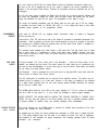
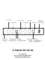
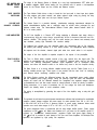
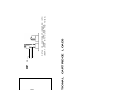
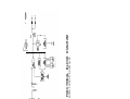
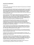
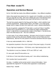
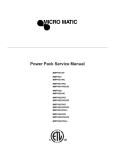
Haflee
H O M E
A U D I O
C O M P O N E N T S
Series 915 Preamp
Series 0915
P
R
E
A
M
P
L
I
F
I
E
R
NOTICE - IMPORTANT SAFETY INFORMATION
RISK OF ELECTRIC SHOCK
00 NOT OPEN
WARNING: TO PREVENT FIRE OR
SHOCK HAZARD, DO NOT EXPOSE THIS
EQUIPMENT TO RAIN OR MOISTURE.
1.
A
I
0
A
The lightning flash with arrowhead symbol within
an equilateral triangle is intended to alert the
user to the presence of uninsulated “dangerous
voltage” within the product’s enclosure, that may
be of sufficient magnitude to constitute a risk of
electric shock to persons.
The exclamation point within an equilateral
triangle is intended to alert the user of the
presence of important operating and maintenance (servicing) instructions in the literature
accompanying the appliance.
READ INSTRUCTIONS
All the safety and operating instructions of your Hafler equipment should be read before power is applied to the
equipment.
2.
RETAIN OWNERS MANUAL
These safety and operating instructions should be retained for future reference.
3.
HEED WARNINGS
All warnings on the equipment and in the operating instructions are important and should be followed.
4.
FOLLOW INSTRUCTIONS
All operating and use instructions are important and should be followed.
5.
HEAT
The equipment should be kept away from areas of high temperature, such as heater vents, radiators, stoves/ovens,
fireplaces, etc.
6.
VENTILATION
The equipment should be used in an area suitable for proper ventilation. Care should be taken not to impede airflow
in and around the cabinet. Do not mount on a carpeted shelf or in a sealed enclosure. Allow for proper clearance above
the equipment.
7.
WATER AND MOISTURE
The equipment should not be used in or around water, such as a bathtub, sink, or swimming area. Also, the equipment
should not be used in areas prone to flooding, such as a basement.
8.
POWER SOURCES
The equipment should be connected only to a power source of the same voltage and frequency as that listed on the
rear panel above the power cord entry point.
9.
POWER CORD PROTECTION
Power cords should be arranged so that they do not interfere with the movement of objects in the room: people, fan
blades, utility carts, etc. Also, care should be taken that the cord is not pinched or cut, and placed so that it is not in
danger of being pinched or cut, as in under a rug, around a tight corner, etc.
10. POWER CORD GROUNDING
The power supply cord is of a three wire grounded type, designed to reduce the risk of electric shock sustained from
a live cabinet. It is assumed to be of suitable length for most uses of the equipment. The use of extension cords and
power strips is discouraged unless they are of suitable rating to deliver the required total current for safe operation of
all connected equipment. Furthermore, extension cords or power strips must provide the same three wire grounded
connection. It is important that the blades of the equipment’s plug be able to fully insert into the mating receptacle.
Never remove the round grounding pin on the plug in an attempt to mate to a two wire ungrounded receptacle: use
a grounding adaptor with the grounding tab or wire suitably connected to earth ground.
-l-
11. NON-USE PERIODS
During periods of extended non-use, the power cord should be unplugged from the power source.
12. CLEANING
The equipment should be cleaned only as detailed in the operating instructions.
13. OBJECT AND LIQUID ENTRY
Care should be taken so that objects and/or liquids, such as cleaning fluids or beverages, are not spilled into the
enclosure of the equipment.
14. DAMAGE REQUIRING SERVICE
Hafler equipment should be serviced by qualified service personnel when:
A.
The power supply cord or plug has been damaged, or
B.
Objects have fallen, or liquid has been spilled into the equipment, or
C.
The equipment has been exposed to rain, or
D.
The equipment does not appear to operate normally or exhibits a marked change in performance, or
E.
The equipment has been dropped, or the enclosure has been damaged.
15. SERVICING
The user should not attempt to service the equipment beyond that which is described in the operating instructions. All
other service should be referred to qualified service personnel.
16. CARTS AND STANDS
The equipment should be used with carts or stands only of sufficient strength and stability for the use intended.
An equipment and cart combination should be moved with care. Quick stops and starts, excessive force, and
uneven surfaces may cause the equipment and cart combination to topple.
-2-
TABLE OF CONTENTS
PERFORMANCE SPECIFICATIONS ............................................................................................
General Information ...............................................................................................................
4
5
INSTALLATION
Rackmounting ........................................................................................................................
Ventilation/Placement ............................................................................................................
Line Voltage ...........................................................................................................................
5
5
5
OPERATION/CONNECTIONS
Power Cord Connection ........................................................................................................
Initial Power-Up/Muting System ............................................................................................
Convenience Outlets .............................................................................................................
Line Level Inputs ...................................................................................................................
Phono Section .......................................................................................................................
Front Panel View Diagram .....................................................................................................
Rear Panel View Diagram .....................................................................................................
Tape Input/Record Output .....................................................................................................
Tone Controls/Tone Switch ...................................................................................................
Volume Control ......................................................................................................................
Balance Control .....................................................................................................................
Out 1, Out 2, And Output Switch .........................................................................................
Headphone Output ..............................................................................................................
5
5
6
6
6
7
8
9
9
9
9
10
10
CIRCUIT DESCRIPTION
Phono Section ......................................................................................................................
Line Level Inpu? Selector System .........................................................................................
10
10
J-FET Buffer And Record Output Driver.. ............................................................................
Tape Monitor Switching ........................................................................................................
Volume And Balance Controls.. ............................................................................................
Line Amplifier.. .....................................................................................................................
Tone Control System ............................................................................................................
Muting System .....................................................................................................................
Power Supply .......................................................................................................................
Headphone Amplifier ...........................................................................................................
11
11
11
11
11
11
11
12
ADDITIONAL INFORMATION
Installing Phono Option .......................................................................................................
Phono Board Installation Diagram .......................................................................................
Installing Cartridge Loads ....................................................................................................
Changing Line Voltage Rating .............................................................................................
Cartridge Loads Installation Diagram ..................................................................................
General Troubleshooting Hints ............................................................................................
Ground Loops ......................................................................................................................
Cleaning/Maintenance .........................................................................................................
Functional Block Diagram ....................................................................................................
Main Board Parts List ..........................................................................................................
Main Board Component Layout Diagram ............................................................................
Main Board Circuit Schematic Diagram ...............................................................................
Phono Board Parts List ........................................................................................................
Phono Board Component Layout Diagram ..........................................................................
Phono Board Circuit Schematic Diagram ............................................................................
.12
.13
.14
.14
.15
.16
.17
.17
.18
.19
.20
.21
.22
.23
.24
SERVICE POLICY AND LIMITED WARRANTY .........................................................................
.25
-3-
PERFORMANCE SPECIFICATIONS
All specifications are for 20 Hz - 20 kHz unless specified otherwise.
PHONO
SECTION
(Measured At
REC OUT)
FREQUENCY RESPONSE: +/-0.1 dB
MAXIMUM OUTPUT: 5 volts RMS
TOTAL HARMONIC DISTORTION AND NOISE:
Moving Magnet: .002%
Moving Coil: .009%
SENSITIVITY (For 0.5 volts RMS at REC OUT, @ 1 kHz):
Moving Magnet: 6.0 mV RMS
Moving Coil: 600 uV RMS
SIGNAL TO NOISE RATIO (A-weighted, relative to 0.5 V RMS at REC OUT):
Moving Magnet: -87 dB
Moving Coil: -80 dB
MAXIMUM INPUT SIGNAL (@ 1 kHz):
Moving Magnet: 65 mV RMS
Moving Coil: 6.5 mV RMS
INPUT IMPEDANCE:
Nominal: 47,000 ohms
Moving Magnet: 220 pF as supplied, user adjustable
Moving Coil: 100 ohms as supplied, user adjustable
GAIN (@ 1 kHz):
Moving Magnet: +38.5 dB
Moving Coil: +58.5 dB
LINE
AMPLIFIER
(Measured at
OUT 1 or OUT 2)
FREQUENCY RESPONSE: +/- 0.1 dB (into 33,000 ohms)
BANDWIDTH: 8 Hz - 170 kHz,
-3 dB, into 10k ohm load
MAXIMUM OUTPUT: 6 volts RMS
TOTAL HARMONIC DISTORTION AND NOISE: .008% @ 2 volts RMS
SENSITIVITY (For 0.5 volts RMS Output): 45 mV RMS
SIGNAL TO NOISE RATIO (A-Weighted, relative to 2 volts RMS output): -100 dB
INPUT IMPEDANCE: 20k ohms (including PHONO/AUX1 when phono option not installed)
OUTPUT IMPEDANCE: 316 ohms
TONE CONTROLS>
HEADPHONE
AMPLIFIER
Bass: +/- 16 dB @ 20 Hz, moving inflection, variable turnover
Treble: +/- 14 dB @ 20 kHz, shelving @ 5 kHz, fixed turnover
MAXIMUM OUTPUT: 4 volts RMS into 150 ohm load
OUTPUT IMPEDANCE: 150 ohms
-4-
GENERAL
INFORMATION
j
INPUTS: Tuner, Video, CD, Phono/Aux
1, Aux 2, Tape Monitor
OUTPUTS: Out 1, Out 2, Record Out, Headphone
CONTROLS: input Selector, Volume, Tape Monitor , Tone Control In, Balance, Bass, Treble,
Output Off, Power, Phono MM/MC
INDICATORS: Mute/Standby, Power
CONVENIENCE OUTLETS: 1 Unswitched, 4 Switched (Polarized)
(Convenience Outlets are not included on 200-240 VAC units)
PHYSICAL DIMENSIONS:
17” (W) x 7-5/8” (D) x l-3/4” (H) (excluding feet); Faceplate 17” or 19” (W).
43.2cm (W) x 19.4cm (D) x 4.5cm (H) (excluding feet); Faceplate 43.2cm or 483cm (W).
POWER CONSUMPTION (Excluding Convenience Outlets): 9 watts Max.
AC LINE VOLTAGE OPERATING RANGE: (exceeding lower limit will activate muting circuit;
exceeding upper limit will result in overheating and/or component damage)
100 - 120 Volt 50/80 Hz Models: 85 - 130 volts
200 - 240 Volt 50/80 Hz Models: 170 - 280 volts
INSTALLATION
RACKMOUNTING
The 915 Preamplifier is supplied in either a 17” Black Version, or a 19” Silver Version. The 19
model has rackmounting holes provided for installation in equipment racks. The holes are on
standard EIA spacings.
VENTllATlON/
PLACEMENT
The 915 produces very little heat during operation, and therefore requires no special considerations for ventilation. The preamplifier should be located at least several inches away from
components that contain large power transformers (such as power amplifiers), due to the
possibility of audible hum or buzz from magnetic radiation.
LINE VOLTAGE
The 915 Preamplifier is configurable for either 100 - 120 volt, or 200 - 240 volt operation. This
is accomplished by changing internal jumpers on the printed circuit board. The procedure is
detailed in the section “CHANGING LINE VOLTAGE RATING”. Make sure that the unit is
configured for your local AC line voltage before attempted use. The configuration is labelled
directly above the power cord connector.
OPERATION/CONNECTIONS
POWER CORD
CONNECTION
Units wired for200-240
VACare supplied without power cords. Local agents will supply cords with
male connectors appropriate to the local standard.
Units wired for 100-120 VAC are supplied with a detachable AC power cord. The female
connector plugs into the receptacle provided on the rear panel. This power cord is a standard
IECType
Type320,
320,
3-wire,
gauge assembly. Should replacement ever be necessary, be sure to
IEC
3-wire,
18 18
gauge
replace it with an identical cord.
Never remove the grounding pin from the male end of the cord. In applications where a grounded
wall outlet is not available, a ground adaptor should be employed, with the ground tab or wire of
the adaptor connected to a suitable earth ground.
INITIAL POWERUP/MUTING
SYSTEM
For units wired for 200-240 VAC, the front panel Power Switch controls the power to the
Preamplifier’s
circuitry. If desired, this switch may be left “on” at all times to allow circuits to be
thermally stabilized for maximum fidelity as soon as the system is used.
-5-
For units wired for 100-120 VAC, the Power Switch controls the Switched Convenience Outlets only.
As soon as the 915 is plugged into the AC line, power is applied to the circuitry (regardless of the
position of the front panel Power Switch). Therefore, all connections should be performed with the unit
unplugged.
For all units, when power is applied, the Ready Light will glow red for several seconds, indicating that
the Audio and Headphone Outputs are muted. Once the delay period has passed and the power
supply has stabilized, the light will turn green. The preamplifier is now ready to enjoy.
The muting will reactivate immediately (and the Ready Light turn red) upon loss of AC line voltage,
(or operating the Power Switch on 200-240 VAC units), or if line voltage falls below a level which
precludes proper operation of the preamplifier’s circuitry.
CONVENIENCE
OUTLETS
Units wired for 200-240 VAC are supplied without convenience outlets to conform to Regulatory
Safety requirements.
Units wired for 700- 720 VAC have a total of five outlets for connection of associated components. The
Unswitched Outlet is powered at all times, which should generally be used for a turntable or tape deck.
The remaining four Switched Outlets are powered when the front panel Power Switch is engaged, as
indicated by the switch’s green pilot light.
The maximum power available from these outlets is 1200 watts total. This total power may be drawn
from a single outlet, or a combination of outlets. Since some power amplifiers consume more than
1200 watts at maximum output, check the power amplifier’s rating before connecting to these
convenience outlets.
LINE LEVEL
INPUTS
The inputs labelled CD, Tuner, Video, Aux 2, and Phono/Aux 1 (when the Phono Option is not
installed), are identical line level inputs. The names chosen for these inputs are for convenience only,
and may be used interchangeably, or for any other type of line level source. These inputs are selected
via the rotary front panel Selector Switch.
The Phono/Aux 1 input is converted from a line level input to a high gain RIAA phono input when the
Phono Option is installed. See Phono Section.
The 915 Preamplifier is available with an optional Phono Amplifier section. This option may be
installed at time of purchase, or at a later date. Inclusion of this option is indicated by the presence
of a switch button protruding from the rear panel opening marked MC/MM. Otherwise, this opening
will be filled by a plastic cover.
The MC/MM switch should be set to MC for low output (typically 0.2 - 0.5 mV) moving coil cartridges,
and set to MM for high output (2 - 5 mV) moving coil cartridges or moving magnet cartridges.
NEVER OPERATE THE MC/MM SWITCH UNLESS THE VOLUME CONTROL IS TURNED FULLY
DOWN. The very high gain present in the Phono Amplifier can result in switching transients capable
of blowing amplifier or speaker fuses, and possibly damaging some loudspeakers.
PHONO SECTION
(When Installed)
The ground terminal near the MC/MM switch is provided for turntable frame grounding via the extra
ground wire provided on most turntables.
As supplied from the factory, the phono cartridge input termination is 47,000 ohms in parallel with 220
pF in the Moving Magnet mode, and 100 ohms in the Moving Coil mode. The value of capacitance
and resistance is user selectable via plug-in components. See “Installing Cartridge Loads” for further
information and instructions.
-6-
INPUT
SELECTOR
BALANCE
VOLUME CONTROL
I
-l
I
CONTROL
TREBLE
CONTROL
BASS CONTROL
HEADPHONE
JACK
POWER SWITCH
UP TO TURN ON
SWITCHED OUTLETS*
0
0
w
.
RACKMOUNT HOLES
(19” VERSION ONLY)
TAPE MONITOR SWITCH
UP TO MONITOR TAPE INPUT
TONE IN SWITCH
UP TO ACTIVATE BASS & TREBLE
OUTPUT OFF SWITCH
UP TO TURN OFF
OUT1 &OUT2
915 PREAMPLIFIER FRONT PANEL VIEW
*lOO-120 VAC UNITS ONLY.
200-240 VAC UNITS ARE WITHOUT CONVENIENCE OUTLETS:
POWER SWITCH CONTROLS PREAMPLIFIER POWER.
A
CJ
READY LIGHT
RED FOR MUTE ACTIVATED
GREEN FOR OPERATE
0
UNSWITCHED
LINE VOLTAGE
RATING
LINE CORD CONNECTOR
AC
SWITCHED OUTLETS
OUT 1
TAPE
AUX 2
TUNER
INPUTS
VIDEO
TOP ROW - RIGHT CHANNEL
BOTTOM ROW - LEFT CHANNEL
OUTPUTS
REC OUT
OUT 2
CD
200-240 VAC UNITS ARE WITHOUT CONVENIENCE OUTLETS.
*100-l 20 VAC UNITS ONLY.
PHONO CHASSIS
GROUND
MC/MM SWITCH
(PHONO OPTION ONLY)
IN-MOVING COIL
OUT - MOVING MAGNET
PHONO/AUX 1
915 PREAMPLIFIER REAR PANEL VIEW
OUTLET*
TAPE INPUT/
RECORD OUTPUT
The 915 incorporates one monitoring loop for use with tape decks, or other input/output signal
processors.
The Ret Out jack feeds a signal to a tape recorder’s input. The signal present at this output is
the same as indicated by the Selector Switch. This output may alternately be used to feed the
input of a signal processing device, such as an equalizer.
Though rare, it is possible that some external devices connected to Rec Out may cause slight
distortion to the main signal path when that device is turned off. This is due to possible
semiconductor junction rectification in unpowered circuits. If this is suspected, leave power
applied to any device connected to Rec Out during critical listening.
The Tape Input is electrically the same as the other line level inputs, but is selected via the Tape
Monitor Switch. Activating this switch (UP position) breaks the main signal path after the Input
Selector System and allows monitoring of the tape decks output, during recording or playback.
Activating this switch does not affect the signal at the Rec Out jacks.
The Tape Input may alternately be used for the return signal from a signal processing device, such
as an equalizer. The Tape Input may also be used for an additional line level input, although this
signal cannot be made available to the Rec Out jacks.
A common system “malfunction” can often be traced to inadvertently leaving the Tape Monitor
Switch engaged: in case of no sound from a selected line level input, check that the Tape Monitor
Switch is de-activated (DOWN position).
See the Functional Block Diagram for a better understanding of the Tape Monitor Signal routing.
TONE CONTROLS/
TONE SWITCH
The Tone In Switch activates the Bass and Treble Controls when moved to the UP position. I n
the DOWN position, the Tone Controls are completely removed from the signal path, regardless
of Bass and Treble knob position.
The Bass Control has a variable inflection, or “hinge” point so that only the very low frequencies
are affected by small amounts of knob rotation on either side of center. This facilitates small
amounts of low frequency corrections without noticeably altering the musical balance at upper
bass frequencies. As the knob rotation is increased further from center, frequencies closer to 500
Hz are affected.
The Treble Control has a fixed “hinge” point at 1 kHz and has a “shelving” action above 5 kHz.
This affords proper high frequency corrections without irritation from excessive boost at extreme
high frequencies.
Activating the Tone Control Switch may cause a slight change in tonal balance even when both
Bass and Treble controls are in their center detented position, and therefore the Tone System
should be disabled via the switch when no tone control action is desired. The tone controls also
limit the total bandpass of the line amplifier.
VOLUME
CONTROL
This precision detented potentiometer increases output level in approximately 1 dB steps
clockwise from the 12 o’clock position. Counterclockwise from the 12 o’clock position, each step
is progressively greater until full attenuation is achieved at maximum counterclockwise position.
This arrangement allows the most natural and useful volume control action for a wide variety of
listening levels.
BALANCE
CONTROL
This control alters the proportion between right and left output volumes. In the full counterclockwise
position, only the left channel will be heard. In the full clockwise position, only the right channel
will be heard. The Balance Control is useful for balancing the acoustic output of the system
between left and right speakers, as well as being useful for system troubleshooting.
-9-
OUT 1, OUT 2
AND OUTPUT OFF
SWITCH
Activating this switch (UP position) turns off both Out 1 and Out 2. It does not affect the headphone
output. This control is useful for turning off the signal to the power amplifier(s) during headphone
listening, or for general system muting purposes.
When activated, the output switch disconnects the line amplifier from the output jacks, and grounds
the jacks to prevent possible system noise due to open amplifier inputs.
Out 1 and Out 2 are connected in parallel, to provide two equal outputs to amplifiers. This feature is
useful for bi-amplified speaker systems, or for running two amplifier/speaker systems.
A common system “malfunction” can often be traced to inadvertently leaving the Output Off Switch
engaged. In case of no sound from the speakers, check that the Output Switch is de-activated (DOWN
position).
HEADPHONE
OUTPUT
The headphone receptacle is a standard 1/4” stereo phone jack, with the tip of the plug as the left
channel, the ring the right channel, and the barrel ground.
The headphone driver circuit is separate from the main line amplifier, and therefore, driving
headphones will not cause distortion on the main outputs.
Unless simultaneously operating loudspeakers during headphone use, the Output Off Switch should
be used to disable the outputs. Remember to reduce the Volume Control setting before turning on the
outputs again, since a normal listening level for headphones may correspond to a surprisingly high
volume for loudspeakers.
CIRCUIT DESCRIPTION
PHONO SECTION
(When Installed)
Each Phono channel consists of six low-noise JFET's connected in a complementary-symmetry, nondifferential configuration. Shorted-input moving coil equivalent-input noise measures about -137 dB
(140 nV) wide band.
Only two stages are used to yield an open-RIAA-loop gain of about 110 dB in moving coil mode and
90 dB in moving magnet mode. RIAA loop closure yields 58.5 dB and 38.5 dB respectively, at 1 kHz.
The first stage employs an active load technique in which the load JFET’s are connected as gyrators,
acting as if they were very large inductors. This arrangement allows very high gain at low frequencies
and a natural roll-off of high frequencies in the amplifier loop, before the RIAA negative feedback loop
is closed.
DC operating point stability is obtained by long time constant DC negative feedback applied from
output to intermediate points in the gain structure.
AC gain is set by the RIAA network feeding back output signals to the sources of the input JFET pair.
Switching to moving coil (MC) from moving magnet (MM) results in three operational changes: 1)
open-loop gain is increased by 20 dB, 2) closed-loop gain is increased by 20 dB, and 3) user adjustable
cartridge loading is changed from capacitive to resistive.
The phono outputs are capacitively connected to the high level Input Selector System.
INPUT
LINE LEVEL
SELECTOR
SYSTEM
The front panel rotary input Selector Switch creates digital codes fed to a CMOS-FET electronic
switch. This arrangement eliminates signal degradation due to mechanical switch contacts, and
allows the electronic switches to be located close to the rear panel inputs for minimum signal path
lengths and reduced interchannel crosstalk. The output of the Selector System is grounded between
positions of the rotary knob to minimize switching noise.
-lO-
JFET BUFFER AND
RECORD OUTPUT
DRIVER
The output of the Selector System is followed by a very high input-impedance JFET buffer pair
to establish negligible CMOS switch loading (for low distortion) and to provide a low-impedance
source for the Record Output and the Volume and Balance controls.
TAPE MONITOR
SWITCHING
The Tape Monitor Switch drives a relay to break the line input path to insert tape input signals.
The relay employs gold plated contacts, and allows optimum signal routing by placing the relay
close to the Tape Input jacks and the Input Selector System.
VOLUME AND
BALANCE CONTROLS
The Volume Control is a precision detented potentiometer employing laser-trimmed elements for
precise channel-balance tracking and a multi-finger wiper for smooth action, prolonged life, and
minimum contact noise. The center-detented Balance Control yields channel balance within 0.1
dB in its center position.
LINE AMPLIFIER
The 915 Line Amplifier is a Class-A JFET design employing a differential input stage, driving a
complementary high gain output stage, symmetrically driven for balanced slew-rate and low
harmonic distortion. This topology uses only four active devices per channel and extremely short
loop feedback, yielding high bandwidth and excellent stability.
The feedback loop contains two user selectable paths: one conventional path for flat response,
and another path allowing insertion of a tone control network. This arrangement allows maximally
flat response and the shortest, cleanest signal path when tone control action is not required.
The output of the Line Amplifier is capacitor coupled to the outputs of the preamplifier.
TONE CONTROL
SYSTEM
The Tone In Switch allows complete removal of the tone controls from the signal path. This
switching is accomplished with the same type of CMOS-FET electronic switch used for the Input
Selector. This switching arrangement eliminates signal degradation due to mechanical switch
contacts, and allows the electronic switch to be located very close to the Line Amplifier circuitry.
The Bass Control is of a moving inflection, variable turnover type, and the Treble Control is of a
shelving, variable turnover type. These types of tone controls offer the best “tools” for modifying
tonal balance without introducing unwanted side effects.
MUTING
SYSTEM
The Muting System monitors the difference between the raw (unregulated) power supply voltage
and the regulated power supply voltage. During the power-up cycle, the Audio and Headphone
Outputs are muted until the difference between the unregulated and regulated voltages reaches
a predetermined level, and then remain muted for several seconds to allow all circuitry to stabilize.
During power-down, or in cases of excessively low AC line voltage, the Audio and Headphone
Outputs are instantly muted to avoid extraneous noises.
The muting is accomplished by grounding the output of the Line Amplifier, using a relay with gold
contacts.
POWER SUPPLY
The printed circuit board mounted power transformer utilizes dual primaries for worldwide
operation. Internal jumpers configure the power supply for rated operation from 100 to 120 VAC,
or 200 to 240 VAC, at 50 or 60 Hz. A generous amount of power supply headroom allows actual
operation over much wider ranges of 85 to 130 VAC, or 170 to 260 VAC.
The power transformer feeds a conventional split full wave bridge rectifier system. Power supply
capacitance is 4700 pF per rail. Stable and consistent ± l5 volt power for the amplifier circuits is
provided by three-terminal heatsink-mounted regulators. Further local power supply filtering of
470 UF per rail is provided for each channel of the Line and Phono Amplifiers. All electrolytic filter
capacitors are bypassed by high quality film capacitors.
-ll-
Internal signal grounding has been carefully routed to follow the signal path from the input jacks,
through the Selector System, through the Volume and Balance Controls, and finally to the line
amplifier. All power supply ground paths are returned to a single “star” ground point at the power
supply to minimize ground modulations. Extensive use of ground planes and interchannel shields
maximize inter-channel separation.
For units wired for 100-120
VAC, the power supply is kept “on” at all times so that all circuitry is
maintained at optimum operating temperature, for maximum fidelity as soon as the system is used.
The front panel Power Switch operates the Switched Outlets only, to turn on associated system
components.
For units wired for 200-240
VAC, the Power Switch controls the preamplifier’s power supply. This
switch may be left “on” at all times, if desired, to maintain optimum operating temperature.
HEADPHONE
AMPLIFIER
The Headphone Amplifier utilizes a separate high-slew rate operational amplifier to drive the high
current demands of headphone operation. This relieves the Line Amplifier from the additional burden
of driving difficult headphone loads, and leaves the main signal path uncompromised for signals to
power amplifiers.
The Output Off Switch turns off both line outputs, to be used when listening to headphones only, or
as a system muting switch.
ADDITIONAL INFORMATION
INSTALLING
PHONO OPTION
If the 915 Preamplifier was purchased without the Phono Option, the Phono/Aux 1 input is a line level
input, and cannot be used with a turntable. To convert this input for use with a turntable, purchase
the 915 Phono Option Accessory from your Hafler Dealer. Review the installation instructions before
attempting this procedure. If any doubts exist about one’s ability to install the Phono Option, it is
advisable that the procedure be conducted by a qualified technician.
WARNING! UNPLUG THE UNIT FROM AC POWER BEFORE ATTEMPTING THIS PROCEDURE.
FAILURE TO DO SO CAN RESULT IN SEVERE ELECTRICAL SHOCK AS WELL AS DAMAGE TO
THE PREAMPLIFIER AND/OR PHONO BOARD.
1)
Place the preamplifier on a soft, protective surface. Remove the eight allen head screws (four
on each side), and six phillips head screws (three each on top and bottom), securing the top and
bottom covers. Remove covers. Carefully remove the plastic plug covering the MC/MM switch
hole by squeezing the prongs inside the chassis and prying out the plug.
2)
Find the three wire jumpers on the main printed circuit board, located near the Phono/Aux input
jacks, labelled RJ5, RJ7, and RJ8. Remove the three jumper wires as shown. These jumpers
may be de-soldered or clipped out.
3)
Refer to the diagram “Installation Of Optional Phono Printed Circuit Board”. Push the MC/MM
switch to the “in” position to ease installation of the phono board. Carefully guide the phono board
onto the main board, checking to make sure that all the electrical connector pins are aligned with
their mating parts before completely seating the phono board onto the three plastic standoffs.
It should snap into place with no free play. Double check that all four pins of each of three
connectors have been inserted completely.
If some of the pins have not properly seated, squeeze the prongs of the three plastic standoffs to release the phono board. Straighten any bent pins before re-attempting installation.
4)
Add the button to the shaft of the MC/MM switch. Unless modifying the cartridge loads at this
time, replace the covers. (See Installing Cartridge Loads).
-12-
MAIN PC BOARD
PHONO PC BOARD
-T
INSTALLATION OF OPTIONAL PHONO PRINTED CIRCUIT BOARD
PLASTIC STANDOFFS
4 PIN CONNECTORS
PLASTIC BUTTON
INSTALLING
CARTRIDGE LOADS
Optional cartridge loading is a “fine tuning” matter. Many cartridges are not sensitive to loading
and work well without it. Only a cartridge’s manufacturer can provide recommended loading, as
every cartridge is different. And only the user can say for sure whether or not it produces
meaningful sonic improvement.
Components suitable for cartridge loads may be obtained from electronic parts or specialty audio
Capacitors
component suppliers. Resistors
Resistors should be 1% tolerance, metal-film, l/4 watt types. Capacitors
should be axial lead, 10% (or better) tolerance, miniature polypropylene or polystyrene types.
As supplied from the factory, the 915 Preamplifier has been fitted with 100
100 ohm
ohm resistors
resistors and 220
220
pF capacitors installed in the appropriate sockets. While these values are suitable for most
cartridges, the procedure described below may be used to alter these values. Review the
installation instructions before attempting this procedure. If any doubts exist about one’s ability
to install the cartridge loads, it is advisable that the procedure be conducted by a qualified
technician.
WARNING! UNPLUG THE UNIT FROM AC POWER BEFORE ATTEMPTING THIS PROCEDURE. FAILURE TO DO SO CAN RESULT IN SEVERE ELECTRICAL SHOCK AS WELL AS
DAMAGE TO THE PREAMPLIFIER AND/OR PHONO BOARD.
1)
Place the preamplifier on a soft, protective surface. Remove the four allen head screws (two
on each side), and three phillips head screws, securing the bottom cover. Remove cover.
2)
Refer to the diagram “Installation Of Optional Cartridge Loads” for the location of the
appropriate sockets, and how to form the component leads. Make sure that the component
leads are only long enough to securely mate to the sockets. Be sure not to stress the
component lead where it enters the body of the part. Observe carefully which sockets are
for MM (capacitors) and for MC (resistors).
3) Replace cover.
NOTE: Even while experimenting with different optional loads, the cover must be replaced before
re-applying AC power, not only for safety reasons, but to shield hum and interference which can
totally invalidate any attempts at sonic evaluation.
CAUTION: When low value resistors are installed and selected by the MC switch position,
accidentally using this setup for a high output moving coil cartridge can result in deceptively normal
output levels, but with improper cartridge frequency response.
CHANGING UNE
VOLTAGE RATlNG
The 915 Preamplifier can be internally wired for two different AC line voltage ranges: 100 - 120
VAC, or 200 - 240 VAC, 50/60 Hz. The configuration is labelled above the power cord connector.
If the preamplifier will be used in a location that requires a different line voltage, it is possible to
change the configuration. Review the modification instructions before attempting this procedure.
If any doubts exist about one’s ability to change the line voltage, it is advisable that the procedure
be conducted by a qualified technician.
NOTE: As supplied from the factory, units wired for 100-l 20 VAC have five Convenience Outlets,
and the Power Switch controls the Switched Convenience Outlets only. (Power is applied to the
preamplifier’s circuitry as soon as the unit is plugged in.) For units factory wired for 200-240 VAC,
no Convenience Outlets are supplied, and the Power Switch controls application of power to the
preamplifier’s
circuitry. Note that changing the Line Voltage affects only the operating line voltage:
the above described switching arrangements will remain the same.
WARNING! UNPLUG THE UNIT FROM AC POWER BEFORE ATTEMPTING THIS PROCEDURE. FAILURE TO DO SO CAN RESULT IN SEVERE ELECTRICAL SHOCK.
-14-
1
3181'
MAX.
DETAIL OF COMPONENT INSERTION INTO
PHONO LOAD SOCKETS
(INSERT LEADS INTO OUTER TWO HOLES)
INSTALLATION OF OPTIONAL CARTRIDGE LOADS
PHONO BOARD -
MOVING COIL LOADS
(RESISTORS)
MOVING MAGNET LOADS
(CAPACITORS) \
Place the preamplifier on a soft, protective surface. Remove the eight allen head screws (four
on each side), and six phillips head screws (three each on top and bottom), securing the top and
bottom covers. Remove covers.
2)
Referring to the diagram “Main Printed Circuit Board Component Layout”, locate the three wire
jumper locations labelled “A”, “B”, and "C", in front of the power transformer. These jumpers
control the series/parallel connections of the power transformer’s primary.
3)
Remove the old jumper(s) by desoldering and replace with new jumper(s) as indicated:
100 - 120 VAC: Jumpers A & B installed
200 - 240 VAC: Jumper C installed
Be sure to clip off excess wire length on the solder (non-component) side of the printed circuit
board.
4)
Referring again to the diagram, locate the clip-mounted fuse. Replace this fuse with a new slowblow fuse as indicated:
100 - 120 VAC: 1/10 AMP
200 - 240 VAC: 1 /16 AMP
5)
Referring again to the diagram, locate the wire jumper location labelled “Remove For 240
VAC”, behind the transformer. This jumper controls the voltage supplied to the Power Switch
indicator lamp. Remove or install this jumper as indicated:
100 - 120 VAC: Jumper Installed
200 - 240 VAC: Jumper Removed
GENERAL
TROUBLESHOOTING
HINTS
6)
Replace the covers.
7)
Obtain a new voltage configuration label from the factory, and affix over the original markings.
Alternately, prepare a small self adhesive label and indicate the new voltage range with
permanent ink. Relabelling the unit is a vital safety requirement, particularly if the preamplifier
is sold to a new owner.
The 915 Preamplifier is configured for normal operation when all toggle switches are in the “down”
position. That is, Tape Monitor is NOT selected, Tone Controls are OFF, and the outputs are ON. If
no sound is heard from the system, first check the position of the Tape Monitor and Output switches.
If altered tonal balance is detected (even with the Bass and Treble controls centered), check the
position of the Tone switch.
If the Ready light is off or glowing red, the preamplifier’s outputs are muted and no sound will be heard.
If rated AC power is present and the light is glowing red, then the delay circuit will un-mute the outputs
within several seconds. If the delay circuit does not un-mute within a few seconds and the light
continues to glow red, check for low AC line voltage, and that the unit is configured for the local line
voltage. If the Ready light is off, check the AC power connections.
If all controls are in the intended position and the Ready light is green, check all system power
connections, interconnecting and speaker cables, and fuses. The 915 does contain one internal
power fuse, but this fuse should not generally blow unless a malfunction has occurred. This fuse
should be replaced only with the exact type and rating of fuse originally supplied. If this fuse is replaced
and blows again within a short time, disconnect all power immediately and return for service.
If all controls, fuses, cables, etc. seem to be functioning properly, a process of one-at-a-time
component substitution should be employed until the defective unit is identified. If only one channel
is not functioning properly, a one-at-a-time reversal of interconnect and speaker cables from left to
right should reveal the malfunctioning component.
-16-
GROUND LOOPS
Ground loops are characterized by a low level hum or buzz in the system. Loops are caused by
a voltage potential difference between two points in a ground circuit, and aggravated when multiple
paths for a given circuit exist. Noise-free audio performance is dependent upon all grounds being
at the same potential, with a single path for each ground connection. Ground loops can exist in
two forms: 1) loops created in audio interconnects, and 2) loops created between earth grounded
chassis.
Mounting components to a rack with metallic rails may introduce ground loops between associated
equipment, because the rails can introduce a second ground path. The extent of this problem will
depend on the grounding arrangements of associated equipment. Ground loops can occur in nonrackmounted equipment, though it is less common.
If ground loops occur, and any other component in the system has a three wire grounded power
cord, the first step should be to use a ground adaptor (with the ground tab or wire of the adaptor
not connected) on the power cord plug of the preamplifier. DO NOT cut off the grounding pin on
the plug! It may be necessary to use additional adaptors on other grounded components if more
than two components are earth grounded. (In other words, only one earth ground per system
should exist.) Another potential source of multiple earth grounds is from coaxial antenna or cable
service feeds for FM or video sources, which usually are (and should be) earth grounded. The
ground adaptor(s) should cure this grounding problem as well.
WARNING: The use of ground adaptors (with the ground tab or wire of the adaptor
disconnected) will eliminate the safety feature of the grounded power cord. This safety
feature is intended to reduce the risk of electric shock should an internal fault in the
equipment result in an electrically “live” chassis. Therefore, this method of ground
isolation should be employed only when absolutely necessary, rather than as a general
practice. When using a ground adaptor for isolation, make sure that the power cord plug
is inserted into the receptacle in the same orientation as if no adaptor were present, to
maintain the same hot/neutral polarity.
SPECIAL NOTE ON VIDEO CABLE “GROUNDS”: As mentioned above, the ground conductor
of cable service and antenna feeds should be connected to earth ground. Often, however, due
to long feed lengths, especially in apartment distribution systems, this ground will be of poor quality
and could be a source of noise. This interference is usually characterized by a high frequency
noise, rather than a hum or a buzz. If such interference is experienced, a separate earth ground
connection should be made from the cable outlet nearest the audio/video equipment to a known
good earth ground.
If ground loops exist due to potential differences in the interconnects in rack mounted systems,
then it is advisable to isolate the preamplifier chassis from the rack rails. This may be
accomplished by sandwiching a thin sheet of insulating material (i.e., plastic washers or several
layers of electrical tape, etc.) between the rack and the preamplifier, and securing the unit with nonmetallic (i.e., nylon, etc.) hardware. It may be necessary to insulate other components so that only
one component is directly connected to the rack rails.
CLEANING/
MAINTENANCE
If the faceplate should become soiled, it may be cleaned with a slightly damp, soft cloth, and, if
necessary, a mild detergent. Do not use any abrasive cleaners or solvents. Unplug the power cord
before attempting any cleaning operations.
Except as specifically detailed in the owners manual, there are no user serviceable parts or
adjustments inside the 915 Preamplifier, and all servicing should be referred to qualified,
authorized personnel. The only user access to the inside of the chassis should be for changing
the optional loading for the phono inputs (when installed). See “Phono Section”.
-17-
I
t
I
ONE CHANNEL SHOWN, PHONO OPTION INSTALLED
915 PREAMPLIFIER FUNCTIONAL BLOCK DIAGRAM
PARTS LIST - MAIN CIRCUIT BOARD
DESIGNATORS l-99: FOR COMMON AND RIGHT CHANNEL PARTS 100-199: FOR LEFT CHANNEL
DESIGNATOR
PART NUMBER
VALUE
ALL RESISTORS 1/4 WATT, 1% METAL FILM
R1, R101
2.15K
R2, R102
20K
R3
100K
R4
100K
R5
100K
R6, R106
20K
R7, R107
1K
R8, R106
1K
R9, R109
33.2
R10, R110
33.2
R11, R111
20K
R12
221
R13, R113
20K
100K
R14
R15, R115
182K
100K
R16, R116
R17, R117
150
274K
R16, R116
R19
10K
162K
R20
100K
R21
100K
R22
4.75K
R23
47.5K
R24
1.5K
R25
2.21K
R26
150K
R27
1K
R26
499
R29, R129
11K
R30, R130
1.1K
R31, R131
11K
R32, R132
11K
R33, R133
11K
R34, R134
1.1K
R35, R135
1.1K
R36, R136
R37, R137
316
R36, R136
316
R39, R139
20K
R40, R140
316
R41, R141
100
100
R42, R142
4.99K
R43, R143
10K
R44, R144
4.7M
R45, R145
20K
R46, R146
1 .0M
R47. R147
R46, R146
100
R49, R149
100
100K
R50, R150
R51, R151
316
10K
R52
10K
R53
RMP/4-2151
RMP/4-2002
RMP/4-1003
RMP/4-1003
RMP/4-1003
RMP/4-2002
RMP/4-1001
RMP/4-1001
RMP/4-0332
RMP/4-0332
RMP/4-2092
RMP/4-2210
RMP/4-2002
RMP/4-1003
RMP/4-1623
RMP/4-1003
RMP/4-1500
RMP/4-2743
RMP/4-1002
RMP/4-1623
RMP/4-1003
RMP/4-1003
RMP/4-4751
RMP/4-4752
RMP/4-1501
RMP/4-2211
RMP/4-1503
RMP/4-1001
RMP14-4990
RMP/4-1102
RMP/4-1101
RMP/4-1102
RMP/4-1102
RMP/4-1102
RMP/4-1101
RMP/4-1101
RMP/4-3160
RMP/l4-3160
RMP/4-2002
RMP/4-3160
RMP/4-1000
RMP/4-1000
RMP/4-4991
RMP/4-1002
RMP/4-4754
RMP/4-2002
RMP/4-1004
RMP/4-1000
RMP/4-1000
RMP/4-1003
RMP/4-3160
RMP/4-1002
RMP/4-1002
DIODES
D1
D2
D3
D4
D5
D6
D7
D6
D9
D10
D11
D12
D13
D14
D15
SS-161
SSH-652
SSH-652
SS-161
ss-171
SS-162
SSH-653
SS-161
SS-161
SS-162
SS-162
SS-162
SS-162
SS-161
SS-161
1N4003
1N5239B
1N5239B
1N4003
1N4736A
1N4148
1N5226B
1N4003
1N4003
1N4148
1N4148
1N4148
1N4148
1N4003
1N4003
9.1V
9.1V
6.8V
3.3V
DESIGNATOR
VALUE
PART NUMBER
U1 U101
U2
U3
U4
U5
4051
4053
NE5532
7815
7915
SSH-656
SSH-657
SSH-667
SSH-625
SSH-628
Q1,Q101
Q2,Q102
Q3,Q103
Q4,Q104
Q5, Q105
Q6,Q106
Q7
Q8
::0
SW1
SW2
SW3
SW4
2SK163, Graded
2SK163. Graded
2SK163
2SK163
2SK163
2SJ74
BC560C
BC560C
BC560C
BC550C
Rotary Switch
Toggle Switch
Toggle Switch
Power Switch
SW5, SW1 05
Toggle
SSH-614T
SSH-614T
SSH-614
SSH-614
SSH-614
SSH-617D
SSH-651
SSH-651
SSH-651
SSH-650
SWH-153
SWH-151
SWH-151
SWH-152G (Gray)
SWH-152B (Black)
SWH-151
RLY1
RLY2
Relay
Relay
SWH-146
SWH-146
Volume Control
Balance Control
Bass Control
Treble Control
RVH-503C
RVH-104A
RVH-104B
RVH-1048
LED1
Tri-Color
SSH-739
J1-J3
J4
J5-J9
J10
4-Pin Header
IEC Connector
Convenience Outlet
Headphone Jack
CCH-203
CCH-233
CCH-150
CCH-208
F1
F1 (EXPORT)
1110 Amp Slow Fuse
1 /1 6 Amp Slow Fuse
FS-111 OSB
FS-1/16SB
T1
Transformer
l-r-915
BR1
Bridge
ss-222
VR1,
VR2,
VR3,
VR4,
VR101
VR102
VR103
VR104
Switch
LED
Rectifier
All Capacitors In Microfarads Unless Specified Otherwise
4.7 25V Tant.
CTR-475A
C1
CTR-475A
C2
4.7 25V Tant.
.O1 1 KV Ceramic Disc
CD-103/20
C3
C4
0.11 OOV Pofycarbonate
CPC-104
C5
0.11 WV Polycarbonate
CPC-104
4700 35V Electrolytic
C6
CER-478B
C7
4700 35V Electrolytic
CER-478B
C8
.01 Ceramic Disc, UL
CD-103A
C9,C109
.015 160V Polycarbonate
CPC-153
C10, C110
.0015 160V Polypropylene
CPP-152
C11,C111
.47 63V Polycarbonate
CPC-474
C12,C112
.047 63V Polycarbonate
CPC-473
C13,C113
470 Non Polar Electrolytic
CERNP-477
C14,C114
0.1 100V Polypropylene
CPP-104MC
C15
4.7 25V Tant.
CTR-475A
C16. C116
47p Polystyrene
CPS-470
C17
4.7 25V Tant.
CTR-475A
C18, C118
0.1 1 OOV Polypropylene
CPP-104MC
68p Polystyrene
C19, C119
CPS-680
470 25V Electrolytic
C20, C120
CER-477A
470 25V Electrolytic
C21, C121
121
CER-477A
0.1 1 WV Polypropylene
C22, C122
CPP-104MC
0.1 1 OOV Polypropylene
C23, C123
CPP-104MC
2.2 250V Polypropylene
C24, C124
CPP-225MC
.47 63V PoLycarbonate
C25, C125
CPC-474
C26
47 25V Electrolytic
CER-476A
C27
470 25V Electrolytic
CER-477A
C28
470 25V Electrolytic
CER-477A
.01 1KV Ceramic Disc
C29
CD-13/20
0.1 1 OOV Pofycarbonate
CPC-104
-19-
us
1 u 10
-
!!
I
I!
!
!
!
I
I
wvuwla mom lN3NOdW03 awoa mm13 NIVW
‘NOlldO ONOHd LIOA
CY,.tl”P r 21”nqy
I
A&B=100-12OVW:
c - 2 0 0 - 2 4 0 VAE:
rJoba’----- -1
i
+--A-----L’
D7
1 N5226B
Bci
D6
lN4145
PWNOOPllONJUMPERS
PHONOPWER
K
1
4
hL
RlQ
1OK
1
.di
i
+15V
+15V-
-15V
CH
Rl
+15V
L CH
Rlb
274K
JlO
R17
MUTE RUAY
BOARD CIRCUIT SCHEMATIC
ENANCE
UNLESS SPECIFIED OTHERWISE
1. RIGHT CHANNEL ONLY SHOWN
2. COMPONENT
DESIGNATORS
RIGHT CHANNEL
1-99 FOR COMMON AND
PARTS. 100-199 FUR LEFT CHANNEL
5. ML RESISTORS IN OHMS,
CAPACITORS
IN M
C
I ROFARADS
4.TCNE5WllCHSHWNINBYPASSPO5RlCN
5. TAPE MONITOR SWITCH
SHOWN IN WE POSITION
6.MUERW.AY5lUWNINUNMUTEDPDSnlDN
PARTS
PARTS LIST
LIST - PHONO BOARD
DESIGNATORS
1- 99: FOR RIGHT CHANNEL PARTS
100-l 99: FOR LEFT CHANNEL
DESIGNATOR VALUE
PART NUMBER
All Resistors 1/4 Watt, 1% Metal Film
R1, R101
R2, R102
R3, R103
R4, R104
R5, R105
R6, R106
R7, R107
R8, R108
R9, R109
R10, R110
R11, R111
R12, R112
R13, R113
R14. R114
R15, R115
R16, R116
R17, R117
R18, R118
R19, R119
R20, R120
681
33.2 L o w Noise
33.2 L o w Noise
681
26.7K
332K
47.5K
316
100
33.2 L o w Noise
3.32M
1 .OK
22.1M
10M
316
3.32M
1 .OK
22.1M
10M
316
RMP/4-6810
RMP/8-0332LN
RMP/8-0332LN
RMP/4-6810
RMP/4-2672
RMP/4-3323
RMP/4-4752
RMP/4-3160
RMP/4-1000
RMP/8-0332LN
RMP/4-3324
RMP/4-1001
RMP/4-2215
RMP/4-1005
RMP/4-3160
RMP/4-3324
RMP/4-1001
RMP/4-2215
RMP/4-1005
RMP/4-3160
Q1, Q101
Q2, Q102
Q3, Q103
Q4, Q104
Q5, Q105
Q6, Q106
2SK147
2SK147
2SJ72
2SJ72
2SJ74
2SK163
SSH-674
SSH-674
SSH-617C
SSH-617C
SSH-617D
SSH-614
SW1 , SW1 01
4PDT Switch
SWH-125
J1-J3
4-Pin
CCH-240
All
Capacitors
C3
C4
C5, C105
C6, C106
C7, C107
C8, C108
C9, C109
C10, C110
In
Receptacle
Microfarads
Unless
Specified
0.1 1 OOV Polypropylene
0.1 1 OOV Polypropylene
.0027 1% Polystyrene
.01 1% Polystyrene
2.2 Polyester
2.2 Polyester
2.2 250V Polypropylene
220pf Polystrene
Otherwise.
CPP-104MC
CPP-104MC
CPS-272
CPS-103
CP-225
CP-225
CPP-225MC
CPS-221
-22-
l-l
I
I I
1
R3n
RlO 4-k
R 2 -c=l-
a
"R1B05
4
-fxb R 1 0 3 0
RllO <
3 R102 >
D
En
0104
c5 R;' %13
jRSo f;oRll
Rl9
1
R6
R l 1 8 "OS ii:: R l 1 3
Rfli Rl150
Rll9
Rl4
J3
R108
BfWOd'
Rl14
52
4
[I
4
PHONO BOARD COMPONENT LAYOUT DIAGRAM
-23-
PHONO INPUT
R15
316
L CH
I
IMC/MM
SWrrCH
a2
f
D,‘)
I.,#.
Rl
RR1
-.
1Mp
+
=
1 .OK
I
05
2sJ74
J2
RlO
PHONO OUTPUT
II
I,
B
R18
,
22.1M
06
2SK163
-%+
Q
R20
316
PHONO POWER
1. RIGHT CHANNEL ONLY SHOWN.
2. COMPONENT DESIGNATORS 1-99 FOR RIGHT CHANNEL PARTS. 1 W-199 FOR LEFT CHANNEL.
3. ALL RESISTORS IN OHMS, CAPACITORS IN MICROFARADS.
4. MC/MM SWITCH SHOWN IN MOVING MAGNET POSITION.
PHONO BOARD CIRCUIT SCHEMATIC DIAGRAM
SERVICE POLICY AND LIMITED WARRANTY
If you encounter any difficulty or have any question concerning your 915 Preamplifier, please call
our Customer Service Department weekdays, 8 am to 3:30 pm, Mountain Standard Time, at 602967-3565.
Should you have any doubts as to whether the preamplifier is malfunctioning and requires
service, please call us before sending in for repair. All units being returned (regardless of
warranty status) must receive a Return Authorization (RA) number. In addition, we can offer
troubleshooting assistance that may simplify or even eliminate the need for factory service.
The Hafler 915 Preamplifier is warranted to the original owner (non-transferrable) for seven years
from the date of purchase, including parts, labor, and return shipping costs within the Continental
United States. This warranty applies only to products sold in the United States Of America. For
warranties outside the USA, please contact your local agent.
It is the owner’s responsibility to pay shipping (preferably United Parcel Service, UPS) to the
factory: collect shipments will not be accepted. Units under warranty should be accompanied by
a copy of the dated Bill Of Sale. Use the original carton and all packing material, with the RA
number clearly marked on the outside of the package. Be sure to include a return address, the
RA number, a daytime telephone number, and a brief description of the difficulty, including
whether it occurs continuously or intermittently.
This warranty gives you specific legal rights. You may also have other rights which vary from state
to state.
-25-