1
Bulletin 527-G
Installation and Maintenance
Series EHU-700 Humidifiers
Please Read And Save These Instructions
The Armstrong Series EHU-700 humidifier is an electronically controlled, non-pressurized steam-generating
humidifier, with its vapor discharged into a duct of an air-handling system or through a fan package. The
Armstrong Series EHU-700 consists of three models: The EHU-701, 703 and 704. The maximum capacity
of the series is 240 Ibs/hr.
To allow the Series EHU-700 humidifier to function to its full capability, be certain to install it in accordance
with the following Armstrong recommendations. For further assistance, please contact your local Armstrong
representative for the video tape, "Armstrong Series EHU-700 Humidifiers: Installation, Operation and
Maintenance".
DANGER
ELECTRICAL SHOCK HAZARD
HIGH VOLTAGES EXIST INSIDE THE HUMIDIFIER
To protect yourself and others from accidental shocks:
1. Keep the humidifier locked during normal operation and store the key in a safe location away from
the humidifier.
2. ALWAYS DISCONNECT THE POWER SUPPLY AT THE CIRCUIT BREAKER OR SAFETY
SWITCH BEFORE OPENING ANY COVERS!
3. Before servicing the humidifier, learn where the high voltage parts are. KEEP HANDS AND
METAL TOOLS AWAY FROM THESE AREAS!
Figure 2-1
Figure 2-2
2
TABLE OF CONTENTS
SECTION 1: PREPARATION AND INSTALLATION
WARNINGS..................................................................................................................
PRE-INSTALLATION...................................................................................................
Check shipment................................................................................................
Check local codes............................................................................................
Site selection....................................................................................................
INSTALLATION...........................................................................................................
Mounting...........................................................................................................
Electrical wiring................................................................................................
Water supply.....................................................................................................
Drain connection...............................................................................................
Steam dispersion tube......................................................................................
Control wiring....................................................................................................
High limit humidistat.........................................................................................
Airflow switch....................................................................................................
Audible alarm....................................................................................................
Wiring diagram..................................................................................................
SECTION 2: START-UP AND OPERATION
DISPLAY (INSTRUMENT) PANEL...............................................................................
START-UP PROCEDURE..............................................................................................
SECTION 3: TROUBLESHOOTING AND MAINTENANCE
TROUBLESHOOTING GUIDE.....................................................................................
Principle of operation.........................................................................................
Operational guidelines.......................................................................................
Diagnostics.........................................................................................................
WATER QUALITY AND TREATMENT..........................................................................
General..............................................................................................................
Conductivity too low...........................................................................................
Conductivity too high.........................................................................................
MAINTENANCE............................................................................................................
Parts...................................................................................................................
Recommended maintenance.............................................................................
Steam generator maintenance, general............................................................
Tank removal and replacement.........................................................................
Chemical tank cleaning.....................................................................................
Fill and drain valve repair...................................................................................
TANK DISASSEMBLY,
ELECTRODE REPLACEMENT....................................................................................
EHU-703,704.....................................................................................................
EHU-701, single and three phase......................................................................
HUMIDISTAT DATA......................................................................................................
Autocal Procedure.............................................................................................
Sensor Failure Protection..................................................................................
High Limit Humidity Sensor ..............................................................................
Humidity Set Point Reset by Outside Temperature ..........................................
3
2
4
4
4
4
6
6
6
7
7
7
9
11
11
12
12
13
14
17
17
18
20
23
23
23
24
25
25
29
29
30
31
33
33
33
34
36
36
36
38
38
PRE-INSTALLATION
1) CHECK SHIPMENT
A claim should be filed with the transportation company (and reported to Armstrong) if any items
are missing or damaged. Your shipment will arrive in two or three cartons.
One carton holds the humidifier with the steam generator installed, the control humidistat and
sensing element, two short steam hoses, hose clamps, mounting plate and lag screws, and a
clear drain hose. If you have ordered a duct pressure switch or a high limit stat, these too will
be in the humidifier carton.
The steam dispersion tube(s) and fittings are contained in another carton ( two for the EHU 704).
Two complete sets of
installation instructions have
been shipped with your unit.
One is for the installer's use.
The second is for the owner's
files.
Figure 4-1. EHU-701
2) CHECK LOCAL CODES
Series EHU-700 humidifiers
should be installed in
accordance with ALL
applicable building, plumbing,
and electrical codes.
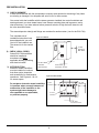
3) SITE SELECTION
Electronic steam humidifiers
must be installed in locations
that allow routine inspection
and accessibility for maintenance
operations. See Figures 4-1 & 4-2
for access space.
4" Side
Clearance
Both Sides
24" Min. Steam
Generator
Tank Removal
Do not place electronic steam humidifers
in locations where unusual instances of
malfunction of the humidifier or the
system might cause damage to
non-repairable or un-replaceable,
or priceless property.
5" Min. Drain
Connection Access
Figure 4-2. EHU-703/704
4" Side
Clearance
24" Side
Clearance
24" Front
Clearance
5" Min. Drain
Connection Access
4
The mounting surface should be a wall capable of supporting the maximum humidifier weight.
The maximum operating weight is:
Model unit
701
703
704
Water
60 Ibs. + 20 Ibs.
83 Ibs. + 30 Ibs.
95 Ibs. + 60 Ibs.
=
=
=
Total
80 Ibs.
113 Ibs.
155 Ibs.
The location chosen should be inside with a minimum ambient temperature of 40°F. and a maximum of
100°F. The humidifier should not be mounted on hot surfaces.
The location should be close enough to the air duct so that the length of steam pipe is as short as
possible. A length of 10 ft. or less is ideal; the maximum recommended length for running distribution
piping is 40 feet of equivalent run. The number of piping elbows in the installation should be minimized
(see Pages 7 and 8 for more information.)
The unit should have ready access to electrical service, a supply of ordinary tap water, and a sewer
into which the drain line can discharge hot waste water. (Figure 5-1)
NOTE: Please contact factory for duct applications offering high static pressure (>4" WC).
Figure 5-1
5
INSTALLATION
4) MOUNTING THE HUMIDIFIER
MODEL EHU-701: Making sure the unit is level, hold it against the mounting surface and mark
the hole pattern. Attach the units to studs or other sturdy structure with the two 3/8"× 1½" lag
screws provided.
MODELS EHU-703 & 704: Making sure the mounting bracket is level, attach it to studs or other
sturdy structure with the two 3/8"× 1½" lag screws provided. Hang the humidifier on the mounting
bracket.
5) ELECTRICAL SERVICE WIRING
Refer to the nameplate on the unit for recommended fuse size. Table 6-1 relates the fuse size to
the appropriate branch size. A complete wiring diagram shown in Figure 12-1 is located inside
the door of the humidifier.
IMPORTANT: Please observe the following:
a. Make certain there is a manually operated interlocking circuit breaker or safety switch (not
furnished) in the electric service ACCESSIBLE TO AND WITHIN SIGHT OF THE
HUMIDIFIER.
b. USE ONLY WIRE WITH COPPER CONDUCTORS RATED 90°C OR HIGHER
FOR HIGH VOLTAGE AND GROUNDING.
c. Pass high voltage ground lead through provided ferrite core (AN) between where it enters
the cabinet and where it connects to ground lug.
d. Ground the humidifier cabinet; a ground lug is provided in the wiring compartment.
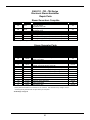
Table 6-1. Series EHU-700 Capacities and Electrical Ratings
Recommended
Current Branch Circuit
Module Wire Circuit
120
Breaker lb kg
Output Per Hour @ Voltage Shown
Single Phase
Three Phase
208
240
277
208
240
3461
380
4152
lb kg lb kg lb kg lb kg lb kg lb kg lb kg lb kg
EHU-701 Humidifier (One Small Steam Generator)
7
12
14
16
20
24
32
40
CM 7
CM 12
CM 14
CM 16
CM 20
CM 24
CM 32
CM 40
14
14
12
12
10
10
8
8
15
15
20
20
25
30
40
50
2
4
5
6
—
—
—
—
0.9
1.8
2.3
2.7
—
—
—
—
4 1.8 5 2.3 6 2.7 7 3.2 8 3.6 12 5.4 13 6 15 6.8 17 7.7 21 9.5
7 3.2 8 3.6 10 4.5 12 5.4 14 6.3 21 9.5 23 10.4 25 11.3 29 13.2 36 16.3
8 3.6 10 4.5 11 5 15 6.8 17 7.7 24 10.9 27 12.2 29 13.2 34 15.4 42 19
10 4.5 11 5
13 6 17 7.7 19 8.6 28 12.7 30 13.6 33 15 38 17.2 — —
12 5.4 14 6.3 16 7.3 21 9.5 24 10.9 35 15.9 38 17.2 42 19 — — — —
14 6.3 17 7.7 19 8.6 25 11.3 29 13.2 42 19 — — — — — — — —
19 8.6 22 10 26 11.8 33 15 38 17.2 — — — — — — — — — —
24 10.9 28 12.7 32 14.5 42 19 — — — — — — — — — — — —
EHU-703 Humidifier (One Large Steam Generator)
20
24
32
40
48
CM 20
CM 24
CM 32
CM 40
CM 48
10
10
8
8
6
25
30
40
50
60
—
—
—
—
—
—
—
—
—
—
12 5.4 14 6.3 16 7.3 21 9.5 24 10.9 35
14 6.3 17 7.7 19 8.6 25 11.3 29 13.2 42
19 8.6 22 10 26 11.8 33 15 38 17.2 55
24 10.9 28 12.7 32 14.5 42 19 48 21.8 69
29 13.2 33 15 39 17.7 50 22.7 58 26.3 83
EHU-704 Humidifier (Two Large Steam Generators)
15.9
19
24.9
31.3
37.6
38
46
61
76
91
17.2
20.9
27.7
34.5
41.3
42
50
66
83
100
19
22.7
29.9
37.6
45.4
48
58
77
96
115
21.8
26.3
34.9
43.5
52.2
60
72
96
120
—
27.2
32.7
43.5
54.4
—
40
48
64
80
96
CM 20
CM 24
CM 32
CM 40
CM 48
8
6
4
3
2
50
60
80
100
125
—
—
—
—
—
—
—
—
—
—
24
29
39
48
58
31.3
37.6
50.3
62.6
75.3
76
91
122
152
182
34.5
41.3
55.3
68.9
82.5
83
100
133
166
199
37.6
45.4
60.3
75.3
90.2
96
115
154
192
230
43.5
52.2
69.8
87.1
104.3
120
144
192
240
—
54.4
65.3
87.1
108.8
—
Nom
Amp
Rating
NOTES:
10.9
13.2
17.7
21.8
26.3
28
33
45
56
67
12.7
15
20.4
25.4
30.4
32
39
51
64
77
14.5
17.7
23.1
29
34.9
42
50
67
83
100
1
19
22.7
30.4
37.6
45.4
48
58
77
96
115
21.8
26.3
34.9
43.5
52.2
346 Volt units require 346/200 volt 4-wire system.
415 volt require 415/240 volt 4-wire system.
KW rating = humidiity output (lbs/hr) x 0.345 (for energy calculations only; not for branch circuit sizing).
2
6
69
83
111
138
166
480
lb kg
600
lb kg
6) WATER FILL SUPPLY
Connect the unit to the building water supply (25 to 125 psig pressure). Install a shut-off valve
near the humidifier. Connect the water supply to the 3/8" tube compression fitting on the fill valve
adaptor.
NOTE: ORDINARY (POTABLE) TAP WATER IS RECOMMENDED. IF POTABLE WATER IS NOT
AVAILABLE, CONSULT THE FACTORY (SEE "WATER QUALITY AND TREATMENT SECTION OF
THIS MANUAL, PAGE 23, FOR MORE INFORMATION). DO NOT USE BRACKISH OR CONTAMINATED WATER.
Figure 7-1
7) CONNECT DRAIN
Connect to a suitable waste draining
system. Use the clear drain hose provided
and a 1" copper pipe (Figure 7-1), pitched
1"per foot. The drain water may be as hot
as 160°F. Drain it where it will not present a
hazard to personnel. An air gap to prevent
backflow is required if drain water is
required to be less than 140°F, use
of Temp-R-Drain will be required.
Fit Hose Inside
1-1/2" Pipe
1" or Larger
Copper Pipe
Chart 7-1. Selecting Proper Steam Dispersion Tube
8) INSTALL THE STEAM
DISPERSION TUBE NOTE: Please
contact factory for duct applications
offering high static pressures (>4"WC).
a.
1" I.D. Clear Hose
Supplied with Unit
Verify that the proper length and type of
steam dispersion tube has been selected:
See Chart 7-1 for proper dispersion tube
lengths. The low capacity dispersion
tube (Figure 7-2) is sloped toward the
generator to allow for gravity drainage.
On applications where the humidifier output
capacity is greater than 40 Ibs/hr, a high
capacity tube with a ½"O.D. drain tube
must be used (Figure 7-3). Drain tube must
have minimum 6" water seal (see Fig. 8-3).
Steam
Disp. Tube
Model No.
D-1
D-1.5
D-2
D-3
D-4
D-5
D-6
D-7
D-8
D-9
D-10
Steam Disp.
Tube Length
in
mm
12
304
18
457
24
609
36
914
48 1219
60 1524
72 1829
84 2133
96 2438
108 2743
120 3048
Figure 7-2
6.00
Ø.22
Select a location on the duct that provides
adequate length for vapor mixing and the
shortest connection length for vapor
mixing and the shortest connection length
to the humidifier. Preferably the location
should be 6" downstream and/or 10 feet
upstream from any dampers, vanes, bends
in the duct, or controllers (i.e. high limit stat).
See page 10 for details. Do not install the
dispersion tube into ducts in which airflow
exceeds 2,000 fpm. Do not restrict airflow in
ducts with a depth of 8 inches or less.
Avoid placing manifold in downward, high
velocity air flow as dynamic air pressure will
restrict steam flow.
7
L
4 Places
6.00
b.
Duct Width
Min.
Max.
in
mm
in
mm
11 279
16
406
17 432
22
559
23 584
34
864
35 889
46 1168
47 1194 58 1473
59 1499 70 1778
71 1803 82 2083
83 2108 94 2388
95 2413 106 2693
107 2718 118 2998
119 3023 130 3302
5.25
Ø1.75
5.25
Hole in Duct
For Steam Capacity
40 lb/hr or Less
Figure 7-3
L
6.00
R.88
6.00
Ø.22
4 Places
5.25
3.50
2.00
3.50
1.00
R.37
5.25
1.50
Hole in Duct
For Steam Capacity
Above 40 lb/hr
Weight
lb
3
3
4
6
8
9
10
11
12
13
14
kg
1.4
1.4
2
3
3.6
4
4.5
5
5.5
6
6.4
c. Use the template provided to cut installation
holes in the duct for the dispersion tube
as in Figure 7-2 (and optional drain tube,
Figure 7-3).
Figure 8-1. EHU 701
Figure 8-2. EHU 703/704
1-1/2" Copper Tube
1-1/4" Copper Tube
Copper Tube
Female Pipe Adapter
1-1/2" Pipe
1-1/2" I.D. Hose
Hose Clamp
d. Insert the dispersion tube into the duct so
the holes face upward. Fasten the mounting
plate to the outside of the duct with sheet
metal screws. If the dispersion tube is 36"
long or more, support the far end with
threaded rod or similar means.
2" I.D. Hose
EHU-701
Steam Generator Top
e. Connect the dispersion tube to the steam generator using 1¼" (EHU-701) or 1½" (EHU-703,704)
nom. size hard copper tube (customer supplied) and the two short hoses supplied with the
humidifier (Figure 8-1). Pipe size may
Figure 8-3
need to be increased to 1½" or 2"
when piping runs are long or back
Holes in dispersion
tube to be installed
pressure in duct is high, see Figure 9-2.
Steam
in "UP" position
Outlet
If piping plus duct back pressure
Duct Above Outlet
exceeds 4" WC, please consult factory.
6" Water Seal
In addition, a short length of nominal
1½" threaded black iron pipe
and a copper tube to female pipe
thread adaptor must be supplied
Floor
by the customer for attaching the
Drain
EHU-701
piping to 703 or 704 tanks (Figure 8-2).
A 1½" to 1¼" reducer will be required
to connect the dispersion tube to the steam pipe of Models EHU-703/704 (Figure 8-5).
The steam pipe must be free of kinks and sags to allow for gravity drainage of condensate.
(Provide pitch of 1" per foot towards the unit.) Pipe supports may be required to accomplish
this. Insulate the copper tube to minimize condensation.
Figure 8-4
The preferred installation of the
dispersion tube is above the
humidifier with a maximum piping
run of 20 feet or less (Figure 8-3).
Figure 8-4 shows the correct
installation when:
1) You cannot achieve a 1" per
foot reverse slope of the piping.
2) Piping runs range from 20 to the
maximum of 40 feet of equivalent run.
3) Elbows or vertical risers must be
placed in the piping.
4) The steam dispersion tube MUST BE
below the humidifier. For this installation
use a 1¼" copper tee for the drain
connection of an EHU-701 or a 1½"
copper tee for EHU-703 or 704
(Figure 8-5).
Figure 8-5
1-1/2" to 1-1/4" Copper
Reducer if Needed
1-1/2" I.D. Hose
1/2" PVC
Tubing
1/2" O.D.
Copper Tubing
8
CONTROL WIRING
NOTE: Wiring to the low-voltage controls should not run in the same conduits as the power supply
wiring because faulty signals could result.
The use of either a metal conduit or shielded wire is required for all the control and / or safety wiring.
When using metal conduit, the conduit must extend the entire length of the wire, and the conduit must
be grounded at the humidifier cabinet. If the conduit does not extend the entire length of the control
wire, the wiring must be shielded and the following guidelines must be used:
1. The wire shields and all unused conductors must be grounded externally to the humidifier cabinet.
2. Ensure a good connection between the shields / conductors and the metal bar of the humidifier
cabinet.
Additionally, a supplied ferrite core must be installed around the control wiring between where the wire
enters the humidifier cabinet and the low voltage terminal block.
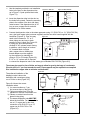
9) CONTROL HUMIDISTAT
The Series EHU-700 is capable of accepting controls
signals with the following characteristics:
a.
Figure 9-1
3"
(75 mm)
0-10 Vdc Humidistat
(Part No. A18609 and A18610) (H200 or H270 series)
b. 1.9-3.9 Vdc Humidistat
(Part No. C1471 or C1472)
5-1/2"
(140 mm)
c. 4-20mA, 250 Ω input impedance.
d. 0-10 Vdc, 50 kΩ input impedance.
e. 0-5 Vdc.
f.
0-135 ohms.
g. on/off
To adapt the EHU-700 to these different types of control humidistats, jumper BJ4 and BJ5 on the printed circuit board (Figure 9-1) must be manually changed and the humidistat must be wired to the
appropriate connections of terminals 1, 2 & 17. Refer to Figure 9-1 or the sticker on the inside of the
cabinet for proper jumper locations.
Chart 9-1
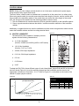
Figure 9-2
Pressure Loss in Copper Pipe
(40' Equivalent Run)
5
1-1/4"
4
1-1/2"
3
In. WC
2
2"
1
10
20
30
40
50
60
70 80
90 100 110 120
#/Hr. Steam
9
Feet of equivalent copper pipe for copper
pipe fittings
Fitting
1-1/4
1-1/2
2
45° Elbow
1.0
2.2
2.8
90° Elbow
2.5
4.3
5.5
90° Long Elbow
1.5
2.7
3.5
Tee
5.0
9
12
Figure 10-1
Modulating
High Limit
Sensor
Safety
High Limit
Humidistat
(optional)
6 - 10 Ft.
Outdoor
Temperature
Sensor
Air Flow Switch
Outside Air
Humidifier
Location
Main Humidity Sensor
Humidifier
Connections
Wall Mounted Control Humidistat:
Wall-mounted humidistats are usually installed 4 ft. to 5 ft. above floor level. Often, the best location is
beside a thermostat that controls temperature in the same space that is to be humidified, if that location meets the following criteria:
• The control humidistat should be located where it will be exposed to the average air condition of the
space to be humidified.
• Avoid areas of restricted air circulation, or locations where the sensor will be subjected to air drafts,
localized heat, or moisture sources.
• Locations near coffee machines, computer blower outlets, doors to other rooms, or windows that
can be opened are not suitable.
10
Figure 11-1
On-Off Humidistat
Switch Opens on RH Rise
1.9 - 3.9 Vdc
Voltage Source
Ground
Stat In
N/C
17
2
1
20
Black
White
Green
Part No.
C1471
or
C1472
Voltage Source
Ground
Stat In
N/C
17
2
1
20
Brown
Orange
Part No.
A8581
or
A8581A
Set BJ4 Stat Input Selector to 1.9 - 3.9 Vdc
Set BJ5 Voltage Source to 12 Vac
Set BJ4 Stat Input Selector to On/Off
Set BJ5 Voltage Source to +5 Vdc
4-20 mA & 0-10 Vdc Setting*
0-135 Ω Ohm Potentiometer
Voltage Source
Ground
Stat In
N/C
17
2
1
20
Voltage Source
Ground
Stat In
N/C
+
Set BJ4 Stat Input Selector to
0-10 Vdc or 4-20 mA
17
2
1
20
Part No.
A6707A
or
A18611
Humidity
Increase
Set BJ4 Stat Input Selector to 0-135 Ohm
Set BJ5 Voltage Source to +5 Vdc
*See Figure 10-1 for Armstrong 0-10 Vdc Humidistat Connections
Duct Mounted Control Humidistat:
Duct-mounted control humidistats are also available for installation where sensing and control of return
air or exhaust air ducts is preferable. (Figure 10-1)
Please refer to manufacturer's recommendations for further information on the location, mounting, and
operation of the various control humidistats.
10) HIGH LIMIT DUCT HUMIDISTAT
Remove the jumpers tab from terminals 10 & 14 and wire the high limit stat between these
terminals. Refer to Figure 10-1 and Figure 11-1 (the overall wiring diagram) for more information.
A duct mounted high limit humidistat is recommended to prevent over-saturation of the duct air.
Use an on-off controller that opens on fault (high humidity). Humidistat should be set for a
maximum of 90% RH. Alternately, a modulation high limit humidistat may be used on applications
such as variable air volume (VAV). Locate the high limit humidistat approximately 10' (3m)
downstream of the dispersion manifold. If 10' (3m) is not available, consult the factory.
11) AIRFLOW SWITCH
An airflow switch is recommended to deactivate the humidifier when there is insufficient air flow in
a duct system. A duct pressure switch is preferred as an airflow sensor. The pressure switch
should open on insufficient airflow (opens on fault). Airflow switch should be mounted in supply air
duct upstream of humidifier dispersion. Remove the jumper tabs between terminals 9 & 15 and
wire the airflow sensor between these terminals. See Figure 11-1 and Figure 12-1 (the overall
wiring diagram) for more information. Complete installation and wiring instructions are contained
in the duct pressure switch package.
NOTE: LIMIT SWITCHES (HIGH LIMIT AND AIRFLOW SWITCHES) OPEN ON FAULT.
11
Figure 12-1
24 VAC
Drain Valve A
Steam
Generator A
High Water
Switch A
Low-Voltage
Low-Energy
Controls
Panel Switches
Mode
Tank
Drain
Select
On/Off On/Off
24 VAC
Fill Valve
Main Control
Humidistat
Micro Controller
Printed Circuit
Board
High Limit*
Humidistat
Current
Transformer
Air Flow*
Switch
24 VAC
Contactor
N.O. Alarm
Relay
LED
Display
*Must be closed to run
Side 1
Three-Digit
Numerical Display
Side 2
24 V Secondary
Power Transformer
High Voltage
Terminals
12) AUDIBLE ALARM
There is an external alarm circuit provided. When an alarm condition is detected in the diagnostic
routines, a relay contact closes allowing activation of an external Class II device connected
between terminals 27 & 28. This circuit is rated to 1 amp.
12
INSTRUMENT PANEL
MODE BUTTON,
INDICATOR,
and DISPLAY
DEMAND
CURRENT
% POWER
DIAGNOSTIC
FILL
DRAIN
HIGH WATER
TANK OFF
MODE SELECT
The Mode select button is depressed for
approximately ½ second to switch both the
"display mode selected" indicator and the 3
digit display between:
-DEMAND- % of humidistat control range.
-CURRENT- actual current in amps.
-% POWER- ratio of current draw to the
nominal rating of the unit.
-DIAGNOSTIC MODE- readout of diagnostic
codes.
Leaving the display in the diagnostic mode for 10 seconds initiates
the input/output diagnostic routine (see Diagnostics pg. 20).
The 3 digit display also exhibits a diagnostic code in the event that
the unit has shut down automatically.
TANK ON/OFF
DRAIN ON/OFF
FILL LIGHT
Indicates when the fill valve is energized to add water to the steam
generator.
DRAIN LIGHT
Indicates when the drain valve is energized to drain water from the
steam generator.
HIGH WATER LIGHT Indicates that the water level in the generator has risen to the high
water level.
TANK OFF LIGHT
TANK ON/OFF
MANUAL DRAIN
BUTTON
Indicates when power to the generator has been interrupted (tank
contactor open).
Depressing the tank on/off button for ½ second will open the tank
contactor. The tank off light and the diagnostic light will be on and the
display will show the message CO8. The unit will stay in this mode
until the button is pressed again.
Depressing the manual drain button for ½ second will open the drain
valve. The tank will continue to drain until the button is pressed again.
13
START-UP PROCEDURE FOR ARMSTRONG SERIES EHU-700 HUMIDIFIERS
The following steps should be performed on all newly installed Series EHU-700 Humidifiers to ensure
that the humidifier and the entire humidification system functions correctly.
BEFORE TURNING ON THE POWER
Figure 14-1
1) Examine the wiring and the components
in the electrical compartment.
2) Check for any loose wires or quickconnect terminals that may have been
pulled loose.
3) Using a screwdriver, TIGHTEN ALL
SCREW TERMINALS on the power
supply terminal block, ground lug, and
contactor (Figure 14-1).
Current
Transformers
Make sure all steam generator tank
connections are tight. Remember, a
loose joint is a HOT joint and could be a
fire hazard!
4) Locate the low voltage terminal block
(Figure 14-1).
Contactors
Power Supply
Terminal Block
Verify that an airflow switch is
connected between terminals 9 and 15
or that there is a jumper installed. If an
airflow switch is installed, ensure that
there is airflow.
Verify that a high limit stat is connected
between terminals 10 and 14 or that a
jumper is installed.
5) Turn on the water supply - Check for
leaks.
Low Voltage
Terminal Block
TURN ON POWER AT THE CIRCUIT BREAKER
6) The following should happen:
a) The Demand Mode and Tank Off lights will be illuminated. The stat demand will be
displayed.
b) If the stat demand displayed is greater than 35%, the Tank Off light will go out and a few
seconds later the Fill Light will go on. The unit will begin to fill.
14
If the stat demand display is greater than 35% and the unit does not begin filling,
press the mode select button three times and the diagnostic mode indicator will
light. Note the diagnostic message and refer to the diagnostics information in the
troubleshooting section of this manual (page 20).
c) If the stat demand is less than 35%, force a 100% humidity demand by setting
humidistat dial to 95% RH. Alternately, a 100% demand can be simulated by setting
BJ4 jumper to position 3-4 (on/off), set BJ5 to position 1+2 (5 VDC) and installing
a jumper between terminals 17+1 of the low voltage terminal block inside humidifier.
7) Let the unit continue to fill and allow the water to boil.
a) If the water level reaches within 4" of the Steam Generator Tank top, the High Water Float
Switch will block the fill and illuminate the High Water light momentarily. This is normal on
relatively pure water. Pressing the mode button to check the diagnostic display will result in
an indication of C01. To complete the start-up testing in this instance, push the Drain switch
to drain 1/2 of the tank. Next, turn off power at the breaker or safety switch and add one
pinch (1/2 teaspoon) of Epsom salts to the Fill Cup (See Part #25 on Page 28). This should
allow the water to boil by increasing the water's conductivity. (See "Water Quality and
Treatment for EHU Humidifiers" in the troubleshooting section on page 23.) Reapply power
to energize the humidifier.
8) On typical beginning fill, after the fill stops, press the mode button until percentage of maximum
power is indicated. The numerical display should read a few points above 40%.
9) Press the Drain switch. Verify that the unit is draining freely.
10) Inspect the steam outlet piping. Verify that there are no un-trapped low spots. Also verify that the
piping is insulated and properly sloped (See Step 8 on Page 7).
11) If the Dispersion Tube is equipped with a drain fitting, verify that is working.
12) Verify operation of high limit humidistat and or air proving switch, if used.
a) If high limit is used, turn dial to minimum setting, 10%. Display of unit should read CO4 and
unit should stop steam production. Turn humidistat dial to maximum of 90% and unit should
return to normal operation.
b) If pressure switch is being used, verify airflow condition in duct or air handler.
- If air flow is present, unit should be in normal operation. Disconnect wire from terminal
15 at humidifier. Display should show CO3, and unit will stop operation. Reconnect wire to
terminal 15, and unit should return to normal operation.
- If Air Flow is not present in Duct or Air Handler, unit should be sitting IDLE and Display
should be showing CO3. Turn fan on and verify duct or Air handler now has airflow
present. Unit should return to normal operation.
13) While humidification is being demanded, turn humidistat dial down to near zero. The following
should happen:
a) The stat demand reading will decrease to zero.
b) The unit will shut down, lighting the Tank Off light.
14) Turn humidistat dial to the desired value.
15
15) Verify that all of the input/output circuits are functioning properly by entering the input/output
diagnostics mode. Press the mode button until the diagnostics indicator lights and wait ten
seconds. The unit will do a complete self-diagnostic check. See CO in the diagnostics section of
this manual (page 20) for more information.
16) Turn power off, if humidification is not needed.
17) Close and lock the doors, and store the key away from the unit.
16
TROUBLESHOOTING GUIDE
CAUTION!: Disconnect the electric power supply at the circuit breaker or switch whenever the
unit is to be inspected or serviced. DO NOT USE THE TANK ON/OFF SWITCH ON THE HUMIDIFIER BECAUSE THIS SWITCH DISCONNECTS THE STEAM GENERATOR TANK ONLY.
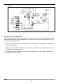
PRINCIPLE OF OPERATION - AN OVERVIEW
The Armstrong Series EHU-700 electronic steam humidifier
converts ordinary tap water to steam and distributes it within
the air being humidified to bring the relative humidity up to
the desired level.
The humidity demand is sensed by the humidistat. A microcontroller converts this demand signal into an amperage
requirement. If humidistat demand is above 35%, the internal
power contactor closes, applying voltage to the electrodes,
and the fill valve opens to begin filling the tank. Water enters
the bottom of the steam generator tank and rises until it
reaches the electrodes. Upon contact, electrical current flows
through the water, causing it to boil and produce steam
(Figure 17-1).
As the water level rises (Figure 17-2) increased electrical
current flows through the water, producing more steam. This
increase will continue until the desired current level (i.e.
required steam output) is reached. At this point, the fill valves
will cycle off and on to maintain the desired amperage ±5%.
The desired current level is a function of the nominal current
rating, humidistat demand, and the automatic capacity adjustment feature.
When the humidistat senses the added moisture in the air,
the demand for humidity begins to drop. As the demand
drops, the output of the unit is modulated down by boiling
away water and not filling. This allows the amperage to
decrease, thereby reducing the steam flow. The fill valve can
then cycle at the lower steam output (current) requirement.
When the humidistat demand signal drops below a minimum
25% demand, the contactor is de-energized, and steam output stops (Figure 17-3).
Steam output may also be stopped by a duct high-limit
humidistat or a fan interlock switch. These devices prevent
excess moisture and condensation in the duct by opening the
tank contactor if there is too much humidity or insufficient airflow within the duct.
Figure 17-1
External
Disconnect
Internal
Power
Contactor
Current Sensor
Line
Fill Valve
Controlling
Humidistat
Distribution
Tube
Fill Cup
High-Limit
Humidistat
Fan Interlock
High-Water
Float Switch
Controller
Drain Valve
Overflow
Line
Figure 17-2
External
Disconnect
Internal
Power
Contactor
Current Sensor
Line
Fill Valve
Controlling
Humidistat
Distribution
Tube
Fill Cup
High-Limit
Humidistat
Fan Interlock
High-Water
Float Switch
Controller
Drain Valve
Overflow
Line
Figure 17-3
External
Disconnect
Internal
Power
Contactor
Current Sensor
Line
Fill Valve
Controlling
Humidistat
Distribution
Tube
Fill Cup
High-Limit
Humidistat
Fan Interlock
High-Water
Float Switch
Controller
Drain Valve
Overflow
Line
17
A high-water float switch prevents water carry-over into the duct due to an excessive water level in the
tank. When the high water limit is reached the HIGH WATER light comes on and the fill valve is
blocked until some water is boiled away and the water level drops. This is common during startup. If
the high water light comes on and the water level is in the lower half of the steam generator, contact
the factory for assistance. This is due to high static pressure. Installation of fill cup extension kit could
be required.
If an overcurrent situation is detected, the overcurrent protection circuit will drain water from the tank
to reduce current flow. If the overcurrent persists, the contactor will be de-energized to stop all current
flow.
The Series EHU-700 patented automatic capacity adjustment feature eliminates manual adjustment
and improves humidity control. This feature automatically adjusts maximum output up or down
depending on the humidity demand history. When the unit is first turned on the maximum output is
40%. If the demand stays high, the unit automatically steps up the maximum output and will reach
100% maximum output after one hour. For test purposes, or for special operating situations, this feature can be easily over-ridden by changing the position of jumper BJ1 on the printed circuit board from
pins 1 and 2 to pins 2 and 3.
An automatic drain cycle blows down mineral-laden water to increase steam generator life and reduce
maintenance requirements. The frequency and duration of the drain cycle will vary with supply water
conductivity, steam output, and humidistat demand history. When it is initiated automatically, the drain
valve cycle occurs at the beginning of a fill cycle. The incoming cold water tempers the drain water to
less than 160ºF after 72 hours of no demand, the unit will initiate an "End-of-Season" drain to remove
stagnant water.
OPERATIONAL GUIDELINES
This section describes the conditions and indications you should expect to find in a normally operating
humidifier.
Tank Contactor Operation:
The microcontroller will de-energize the contactor, turning off the current to the electrodes if ANY of
the following occur:
1. The control humidistat demand signal is less tan 25%.
2. The fan interlock circuit is open.
3. The high limit humidistat circuit is open.
4. The tank current is greater than the over-current limit.
Conversely, the microcontroller will energize the contactor, turning on the current to the electrodes,
only if ALL of the following occur:
1. The control humidistat demand signal is greater than 35%.
2. The fan interlock circuit is closed.
3. The high limit humidistat circuit is closed.
There is a time delay of fifteen seconds in the contactor operating circuitry to prevent it from cycling
too rapidly after it has been turned off.
Monitoring Stat Demand:
Indicates the demand for humidity in relationship to the control range of the humidistat. 0% indicates
that the humidity requirement has been exceeded. 100% indicates that the humidistat is calling for full
humidifier output. In general, a reading of around 50% indicates that the set point has been met.
18
Monitoring Current:
While the unit is filling, the current should increase. As the current approaches the maximum rating of
the unit, it increases more slowly, especially in higher capacity units. With the tank on, and the fill and
drain circuits idle, the current should fall slowly. When the unit is draining, the current should decrease
at a moderate rate.
Monitoring % Power:
The percentage power equates to the percentage of maximum steam output. The percentage power
reading will increase and decrease proportionally to the current draw. Overcurrent protection circuitry
starts initiating drain cycles as the % power reading approaches 110%. The overcurrent failure routine
is initiated at about 120%.
Automatic Drain Operation:
The microcontroller will energize the drain valve at the beginning of the fill cycle to reduce the conductivity and mineral build-up in the tank. It will vary in drain duration to adjust for changes in water quality, demand history, and steam output.
Manual Drain Mode:
If the manual drain button is pushed while the tank circuit is energized, the fill valve will also open to
temper the drain water. If the tank is off, only the drain valve will open.
19
EHU-700 DIAGNOSTICS
THE Series EHU-700 has built in diagnostics to detect system problems early, before they become
severe. If possible, the diagnostic routine performs corrective measures. If necessary, the unit is shutdown and a dry contact is closed to enable a remote alarm.
The diagnostic messages that result in the unit being shutdown are displayed automatically. The other
messages are displayed when the diagnostic display mode is selected with the mode switch. If the display mode selection is left in the diagnostic mode for 10 seconds, the Input/Output circuit diagnostic
check will begin.
DIAGNOSTIC DISPLAY MESSAGES
C00 = NORMAL OPERATION
C01 = HIGH WATER
C02 = TANK NEEDS CLEANING*
C03 = INTERLOCK CIRCUIT
C04 = HIGH-LIMIT CIRCUIT
C05 = DRAIN SYSTEM FAILURE*
C06 = FILL SYSTEM FAILURE*
C07 = OVERCURRENT FAILURE*
C08 = MANUAL TANK SHUT-OFF
C09 = I/O DIAGNOSTICS
* Automatic shutdown and Alarm contact closure.
C00:
NORMAL OPERATION
C01:
HIGH WATER:
A high-water float switch prevents water carry-over into the duct due to too high a water level in
the tank. When the high water limit is reached the HIGH WATER light comes on and the fill
valve is blocked until some water is boiled away and the water level drops. This is not
uncommon on startup. The diagnostic display mode will indicate C01.
NOTE: the high water light goes off as soon as the high water condition is cleared but the
operation on the fill valve does not resume until after a fifteen second delay period. If C01 is
displayed and the water level is in the lower half of the steam generator, high static pressure
exists, contact the factory for assistance.
C02:
TANK NEEDS CLEANING:
If the HIGH WATER lights is on continuously during normal service (i.e. after initial startup) and
the current is not increasing, the tank probably needs cleaning (refer to the maintenance
section of this manual). If this condition persists without being serviced, the display panel will
display diagnostic message C02. The unit will shutdown and the dry contact will close to
activate the remote alarm. NOTE: False C02 messages may occur if incoming water is very
pure (< 100 μMhos/cm²). Please consult factory.
C03:
INTERLOCK CIRCUIT:
The fan interlock circuit may be a sail switch or (preferably) a duct pressure switch. When air
flow in the duct is not present, the interlock circuit should open and the microcontroller will
de-energize the contactor. The diagnostic mode will display the message C03 and the fill
solenoid is blocked.
20
C04:
HIGH LIMIT CIRCUIT:
When the humidity in the duct reaches the high limit stat set-point, the circuit will open and the
microcontroller will de-energize the contactor. The diagnostic mode will display the message
C04 and the fill solenoid is blocked.
C05:
DRAIN SYSTEM FAILURE:
This routine checks for a failure to reduce current if the drain valve is energized for more than
five seconds. If the actual current does not decrease when the microcontroller demands a drain
cycle, the unit will go into a diagnostic routine. This routine will try twice to correct the drain
system failure by cycling the drain valve rapidly. If the failure is not corrected, the unit will shut
down. The tank off indicator will light, the numerical display will show C05 (the drain valve
failure message), and the dry contact will close to activate the remote alarm.
Drain system failure can be due to a plugged drain valve, drain valve solenoid failure, scale
buildup in the tank, or drain piping problems. Refer to the maintenance section of this
manual for resolution of these problems.
C06:
FILL SYSTEM FAILURE:
After start-up, if the fill valve is on and has been on for more than four minutes, the
diagnostic routine will check the fill valve operation. If the actual amp signal is less than the
current when the fill valve was opened, the unit will go into a diagnostic routine. If the problem
cannot be corrected, a fill system failure will be triggered and the unit shut down. The three
digit display will show C06 to indicate this condition, and the dry contact will close to activate
the remote alarm.
Fill system failure can be due to excessive or insufficient inlet water pressure, a failed fill valve
solenoid, a plugged fill valve failed open, or a backflow preventer. Refer to the maintenance
section of this manual for resolution of these problems.
C07:
OVERCURRENT FAILURE:
The overcurrent limit (OCL) is 20% above the nominal amp rating of the unit. When the actual
current reaches the OCL, the microcontroller will de-energize the contactor and energize the
drain valve for 15 seconds. Then the contactor will be re-energized to see if the drain valve has
corrected the overcurrent condition. This procedure is repeated 5 times.
If the overcurrent still exists, an overcurrent failure indication of C07 is displayed, the unit is
shut down, and the dry contact will close to activate the remote alarm. The unit will have to be
manually reset and the overcurrent condition addressed by the maintenance personnel.
An overcurrent failure can result from the cold startup of a tank that was previously running at a
high load, resulting in the tank water becoming too conductive for start-up. If this is suspected,
manually drain the tank for 15-30 seconds, then try to restart the system. If the overcurrent
failure repeats, the drain system could be partially plugged, or the tank may be in need of
cleaning. Refer to the maintenance section of this manual for resolutions to these
problems.
C08:
MANUAL TANK SHUT-OFF:
The tank on/off button will de-energize the tank contactor. The tank off light and the diagnostics
indicator will be on and the display will show the message C08. The unit will stay in this
condition until the button is pressed again. In the tank off mode, the manual drain button is still
active, but the mode select button is not.
21
C09:
I/O DIAGNOSTICS
If the display mode selection is left in the diagnostic mode for 10 seconds, the Input/Output
circuit diagnostic check will begin. The display will show the message C09, the tank will be off,
and the diagnostics mode light will remain on.
Output Circuits: The diagnostics will first check all the output circuits: fill valve, drain valve,
and tank contactor to make sure they are working. When a light comes on, you will hear the
corresponding valve or contactor circuit energize for about 2 seconds. Each circuit is checked
twice before proceeding to the next circuit.
Input Circuits: Next the microcontroller checks the status of all input circuits, beginning with
the control stat. the 3 digit display will show 0% Demand, then the actual stat demand. It will do
this twice. The input diagnostics continues by checking the fan interlock switch, high limit duct
humidistat, and high water switch. The display will now show C09 followed by any additional
messages that indicate problems with the input circuits.
When the I/O diagnostic check is finished, the demand mode light will be on, the display will
show the control stat demand and the unit will return to normal operation. The complete I/O
diagnostic check lasts less than 2 minutes.
22
WATER QUALITY AND TREATMENT FOR EHU SERIES HUMIDIFIERS
GENERAL
Series EHU 700 electronic humidifiers use ordinary tap water in their operation. The quality of this
water affects both the operation and the maintenance of the humidifier.
How the EHU works:
The EHU is an electrode boiler. When no water is present, the electrodes are separated by air, an
insulator, so no current flows. When tap water contacts the electrodes it conducts current between the
electrodes, heating the water.
How much current passes between the electrodes is dependent on the conductivity of the water, which
is measured in micromhos/cm (μMhos/cm). EHUs can operate effectively with water conductivity in the
range of 50 (low) to 800 (high) μMhos. For conductivity greater than 800 μMhos, please consult factory. The optimum incoming water conductivity level is 200-400 μMhos/cm. the greater the conductivity
of the water, the lower its level will be in the tank in order to draw a given current. In general, the EHU700 Series will adjust its drain cycle to maintain the water level around 1/3-1/2 full in the tank.
What affects conductivity?
The minerals (mainly calcium) dissolved in the water. Pure water is NOT conductive and can't be used
exclusively in an EHU without special procedures. This includes distilled, de-ionized and reverse
osmosis diffusion treated water. Most tap water is conductive however, so it will work in an EHU. If tap
water is not available, consult with the factory.
How does this affect maintenance?
Generally, the more conductive the water is, the more
minerals there are dissolved or suspended in it. As the
water is boiled away these minerals can be left as a
deposit on the electrodes, tank, and fittings. Any
deposits that build up can block valves, diminish the
internal volume of the tank, and form an insulating barrier
on the electrodes (Figure 23-1).
Figure 23-1. Tank filled with mineral buildup.
The EHU automatic drain cycle:
All Series EHU humidifiers have a built in blow down
circuit to intermittently purge excess mineral accumulations from the water. The drain cycle should
automatically adjust for variations in water quality. Eventually, however, minerals will accumulate in
the steam generator, and have to be removed (see tank cleaning in the maintenance section of
this manual).
Water treatment guidelines for the EHU:
Generally, the EHU will work with any potable water source. If you are experiencing problems with
your installation, however, the following suggestions may be helpful in identifying and rectifying your
difficulty.
WHEN WATER CONDUCTIVITY IS TOO LOW
Indicators:
-Unable to reach humidity set point in space.
-High water level in tank
-Low current draw and low % power reading even though the stat demand remains at 100%.
-Consistent drain cycles of two seconds or less.
23
Results:
-Excessive time needed to reach set point during star-up.
-Poor humidity control.
Remedy:
-Add 1/2 teaspoon of Epsom salts to the fill cup. After start-up the automatic drain program
should maintain the unit at full capacity.
-If problem persists, contact the factory.
WHEN WATER CONDUCTIVITY IS TOO HIGH
Indicators:
-Water level just touching tip of electrodes.
-Arcing and foaming in the tank.
-Frequent drain cycles (every time the fill valve opens) that last up to 10 seconds.
Results:
-Tank frequently needs cleaning.
-Poor control because of excessively low water level.
-Electrode destruction.
Remedies:
-If you have pure water available such as: de-ionized water, Reverse Osmosis diffusion water,
or distilled water, they can be blended with tap water to reduce the total mineral content. Pure
water alone is not conductive enough to pull current. The water is too pure when the "Tank
Full" light comes on excessively. Consult a water purification equipment vendor for the proper
blending equipment or the Armstrong factory for more information regarding use of purified
water. The blended water conductivity should be in the 200-400 μMhos/cm range.
-Softened water is not recommended for use with the Series EHU-700 Humidifiers.
Water softeners replace the calcium ions in the water with sodium ions. As softened water
boils, the sodium ions stay in solution causing the conductivity of the water in the tank to
increase rapidly.
CAUTION: Soft water may increase the tank's water conductivity and does not allow a
protective coating to form on electrodes. Also, as salts stay in solution more drainage
will be needed to maintain correct water conductivity in the tank. Please consult factory
for softened water analysis, if softened water source is available, before proceeding.
Expect to replace electrodes more frequently. Discontinue service if continuous arcing
or foaming occurs in the tank.
24
EHU-701, -703, -704 Series
Electronic Steam Humidifier
Repair Parts
Steam Generators Complete
Item
Part No.
*1A
D4417
*1B
D4418
*2A
*2B
Description
1 Ph Low Voltage
120,208,240,277 Volts
Used On
701
D4415
1 Ph High Voltage w/Barrier
380,480,600 Volts
3 Ph Low Voltage (208, 240, 277 volts)
701
D4416
3 Ph High Voltage w/Barrier (380, 480, 600 volts)
701
3A
D262A
3 Ph/1 Ph Low Voltage (120, 208, 240, 277 volts)
3B
D262
3 Ph High Voltage w/Barrier (380, 480, 600 volts)
Note: A replacement generator comes with a spare drain adaptor "O" Ring.
701
703,704
703,704
Steam Generator Parts
Item
Part No.
Description
Used On
† *4A
D4422
Tank Assembly Less Electrodes - 1 Phase
701
† *4B
D4423
Tank Assembly Less Electrodes - 3 Phase
701
†6
D263
Steam Generator Bottom Half-Less Drain Screen
703,704
†6
B3968
Steam Generator Top Half- Holes Drilled
703,704
*7A
B3038
Electrode Replacement Assembly 1 Ph
High & Low Voltage
701
*7B
A10077
Electrode Replacement Assembly 3 Ph
701
A9745
Electrode Replacement Set (Includes 6 ea. electrodes,
O-Rings, 1/4" Nut & 1/2" Nut) 1 Ph/3 Ph
8
703,704
*9A
A9742
Drain Screen for Low Voltage (120, 208, 240, 277)
701
*9B
B2413D
Drain Screen/Barrier Assembly For High Voltage 1 Ph
701
*9C
C1965
Drain Screen/Barrier Assembly For High Voltage 3 Ph
10
C2053
Drain Screen
703,704
11
A9746
Tank Barrier Assembly
703,704
12A
A21374
O-Ring for Steam Generator
701
12B
A21375
O-Ring for Steam Generator
703,704
*13
C1839
V Band Tank Clamp
14
B2822
Tank Retainer Clip
701
701
703,704
*Item Not Shown.
† These parts are furnished as a convenience to our customers. Part dimensions may change in service.
Armstrong cannot guarantee that new parts will fit your used parts.
See Drawings on Page 28
25
Valves and Mechanical Parts
Item
Part No.
15
B2717
Description
Used On
Drain Valve Assembly w/ Hose & (2) Clamps
701,703,704
701,703,704
16A
B2582A-1
Float Switch Assembly
16B
B2582A-2
Float Switch Assembly (Far Tank)
704
17A
B4482
Fill Valve w/Flow Washer & Straight 3/8" Compression Fitting
701
17B
B4480
Fill Valve w/Flow Washer & 90 Degree 3/8" Compression Fitting
703
17C
B4481
Fill Valve Assembly Less Flow Washer
704
18A
A8608
O-Ring for Tank Drain Adapter
701
18B
A9617
O-Ring for Tank Drain Adapter
703,704
19A
C2042
Tank Drain Adapter Less O-Ring
701
19B
C2078
Tank Drain Adapter Less O-Ring
703, 704
20
D248
Drain Cup
21
A9571
Screw, Drain Cup #10-32 (2" Long)
701,703,704
22
B2859
Gasket, Drain Cup
701,703,704
Fill Cup
701,703,704
23
C1838A
*24
B2929
25
A9016A-12
*26
A9016-2
*27
701,703,704
Mounting Bracket, Fill Cup
703,704
Tube, Fill Valve to Fill Cup 27-1/2" x 3/8"
701,703
Tube, Fill Valve to Fill Cup Tee, 1-1/2" x 3/8" (Reinforced)
704
A9016A-9
Tube, Fill Cup Tee To Cup #1, 21" x 3/8"
704
*28
A9016A-13
Tube, Fill Cup Tee To Cup #2, 38" x 3/8"
704
29A
A8567-18
Tube, Fill Cup Overflow 19" x 5/8"
701
29B
A8567-17
Tube, Fill Cup Overflow 31" x 5/8"
703,704
30A
A8567-19
Tube, Fill Cup to Tee, 9-1/2" x 5/8"
30B
A8567-11
Tube, Fill Cup to Tee, 14" x 5/8"
31A
A9016A-8
Tube, Tee to Float Switch, 10-1/2" x 3/8"
31B
A9016A-2
Tube, Tee to Float Switch, 17" x 3/8"
701
703,704
701
703,704
32A
A8567-19
Tube, Tee to Adapter, 9-1/2" x 5/8"
701
32B
A8567-16
Tube, Tee to Adapter, 12-1/4" x 5/8"
703,704
33
A8567-10
Tube, Adapter to Drain Valve, 1-3/4" x 5/8"
701,703,704
34
A9620-1
Tube, Tank/Cabinet Drain, 18" x 1"
701,703,704
*35
*36
*37
B2740
B2578
A9472
Flow Control Tee (Fill Cup Tee)
Float Switch Chamber Bracket
Fill Tubing Tee
704
701,703,704
701,703,704
*38
B2250
Steam Hose, ID 1-1/2" x 9-5/8"
701,703,704
*39
B2851
Steam Hose, ID 2" x 12"
40A
B2716-11
40B
*41
703,704
3/8" Tube Flat Hose Clamp used at Float Switch/Fill Valve
701,703,704
B2716-15
3/8" Tube Flat Hose Clamp used at Fill Tee/Fill Cup
701,703,704
B2716-18
5/8" Tube Flat Hose Clamp
701,703,704
42
B2911-8
Drain Valve Hose Clamp
701,703,704
*43
A8433-5
1-1/2" Steam Hose Clamp
701,703,704
*44
A8433-10
2" Steam Hose Clamp
*45
B2911-6
7/8" Fill Cup Tee Hose Clamp
*63
A9472
* Item Not Shown
703,704
704
Pipe Tee 5/8" x 5/8" x 3/8"
703,704
See Drawings on Page 28
26
Electrical Parts
Item
Part No.
Description
46
C2059
Display PC Board
47A
A22925
Used On
701,703,704
47B
A22926
Control PC Board Less Current Module
Control PC Board Less Current Module
701
48A
B2895-7
CM-7 Current Module
48B
B2895-12 CM-12 Current Module
701,703,704
48C
B2895-14 CM-14 Current Module
701,703,704
48D
B2895-16 CM-16 Current Module
701,703,704
48E
B2895-20 CM-20 Current Module
701,703,704
48F
B2895-24 CM-24 Current Module
701,703,704
48G
B2895-32 CM-32 Current Module
701,703,704
48H
48I
B2895-40 CM-40Current Module
701,703,704
703,704
701,703,704
B2895-48 CM-48 Current Module
701,703,704
49
B1992B
Current Transformer
701,703,704
50
B2721
Elec Contactor 50 Amp
701,703,704
51
A10094
Fuse, 3 Amp, Set of 2
701,703,704
52A
C1833
Power Transformer (120v)
701,703,704
52B
C1833F
Power Transformer (208v)
701,703,704
52C
C1833G
Power Transformer (240v)
701,703,704
C1833C
Power Transformer (277v)
701,703,704
C1833H-1 Power Transformer (346v)
701,703,704
52D
52E
52F
52G
Power Transformer (380v)
701,703,704
C1833H-2 Power Transformer (415v)
C1833D
701,703,704
52H
52I
C1833B
Power Transformer (480v)
701,703,704
C1833A
Power Transformer (600v)
701,703,704
53
B2857
Cable Assy-Hex Display
701,703,704
54
B2856
Cable Assy-LED Display
701,703,704
55A
D348
Wire Harness
701
55B
D296
Wire Harness
703,704
56A
B2419
Tank Power Lead w/Terminal 19-1/2"
701
56B
B2853-13 Tank Power Lead w/Terminal 36"
703,704
56C
B2853-14 Tank Power Lead w/Terminal 50"
704
57A
B2334-11 Contactor Power Lead 12-1/2"
701
57B
B2854-1
Contactor Power Lead 5-1/2"
703,704
*58A
B2925-1
Tank Jumper Lead 10" 1 Ph
703,704
58B
B2925-2
Tank Jumper Lead 14-1/2" 3 Ph
703,704
*59
B2718-1
Wire Ext. for Contactor #2
*60
B2718-3
Wire Ext. for Drain Valve #2
61
A8649
62
B2414-3
704
704
Fuse Block
701,703,704
Quick Disconnect 3 Terminal Block
701,703,704
*Item Not Shown
See Drawings on Page 28
27
Figure 28-1. EHU-700 Parts List
23
40
47
29
49
56
48
54
16
53
25
46
62
30
55
31
50
32
18
52
19
51
33
61
57
15
22
20
21
42
17
Figure 28-2. EHU-700 Steam Generator Repair Parts List
6
8
14
12
6
11
10
18
3
28
34
MAINTENANCE
RECOMMENDED MAINTENANCE SCHEDULE
1 TO 2 DAYS AFTER
START UP
1)
2)
3)
4)
5)
Check unit operation.
Look in drain pan for leaks.
Check steam piping for leaks.
Observe duct low points for signs of poor humidity distribution.
Be sure unit is draining freely by pushing the manual drain
button (the manual tank off button should not be depressed).
1 MONTH TO 1 YEAR
1) Repeat the 5 steps outlined above.
2) Clean, repair, or replace steam generator.
STEAM GENERATOR MAINTENANCE
General:
The steam generator is basically the only part of the EHU that requires regular maintenance. This
maintenance may include cleaning or replacing the tank itself or the electrodes. We recommend substituting a spare generator in order to minimize downtime and labor requirements. The replaced generator may then be serviced when it is convenient.
Tank Cleaning:
As the water in the steam generator boils away, the minerals in that water come out of suspension and
are deposited on the walls of the tank and on the electrodes. This process leaves the tank walls coated with a white or light brown colored mineral buildup. This buildup may be anywhere from soft and
chalky to rock hard. The automatic drain cycle will minimize mineral buildup but, eventually, the tank
will need cleaning.
Tank cleaning is indicated when:
a) The unit has been in service for a period of time, a solids buildup is visible through the tank
walls, and the "normal" water level in the tank is rising, or;
b) The tank cleaning message (C02) is displayed.
TO CLEAN THE TANK, PLEASE REFER TO THE "TANK REMOVAL AND REPLACEMENT" AND
THE "STEAM GENERATOR CHEMICAL CLEANING PROCESS" SECTIONS OF THIS MANUAL.
(PAGE 30)
Tank Replacement:
Tank replacement is indicated if the tank body becomes deformed in any way, as this could
cause leakage around the o-ring.
TO REPLACE THE TANK, PLEASE REFER TO THE "TANK REMOVAL AND REPLACEMENT"
SECTION OF THIS MANUAL. (Page 30)
Electrode Replacement:
Electrode disintegration generally starts due to high conductivity water being present in the
steam generator. Electrode disintegration sometimes occurs as a result of a combination of the
following factors:
a) High voltage (especially 480 and 600 volts);
b) Hard water (in excess of 20 grains/gal.);
c) Any unit with a malfunctioning drain system;
d) Softened water.
29
If the electrodes begin to disintegrate, the tank may turn black or red, and arcing or flashing
may be visible inside the tank while it is operating. IF YOU NOTICE EXCESSIVE ARCING,
SHUT THE UNIT OFF AND CALL THE FACTORY BEFORE RE-STARTING UNIT.
To replace the electrodes, please refer to the "Tank Disassembly and Electrode Replacement"
Section of this manual. (Page 33)
RECOMMENDED PROCEDURE FOR STEAM GENERATOR TANK AND ELECTRODE
REMOVAL, CLEANING, REPAIR AND REPLACEMENT
TANK REMOVAL AND REPLACEMENT - ALL MODELS
1) Turn steam generator tank off by pressing tank off button.
2) Drain the tank by pressing the drain button. It may take five minutes for a full tank to completely
drain.
3) Once the tank is completely empty, turn off the power at the main disconnect or breaker.
4) Disconnect the steam hose from the top of the steam generator tank by loosening the hose clamp
with a screwdriver or 5/16" nutdriver. BE CAREFUL! The tank may still be hot to the touch, and
some steam may still be condensing in the tank.
5) Disconnect the power leads at the steam generator with a 7/16" wrench (three leads for 3-phase
units, two leads for single phase). See wiring diagram, Figure 12-1, for more details.
6) Remove the tank from the cabinet by lifting it out of the drain adaptor. BE CAREFUL! The tank
may still contain hot steam or condensate.
7) It is preferable that you replace the tank with a new or rebuilt unit and take the current tank to the
shop for servicing.
8) Install the tank into the EHU by lowering it into the drain adaptor. A small amount of high temperature grease or silicone lubricant may be used on the drain adaptor o-ring to help it seal properly.
After a couple of tank replacements the o-ring should de replaced as well.
9) Connect power leads and, on EHU-703 and 704, the loose end of the jumper wires to electrode
studs using a 7/16" wrench (three leads for 3-phase units, two for single phase). Refer to the
wiring diagram in your unit for specific information.
10) Connect the steam hose to the top of the steam generator with the hose clamp.
11) Check all wiring connections at the main power, contactor, and control voltage terminal blocks
(Figure 14-1), as well as on the generator itself. Energize the circuit breaker or main disconnect.
Refer to Start-up Section if you encounter any problems when restarting the unit.
30
STEAM GENERATOR CHEMICAL CLEANING PROCEDURE
This procedure is intended as a guide only for the chemical cleaning of the generator in all EHU models. Read and follow label directions on any cleaning product. Check local codes before disposing of
chemicals.
Caution: Muriatic acid can cause severe chemical burns if not handled properly. Wear rubber gloves
and eye protection when using. Read and follow carefully the safety procedures on the package.
1) Obtain several gallons of muriatic acid. Muriatic acid is the name for commercial hydrochloric acid.
It is available in most hardware, pool chemical, or farm supply outlets.
2) Remove the tank, following the "Tank Removal" directions in this manual.
3) Let the steam generator tank cool after removal from the EHU unit.
4) Split the tank, referring to the directions on page 33 of this manual, and examine the inside of
the tank and the electrodes.
a. If the tank is black or dark brown, the electrodes may have disintegrated and chemical cleaning
may not be effective. The tank can be cleaned with the following process, but the electrodes
may need to be replaced.
b. If tank and electrodes have a white/tan/grey mineral accumulations and/or the tank is partially
filled with loose lime accumulations, proceed with chemical cleaning.
5) Empty any loose deposits from the bottom tank half. Both tank halves and the barrier assembly, if
present, can be cleaned using a scraper, a stiff bristle brush, and water spray as required. Refer
to the directions on page 33 of this manual for details on removing the drain screen for further
cleaning, if necessary.
6) Remove the electrodes from the upper tank half, following the directions on page 33 of this
manual. Loose and/or soft deposits should be scraped from the exterior of the electrodes before
chemical cleaning.
7) Prepare the chemical cleaning solution as per manufacturer's recommendations and fill a plastic
bucket to a sufficient level to soak the electrodes. Be certain not to submerge the electrodes
beyond the level of the screen.
8) Let the cleaning action take place for 15 minutes. Remove the electrodes from the bucket and
rinse them thoroughly with a clean water spray.
9) Observe the electrodes to determine if another treatment is necessary.
10) It is not necessary for the electrodes to be cleaned down to bare metal. Removal of major
accumulations is the only requirement.
11) Helpful Hints:
* Check the drain valve for proper operation & good flow when the tank is drained prior to
removal.
* With the tank removed, inspect the drain adaptor and hose from adaptor to drain valve to
ensure that it is free from deposits which may interfere with proper drainage.
31
12) Reassemble tank. Make sure o-rings are still on electrode terminals. Also check condition of steam
generator o-ring. After a couple cleanings, it will need to be replaced. Make sure o-ring is sealed in
its groove and not pinched when halves are put together. Do not over-tighten nuts that hold
electrodes in place. This is an o-ring seal so nuts should be "snug".
13) Re-install the steam generator tank. Check out for proper operation.
32
TANK DISASSEMBLY, CLEANING, AND ELECTRODE REPLACEMENT
MODELS EHU-703 AND 704, SINGLE AND THREE PHASE
1) Using a 7/16" wrench, disconnect the jumper wires from the steam generator.
2) Remove 24 metal clips by pushing gently on top of each clip with a screwdriver while cupping the
clip with the other hand.
3) Lift the top half of the tank free of the bottom half and rest it on the electrodes. Use a ¾" wrench
to loosen and remove the nuts from the six electrode studs.
4) Lift the top tank half from the electrodes. Remove the o-ring from the lower tank half o-ring
channel and put it aside for re-use. On high voltage units, lift the barrier assembly out of the
bottom tank half.
5) Clean the tank halves and the barrier assembly (Figure 35-1), if applicable, using a scraper, stiff
bristle brush, and/or water spray. Rinse the unit with clear water. If necessary, the drain screen
may be removed for cleaning by removing three screws and pushing up through the bottom tank
connection with a screwdriver handle or other blunt object. The drain screen snaps back into place
and is SECURED BY THE 3 SCREWS after cleaning. BOTH THE BARRIER ASSEMBLY AND
THE DRAIN SCREEN SHOULD BE REPLACED WITH NEW PARTS IF THEY ARE
UNSERVICEABLE.
6) Install one electrode in the top tank half. Make sure the small o-ring is located at the bottom of the
electrode stud. Push the electrode through one of the holes in the upper tank half. Slowly turn the
electrode until it locks in place. Thread a nut, finger tight, onto the electrode stud. Repeat this
process with the other five electrodes.
7) Turn the tank top half upright and rest it on the electrodes. Tighten the nuts on all the electrode
studs with a ¾" wrench, so they are just snug.
Figure 34-1.
8) Install the electrode jumper wires to the studs at the
top of the tank. Fasten one end of the jumper wire with
a washer and a 1/4" hex nut, using a 7/16" wrench.
There are three jumpers on a three-phase unit, and
four jumpers on a single phase unit. On a single phase
unit you should have only two loose ends ( Figure 34-1).
9) Install the o-ring in the bottom tank half o-ring channel.
A third hand or weight may be needed to hold one end of the o-ring in place while the other end is
being installed.
10) Install the barrier assembly in the bottom tank half.
11) Lower the top tank half onto the bottom tank half. Line up the marks on the rim of the top and
bottom tank halves to properly center the electrodes.
12) Look trough the top connection to make sure the o-ring is still in place.
13) Snap a metal clip over the flanges of the tank halves, midway between two alignment marks.
Position another clip on the opposite side of the tank. Install all 24 clips in this manner.
33
MODEL EHU-701, SINGLE AND THREE PHASE
Figure 35-1
1) Remove 24 metal clips by pushing gently on top of
each clip with a screwdriver while cupping the clip with
the other hand.
Barrier
2) Clean the inside of the steam generator thoroughly
unsing a scraper, stiff bristle brush and/or water spray
and rinse with clear water.
Barrier Retainer
3) High voltage units are supplied with a barrier/drain screen
assembly in the lower tank half to increase tank life.
Inspect the barrier/drain screen assembly and replace if
necessary.
4) Place a flat washer and O-ring on each ¼" electrode
stud and push the studs through the holes in the upper
tank half (Figure 35-2).
5) The mounting hole on each electrode is attached to the
tank top with a slotted self-tapping screw.
6) From the outside, install a flat washer and ¼" hex nut on
each electrode stud. Tighten these with a 7/16" wrench
so they are just snug (Figure 35-2).
Drain Screen
Figure 35-2
Hex Nut
Washer
'O' Ring
Washer
FILL AND DRAIN SYSTEM REPAIR
General:
In the event of a "drain system failure" (C05) or a "fill system failure" (C06) indication on the three digit
numerical display, perform the following steps to identify and correct the fault.
Drain System Failure:
Check for drain valve operation. With the unit on; press the tank on/off button, turning off the tank contactor (tank off light illuminated). Press the manual drain button. The drain light should go on and you
should hear the drain valve operate with a sharp click. Repeatedly activate the manual drain button to
determine if the valve is operating.
1) If the drain valve does not operate but the drain light is on, check for 24 VAC between the two
leads on the drain valve (Figure 28-1, 28-2). After checking, TURN THE POWER OFF.
a) If 24 VAC was NOT found, check wiring continuity to the circuit board. Repair broken wires as
necessary. If wires are intact, call the factory for assistance.
b) If 24 VAC WAS found, measure the coil resistance of the drain valve with the leads
disconnected. The coil resistance should be 10 ohms; if it is not, replace the drain valve.
2) If the drain valves can be heard to operate but no water drains out, TURN THE POWER OFF,
then:
a) Check for a plugged drain valve and/or plugged drain adaptor. It is often possible to see an
accumulation of solids in the inlet to the drain valve or in the neck of the steam generator. If
this is the case, remove the generator and clean out the drain valve and tank drain adaptor.
See tank removal section on Page 33.
34
b) While the tank is out, look into the lower end of the tank. Make sure the drain screen is in
place. Also check for accumulations of lime at the bottom of the tank. Refer to "Steam
Generator Disassembly" and "Cleaning Procedure" sections to rectify these problems.
3) If the tank drains well when the water level is high but poorly or not at all when it is low, check the
duct pressure where the dispersion tube is mounted. A negative duct pressure can cause
drainage problems. While this is relatively rare, it has been known to happen.
4) If the water backs up into the drain pan inside the unit, check for a blocked drain cup under the
pan. If the drain cup is OK, check the drain piping for an accumulation of solids. Clean as required
and increase the pitch of the drain piping if necessary. If long runs of horizontal drain pipe cannot
be avoided, it may be necessary to develop some kind of drain flushing system. An air gap in
between drain piping and drain hose from the EHU will allow "burping" of air from drain piping.
Fill System Failure:
Make sure the drain valve is not leaking. A leaking drain valve may appear to the humidifier as a fill
system failure.
Check to see that the fill valve is operating. While the fill light is on, disconnect one of the fill valve
leads (Figure 28-1, 28-2), then momentarily touch the lug to the coil terminal. You should be able to
hear the valve operate.
1) If the fill light is on, but the valve is not operating, check for 24 VAC between the valve lead wires.
After checking, TURN OFF THE POWER.
a) If 24 VAC WAS NOT found, check the continuity of the wires back to the circuit board.
Repair broken wires as necessary. If wires are intact, call the factory for assistance.
b) If 24 VAC WAS found, disconnect the fill valve leads and check the coil resistance. It should be
18 ohms. Replace the coil if necessary.
2) If the fill valve is operating but the unit fills too slowly, check for either low water pressure (less
than 25 psi) or a partially plugged screen inside the inlet fitting. If the screen tends to plug too
easily, it may well be removed and replaced by a larger filter in the water line external to the unit.
(NOTE: the nominal flow rate valve should be 0.31 gal/min. for each tank. The flow rate is
regulated by a flow washer in the valve inlet or on the EHU-704 by flow washers in the brass tee
immediately downstream of the fill valve.)
3) If the valve makes humming or buzzing noises but fails to open:
a) Check for high water pressure (over 125 psi).
b) If a backflow preventer is used, crack open a fitting between the backflow preventer and the fill
valve. If this causes the fill valve to open, remove the backflow preventer from the system.
Backflow preventers are not needed as the Series EHU-700 incorporates a 1 inch air gap as
an anti-syphon feature.
For additional information on Armstrong Series EHU-700 Humidifiers, contact your Armstrong
Representative and request Bulletin No. 596.
35
HUMIDISTAT DATA
AUTOCAL PROCEDURE
1. Measure the room humidity near the humidistat with an accurate hygrometer.
2. Turn the humidistat set point dial to match the reading of the hygrometer.
3. Push and hold the Autocal button for more than 3 seconds or until the internal red light turns On
and Off.
SENSOR FAILURE PROTECTION
The sensor is the most sensitive part of the humidistat and also the most exposed. In the case of a
sensor failure in humidification mode, the humidistat will automatically assume a fail-safe output of 0%.
SPECIFICATIONS
Operating Conditions: 5°C to 50°C (32°F to 122°F)
• Control: 0% to 95% R.H. non-condensing
• Sensor: 0% to 100% R.H. (see Note 1.)
Resolution:
± 0.1 %
Repeatability:
0.5 %
Accuracy and sensor interchangeability:
± 2% R.H. from 0 to 100% R.H.
Range:
10% to 90% R.H. for 5 to 50°C
(41°F to 122°F)
Temperature effect:
0.05% / °F
Outputs:
Isolated Triac: 30 Vac at ½ A max.*
0 to 5 VDC into 1 KΩ resistance min.
0 to 10 VDC into 2 KΩ resistance min.
0/5 VDC at 20 mA max. for both outputs.
Power:
24 VAC -15%, +10%; 50/60 Hz; 2 VA
Base and casing:
Off-white; self extinguishing ABS plastic
* Triac outputs can only switch AC loads. Use relays when switching dc loads.
Note 1. Humidity sensor: Solid state humidity sensor. Suitable for normal, clean air. Not to be used in
corrosive or harmful environment.
36
DIMENSIONS
Figure 37-1. Dimension drawing. Duct Humidistat
Security
Screw
Wiring
From Back
Wiring
From
Top
1-5/8"
(41 mm)
"Autocal" Button
(Invisible)
1"
(25 mm)
3-1/4"
(83 mm)
4-1/2"
(114 mm)
Base
1-1/4" (32 mm)
Cover
2-7/8"
(71 mm)
2"
(50 mm)
1-1/4"
(32 mm)
3-3/4"
(96 mm)
2-7/8"
(71 mm)
15/16"
(23 mm)
Cover
Note: Specifications and equipment are subject to change without prior notice.
TABLE 5: SENSOR CHARACTERISTICS
Voltage between black and white wire, terminals #6 and #7
HUMIDITY SENSOR OUTPUT
0%
1.05 V
5%
1.19 V
10%
1.34 V
15%
1.48 V
20%
1.63 V
25%
1.77 V
30%
1.92 V
35%
2.06 V
40%
2.20 V
45%
2.35 V
50%
2.49 V
55%
2.64 V
60%
2.78 V
65%
2.93 V
70%
3.07 V
75%
3.21 V
80%
3.36 V
85%
3.50 V
90%
3.65 V
95%
3.79 V
100%
3.94 V
37
AIR SUPPLY HIGH LIMIT HUMIDITY SENSOR
Table 4: Example showing proportional high
limit override signal in supply duct.
Control Output Level
The A 17898 (H270) includes a high limit circuit. This allows
the use of a second humidity in the supply air. Input signal
goes to terminals #8 on the humidistat. High limit set point is
preprogrammed at 85%. It can be readjusted using the
A19517 service tool. If you don’t use the high limit feature,
Ω, ¼ watt resistor between terminals 8
connect a 1 MegΩ
and 10 (supplied with the humidistat).
Remember: this high limit function is not a safety device.
For critical situations, provide installation with normal
protections required to ensure a safe operation.
00%
50%
0%
85%
Supply Humidity
HUMIDITY SET POINT RESET BY OUTSIDE TEMPERATURE
When the outdoor temperature falls below the
selected high temperature, parameter HT (32°F in
the example Figure 41-2), the humidity set point will
start to decrease. The lowest humidity set point will
be reached at selected low temperature, parameter
LT (-20°F).
Figure 38-1
Outside Air Temperature
The A17898 (H270) humidistat has an optional
outdoor temperature sensor. This sensor is used
to reset the humidity set point during the cold season
to minimize condensation on windows and building
structures.
32˚F
HT=32˚F
14˚F
-4˚F
-20˚F
LT= -20˚F
User
Setpoint
-40˚F
rE=20%
20% 25% 30% 35% 40% 45%
%RH
The set point decrease from original set point down to
the lowest set point determined by the parameter rE. In the example, Figure 41-2, rE was set to
20%, therefore the humidity set point dropped from 45% to 20%.
If you don’t use the outdoor reset feature, put a jumper between terminals 6 and 9 (supplied
with the humidistat).
38
APPLICATION EXAMPLE
Steam humidification system controlled by a 0 to 10 Vdc valve wired to output #1. Remote humidity
display using 0 to 5 Vdc signal is wired to output #2. The humidity sensor is located in the return air
duct. A proportional high limit humidity sensor is installed in the supply duct. An outdoor temperature
sensor is installed in the fresh air duct.
Humidistat model number: H270-69-13-10-31
figure 42-1. Alternative humidistat wiring A17898 (H270)
On/Off
High Limit
Humidistat
(optional)
Air Flow
Switch
(optional)
Humidifier
Connection
Terminals
Outside Air
Humidifier
Location
Exhaust Air
Humidifier
Connections
Main Humidity Sensor
39
Dimensional Information
I
H
H
Q
Conn. for
Dispersion
1-1/2" ID Hose
Conn. for
Dispersion
2" ID Hose
A
A
C
P
S
Side
B
Front
S
Side
B
J
D
G
E
R
K
E
E
K
D
J
EHU-703
M
K
M
L
L
EHU-701
M
EHU-704
Dimensions
EHU-701
in
mm
"A" Width
18
457
"B" Height
23
584
"C" Depth
11-1/2
292
"D" Tank Drain - Side
6-5/8
168
"E" Tank Drain - Front
10-5/16
262
—
"G" Tank #2 Drain - Front
"H" Steam Outlet #1
12-1/2
318
—
"I" Steam Outlet #2
"J" Water Supply - Side*
8-1/4
210
"K" Water Supply - Front*
15-1/2
394
"L" Electric Supply - Side
3-1/8
80
"M" Electric Supply - Front
4-1/2
114
"P" Clearance - Front
18
457
"Q" Clearance - Left
4
102
"R" Clearance - Bottom
5
127
"S" Clearance - Right
4
102
* Water supply connection 3/8" compression. (Fill rate .31 gpm)
Unit is designed to mount on 16" centers.
2 Lag screws & Bracket are provided for EHU-703 & EHU-704.
Drain connection use 1" ID Hose. (Supplied) Drain rate 3 gpm.
Description
EHU-703
in
19-1/2
31
14
3-1/4
14-3/4
—
12-1/2
—
9-1/4
3-3/4
2
2-1/2
24
4
5
24
mm
495
784
356
83
375
318
235
95
51
64
610
102
127
610
EHU-704
in
33-1/2
31
14
3-1/4
14-3/4
28-3/4
12-1/2
14
9-1/4
3-3/4
2
2-1/2
24
4
5
24
mm
851
784
356
83
375
730
318
356
235
95
51
64
610
102
127
610
Limited Warranty and Remedy
Armstrong International, Inc. ("Armstrong") warrants to the original user of those products supplied by it and used in the service and in the manner for which they are intended, that
such products shall be free from defects in material and workmanship for a period of one (1) year from the date of installation, but not longer than 15 months from the date of shipment from the factory, [unless a Special Warranty Period applies, as listed below]. This warranty does not extend to any product that has been subject to misuse, neglect or alteration after shipment from the Armstrong factory. Except as may be expressly provided in a written agreement between Armstrong and the user, which is signed by both parties,
Armstrong DOES NOT MAKE ANY OTHER REPRESENTATIONS OR WARRANTIES, EXPRESS OR IMPLIED, INCLUDING, BUT NOT LIMITED TO, ANY IMPLIED WARRANTY OF MERCHANTABILITY OR ANY IMPLIED WARRANTY OF FITNESS FOR A PARTICULAR PURPOSE.
The sole and exclusive remedy with respect to the above limited warranty or with respect to any other claim relating to the products or to defects or any condition or use of the products supplied by Armstrong, however caused, and whether such claim is based upon warranty, contract, negligence, strict liability, or any other basis or theory, is limited to
Armstrong's repair or replacement of the part or product, excluding any labor or any other cost to remove or install said part or product, or at Armstrong's option, to repayment of
the purchase price. As a condition of enforcing any rights or remedies relating to Armstrong products, notice of any warranty or other claim relating to the products must be given
in writing to Armstrong: (i) within 30 days of last day of the applicable warranty period, or (ii) within 30 days of the date of the manifestation of the condition or occurrence giving
rise to the claim, whichever is earlier. IN NO EVENT SHALL ARMSTRONG BE LIABLE FOR SPECIAL, DIRECT, INDIRECT, INCIDENTAL OR CONSEQUENTIAL DAMAGES, INCLUDING,
BUT NOT LIMITED TO, LOSS OF USE OR PROFITS OR INTERRUPTION OF BUSINESS. The Limited Warranty and Remedy terms herein apply notwithstanding any contrary terms in
any purchase order or form submitted or issued by any user, purchaser, or third party and all such contrary terms shall be deemed rejected by Armstrong.
Special Warranty Periods are as follows:
Series EHU-700 Electric Steam Humidifier, Series HC-4000 HumidiClean Humidifier and GFH Gas Fired Humidifier with Ionic Beds:
Two (2) years after installation, but not longer than 27 months after shipment from Armstrong's factory.
© 2006 Armstrong International, Inc.
Armstrong Humidification Group, 816 Maple Street, Three Rivers, Michigan 49093 • USA Ph: (269) 273-1415 Fax: (269) 273-9500
527-G
6/06
www.armstronginternational.com
Printed in U.S.A.