1
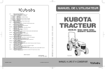
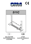
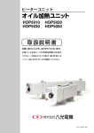
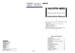
3. SAFETY INSTRUCTIONS
®
5. OPERATION
WARNING
CAUTION : Failure to comply with a CAUTION may result in injury to the operator, or damage to the
items involved. Two examples are given below.
Please check to make sure that all items listed
below are included in the package.
Hexagon wrench
Instruction manual
1
1
Solder pot
Spatula
Hexagon wrench
J-shaped waste collector
Power cord
Display
UP
Solder pot mounting
screws (both sides)
DO
WN
When the power is ON, the temperature of the melted solder in the solder pot is approximately
450°C/842°F. Before changing the solder pot, be sure to unplug the power cord and let the solder
and the unit cool to room temperature.
Observe the following precautions to ensure safety.
CAUTION
The molten solder in the solder pot is dangerous since it reaches about 450°C/842°F. The pot cover also
becomes a high temperature when the power is ON. Wrong handling may cause burns or fire. Be sure to
observe the following precautions.
Use this product on highly stable metal workbench. Never use it near paper or other flammable materials.
Inform others in the area that the product is hot and should not be touched.
Never put water in the solder pot as this will cause solder to spatter out of the solder pot.
Turn the power off when not in use, or left unattended.
Before changing parts or storing the unit, be sure to turn the power off and allow the unit to cool to room
temperature.
Observe the following precautions to prevent accidents or damage to the unit.
Do not use the HAKKO FX-301 for applications other than soldering.
Do not modify the HAKKO FX-301.
Use only genuine HAKKO replacement parts.
Do not allow the HAKKO FX-301 to become wet, or use it with wet hands.
Be sure the work area is well ventilated. Soldering produces smoke.
Do not do anything else that might be dangerous.
Power switch
Control buttons
UP
DOWN
● Display
The front panel of the HAKKO FX-301 soldering pot
has the following controls:
NOTE:
The display blinks when the power is turned
ON or when settings are changed. This blinking occurs because the temperature control is
in progress. The current temperature will be
displayed in a short time.
- Increases the value in the appropriate display
window.
- decreases the value in the appropriate display
window.
- Holding down the button for one second or
more will enter into the temperature setting
mode. If the button is otherwise pressed for
only less than one second, the current set
temperature will remain displayed. In the input
mode, establish the entered value and exist
the data input mode.
- Holding down the button for one second or
more will enter into the offset input mode. If
the button is otherwise pressed for only less
than one second, the current offset value will
remain displayed.
Fuse
2. SPECIFICATIONS
4. INTIAL SETUP
50 × 50 Square
100V - 200W, 110V - 260W, 120V - 310W, 220V - 240W, 230V - 260W, 240V - 280W
Temperature range
200 - 450°C (400 ~ 840°F)
200 - 380°C (400 ~ 720°F)
Solder pot dimensions
50 (W) × 50 (D) × 42 (H) mm (2.0 × 2.0 × 1.7 in.)
75 (W) × 75 (D) × 55 (H) mm (3.0 × 3.0 × 2.2 in.)
Molten solder capacity
0.85 kg (1.87 lb.)
1.2 kg (2.64 lb.)
Weight
1.7 kg (3.74 lb.)
6. PARAMETER SETTINGS
1. Install the J-shaped waste collector to the unit.
(Three-way installation is possible to meet your
operating needs.)
75 × 75 Square
Power consumption
2. Cut the solder sticks into small pieces and put
them in the solder pot.
(w/o solder and cord)
Outer dimensions
3. The temperature control is started, causing the
temperature to increase.
WARNING
Thank your for purchasing the HAKKO FX-301 soldering pot.
Please read this manual before operating the HAKKO FX-301.
Keep this manual readily accessible for reference.
1. PACKING LIST AND PART NAMES
1. Turn the power switch ON.
2. The temperature set at factory is displayed.
*The temperature was set to 350°C at factory.
WARNING: Failure to comply with a WARNING may result in serious injury or death.
Instruction Manual
1
1
1
Operation
Warnings, cautions and notes are placed at critical points in this manual to direct the operator’s
attention to significant items. They are defined as follows:
SOLDERING POT
Unit
Spatula
J-shaped waste collector
Display and operation
3. Plug the power cord into a grounded wall socket.
143 (W) × 100 (H) × 220 (D) mm (5.6 × 4.0 × 6.7 in.)
UP
DO
WN
* Only a 50 × 50 square solder pot is included in this product.
* The 75 × 75 square solder pot is an optinal part.
* Specifications and design are subject to change without notice.
CAUTION
Make sure the power switch is off before plugging
in the power plug.
This product is protected against electrostatic discharge.
Make sure this product is grounded before using.
Before changing the setting temperature
The HAKKO FX-301 comes from the factory with
the following values preset:
°C or °F temperature display
selection
1C
°C
Setting a solder type
Setting the solder pot type
Setting the timer
21
31
40
Sn-Pb (Tin an lead)
50 × 50 square
OFF or disabled
● Entering the parameters
1. °C or °F temperature display selection
2. Setting a solder type
Once a solder type close to the applicable one
as shown in the right side, the temperature control will be performed for that solder type.
The HAKKO FX-301 has the following four parameters:
1) °C or °F temperature display selection
2) Setting a solder type
3) Setting the solder pot type
4) Setting the timer
Once you enter the parameter setting mode, the
setting sequence will start in the following order. After all the parameters have been set, the displayed
temperature setting starts blinking and the temperature of the solder pot starts rising.
1. Turn the power switch OFF.
2. Press and hold down the
and
buttons simultaneously, and then turn the power switch
ON.
3. When you enter the parameter setting mode,
is displayed.
4. Press the
or
button to select
for °C
or
for °F.
After checking the displayed selection, press the
button.
After establishing the temperature unit to use,
enter the solder type selection mode.
Press the
or
button to select the number corresponding to your solder type as follows:
Sn-Pb (Tin an lead)
Sn-Ag-Cu (Tin, silver, and copper)
Sn-Cu (Tin and copper)
Sn (Tin)
HEAD OFFICE
After checking the displayed selection, press the
button.
TEL:+81-6-6561-3225 FAX:+81-6-6561-8466
http://www.hakko.com E-mail:[email protected]
Please access to the following address for the other Sales affiliates.
http://www.hakko.com/address
Copyright © 2005 HAKKO Corporation. All Rights Reserved.
2005.2
MA01375JZ050202
NOTE:
The solder types are listed for only rough classification. Select the closest one to your solder type.
6. PARAMETER SETTINGS
3. Setting the solder pot type
In the HAKKO FX-301 package, the size of the
solder pot is 50 × 50 square. The 75 × 75 square
solder pot is available to order for the requirement of your work.
8. IN CASE THE DISPLAY AND THE ACTUAL TEMPERATURE IS DEFFERENT
Set the size of the solder pot that you will use.
50 × 50 Square: Setting range of temperatures 200 - 450°C/400 - 840°F
for OFF or disabled
for a value between 10 and 9990 hours
Select the displayed
and then press the
button. You will proceed to enter the time to set.
Enter a desired time value.
Time can be set in units of 10 hours in a range between
and
(10 and 9,990 hours). After
entering the time value, press the
button.
NOTE:
After the set time has passed,
will be displayed, the alarm will start sounding, and then the
heater for the solder pot will be turned OFF. To
reset the alarm and others, turn OFF the power
switch and then immediately turn it ON again.
The timer will be reset to the above time setting.After the set time has passed, the heater for
the solder pot will be turned OFF.
● How to change and reset
Changing the time
Resetting the time
Enter the value between
001~999.
The HAKKO FX-301 is preset at 350°C at the factory.
Example: 350°C to 400°C
1. Check that the displayed value is 350°C.
Press the
button for one second or more. The
hundreds digit will start blinking, indicating the
unit is in the temperature setting mode.
Range of values:
°C... -70 to +70°C
°F ... -158 to +158°F
Example:
When the set temperature is 400°C and the actual solder temperature in the solder pot is
350°C; The difference between the two is
+50°C . Therefore, enter 050 instead of the current offset value.
When the temperature of solder reaches the set
value, the buzzer sounds. About 5 to 10 minutes
later, measure the temperature of solder. If the
measured value is different from the displayed temperature, match them with each other by entering
an offset.
Press the
or
button.
Changing the solder pot
3. Entering the tens digit
Press the
or
button to set the desired figure. When the desired figure is displayed, press
the
button to enter. The unit's digit will begin
to blink.
4. Entering the unit's digit
Press the
or
button to set the desired figure. When the desired figure is displayed, press
the
button to enter. Now the setting has been
completed.
After the setting has been completed, the displayed
temperature starts blinking and the temperature in
the solder pot starts rising. The current temperature
will be displayed in a short time.
button
Press the
button
NOTE:
When measure the temperature of the solder, be
sure to measure at the same position.
16
1
5
5
DOW
N
button once.
Truss screw
M4 × 5 (12)
External tooth
lock washer
Nominal size 4 (2)
4
3
UP
DO
WN
WARNING
When the power is ON, the temperature of the
melted solder in the solder pot is approximately
450°C/842°F. Before changing the solder pot, be
sure to unplug the power cord and let the solder
and the unit cool to room temperature.
2. Pull out the solder pot.
3. Insert a new solder pot and then tighten the
screws on both sides.
9
11
6
CAUTION
Check that the solder pot has been locked
now. Otherwise, the temperature may not increase properly.
10
Pan head screw
M3 × 4 (12)
14
3
Plain washer
M3 (4)
3
1. Loosen the screws on both sides of the unit.
(Fig. 1)
Pan head screw
with spring, plain
washer
M3 × 6 (2)
Pan head screw
M3 × 8 (1)
18
Fig. 2
DOW
N
Fig. 3
UP
N
Fig. 4
4. Slide the front panel frontward, remove the connector (Fig. 4) on the connector circuit board, and then
pull out the unit of the heating element (Fig. 5).
5. Insert a new heater unit and then install it by reversing the above steps.
External tooth
lock washer
Nominal size 3 (1)
External tooth
lock washer
Nominal size 4 (1)
● FX-301 Soldering pot
Item No.
①
②
③
④
⑤
UP
DOW
7
3. Remove the setscrews (6 pieces) on the unit.
(Fig. 3)
UP
N
Fig. 5
After finishing the maintenance, measure the temperature of solder. If the measured value is different
from the display temperature, enter an offset.
⑥
⑦
10. ERROR MESSAGES
● Sensor Error
Pan head screw
with spring washer
M4 × 6 (1)
8
2. Pull out the solder pot. (Fig. 2)
NOTE:
For the 50 × 50 square pot, the setting range of
temperatures is between 200 - 450°C/400 - 840°F.
For the 75 × 75 square pot, the setting range of
temperatures is between 200 - 380°C/400 - 720°F.
Pan head screw
M3 × 10 (4)
NOTE:
Removal is unnecessary.
Fig. 1
DOW
Pan head screw with
spring, plain washer
M4 × 8 (4)
External tooth
lock washer
Nominal size 4 (1)
12
DOW
N
Press the
17
2
UP
button once.
Truss screw
M3 × 8 (4)
13
NOTE:
Removal is unnecessary.
UP
button.
Press the
Is the power cord and/or the connection plug disconnected?
Connect it.
Is the fuse blown?
Investigate why the fuse blew and then replace the fuse. If the
cause can not be determined, replace the fuse. If the fuse blows
again, send the unit in for repair.
12. PARTS LIST
1. Using the hexagon wrench (provided with the
HAKKO FX-301) to loosen the screws on both
sides of the unit.
button once.
or
Press the
button.
:
:
:
:
WARNING
DOW
N
Press the
or
CHECK
ACTION
CHECK
ACTION
Unless otherwise directed, carry out these procedures after turning the power switch OFF,
unplugging the power plug and waiting for both the unit and the solder to sufficiently cool down.
UP
2. Entering the hundreds digit
Press the
or
button to set the desired figure. When the desired figure is displayed, press
the
button to enter. The tens digit will begin to
blink.
Press the
l The unit does not operate when the
power switch is turned on.
9. MAINTENANCE
Replacing the heating element
Press the
button
Button bolt
M4 × 35 (2)
CAUTION
After changing the solder pot, measure the temperature again. If the measured value is different
from the displayed temperature, enter an offset.
Press the
button and
hold for one second.
Press the
WARNING
• Before checking the inside of the FX-301 or replacing parts, be sure to disconnect the power
plug.
15
Once you can check the display and the measured
temperature, all the settings are finished.
In case of resetting the time
(in the middle of setting the
time.), please change to the
different value once, and enter the desired value.
7. CHANGING THE TEMPERATURE SETTING
● Changing the temperature setting
Press the
button and
hold for one second.
The offset value was set to 0°C at factory.
75 × 75 Square: Setting range of temperatures 200 - 380°C /400 - 720°F
Press the
or
to select the number corresponding to your solder pot size as shown above.
After checking the displayed selection, press the
button.
4. Setting the timer
It will be able to check the present addition time
by pressing the
button.
● Entering offset value
11. TROUBLE SHOOTING GUIDE
There is the possibility that a failure has occurred in
the sensor circuit. The power is shut down with the
buzzer sounding continuously.
⑧
⑨
⑩
⑪
⑫
Part No.
B2917
B2918
B2916
B2920
B2921
B2705
B2468
B2922
B3045
B2924
B2925
B2926
B2927
B2928
B1084
B1134
B1795
B1796
⑬
B2913
B2914
Part Name
Cover
Overflow tray
Heat insulator
Front panel
P.W.B.
Fuse/125V-5A
Fuse/125V-5A
Fuse/250V-5A
Fuse/250V-5A
Transformer
Transformer
Chassis
Solder pot support
Solder pot tray
Power switch
Fuse holder
Power cord, 3 wired
cord & American plug
Power cord, 3 wired
cord but no plug
Power cord, 3 wired
cord & BS plug
Power cord, 3 wired
cord & Chinese plug
Specifications
With membrane sheet
For temperature
control, connector
100 - 110V
120V
220 - 240V
220 - 240V KTL, CE
100 - 120V
220 - 240V
With rubber feet
Item No.
⑬
230V
230V India
220V China
B1798
B3046
Part Name
Power cord, 3 wired
cord & European plug
Power cord, 3 wired
cord & Australian plug
Power cord, 3 wired
cord & BS plug
Specifications
220V KTL, CE
240V
230V UK
● Replacement parts
Item No.
⑭
⑮
⑯
⑰
⑱
100 - 220V
Part No.
B1797
Part No.
A1515
A1516
A1517
B2919
B2932
B1417
Part Name
Heating element
Heating element
Solder pot
J-shaped waste collector
Spatula
Hexagon wrench
Specifications
100 - 120V
220 - 240V
50 × 50 × 42(mm)/1.97
× 1.97 × 1.65(in.)
2.5mm
● Optional parts
Part No.
A1518
Part Name
Solder pot
Specifications
75 × 75 × 55(mm)/2.95
× 2.95 × 2.17(in.)