1
&7
and
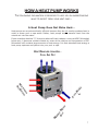
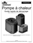
Pool and Spa
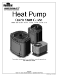
Heat Pump
Owner’s Manual
and
Installation Guide
PN: LTP0051
6/1/05
Models:
100, 120, & 155
HEATING ONLY
and
HEATING - COOLING
Additional Labels:
APS
Fox Smart
South Beach
Tropez
ATTENTION INSTALLER:
THIS DOCUMENT IS PURCHASER’S PROPERTY AND IS TO REMAIN WITH THE HEAT PUMP OWNER
1/7/041
1-800-786-7751
NOTES
___________________________________________________________________________________
__________________________________________________________________________________
___________________________________________________________________________________
_________________________________________________________________________________
_________________________________________________________________________________
_________________________________________________________________________________
___________________________________________________________________________________
__________________________________________________________________________________
___________________________________________________________________________________
_________________________________________________________________________________
__________________________________________________________________________________
________________________________________________________________________________________
___________________________________________________________________________________
____________________________________________________________________________________
_________________________________________________________________________________
__________________________________________________________________________________
_________________________________________________________________________________
__________________________________________________________________________________
2
__________________________________________________________________________________
TABLE OF CONTENTS
WELCOME TO THE TEAM ---------------------------------------------- 5
IMPORTANT FEATURES OF YOUR NEW HEAT PUMP ------------------ 6
HOW A HEAT PUMP WORKS ------------------------------------------ 7
SAFETY INFORMATION------------------------------------------------ 8
QUICK START & STOP ------------------------------------------------- 10
HEATER CONTROLS --------------------------------------------------- 12
Control Panel Layout ----------------------------------------------- 12
Buttons, Lights, and Display -------------------------------------- 12
Operational & Programming Codes -------------------------------- 13
Owner-Level Programming (complete) --------------------------- 14
MAINTENANCE AND GENERAL OPERATION -------------------------- 18
General Maintenance----------------------------------------------- 18
Safety During Cleaning Operations ------------------------------- 18
Maintaining Proper Water Flow ------------------------------------ 19
Controlling Water Chemistry -------------------------------------- 19
Controlling Irrigation and Storm Water Run Off ------------------ 20
Maintaining Clearances Around Heater --------------------------- 20
(Continued
on Next Page)
3
TABLE OF CONTENTS
(CONTINUED)
MAINTENANCE AND GENERAL OPERATION...CONTINUED:
Heating Tips -------------------------------------------------------- 21
- Heating in Cooler Weather -------------------------------------- 21
Pool/Spa Blankets----------------------------------------------- 21
Pool & Spa Combination Heating ------------------------------- 21
Spa Set-Back Option ------------------------------------------- 21
Calculating Initial Heating Time ----------------------------------- 22
Seasonal Use & Shut Down ---------------------------------------- 23
- (Use) During the Swim Season -------------------------------- 23
- Freeze Protection and Winterizing Requirements -------------- 23
- Winterizing Procedure ------------------------------------------ 24
AquaCal Preventive Maintenance Program ------------------------ 25
TROUBLESHOOTING (No Op, No heat, Water from Unit) ------------ 26
Troubleshooting Flowcharts ----------------------------------------27
DEALER-SPECIFIC INFORMATION (Installation & Set Up) --------- 31
Dealer-Specific Table of Contents --------------------------------- 32
CONTACTING THE FACTORY ------------------------------------------ 58
4
Welcome
to the
Team
Dear Owner:
C
ongratulations on your wise decision to make an AquaCal heat pump part of
your home. Since 1981, AquaCal has maintained the worldwide lead in the
manufacture of swimming pool & spa heat pumps. Your new heat pump is not
only a great investment, but also the most cost effective method available for
heating pools and spas. For example, your heat pump is up to 400% more
efficient than gas, and, when compared
to electric resistance heat, your heat
pump is nearly 600% more effective. You
can rest assured your new heat pump is
of the highest quality and efficiency, and
is designed and built to provide years of
trouble-free operation.
Moreover, should you decide you would
like AquaCal to provide regular inspection
and maintenance of your heat pump—
which we do recommend—you will find
AquaCal’s factory-trained service staff is
the largest and most-qualified in the pool
& spa heat pump industry.
“You can rest assured
knowing your new heat
pump is of the highest
quality and efficiency,
and is designed and
built to provide years
of trouble-free
operation.”
5
Important Features of Your
New Heat Pump
ThermoLink® Heat Exchanger
The heart of your heat pump is the patented ThermoLink heat exchanger. The primary
cause of premature heat pump demise is the failure of the heat exchanger. Ordinary
heat exchangers are made from a cupronickel alloy. This cupronickel material is susceptible to attack from the sanitizers used in pools and spas, and from other related water
chemistry conditions. Once the heat exchanger fails, the heat pump is ruined. The
ThermoLink heat exchanger tube is made from titanium, and is virtually impervious to
water chemistry damage.
Scroll Compressor
50% fewer moving parts than standard piston-type compressors. This equates to
much improved reliability and improved efficiency. Scroll compressors are also much
quieter in operation than piston-type compressors.
Digital Controller
Digitally-based microprocessor, controls water temperature to within 1º Fahrenheit of
set point. Controller also permits user to predefine different pool and spa water temperatures, and to prevent tampering by locking out controls via a pass code.
Heat & Cool Capability*
Puts you in full control, year round ...Warms your pool or spa with the reliability and
efficiency of our other heat pumps, but, with the flip of a switch, can also cool your pool
or spa to refreshing temperatures during the hot summer months. For cooler climates,
Icebreaker® heat pumps offer unique advantages over passive defrost models. Please
read more below...
Hot Gas Defrost*
Your Icebreaker® heat pump is uniquely equipped for active defrost. Active defrost
involves directing hot refrigerant gas to the heat collector, melting accumulated ice
away in a matter of a few minutes—then right back to heating. Standard heat pumps
may remain “off in defrost” for extended periods during very cold weather. Because of
its ability to continue to operate even during freezing weather, your Icebreaker extends
the swimming season longer than any other heat pump.
Corrosion-Proof Cabinet
The cabinet, being made from resilient, UV-Protected ABS material, can never rust, fade
or corrode. You can expect the cabinet to retain a like-new appearance with only an
occasional wash down and—if so desired—a quick waxing.
*Icebreaker
®
Models Only
PLEASE READ FURTHER TO BECOME FAMILIAR WITH ALL THE FEATURES, THE
SAFE OPERATION, AND THE CARE OF YOUR NEW HEAT PUMP.
6
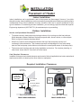
HOW A HEAT PUMP WORKS
THE FOLLOWING EXPLANATION IS PROVIDED TO HELP YOU IN UNDERSTANDING
WHAT TO EXPECT FROM YOUR HEAT PUMP…
A Heat Pump Does Not Make Heat…
Heat pumps are so extraordinarily efficient because they do not need to produce heat in
order to warm pool or spa water. Rather, heat pumps simply transfer heat from the
outside air into the water.
If one considers absolute “0”–the point where all heat is absent–occurs at 459º Fahrenheit
below zero, it becomes evident outside air–even at the relative cool temperature of 55º
Fahrenheit–still contains large amounts of heat energy. It is that abundant heat energy a
heat pump captures and places into your pool or spa.
HEAT REMOVED FROM AIR...
COOL AIR OUT
R
AT
E
IN
UT
W
O
AR
M
ED
W
AT
E
R
CO
OL
W
N
DE
LA TERS
EN
R
AT
HE
AI
7
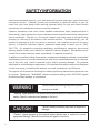
SAFETY INFORMATION
Used and maintained properly, your heat pump will provide year-upon-year of safe and
economical service. However, as with any mechanical or electrical device, to get the
most from your heat pump–while insuring personal safety for you and others–certain
operational and maintenance factors must be observed.
Likewise, excepting a few minor owner-capable maintenance items (explained later in
this manual), repair and service of your heat pump must be performed only by experienced
service personnel. Should you, the owner, suspect your heat pump is not performing
properly, by referring to the section in this manual entitled: "Troubleshooting", you will
be able to determine if a call for service is required. Your installer can be one source of
service, or AquaCal Customer Support personnel stand ready to assist you at: (800)
786-7751. For questions concerning installation, modifications, operation, service and
upkeep, please contact your installer or AquaCal Customer Support. Warranties may be
voided if the heater has been used, maintained, or repaired improperly.
In addition to possible voiding of warranties: unapproved installation methods, nonstandard
modifications, poor or incorrect maintenance, service by unqualified personnel, or improper
use of this unit, may result in personal injury and/or property damage. For personal
safety and to avoid damage to equipment, it is important that safety instructions displayed
on the heat pump, and within this manual, are read, understood, and followed.
Throughout this manual the following two safety signals are placed where particular care
is required. Please note "WARNING" relates to personal safety, while "CAUTION" signals
promote avoiding damage to equipment.
WARNING !
Failure to heed the following may result in permanent injury or death.
“Warning” signal appears in this manual where special attention is required for personal
safety. (Specific instructions will appear in this box.)
CAUTION !
Failure to heed the following may result in equipment
damage.
“Caution” signal appears in this manual where special care is required to avoid
equipment damage. (Specific instructions will appear in this box.)
8
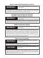
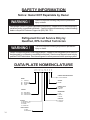
Notice: Heater NOT Repairable by Owner
WARNING !
Failure to heed the following may result in permanent
injury or death.
Heat pumps contain no owner-repairable components. Repairs must not be attempted
by untrained and/or unqualified individuals. If service is deemed necessary, contact
installing dealer or AquaCal Customer Support at (800) 786-7751.
Refrigerant Circuit Service Only by
Qualified, EPA Certified Technician
WARNING !
Failure to heed the following may result in permanent
injury or death.
Heater contains refrigerant under pressure. Repairs to the refrigerant circuit must not be
attempted by untrained and/or unqualified individuals. Service must be performed only by
qualified HVAC technicians. Recover refrigerant to relieve pressure before opening system.
Water Temperature Safety
WARNING !
Failure to heed the following may result in permanent
injury or death.
Prolonged immersion in water warmer than normal body temperature may cause a condition known as HYPERTHERMIA. The symptoms of hyperthermia include: unawareness of
impending hazard, failure to perceive heat, failure to recognize the need to exit the spa,
and unconsciousness. The use of alcohol, drugs, or medication can greatly increase the
risk of fatal hyperthermia. In addition, persons having an adverse medical history, or pregnant women, should consult a physician before using a hot tub or spa. Children and the
extreme elderly should be supervised by a responsible adult.
Water Chemistry Safety
WARNING !
Failure to heed the following may result in permanent
injury or death.
Improper water chemistry can present a serious health hazard. To avoid possible hazards,
maintain Pool/Spa water per standards detailed later in this manual..
CAUTION !
Failure to heed the following can result in damage to
equipment.
While your heat pump’s titanium-based heat exchanger provides nearly impervious
protection against poor water chemistry, improper water chemistry may cause expensive
damage to pump, filter, pool shell, etc. To avoid equipment damage, maintain Pool/Spa
water per standards detailed later in this manual.
9
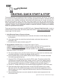
Getting Started
HEATING- QUICK START & STOP
This brief information is provided as an aide to installers, service personnel, and owners. The intent of
this section is to provide rapid access to (only) very basic operational information. Individuals who will
be routinely using, installing, maintaining, and servicing this heat pump, are strongly encouraged to
read this entire manual. Herein, the terms: Heat Pump, Heater, and Unit are used synonymously.
These instructions are intended for local control of a heat pump, independent of an external
controller. Owners: if your installation includes an external controller, contact your installing
dealer for operational instructions.
These are instructions to quick-start in the HEATING mode...Owners of Heat-Cool units, in order to
utilize all features of their heater, will certainly want to also refer to: Owner Level Programming, beginning on page-14 of this manual.
1. Verify Electrical Power is Present at Heater:
A. Ensure that the unit has electrical power connected; the heater controller display should
be illuminated;
B. If the display is blank, be certain the electrical breaker, and heater disconnect, are
switched to “ON”;
C. For now, leave the water circulation pump OFF.
2. Set the Heater Controls (Refer to Control Panel Layout, Pg-12):
OWNER- If heater is connected to a Call-Flex controller, also see Call-Flex programming
located in Owner Level Programming, beginning on page-14 of this manual.
INSTALLER- Is heater connected to an external controller? See: Dealer-Specific Instructions,
beginning on page-31 this manual.
A. The owner settings can be set without water flowing. Once the heater has electrical power
connected, with water not flowing, the display should read FLO;
B. Press the MODE button until the HEAT (HEA) indication displays. This action will enable
the remaining programming keys;
C. Using the POOL / SPA selector key, select the POOL mode. The chosen mode will be
verified by an illuminated indicator light, located on the left side of the display, showing
that the POOL control has been selected (If heating just a spa, using the DOWN arrow
key, lower the POOL temperature until OFF is displayed; then proceed to Step-E. ).
D. Use the UP / DOWN arrow keys to set the desired water temperature for the POOL water;
E. If the heat pump will be used to heat a spa, use the POOL/SPA selector key to select
SPA, then use the UP / DOWN arrow keys to set the desired water temperature for the
SPA (If heating just a POOL, using the DOWN arrow key, lower the SPA temperature until
OFF is displayed.);
F. The heat pump controls are now set to maintain the desired water temperature for the
POOL and/or SPA.
(Quick-Start & Stop Continued Next Page)
10
HEATING-QUICK START & STOP (continued):
3. To Begin Heating:
A. Verify MODE is set to: HEAT; then, depending on which body of water is to be heated, use the
POOL / SPA selector key to select POOL or SPA ;
B. Position external water valves appropriately to flow water to & from the body of water and
through the heater;
C. Start the water pump...Within 4-minutes, depending on the status of the controller’s internal
time delay, the heater will start. The selected body of water will be brought to temperature and
maintained per the setting determined previously in: “Set the Heater Controls”;
D. In operation, whenever the actual (displayed) water temperature falls below the desired set
point, after an initial time delay of 4-minutes, the unit will begin heating .
NOTE: THE HEAT CONTROLLER INCORPORATES AN ANTI-SHORT CYCLE TIME DELAY. SHOULD OPERATION BE
INTERRUPTED, RESTART WILL BE DELAYED BY APPROXIMATELY 4-MINUTES.
4. Program Filter Pump Run Time:
Most pool/spa systems utilize a timer or multifunction controller to manage filter pump run
times.” If your system incorporates such a device, follow the instructions below:
A. It will be necessary to allow the filter pump to run continuously until the water has reached the
desired temperature. If a timer controls the pool filter pump, it will be necessary to override
the timer to allow 24-hr. operation.
B. Once the desired temperature has been obtained (2-4 days), reset the pump control device.
Colder months require longer running times–generally eight to twelve hours/day.
C. A heat pump can only operate when the filter pump is running. Therefore, it may be
necessary–during cooler weather–to extend the water pump’s hours of daily operation.
The increased run time is necessary in order to keep up with increased, weather-related
heat losses.
5. Continuous Usage and Water Around Heater:
Condensation... After the heat pump has been operating for some time, water may be observed
surrounding the heater. The moisture seen is condensation produced as a by-product of
transferring heat from the air into the pool or spa water. Quantities of 6-8 gallons of water
produced per hour are common if the air humidity is high. Conversely, a low humidity condition
may result in no condensation being produced. (To troubleshoot, see page-26, “Water Coming
from the Heat Pump.”)
6. To Stop the Heat Pump:
A. Select: OFF via the MODE selector. This method of shut down preserves the controller
settings;
B. An interruption of water flow–such as when a pump timer is in control–will, also, cease heat
pump operation.
(End...Quick-Start & Stop)
11
HEATER CONTROLS
Control Panel Layout
(APPEARANCE VARIES BY MODEL)
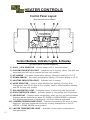
Control Buttons, Indicator Lights, & Display
(AS INDICATED BY CIRCLED NUMBERS)
1) POOL / SPA SELECTOR – Selects either pool or spa thermostat.
2) COOLING INDICATOR LIGHT – Indicates unit is cooling. (Note: This light and
associated text will not be present on heat only models)
3) UP ARROW – Increases temperature setting. (Maximum setting is 104 oF)
4) DOWN ARROW – Decreases temperature setting. (Minimum setting is 45 oF)
5) HEATING INDICATOR LIGHT – Indicates unit is heating.
6) MODE SELECTOR – Used to select between the Heating, Cooling, AutoChangeover, and Off for Heat & Cool models. Used to select between Heating
and Off for heat-only models.
7) SPA INDICATOR LIGHT – Indicates heater is referencing spa thermostat.
8) POOL INDICATOR LIGHT – Indicates heater is referencing pool thermostat.
9) LED DISPLAY – Displays water temperature when no keys are being pressed.
Displays desired temperature when UP ARROW or DOWN ARROW is pressed.
Also displays operational, programming, and fault codes as applicable.
10) DESIRED TEMPERATURE LIGHT – Indicates temperature set point is being
displayed. Indicates temperature set point is being changed due to the UP
ARROW or DOWN ARROW being pressed.
11) WATER TEMPERATURE LIGHT – Indicates current water temperature is
being displayed.
12
HEATER CONTROLS...continued
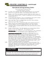
Operational & Programming Codes
THE FOLLOWING CODES WILL BE DISPLAYED AS PART
OF THE NORMAL OPERATION OF THE HEATER:
FLO..... No Water Flow Detected. This code appears whenever the circulating
pump is off, or when the heater is not receiving correct water flow.
OFF..... System is Off. This code appears whenever heater has been turned off
via the mode selector button, or when the temperature set point has been
lowered below 45 oF.
CFI...... Celsius/Fahrenheit Selection. This is a programming entry point to select
in which format the water temperature will be displayed.
ULC.....User Lock Code. This is a programming entry point; when activated,
steps to the next menu level: ELC.
ELC..... Enter Lock Code. This a programming entry point; permits end user to
select a secret code, thereby limiting access to the owner settings.
CFO.....Call Flex Options. This is a programming entry point; when used in
conjunction with a AquaCal Call/Flex add on kit, permits the use of CALL
or FLEX options.
FS....... Heater in Defrost Mode. This code appears as a normal display during
periods of lower air temperatures. Two possibilities follow:
Heat-Only Units: Fan continues to run and compressor is off. Compressor
will restart when air coil temperature rises to approximately 38°F.
Heat-Cooling (reversing) Units (Applicable in Heat Mode Only): if a
defrost cycle is necessary, the unit’s reversing valve will be activated.
While the reversing valve is activated, the fan operation will be
suspended to permit maximum heating of the air-coil. The reverse-cycle
will continue until the air-coil reaches a set temperature, or until 4-Minutes
has elapsed. Upon completion of the defrost cycle, the reversing valve
will be deactivated; normal fan and heating operation will resume. During
hot-gas defrost cycles, the compressor will not deactivate; rather, it will
continue in operation throughout the sequence.
LOC.....This is a Service Entry Point (not intended for use by the owner). The
[LOC] code permits service personal to enter a factory code for access to
adjustable calibration and site-dependant setup parameters. Service
adjustments are available to authorized installation and service
personnel, only.
CAUTION !
Failure to heed the following may result in equipment damage
and voiding of manufacturer’s warranty.
Heat pumps contain no owner-serviceable components. Owner-initiated adjustments, beyond
the controller “LOC” code, must not be attempted. If adjustments are deemed necessary, the
owner should contact installing dealer or AquaCal Customer Support at (800) 786-7751.
13
HEATER CONTROLS...continued
Start Up & Setting Operating Controls
Owner-Level Programming Instructions (Complete)
Covered within this section are features and settings typically accessed first by the installer, and
then remaining accessible by the end user (owner). These features reside at the Level-1 access
point within the microprocessor.
1. Applying Power to The Controller:
A. When power is first applied, the controller performs a lamp test and the display will read
[888]. Following [888] the software version will display briefly;
B. The control will then display the actual water temperature, provided the circulating pump is
operating, and adequate water is flowing through the heater;
C. If the pool-circulating pump is off, the control will display: [FLO]. This code message
indicates no (or insufficient) water is being circulated through the heat pump.
2. Starting the Heat Pump:
A. Once electrical power is supplied to the heat pump, sufficient water is circulating, and the
heater controller has successfully completed its self-test, the heater is ready to operate;
B. The heat pump is shipped with the controller [MODE] function set to “OFF”. There are two
ways to switch the heat pump OFF: First Method- One of the functions of the [MODE]
button is “OFF”. Second Method- The thermostat set point can be lowered to a position
below the minimum temperature setting (45oF); this action will cause the display to read
“OFF”. To switch the unit ON, first use the mode button to select the HEAT mode— for Heat
Only models—or, if the heat pump is a Heat and Cool model, use the mode button to select
one of the following modes: HEAT, COOL, or ACH (Auto-changer over). In the [OFF] mode,
the actual water temperature will be displayed as long as the circulating pump is operational
and correct water flow is present. In the event water is not circulating through the heat pump
(or flow is insufficient), the controller will display the [FLO] (No Water Flow) code message.
C. Using the UP ARROW key, increase the desired temperature until it exceeds the value of the
actual temperature displayed. (Note: See # “8,” later in this section, if “000” is displayed upon
pressing either the up or down arrow keys.) Once the desired temperature has been
entered, the display will read the actual temperature and the heat pump will start to operate.
Both the compressor and the fan must be operating before the “Heating” LED will illuminate.
(Note: When MODE function is OFF, the current water temperature will be displayed; no
functions, values, or programming will be available for adjustment.)
3. Turning The Heat Pump Off:
A. Method 1: using the [MODE] key, depress the key until the display reads “OFF” The
heater will shut off and remain off until the [MODE] key is used the select an operational
mode. This is the preferred method for shutting off the heat pump.
B. Method 2: using the DOWN key, depress the key until the desired water temperature
reaches 45oF (minimum setting); then, depress the DOWN key one more time, causing the
display to read “OFF”. This method is typically used in conjunction with 2-wire external
controllers; these controllers are equipped with their own thermostats.
(Continued
14
on Next Page)
HEATER CONTROLS...continued
Start Up & Setting Operating Controls
Owner-Level Programming Instructions...continued:
4. Selecting Pool/Spa Thermostat Settings:
A. Depress the [POOL/SPA] key to toggle between the pool and the spa temperature set
points.
B. The pool/spa LED indicator lights, located to the left of the temperature display, will confirm
the selected set point.
5. Changing The Pool Temperature Set Point:
A. Using the [POOL/SPA] key, select the POOL temperature set point. The pool set point
indicator light will confirm the selection.
B. The pool temperature set point is adjustable from a minimum of 45oF to a maximum of
104oF. Depressing the [UP ARROW] key will raise the set point 1-degree for every push of
the button. Depressing the [DOWN ARROW] key will lower the set point 1-degree for every
push of the button.
6. Changing The Spa Temperature Set Point:
A. Using the [POOL/SPA] key, select the SPA temperature set point. The spa set point indicator
light will confirm the selection.
B. The spa temperature set point is adjustable from a minimum of 45oF to a maximum of
104oF. Depressing the [UP ARROW] key will raise the set point 1-degree for every push of
the button. Depressing the [DOWN ARROW] key will lower the set point 1-degree for every
push of the button.
7. Selecting Between oF and oC:
A. Simultaneously depress and hold both the [UP ARROW] and [DOWN ARROW] keys until
[CF1] (Celsius / Fahrenheit) code appears.
B. With the [CF1] code displayed, pressing the [UP ARROW] or [DOWN ARROW] keys will
change the selection code to either “0” or “1”. Select “1” for Fahrenheit temperature display,
or “0” for Celsius temperature display. Once the desired temperature display mode has
been selected, not pressing any buttons for 15-seconds will allow the controller to save the
selection and return to the normal operating mode. Pressing the {POOL/SPA] key will also
save the selection and step to the next menu parameter: [ULC] (User Lock Code).
8. User Lock Code Option [ULC]:
This Option Explained:
Heat pumps are shipped from the factory with the [ULC] option disabled. Enabling the [ULC]
function permits the heat pump owner to restrict access to the unit’s controls. With the [ULC]
function enabled, unless the correct ULC code number is entered, changes to Level-1
programming are not possible. (I.e.: Altering temperature set points, Pool/Spa selection, C/F
display changes, etc., will not be possible). The [ULC] option can be thought of as an electronic
lockable cover for the controls.
(Continued
on Next Page)
15
HEATER CONTROLS...continued
Start Up & Setting Operating Controls
Owner-Level Programming Instructions...continued:
8. User Lock Code Option [ULC]...continued:
A. Selecting UCL Option:
1) Depress either the UP or DOWN ARROW keys; if “LOC” is momentarily displayed
flowed by “0”, the ULC feature is enabled. If “0” displays proceed to “6)” of this section;
otherwise, see number “2” below.
2) Simultaneously depress and hold both the [UP ARROW] and [DOWN ARROW] keys
until [CF1] (Celsius / Fahrenheit) code appears.
3) Depress the [POOL/SPA] key once to display [ULC].
4) With [ULC] displayed, pressing either the Up or Down Arrow key will display either “1” or
“0”. Selecting “0” will allow the keypad to remain unlocked. Selecting “1” will enable the
User Lock Code option. Then to enter a lock code number, press the [POOL/SPA] key
once to display [ELC] (Enter Lock Code).
5) With [ELC] displayed, use the Up or Down arrow keys to select a lock code. The code
can be any number from “00” to “99”. The factory set lock code is “0”. Not pressing any
buttons for 15-seconds will allow the controller to save the selection and return to the
normal operating mode. Pressing the {POOL/SPA] key will also save the selection, and
will step the controller to the next menu parameter: [CFO] (Call Flex Options).
6) Once the ULC option has been enabled, depressing any key will momentarily display
“LOC” followed by “0” (prompting the entry of the correct lock code number). To gain
access to the controller:
a. Using the [UP ARROW] key, scroll to the correct lock code number, then;
b. Press the [POOL/SPA] key…Current water temperature will be displayed…Control
setting can now be viewed or changed as desired.
c. After a period of approximately four (4) minutes, during which time no buttons have
been pressed, the controller will automatically return to the locked mode. Provided
ULC selection is set to “1,” the controller will always fail-safe in the locked mode.
d. Without knowledge of the correct lock code, and with the ULC enabled, control
adjustments will not be possible. Be certain to record your lock code in a safe
place. The lock code may be changed any number of times by following the
instructions detailed in this section.
B. De-Activating the User Lock Code [ULC] function:
1) Following the instructions detailed previously at: “8, 6)”, press any key and enter the
user lock code number; then press the [POOL/SPA] key.
2) Immediately following the entry of the user lock code, simultaneously depress and hold
the [UP ARROW] and [DOWN ARROW] keys until the code [CF1] appears on the
display.
3) Then, use the [POOL/SPA] key to scroll to the [ULC] message; press the [DOWN
ARROW] key to change the display to “0”. This will disable the User lock function.
(ULC Continued
16
on Next Page)
HEATER CONTROLS...continued
Start Up & Setting Operating Controls
Owner-Level Programming Instructions...continued:
C. User Lock Code is Activated, but Pass Number is Not Known (“Back Door Entry”):
Note: Should the ULC option be enabled, and a lock code number other than the factory
default (0) be installed but is unknown, the following procedure may be followed to regain
controller programming access:
1) Simultaneously depress and hold the [POOL/SPA] and [UP ARROW] keys until the
display shows “888”. This operation will reset the controller to the factory default
settings.
2) When reset to the factory default settings the user lock code [ULC] is deactivated and
the user lock code number [ELC] is reset to “0”.
3) In addition, all other settings are returned to the factory defaults. If an external controller
is in use, contact AquaCal Technical Support Group (800-786-7751); ask for assistance
with re-configuring the controller for use with an external controller.
9. Selecting Call-Flex Pump Options [CFO]:
General Information:
The Call-Flex option automatically adjusts the run time of the water circulator pump, and heater,
based upon changing weather conditions. Without Call-Flex, as weather conditions grow
progressively cooler during winter months, or when unusually cold weather occurs, the run
duration of the circulator pump may require manual adjustments to permit the heater to maintain
or reattain desired water temperature (the water pump must be running in order for the heater to
operate). Likewise, without Call-Flex, one must remember to reset the pump run controls
following the cold weather event. The Call-Flex option greatly reduces the need for seasonal,
manually-made, pump run time adjustments. Call-Flex is a dealer-installed option that does not
come with every heater; if unsure, check with the installing dealer to determine if a call-flex kit
was part of the original installation. If Call-Flex was not part of the installation, and you would like
to have Call-Flex added, your dealer can do so...contact the installing dealer.
If the installation is equipped with the Call-Flex option, the following steps are used to control the
Call-Flex features:
A. Simultaneously depress and hold the [UP ARROW] and [DOWN ARROW] keys until the
display shows “CF1”. Depress the [POOL/SPA] key three times to scroll the display to
[CFO].
B. With the [CFO] (Call-Flex Options) code displayed, use the Up or Down keys to select “0” to
disable the Call Flex Options, “1” to enable the Call Option, or “2” to enable the Flex Option.
Not pressing any buttons for 15-seconds will allow the controller to save the selection and
return to the normal operating mode. Pressing the {POOL/SPA] key will also save the
selection, and will step the controller to the next menu parameter: [LOC] (Service Lock
Code).
C. For further information, please refer to Call-Flex installation instructions, shipped with the
Call-Flex kit. For additional copies of these instructions, contact the AquaCal Customer
Support (800-786-7751).
(End...Owner-Level Programming Instructions)
17
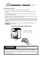
MAINTENANCE
&
OPERATIONAL RECOMMENDATIONS
The information in this section is written primarily for the Home Owner, but may also apply to servicing
dealers or HVAC service centers. This section contains information concerning planned maintenance,
proper water flow, maintaining proper clearances, as well as other vital information. Please read this
section now, and before calling AquaCal Customer Support (800-786-7751).
General Maintenance
Heat pumps should be inspected and maintained on an annual basis by a qualified swimming pool heat
pump specialist. Additionally, if the heat pump is located on the beach, or at a sea wall where salt spray
and sand can become detrimental factors, more frequent service may be necessary. For service plan
information, please see: Planned Maintenance Program, later in this section, and then contact AquaCal
Customer Support at: 800-786-7751.
While annual maintenance is recommended to maintain your warranty, if you choose not to participate
in the Planned Maintenance Program, rinsing the air coil regularly, and keeping the base of the unit
clear of leaves and debris is a necessity.
Should you as the owner desire to perform the coil rinsing and other cosmetic care of the heat pump,
please contact AquaCal Customer Support: 1-800-786-7751; request the document titled: “Appearance
Care for Air-Source Heat Pumps: Approved Method for Home Owners.”
Safety During Cleaning Operations
WARNING !
Failure to heed the following may result in permanent
injury or death.
POSSIBLE ELECTRIC SHOCK HAZARD . . . Should you decide to wash the heat pump
via water hose, disconnect all power to the pool equipment pad- including, but not limited
to: The heat pump, water pump, and any and all other electrical equipment. Do NOT spray
water directly into electrical components. Do NOT restore electrical power until such time
as all water has dried completely.
CAUTION !
Failure to heed the following may result in damage to
equipment.
Do not use a pressure cleaner to wash heat pump . . . . Damage to evaporator fins, as
well as other components, will result.
18
MAINTENANCE & OPERATION
(continued)
Maintain Proper Water Flow
•
It is important to operate and maintain the filter according to the manufacturer's specifications.
As a filter gets dirty, the water flow to the heat pump is reduced. The higher the pressure on the
filter gauge, the lower the flow rate.
•
Similar to a dirty filter, large amounts of debris in the pump basket can reduce water flow. Keep
basket free of debris.
•
Check for improper valve settings. A partially closed valve after the filter, or a full-open bypass
around the heater, will cause insufficient water flow through heater.
•
If the conditions listed above remain unresolved, the water flow through the heater may be
reduced to a point where internal safety devices shut the heater off.
•
Before calling for service, always check the filter, the pump basket, and water valve positions. If
the problem persists, please call AquaCal Customer Support at: (800)786-775.
Control Water Chemistry
•
IMPORTANT! All AquaCal heat pumps are engineered for exceptional durability and reliability.
And, this heater—being equipped with a titanium heat exchanger—will be nearly impervious to
water chemistry damage. However, the remainder of the pool/spa equipment may be
susceptible to damage from prolonged exposure to unbalanced water chemistry. Likewise,
bathers may be exposed to health risks if water chemistry is not properly maintained.
•
For the longevity of the entire pool/spa installation, and for the safety of bathers, it is strongly
recommended the water chemistry be checked regularly and maintained within proper norms.
Please see the table, below, for a complete listing of recommended water chemistry levels.
RECOMMENDED WATER CHEMISTRY STANDARDS
Chlorine . . . . . . . . . . . ........ . . .:
Bromine . . . . . . . . . . . . ........ . .:
pH . . . . . . . . . . . . . . . . . . ..........:
Total Alkalinity . . . . . . . . . ........:
Calcium Hardness . . . . . . . .....:
Total Dissolved Solids . . . . .....:
1.0 – 3.0 ppm in pools, 1.5 – 3.0 ppm in spas
2.0 – 4.0 ppm in pools, 3.0 – 5.0 ppm in spas
7.4 – 7.6 ppm in pools, 7.2 – 7.8 ppm in spas
80 – 140 ppm in pools, 80 – 120 ppm in spas
200 – 400 ppm in pools and spas
1,000 – 2,000 ppm in pools,
1,500 ppm above start-up TDS in spas
CAUTION- Pool/Spa Refinishing Operations
During pool refinishing or acid cleaning, the water flow through the heater must be shut off. Water
flow to the heater must remain off until water chemistry is once again in balance and the water is
clear in appearance. Failure to follow these instructions may void heater warranty.
19
MAINTENANCE & OPERATION
(continued)
Control Irrigation and Storm Run Off
•
Control Irrigation: In regions were wells are used for irrigation, water quality is sometimes poor,
and water spray can damage heater components. Regardless of water quality, it is important
that irrigation be directed away from the heat pump.
•
Prevent rain water runoff from pouring directly into the heater. The heater is designed to
withstand normal rainfall, but solid streams of water from roof drip-lines may eventually damage
heat pump components.
•
If the heat pump resides beneath a roof edge, to promote heat pump longevity, a rain leader
(gutter), or rain shield, will be necessary.
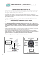
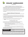
Maintain Proper Clearances Around Heater
•
For maximum efficiency, proper air flow clearances around heater must be maintained.
•
It is important to keep the area immediately adjacent to the heat pump clear of items such as
shrubs and bushes, lawn furniture, chemicals containers, etc. These items can prevent air from
circulating fully through the heater, and will result in inefficient operation or damage to the heat
pump.
•
In addition, do not place objects on top of the heat pump; doing so will lock the air from exiting
the heater, and will result in damage to the compressor and fan motor.
•
Proper clearances are also necessary in order to access the working parts of your heater. A
heater that is easy to "get to," will be a heater that is easy to maintain; service and maintenance
personnel will thank you for keeping the area around your heater unobstructed.
•
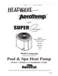
Please see diagrams, below, for specific clearance requirements.
100 & 120 MODELS 12-INCHES
155 MODELS 24-INCHES
(REAR)
OVERHANG
WITH GUTTER
RAIN RUN-OFF
MUST BE
DIRECTED AWAY
FROM UNIT.
5 FT. MINIMUM
CLEARANCE
30” MINIMUM
CLEARANCE
100 & 120 MODELS
1- FT.
155 MODELS 2-FT.
(REAR)
SIDE VIEW (NO SCALE)
20
24INCHES
(SIDE)
24INCHES
(SIDE)
30-INCHES
(FRONT)
TOP VIEW (NO SCALE)
MAINTENANCE & OPERATION
(continued)
Heating Tips
Heating in Cooler Weather...
Late night and early morning, generally being the coolest times of the day, are least efficient for heat
pump operation. For most efficient operation, heat pumps should be timed to operate during the
warmest, daylight portions of the day. Please set water pump controls accordingly.
Pool/Spa Blankets...
A “solar” blanket will significantly reduce your heating bills. Check with the installing dealer to see if
your heat pump was sized to be used in conjunction with a blanket. Blanketed pools will typically lose
only 3 - 4° of heat per night versus 8 - 10° overnight with an un-blanketed pool. Reductions of 40-60%
on heating bills can be achieved by using blankets. (Idea...Contact AquaCal Customer Support (800786-7751) to learn about Liquid Blanket innovations.)
WARNING !
Failure to heed the following may result in permanent
injury or death.
Improperly used, Pool-Spa blankets can become a drowning risk to people and pets.
Blankets are not safety covers. They are not designed to support the weight of a person
or pet. Never enter a pool until the blanket is completely removed (under no
circumstances should anyone swim under the blanket). Follow all safety
recommendations of the blanket manufacturer.
Pool and Spa Combination Heating...
Everything stated for heating a pool applies for heating a spa— only the volume of water being heated
is different. All AquaCal heat pumps come equipped with two thermostats. One thermostat is for the
pool and the other is for the spa. Simply position the pool and spa isolation valves as directed by your
installer; select the appropriate thermostat (pool or spa), whichever you are heating, and with electrical
power and water flow supplied to the heater, the water will be maintained at set point.
Your system can be automated with the addition of an optional AquaCal Universal Heater Controller
(AquaCal part #0097TS). Using this option will save you from having to change the thermostat switch
each time you change from pool to spa and back again. For details, contact your installing dealer or
AquaCal Customer Support (800-786-7751).
Spa Heating & Spa Setback Option...
Air blowing into your spa while it is being heated will very often neutralize or partially counteract the heat
being put into the spa by the heater; this added heat loss equates to increased time to bring your spa to
desired temperature. When heating a spa, be sure to turn off the air blower. Air induced through the
spa jets should also be eliminated, during warm-up, whenever possible.
If your heater is being used to only heat a spa, the POOL thermostat can be used as a setback control:
simply set the pool control at a point 10-15º F below desired spa heat temperature and select the pool
thermostat. This method allows the spa–when not in use–to be held at a heated temperature, but
somewhat lower than normal spa-use temperature. One would want to blanket the spa if using this
setback method. Using spa setback will result in reduced warm up periods over full-cold starts.
21
MAINTENANCE & OPERATION
(continued)
Calculating Initial Heating Time
The time it takes to initially warm your pool or spa depends on several factors.
First, determine how many gallons of water are to be heated. Knowing this, you can then compute the
equivalent pounds of water involved, and the BTU's necessary to heat the volume of water to the
desired temperature.
Next, find the approximate BTU output of your heat pump at the current ambient air temperature (see
specifications table in this manual). Finally, decide upon the temperature at which you plan to maintain
your pool or spa.
The following work sheet can be used to calculate approximately how long it will take your heater to
bring your pool or spa up to temperature. Keep in mind heating times will vary somewhat due to
weather conditions during the period that the heater is in use.
Pool Volume (Length X Width X Average Depth) = _________ Pool Cubic Feet
X Gallons per cubic ft.(7.5) =
X Pounds per Gallon (8.3) =
_________
Pool Gallonage
_________ Pounds of Water
How many degrees do you want to raise the temperature of the pool?
# of Degrees _________ X Pounds of Water (per above) = __________ BTU’s Required
BTU’s Required (per above) ________ I BTU Output of Heater = ______ Hrs. of Operation
Optional Cold Weather Adjustment Factor:
Hrs. of Operation (per above) ______ X 1.25 (60º F outside air (O.A.) Temperature Factor) =
______Hrs. of Operation at 60º F O.A.
At Start Up: Continuous Circulator Pump Operation Required
When starting a heat pump for the first time, it must be permitted to operate, continuously, until the
desired water temperature is attained. This may take several hours, to several days, depending upon
the size of the pool or spa and weather conditions.
If a time clock or similar device controls the operating times of the water circulating pump, temporarily
override the water pump controller, allowing for 24-hour, continuous water pump operation.
Once the body of water has reached the desired temperature, the water pump controller can be reset.
22
MAINTENANCE & OPERATION
(continued)
Seasonal Use & Shut Down
During the Swim Season:
•
During the swim season, even if the pool or spa is not in use, allow water to flow through the
heater. Doing so eliminates the need to reposition valves when you do wish to heat the pool or
spa.
•
During periods when heating or cooling is not desired, leave heater controls in the OFF position.
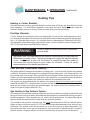
Important !!!
Information Critical to the
Survival of Your Heater
Follows...
Freeze Protection & Extended Shut Down:
In areas where freezing conditions are a rare occurrence, allow the filtration
system to run continuously throughout the freeze period. Typically, during light
freeze conditions, circulating (moving) water will not freeze.
In areas where freezing conditions are prevalent and sustained, the heat pump MUST be winterized; please refer to winterizing instructions, below, and on the following pages.
Winterizing for Hard Freeze Conditions:
CAUTION !
Failure to heed the following can result in damage to
equipment and/or property.
Failure to properly winterize heat pump may result in serious equipment damage. Freeze
damage is not covered under the heat pump warranty.
CAUTION !
Failure to heed the following can result in damage to
equipment and/or property.
While the plumbing connections are in the winterized condition (not fully tightened), it is
imperative pool/spa water not be circulated through the heat pump. Loss of water through
loose plumbing connections may result in damage to circulating pump, pool/spa structure,
and/or other equipment.
(Winterizing continued on page following)
23
MAINTENANCE & OPERATION
(continued)
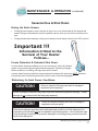
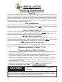
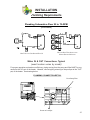
Winterizing Procedure:
1. Disconnect all electrical power to the heater; turn OFF circulating pump.
2. At the two (2) connection unions, disconnect the plumbing to the heater (removal is counterclockwise).
3. Locate the hand drain plug at lower, front corner of heater. See Figure-3 (position may vary
between models). Remove plug.
4. Permit all of the water to drain out of the condenser and then replace the plug; thread the plug in
clockwise until just snug, then apply an additional 1/8 turn.
5. To prevent insects and vermin from entering the plumbing during the winterized period, partially
reconnect the two (2) plumbing connection unions: couple each union one or two threads; this
will permit condensation to drain, but will prevent most insects and animals from entering the
plumbing circuit.
6. Next Season: To ready the heat pump for use, simply retighten plumbing connection unions.
Hand-tight is generally sufficient.
LOCATION
OF
EXTERNAL DRAIN PLUG
-EXACT LOCATION
WILL VARY BY MODEL-
CAUTION !
Failure to heed the following can result in damage to
equipment and/or property.
While the plumbing connections are in the winterized condition (not fully tightened), it is
imperative pool/spa water not be circulated through the heat pump. Loss of water through
loose plumbing connections may result in damage to circulating pump, pool-spa structure,
and/or other equipment.
24
MAINTENANCE & OPERATION
(continued)
Planned Maintenance Program
Just as you would have yearly service performed on your air-conditioning system, regular inspection
and maintenance of your AquaCal heat pump will insure highest operating efficiencies—while also
protecting your investment—potentially extending the useful life of your heat pump far beyond the
warranty period. Our expertly trained factory service technicians offer comprehensive maintenance
procedures designed to insure your heat pump–over the coming years—will continue to operate efficiently
and reliably.
The 20-Point Planned Maintenance Service Includes the Following:
> Check Water Flow
>
Clean Evaporator Coil
>
Check Relay Contacts
>
Check Capacitor Values
>
Check Refrigerant Levels
>
Clean Heat Pump Cabinet
>
Check Fan Blade Clearances
>
Check Flow/Pressure Switch
>
Check Electrical Connections
>
Check Proper Voltage To Unit
>
Oil Fan Motor (As Applicable)
>
Check Fan Motor Amperage Draw
>
Check Pool & Spa Water Chemistry
>
Check and Clean Condensate Drains
>
Check Compressor Amperage Draw
>
Check Water Pump Amperage Draw
>
Acid Wash Source Coil (As Applicable)
>
Check Air Temperature Change Through Evaporator
>
Check Operating Controls and Temperature Sensors
>
Check Water Temperature Change Through Condenser
We recommend all AquaCal heat pump owners take advantage of this annual service starting one year
after the installation of the heater. You will be surprised at the minimal cost of this service– the service
is very reasonably priced for what is included.
For further information, or to schedule Planned Maintenance Service, please contact
AquaCal Customer Support at: 1-800-786-7751.
25
2...
5
e
pag es”
e
d
e
o s or Co
s
l
A Err
“
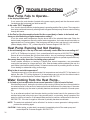
TROUBLESHOOTING
Heat Pump Fails to Operate...
Is the display illuminated?
If not, ensure the main breaker (located at the power supply panel) and the disconnect switch
(located near the heat pump) are both turned ON.
Is the code “FLO” displayed?
If so, check to be sure that the circulating pump is operating and the filter is clean. There may also
be a valve positioned incorrectly allowing water to bypass the heat pump. Be sure water is flowing
through the heater.
Is the Pool or Spa thermostat selected for the correct body of water to be heated, and
have you tried selecting a higher temperature setting?
If not, the actual water temperature may be above that of the selected thermostat. Raise the
desired water temperature above the actual water temperature; the heater should start after an
approximate five (5) minute delay. If the heat pump still fails to start, and the unit is not in defrost
(defrost display code is: “FS”), contact AquaCal Customer Support: 800-786-7751.
Heat Pump Running but Not Heating...
Is the air blowing out of the top of the unit noticeably cooler than the surrounding air?
(A 9°F to 12°F difference is typical.) If not, contact AquaCal for service at: 800-786-7751. But first,
be sure all air coil surfaces are free from obstructions– low roof overhangs, landscaping, walls,
fences, etc., can restrict air flow. The heat pump needs good airflow to operate at peak efficiency.
How many hours/day does the circulating pump operate?
Cooler weather conditions, or heating to a higher than normal temperature, may necessitate
running the heat pump for a longer period of time. Was the heater sized considering the use of a
pool blanket (check with installing dealer)? A blanket can be useful in permitting shorter run times,
in turn leading to substantial energy cost savings.
What is the air outside temperature?
The heat pump may be in the defrost mode if air temperatures are below 50°F. If the heater is in
defrost, the code: ”FS” will be displayed. If air temperatures are not cold, but the defrost code is
still displayed, contact AquaCal Customer Support at: 800-786-7751.
Water Coming from the Heat Pump...
Is it a leak or just condensation from normal operation? Here's how to find out.
Shut the heat pump off, leaving the circulation pump running. Within a few hours, there should be
a marked reduction in the amount of water seen around the bottom of the heat pump. If the water
appears to be drying up, the water is probably harmless condensate, indicative of normal operation.
Or, as an alternate method, test the water draining out the heater base for the presence of the
sanitizer being used in the pool or spa. Using a water test kit, or a test strip, check a sample of the
water for chlorine or bromine. If the sample tests positive for sanitizer, call AquaCal for service at:
800-786-7751. If the test is negative, the water is probably harmless condensate.
NOTE: The water test method will not be effective if an ionizer or ozone generator is being used to
produce the sanitizing agent.
CAUTION! If after testing, a water leak is suspected, immediately shut off the water pump and
contact AquaCal Customer Support: 800-786-7751.
26
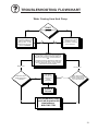
TROUBLESHOOTING FLOWCHART
Heat Pump Fails to Operate
START
START
Y es
No
Is theDisplay Illuminated?,
Is theDisplay Illuminated?,
Display is illuminated. If
Display
is illuminated.
"FLO"
is display
ed, If
"FLO"
is display
ed,
check
to be
sure the
check to be
sure
circulating
pump
is the
circulating
pump
is
operating
and the
f ilter
andmay
the f ilter
isoperating
clean. There
is clean.
also
be a There
v alv e may
also incorrectly
be a v alv e .
positioned
positioned
incorrectly
.
Be
certain water
is
Be certain
water
f lowing
through
the is
f lowing
through the
heater.
heater.
If not, ensure the main
If not,(located
ensure the
main
breaker
at the
power
supply
panel)
breaker
(located
at the
and
the disconnect
power
supply panel)
and (located
the disconnect
switch
near
switch
(located
the
heat pump)
arenear
the heat
pump)
both
turned
ON. are
both turned ON.
Y es
Is the heater
Is the
heater ?
operating
correctly
operating correctly ?
No
Is the Pool or Spa
Is the selected
Pool or Spa
thermostat
f or
thermostat
selected
the
correct body
of f or
the to
correct
body of
water
be heated,
water
and
hav to
e y be
ou heated,
tried
and havaehigher
y ou tried
selecting
selectingsetting?
a higher
temperature
temperaturesetting?
Y es
Is the heater
Is the
heater ?
operating
correctly
operating correctly ?
No
The heater is equipped
The heater
is equipped
with
a f iv e minute
with
a f iv e
delay
. Wait
atminute
least
delay
. Wait
least
f iv e
minutes
to at
allow
f ivtimer
e minutes
to allow
the
to reset.
the timer to reset.
Problem
Problem
Solved.
Solved.
(Verif
y water
(Verif y water
temperature
temperature
settings
are as
settings
desired.)are as
desired.)
Y es
Is the unit operating
Is correctly
the unit operating
?
correctly ?
No
Contact
Contact
AquaCal
AquaCal
for Assistance at
for
Assistance at
800-786-7751
800-786-7751
27
TROUBLESHOOTING FLOWCHART
Heat Pump Running but Not Heating
START
START
Is the air being
discharged
out ofIsthe
the discharged
heater 9-12
thetop
airof
being
out
of the cooler
top of than
the heater
degrees
the 9-12
degrees
cooler
outside
air? than the
outside air?
No
Does the display read : "FS" ?
Does the display read : "FS" ?
Yes
Yes
HEATONLY MODELS: "FS"
HEAT
ONLY
MODELS:
display
ed indicates
air "FS"
displaymay
ed indicates
airto
temperature
be too low
support the
heater's
temperature
may
be too low to
operation.
Heater
will
remain in
support
the
heater's
operation.
will remain in
def
rost untilHeater
air temperature
def rost until
air temperature
rises.
rises.
HEAT-COOLMODELS:"FS"
indicates
heater isMODELS:"FS"
def rosting.
HEAT-COOL
indicates heater is def rosting.
Is the pool pump timer
the
poolextended
pump timer
setIsto
allow
set to of
allow
operation
theextended
heater?
operation of the heater?
HEATONLY MODELS: Has the air
HEAT
ONLY remained
MODELS:abov
Has ethe air
temperature
remained
38ºFtemperature
f or sev eral hours
andabov
"FS"e
has
been
throughout
38ºF
f ordisplay
sev eraledhours
and "FS"
thedisplay
period?
has been
ed throughout
period?Has "FS"
HEAT-COOLthe
MODELS:
HEAT-COOL
MODELS:
"FS"
remained
display
ed longerHas
than
remained(Ifdisplay
ed longer
5-minutes
y es, shut
heaterthan
5-minutesof(Iff .)?
y es, shut heater
of f .)?
Extend the pool pump's
Extend
pool pump's
hours
of the
operation
to
hours
of operation to
accommodate
accommodate
additional
heater run
additional
run
time
required heater
in cooler
time
required in cooler
conditions.
conditions.
Yes
No
HEATONLY MODELS:Ambient
conditions
too MODELS:
cold to operate
HEATONLY
Ambient
conditions
too cold to operate
heater.
HEAT-COOLheater.
MODELS: "FS"
HEAT-COOL
MODELS:
"FS"
display
ed f or 5-minutes
or less
indicates
def rostor less
display
ed normal
f or 5-minutes
operation.
indicates
normal def rost
operation.
No
Yes
No
Is the heater
Is the
heater
perf
orming
perf orming
adequately
?
adequately ?
No
Problem
Problem
Solved.
Solved.
Yes
Call AquaCal
Call AquaCal
for Assistance:
for Assistance:
800-786-7751.
800-786-7751.
28
Problem
Problem
Solved.
Solved.
TROUBLESHOOTING FLOWCHART
Water Coming from Heat Pump
START
START
Has the "Heating"
lamp been
illuminated?
Has the
"Heating" lamp been
illuminated?
Y es
When the heater is operating,
thetoheater
is operating,
it isWhen
normal
produce
up to 8
itgallons
is normal
to produce up to 8
of condensation
gallons
condensation
(water)
per of
hour.
If water
(water)seems
per hour.
If water
drainage
excessiv
e,
drainage
excessiv e,
proceed seems
to TESTING.
proceed to TESTING.
Sanitizer Test
Did the test results
Did the
results
indicate
thetest
presence
indicate
the presence
of sanitizer?
of sanitizer?
No
If heater has not run recently ,
If and
heater
hasis
not
run recently ,
water
coming
and
water heater
is coming
f rom the
heater,
may
f rom
heater may
havthe
e aheater,
water leak.
hav e a water leak.
TESTING:
TESTING:
If using chlorine or bromine
as a pool/spa sanitizer,
If ausing
or bromine
as a pool/spa
sanitizer,
use
test chlorine
strip or test
kit to determine
whether
the
use a
test
to determine
whether the
water
is test
f romstrip
the or
pool
orkit
is normal
condensation.
water is f rom the pool
ORor is normal condensation.
OR
An alternativ e method of determining
a water leak in
Anheater
alternativ
method
of determining
water
leak in
the
is toeturn
the heater
of f f or aaf ew
hours,
the eheater
is to pump
turn the
heater and
of f fsee
or aiff ew
hours,
leav
the water
running,
water
leavcontinues
e the water
and see if water
topump
come running,
f rom the heater.
continues to come f rom the heater.
Turn- Of f Test
No
This would
This
indicate
thewould
water
indicateisthe
water
present
f rom
present
normalis f rom
normal
condensation.
condensation.
No
Does water continue
Does
water
to drain
f rom
thecontinue
heater
tothe
drain
f rom has
the heater
af ter
heater
been
aff ter
has been
of
f orthe
sevheater
eral hours?
of f f or sev eral hours?
Problem
Problem
Solved.
Solved.
Y es
Shut off Water Pump
Shut off Water Pump
and Call AquaCal for
and Call AquaCal for
Assistance:
Assistance:
800-786-7751
800-786-7751
Y es
29
30
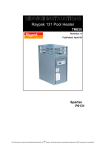
Models
100, 120, & 155
HEATING ONLY
and
HEATING - COOLING
C
I
F
I
C
E
P
S
R
E
N
L
O
A
I
T
A
DE
M
R
O
F
S
IN
W
O
L
L
O
F
Installation
Specifications
&
Controls Configuration
31
DEALER-SPECIFIC TABLE of CONTENTS
GENERAL SAFETY INFORMATION ------------------------------------ 34
DATA PLATE NOMENCLATURE ----------------------------------------- 34
HEATER SPECIFICATIONS -------------------------------------------- 35
Physical Characteristics (dimensional drawings) ----------------- 35
Performance, Size, Weight, Electrical/Water Needs -------------- 36
INSTALLATION INSTRUCTIONS -------------------------------------- 39
Placement of Heater ----------------------------------------------- 39
Indoor Installations --------------------------------------------- 39
Outdoor Installations ------------------------------------------ 39
Required Clearances -------------------------------------------- 39
Irrigation, Rain Runoff, and Landscape Factors ---------------- 40
Equipment Mounting Pad Requirements ----------------------- 40
Anchoring heater to Pad ---------------------------------------- 40
Plumbing Requirements ------------------------------------------- 41
Overview -------------------------------------------------------- 41
Parts and Materials (approved) --------------------------------- 41
In-Line Chlorinators (use and placement of) ------------------ 41
Maintaining Ability to Winterize ------------------------------- 41
Maximum Operating Pressure ---------------------------------- 41
Minium-Maximum Water Flow Rates --------------------------- 41
Plumbing Schematics (layout drawings) ---------------------- 42
32
DEALER-SPECIFIC TABLE of CONTENTS
(CONTINUED)
INSTALLATION INSTRUCTIONS (continued):
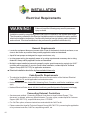
Electrical Requirements ------------------------------------------- 44
General Requirements ------------------------------------------ 44
Code-Specific Requirements ----------------------------------- 44
Connecting External Controllers -------------------------------- 44
Sizing the Electrical Service ------------------------------------ 45
Ground Fault Protection (not recommended) ------------------ 45
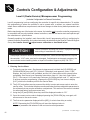
CONTROLS CONFIGURATION & ADJUSTMENTS ---------------------- 46
Level-2 (dealer-service) Programming ---------------------------- 46
1. Entering Service Menu --------------------------------------- 46
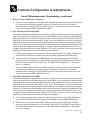
2. Time Delay --------------------------------------------------- 47
3. Configuring for External Controllers ------------------------- 47
4. Water Sensor Calibration ------------------------------------ 47
5. Defrost Sensor Calibration ----------------------------------- 48
6. Spa Dead Band Differential (and adjustment) -------------- 49
7. Pool Dead Band Differential (and adjustment) ------------- 49
8. Changing Service Lock Code & “Back Door” Entry ---------- 50
Level-2 Set Up & Calibration Codes ------------------------------- 51
Factory Default Settings ------------------------------------------- 51
Troubleshooting Using Displayed Codes -------------------------- 52
Mode Jumper and Positioning ------------------------------------- 53
Defrost Systems (described and explained) ---------------------- 55
Water Flow Pressure Switch Adjustment -------------------------- 56
CONTACTING THE FACTORY ------------------------------------------ 58
33
SAFETY INFORMATION
Notice: Heater NOT Repairable by Owner
WARNING !
Failure to heed the following may result in permanent
injury or death.
Heat pumps contain no owner-repairable components. Repairs must not be attempted by
untrained and/or unqualified individuals. If service is deemed necessary, contact installing
dealer or AquaCal Customer Support at (800) 786-7751.
Refrigerant Circuit Service Only by
Qualified, EPA Certified Technician
WARNING !
Failure to heed the following may result in permanent
injury or death.
Heater contains refrigerant under high pressure. Repairs to the refrigerant circuit must not
be attempted by untrained or unqualified individuals. Service must be performed only by
qualified HVAC technicians. Recover refrigerant to relieve pressure before opening system.
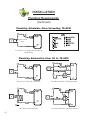
DATA PLATE NOMENCLATURE
1 2 3 4 5 6 7 8 9 10
A T 1 2 0 A R A E W
11
N
12
A
CURRENT RELEASED REVISION
A - INITIAL RELEASE
BRAND
H=
AT=
SB =
TZ =
HeatWave
AeroTemp
SouthBeach
Tropez
OPTIONS
N-NONE
CABINET COLOR
W - CRÈME
B - BLACK
CAPACITY
REFRIGERANT
100 = 90000 Btus/hr
120 = 109000 Btus/hr
155 = 120000 Btus/hr
VOLTAGE
A - 1/60/208-230
B - 3/60/208 - 230
D - 3/50/380
H - 1/50/200-220
RFRG CONTROL
H - HEAT
R - REVERSING
34
E - R22
T - R407C
Z - R410A
CONTROLS
A - ANALOG
D - DIGITAL
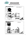
SPECIFICATIONS
Physical Characteristics
100 & 120 MODELS
155 MODELS
35
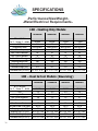
SPECIFICATIONS
-Performance/Size/Weight-Water/Electrical Requirements100 - Heating Only Models
100AHDE
BTU - 80%RH
Air ºF / Water ºF…80/80
90,000
COP
5.8
Voltage/Hz/Phase
208-230/60/1
Min. Circuit Ampacity
38
Max. Fuse or Breaker
60
Rec. Fuse or Breaker
40
Min-Max Water Flow (gpm)
20-70
Shipping weight (lbs)
300
Shipping Size (l x w x h) 40" X 36" X 44"
Uncrated Weight (lbs)
273
Uncrated Size (l x w x h) 34” X 31” X 39”
100BHDE
100DHDT
90,000
73,000
5.8
5.5
208-230/60/3
380-415/50/3
22
10
35
15
25
10
20-70
20-70
300
300
40" X 36" X 44" 40" X 36" X 44"
273
273
34” X 31” X 39” 34” X 31” X 39”
100HHDT
73,000
5.5
200-240/50/1
27
45
30
20-70
300
40" X 36" X 44"
273
34” X 31” X 39”
100 – Heat & Cool Models (Reversing)
100ARDE
BTU - 80%RH
Air ºF / Water ºF…80/80
COP
Voltage/Hz/Phase
Min. Circuit Ampacity
Max. Fuse or Breaker
Rec. Fuse or Breaker
Min-Max Water Flow (gpm)
Shipping weight (lbs)
Shipping Size (l x w x h)
Uncrated Weight (lbs)
Uncrated Size (l x w x h)
36
88,000
5.6
208-230/60/1
38
60
40
20-70
320
40" X 36" X 44"
293
34” X 31” X 39”
100BRDE
100DRDT
100HRDT
88,000
70,000
70,000
5.6
5.4
5.4
208-230/60/3 380-415/50/3
200-240/50/1
22
10
27
35
15
45
25
10
30
20-70
20-70
20-70
320
320
320
40" X 36" X 44" 40" X 36" X 44" 40" X 36" X 44"
293
293
293
34” X 31” X 39” 34” X 31” X 39” 34” X 31” X 39”
SPECIFICATIONS
-Performance/Size/Weight-Water/Electrical Requirements120 - Heating Only Models
120AHDE
BTU - 80%RH
Air ºF / Water ºF…80/80
109,000
COP
5.6
Voltage/Hz/Phase
208-230/60/1
Min. Circuit Ampacity
38 *
Max. Fuse or Breaker
60
Rec. Fuse or Breaker
40
Min-Max Water Flow (gpm)
20-70
Shipping weight (lbs)
323
Shipping Size (l x w x h)
40" X 36" X 44"
Uncrated Weight (lbs)
296
Uncrated Size (l x w x h)
34” X 31” X 39”
120BHDE
120DHDT
120HHDT
109,000
95,000
95,000
5.6
5.5
5.5
208-230/60/3 380-415/50/3
200-240/50/1
27
13
37
45
20
60
30
15
40
20-70
20-70
20-70
323
323
323
40" X 36" X 44" 40" X 36" X 44" 40" X 36" X 44"
296
296
296
34” X 31” X 39” 34” X 31” X 39” 34” X 31” X 39”
120 – Heat & Cool Models (Reversing)
120ARDE
BTU - 80%RH
Air ºF / Water ºF…80/80
103,000
COP
5.4
Voltage/Hz/Phase
208-230/60/1
Min. Circuit Ampacity
38 *
Max. Fuse or Breaker
60
Rec. Fuse or Breaker
40
Min-Max Water Flow (gpm)
20-70
Shipping weight (lbs)
330
Shipping Size (l x w x h)
40" X 36" X 44"
Uncrated Weight (lbs)
303
Uncrated Size (l x w x h)
34” X 31” X 39”
120BRDE
120DRDT
120HRDT
103,000
92,000
92,000
5.6
5.4
5.4
208-230/60/3 380-415/50/3
200-240/50/1
27
13
37
45
20
60
30
15
40
20-70
20-70
20-70
330
330
330
40" X 36" X 44" 40" X 36" X 44" 40" X 36" X 44"
303
303
303
34” X 31” X 39” 34” X 31” X 39” 34” X 31” X 39”
* All A-Voltage 120 heaters with model numbers ending in “B”, MCA = 33
37
SPECIFICATIONS
-Performance/Size/Weight-Water/Electrical Requirements155 - Heating Only Models
155AHDE
BTU - 80%RH
Air ºF / Water ºF…80/80
COP
Voltage/Hz/Phase
Min. Circuit Ampacity
Max. Fuse or Breaker
Rec. Fuse or Breaker
Min-Max Water Flow (gpm)
Shipping weight (lbs)
Shipping Size (l x w x h)
Uncrated Weight (lbs)
Uncrated Size (l x w x h)
127,000
6.3
208-230/60/1
37
60
40
20-70
430
40” x 37” x 47”
403
37” x 33” x 41”
155BHDE
155DHDT
127,000
110,000
6.3
6.3
200-230/60/3
380-415/50/3
30
15.22
50
25
40
20
20-70
20-70
430
430
40” x 37” x 47” 40” x 37” x 47”
403
403
37” x 33” x 41” 37” x 33” x 41”
155GHDE
127,000
6.3
460/60/3
15.22
25
20
20-70
430
40” x 37” x 47”
403
37” x 33” x 41”
155 - Heat & Cool Models (Reversing)
155ARDE
BTU - 80%RH
Air ºF / Water ºF…80/80
COP
Voltage/Hz/Phase
Min. Circuit Ampacity
Max. Fuse or Breaker
Rec. Fuse or Breaker
Min-Max Water Flow (gpm)
Shipping weight (lbs)
Shipping Size (l x w x h)
Uncrated Weight (lbs)
Uncrated Size (l x w x h)
38
120,000
6.1
208-230/60/1
37
60
40
20-70
430
40” x 37” x 47”
403
37” x 33” x 41”
155BRDE
155DRDT
120,000
105,000
6.1
5.9
208-230/60/3
380-415/50/3
30
15.22
50
25
40
20
20-70
20-70
430
430
40” x 37” x 47” 40” x 37” x 47”
403
403
37” x 33” x 41” 37” x 33” x 41”
155GRDE
105,000
5.9
460/60/3
15.22
25
20
20-70
430
40” x 37” x 47”
403
37” x 33” x 41”
INSTALLATION
Placement of Heater
-Indoor InstallationIndoor installations can be problematic, and for that reason are discouraged. However, if no viable
alternative exists, indoor installations may be successfully accomplished provided very exacting criteria
is addressed. Every indoor installation is unique; therefore, there are no specific guidelines for this
type of installation. If considering an indoor installation, you are strongly urged to contact the AquaCal
Engineering department (800-786-7751) for assistance prior to proceeding.
-Outdoor InstallationService and Operational Clearances:
•
To operate correctly, heat pumps require large volumes of air moving over the heat collector.
Allow adequate clearance between the heat pump and walls, fences, shrubs, or other objects.
Refer to required clearance drawings below.
•
Allow five (5) feet of vertical clearance between the top of the heat pump and any roof
overhang or other obstruction. This clearance prevents cold discharge air from recirculating
back into the heat pump (recirculation would reduce the overall performance of the heat pump).
•
The access panel requires removal during installation and service. Do not place plumbing, or
other items, closer than 30” from the front of the heater.
Code Required Clearances:
In addition to the previously stated clearance requirements, follow all applicable local, state, and national
requirements relative to spacing from other objects or equipment.
Required Installation Clearances
100 & 120 MODELS 12-INCHES
155 MODELS 24-INCHES
(REAR)
OVERHANG
WITH GUTTER
RAIN RUN-OFF
MUST BE
DIRECTED AWAY
FROM UNIT.
5 FT. MINIMUM
CLEARANCE
30” MINIMUM
CLEARANCE
24INCHES
(SIDE)
24INCHES
(SIDE)
100 & 120 MODELS
1- FT.
155 MODELS 2-FT.
(REAR)
SIDE VIEW (NO SCALE)
FRONT-REAR-OVERHEAD
30-INCHES
(FRONT)
TOP VIEW (NO SCALE)
FRONT-SIDES-REAR
39
INSTALLATION - PLACEMENT OF HEATER
(continued)
Irrigation, Rainwater Runoff, and Landscape Features
•
Place the heat pump away from direct rain runoff from roofs. If roof slope directs runoff into the
heater, a gutter or rain shield will be required on the roof edge above the heat pump.
•
Relocate or adjust irrigation to avoid water spray directly onto the heat pump.
•
Do not locate the heat pump directly adjacent to plants, shrubs, or bushes. Doing so will prevent
proper air circulation into the unit, and may inhibit access to the heater when service is needed.
•
Consult drawings on previous page (Required Installation Clearances) for proper spacing to
other objects.
Equipment Mounting Pad Requirements
•
The equipment pad shall be constructed of concrete, pressure treated wood, or other material
intended for the use.
•
The equipment pad shall meet all requirements of authorities having code-related jurisdiction.
•
The pad shall be elevated and placed to provide adequate drainage and support to the base of
the heat pump. The pad should be essentially level with just enough pitch to drain condensate
and any other water away from the heater.
•
The pad shall extend–in all directions–(at least) 3" beyond the base of the heat pump.
•
Under no circumstances shall the heater be installed directly onto the earth.
Anchoring Heater to Pad
•
Follow all relevant local, state, or national requirements regarding wind load anchoring.
•
When anchoring is required, use AquaCal optional Hurricane Anchoring Kits.
- AquaCal anchoring kits satisfy, completely, the very stringent Florida Building Code
Section 301.13: Wind Anchoring Requirements.
-Contact AquaCal Parts Group (800-785-7751) to obtain the correct anchoring kit for the
heater being installed.
- Please have the heater model number ready when contacting AquaCal Parts Group.
•
As necessary, contact the AquaCal Technical Support Group (800-786-7751) for assistance in
determining best method of compliance.
WARNING!
Failure to heed the following may result in permanent
injury or death.
Installation made by unqualified persons can result in hazards to the installer and others.
The information contained throughout the “Installation” section is intended for use by qualified
heat pump installation technicians, familiar with the swimming pool/spa service industry
safety standards and methods. Installation to be performed by qualified individuals only.
40
INSTALLATION
Plumbing Requirements
Overview
When planning plumbing system layout, reference the plumbing schematics within this section as a
guide to the sequence of equipment, valves, fittings, etc. The plumbing configurations for typical
installations are diagrammed. In operation, it is imperative the heat pump receive water flow within the
minimum-maximum ranges specified for the particular heat pump. Should the system installation
under consideration not closely match any of the schematics, contact AquaCal Technical Support
Group for advice and guidance: (800) 786-7751.
Parts and Materials
Industry technology changes much too rapidly for AquaCal to specify, with exactness, any items outside
and beyond the heat pump. What is specified is that the heater must be installed in accordance with
all applicable local, state, or national codes & standards.
In-Line Chlorine Feeders
The titanium heat exchanger tube is nearly impervious to damage from acid and chlorine; however,
other pars of the heater may be damaged by concentrated chlorine. Caution: Always place in-line
chlorinators as low, and as far downstream from the heater as possible.
.
Maintain Ability to Winterize
In regions where hard freeze conditions are typical, the unions mentioned below allow for easy
disconnection and re-connection of the heater from/to the plumbing system. Caution: Do not defeat
the function of the unions–use no glue on the threaded portion of the unions.
Water Connections to Heat Pump
All AquaCal heat pumps are supplied with 2" PVC plumbing unions. Connection to site plumbing is
made via PVC solvent cement to the female slip socket of the plumbing unions.
Maximum Operating Pressure: 50-PSI
Minimum - Maximum Water Flow Rates
• All AquaCal 100, 120, and 155 models are designed to operate successfully at flow rates of 20to-70 gallons-per-minute (GPM).
• Design the plumbing system to maintain at least 20-GPM flow through the heater; the heat pump
will not operate correctly, nor reliably, with less than 20-GPM of water flow supplied.
• If water flow rates through the heater will exceed 70-GPM, a spring-check bypass valve will be
required. Please contact AquaCal Engineering Group to obtain the valve specification specific to
your installation (800-786-7751).
• Generally speaking, most residential pools and spas will not require a plumbing bypass unless a
pump of two (2) horsepower, or larger, is used. For bypass valve placement details, see
plumbing schematic contained on next page: “…Flow Greater than 70-GPM.”
CAUTION !
Failure to heed the following may result in damage to
equipment.
Use of an incorrect bypass valve may compromise the heat pump’s efficiency, reliability,
and may void the factory warranty. Please contact AquaCal Engineering Group to obtain
the valve specification specific to your installation (800-786-7751).
41
INSTALLATION
Plumbing Requirements
(continued)
Plumbing Schematic–Flow Exceeding 70-GPM
Bypass Check
Valve
TYPICAL POOL - FLOW GREATER THAN 70-GPM
(2-HP PUMP)
Plumbing Schematics–Flow 20 to 70-GPM
42
TYPICAL POOL - FLOW LESS THAN 70-GPM
POOL/SPILL OVER SPA - TWO PUMP SYSTEM
HEAT PUMP WITH SOLAR PANELS
POOL/SPILL OVER SPA - ONE PUMP SYSTEM
INSTALLATION
Plumbing Requirements
Plumbing Schematics–Flow 20 to 70-GPM
(continued)
HEAT PUMP WITH GAS HEATER BACK UP
MULTIPLE HEAT PUMP INSTALLATION
MINIUM SPACING 24-INCHES
Water IN & OUT Connections- Typical
(exact location varies by model)
For proper operation and maximum efficiency, piping coming from the pump and filter MUST be connected to the "IN" port of the heater. Likewise, connect piping returning to the pool/spa to the "OUT"
port of the heater. See drawing below.
PLUMBING CONNECTION DETAIL
From Pump/Filter
Return to Pool/Spa
43
INSTALLATION
Electrical Requirements
WARNING!
Failure to heed the following may result in permanent
injury or death.
Installation made by unqualified persons can result in hazards to the installer and others.
The information contained in this Electrical Installation section is intended for use by qualified
electrical installation technicians, familiar with electrical service industry safety standards
and methods. Electrical installation to be performed by qualified individuals only.
General Requirements
• Locate the equipment disconnect means within 3-feet of the heater’s electrical enclosure, or as
close to the heater as possible. Always satisfy applicable codes and standards.
• AquaCal heat pumps are designed for copper conductors, only.
• In sizing power wiring, be especially aware of up-sizing requirements necessary due to wiring
distances. Always satisfy applicable codes and standards.
• Multiple heaters installed at same site generally require special sequencing controls (an “ASC”
controller will be required). If yours is a multi-heater installation, contact AquaCal Technical
Support Group (800-786-7751) for application assistance.
• Electrical installation should be by licensed electrician only.
Code-Specific Requirements
• The electrical installation must conform to the most current version of the National Electrical
Code, NFPA No.70, and all applicable local and state codes.
• National Electrical Code, Article 680; Swimming Pools, Fountains, and Similar Installations, shall
apply.
• National Electrical Code, Article 440, Air-Conditioning and Refrigeration Equipment, shall apply.
Connecting External Controllers
• See document entitled: “Connecting External Controllers to AquaCal Heat Pumps”; This
document is shipped with every AquaCal heater. For extra copies, contact AquaCal Customer
Support (800-786-7751); request literature piece: “LTP0050.”
• For Call-Flex option, reference instructions received with the Call-Flex kit.
• Please contact the AquaCal Technical Support Group (800-786-7751) concerning the application
of any external controller, Call-Flex, sequencing control, etc.
44
INSTALLATION
Electrical Requirements (continued):
Sizing the Electrical Service...
Reference the Equipment Data Plate
• AquaCal 100, 120, and 155 model heat pumps have two (2) identical data plates affixed: one can
be found outside the unit, on right front corner; the second data plate is located behind the front
access panel, on the electrical enclosure cover.
• Refer to either equipment data plate for unit-specific electrical power supply requirements.
• Based on data plate information, size wiring, wiring devices, and over-current protection per
applicable codes and standards.
• Refer to drawing below for data plate items specific to electrical installation requirements. On the
installed heater data plate, the areas depicted below, numbered 1-8, will contain the information
required to size the electrical service and over-current protection.
ELECTRICAL PORTION of DATA PLATE
A Word Concerning Ground-Fault Protection
• The National Electrical Code (NEC) contains no standards requiring Ground-Fault Interruption
protection (via GFI Circuit Breaker or otherwise) of “Fixed” or “Stationary” equipment, under
article 680: Swimming Pools, Fountain, & Similar Installations, or Article 440: Air-Conditioning &
Refrigeration Equipment.
• The preceding standards govern the installation of AquaCal (and other manufacturers’) heat
pumps. AquaCal heat pumps are designed, and safety tested by a certified laboratory, to be
installed under applicable standards detailed within the NEC.
• AquaCal does not recommend the use of ground fault protective devices in conjunction with heat
pumps. Service calls, found to be due to “nuisance” tripping of ground fault devices, are
not covered under the AquaCal factory warranty.
45
Controls Configuration & Adjustments
Level-2 (Dealer-Service) Microprocessor Programming
(Includes Configuration for External Controllers)
Level-2 programming involves configuring the controller for specific site characteristics. To explain,
this programming is where the controller is set to operate with, or without, an external controller;
where sensor calibrations are performed; and where changes to other factory default parameters are
made.
Before transferring use of the heater to the owner, the installer must insure the controller programming
is compatible with any site-installed external controllers, and that the heater starts and operates per
the manufacturer’s specifications.
Generally speaking, the installer’s main focus within Level-2 programming will be in configuring for
external controller compatibility. And, unless instructed to do otherwise by the AquaCal Technical Support
Group, the installer should not adjust sensor calibration or dead-band values.
CAUTION !
Failure to heed the following may result in equipment damage
and voiding of manufacturer’s warranty.
Heat pumps contain no owner-serviceable components. Owner-initiated adjustments, beyond
the controller “LOC” code, must not be attempted. If adjustments are deemed necessary, the
owner should contact installing dealer or AquaCal Customer Support at (800) 786-7751.
1. Entering Service Menu:
A. To enter the service menu, Simultaneously depress and hold both the [UP ARROW] and
[DOWN ARROW] keys until [CF1] (Celsius / Fahrenheit) code appears. (Note: if “000”
displays, the User Lock Code is enabled, and the ULC pass code must be entered before
proceeding. See Owner-Level Operating Instructions, page-14: “User Lock Code Option
[ULC].” If the owner’s ULC pass code is unknown, the factory default code “17” may be used
to access controller programming.) Depress the [POOL/SPA] key four times to display
[LOC], which is the entrance point for the Service Menu.
B. The [LOC] code allows service personnel the ability to enter and access code to enter the
service menu. This includes the above-mentioned codes that have adjustable parameters in
the software that may require calibration or adjustment. This section of the menu is intended
for authorized factory service personnel only.
C. Using the [UP] and [DOWN] arrow keys scroll the displayed number to “50.”
D. Once the correct service code is displayed pressing the [POOL/SPA] key, one again, will
allow access to the service menu.
E. The first service parameter displayed will be [dEL] (4 -minute time delay on make).
NOTE: Depressing the [POOL/SPA] key will save the displayed value in
any menu parameter and advance to the next service menu parameter.
(Continued
46
on Next Page)
Controls Configuration & Adjustments...
Level-2 Microprocessor Programming...continued:
2. Time Delay [dEL]:
A. With the [dEL] (4 minute time delay) code message displayed use the [UP] or [DOWN]
arrow key to select either “1” to allow the time delay to remain active or “0” to deactivate the
time delay. Not pressing depressing any buttons for 15 seconds will allow the controller to
save the selection and return to the normal operating mode. Pressing the {POOL/SPA] key
will also save the selection and step to the next menu parameter [JAO] (External Controller
Interface).
B. CAUTION!!!: The time delay should only be deactivated for service convenience and must
be reactivated prior to placing the heat pump back is service. Failure to reset the time delay
feature could result in permanent damage to the heat pump compressor.
3. Configuring for External Controllers [JAO] or [FS2]:
A. Configuring for External Controllers Using [JAO] Selection :
1) Follow the steps 1a. through 1d. above to enter the service menu. Once [dEL] is
displayed, press the [POOL/SPA] key until the display shows [JAO].
2) With the [JAO] (External Controller Interface) code message displayed, use the [UP] or
[DOWN] arrow keys to select either “0” to disable the External Controller Interface, “2” to
connect a thermostat type controller (2-wire connection), or “3,” to connect a thermostat
selector type controller (3-wire connection).
B. Configuring Remote Flow Switch / Automatic Thermostat Switching Using [FS2] Selection:
1) Follow the steps 1a. through 1d. above to enter the service menu. Once [dEL] is
displayed, press the [POOL/SPA] key until the display shows [FS2].
2) With the [FS2] (Remote Flow Switch / Automatic Thermostat Switching) code message
displayed, use the [UP] or [DOWN] arrows to select either “0” to disable Remote Flow
Switch / Automatic Thermostat Switching, “1” to enable Remote Flow Switch / Automatic
Thermostat Switching.
NOTE: ALL FLOW SWITCH KITS PRODUCED BY AQUACAL ARE SHIPPED WITH FULL INSTALLATION AND
PROGRAMMING INSTRUCTIONS. PLEASE CONTACT AQUACAL CUSTOMER SUPPORT (800-7867751) IF ADDITIONAL COPIES OF THESE INSTRUCTIONS ARE NEEDED.
4. Water Sensor Calibration [tSC]:
If it is believed the displayed pool or spa water temperature does not match the actual
temperature, follow the steps below to verify and adjust the controller as necessary. Be certain
to use an accurate thermometer:
A. With the circulating pump in operation, and water moving through the heater, use a reliable
thermometer to measure the temperature of the pool or spa water. Be sure to measure the
water temperature away from returns. The object is to accurately determine the temperature
of the water entering the heater.
B. Once you have measure the water temperature, compare the result to the heater’s
displayed water temperature. If the water temperatures are the same or within 1oF, no
calibration is necessary. If the temperatures differ by 2 to 3oF, calibration is necessary…
Perform calibration procedure as follows:
(Continued on Next Page)
47
Controls Configuration & Adjustments...
Level-2 Microprocessor Programming...continued:
4. Water Sensor Calibration...continued:
C. Follow the steps 1a. through 1d. above to enter the service menu. Once [dEL] is displayed,
press the [POOL/SPA] key until the display shows [tSC] (Water Temperature Calibration).
Using either the [UP] or [DOWN] arrow keys, calibrate the water temperature sensor by
increasing or decreasing the numeric value displayed to match the water temperature
reading measured on your thermometer. The controller can be adjusted to +10oF to –10oF
from the nominal displayed temperature. However, offset calibrations greater than 3oF
should be avoided… Such large offsets generally indicated problems with the method of
water temperature measurement, a water sensor not properly inserted into the well, or other
equipment issues. Do NOT attempt to mask such issues through offset calibration.
D. Once the corrected temperature is displayed, Not pressing depressing any buttons for 15
seconds will allow the controller to save the selection and return to the normal operating
mode. Pressing the {POOL/SPA] key will also save the selection and step to the next menu
parameter [dSC], (Defrost Sensor Calibration).
5. Defrost Sensor Calibration [dSC]:
In the event the defrost Sensor requires calibration, the following steps must be followed closely
to ensure optimal defrost control.
A. Turn the heater off at the main circuit panel.
B. Remove the unit’s front panel to gain access to the defrost sensor. The defrost sensor will
be found strapped to the suction line in combination with the TXV bulb on heat only models,
or on the evaporator’s suction heater independent from the TXV bulb for heat and cool
models.
C. Carefully remove the insulation from around the sensor area.
D. Using a highly accurate, surface-mount thermometer, attach the thermometer probe to the
suction line immediately adjacent to the Defrost Sensor. After the thermometer probe is
securely attached to the suction line, reinstall the insulation foam around the sensor.
E. With the foam insulation and the front reinstalled, restart the unit, allowing it to run for 10minutes… The suction line temperature should have stabilized at this point… Note the
suction line temperature as measured by the thermometer probe.
F. Follow previous steps “1a.” through “1d.,” to enter the service menu. Once [dEL] is
displayed, press the [POOL/SPA] key until the display shows [dSC] (Defrost Sensor
Calibration). With the service menu parameter [dSC] displayed pressing either the [UP] or
[DOWN] arrow key once will display the current temperature value of the defrost sensor.
G. Compare the controller’s displayed defrost sensor temperature with the reading on the
thermometer. If the temperatures are the same or within 1oF, no calibration is necessary. If
the temperatures differ by 2 to 3oF, calibration is necessary. The controller can be adjusted
to +10oF to –10oF from the nominal displayed temperature. However, offset calibrations
greater than 3oF should be avoided… Such large offsets generally indicated problems with
the method of suction line temperature measurement, a defrost sensor not properly
attached to the suction line, or other equipment issues. Do NOT attempt to mask such
issues through offset calibration.
(Continued
48
on Next Page)
Controls Configuration & Adjustments...
Level-2 Microprocessor Programming...continued:
5. Defrost Sensor Calibration...continued:
H. Once the correct temperature value has been selected not pressing depressing any buttons
for 15 seconds will allow the controller to save the selection and return to the normal
operating mode. Pressing the [POOL/SPA] key will also save the selection and step to the
next menu parameter [dBS], (Dead Band for Spa).
6. Spa Dead Band Differential [dBS]:
The dead band differential determines the number of degrees that the water temperature must fall
below the set point before the thermostat closes (Heat Mode). In the cooling mode the dead band
differential determines the number of degrees that the water temperature must rise above the set
point before the thermostat closes again. When in the auto-changeover mode the dead band
differential operates in the same manner as described above for heating mode and cooling modes.
However, in all modes the thermostat will open when the set point is reached independently of the
direction the water temperature is changing. The factory spa dead band differential is set to 1oF. It
is highly recommended that the factory default of 1oF remain, however, if form some reason the
dead band requires adjustment, follow the steps outlined below:
A. Follow the steps 1a. through 1d. above to enter the service menu. Once [dEL] is displayed,
press the [POOL/SPA] key until the display shows [dBS] (Spa Dead Band Differential).
B. With the service menu parameter [dBS] displayed, pressing either the [UP] or [DOWN]
arrow keys once will display the current setting. Using the [UP] or [DOWN] arrows keys will
increase or decrease the value respectively. The differential is adjustable in 1o increments
from 1 to 5-degrees.
C. Once the desired dead band value has been selected not pressing depressing any buttons
for 15 seconds will allow the controller to save the selection and return to the normal
operating mode. Pressing the {POOL/SPA] key will also save the selection and step to the
next menu parameter [dBP], (Dead Band Pool).
7. Pool Dead Band Differential [dBP]:
The dead band differential determines the number of degrees that the water temperature must fall
below the set point before the thermostat closes (Heat Mode). In the cooling mode the dead band
differential determines the number of degrees that the water temperature must rise above the set
point before the thermostat closes again. When in the auto-changeover mode the dead band
differential operates in the same manner as described above for heating mode and cooling modes.
However, in all modes the thermostat will open when the set point is reached independently of the
direction the water temperature is changing. The factory pool dead band differential is set to 1oF. It
is highly recommended that the factory default of 1oF remain, however, if form some reason the
dead band requires adjustment, follow the steps outlined below:
A. Follow the steps 1a. through 1d. above to enter the service menu. Once [dEL] is displayed,
press the [POOL/SPA] key until the display shows [dBP] (Pool Dead Band Differential).
B. With the service menu parameter [dBP] displayed, pressing either the [UP] or [DOWN]
arrow keys once will display the current setting. Using the [UP] or [DOWN] arrows keys will
increase or decrease the value respectively. The differential is adjustable in 1o increments
from 1 to 5 degrees.
(Continued
on Next Page)
49
Controls Configuration & Adjustments...
Level-2 Microprocessor Programming...continued:
7. Pool Dead Band Differential...continued:
C. Once the desired dead band value has been selected, not pressing depressing any buttons
for 15-seconds will allow the controller to save the selection and return to the normal
operating mode. Pressing the {POOL/SPA] key will also save the selection and step to the
next menu parameter [LOC], (LOCK CODE).
8. Changing the Service Lock Code and “Back Door” Entry:
A. Changing the Code…
The factory default Service Lock Code is “50”. Service personnel are strongly advised to
retain the factory default setting. However, should unauthorized access to Level-2 (Service)
menu be suspected, it may be necessary to select a code other than “50”. To change the
Service Lock Code:
1) Follow the steps 1a. through 1d. above to enter the service menu. Once [dEL] is
displayed, press the [POOL/SPA] key until the display shows [LOC] (LOCK CODE).
2) Press the [UP] arrow key to display the current service lock code value. With the current
value displayed the [UP] arrow key will increase the value while the [DOWN] arrow key
will decrease the value. When the desired value is displayed not pressing depressing
any buttons for 15 seconds will allow the controller to save the selection and return to the
normal operating mode. Pressing the {POOL/SPA] key will also save the selection and
step to the next menu parameter. It is recommended, however, unless attempting to
prevent tampering, that the factory setting of: “50” remain in use.
B. Back-door Access (For use when correct Service Lock Code is unknown):
1) Simultaneously depress and hold the [POOL/SPA] and [UP ARROW] keys until the
display shows “888”. This operation will reset the controller to the factory default
settings.
2) The factory reset will change the service lock code back to the factory setting “50”. In
addition, all other settings (including external controller configuration) are returned to the
factory defaults. See section in this manual entitled: “Factory Default Settings” for a
complete list of factory default parameters.
(End...Level-2 Microprocessor Programming)
50
Controls Configuration & Adjustments...
Microprocessor Level-2 Set Up & Calibration Codes
Service Adjustable Parameters
Code
Description
Factory Setting
Range
[LOC]
Service Lock Code
50
00-99
[dEL]
4-minute Delay on Make
1
0/1
[JAO]
External Controller Interface
0
0/2/3
[FS2]
Flow Switch/Auto T-Stat Switching
0
0/1
o
o
o
o
[tSC]
Water Sensor Calibration
Factory Calibrated
+10 to –10 of display
[dSC]
Defrost Sensor Calibration
Factory Calibrated
+10 to –10 of display
[dBS]
Spa Dead Band Differential
1
o
1 to 5
[dBP]
Pool Dead Band Differential
1
o
1 to 5
o
o
o
o
Microprocessor Factory Default Settings
Level –1 and Level-2 Default Settings
Menu
Code
Description
Default Value
Range
Level-1
[CF1]
Celsius/Fahrenheit
1
0/1
Level-1
[ULC]
User Lock Code
0
0/1
Level-1
[ELC]
Enter Lock Code
0
00-99
Level-1
[CFO]
Call / Flex
0
0/1/2
Level-1
[LOC]
Service Lock Code
50
00-99
Mode
Key Pad
Operating Mode
OFF
For Heat Only
OFF/HEAT
For Heat & Cool
OFF, HEA,
COO, ACH
Thermostat
Key Pad
Thermostat Settings Pool & Spa
OFF
45 F – 104 F
Level-2
[dEL]
4-minute Delay on Make
1
Level-2
[JAO]
External Controller Interface
0
Level-2
[FS2]
Flow Switch / Auto T-Stat
Switching
0
o
o
0/1
0/2/3
0/1
o
o
o
o
Level-2
[tSC]
Water Sensor Calibration
Factory
Calibrated
+10 to –10 of
displayed value
Level-2
[dSC]
Defrost Sensor Calibration
Factory
Calibrated
+10 to –10 of
displayed value
Level-2
[dBS]
Spa Dead Band Differential
1
o
1 to 5
Level-2
[dBS]
Spa Dead Band Differential
1
o
1 to 5
o
o
o
o
51
Controls Configuration & Adjustments...
Troubleshooting Using Displayed Codes
Interpreting Error Codes
The HP7R heat pump microprocessor controller is designed to be self-diagnostic through the display
of various fault codes.
Owners & Operators: If you believe you are experiencing a problem with the heater, and feel a need to
call the factory for assistance, it will be beneficial to let the factory Service Representative know which
code is being displayed. Having this information at hand will permit the Service Representative to work
through–with you–any site related issues causing or contributing to the problem. Then, if after working
through site-related issues the heater is still not functioning correctly, the Service Representative will
offer to set up a service visit. As necessary, please Contact AquaCal Customer Support Group (800786-7751).
Dealers and Service Centers: For troubleshooting use, listed below are all possible fault messages
output by the microprocessor, what the codes mean, and possible causes with solutions for the
indicated problem. Please contact AquaCal Technical Support Group, as necessary (800-786-7751).
WARNING !
Failure to heed the following may result in permanent
injury or death.
Heat pumps contain no owner or operator repairable components. Repairs must not be
attempted by untrained and/or unqualified individuals. If service is deemed necessary, contact
installing dealer or AquaCal Customer Support at (800) 786-7751.
52
Message
Error Description
Possible cause
[dPO]
Defrost Sensor Open
Cut or loose sensor wiring
[PO]
Water Temperature
Sensor Open
Cut or loose sensor wiring
[dPC]
Defrost Sensor Shorted
Short circuit in defrost sensor wiring or defective sensor.
[PC]
Water Temperature
Sensor Shorted
Short circuit in water temperature sensor or defective sensor.
[LP]
Refrigerant System Low
Pressure Switch Open
System refrigerant charge low, defective low pressure switch, clogged
evaporator coil, or defective wiring.
[HP]
Refrigerant System High
Pressure Switch Open
Low water flow, defective high pressure switch, or defective wiring.
[HP5]
5 High Pressure Faults
Within One Hour (Unit
Locked)
See causes for [HP]
[LP5]
5 Low Pressure Faults
Within One Hour (Unit
Locked)
See causes for [LP]
[OTA]
Over Temperature Alarm<
o
Temperature over 110 F
(Unit Locked)
Defective compressor contactor, defective controller, or defective water
temperature sensor
[FLO]
Low or No Water Flow
Detected
Circulating pump off or filter dirty, isolation valves set improperly,
defective or improperly set heater water pressure switch
[FS]
Heater in Defrost Mode
Normal function in lower air temperatures. Fan continues to run and
compressor is off. Compressor will restart when air-coil temperature
o
reaches 38 F or above.
[CSE]
Control System Error
Controller may need to be reset. Disconnect then reconnect power to
controller. If error continues replace control board, display board, or both.
Controls Configuration & Adjustments...
Microprocessor Mode Jumper Positioning
Mode Jumper Explained
The HP7R microprocessor is designed to operate as a Heat-Only or a Heating & Cooling controller.
The selection between the two choices is made through the positioning of a mode jumper contained
on the microprocessor board. The position of the jumper is set at the factory, and is dependant
upon the design of the heater being controlled. Heaters designed to heat only have the
microprocessor mode jumper set in the heat-only mode; heaters capable of both heating and
cooling (reversing) have their microprocessor mode jumpers set to permit control of both heating
and cooling.
Important: The position of the mode jumper must match the capabilities of the heat pump. Simply
placing the mode jumper to the heating and cooling position, with a heater designed to heat only, will
not make a heat-only heater heat & cool. In fact, a mis-positioned mode jumper will cause heater
control difficulties.
Verifying the Mode Jumper Position is Correct
1. Apply electrical power to the heater.
2. Review the available modes by repeatedly pressing the [MODE] key
A. Heat-Only Models: The [MODE] key functions should appear as: [OFF] and [HEA].
B. Heat-Cool Models (Icebreakers): The [MODE] key functions should appear as: [OFF], [HEA],
[COO], and [AHC].
3. If the above modes do not display correctly for the heater being serviced, the selector jumper,
located on the microprocessor PC board, is likely placed in the wrong position. To correct this
condition, the jumper connections will need to be repositioned. See repositioning instructions,
below.
Repositioning the Mode Jumper
Use this procedure if it is determined the mode jumper positioning is incorrect. The mode jumper is
located on the microprocessor controller board, within the heater’s electrical enclosure.
WARNING !
Failure to heed the following may result in permanent
injury or death.
This is NOT an owner or operator procedure. Repairs must not be attempted by untrained
and/or unqualified individuals. Risk of Electrical Shock…Ensure all electrical power to the
heater has been disconnected prior to removing the heater front access panel. Leave electrical
power disconnected throughout the following jumper repositioning procedure.
1. To access the jumper, first remove the heater front entry panel; then, remove the metal cover
from heater electrical enclosure. For layout details of the microprocessor control board, see
figures on next page.
2. Locate the mode jumper in the upper right hand corner of the control board. If the jumper is
found to be incorrectly positioned, gently disengage the jumper by pulling it directly away from
the control board.
3. Per the figures on the following page, identify the correct location for the jumper, and gently
reposition the jumper leaving one pin uncovered. Note: The jumper should cover two (2) pins:
one always being the middle pin, and the other the correct pin for the features of the heat pump.
53
Controls Configuration & Adjustments...
Microprocessor Mode Jumper Positioning...continued:
54
Controls Configuration & Adjustments...
Defrost Systems- Described
DEFROST CYCLE (HEAT ONLY UNITS):
The microprocessor controller monitors the heater’s air-coil temperature, minimizing air-coil freezeup during cooler weather conditions. If the controller senses air-coil temperatures conductive to
making ice, the heater’s compressor operation is interrupted while the fan is allowed to continue in
operation.
With the compressor off, the air-coil begins to warm to the surrounding air temperature. When aircoil temperatures rise above approximately 38oF, the compressor is restarted and heating resumes.
In the event air temperatures remain below approximately 38oF, the compressor will remain off until
the air temperature rises above 38oF. The unit will not heat the pool water as long as the compressor
remains off.
During defrost cycles, when the controller has stopped compressor operation, the display will read:
[FS].
DEFROST CYCLE (HEAT & COOL UNITS):
The microprocessor controller, in conjunction with the defrost sensor, constantly monitors the
heater’s evaporator (air-coil) temperature. Should the controller sense ice or frost has formed on
the evaporator, sufficient in amount as to affect the heater’s performance, an active defrost cycle
(more below) is initiated. Before initiating a defrost command, the controller defrost logic looks at
both the air-coil temperature, and the length of time the coil has remained at an ice-making
temperature.
Active defrost involves using hot refrigerant gas, from the compressor, to rapidly remove ice or frost
from the evaporator coil. In practice, during a hot gas defrost cycle, valving, internal within the
refrigerant system, reverses the flow of the refrigerant; this reversal of flow temporarily makes the
air-coil the condenser. During hot gas defrost, the air-coil warms very quickly, and accumulated ice
and frost is rapidly melted. Under most conditions, the evaporator will be completely cleared in
under 5-minutes.
HEAT & COOL DEFROST SEQUENCE DETAILS:
• When the controller senses air-coil temperatures conductive to making ice, the unit will enter a
50-minute defrost delay (counting) period.
•
During the counting period, the fan and compressor will continue to operate, and the water will
continue to be heated. During the counting period, it is normal to see a moderate amount of frost
and ice formation on the air coil.
•
If, after the 50-minute counting period, the controller senses a need to defrost:
1. The refrigerant circuit reversing valve will be activated, changing the flow of hot refrigerant
gas from the pool water heat exchanger to the air-coil.
2. Fan operation will be suspended, permitting maximum heating of the air-coil.
3. The reverse cycle will continue until either:
A. The air-coil attains a predetermined temperature (indicative of total defrost), or;
B. Until 5-minutes has elapsed (regardless of total defrost having occurred).
•
During hot gas defrost cycles, the compressor will not deactivate; rather, the compressor will
continue operation throughout the sequence. Upon completion of the defrost cycle (as
terminated per “A” or “B,” above), the reversing valve will be deactivated, fan operation will
recommence, and water heating will resume.
55
Controls Configuration & Adjustments...
Water Flow (Pressure) Switch Adjustment
Occasionally, plumbing system design features will create a situation whereas the heater will abnormally
cycle on the water flow circuit. This situation will be evident if the circulator pump is operating, the filter
is clean, and all water valves are set to flow water through the heater– but the error code: “FLO”
remains displayed (or displays intermittently). In these rare instances where the factory water pressure
switch (WPS) setting will not satisfy site conditions, a WPS adjustment, to enable normal heater
operation, is possible.
WARNING !
Failure to heed the following may result in permanent injury
or death.
WPS adjustment procedure to be performed by experienced service personnel only; procedure is
NOT a homeowner-based task, and must not be attempted by individuals lacking adequate electrical
and mechanical experience. BEWARE: ROTATING FAN PROP HAZARD: fan may start during
water switch adjustment. Keep hands clear of fan blade at all times.
Locate Water Pressure Switch and Identify Type:
1. Before proceeding with switch adjustment, be absolutely certain the heater is receiving correct
water flow. Leave circulation pump operating during water pressure switch (WPS) adjustment
process.
2. Remove heater front cover and locate the water pressure switch. The switch will be found
attached outside of the electrical enclosure, at lower edge; exact location will vary by heater
model (see photo P-1, on following page).
3. AquaCal heat pumps may come equipped with either of two (2) water pressure switches: “Len
Gordon” or “TecMark” brand (see photos P-2 and P-3, on following page, to determine which
brand pressure switch is installed). The adjustment procedures differ slightly between the two
brands.
To Adjust a “Len Gordon” Switch:
1. Locate the black, rectangular plastic tab, located on the forward-facing side of the switch
(reference P-2 on page following). The black rectangle is a wheel lock tab; slide the tab fully
LEFT to unlock the adjustment wheel.
2. With water pump operating, and electrical power supplied to the heater, slowly rotate the top of
the adjustment wheel TOWARDS you until the FLO code (just) disappears. WARNING: watch
for rotating fan blade; depending upon the state of the control circuit time delay, the heater may
start simultaneous with the WPS adjustment.
3. Once the adjustment has been completed, slide the wheel locking tab fully back to the righthand, locked position.
To Adjust a “TecMark” Switch:
1. (Reference photo P-3 on page following.) TecMark switches do not have an adjustment wheel
lock.
2. With water pump operating, and electrical power supplied to the heater, slowly rotate the top of
the adjustment wheel AWAY from you until the until the FLO code (just) disappears. WARNING:
watch for rotating fan blade; depending upon the state of the control circuit time delay, the heater
may start simultaneous with the WPS adjustment.
56
Controls Configuration & Adjustments...
Water Flow (Pressure) Switch Adjustment...continued:
To Complete the Adjustment Procedure– Either Brand Switch:
1. With electrical power remaining ON to the heater and heater operating, shut off the power to the
circulating pump. If the switch has been correctly adjusted, when the water pump stops, the
heater will shut off and the “FLO” code will display.
CAUTION: If the heater continues to operate with water pump off, readjust water pressure switch
to ensure heater will not run without water flow.
2. Reinstall heater front cover.
P-2, Len Gordon Style Switch
P-1, WPS Location
P-3, TecMark Style Switch
SHOULD ADJUSTMENT OF THE WATER PRESSURE SWITCH PROVE UNSUCCESSFUL, CONTACT
AQUACAL TECHNICAL SUPPORT (800-786-7751); SITE-SPECIFIC FACTORS MAY REQUIRE
THE INSTALLATION OF AN EXTERNAL FLOW SWITCH.
57
CONTACTING THE FACTORY
What We Need to Know When You Call Us
If you should need to call AquaCal for service or parts, please have the following information ready:
Model: ________________________________
Serial Number: __________________________
Installation Date: ________________________
Having the above information ready will speed up the service process and
allow us to respond more quickly. A brief but concise description of what the
unit is, or is not doing, will also help us to help you.
Please call up toll-free at: (800) 786-7751. We are here to serve you from
8 a.m. to 5 p.m. EST, Monday through Friday. If calling after hours, our voice
mail system will handle your call. Be sure to leave your name, complete address, and telephone number.
If you prefer, you may FAX the information to: (727) 821-7471.
(Be certain to provide your full address and a daytime telephone number.)
Thank You !
58
NOTES
___________________________________________________________________________________
__________________________________________________________________________________
___________________________________________________________________________________
_________________________________________________________________________________
_________________________________________________________________________________
_________________________________________________________________________________
___________________________________________________________________________________
__________________________________________________________________________________
___________________________________________________________________________________
_________________________________________________________________________________
__________________________________________________________________________________
________________________________________________________________________________________
___________________________________________________________________________________
____________________________________________________________________________________
_________________________________________________________________________________
__________________________________________________________________________________
_________________________________________________________________________________
__________________________________________________________________________________
59
2737 24th St. North
St. Petersburg, FL 33713
1-800-786-7751
60