1
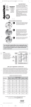
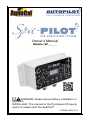
Owner’s Manual
Models: SP_-_ _ _
WARNING: Read manual before installation or
operation.
INSTALLER: This manual is the Purchaser’s Property
and is to remain with the SpaPilot®.
LTP0091 REV V1.0
RECORD YOUR SPAPILOT ® INFORMATION
Control Unit model
Control Unit serial number
Model = SP_-O__ or
Model = SPW (all)
Model = SP_-I__
Cell type = Over the Wall (Convection)
Cell type = Inline
Cell serial number
Installer
Install Date
CONTACT INFORMATION
Web
Phone
Customer Service Hours
Address
www.AutoPilot.com
(727) 823-5642
8 a.m. to 5 p.m. EST, Monday – Friday
AquaCal AutoPilot, Inc.
2737 24th Street North
St. Petersburg, Florida 33713
USA
If you should need to call AquaCal AutoPilot, Inc. for questions, service or
parts, please have your model and serial numbers available. Please also have
the name of your installer and date of your equipment’s installation. If you have
questions, please refer to our website for the latest manual revisions,
additional information and helpful service advice.
SYMBOL KEY
CAUTION
WARNING
READ MANUAL BEFORE INSTALLATION & OPERATION
WASTE ELECTRICAL & ELECTRONIC EQUIPMENT DIRECTIVE
i
TABLE OF CONTENTS
RECORD YOUR SPAPILOT® INFORMATION ............................................... I
CONTACT INFORMATION............................................................................ I
SYMBOL KEY ............................................................................................... I
IMPORTANT SAFETY INSTRUCTIONS ...................................................... IV
®
HOW THE SPAPILOT WORKS ................................................................... 1
DISPLAY, LED INDICATORS, BUTTONS .................................................... 1
SPA WATER PREPARATION ...................................................................... 2
Add Water .......................................................................................... 2
Add Salt ............................................................................................. 2
Establish Sanitizer Residual ................................................................ 3
Recommended Water Parameters....................................................... 3
DECIDE WHICH MODE TO USE: PERCENTAGE OR USAGE...................... 4
PERCENTAGE MODE – MENU TREE.......................................................... 5
PERCENTAGE MODE – SETTING THE OUTPUT % .................................... 6
Percentage Setting - Set a % Output for the Spa Size .......................... 6
Percentage Setting – Add to % to Increase Output for Regular Usage .. 6
Percentage Mode Example: ................................................................ 7
PERCENTAGE MODE.................................................................................. 8
Boost – How and When to Use............................................................ 8
The “Day” Feature .............................................................................. 9
The “Reversing” Feature ................................................................... 10
The “Configuration” Feature .............................................................. 11
The “Spa Size” Feature ..................................................................... 12
The “Information” Feature ................................................................. 13
USAGE MODE – MENU TREE ................................................................... 14
USAGE MODE – SETTING THE OUTPUT .................................................. 15
Set Sanitizer Output Based on Spa Size ............................................ 15
Set Sanitizer Output Based on Spa Usage......................................... 16
Usage Mode Example....................................................................... 16
USAGE MODE ........................................................................................... 17
Boost – How and When to Use.......................................................... 17
The “Day” Feature ............................................................................ 18
The “Reversing” Feature ................................................................... 20
The “Configuration” Feature .............................................................. 21
The “Spa Size” Feature ..................................................................... 22
The “Information” Feature ................................................................. 23
WINTERIZING THE SPAPILOT® ................................................................ 24
CLEANING THE OVER THE WALL (CONVECTION) CELL ........................ 25
CLEANING THE INLINE CELL ................................................................... 26
ii
WHAT IS INCLUDED WITH THE SPAPILOT® ............................................ 27
INSTALLATION – SURFACE MOUNT CONTROL UNIT ............................. 28
OEM – INSTALLATION – FLUSH MOUNT CONTROL UNIT....................... 29
OEM – INSTALLATION CONT. – POWER, INLINE CELL........................... 30
OEM – INSTALLATION CONT. – POWER, INLINE CELL........................... 31
INSTALLATION - WIRELESS REMOTE CONTROL ................................... 32
TROUBLESHOOTING ................................................................................ 33
SPECIFICATIONS ...................................................................................... 37
Model Breakdown – AC Power, Cell Type, etc. .................................. 37
Control Unit Specifications ................................................................ 37
Bezel Cutout Diagram ....................................................................... 38
Bezel Diagram .................................................................................. 38
Control Unit Diagram ........................................................................ 38
Cell Specifications ............................................................................ 39
Chlorine Output - lbs/day (g/day) ....................................................... 39
Inline Cell Diagram ........................................................................... 40
Over the Wall (Convection) Cell Diagram ........................................... 40
AGENCY CERTIFICATIONS ...................................................................... 41
NOTES: ..................................................................................................... 42
iii
IMPORTANT SAFETY INSTRUCTIONS
WARNING: READ MANUAL BEFORE
INSTALLATION AND OPERATION: This manual contains
important information on the installation, use, and safety recommendations for
®.
®
the SpaPilot It is your responsibility to install and use the SpaPilot safely.
WARNING: Failure to heed the following may result in injury or death:
•
•
•
•
•
•
•
•
Disconnect all AC power when installing or servicing this system. If the
supply cord is damaged, it must be replaced immediately by the
manufacturer or a qualified service representative. Follow all state,
local, and National Electrical Code(s) (provincial and Canadian
Electrical Code(s) if applicable).
®
The SpaPilot must be connected only to a supply circuit that is
protected by a ground-fault circuit-interrupter (GFCI). Contact a qualified
electrician if you cannot verify that the circuit is protected by a GFCI.
The GFCI must be tested on a routine basis. To test, push the GFCI test
button. Power should be interrupted. Push the reset button. Power
should be restored. If the GFCI fails to operate in this manner, it is
defective. If the ground-fault circuit-interrupter (GFCI) interrupts power
to the equipment without the test button being pushed, a ground current
is flowing and there is a possibility of an electrical shock. Do not use
equipment. Disconnect the equipment and have the problem corrected
by a qualified service representative before using.
SpaPilot® models that use an AC/DC adaptor require the AC/DC
adaptor be installed on a GFCI protected outlet with an approved
weather protective shielded enclosure that covers the adaptor.
Do not open the SpaPilot® control unit or power adapter. There are no
owner/user-serviceable components inside. Repairs must not be
attempted by untrained and/or unqualified individuals. If service is
deemed necessary, contact the installing dealer or AquaCal AutoPilot
Customer Support.
Do not immerse. The SpaPilot® control unit is not intended for
submersion, but may be installed in the spa zone. The SpaPilot® control
unit must be located or fixed so that it cannot fall into the spa.
Suitably rated CERTIFIED/APPROVED power supply cord, plug and
strain relief or cable gland appropriate for the applicable country are
intended to be installed and replaced by a manufacturer’s authorized
agent or qualified personnel.
Removable, Over the Wall type, cell should be lifted out of the spa and
stored out of the way when the spa is occupied. Do not drop, throw, or
otherwise mishandle the cell. Place the cell back in spa when
unoccupied. (This warning does not apply to the “Inline” cell.)
Children must be closely supervised at all times around the spa and spa
equipment. Children should be supervised so that they do not play with
the SpaPilot® Unit, Bromine/Chlorine Cell, or the wireless remote.
iv
IMPORTANT SAFETY INSTRUCTIONS
•
•
•
•
•
•
•
This unit (including the wireless remote) is not to be operated by
®
children. Likewise, the SpaPilot remote should be mounted or stored
so that it is not accessible by the same.
®
The SpaPilot unit (including the wireless remote) is intended to be
installed, operated and maintained by qualified/trained personnel
without reduced physical, sensory and mental capabilities.
The proper residual of chlorine or bromine and water parameters must
be maintained. Improper water parameters can present a serious health
hazard. See the section, Recommended Water Parameters, on page 3.
This is not an automatic water care system. The spa owner/user is
ultimately responsible for maintaining proper sanitary water conditions.
The user must regularly test the spa water to ensure that adequate
levels of bromine or chlorine are generated to achieve proper sanitizer
levels.
Heavy spa usage and higher water temperatures may require a higher
®
SpaPilot output or manual shocking in order to maintain proper free
available chlorine / bromine residuals.
Supplemental sanitation may be needed under some conditions such
as:
o The “Inline” cell unit is required to operate only when the filtration
pump is running. SpaPilot® sanitizer output may be reduced when
the filtration pump operation is reduced.
o The “Over the Wall” cell will not generate sanitizer when it is
removed during spa usage.
For proper sanitation, spas must be completely drained periodically.
o Replacement Interval (days) = (Spa Gallons ÷ 3) ÷ Average Users
per day
For example: 300 gallon spa used by 2 adults 2 times a day 2
times a week =(300 ÷ 3)÷
o
(
Or Replacement Interval (days) = (Spa Liters ÷ 11.35) ÷ Average
Users per day
For example: 1000 liter spa used by 2 adults 1 time a day 5
times a week = (1000÷11.35)÷
•
•
= 62 days
Refill spa with water and prepare the spa water for use again. See
the section, Spa Water Preparation, on page 2.
Users should always shower before entering the spa.
Filter cartridges should be cleaned or replaced at regular intervals;
otherwise part of the sanitizer created by the SpaPilot® will only serve to
oxidize the accumulated dirt trapped in the filter.
Check the expiration dates of test strips/kits. Test results may be
inaccurate after expiration dates.
To avoid damaging splashes, always add acid to water, never water to
acid. Wear safety glasses and use other appropriate personal protection
equipment.
v
o
•
•
)= 88 days
IMPORTANT SAFETY INSTRUCTIONS
•
•
•
Always follow the instructions on the manufacturer's label whenever
handling or using chemicals.
Leave spa cover open for at least 30 seconds prior to use to allow the
escape of trapped gases.
®
The SpaPilot cell may be cleaned manually by the owner if needed.
Hazardous fumes/liquids could be present during this process. Remove
power from unit before cleaning. Determine your cell type and then refer
to the appropriate procedure, Cleaning the Over the Wall (Convection) Cell
procedure on page 25, Cleaning the Inline Cell, on page 26.
CAUTION: Failure to heed the following may result in equipment
damage not covered under warranty:
• The SpaPilot® must be installed and operated as specified in this
manual.
• Maintain water parameters as listed in this manual. Cell life may be
shortened due to excessive scale (calcium) formation in the cell if pH,
Total Alkalinity, and Calcium Hardness guidelines are not followed.
• Never use sharp or metallic objects to remove calcium build-up.
Scraping or scratching the titanium blades will damage the cell’s
catalyst coating, causing premature failure of the SpaPilot® cell. Follow
the directions in this manual for properly cleaning the SpaPilot® cell.
• Operating the SpaPilot® at reduced salt levels or with low water
temperatures will shorten the life of the cell.
• Water must be drained from the SpaPilot® cell when winterizing the spa.
• Do not operate the wireless remote while in the spa. The wireless
remote is not waterproof. Do not submerge the remote. The SpaPilot®
wireless remote should be located and/or used in a manner so that it
cannot fall into the spa.
• Only sodium bromide and sodium chloride salt products approved for
use in pools/spas should be used. Do not allow granular salt to pile up
in one location as staining of the spa may occur. Circulate water until
the salt is dissolved.
• Maintaining excessively high bromine, chlorine, sodium chloride, or
sodium bromide levels above the recommended range may contribute
to the corrosion or damage of the spa or the spa components.
• SpaPilot® operation with UV or ozone units is not recommended.
• The SpaPilot® is intended for use on covered spas, not swimming pools.
• The SpaPilot® is intended to operate at an altitude of less than 6500 ft
(2000 m) above sea level.
PRODUCT DISPOSAL: The SpaPilot® unit must be disposed separately in
accordance with the local waste disposal legislation in force.
SAVE THESE INSTRUCTIONS
vi
HOW THE SPAPILOT® WORKS
•
•
•
•
Salt is dissolved in the water. Sodium Chloride is used for Chlorine
Production. Sodium Bromide is used for Bromine Production. The salt
concentration level is normally maintained below the taste threshold.
®
The SpaPilot automatically converts the salt into a sanitizer.
The sanitizer reverts back to salt after treating the water. The salt is not
consumed.
Salt is only lost when spa water is replaced, overflows, splashes out or
leaks. A small amount may also be lost on bathers or their apparel.
DISPLAY, LED INDICATORS, BUTTONS
System Status LED
○ No color – Power Off
• Green – OK, Power On
• Red (Flashing) - Warning
Primary Display
• Output
• Settings
• & more
Control
Unit Front
Panel
Salt Level LEDs
• Red – Check (High)
•
•
•
•
•
•
Programming
buttons (4 + 4)
• DOWN
• UP
• SELECT
• BOOST
Amber – Warning
Green
Green – In Range
Green – In Range
Amber – Warning
Red
BOOST LED
• Blue = Boost on
Wireless
Remote
1
– In Range
– Check (Low)
SPA WATER PREPARATION
ADD WATER
1)
2)
Fill the spa with clean water and heat it to at least 80°F (27°C).
®
Test the water using an AquaChek Spa 6-in-1 test strip. Check for pH,
Total Alkalinity and Calcium Hardness. Obtain the following water
parameters using additives recommended by your spa manufacturer.
PARAMETER
pH
Total Alkalinity
Calcium
Hardness
TARGET
7.5
90
MIN
7.2
80
MAX
7.8
100
UNITS
pH
ppm (mg/l)
200
150
250
ppm (mg/l)
ADD SALT
1)
For chlorine generation (Chlorinator) add pool salt (sodium chloride).
For bromine generation (Brominator) add either 99% pure sodium
bromide or a combination of sodium chloride and 99% pure sodium
®
bromide. [The SpaPilot system will create a bromine residual
(Brominator) when the combination mixture is used. Sodium chloride is
much less expensive than sodium bromide. Using option 2 below (a
mixture of sodium chloride and sodium bromide) will still provide all of
the benefits of a Brominator but at a lower cost for salt.]
SALT ADDITION TABLE
DESIRED
SANITIZER
ADD PER 100
GALLONS
SALT
ADD PER 500
LITERS
Chlorine
Sodium Chloride
1 lb.
(1 ½ cups)
550 g
(2 cups)
Bromine
(option 1)
Sodium Bromide
1 lb.
(1 ¼ cups)
550 g
(1 ¾ cups)
Sodium Chloride
16 oz.
(1 ½ cups)
550 g
(2 cups)
Sodium Bromide
2 oz.
(1/8 cup)
50 g
(1/8 cup)
Bromine
(option 2)
2)
3)
Confirm the water circulation pump remains on until the salt has fully
dissolved.
If after adding salt you see a red salt LED on your SpaPilot®, test the
level of salt (sodium chloride) in the spa; use an AquaChek® Salt test
strip. To test the level of sodium bromide; use an AquaChek® Sodium
Bromide Test strip (not included).
•
If salt level is low, then add additional salt.
•
If salt level is high, then partially drain the spa and refill to dilute
salt.
•
Always fill spa completely before measuring salt level. (Evaporation
will increase salt concentration; dilution will reduce.)
PARAMETER
Salt
TARGET
1300
MIN
MAX
UNITS
1000
3000
ppm (mg/l)
2
SPA WATER PREPARATION
ESTABLISH SANITIZER RESIDUAL
1)
2)
Add a shock sanitizer approved by your spa manufacturer to prepare
the spa for quick use. CAUTION: Do not use hydrogen peroxide.
Or if time permits, let the SpaPilot® generate the sanitizer residual.
a) Press the “BOOST” button. Set the boost time for 2-3 hours per 100
gallons (4-5 hours per 500 liters). Additional boost time may be
required if combined chlorine levels are high.
®
b) Test the water when Boost is complete, using an AquaChek Spa
6-in-1 test strip. Confirm water parameters are met for free chlorine
or bromine. Repeat Boost for additional hours if needed.
PARAMETER
Free Chlorine
Bromine
TARGET
4
5
MIN
3
4
MAX
5
6
UNITS
ppm (mg/l)
ppm (mg/l)
RECOMMENDED WATER PARAMETERS
Maintain water parameters as shown below. High pH can reduce the
effectiveness of sanitizers. High Calcium Hardness can result in scaling on spa
or cell. Excessively high Chlorine/Bromine sanitizer or salt levels can potentially
damage spa equipment. Check your spa manual for acceptable additives to
raise or lower pool water parameters to recommended levels. See the table on
the previous page for adding salt.
PARAMETER
Free Chlorine
Bromine
pH
Total Alkalinity
Calcium Hardness
Salt
TARGET
4
5
7.5
90
200
1300
MIN
3
4
7.2
80
150
1000
MAX
5
6
7.8
100
200
3000
UNITS
ppm (mg/l)
ppm (mg/l)
pH
ppm (mg/l)
ppm (mg/l)
ppm (mg/l)
The following test strips are recommended for measuring the water parameters:
• AquaChek® Spa 6-in-1 test strips (for measuring Total Chlorine, Total
Bromine, Free Chlorine, Total Alkalinity, pH and Calcium Hardness)
• AquaChek® Pool & Spa Salt test strips (for
measuring sodium chloride)
• The AquaChek® Pool & Spa Sodium
Bromide test strips (for measuring sodium
bromide) (not included)
3
DECIDE WHICH MODE TO USE: PERCENTAGE OR
USAGE
®
Your SpaPilot operates in one of two modes, “Percentage” or “Usage”. The
®
SpaPilot is shipped from the factory in the “Percentage” mode.
• The “Percentage” mode is the simpler of the two. The output can be
adjusted up or down from 0 to 100% to set the desired sanitizer output
level. The sanitizer is dispensed evenly over time at the set percentage.
• The “Usage” mode is still simple but has a few more features. Sanitizer
demand is entered by adjusting two different settings independently: Size
and Usage.
o The Size of the spa is entered. This setting is used to
determine the minimum amount of sanitizer generated to
maintain sanitizer levels when the spa is not in use.
o The Usage is entered. This setting is used to determine the
additional amount of sanitizer based on the actual bather
usage of the spa.
If the SpaPilot® detects that there have been no key presses for 30 days,
the usage will automatically drop to 0. Only the chlorine generation based
on the Size of the spa will remain active. This can assist in protecting your
spa from excessive sanitizer levels during periods of non-use.
Your spa may have a “summer” mode that reduces circulation pump time
to minimize pump kinetic energy from overheating the spa. Selecting the
SpaPilot® “Day” (operating hours) setting to match the circulation pump
run time will result in the SpaPilot® automatically generating the sanitizer
faster. This is needed to compensate for the reduced daily operating
hours.
• The “Boost” feature works the same for both “Percentage” and “Usage”
modes. Press the “BOOST” button and the sanitizer output can be set to
100% for the next 1 to 24 hours.
Select the mode that works best for you, “Percentage” or “Usage”, and then
proceed to the appropriate section that follows. Remember, you can change
modes again later if desired.
4
PERCENTAGE MODE – MENU TREE
Day (1 to 24 hours)1
(day =24 hr)
Percentage pct
output displayed
(0 to 100%)
(100)
Reversing
(2, 4, or 8 hours)
(rev = 4 hr)
If Boost bst is
active the blue LED
will be on
Configuration (Mode)
(Percentage or Usage)
(
= pct)
• (0-24 hours) =24
• Boost countdown will
be displayed
• (23.9 to 0.1 hours)
Spa Size in gallons1
(0 to 1200)
(spa = 1 200)
23.9 to =0.1
Information
(Volts, Amps, Life
Remaining, Program,
Year, Day, Serial)
(Inf)
On the Normal
Displays:
• Press BOOST to toggle
off/on
• Press UP/DOWN to
change parameter value
• Press SELECT for 5
seconds to go to
secondary menu
End – Exit Menu
(end)
On the Secondary Menu Displays:
• Current parameter value will be displayed
• Press SELECT to change parameter
o Then current parameter value will flash
o Press UP/DOWN to scroll thru values
o Press SELECT to save new value and return to
Secondary Menu display
• Press UP/DOWN to skip parameters
1
1
Not active in Percentage Mode
5
PERCENTAGE MODE – SETTING THE OUTPUT %
The following pages outline operation in “Percentage” mode (factory default).
®
To change your SpaPilot from “Usage” mode to “Percentage” mode, refer to
the section, The “Configuration” Feature, on page 11.
If the SpaPilot® is now in “Usage” mode and you want to keep it that way, refer
to the section, USAGE MODE – Menu Tree, on page 14.
WARNING: It is the user’s responsibility to regularly maintain and adjust
the sanitation output settings as required.
The amount of sanitizer required will vary depending on various factors
including spa size, water temperature, spa cover usage, exposure to direct
sunlight, filtration pump runtime, blower activation times, and bather load. The
output range is from 0% (Off) to 100% (Continuous On).
For simplicity, the sanitizer demand is separated into 3 factors:
1) Output percentage (%) required when the spa is idle – primarily based
on size and other non-use factors
2) Output percentage (%) required for regular bather usage
3) Spikes in usage – which will be handled by BOOST (1-24 hours)
PERCENTAGE SETTING - SET A % OUTPUT FOR THE SPA
SIZE
Press the “UP” or “DOWN” button to adjust the SpaPilot® output. As a
starting point, you can set the output percentage to approximately 2%
per 100 gallons (400 liters) of water. Additional adjustments may be
needed for the other non-usage factors.
2) Wait 24 hours, then test the water using an AquaChek® 6-in-1 test strip.
•
If free chlorine level is above 5 ppm (mg/l) (or bromine is above 6
ppm (mg/l)), decrease the percentage level.
•
If free chlorine level is below 3 ppm (mg/l) (or bromine is below 4 ppm
(mg/l), increase the percentage level.
1)
PERCENTAGE SETTING – ADD TO % TO INCREASE
OUTPUT FOR REGULAR USAGE
1)
Press the “UP” or “DOWN” button to add output percentage as needed
for each bather who regularly uses the spa.
2) As a starting point, add an additional 10% per bather per day, per ½
hour of usage, to the output percentage used for the spa size. This will
need to be adjusted up or down for your particular application.
3) After using the spa, test the water.
•
If free chlorine level is above 5 ppm (mg/l) (or bromine is above 6 ppm
(mg/l)), decrease the percentage level.
•
If free chlorine level is below 3 ppm (mg/l) (or bromine is below 4 ppm
(mg/l)), increase the percentage level.
6
PERCENTAGE MODE
PERCENTAGE MODE EXAMPLE:
Amelia has a 400 gallon (1500 liters) spa. Based on the size, Amelia had set
the minimum output to 8% for her spa. Two people will be using it for ½ hour
each on a regular basis. She added a 20% output for two bathers. Total = 28%
After using the spa, Amelia tested the water and noticed the sanitizer level was
low. She adjusted the percentage up another 5% for two bathers. After using
the spa and re-testing, she found the percentage output was ideal.
SPA
Spa Output
Percent
+
Usage Output
Percent
=
Total
Percentage
Original %
8
+
2 Bathers (20%)
=
28
Bather
Adjustment
8
+
2 Bathers (25%)
=
33
7
PERCENTAGE MODE
BOOST – HOW AND WHEN TO USE
®
The “Boost” feature is normally used to temporarily increase the SpaPilot
sanitizer production to the maximum possible for the selected time period to
handle unusual spikes in sanitizer demand, such as might be expected by:
• Spa usage above the daily norm.
• After a water change.
• The owner does not want to adjust the “Percentage” setting to
correspond to varying daily usage. (Note: The output percentage setting
must be manually changed to reduce sanitizer generation but BOOST
will automatically turn off after the selected run time.)
As a starting point: After a water change, set the boost time for 2-3 hours per
100 gallons (400 liters). Additional boost time may be required if the combined
chlorine level in the source water is high.
Another reference starting point: The boost time can be set to 2 hours per ½
hour of bather use. This will need to be adjusted up or down based on
individual spa conditions.
1)
2)
Press the “BOOST” button. The blue LED above the “BOOST” button will
turn on. The previously selected boost cycle time will be displayed.
(bst will flash then = 1 or the last selected time value will display
steady. The default boost time is 1 hour; range is 0 to 24 hours.)
If desired, use the “UP” or “DOWN” button to adjust the number of hours
the SpaPilot® will operate in boost mode. The boost cycle will
automatically turn off when the boost time expires. The most recent boost
cycle time will be recalled the next time “BOOST” is pressed.
For example: If set to 1 hour, display will show =
1 then after 6
0.9, then ……. 0.1. Boost expires after 1 hour; the
display reverts to usage setting u=0.
minutes
3)
After the boost cycle is complete, test the water using an AquaChek® Spa
6-in-1 test strip.
• If free chlorine level is above 5 ppm (mg/l) (or bromine is above 6 ppm
(mg/l)), boost hours were set too high.
o Confirm boost is off (Blue LED will be off).
o The next time the boost feature is used, it will need to be set to a
shorter number of hours.
• If free chlorine level is below 3 ppm (mg/l) (or bromine is below 4 ppm
(mg/l)), boost hours were set too low.
o Press “BOOST” button and add additional boost hours to raise
sanitizer level.
o Test periodically with an AquaChek® Spa 6-in-1 test strip.
8
PERCENTAGE MODE
THE “DAY” FEATURE
day (Displays day then =24 then
hr)
The “Day” setting is not used when in the “Percentage” mode. To use this
feature, change to the “Usage” mode.
®
If your SpaPilot has an “Inline” cell, not an “Over the Wall” cell, then the
following applies:
•
When required, some spa controllers allow the owner to shorten the
spa circulation pump operation to reduce the spa heat gain
(overheating) associated with kinetic energy imparted by the
circulation pump.
•
If the circulation time of the spa is reduced, then the output of the
chlorine generator with an “Inline” cell is reduced proportionally. The
®
SpaPilot maximum sanitizer output capacity will decrease when the
circulation pump run time is reduced. See the table entry, Chlorine
Output - lbs/day (g/day), in the section, Cell Specifications, on page 39 to
determine the SpaPilot® chlorine output if the Spa circulation pump
does not run continuously.
WARNING: A SpaPilot® with an “Inline” cell must be electrically interlocked
with the spa circulation pump to prevent sanitizer generation when there is no
circulation.
WARNING: The sanitizer output capacity of a SpaPilot® with an “Inline” cell
will be reduced if the spa circulation pump hours of operation are reduced.
Supplemental sanitation may be required.
9
PERCENTAGE MODE
THE “REVERSING” FEATURE
REV (Displays rev then =
4 then hr)
®
The SpaPilot has an automatic cleaning feature to prevent calcium buildup
between the cell blades. The cell polarity is reversed every 4 hours (factory
default).
CAUTION: The reverse setting is optimized for cell life and normally should
not be changed.
The reversing feature is very effective on the “Inline” cell. Reversing is less
effective on the “Over the Wall (Convection)” cell due to the lower water flow
through the cell. Periodic manual cleaning of the “Over the Wall” cell may be
required. Locating the cell in the path of the circulation return jet will minimize
manual cleaning cycles.
1)
Press and hold the “SELECT” button for five seconds until day
appears on the display.
2)
day then =24 then hr displays repeatedly.
•
•
(24 hours is the normal default setting.)
Press the “DOWN” button once and the reversing menu is displayed.
3)
•
rev then = 4 then hr displays repeatedly.
•
(4 hours is the default)
Press the “SELECT” button once to change hours.
4)
5)
6)
•
= 4 The “ 4” value will flash.
Press “UP” or “DOWN” button to adjust reversal intervals. Intervals are
2, 4, or 8 hours.
Press the “SELECT” button once to lock in the interval. The new value
will display.
Press the “DOWN” button until End appears. Press the “SELECT”
button to exit secondary menu. (Or wait 15 seconds to automatically
exit.)
10
PERCENTAGE MODE
THE “CONFIGURATION” FEATURE
(Displays
then =
then PCT)
This feature allows you to select one of two SpaPilot® operational modes:
“Percentage - pct” or “Usage - UsE”. The factory default is “Percentage”
mode. Before changing the “Configuration” mode, review the section, Decide
which mode to use: Percentage or usage, on page 4.
Press and hold “SELECT” button for five seconds until day appears on the
display.
1)
•
day then =24 then hr displays repeatedly.
•
(24 hours is the normal default setting.)
Press the “DOWN” button twice to skip parameters until the
configuration selection is displayed.
•
If in Usage mode the display will show repeatedly:
•
2)
then =
then UsE
If in Percentage mode the display will show repeatedly:
then =
then pct
Press “SELECT” button once to change mode.
•
•
=
=
then UsE will flash repeatedly or
then pct will flash repeatedly.
3)
4)
Press the “UP” or “DOWN” button to select UsE or pct.
Press the “SELECT” button once to lock in the new selection. The new
value will display.
5)
Press the “DOWN” button until End appears. Press the “SELECT”
button to exit secondary menu. (Or wait 15 seconds to automatically
exit.)
11
PERCENTAGE MODE
THE “SPA SIZE” FEATURE
s=1
The Size of the spa is not used in the “Percentage” mode. The size setting is
used to determine the minimum amount of sanitizer generated to maintain
sanitizer when in the “Usage” mode. To use this feature, change to the
“Usage” mode.
Although not used in the “Percentage” mode, the Spa Size can be changed by
entering the secondary menus. Size can only be entered in gallons.
DISPLAY
s=1
s=2
s=3
s=4
s=5
s=6
s=7
s=8
s=9
s10
s11
s12
SPA SIZE
GALLONS
LITERS
100
380
200
760
300
1140
400
1510
500
1890
600
2270
700
2650
800
3030
900
3410
1000
3790
1100
4160
1200
4540
12
PERCENTAGE MODE
THE “INFORMATION” FEATURE
Inf
®
This feature allows you to view SpaPilot operational status and information.
This is helpful when troubleshooting.
1)
Press and hold “SELECT” button for five seconds until day appears
on the display.
day then =24 then hr displays repeatedly.
(24 hours is the normal default setting.)
2)
3)
Press the “DOWN” button to skip parameters until INF is displayed.
Press the “SELECT” button once to display information diagnostics.
Each reading will be displayed twice. (Press the “UP” arrow to back up
or the “DOWN” arrow to advance to the next reading.) After all values
are shown, the display will automatically return to INF.
4)
Press the “DOWN” button until End appears then press the
“SELECT” button to exit secondary menu. (Or wait 15 seconds to
automatically exit.)
DESCRIPTION
DISPLAY
SYMBOL
VALUE
EXAMPLE
Voltage
v=
9.81
Amperage
A=
1.61
Cell Life
Remaining
Lr=
Software Program
Version
Service
Parameter
Service
Parameter
Year of
manufacture
99
C1.0
EXAMPLE EXPLANATION
In this example the cell
voltage is “9.81”
In this example the cell
amperage is”1.61”
In this example the cell
has a remaining life of
99%
In this example the
software version is “C1.0”)
Used by customer service
for troubleshooting
Used by customer service
for troubleshooting
In this example the year of
manufacture is “2013”
th=
99
tS=
99
Yr=
13
Day of
manufacture
dAY
340
In this example the day of
manufacture is “340”
Unit Number
N=
999
In this example the unit
number is “999”
13
USAGE MODE – MENU TREE
Day (1 to 24 hours)
(day =24 hr)
Usage USE output
displayed
(0 to 10)
(u=3)
Reversing
(2, 4, or 8 hours)
(rev = 4 hr)
If Boost bst is
active the blue LED
will be on
Configuration (Mode)
(Percentage or Usage)
(
= UsE)
• (0-24 hours) =24
• Boost countdown will
be displayed
• (23.9 to 0.1 hours)
23.9 to =0.1
Spa Size in gallons
(0 to 1200)
(spa = 1 200)
On Normal Displays:
Information
(Volts, Amps, Life
Remaining, Program,
Year, Day, Number)
(Inf)
• Press BOOST to toggle
off/on
• Press UP/DOWN to
change parameter value
• Press SELECT for 5
seconds to go to
secondary menu
• Press SELECT for 1
second for shortcut to
change the Spa Size in
gallons setting (s=3)
End – Exit Menu
(end)
On the Secondary Menu Displays:
• Current parameter value will be displayed
• Press SELECT to change parameter
o Then current parameter value will flash
o Press UP/DOWN to scroll thru values
o Press SELECT to save new value and return to
Secondary Menu display
• Press UP/DOWN to skip parameters
14
USAGE MODE – SETTING THE OUTPUT
The following pages outline operation in “Usage” mode. To change your
®
SpaPilot from “Percentage” mode to “Usage” mode, refer to the section, The
“Configuration” Feature, on page 21.
®
If your SpaPilot is configured to “Percentage” mode and you want to keep it
that way, refer to the section, PERCENTAGE MODE – MENU TREE, which starts
on page 5 for operating instructions.
WARNING: It is the user’s responsibility to regularly maintain and adjust
the sanitation output settings as required.
The amount of sanitizer required will vary depending on various factors
including spa size, water temperature, cover usage, exposure to direct
sunlight, filtration pump runtime, blower activation times, and bather load.
For simplicity, the sanitizer demand is separated into 3 factors:
1) Sanitizer required when the spa is idle – primarily based on size and
other non-use factors (Size = 0 to 1200 gallons)
2) Sanitizer required for regular bather usage (Usage = 1 to 10)
3) Spikes in usage – which will be handled by BOOST (1 to 24 hours)
SET SANITIZER OUTPUT BASED ON SPA SIZE
1)
2)
Look up the spa water capacity in your spa owner’s manual.
Press the “SELECT” button. Current spa size value will be displayed.
3)
(S=1 - default size is 100 gallons)
Press the “UP” or “DOWN” button to scroll through sizes: 0 to 1200
4)
5)
gallons. ( S=1 to S12)
Press the “SELECT” button to lock in the size closest to your spa size.
Wait 24 hours then test the water using an AquaChek® 6- in-1 test strip.
•
If free chlorine level is above 5 ppm (mg/l) (or bromine is above 6
ppm (mg/l)), decrease the size level.
•
If free chlorine level is below 3 ppm (mg/l) (or bromine is below 4
ppm (mg/l)), increase the size level.
VALUE
DESCRIPTION
S=1
Value is approximately 100
gallons
DISPLAY SEQUENCE:
Spa, =
s12
Value is approximately 1200
gallons
Spa, = 1, 200
15
, 100
USAGE MODE
SET SANITIZER OUTPUT BASED ON SPA USAGE
1)
2)
3)
Press the “UP” or “DOWN” button to set the usage level. The output
range is from 0 (Off) to 10. (u=0 - default usage is 0)
As a starting point, we suggest you can set the usage level to 1 per user
per half hour of use. This will need to be adjusted up or down for your
particular application.
After using the spa, test the water.
•
If free chlorine level is above 5 ppm (mg/l) (or bromine is above 6
ppm (mg/l)), decrease the usage level.
•
If free chlorine level is below 3 ppm (mg/l) (or bromine is below 4
ppm (mg/l)), increase the usage level.
USAGE MODE EXAMPLE
Leo has a 400 gallon (1500 liter) spa. Leo and his wife will be using it for a half
hour on a regular daily basis. He has already set his minimum output to 4 (Spa
Size S=4) He sets the usage level to 2 (U=2). After using the spa, he
noticed the sanitizer level was low. He increased the usage level by 1 (U=3).
After using the spa and re-testing, he found the usage level was ideal.
VALUE
USAGE LEVEL
Original Bather Level
2 Bathers = 2
u=2
Bather Adjustment
2 Bathers = 3
u=3
AUTOMATIC SANITIZER USAGE OUTPUT CUTOFF DUE TO
INACTIVITY
If the SpaPilot® detects that there have been no button presses for 30 days,
the Usage will automatically drop to 0 (u=0 after 30 days of inactivity). Only
sanitizer generation based on the Size of the spa will remain active. This
feature can assist in protecting your spa from excessive sanitizer levels during
periods of non-use.
16
USAGE MODE
BOOST – HOW AND WHEN TO USE
The boost feature is normally used to temporarily increase the SpaPilot®
sanitizer production to the maximum possible for the selected time period to
handle unusual spikes in sanitizer demand, such as might be expected by:
• Spa usage above the daily norm.
• After a water change.
• The owner does not want to adjust the “Usage” setting to correspond to
varying daily usage. (Note: The usage setting must be manually
changed to reduce sanitizer generation but BOOST will automatically
turn off after the selected run time.)
As a starting point: After a water change, set the boost time for 2-3 hours per
100 gallons (400 liters). Additional boost time may be required if the combined
chlorine level in the source water is high.
Another reference starting point: The boost time can be set to 2 hours per ½
hour of bather use. This will need to be adjusted up or down based on
individual spa conditions.
1)
2)
Press the “BOOST” button. The blue LED above the “BOOST” button will
turn on. The previously selected boost cycle time will be displayed.
(bst will flash then = 1 or the last selected time value will display
steady. The default boost time is 1 hour; range is 0 to 24 hours).
If desired, use the “UP” or “DOWN” button to adjust the number of hours
the SpaPilot® will operate in boost mode. The boost cycle will
automatically turn off when the boost time expires. The most recent boost
cycle time will be recalled the next time “BOOST” is pressed.
For example: If set to 1 hour, display will show =
1, then after 6 minutes
0.9, then ……. 0.1. Boost expires after 1 hour; the display reverts
to usage setting u=0.
3)
After the Boost cycle is complete, test the water using an AquaChek® Spa
6-in-1 test strip.
• If free chlorine level is above 5 ppm (mg/l) (or bromine is above 6
ppm (mg/l)), boost hours were set too high.
o Confirm Boost is off (Blue LED will be off).
o The next time the boost feature is used it will need to be set to a
shorter number of hours.
• If free chlorine level is below 3 ppm (mg/l) (or bromine is below 4 ppm
(mg/l)), boost hours were set too low.
o Press the “BOOST” button and add additional boost hours to
raise sanitizer level.
o Test periodically with an AquaChek® Spa 6-in-1 test strip.
17
USAGE MODE
THE “DAY” FEATURE
DAY (Displays day then =24 then
hr)
®
The SpaPilot “Day” setting is only used in “Usage” mode. The “Day” setting
®
should remain at 24 hours for a SpaPilot using an “Over the Wall (Convection)
cell”.
If your SpaPilot® has an “Inline” cell, the following applies:
•
•
•
For the “Inline” cell the “Day” setting should match the actual operating
®
hours of the spa circulation pump so that the SpaPilot can
automatically correct sanitizer output for pump operations less than 24
hours.
When required, some spa controllers allow the owner to shorten the spa
circulation pump operation time to reduce the spa heat gain
(overheating) associated with kinetic energy imparted by the circulation
pump.
If the circulation time of the spa is reduced, then the output of the
chlorine generator with an “Inline” cell is reduced proportionally. The
®
SpaPilot maximum sanitizer output capacity will decrease when the
circulation pump run time is reduced. See the table entry, Chlorine
Output - lbs/day (g/day), in the section, Cell Specifications, on page 39 to
determine the SpaPilot® chlorine output if the spa circulation pump does
not run continuously.
WARNING: A SpaPilot® with an “Inline” cell must be electrically interlocked
with the spa circulation pump to prevent sanitizer generation when there is no
circulation.
WARNING: The sanitizer output capacity of a SpaPilot® with an “Inline”
cell will be reduced if the spa circulation pump hours of operation are reduced.
Supplemental sanitation may be required.
If your SpaPilot® has an “Inline” cell, adjust the “Day” setting to match the
runtime of the circulation pump in order to generate sanitizer output correctly,
as follows:
The hours of SpaPilot® operation are adjustable in hourly increments.
1) Determine from your spa manual and the settings on your Spa Control
Panel how many hours per day your spa circulation pump is operating.
2)
Press and hold the “SELECT” button for five seconds until day
appears on the display.
•
•
3)
4)
Displays day then =24 then hr repeatedly.
(24 hours is the normal default setting.)
Press the “SELECT” button once to change hours. =24 value will
flash.
Press the “UP” or “DOWN” button to scroll though values. Adjust hours
of operation to match the spa circulation pump. For example 4 hours:
= 4
18
USAGE MODE
5)
Press the “SELECT” button once to lock in the hours. The new value will
display.
6)
Press the “DOWN” button until End appears. Press the “SELECT”
button to exit the secondary menu. (Or wait 15 seconds to automatically
exit.)
Example of “DAY” set properly to match the circulation pump
runtime:
•
•
•
The spa circulation pump is only running for 4 hours per day.
®
"Day" on the SpaPilot has been set to 4 hours.
(day then = 4 then hr shows in the secondary menu.)
o Let’s assume that the spa size has been set correctly to 100
gallons and the usage has been set to 1 to reflect current
usage.
®
At this point, the SpaPilot has been set so the sanitizer needed
in a normal day will be created in the 4 hour period that the spa
circulation pump runs each day.
Example of “DAY” set improperly:
•
•
•
•
The spa circulation pump is running 24 hours per day.
“Day" on the SpaPilot® has been set to 4 hours.
(day then = 4 then hr shows in the secondary menu.)
o Let’s assume that the spa size has been set correctly to 100
gallons and the usage has been set to 1 to reflect current
usage.
At this point, the programming has been set so all of the daily
sanitizer needed in a normal day will be created in a 4 hour
period. However, if the spa circulation pump is running for 24
hours instead of 4 hours, the SpaPilot® will create the full daily
amount needed every 4 hours; thus creating 6 times more
sanitizer than desired.
The SpaPilot® “Day” should be reset to 24 hours to match the
Spa. day then =24 then
secondary menu when correct.
hr should show in the
19
USAGE MODE
THE “REVERSING” FEATURE
REV (Displays rev then =
4 then hr)
®
The SpaPilot has an automatic cleaning feature to prevent calcium buildup
between the cell blades. The cell polarity is reversed every 4 hours (factory
default).
CAUTION: The reverse setting is optimized for cell life and normally should
not be changed.
The reversing feature is very effective on the “Inline” cell. Reversing is less
effective on the “Over the Wall (Convection)” cell due to the lower water flow
through the cell. Periodic manual cleaning of the “Over the Wall” cell may be
required. Locating the cell in the path of the circulation return jet will minimize
manual cleaning cycles.
1)
Press and hold the “SELECT” button for five seconds until day
appears on the display.
2)
•
Displays day then =24 then hr repeatedly.
•
(24 hours is the normal default setting.)
Press the “DOWN” button once and the reversing menu is displayed.
3)
•
Displays rev then = 4 then hr repeatedly
•
(4 hours is the default)
Press the “SELECT” button once to change hours.
4)
5)
6)
•
= 4 The “ 4” value will flash.
Press the “UP” or “DOWN” button to adjust reversal intervals. Intervals
are 2, 4, or 8 hours.
Press the “SELECT” button once to lock in the interval. The new value
will display.
Press the “DOWN” button until End appears. Press the “SELECT”
button to exit secondary menu. (Or wait 15 seconds to automatically
exit.)
20
USAGE MODE
THE “CONFIGURATION” FEATURE
(Displays
then =
then UsE)
This feature allows you to select one of two SpaPilot® operational modes:
“Percentage - pct” or “Usage - UsE”. The factory default is “Percentage”
mode. Before changing the configuration mode, review the section, Decide
which mode to use: Percentage or usage, on page 4.
1)
Press and hold “SELECT” button for five seconds until day appears
on the display.
2)
•
Displays day then =24 then hr repeatedly.
•
(24 hours is the normal default setting.)
Press the “DOWN” button twice to skip parameters until the
“Configuration” selection is displayed.
•
If in Usage” mode the display will show repeatedly:
•
3)
then =
then UsE
If in Percentage mode the display will show repeatedly:
then =
then pct
Press the “SELECT” button once to change mode.
•
•
=
=
then UsE will flash repeatedly or
then pct will flash repeatedly.
4)
5)
Press the “UP” or “DOWN” button to select UsE or pct.
Press the “SELECT” button once to lock in the new selection. The new
value will display.
6)
Press the “DOWN” button until End appears. Press the “SELECT”
button to exit secondary menu. (Or wait 15 seconds to automatically
exit.)
21
USAGE MODE
THE “SPA SIZE” FEATURE
s=1
The Size of the spa is entered. This setting is used to determine the minimum
amount of sanitizer generated to maintain sanitizer when the spa is not in use
(Used only in Usage Mode).
1)
2)
Press the “SELECT” button. S=1 which is 100 gallons or the last size
saved will appear.
Press the “UP” or “DOWN” button to adjust the spa size. Spa size is
adjustable in increments of S=1 to S12 (100 to 1200 gallons).
Press the “SELECT” once to lock in size and the unit will automatically
return to the normal “Usage” mode display.
The Spa Size can also be changed by entering the secondary menus. Size can
only be entered in gallons.
3)
DISPLAY
s=1
s=2
s=3
s=4
s=5
s=6
s=7
s=8
s=9
s10
s11
s12
SPA SIZE
GALLONS
LITERS
100
380
200
760
300
1140
400
1510
500
1890
600
2270
700
2650
800
3030
900
3410
1000
3790
1100
4160
1200
4540
22
USAGE MODE
THE “INFORMATION” FEATURE
Inf
®
This feature allows you to view SpaPilot operational status and information.
This is helpful when troubleshooting.
1)
Press and hold the “SELECT” button for five seconds until day
appears on the display.
Displays day, then =24, then hr repeatedly.
(24 hours is the normal default setting.)
2)
3)
Press the “DOWN” button to skip parameters until INF is displayed.
Press the “SELECT” button once to display information diagnostics.
Each reading will be displayed twice. (Press the “UP” arrow to back up
or the “DOWN” arrow to advance to the next reading.) After all values
are shown, the display will automatically return to INF.
4)
Press the “DOWN” button until End appears then press the
“SELECT” button to exit secondary menu. (Or wait 15 seconds to
automatically exit.)
DESCRIPTION
DISPLAY
SYMBOL
VALUE
EXAMPLE
Voltage
v=
9.81
Amperage
A=
1.61
Cell Life
Remaining
Lr=
Software Program
Version
99
C1.0
EXAMPLE EXPLANATION
In this example the cell
voltage is “9.81”
In this example the cell
amperage is”1.61”
In this example the cell has
a remaining life of 99%
In this example the
software version is “C1.0”
Service
Parameter
Service
Parameter
Year of
Manufacture
th=
99
tS=
99
Yr=
13
Day of
Manufacture
dAY
340
In this example the day of
manufacture is “340”
Unit Number
N=
999
In this example the unit
number is “999”
23
Used by customer service
for troubleshooting
Used by customer service
for troubleshooting
In this example the year of
manufacture is “2013”
WINTERIZING THE SPAPILOT ® ™
CAUTION: When winterizing the spa system, confirm water has
completely drained from the SpaPilot® cell. Freeze damage due to
improper winterization is not covered under warranty.
®
The SpaPilot control unit is not affected by the cold and does not need to be
removed. The cell must be completely drained.
24
CLEANING THE OVER THE WALL (CONVECTION)
CELL
WARNING: Failure to heed the following may result in injury or death.
Disconnect all AC power when installing or servicing this system. Follow
all state, local, and National Electrical Code(s) (provincial and Canadian
Electrical Code(s) if applicable).
• To avoid damaging splashes, always add acid to water, never add water
to acid. Wear safety glasses and use other appropriate personal
protection equipment.
• The SpaPilot® must be turned off prior to cleaning. Dangerous fumes
can be generated when the cell is cleaned with acid.
•
Inspect Cell Blades
1)
2)
3)
View the titanium blades through the clear wall of the cell. (It is not
possible to remove the cell blades from the cell body.)
If there are calcium deposits on the ends or
2
between the cell blades, then clean the cell.
Do not use any mechanical means to clean the
cell. Do not scrape the blades.
2
Clean the Cell Blades
4)
5)
6)
7)
8)
9)
WARNING: Confirm that the SpaPilot® is off
before proceeding. Dangerous fumes may be
generated during cleaning with acid.
2
Fully immerse cell in a full strength solution of
white kitchen vinegar.
•
A solution of 4 parts water to 1 part muriatic
acid can also be used.
•
To prevent splash back when using acid, always put water in the
bucket first, then add the acid to the water.
The solution should bubble as it cleans the cell.
Remove Convection cell from the solution and inspect. Repeat cleaning
procedure as needed until cell blades have no calcium deposits.
Rinse the cell with clean water (not in spa).
Properly dispose of cleaning solution.
5
CAUTION: Automatic reversing is less effective on the
“Over the Wall” (Convection) cell due to the lower water flow
through the cell. Periodic manual cleaning of the “Over the
Wall” cell may be required. Locating the cell in the path of the
circulation return jet will minimize cleaning cycles.
25
CLEANING THE INLINE CELL
WARNING: Failure to heed the following may result in injury or death.
Disconnect all AC power when installing or servicing this system. Follow
all state, local, and National Electrical Code(s) (provincial and Canadian
Electrical Code(s) if applicable).
• To avoid excess water loss, it is suggested that the cell be cleaned
when the spa is drained of water for routine maintenance.
• To avoid damaging splashes, always add acid to water, never add water
to acid. Wear safety glasses and use other appropriate personal
protection equipment.
• The SpaPilot® must be turned off prior to cleaning. Dangerous fumes
can be generated when the cell is cleaned with acid.
•
Inspect Cell Blades
1)
2)
3)
Remove the spa skirt access panel to access the cell.
2
View titanium blades through the clear section of tube on
the cell. (It may not be necessary to remove the cell blades
when inspecting the cell).
6
If there are calcium deposits on the ends or between the
cell blades, then clean the cell.
Remove Inline Cell Blades
4)
5)
6)
7)
8)
Turn off the water circulation pump and shut off all
power.
Place a bucket under the cell. A small amount of
water spillage will be normal when performing this
operation.
Unscrew the retaining nut from the cell housing.
Slide blade assembly down and out of cell body.
Make sure o-ring remains in the cell housing.
Screw supplied service plug onto the cell housing.
8
15
7
Clean the Cell Blades
9)
10)
11)
12)
13)
Fully immerse the cell blades in a full strength solution of white kitchen
vinegar.
•
A solution of 4 parts water to 1 part muriatic acid can
10
also be used.
•
To prevent splash back when using acid, always put
water in the bucket first, then add the acid to the water.
The solution should bubble as it cleans the cell blades.
Remove the cell blades from the solution and inspect.
Repeat the cleaning procedure as needed until the blades
have no calcium deposits.
Rinse the cell with clean water (not in spa).
Properly dispose of cleaning solution.
Re-Install Inline Cell Blades
14) Unscrew retaining nut and remove the service plug from the cell
housing.
15) Slide blades back into the cell, confirm the o-ring is replaced, and
tighten retaining nut.
16) Turn on spa circulation pump and check for leaks before installing the
skirt access panel.
26
WHAT IS INCLUDED WITH THE SPAPILOT®
All Models:
1)
2)
3)
4)
Wireless Remote with 2 velcro mounting dots
Warranty card(s)
2 bottles of test strips:
®
•
AquaChek Spa 6-in-1 test strips (for testing
Total Chlorine, Total Bromine, Free Chlorine,
Total Alkalinity, pH and Calcium Hardness)
•
AquaChek® Pool & Spa Salt test strips (used
for measuring sodium chloride)
This manual
3
5
1
7
Surface Mount Installation Models:
5)
6)
7)
Control Unit with external AC/DC adaptor
Control Unit mounting hardware
•
2 Plastic anchors
•
2 Mounting screws
•
2 Snap caps
Over the Wall (Convection) cell
OEM Flush Mount Installation Models:
6
8)
9)
Control Unit with internal AC/DC supply (with AC cord)
Flush Mount Bezel with:
•
2 Velcro straps and 1 dot (installed)
•
4 Mounting screws
•
4 Snap caps
10) Inline Cell with:
•
2 Snap clamps
•
2 Mounting screws
•
2 Hose clamps
11) Cell service cleaning plug
8,9
9
10
11
10
27
INSTALLATION – SURFACE MOUNT CONTROL UNIT
WARNING: This appliance is intended to be installed, operated and
maintained by qualified/trained personnel without reduced physical, sensory and
mental capabilities.
®
Install the SpaPilot Control Unit on a vertical surface or wall
1) Identify a suitable location for mounting the SpaPilot® Control Unit:
a) On the spa side/skirt or a
vertical wall near the spa.
b) The unit should be close
enough so that SpaPilot® Over
the Wall cell can hang over the
wall and be fully submerged.
(Cable is 10’ (3m) long.)
c) Select a location where the cell
and cord can be placed out of
the way during spa use.
®
d) The SpaPilot AC/DC power
adaptor must be able to be
plugged into a GFCI receptacle
that is 10’ or more from the spa
water. (Cable is 15’ (4.6 m) long.)
e) Select a location where the power
cable will be out of the way.
WARNING: The SpaPilot®
AC/DC adaptor requires a GFCI
protected outlet with an approved
weather protective shielded
enclosure that covers the adaptor.
2) Hold the control unit to the mounting
surface and use as template to mark the
location for 2 mounting holes. Use the center keyhole on each side flange.
3) Drill two mounting holes:
a) On a wood surface drill a small pilot-hole 3/32” (2 mm) or
b) On a masonry surface, drill a 9/32” (7 mm) hole and install the 2
plastic anchors that are provided.
4) Hold the control unit to the mounting surface.
5) With the snap cap open, install one of the self-tapping #8-11 x ½” (13 mm)
screws through the snap cap, then through the center hole of the flange and
into the pilot hole or plastic anchor.
6) Repeat step 5 for the other side.
7) Adjust unit until level and screws are snug. Do not over tighten.
8) Close and press the two snap cap covers firmly until they snap into place.
Connect Power
9) Connect the AC/DC adapter to a GFCI outlet 10’ (3 m) from the spa body.
For outdoor use, a weather protective shielded cover is required.
Install the Convection Cell
10) Submerse the Convection cell into the spa’s water. See diagram above.
11) Prepare the spa water. See the section, Spa Water Preparation, on page 2.
f)
28
OEM – INSTALLATION – FLUSH MOUNT CONTROL
UNIT
WARNING: This appliance is intended to be installed, operated and
maintained by qualified/trained personnel without reduced physical, sensory and
mental capabilities.
Install the Bezel
1)
2)
3)
4)
5)
6)
7)
8)
WARNING: Disconnect all AC power
when installing this system. Follow all state,
local, and National Electrical Code(s)
(provincial and Canadian Electrical Code(s)
if applicable).
Remove spa side skirts and identify a
suitable mounting location on the skirt for the bezel.
Before cutting out the skirt:
a) Ensure there will be adequate clearance behind
®
the skirt for the bezel and the SpaPilot Control
Unit.
b) Ensure that cell and power cables will reach
their termination locations
Cut out the skirt as shown in the diagram 3.75” high x
9
6.5” wide (95 x 165 mm).
Slide in the bezel as shown in the diagram below
with the 2 half circles face down. Seal gaps on edge
with silicone sealant if needed.
Drill a small pilot-hole 3/32” (2 mm) through the four
circular dimples on the bezel and through the skirt.
With the snap cap open, install one of the selftapping #8-11 x ½” (13 mm) self-tapping screws
through the snap cap into the bezel/skirt pilot hole.
Close and press the snap cap cover firmly until it
snaps into place.
Repeat step numbers 6 & 7 for the remaining three holes to complete
installation of the bezel.
Install the Control Unit
9) From the back of the panel/skirt, slide the SpaPilot® Control Unit into the
bezel until the unit is flush with the front of the bezel. Install the unit so that
the cell and power cords are on the bottom. See the diagram below.
10) Using the provided Velcro and with the unit held firmly in place, pull one
strap tight and attach to the circular Velcro dot. Pull the second Velcro strap
tight and overlap the first strap, as shown. The Velcro must go through the
slots on the bezel and lid as shown in the diagram.
10
29
OEM – INSTALLATION CONT. – POWER, INLINE CELL
®
WARNING: When an “Inline” cell is used, the SpaPilot Control Unit power
®
cable should be connected to the spa control unit so that the SpaPilot will only
be energized when the circulation/filtration pump is running.
CAUTION: Failure to heed the following may result in equipment damage
not covered under warranty.
11) Connect the power cable to the mating connector on the Spa Control Unit
ozone connection or equivalent. (Do not turn on power yet.)
Install the cell
12) Identify a suitable location for the cell:
a) The cell must
be mounted
vertically with
the cell cord
hanging
straight down
so that gases
will flow out
properly when
the circulation
pump is
running – see
illustration.
b) Ideally, a vertical support column in the spa behind the normal
equipment skirt panel will be available.
c) The cell assembly should be readily visible and accessible when the
skirt is removed so that the cell blades can be inspected and
removed for cleaning.
d) Leave a minimum of 8” (204 mm) below the cell assembly so that
blade insert can be removed for cleaning. Total vertical height with
clearance will be 18” (457 mm).
e) The cell will be spliced into one of the circulation/filtration return
lines. It should not be located on a water input line to the pump or
heater.
13) Attach the bottom plastic mounting clamp on the vertical support column
leaving 10” (254 mm) of clear space below the clamp. (This will allow 8”
vertical clearance below the cell for servicing.) (Use #8-11 x 1” (25 mm)
self-tapping screw, which is provided.)
14) Attach the top plastic mounting clamp 4” (102 mm) above the bottom
clamp. (Use #8-11 x 1” (25 mm) self-tapping screw which is provided.)
15) Install the cell into the clamps – cord hanging down.
30
OEM – INSTALLATION CONT. – POWER, INLINE CELL
®
The SpaPilot Plumbing installation may vary depending on application. The ¾”
MPT x ¾” Barb fittings shown below are preinstalled on the cell assembly. (Other
¾” MPT PVC adaptor fittings may be installed instead if needed.)
16) Cut and splice into the appropriate ¾” pvc tube circulation/filtration pump
return line.
CAUTION: Do not locate the cell on an input water line to a pump or
heater.
a) Connect the cell water input line to the bottom ¾” barb fitting. (Use
hose clamp, which is provided)
b) Connect the cell output water line to the top ¾” barb fitting. (Use
hose clamp, which is provided)
Start up and checkout
17) Fill spa.
18) Turn on power.
19) Run pump(s) and check for leaks.
20) Verify that SpaPilot® Control Unit display and the LEDs power up only when
the circulation/filtration pump is running.
21) Reinstall the skirt.
22) Prepare the spa water. See the section, Spa Water Preparation, on page 2.
31
INSTALLATION - WIRELESS REMOTE CONTROL
1)
2)
3)
®
Identify a suitable location for the SpaPilot Wireless Remote Control:
a) The remote is not waterproof. Pick a dry location.
b) Do not mount where it can fall into the spa.
®
c) The remote is only useful if the SpaPilot Control Unit dispIay and
LED are visible or readable when the remote’s buttons are
pressed.
d) Range is 30 feet.
e) Locate out of reach of children.
Mount one Velcro dot on the back of the remote.
Mount the other Velcro dot on the surface where the remote will be stored.
Note: To change the battery, remove all three screws on the back cover of the
remote. Replace with one 12V A23 type battery.
2
32
TROUBLESHOOTING
LED(s)
System
Status
LED is
Green
DISPLAY
PROBLEM
TYPICAL SOLUTION
Normal
operation
System
Status
LED is
flashing
Red
A= ,
Lo
Low
amperage to
cell detected
System
Status
LED is
flashing
Red
V= ,
Lo
Low volts
detected
System
Status
LED is
flashing
Red
va=,
Lo
Low volts
and amps
detected
Indicates unit has power.
• Confirm salt level. See page 2.
• Inspect the cell cable for damage.
• Perform cell inspection as outlined on
page 25 or 26.
o Inspect the cell for calcium deposits.
o Cell may be depleted.
• Confirm salt level. See page 2.
• Inspect the cell cable for damage.
• Perform a cell inspection as outlined
on page 25 or 26.
Unit requires service.
• Display will show 0.1 to 23.9 hours of
Normal
operation
Boost
LED is
Blue
22.1
Boost
feature is
active
boost remaining.
• In this example “22.1” hours are
shown.
• If desired, press the “BOOST” button
again to turn off boost cycle.
• (Boost can only be set in whole hours
0 to 24; boost count down will be
displayed in tenths of an hour.)
• If the display is in bright light, shade
the display to read.
• All Inline Cell installations: If the
None
Blank
Display
No displays
•
•
•
33
circulation pump is off, then power to
the SpaPilot® unit may be off as
required. Normal operation.
Verify local shut off switch and/or
main circuit breaker for the SpaPilot®
is turned on.
Check whether the GFCI breaker
tripped and reset.
Reset SpaPilot® by powering off for
30 seconds.
LED(s)
High Salt
LED is
Red or
Amber
Red
Amber
DISPLAY
PROBLEM
TYPICAL SOLUTION
• Confirm the water level is not low due
Possible
high salt
level in spa2
•
•
to evaporation. (Salt concentration
will increase as water evaporates.)
Test the salt level in the spa using an
®
AquaChek Salt test strip or take to
your local pool store.
If the salt level is higher than
desired, then partially drain the spa
and refill with fresh water. Allow the
water to circulate for one hour and
re-test the salt level. Make further
adjustments as needed.
• Heat the water to at least 80°F
Low Salt
LED is
Red
or Amber
•
Possible low
salt level in
spa2
•
•
Amber
Red
(27°C). If LED status changes from
red or amber to green, the spa water
temperature was cold causing a
false low salt indicator.
Test the salt level in the spa using an
®
AquaChek Salt test strip or take to
your local pool store. Add salt if
needed. See section, Spa Water
Preparation, on page 2.
Confirm there is water in the cell.
Perform a cell inspection as outlined
on page 25 or 26.
• Inspect the cell for calcium
deposits. Clean if needed.
• Cell may be depleted. Replace
the cell.
Decrease the sanitizer level:
• Reduce boost cycle time as needed.
• SpaPilot® in Percentage Mode only:
• Decrease percentage output
High
sanitizer
level
as needed.
• SpaPilot® in Usage Mode:
• Reduce spa size or usage
•
2
settings as needed.
With Inline cell also: Set the
SpaPilot® “Day” setting to
match the spa circulation pump
actual hours of operation. See
section, The “Day” Feature, on
Salt level indicated by the Salt LEDs is based on normal spa operating
conditions for temperature and salinity. Conditions outside of the norm may
cause the LED display to show warnings. Use a test strip and/or your local spa
store to confirm salt levels if this occurs.
34
LED(s)
DISPLAY
PROBLEM
•
TYPICAL SOLUTION
page 18 for more information
on this setting.
Add a spa approved
chlorine/bromine reducing agent, if
desired.
Increase the sanitizer level:
• Run a boost cycle or increase boost
time as needed.
• SpaPilot® in Percentage Mode only:
• Increase percentage output as
needed.
• SpaPilot® in Percentage Mode with
•
Low sanitizer
level
•
•
35
an Inline cell only:
• Increase circulation pump
hours of operation
®
SpaPilot in Usage Mode only:
• If 30 days have passed without
®
pressing a SpaPilot button,
then the Usage setting
automatically dropped to 0.
Increase Usage setting as
needed.
• Increase usage or spa size
settings as needed.
SpaPilot® in Usage Mode with an
Inline cell only:
• Increase the Usage or spa size
settings as needed.
• Set the SpaPilot® “Day” setting
to match the spa circulation
pump actual hours of
operation. See section, The
“Day” Feature, on page 18 for
more information on this
setting.
• Increase the circulation pump
hours of operation.
Sanitizer demand may be exceeding
SpaPilot® capability. Supplement
with spa manufacturer approved
shock.
LED(s)
DISPLAY
PROBLEM
TYPICAL SOLUTION
• Confirm the remote is within 30 feet
Remote
does not
work
•
•
•
Algae in spa
Cloudy water
in spa
of the control panel.
Antenna may need to be raised.
Check and replace the battery if
needed (alkaline 12-volt - type 23A)
The remote may have been damaged
by water. Replace.
• Check for low sanitizer.
• Check the water parameters. See
the spa manual for chemistry
adjustment procedures.
• Check the water parameters. See the
spa manual for chemistry adjustment
procedures.
36
SPECIFICATIONS
MODEL BREAKDOWN – AC POWER, CELL TYPE, ETC.
SPu-xyz
u =1
=2
=U
=W
100-240 Vac (nominal), 50/60 Hz, 0.6-0.3
Amps
208-240 Vac (nominal), 50/60 Hz, 0.3 Amps
100-240 Vac (nominal), 50/60 Hz, 0.6-0.3
Amps
120 Vac (nominal), 50/60 Hz, 0.6 Amps
x =I
=O
Inline Cell
Over the Wall (Convection) cell
(All SPW models use an Over the Wall cell)
y =A
=G
=S
=X
Power cable with 4 pin Amp plug
Power cable with Gecko plug
Power cable with standard NEMA 15-5P plug
Power cable provided by installer
z =B
=N
Flush mount bezel provided
No Bezel
CONTROL UNIT SPECIFICATIONS
SpaPilot® Control Unit
Standard
Metric
Operating Temperature
-4°F to 130°F
-20°C to 54°C
Storage Temperature
-22°F to 158°F
-30°C to 70°C
1 lbs
0.45 kg
7.88” x 3.56”x2.44”
200 x 90 x 62 mm
1.15 lbs
0.52 kg
8.5” x 5.75” x 2.44”
216 x 146 x 62 mm
Control Unit (no bezel)
Weight
Size (Length x Height x Depth)
Control Unit with Bezel
Weight
Size (Length x Height x Depth)
37
SPECIFICATIONS
BEZEL CUTOUT DIAGRAM
BEZEL DIAGRAM
CONTROL UNIT DIAGRAM
38
SPECIFICATIONS
CELL SPECIFICATIONS
Cell Type
Minimum
Flow gallons
(liters) per
minute
Circulation
Pump =
®
SpaPilot
Hours of
Operation?
Chlorine
Output lbs/day
(g/day)
Inline
Over the Wall
(Convection)
0.5 gpm
(2 lpm)
N/A
YES
No independent
0.048 lbs
(21.8 g)
0.032 lbs
(14.5 g)
0.016 lbs
(7.25 g)
0.008 lbs
(3.63 g)
24 hrs
0.048 lbs
(21.8 g)
55⁰F to 108⁰F
(13⁰C to 42⁰C)
Storage
Temperature
0⁰F to 158⁰F
(-18⁰C to 70⁰C)
Size
8 hrs
4 hrs
Operating
Temperature
Weight
16 hrs
0.75lbs
(0.34kg)
0.37lbs
(0.17kg)
See illustrations below for dimensions
39
Circulation
(Filtration)
Pump
Hours of
Operation
SPECIFICATIONS
INLINE CELL DIAGRAM
OVER THE WALL (CONVECTION) CELL DIAGRAM
40
AGENCY CERTIFICATIONS
AGENCY APPROVALS
DESCRIPTION
FCC Part 15 Subpart B (US) &
Industry Canada ICES-003
FCC/IC Class B Compliance
CAN ICES-3 (B)/NMB-3(B)
EN 55022:2010
EMC Compliance
UL 1081
CSA C22.2#218.1
CENELEC EN 60335-1
CENELEC EN 60335-2-60
Standard for Safety Swimming Pool
Pumps, Filters, and Chlorinators
Spas, Hot Tubs, and Associated
Equipment – General Instruction No. 2,
3, and 4: 2010/03/01
Household and similar electrical
appliances Safety Part 1: General
Requirements
Household and similar electrical
appliances – Safety Part 2-60: Particular
requirements for whirlpool bathsIncludes amendment A1:2005; IEC
FCC Compliance
NOTE: This equipment has been tested and found to comply with the limits for
a Class B digital device, pursuant to part 15 of the FCC Rules. These limits are
designed to provide reasonable protection against harmful interference in a
residential installation.
This equipment generates and can radiate radio frequency energy and, if not
installed and used in accordance with the instructions, may cause harmful
interference to radio communications. However, there is no guarantee that
interference will not occur in a particular installation.
If this equipment does cause harmful interference to radio or television
reception, which can be determined by turning the equipment off and on, the
user is encouraged to try to correct the interference by one or more of the
following measures:
•
•
•
•
Reorient or relocate the receiving antenna.
Increase the separation between the equipment and receiver.
Connect the equipment into an outlet on a circuit different from that to
which the receiver is connected.
Consult the dealer or an experienced radio TV technician for help.
41
NOTES:
_______________________________________________________________
_______________________________________________________________
_______________________________________________________________
_______________________________________________________________
_______________________________________________________________
_______________________________________________________________
_______________________________________________________________
_______________________________________________________________
_______________________________________________________________
_______________________________________________________________
_______________________________________________________________
_______________________________________________________________
_______________________________________________________________
42
NOTES:
_______________________________________________________________
_______________________________________________________________
_______________________________________________________________
_______________________________________________________________
_______________________________________________________________
_______________________________________________________________
_______________________________________________________________
_______________________________________________________________
_______________________________________________________________
_______________________________________________________________
_______________________________________________________________
_______________________________________________________________
_______________________________________________________________
43
www.aquacal.com
www.autopilot.com
AquaCal AutoPilot, Inc.
2737 24th Street North
St. Petersburg, Florida 33713
(727) 823-5642