1
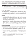
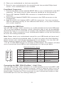
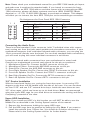
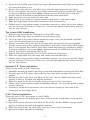
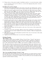
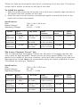
P180B User’s Manual Manuel de l’utilisateur Anwenderhandbuch Manuale per l’operatore Manual del usuario পᡅ䂀ᯢ At Antec, we continually refine and improve our products to ensure the highest quality. So it’s possible that your new case may differ slightly from the descriptions in this manual. This isn’t a problem; it’s simply an improvement. As of the date of publication, all features, descriptions, and illustrations in this manual are correct. Disclaimer This manual is intended only as a guide for Antec’s Computer Enclosures. For more comprehensive instructions on installing the motherboard and peripherals, please refer to the user’s manuals which come with the components and drives. P180B User’s Manual The P180B comes without a power supply. Make sure you choose a power supply that is compatible with and has long enough power harnesses to reach your motherboard and peripheral devices. We recommend our TruePower 2.0, Neo HE or Phantom power supplies for the latest ATX specification compliance, wide compatibility, and power savings capability. Setting Up 1. Place the case upright on a flat, stable surface. 2. Remove the thumbscrew from the left side panel. Grip the panel at the top and bottom and slide it towards you to open the case. Note: Don’t use your fingernail to pry or lift the panels. 3. Remove the screws from the right side panel. Grip the panel at the top and bottom and slide it towards you to remove. 4. Inside the case you should see two separate chambers - the upper chamber for motherboard, external drives and hard drives; and the lower chamber for power supply and hard drives. You will also find some wiring with marked connectors (USB, PWR etc.), and installed I/O panel, a box containing the top fan spoiler and drive rails for 5.25” drives and floppy disk drive, a tool box attached to the upper HDD cage (the inside of the cage) containing more hardware (screws, brass standoffs, spare silicone grommets, etc.) Installing the Motherboard This manual does not cover CPU, RAM, or expansion card installation. Please consult your motherboard manual for specific mounting instructions and troubleshooting. 1. Lay the case down, with the open left side facing up. The drive cages and power supply cage should be visible. 2. Make sure you have the correct I/O panel for your motherboard. If the panel provided with the case isn’t suitable, please contact your motherboard manufacturer for the correct I/O panel. 3. Line up your motherboard with the standoff holes, and remember which holes are lined up. Not all motherboards will match with all the provided holes; this is normal, and won’t affect functionally. (In other words, there will likely be extra holes.) 4. Remove your motherboard by lifting it up. 5. Screw the brass standoffs into the threaded holes that line up with your motherboard. Do not over-tighten the standoffs. Some standoffs may be pre-installed for your convenience. 1 6. Place your motherboard on the brass standoffs. 7. Screw in your motherboard to the standoffs with the provided Philips-head screws. Your motherboard is now installed. Front Bezel Connectors 1. Connect the Reset switch (labeled RESET SW) to your motherboard at the RST connector. The white wire for each connector should be on the ground pin. 2. Power LED (labeled POWER LED) connector is located behind the Reset connector. 3. Power Switch (labeled POWER SW) connects to the PWR connector on the motherboard. 4. Hard Drive LED I & II (labeled HDD I, HDD II) connectors. You may use these LEDs for indicating activity on two different hard drives, or any other indication your system supports. Connecting the USB Ports You will find a single 10-pin connector on a cable attached to the front USB ports. This is an Intel standard connector, which is keyed so that it can’t be accidentally, reversed as long as it is connected to a proper Intel standard motherboard header. Connect the 10-pin connector to your motherboard headers so that the blocked pin fits over the missing header pin. Note: Please check your motherboard manual for your USB header pin layout and make sure it matches the attached table. If it does not match this Intel standard, please contact your motherboard manufacturer for an adapter. You may also call Antec customer support at (800) 22ANTEC (North America) or +31 (0) 10 462-2060 (Europe) to purchase a USB adapter. This adapter will allow you to connect the front USB to your motherboard on a pin-by-pin basis. Motherboard Pin Layout 1 2 9 10 Pin Signal Names Pin Signal Names 1 USB Power 1 2 USB Power 2 3 Negative Signal 1 4 Negative Signal 2 5 Positive Signal 1 6 Positive Signal 2 7 Ground 1 8 Ground 2 9 Key (No Connection) 10 Empty Pin Connecting the IEEE 1394 (FireWire®, i.Link®) Port You will find a single 10-pin connector on a cable attached to the front IEEE 1394 connection. This is an Intel standard connector, which is keyed so that it can’t be accidentally reversed as long as it is connected to a proper Intel standard motherboard header. Connect the 10-pin connector to your motherboard header so that the blocked pin fits over the missing header pin. 2 Note: Please check your motherboard manual for your IEEE 1394 header pin layout and make sure it matches the attached table. If you intend to connect the front FireWire port to an IEEE 1394 add-on card that comes with an external-type IEEE 1394 connector, please call Antec customer service at (800) 22ANTEC (North America) or +31 (0) 10 462-2060 (Europe) to purchase an adapter. This adapter will allow you to connect the front IEEE 1394 port to the external-type connector. Pin Assignment for Front Panel IEEE 1394 Connector 1 2 9 10 Pin Signal Names Pin Signal Names 1 TPA+ 2 TPA– 3 Ground 4 Ground 5 TPB+ 6 TPB– 7 +12V (Fused) 8 +12V (Fused) 9 Key (No Pin) 10 Ground Connecting the Audio Ports There is an Intel standard 10-pin connector (with 7 individual wires with connectors) coming out from the front panel speaker and microphone connection. If your motherboard supports Intel’s standard onboard audio connector, you can plug the 10-pin connector directly onto the board. For non-Intel standard audio connections, you will need to plug the seven individual connectors in as follows: Locate the internal audio connectors from your motherboard or sound card. Consult your motherboard or sound card manual for the pin-out positions. 1. Microphone Signal Pin: Connect the MIC connector to this pin. 2. Microphone Power: Connect the MIC-BIAS connector to this pin. 3. Ground Pin: Connect the AUD GND connector to this pin. 4. Front Right Speaker Out Pin: Connect the FPOUT-R connector to this pin. 5. Front Left Speaker Out Pin: Connect the FPOUT-L connector to this pin. 6. Rear Right Speaker Out Pin: Connect the RET-R connector to this pin. 7. Rear Left Speaker Out Pin: Connect RET-L connector to this pin. 3.5” Device Installation With the front bezel facing you, swing the front door open. It can swing 270 degrees so the door will be parallel with the side of the case. You can see there are four 5.25” and one 3.5” external drive bays. Inside the case there are two 3.5” drive cages, which can house up to six hard drives. Note: we recommend using the lower HDD cage for your hard drives to maximize the cooling and Quiet Computing™ potential of the case. Upper HDD Installation Note: If you install any HDD’s in this location you will NOT be able to use the Middle Fan as described in the Cooling System section of the manual. 1. Remove the thumbscrew holding the upper HDD cage. 2. Pull the HDD cage from its position by pulling the ring. Note: If you want to install the optional front 120mm fan, you should do so before continuing. Please refer to the Cooling System section for further details. 3 3. There are two HDD trays inside the cage. Squeeze the metal clips on each side of a tray and slide it out. 4. Mount your hard drive to the drive tray with the special screws provided. Don’t over-tighten the screws since that could decrease the grommets’ ability to absorb vibration and noise. Note: Always mount the hard drive with the thicker side of the silicone grommets contacting the hard drive. 5. Slide and lock the tray back into the case. 6. Repeat this if you want to mount another hard drive in the upper cage. 7. Slide the cage back to the case and fasten the thumbscrew. 8. Please refer to the power supply installation section to route the power cables to your devices. Once you’ve done so, connect the appropriate power connectors to your device. The Lower HDD Installation. 1. Remove the thumbscrew holding the lower HDD cage. 2. Pull the HDD cage from its position by pulling the ring. 3. You can mount four hard drives inside the cage. They are mounted vertically with silicone grommets on both sides. 4. Mount your hard drive into the drive cage with the special screws provided. (These screws are in the toolbox attached to the back of the upper HDD cage.) Don’t over-tighten the screws since that could decrease the grommets’ ability to absorb vibration and noise. Note: Always mount the HDD with the thicker side of the silicone grommets facing up. 5. Repeat the same procedure for the other drives as necessary. 6. Slide the cage back into the case and fasten the thumbscrew. 7. Please refer to the power supply installation section, to route the power cables to your devices. Once you’ve done so, connect the appropriate power connectors to your device. External 3.5” Drive Installation There is one external 3.5” drive bay. 1. Carefully remove the plastic drive bay cover and metal plate covering the drive bay. 2. Find the pair of 3.5” drive rails from the box that also contains the top fan spoiler. 3. Mount the drive rails onto the sides of the 3.5” device. Make sure the metal portion is facing forward and angled outward. 4. Slide the device into the drive bay until you hear it click into place. 5. Please refer to the power supply installation section, to route the power cables to your devices. 6. Connect a small 4-pin connector from the power supply to the male 4-pin connector on the floppy drive. 5.25” Device Installation There are four 5.25” drive bays in the P180B. 1. Carefully remove the plastic drive bay cover and the metal plate covering the drive bay. 2. Mount the drive rails onto the sides of the 5.25” device. Make sure the metal portion is facing forward and angled outward. 3. Slide the device into the drive bay until you hear it click into place. 4. Mount the other devices accordingly. 4 5. Please refer to the power supply installation section, to route the power cables to your devices. Once you’ve done so, connect the appropriate power connectors to your device. Installing the power supply 1. With the case upright and both side panels removed (see Setting Up), remove the screws on both sides of the power supply retaining cage and pull the cage out. 2. Slide your power supply into the cage, and slide the cage with power supply back into the case. Note: You can mount the power supply either side up, but don’t fasten the power supply and cage to the case at this time. 3. There is a plastic sliding panel assembly between the upper and lower chambers that lets you run power and data cables between the chambers while maintaining thermal isolation. It has two parts, one large and one small, both of which can slide independently to adjust the size of the openings. Loosen the two thumbscrews holding the panels and slide the large panel all the way to the rear of the case to fully expand the opening. 4. Carefully guide all the power cables through the opening to the upper chamber. Route power cables to your installed upper chamber devices and make the appropriate connections. Note: you may want to pull the power cable of the lower chamber 120mm fan to the upper chamber for easy cable management. 5. Now secure the power supply by screwing the retaining cage to the case. Also fasten the power supply to the back of the case at this time with the screws provided. 6. Slide the small plastic divider panel to the rear of the case to fully expand the other opening. 7. Carefully route power and data cables to the lower chamber as necessary for the hard drives you have installed in the lower chamber. Make the appropriate connections. 8. Slide both the large and small plastic panels all the way to the front of the case to close the openings. 9. Tighten the two thumbscrews to secure the sliding panels. Cooling System The Tricool™ fan: The P180B includes three installed 120mm Tricool™ fans. Tricool™ fans have a three-speed switch that lets you choose between quiet, standard or maximum cooling. We set the default fan speed to “Low” for the upper and rear120mm fans. (See specifications below.) Note: The minimum voltage to start the fan is 5V. We recommend our users to set the fan speed to High if you choose to connect the fan to a fan control device or to the Fan-Only connector found on some Antec power supplies. A fan-controlled-device regulates the fan speed by varying the voltage to the fan. The voltage may start as low as 4.5V to 5V. Connecting a Tricool™ set on Medium or Low to a fan-control device may result in the fan not being able to start. The already lowered voltage from the fan control device will be further reduced by the Tricool™ circuitry below 5V. The Top and Rear Exhaust Tricool™ Fans We recommend leaving these two fans at the default Low speed setting as these fans sit right next to your CPU and can effectively exhaust heat from your chassis. If you choose to overclock or install a very hot CPU you can increase the fan speed to achieve better cooling. 5 These two fans are mounted so that the air is blowing out of the case. The top fan comes with a spoiler to mount on the top of the case. To install the spoiler: 1. With the spoiler open end facing the rear of the case, carefully align the tabs of the spoiler with the notches on the case. 2. Insert the tabs into the notches and slide the spoiler towards the front of the case until it clicks into position Specifications: Size: Rated Voltage: Operating Voltage: Speed Input Current 120 x 120 x 25.4 mm DC 12V 10.2V ~ 13.8V Air Flow Static Pressure Acoustical Noise Input Power High 2000 RPM 0.24A (Max.) 2.24 m³ / min (79 CFM) 2.54 mm-H2O (0.10 inch-H2O) 30 dBA 2.9 W Medium 1600 RPM 0.2A 1.59 m³ / min (56 CFM) 1.53 mm-H2O (0.06 inch-H2O) 28 dBA 2.4 W Low 1200 RPM 0.13A 1.1 m³ / min (39 CFM) 0.92 mm-H2O (0.04 inch-H2O) 25 dBA 1.6 W The Lower Chamber Tricool™ Fan This is a special high throughput 120mm fan. Because of its design this fan can move more air than standard 120mm fans at the same speed (RPM). This fan is placed in the middle of the lower chamber, which act likes a wind tunnel when the side panels are closed. Note: we recommend setting the speed to Medium or Low. The default fan setting is “Medium”. Specifications: Size: Rated Voltage: Operating Voltage: Speed Input Current 120 x 120 x 25.0 mm DC 12V 10.2V ~ 13.8V Air Flow Static Pressure Acoustical Noise Input Power High 1500 RPM 0.2A (Max.) 1.70 m³ / min (60 CFM) 2.22 mm-H2O (0.08 inch-H2O) 28 dBA 2.4 W Medium 1200 RPM 0.15A 1.36 m³ / min (48 CFM) 1.42 mm-H2O (0.05 inch-H2O) 23 dBA 1.8 W 0.1A 1.02 m³ / min (36 CFM) 0.80 mm-H2O (0.03 inch-H2O) 17 dBA 1.2 W Low 900 RPM 6 The Optional Fans There are two optional 120mm fan mounts — the front fan (located in front of the upper HDD cage) and the middle fan (located inside the upper HDD cage). These two fans should be installed so that the air is blowing into the case from the front. The Front Fan — The front fan is provided to enhance the HDD cooling of any drives mounted in the upper HDD Cage, or to add airflow within the main chamber. The Middle Fan — The middle fan is designed to cool VGA cards, especially dual VGA card systems. Using this configuration the Upper HDD cage becomes a duct drawing fresh air from the front of the case. You can choose to mount only the middle fan or you can mount both the front and middle fans to further enhance cooling as the two fans will create a push/pull action to bring air in more efficiently. Note: If you add the middle fan, you will not be able to mount hard drives in the upper drive cage. 1. Find the two fan wire brackets insidethe box holding the spoiler and the drive rails. 2. Install the wire brackets in the upper HDD cage as shown 3. Clip the fan into position as shown We strongly recommend NOT installing the optional fans unnecessarily since they will create additional fan noise. However if you insist, we recommend using Antec 120mm TriCool™ fans and setting the speed to low. The Washable Air Filter There are two filters located behind the front grilles. From time to time it will be necessary to wash the installed air filters. Not washing the air filters will result in higher system temperatures and possible operational stability problems. We recommend checking the air filters at least once a month initially. This frequency may change depending on system usage (users whose systems run 24/7 will likely have to check/wash more often than those who don’t use their systems every day) and environmental conditions. To remove the filters: 1. Open the front door. You’ll see 2 fan grilles, one above the external 3.5” drive bay and one below it. 2. Push on the fan grilles on the right middle edge. You’ll hear a click and the grille will pop open part way. Pull the grille open fully. 3. There are two tabs on the filter. Use both of your hands to press the tabs downwards. Lift it up and slide it towards the top of the case to remove the filter. 7 Antec, Inc. 47900 Fremont Blvd. Fremont, CA 94538 USA tel: 510-770-1200 fax: 510-770-1288 Antec Europe B.V. Stuttgartstraat 12 3047 AS Rotterdam The Netherlands tel: +31 (0) 10 462-2060 fax: +31 (0) 10 437-1752 Technical Support: US & Canada 1-800-22ANTEC [email protected] Europe +31 (0) 10 462-2060 [email protected] www.antec.com © Copyright 2006 Antec, Inc. All rights reserved. All trademarks are the property of their respective owners. Reproduction in whole or in part without written permission is prohibited. Printed in China. Version 1.0.1 02/21/2006