1
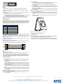
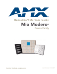
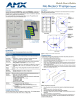
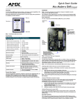
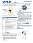
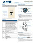
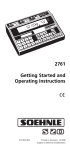
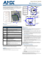
Quick Start Guide
Mio Modero® Classic
Overview
Installation Button
The Mio Modero Classic (FG5795-01xx, single style; FG5795-02xx, double style; xx
indicates color selection) provides a wide range of control capabilities in the form of
keypads that are as adept as they are elegant. Each device is available as single style
(8 button max) or double style (16 button max).
You need KeypadBuilder to properly program these devices. The application and
documentation are available from www.amx.com.
AXlink
3.5 mini Phoenix
connector
Slot to pry
button free
PWR+
Screw
holes
Mounting Frame
8 position mini
DIP switch
Notch to pry
faceplate free
(Rear Single)
(Front Single)
8 position mini
DIP switch
AXlink
3.5 mini Phoenix
connector
Screw
holes
PWR+
Classic
Installation Buttons
Face Plate
Notch to pry
faceplate free
FIG. 1 Mio Modero Single Style Classic
Specifications
The Mio Modero device family keypad specifications are as follows:
(Rear Double)
Specifications
FIG. 2 Mio Modero Front and Rear Components
Power:
12 vDC, 70 - 230 mA (range depending on device type and number of
buttons)
Changing Buttons
Front Panel
Components:
• Pushbuttons - a maximum of 8 buttons on the single style and 16
buttons on the double style, with a direct LED light.
Rear Panel
Components:
• DIP switch - 8 position mini DIP switch used to set the device address
for the keypad on the AXlink Bus.
• Wiring connection - 4 pin 3.5mm Phoenix AXlink connector.
Dimensions
(HWD):
• Single style - 4.46" x 2.71" x .57" (113.28 mm x 68.83 mm x 14.48 mm)
• Double style - 4.46" x 4.39" x .57" (113.28 mm x 111.51 mm x 14.48
mm)
Weight
(range):
.25 lbs (.11 kg) - .50 lbs (.23 kg) Style and number of buttons will decide
weight.
Operating
Environment:
• Operating Temperature: 0° to 50° C (32° to 122° F)
• Storage Temperature: -10° to 70° C (14° to 158° F)
Mounting:
Mounts into US and a majority of International single gang back boxes.
Included
Accessories:
•
•
•
•
Optional
Accessories:
• Accent Frame (for some larger wallboxes):
Classic (xx indicates color selection) FG5795-08xx (single button); FG5795-09xx (double button)
• Custom buttons:
Classic Colors (xx indicates color selection) - FG5795-21xx (4
single buttons); FG5795-22xx (2 double buttons)
• Blank buttons:
Classic Colors (xx indicates color selection) - FG5795-07xx
Single style mounting kit (KA-5795-01)
Double style mounting kit (KA-5795-02)
Installation Buttons (Classic only)
Phoenix Connector (41-5045)
Available Color Schemes
The Mio Modero device family is available in a range of colors. The Classic supports
these color schemes, Black (BL), White (WH), and Beige (BG).
Installation
Note: Before touching the device, discharge the static electricity from your body by
touching a grounded metal object.
The basic front and rear components of the Mio Modero are as follows:
The Mio Modero Classic is shipped with "installation" buttons; they are intended to be
place holders until your engraved buttons, designed with KeypadBuilder, arrive.
To switch out "installation" buttons:
1.
2.
3.
Pry the button using the slot on the front of the "installation" buttons to remove
them from the Mio Modero.
Select the location of the custom buttons and snap them into place. Be sure to
note the orientation of the white insert on the back of the button, the notch must
be down. Insert the bottom of the button first and then push the top into place.
Snap the faceplate on the mounting frame.
To change custom buttons:
1.
2.
If connected, disconnect the power supply.
If connected to mounting frame, place a flathead screwdriver in the notch at the
bottom right of the Mio Modero, and pry the faceplate from the mounting frame.
3.
On the back of the faceplate locate the button access points, outlined with white
circles. Using a straightened paperclip, poke through the button access points
until the buttons pop free.
4.
Snap the desired custom buttons into place. Be sure to note the orientation of
the white insert on the back of the button, the notch must be down. Insert the
bottom of the button first and then push the top into place.
5.
If the power supply was disconnected in Step 1, reconnect and return power to
the device.
6.
Snap the faceplate on the mounting frame.
Be certain to reprogram the Mio Modero to match the new button arrangement; use
KeypadBuilder to assign the locations. See the KeypadBuilder Instruction Manual
available at www.amx.com.
Setting The AXlink Device Number
1.
2.
3.
If connected, disconnect the power supply.
Locate the 8-position Device DIP switch on the rear panel.(FIG. 3).
Set the DIP switch according to the switch values shown below.
Switch
1
2
3
4
5
6
7
8
Value
1
2
4
8
16
32
64
128
The device number is set by the total value of DIP switch positions that are
ON (up).
As an example, the DIP switch in FIG. 3 defines device number 129
(1+128=129).
If you later change the device number, remove and reconnect the AXlink power
connector to enter the new device number into memory.
Note: AMX has created Dip Switch2 to assist in calculating dip switch position values.
Download the program Dip Switch2 from www.amx.com for free.
Podium Mounting
1.
FIG. 3 Example Device DIP Switch set to 129
Wiring
The Mio Modero uses a four-pin mini AXlink connector for power and data.
Caution: Do not connect power to the Mio Modero until the wiring is complete.
Preparing captive wires
You will need a wire stripper, and flat-blade screwdriver to prepare and connect the
captive wires.
1.
Strip 0.25 inch (6.35 mm) of wire insulation off all wires.
2.
Insert each wire into the appropriate opening on the connector according to the
wiring diagrams and connector types described in this section.
3.
Turn the flat-head screws clockwise to secure the wires in the connector.
Note: Do not over-torque the screws; doing so can bend the seating pins and
damage the connector.
The necessary area for the mounting frame opening is 2.00 x 2.25; cutout the
mounting frame install surface to accommodate the Mio Modero.
2.
Confirm that the terminal end of the AXlink cable is disconnected, and not
receiving power.
3.
If the faceplate is connected to the mounting frame, place a flathead screwdriver in the notch at the bottom right of the Mio Modero, and pry the faceplate
from the mounting frame.
4.
With the mounting frame resting in the cutout area, drill the mounting holes into
the flat surface.
Note: Do not overtighten the screws when mounting the mounting frame. The device
should be flush with mounting surface.
5.
Connect the AXlink power supply. The connector passes through the center of
the mounting frame and connects to the board. The connection is illustrated in
FIG. 2.
6.
Attach the faceplate to the mounting frame first at the top and swing it to the
bottom. See FIG. 5.
Wiring guidelines
The Mio Modero requires 12 VDC power to operate properly. The necessary power
is supplied via the AXlink cable. The maximum AXlink wiring distance is determined
by power consumption, supplied voltage, and the wire gauge used for the cable. The
following table lists wire sizes and the maximum lengths allowable based on the
maximum power consumption rating of 170 mA.
Wiring Guidelines at 170 mA
Wire Size
Maximum Wiring Length
18 AWG
690.42 feet (210.43 m)
20 AWG
436.80 feet (133.13 m)
22 AWG
272.33 feet (83.00 m)
24 AWG
171.66 feet (52.32 m)
FIG. 5 Attaching the faceplate to the mounting frame
The maximum wiring lengths for using AXlink power are based on a minimum of 13.5
volts available. If the distance is greater than what is listed in the table, consult the
Mio Modero Device Family Instruction Manual for wiring with external power sources.
Connecting the Wiring
Caution: If using power from AXlink, disconnect the wiring from the control system
before wiring the Mio Modero.
Programming The Mio Modero
KeypadBuilder
Most functionality of the Mio Modero is handled using the application, KeypadBuilder.
Go to www.amx.com for the KeypadBuilder Instruction Manual.
There are a select number or SEND_COMMANDs the Mio Modero recognizes. For a
full list and descriptions, consult the Mio Modero Device Family Instruction Manual.
AXlink Data and Power Connections
Connect the control system's AXlink connector to the AXlink connector on the rear
panel of the Mio Modero for data and 12 VDC power as shown in FIG. 4.
PWR +
PWR +
AXP
AXP
AXM
AXM
GND -
GND -
Mio Modero
Control System
FIG. 4 AXlink wiring
Mounting Procedures
AMX recommends mounting the Mio Modero in a standard one-gang wallbox, a
conduit box per NEC specs section 370, with a minimum internal clearance of 2-5/8"
x 1-3/4" x 1-5/8" (HWD), but it is possible to mount the Mio Modero to a podium
without a wallbox. More installation details are available in the Mio Modero Device
Family instruction manual.
Wallbox Mounting
1.
Use the cutout dimension for the wallbox to cutout the install surface for the
Mio Modero.
2.
Confirm that the terminal end of the AXlink cable is disconnected, and not
receiving power.
3.
If the faceplate is connected to the mounting frame, place a flathead screwdriver in the notch at the bottom right of the Mio Modero, and pry the faceplate
from the mounting frame.
4.
Connect the AXlink power supply. The connector passes through the center of
the mounting frame and connects to the board. The connection is illustrated in
FIG. 2.
5.
Place the mounting frame on the wallbox; align the screw holes with the mounting holes on the panel, and fasten the mounting frame to the wallbox using the
screws supplied.
Note: Do not overtighten the screws when mounting the mounting frame. The device
should be flush with mounting surface.
6.
Attach the faceplate to the mounting frame first at the top and swing it to the
bottom. See FIG. 5
For full warranty information, refer to the AMX Instruction Manual(s) associated with your Product(s).
8/06
©2007 AMX. All rights reserved. AMX and the AMX logo are registered trademarks of AMX.
AMX reserves the right to alter specifications without notice at any time.
3000 RESEARCH DRIVE, RICHARDSON, TX 75082 • 800.222.0193 • fax 469.624.7153 • technical support 800.932.6993 • www.amx.com
93-5795
REV: J