1
USER GUIDE
SMCWBR14-N
Barricade™ N
2.4GHz Draft 11n
Wireless 4-port Broadband Router
LIMITED WARRANTY
Limited Warranty Statement: SMC Networks, Inc. (“SMC”) warrants its products to be free from
defects in workmanship and materials, under normal use and service, for the applicable warranty
term. All SMC products carry a standard 90-day limited warranty from the date of purchase from
SMC or its Authorized Reseller. SMC may, at its own discretion, repair or replace any product not
operating as warranted with a similar or functionally equivalent product, during the applicable
warranty term. SMC will endeavor to repair or replace any product returned under warranty within 30
days of receipt of the product. The standard limited warranty can be upgraded to a Limited Lifetime*
warranty by registering new products within 30 days of purchase from SMC or its Authorized
Reseller. Registration can be accomplished via the enclosed product registration card or online via
the SMC website. Failure to register will not affect the standard limited warranty. The Limited
Lifetime warranty covers a product during the Life of that Product, which is defined as the period of
time during which the product is an “Active” SMC product. A product is considered to be “Active”
while it is listed on the current SMC price list. As new technologies emerge, older technologies
become obsolete and SMC will, at its discretion, replace an older product in its product line with one
that incorporates these newer technologies. At that point, the obsolete product is discontinued and is
no longer an “Active” SMC product. A list of discontinued products with their respective dates of
discontinuance can be found at: http://www.smc.com/index.cfm?action=customer_service_warranty.
All products that are replaced become the property of SMC. Replacement products may be either
new or reconditioned. Any replaced or repaired product carries either a 30-day limited warranty or
the remainder of the initial warranty, whichever is longer. SMC is not responsible for any custom
software or firmware, configuration information, or memory data of Customer contained in, stored
on, or integrated with any products returned to SMC pursuant to any warranty. Products returned to
SMC should have any customer-installed accessory or add-on components, such as expansion
modules, removed prior to returning the product for replacement. SMC is not responsible for these
items if they are returned with the product. Customers must contact SMC for a Return Material
Authorization number prior to returning any product to SMC. Proof of purchase may be required.
Any product returned to SMC without a valid Return Material Authorization (RMA) number clearly
marked on the outside of the package will be returned to customer at customer’s expense. For
warranty claims within North America, please call our toll-free customer support number at (800)
762-4968. Customers are responsible for all shipping charges from their facility to SMC. SMC is
responsible for return shipping charges from SMC to customer.
WARRANTIES EXCLUSIVE: IF AN SMC PRODUCT DOES NOT OPERATE AS WARRANTED
ABOVE, CUSTOMER’S SOLE REMEDY SHALL BE REPAIR OR REPLACEMENT OF THE
PRODUCT IN QUESTION, AT SMC’S OPTION. THE FOREGOING WARRANTIES AND
REMEDIES ARE EXCLUSIVE AND ARE IN LIEU OF ALL OTHER WARRANTIES OR
CONDITIONS, EXPRESS OR IMPLIED, EITHER IN FACT OR BY OPERATION OF LAW,
STATUTORY OR OTHERWISE, INCLUDING WARRANTIES OR CONDITIONS OF
MERCHANTABILITY AND FITNESS FOR A PARTICULAR PURPOSE. SMC NEITHER ASSUMES
NOR AUTHORIZES ANY OTHER PERSON TO ASSUME FOR IT ANY OTHER LIABILITY IN
CONNECTION WITH THE SALE, INSTALLATION, MAINTENANCE OR USE OF ITS PRODUCTS.
SMC SHALL NOT BE LIABLE UNDER THIS WARRANTY IF ITS TESTING AND EXAMINATION
DISCLOSE THE ALLEGED DEFECT IN THE PRODUCT DOES NOT EXIST OR WAS CAUSED BY
CUSTOMER’S OR ANY THIRD PERSON’S MISUSE, NEGLECT, IMPROPER INSTALLATION OR
TESTING, UNAUTHORIZED ATTEMPTS TO REPAIR, OR ANY OTHER CAUSE BEYOND THE
RANGE OF THE INTENDED USE, OR BY ACCIDENT, FIRE, LIGHTNING, OR OTHER HAZARD.
LIMITATION OF LIABILITY: IN NO EVENT, WHETHER BASED IN CONTRACT OR TORT
(INCLUDING NEGLIGENCE), SHALL SMC BE LIABLE FOR INCIDENTAL, CONSEQUENTIAL,
INDIRECT, SPECIAL, OR PUNITIVE DAMAGES OF ANY KIND, OR FOR LOSS OF REVENUE,
i
LOSS OF BUSINESS, OR OTHER FINANCIAL LOSS ARISING OUT OF OR IN CONNECTION
WITH THE SALE, INSTALLATION, MAINTENANCE, USE, PERFORMANCE, FAILURE, OR
INTERRUPTION OF ITS PRODUCTS, EVEN IF SMC OR ITS AUTHORIZED RESELLER HAS
BEEN ADVISED OF THE POSSIBILITY OF SUCH DAMAGES. SOME STATES DO NOT ALLOW
THE EXCLUSION OF IMPLIED WARRANTIES OR THE LIMITATION OF INCIDENTAL OR
CONSEQUENTIAL DAMAGES FOR CONSUMER PRODUCTS, SO THE ABOVE LIMITATIONS
AND EXCLUSIONS MAY NOT APPLY TO YOU. THIS WARRANTY GIVES YOU SPECIFIC LEGAL
RIGHTS, WHICH MAY VARY FROM STATE TO STATE. NOTHING IN THIS WARRANTY SHALL
BE TAKEN TO AFFECT YOUR STATUTORY RIGHTS.
* SMC will provide warranty service for one year following discontinuance from the active
SMC price list. Under the limited lifetime warranty, internal and external power supplies, fans,
and cables are covered by a standard one-year warranty from date of purchase.
SMC Networks, Inc.
38 Tesla
Irvine, CA 92618
ii
Compliances
Federal Communication Commission Interference Statement
This equipment has been tested and found to comply with the limits for a Class B digital device,
pursuant to Part 15 of the FCC Rules. These limits are designed to provide reasonable protection
against harmful interference in a residential installation. This equipment generates, uses and can
radiate radio frequency energy and, if not installed and used in accordance with the instructions,
may cause harmful interference to radio communications. However, there is no guarantee that
interference will not occur in a particular installation. If this equipment does cause harmful
interference to radio or television reception, which can be determined by turning the equipment off
and on, the user is encouraged to try to correct the interference by one or more of the following
measures:
• Reorient or relocate the receiving antenna.
• Increase the distance between the equipment and receiver.
• Connect the equipment into an outlet on a circuit different from that to which the receiver is
connected.
• Consult the dealer or an experienced radio/TV technician for help.
FCC Caution: To assure continued compliance, (example - use only shielded interface cables when
connecting to computer or peripheral devices) any changes or modifications not expressly approved
by the party responsible for compliance could void the user’s authority to operate this equipment.
This device complies with Part 15 of the FCC Rules. Operation is subject to the following two
conditions: (1) This device may not cause harmful interference, and (2) this device must accept any
interference received, including interference that may cause undesired operation.
IMPORTANT NOTE
FCC Radiation Exposure Statement:
This equipment complies with FCC radiation exposure limits set forth for an uncontrolled
environment. This transmitter must not be co-located or operating in conjunction with any other
antenna or transmitter.
CE Mark Declaration of Conformance for EMI and Safety (EEC)
This device complies with the essential requirements of the R&TTE Directive 1999/5/EC.
The following references have been applied in order to prove presumption of compliance with the
R&TTE Directive 1999/5/EC:
• EN 300 328
• EN 301 489-1
• EN 301 489-17
• EN 60950-1
iii
Table of Contents
Getting Started with the SMCWBR14-N
Package Contents
Minimum System Requirements
3
4
4
Wireless LAN Networking
5
Introduction
Features
9
9
Hardware Overview
Rear Panel
LEDs
Installation Considerations
Getting Started
10
10
11
12
12
Using the Configuration Menu
Basic
Advanced
Tools
Status
13
14
24
53
70
Glossary
79
2
Getting Started with the SMCWBR14-N
Congratulations on purchasing the SMCWBR14-N. This manual provides information for setting
up and configuring the SMCWBR14-N. This manual is intended for both home users and
professionals.
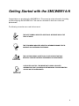
The following conventions are used in this manual:
THE NOTE SYMBOL INDICATES ADDITIONAL INFORMATION ON THE
TOPIC AT HAND.
THE TIP SYMBOL INDICATES HELPFULL INFORMATION AND TIPS TO
IMPROVE YOUR NETWORK EXPERIENCE.
THE CAUTION SYMBOL ALERTS YOU TO SITUATIONS THAT MAY
DEGRADE YOUR NETWORKING EXPERIENCE OR COMPROMISE
LIKE NOTES AND TIPS, THE IMPORTANT SYMBOL INDICATES
INFORMATION THAT CAN IMPROVE NETWORKING. THIS INFORMATION
SHOULD NOT BE OVERLOOKED.
3
Package Contents
z
Barricade™ N Broadband Router (SMCWBR14-N)
z
Yellow RJ-45 Ethernet Cable
z
Power Adapter (5.0V, 2.5A)
z
Documentation CD
z
Quick Installation Guide
z
Warranty registration card
Using a power supply with a different voltage than the one included with your
product will cause damage and void the warranty for this product.
Minimum System Requirements
z
Broadband (Cable/xDSL) Internet service and Modem with Ethernet connection.
z
2.4GHz 802.11n draft wireless adapter or 2.4GHz 802.11b/g wireless adapter installed on
each PC. Alternatively an Ethernet adapter can be used.
z
Internet Explorer 5.5 or above, Netscape 4.7 or above, Mozilla Firefox 1.0 or above
4
Wireless LAN Networking
This section provides background information on wireless LAN networking technology. Consult
the Glossary for definitions of the terminology used in this section.
THE INFORMATION IN THIS SECTION IS FOR YOUR REFERENCE. CHANGING
NETWORK SETTINGS AND PARTICULARLY SECURITY SETTTINGS SHOULD ONLY
BE DONE BY AN AUTHORIZED ADMINISTRATOR.
Transmission Rate (Transfer Rate)
The SMCWBR14-N provides various transmission (data) rate options for you to select. In most
networking scenarios, the factory default Best (automatic) setting proves the most efficient. This
setting allows your SMCWBR14-N to operate at the maximum transmission (data) rate. When the
communication quality drops below a certain level, the SMCWBR14-N automatically switches to a
lower transmission (data) rate. Transmission at lower data speeds is usually more reliable.
However, when the communication quality improves again, the SMCWBR14-N gradually increases
the transmission (data) rate again until it reaches the highest available transmission rate.
Types of Wireless Networks
Wireless LAN networking works in either of the two modes: ad-hoc and infrastructure. In infrastructure mode, wireless devices communicate to a wired LAN via access points. Each access
point and its wireless devices are known as a Basic Service Set (BSS). An Extended Service Set
(ESS) is two or more BSSs in the same subnet. In ad hoc mode (also known as peer-to-peer
mode), wireless devices communicate with each other directly and do not use an access point.
This is an Independent BSS (IBSS).
To connect to a wired network within a coverage area using access points, set the operation mode
to Infrastructure (BSS). To set up an independent wireless workgroup without an access point, use
Ad-hoc (IBSS) mode.
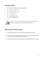
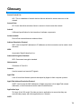
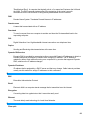
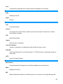
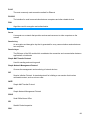
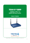
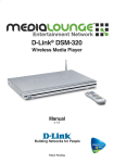
A D -H OC (IBSS) N ETWORK
Ad-hoc mode does not require an access point or a wired network. Two or more wireless stations
communicate directly to each other. An ad-hoc network may sometimes be referred to as an
Independent Basic Service Set (IBSS).
To set up an ad-hoc network, configure all the stations in ad-hoc mode. Use the same SSID and
channel for each station.
5
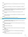
6
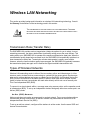
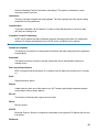
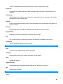
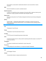
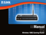
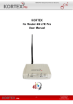
When a number of wireless stations are connected using a single access point, you have a Basic
Service Set (BSS).
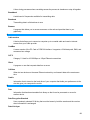
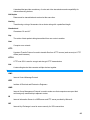
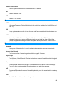
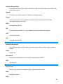
In the ESS diagram below, communication is done through the access points, which relay data
packets to other wireless stations or devices connected to the wired network. Wireless stations
can then access resources, such as a printer, on the wired network.
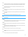
7
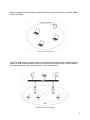
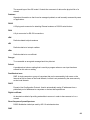
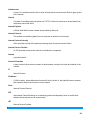
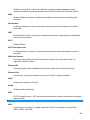
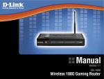
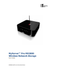
In an ESS environment, users are able to move from one access point to another without losing the
connection. In the diagram below, when the user moves from BSS (1) to BSS (2) the WLAN client
devices automatically switches to the channel used in BSS (2).
Roaming in an ESS network diagram
8
Introduction
The SMCWBR14-N is a high-performance, wireless router that supports high-speed wireless
networking at home, at work or in public places.
Unlike most routers, the SMCWBR14-N provides data transfers at up to 300Mbps when using 11n
(Draft) connection. This router is also backwards compatible with 802.11g or 11b devices. This means
that you do not need to change your entire network to maintain connectivity. You may sacrifice some
of 11n’s (Draft) speed when you mix 11n (Draft) and 11b/g devices, but you will not lose the ability to
communicate when you incorporate the 11n (Draft) standard into your 11b/g network. You may
choose to slowly change your network by gradually replacing the 11b/g devices with 11n (Draft)
devices.
Features
¾
Wi-Fi Compliant with IEEE 802.11n (draft) and IEEEE 802.11b/g Standards
¾
2.412 to 2.484GHz frequency band operation
¾
Compliant with IEEE 802.3 & 3u standards
¾
Support OFDM and CCK modulation
¾
High-Speed up to 300Mbps Data Rate using IEEE 802.11n (draft) connection
¾
Supports Cable/DSL Modems with Dynamic IP, Static IP, PPPoE, PPTP, L2TP or BigPond
Connection Types
¾
Firewall features Network Address Translation (NAT), and Stateful Packet Inspection (SPI)
protects against Dos attacks
¾
Traffic Control with Virtual Server (max 64 configurable servers) and DMZ
¾
UPnP (Universal Plug & Play) and ALGs Support for Internet applications such as Email, FTP,
Gaming, Remote Desktop, Net Meeting, Telnet, and more
¾
Provides Additional Security of Enable/Disable SSID, Internet Access Control (Services, URL and
MAC Filtering)
¾
Supports Multiple and Concurrent IPSec, L2TP and PPTP VPN Pass-Through Sessions
¾
Flash Memory for Firmware Upgrade, Save/Restore Settings
¾
Easy Management via Web Browser (HTTP) and Remote Management
¾
Supports 64/128-bit WEP, WPA/WPA2, and WPA-PSK/WPA2-PSK
¾
Compliant with Windows 98/NT/2000/XP/2003 Server, Linux and Mac OS
¾
Support 4 x 10/100Mbps Auto-MDIX LAN Port and 1 x 10/100Mbps WAN Port (Internet)
¾
Built-in 3 External Antennas to support high speed performance and great coverage
9
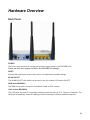
Hardware Overview
Back Panel
POWER
The Power input connector is a single jack socket to supply power to the SMCWBR14-N.
Please use the Power Adapter provided in the SMCWBR14-N package.
RESET
Pressing the reset button restores the router to its original factory default settings.
WLAN ON/OFF
The WLAN ON/OFF slide switch can be used to turn the wireless AP function ON/OFF
WAN (Auto MDI/MDIX)
The WAN port is used to connect to an Ethernet Cable or xDSL modem
LAN1-4 (Auto MDI/MDIX)
The LAN ports are used for connecting networking devices such as PC’s, Printers & Switches. The
LAN ports automatically sense the cable type when connecting to Ethernet enabled computers.
10
Front Panel LED’s
POWER
A solid green LED indicates the SMCWBR14-N is receiving power – normal operation. If the LED is off
there is no power to device or failure.
LAN1-4
A solid green LED indicates the corresponding LAN port connection is established. The LED blinks
when data is transmitted. If the LED is off there is no link for corresponding LAN port.
WAN
A solid green LED indicates the WAN port connection is established. The LED blinks when data
is transmitted. If the LED is off there is no link for the WAN port.
WLAN
A solid green LED indicates the wireless AP is ready. The LED blinks when wireless data is
transmitted.
11
Installation Considerations
The SMCWBR14-N lets you access your network, using a wireless connection, from virtually
anywhere within its operating range. Keep in mind, however, that the number, thickness and location
of walls, ceilings, or other objects that the wireless signals must pass through, may limit the range.
Typical ranges vary depending on the types of materials and background RF (radio frequency) noise
in your home or business. The key to maximizing wireless range is to follow these basic guidelines:
1
Keep the number of walls and ceilings between the SMCWBR14-N and other network devices
to a minimum - each wall or ceiling can reduce your wireless product’s range from 3-90 feet
(1-30 meters.) Position your devices so that the number of walls or ceilings is minimized.
2
Be aware of the direct line between network devices. A wall that is 1.5 feet thick (.5 meters), at
a 45-degree angle appears to be almost 3 feet (1 meter) thick. At a 2-degree angle it looks
over 42 feet (14 meters) thick! Position devices so that the signal will travel straight through a
wall or ceiling (instead of at an angle) for better reception.
3
Building Materials can impede the wireless signal - a solid metal door or aluminum studs may
have a negative effect on range. Try to position wireless devices and computers with wireless
adapters so that the signal passes through drywall or open doorways and not other materials.
4
Keep your product away (at least 3-6 feet or 1-2 meters) from electrical devices or appliances
that generate extreme RF noise.
Getting Started
For a typical home setup, you will need a Broadband (Cable/xDSL) Internet service and Modem
with Ethernet connection. Consult with your Cable or xDSL provider for proper installation of the
modem. Please do the following:
1. Connect your Broadband modem (Cable/xDSL) to the blue WAN port on the Barricade™
2. Connect the network card of your PC to the yellow LAN port on the Barricade™ using the
yellow RJ-45 cable provided. Now connect the power adapter.
3. Reboot PC. Start web browser and enter address http://192.168.2.1. When prompted enter
password smcadmin then click [Log In]. Note: The User Name must be set to Admin.
4. Click [BASIC], then [Setup Wizard], then [Launch Internet Connection Setup Wizard]. Follow
the on screen instructions to complete the set-up and reboot the Barricade™. You are now
ready to enjoy your Internet connection.
12
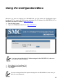
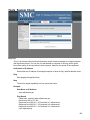
Using the Configuration Menu
Whenever you want to configure your SMCWBR14-N, you can access the Configuration Menu
through your PC by opening the Web-browser and typing in the IP Address of the SMCWBR14-N. The
SMCWBR14-N default IP address is: http://192.168.2.1
¾
¾
Open the Web browser.
Type in the IP Address of the Router (http://192.168.2.1).
If you have changed the default IP Address assigned to the SMCWBR14-N, make sure
you enter the correct IP Address.
¾
¾
¾
Select Admin in the User Name field.
Enter Password: smcadmin (default).
Click Log In.
If you have changed the default password assigned to the SMCWBR14-N, make sure you
enter the correct password.
13
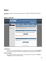
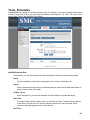
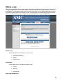
Basic
The Basic tab provides the following configuration options: INTERNET, WIRELESS and NETWORK
SETTINGS.
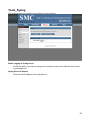
Basic_Internet
Setup Wizard
If you are new to networking and have never configured a router before, click on Setup Wizard
and the router will guide you through a few simple steps to get your network up and running.
Manual Configure
If you consider yourself an advanced user and have configured a router before, click Manual
Configure to input all the settings manually.
14
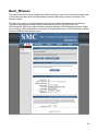
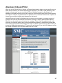
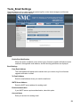
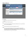
Basic_Wireless
The wireless section is used to configure the wireless settings for your router. Note that changes made
in this section may also need to be duplicated on wireless clients that you want to connect to your
wireless network.
To protect your privacy, use the wireless security mode to configure the wireless security features.
This device supports three wireless security modes including: WEP, WPA-Personal, and
WPA-Enterprise. WEP is the original wireless encryption standard. WPA-Enterprise provides a higher
level of security. WPA-Personal does not require an authentication server. The WPA-Enterprise option
requires a RADIUS authentication server.
15
Enable Wireless
This option allows you to enable/disable the wireless AP function. The wireless can also be
turned ON/OFF by the slide switch on the back panel. When the wireless is enabled, the
following parameters are in effect.
Wireless Network Name
When you are browsing for available wireless networks, this is the name that will appear in the
list (unless Visibility Status is set to Invisible, see below). This name is also referred to as the
SSID. For security purposes, it is highly recommended to change from the pre-configured
network name.
Enable Auto Channel Scan
If you select this option, the router automatically finds the channel with least interference and
uses that channel for wireless networking. If you disable this option, the router uses the
channel that you specify with the following Wireless Channel option.
Wireless Channel
A wireless network uses specific channels in the wireless spectrum to handle communication
between clients. Some channels in your area may have interference from other electronic
devices. Choose the clearest channel to help optimize the performance and coverage of your
wireless network.
802.11 Mode
If all of the wireless devices you want to connect with this router can connect in the same
transmission mode, you can improve performance slightly by choosing the appropriate "Only"
mode. If you have some devices that use a different transmission mode, choose the
appropriate "Mixed" mode.
Channel Width
The "Auto 20/40 MHz" option is usually best. The other options are available for special
circumstances. Note that when 20/40MHz option is selected, an extended channel will be used
to extend the data rate.
Transmission Rate
By default the fastest possible transmission rate will be selected. You have the option of
selecting the speed if necessary.
Visibility Status
The Invisible option allows you to hide your wireless network. When this option is set to Visible,
your wireless network name is broadcast to anyone within the range of your signal. If you're not
using encryption then they could connect to your network. When Invisible mode is enabled,
you must enter the Wireless Network Name (SSID) on the client manually to connect to the
network.
Security Mode (NONE, WEP, WPA-Personal, WPA-Enterprise)
Unless one of these encryption modes is selected, wireless transmissions to and from your
wireless network can be easily intercepted and interpreted by unauthorized users.
WEP
A method of encrypting data for wireless communication intended to provide the same level of
privacy as a wired network. WEP is not as secure as WPA encryption. To gain access to a
16
WEP network, you must know the key. The key is a string of characters that you create. When
using WEP, you must determine the level of encryption. The type of encryption determines the
key length. 128-bit encryption requires a longer key than 64-bit encryption. Keys are defined by
entering in a string in HEX (hexadecimal - using characters 0-9, A-F) or ASCII (American
Standard Code for Information Interchange - alphanumeric characters) format. ASCII format is
provided so you can enter a string that is easier to remember. The ASCII string is converted to
HEX for use over the network. Four keys can be defined so that you can change keys easily. A
default key is selected for use on the network.
Example:
64-bit hexadecimal keys are exactly 10 characters in length. (12345678FA is a valid string
of 10 characters for 64-bit encryption.)
128-bit hexadecimal keys are exactly 26 characters in length.
(456FBCDF123400122225271730 is a valid string of 26 characters for 128-bit
encryption.)
64-bit ASCII keys are up to 5 characters in length (DMODE is a valid string of 5
characters for 64-bit encryption.)
128-bit ASCII keys are up to 13 characters in length (2002HALOSWIN1 is a valid string of
13 characters for 128-bit encryption.)
Note that, if you enter fewer characters in the WEP key than required, the remainder of the key
is automatically padded with zeros.
WPA-Personal and WPA-Enterprise
Both of these options select some variant of Wi-Fi Protected Access (WPA) -- security
standards published by the Wi-Fi Alliance. The WPA Mode further refines the variant that the
router should employ.
WPA Mode: WPA is the older standard; select this option if the clients that will be used with
the router only support the older standard. WPA2 is the newer implementation of the stronger
IEEE 802.11i security standard. With the "WPA or WPA2" option, the router tries WPA2 first,
but falls back to WPA if the client only supports WPA. The strongest cipher that the client
supports will be used. With the "WPA2 Only" option, the router associates only with clients that
also support WPA2 security. If the clients support the AES cipher, it will be used across the
wireless network to ensure best security.
Group Key Update Interval: The amount of time before the group key used for broadcast and
multicast data is changed.
WPA-Personal
This option uses Wi-Fi Protected Access with a Pre-Shared Key (PSK).
Pre-Shared Key: The key is entered as a pass-phrase of up to 63 alphanumeric characters in
ASCII (American Standard Code for Information Interchange) format at both ends of the
wireless connection. It cannot be shorter than eight characters, although for proper security it
needs to be of ample length and should not be a commonly known phrase. This phrase is used
to generate session keys that are unique for each wireless client.
Example:
Wireless Networking technology enables ubiquitous communication
WPA-Enterprise
17
This option works with a RADIUS Server to authenticate wireless clients. Wireless clients
should have established the necessary credentials before attempting to authenticate to the
Server through this Gateway. Furthermore, it may be necessary to configure the RADIUS
Server to allow this Gateway to authenticate users.
Authentication Timeout: Amount of time before a client will be required to re-authenticate.
RADIUS Server IP Address: The IP address of the authentication server.
RADIUS Server Port: The port number used to connect to the authentication server.
RADIUS Server Shared Secret: A pass-phrase that must match with the authentication
server.
MAC Address Authentication: If this is selected, the user must connect from the same
computer whenever logging into the wireless network.
Advanced:
Optional Backup RADIUS Server
This option enables configuration of an optional second RADIUS server. A second
RADIUS server can be used as backup for the primary RADIUS server. The second
RADIUS server is consulted only when the primary server is not available or not
responding. The fields Second RADIUS Server IP Address, RADIUS Server Port,
Second RADIUS server Shared Secret, Second MAC Address Authentication provide
the corresponding parameters for the second RADIUS Server.
18
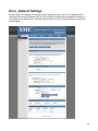
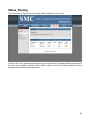
Basic_Network Settings
Use this section to configure the internal network settings of your router. The IP Address that is
configured here is the IP Address that you use to access the Web-based management interface. If
you change the IP Address here, you may need to adjust your PC’s network settings to access the
network again.
19
Router Settings
These are the settings of the LAN (Local Area Network) interface for the router. The router's
local network (LAN) settings are configured based on the IP Address and Subnet Mask
assigned in this section. The IP address is also used to access this Web-based management
interface. It is recommended that you use the default settings if you do not have an existing
network.
IP Address
The IP address of your router on the local area network. Your local area network settings
are based on the address assigned here. For example, 192.168.2.1.
Subnet Mask
The subnet mask of your router on the local area network.
Local Domain Name
This entry is optional. Enter a domain name for the local network. The router's DHCP
server will give this domain name to the computers on the wireless LAN. So, for example,
if you enter mynetwork.net here, and you have a wireless laptop with a name of chris,
that laptop will be known as chris.mynetwork.net. Note, however, if the router's settings
specify "DHCP (Dynamic)" Address, and the router's DHCP server assigns a domain
name to the AP, that domain name will override any name you enter here.
DNS Relay
When DNS Relay is enabled, the router plays the role of a DNS server. DNS requests
sent to the router are forwarded to the ISP's DNS server. This provides a constant DNS
address that LAN computers can use, even when the router obtains a different DNS
server address from the ISP upon re-establishing the WAN connection. You should
disable DNS relay if you implement a LAN-side DNS server as a virtual server.
RIP (Routing Information Protocol)
Used to broadcast routing information among routers.
Enable RIP
Enable RIP if required by the ISP, if the LAN has multiple routers, or if the LAN has
auto-IP devices.
RIP Operating mode
This router supports both version 2 and version 1 of the RIP specification.
V1. Use if none of the routers supports Version 2.
V2 Broadcast. Use if some routers are capable of Version 2, but some are only capable
of Version 1.
V2 Multicast. Use if this is the only router on the LAN or if all the routers support Version
2.
Router Metric
The additional cost of routing a packet through this router. The normal value for a simple
network is 1. This metric is added to routes learned from other routers; it is not added to
static or system routes.
Act as default router
20
Make this router the preferred destination for packets that are not otherwise destined.
Allow RIP updates from WAN
For security, disable this option unless required by the ISP.
RIP Password
RIP Version 2 supports the use of a password to limit access to routers through the RIP
protocol. If the ISP or other LAN router requires a RIP password, enter the password here.
DHCP Server Settings
DHCP stands for Dynamic Host Configuration Protocol. The DHCP section is where you
configure the built-in DHCP Server to assign IP addresses to the computers and other devices
on your local area network (LAN).
Enable DHCP Server
Once your router is properly configured and this option is enabled, the DHCP Server will
manage the IP addresses and other network configuration information for computers and
other devices connected to your Local Area Network. There is no need for you to do this
yourself.
The computers (and other devices) connected to your LAN also need to have their TCP/IP
configuration set to "DHCP" or "Obtain an IP address automatically".
When you set Enable DHCP Server, the following options are displayed.
DHCP IP Address Range
These two IP values (from and to) define a range of IP addresses that the DHCP Server
uses when assigning addresses to computers and devices on your Local Area Network.
Any addresses that are outside of this range are not managed by the DHCP Server; these
could, therefore, be used for manually configured devices or devices that cannot use
DHCP to obtain network address details automatically.
It is possible for a computer or device that is manually configured to have an address that
does reside within this range. In this case the address should be reserved (see Static
DHCP Client below), so that the DHCP Server knows that this specific address can only
be used by a specific computer or device.
Your router, by default, has a static IP address of 192.168.2.1. This means that addresses
192.168.2.2 to 192.168.2.254 can be made available for allocation by the DHCP Server.
Example:
Your router uses 192.168.2.1 for the IP address. You've assigned a computer that you
want to designate as a Web server with a static IP address of 192.168.2.3. You've
assigned another computer that you want to designate as an FTP server with a static IP
address of 192.168.2.4. Therefore the starting IP address for your DHCP IP address
range needs to be 192.168.2.5 or greater.
Example:
Suppose you configure the DHCP Server to manage addresses From: 192.168.2.100
To: 192.168.2.199. This means that 192.168.2.3 to 192.168.2.99 and 192.168.2.200 to
192.168.2.254 are NOT managed by the DHCP Server. Computers or devices that use
addresses from these ranges are to be manually configured. Suppose you have a web
server computer that has a manually configured address of 192.168.2.100. Because
21
this falls within the "managed range" be sure to create a reservation for this address
and match it to the relevant computer (see Static DHCP Client below).
DHCP Lease Time
The amount of time that a computer may have an IP address before it is required to renew
the lease. The lease functions just as a lease on an apartment would. The initial lease
designates the amount of time before the lease expires. If the tenant wishes to retain the
address when the lease is expired then a new lease is established. If the lease expires
and the address is no longer needed than another tenant may use the address.
Always Broadcast
If all the computers on the LAN successfully obtain their IP addresses from the router's
DHCP server as expected, this option can remain disabled. However, if one of the
computers on the LAN fails to obtain an IP address from the router's DHCP server, it may
have an old DHCP client that incorrectly turns off the broadcast flag of DHCP packets.
Enabling this option will cause the router to always broadcast its responses to all clients,
thereby working around the problem, at the cost of increased broadcast traffic on the LAN.
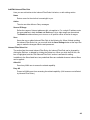
Add/Edit DHCP Reservation
This option lets you reserve IP addresses, and assign the same IP address to the network
device with the specified MAC address any time it requests an IP address. This is almost the
same as when a device has a static IP address except that the device must still request an IP
address from the router. The router will provide the device the same IP address every time.
DHCP Reservations are helpful for server computers on the local network that are hosting
applications such as Web and FTP. Servers on your network should either use a static IP
address or use this option.
Computer Name
You can assign a name for each computer that is given a reserved IP address. This may
help you keep track of which computers are assigned this way. Example: Game Server.
IP Address:
The LAN address that you want to reserve.
MAC Address
To input the MAC address of your system, enter it in manually or connect to the router's
Web-Management interface from the system and click the Copy Your PC’s MAC
Address button.
A MAC address is usually located on a sticker on the bottom of a network device. The
MAC address is comprised of twelve digits. Each pair of hexadecimal digits are usually
separated by dashes or colons such as 00-0D-88-11-22-33 or 00:0D:88:11:22:33. If your
network device is a computer and the network card is already located inside the computer,
you can connect to the router from the computer and click the Copy Your PC’s MAC
Address button to enter the MAC address.
As an alternative, you can locate a MAC address in a specific operating system by
following the steps below:
22
Windows 98
Windows Me
Windows 2000
Windows XP
Mac OS X
Go to the Start menu, select Run, type in winipcfg, and hit Enter. A
popup window will be displayed. Select the appropriate adapter from the
pull-down menu and you will see the Adapter Address. This is the MAC
address of the device.
Go to your Start menu, select Programs, select Accessories, and select
Command Prompt. At the command prompt type ipconfig /all and hit
Enter. The physical address displayed for the adapter connecting to the
router is the MAC address.
Go to the Apple Menu, select System Preferences, select Network, and
select the Ethernet Adapter connecting to the router. Select the Ethernet
button and the Ethernet ID will be listed. This is the same as the MAC
address.
DHCP Reservations List
This shows clients that you have specified to have reserved DHCP addresses. An entry can be
changed by clicking the Edit icon, or deleted by clicking the Delete icon. When you click the
Edit icon, the item is highlighted, and the "Edit DHCP Reservation" section is activated for
editing.
Number of Dynamic DHCP Clients
In this section you can see what LAN devices are currently leasing IP addresses.
Revoke
The Revoke option is available for the situation in which the lease table becomes full or
nearly full, you need to recover space in the table for new entries, and you know that
some of the currently allocated leases are no longer needed. Clicking Revoke cancels the
lease for a specific LAN device and frees an entry in the lease table. Do this only if the
device no longer needs the leased IP address, because, for example, it has been
removed from the network.
Reserve
The Reserve option converts this dynamic IP allocation into a DHCP Reservation and
adds the corresponding entry to the DHCP Reservations List.
23
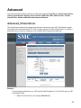
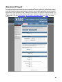
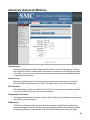
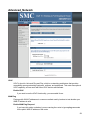
Advanced
The Advanced tab provides the following configuration options: Virtual Server, Special Applications,
Gaming, StreamEngine, Routing, Access Control, WEB Filter, MAC Address Filter, Firewall,
Inbound Filter, Advanced Wireless and Advanced Network.
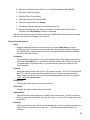
Advanced_Virtual Server
The Virtual Server option gives Internet users access to services on your LAN. This feature is useful
for hosting online services such as FTP, Web, or game servers. For each Virtual Server, you define a
public port on your router for redirection to an internal LAN IP Address and LAN port.
Example:
You are hosting a Web Server on a PC that has LAN IP Address of 192.168.2.50 and your ISP
is blocking Port 80.
1. Name the Virtual Server (for example: Web Server)
24
2. Enter the IP Address of the machine on your LAN (for example: 192.168.2.50
3. Enter the Private Port as [80]
4. Enter the Public Port as [8888]
5. Select the Protocol (for example TCP).
6. Ensure the schedule is set to Always
7. Click Save to add the settings to the Virtual Servers List
8. Repeat these steps for each Virtual Server Rule you wish to add. After the list is
complete, click Save Settings at the top of the page.
With this Virtual Server entry, all Internet traffic on Port 8888 will be redirected to your internal
web server on port 80 at IP Address 192.168.2.50.
Virtual Server Parameters
Name
Assign a meaningful name to the virtual server, for example Web Server. Several
well-known types of virtual server are available from the "Application Name" drop-down
list. Selecting one of these entries fills some of the remaining parameters with standard
values for that type of server.
IP Address
The IP address of the system on your internal network that will provide the virtual service,
for example 192.168.2.50. You can select a computer from the list of DHCP clients in the
"Computer Name" drop-down menu, or you can manually enter the IP address of the
server computer.
Protocol
Select the protocol used by the service. The common choices -- UDP, TCP, and both UDP
and TCP -- can be selected from the drop-down menu. To specify any other protocol,
select "Other" from the list, then enter the corresponding protocol number ( as assigned
by the IANA) in the Protocol box.
Private Port
The port that will be used on your internal network.
Public Port
The port that will be accessed from the Internet.
Inbound Filter
Select a filter that controls access as needed for this virtual server. If you do not see the
filter you need in the list of filters, go to the Advanced → Inbound Filter screen and create
a new filter.
Schedule
Select a schedule for when the service will be enabled. If you do not see the schedule you
need in the list of schedules, go to the Tools → Schedules screen and create a new
schedule.
25
Add/Edit Virtual Server
In this section you can add an entry to the Virtual Servers List below or edit an existing entry.
Enable
Entries in the list can be either active (enabled) or inactive (disabled).
Save
Saves the new or edited virtual server entry in the following list. When finished updating
the virtual server entries, you must still click the Save Settings button at the top of the
page to make the changes effective and permanent.
Virtual Servers List
The section shows the currently defined virtual servers. A Virtual Server can be changed by
clicking the Edit icon, or deleted by clicking the Delete icon. When you click the Edit icon, the
item is highlighted, and the "Edit Virtual Server" section is activated for editing.
You might have trouble accessing a virtual server using its public identity (WAN-side
IP-address of the gateway or its dynamic DNS name) from a machine on the LAN. Your
requests may not be looped back or you may be redirected to the "Forbidden" page.
This will happen if you have an Access Control Rule configured for this LAN machine.
The requests from the LAN machine will not be looped back if Internet access is blocked at the time of
access. To work around this problem, access the LAN machine using its LAN-side identity.
Requests may be redirected to the "Forbidden" page if web access for the LAN machine is restricted
by an Access Control Rule. Add the WAN-side identity (WAN-side IP-address of the router or its
dynamic DNS name) on the Advanced → Web Filter screen to work around this problem.
26
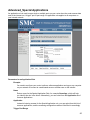
Advanced_Special Applications
An application rule is used to open single or multiple ports on your router when the router senses data
sent to the Internet on a "trigger" port or port range. An application rule applies to all computers on
your internal network.
Parameters for an Application Rule
Example:
You need to configure your router to allow a software application running on any computer
on your network to connect to a web-based server or another user on the Internet.
Name
Enter a name for the Special Application Rule, for example Game App, which will help
you identify the rule in the future. Alternatively, you can select from the Application list of
common applications.
Application
Instead of entering a name for the Special Application rule, you can select from this list of
common applications, and the remaining configuration values will be filled in accordingly.
Trigger Port Range
27
Enter the outgoing port range used by your application (for example 6500-6700).
Trigger Protocol
Select the outbound protocol used by your application (for example Both).
Input Port Range
Enter the port range that you want to open up to Internet traffic (for example 6000-6200).
Input Protocol
Select the protocol used by the Internet traffic coming back into the router through the
opened port range (for example Both).
Schedule
Select a schedule for when this rule is in effect. If you do not see the schedule you need
in the list of schedules, go to the Tools → Schedules screen and create a new schedule.
With the above example application rule enabled, the router will open up a range of ports from
6000-6200 for incoming traffic from the Internet, whenever any computer on the internal
network opens up an application that sends data to the Internet using a port in the range of
6500-6700.
Add/Edit Special Applications Rule
This section is where you define and edit Special Applications Rules.
Save
Saves the new or edited Special Applications Rule in the following list. When finished
updating the special applications rules, you must still click the Save Settings button at the
top of the page to make the changes effective and permanent.
Special Applications Rules List
The section shows the currently defined special applications rules. A special applications rule
can be changed by clicking the Edit icon, or deleted by clicking the Delete icon. When you click
the Edit icon, the item is highlighted, and the "Edit Special Applications Rule" section is
activated for editing.
28
Advanced_Gaming
Multiple connections are required by some applications, such as internet games, video conferencing,
Internet telephony, and others. These applications have difficulties working through NAT (Network
Address Translation). This section is used to open multiple ports or a range of ports in your router and
redirect data through those ports to a single PC on your network. You can enter ports in various
formats:
Range (50-100)
Individual (80, 68, 888)
Mixed (1020-5000, 689)
Example:
Suppose you are hosting an online game server that is running on a PC with a private IP
Address of 192.168.2.50. This game requires that you open multiple ports (6159-6180, 99) on
the router so Internet users can connect.
Port Forwarding Fields
Name
29
Give the rule a name that is meaningful to you, for example Game Server. You can also select
from a list of popular games, and many of the remaining configuration values will be filled in
accordingly. However, you should check whether the port values have changed since this list
was created, and you must fill in the IP address field.
IP Address
Enter the local network IP address of the system hosting the server, for example 192.168.2.50.
TCP Ports To Open
Enter the TCP ports to open (for example 6159-6180, 99).
UDP Ports To Open
Enter the UDP ports to open (for example 6159-6180, 99).
Inbound Filter
Select a filter that controls access as needed for this rule. If you do not see the filter you need
in the list of filters, go to the Advanced → Inbound Filter screen and create a new filter.
Schedule
Select a schedule for the times when this rule is in effect. If you do not see the schedule you
need in the list of schedules, go to the Tools → Schedules screen and create a new schedule.
With the above example values filled in and this Gaming Rule enabled, all TCP and UDP traffic
on ports 6159 through 6180 and port 99 is passed through the router and redirected to the
Internal Private IP Address of your Game Server at 192.168.2.50.
Edit/Add Game Rule
Here you can add entries to the Game Rules List below, or edit existing entries.
Enable
Each entry in Game Rules List can be active (enabled) or inactive (disabled)
Save
Saves the new or edited Game Rule in the following list. When finished updating the game
rules, you must still click the Save Settings button at the top of the page to make the changes
effective and permanent.
Game Rules List
The section shows the currently defined game rules. A game rule can be changed by clicking
the Edit icon, or deleted by clicking the Delete icon. When you click the Edit icon, the item is
highlighted, and the "Edit Game Rule" section is activated for editing.
30
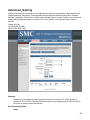
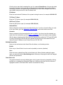
Advanced_StreamEngine
The StreamEngine feature helps improve your network gaming performance by prioritizing the data
flows of network applications.
StreamEngine Setup
Enable StreamEngine
Enable this option for better performance and experience with online games and other
interactive applications, such as VoIP.
31
Automatic Classification
This option is enabled by default so that your router will automatically determine which
programs should have network priority.
Dynamic Fragmentation
This option should be enabled when you have a slow Internet uplink. It helps to reduce
the impact that large low priority network packets can have on more urgent ones by
breaking the large packets into several smaller packets.
Automatic Uplink Speed
When enabled, this option causes the router to automatically measure the useful uplink
bandwidth each time the WAN interface is re-established (after a reboot, for example).
Measured Uplink Speed
This is the uplink speed measured when the WAN interface was last re-established. The
value may be lower than that reported by your ISP as it does not include all of the network
protocol overheads associated with your ISP's network. Typically, this figure will be
between 87% and 91% of the stated uplink speed for xDSL connections and around 5
kbps lower for cable network connections.
Manual Uplink Speed
If Automatic Uplink Speed is disabled, this options allows you to set the uplink speed
manually. Uplink speed is the speed at which data can be transferred from the router to
your ISP. This is determined by your ISP. ISPs often specify speed as a downlink/uplink
pair; for example, 1.5Mbps/284kbps. For this example, you would enter "284".
Alternatively you can test your uplink speed with a service such as www.dslreports.com.
Note however that sites such as DSL Reports, because they do not consider as many
network protocol overheads, will generally note speeds slightly lower than the Measured
Uplink Speed or the ISP rated speed.
Connection Type
By default, the router automatically determines whether the underlying connection is an
xDSL/Frame-relay network or some other connection type (such as cable modem or
Ethernet), and it displays the result as Detected xDSL or Frame Relay Network. If you
have an unusual network connection in which you are actually connected via xDSL but for
which you configure either "Static" or "DHCP" in the WAN settings, setting this option to
xDSL or Other Frame Relay Network ensures that the router will recognize that it needs
to shape traffic slightly differently in order to give the best performance. Choosing xDSL
or Other Frame Relay Network causes the measured uplink speed to be reported
slightly lower than before on such connections, but gives much better results.
Detected xDSL or Frame Relay Network
When Connection Type is set to Auto-detect, the automatically detected connection
type is displayed here.
StreamEngine Rules
A StreamEngine Rule identifies a specific message flow and assigns a priority to that flow. For
most applications, automatic classification will be adequate, and specific StreamEngine Rules
will not be required.
Conflicting rules are not permitted. Conflicting rules are those that share any combination of
source address/port, destination address/port, and protocol. Rejecting conflicting rules ensures
32
that every flow defined in a rule receives the expected priority and avoids indeterminate
prioritization that could reduce QoS effectiveness.
Name
Create a name for the rule that is meaningful to you.
Priority
The priority of the message flow is entered here -- 1 receives the highest priority (most
urgent) and 255 receives the lowest priority (least urgent). Priority 0 is reserved. Flows
that are not prioritized by any rule receive lowest priority.
Protocol
The protocol used by the messages. The common choices can be selected from the
drop-down menu. To specify any other protocol, enter its protocol number (as assigned by
the IANA) in the Protocol box.
Source IP Range
The rule applies to a flow of messages whose LAN-side IP address falls within the range
set here.
Source Port Range
The rule applies to a flow of messages whose LAN-side port number is within the range
set here.
Destination IP Range
The rule applies to a flow of messages whose WAN-side IP address falls within the range
set here.
Destination Port Range
The rule applies to a flow of messages whose WAN-side port number is within the range
set here.
Add/Edit StreamEngine Rule
Enable
Each entry in StreamEngine Rules List can be active (enabled) or inactive (disabled)
Save
Saves the new or edited StreamEngine Rule in the following list. When finished updating
the StreamEngine rules, you must still click the Save Settings button at the top of the
page to make the changes effective and permanent.
StreamEngine Rules List
The section shows the currently defined StreamEngine rules. A StreamEngine rule can be
changed by clicking the Edit icon, or deleted by clicking the Delete icon. When you click the
Edit icon, the item is highlighted, and the "Edit StreamEngine Rule" section is activated for
editing.
33
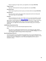
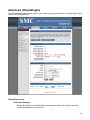
Advanced_Routing
Add/Edit Route
Adds a new route to the IP routing table or edits an existing route.
Enable: Specifies whether the entry will be enabled or disabled.
Destination IP: The IP address of packets that will take this route.
Netmask: One bits in the mask specify which bits of the IP address must match.
Gateway: Specifies the next hop to be taken if this route is used. A gateway of 0.0.0.0 implies
there is no next hop, and the IP address matched is directly connected to the router on the
interface specified: LAN or WAN.
Interface: Specifies the interface -- LAN or WAN -- that the IP packet must use to transit out of
the router, when this route is used.
Metric: The route metric is a value from 1 to 16 that indicates the cost of using this route. A
value of 1 is the lowest cost, and 15 is the highest cost. A value of 16 indicates that the route is
not reachable from this router. When trying to reach a particular destination, computers on your
network will select the best route, ignoring unreachable routes.
34
Save: Saves the new or edited route in the following list. When finished updating the routing
table, you must still click the Save Settings button at the top of the page to make the changes
effective and permanent.
Routes List
The section shows the current routing table entries. Certain required routes are predefined and
cannot be changed. Routes that you add can be changed by clicking the Edit icon, or deleted
by clicking the Delete icon. When you click the Edit icon, the item is highlighted, and the "Edit
Route" section is activated for editing.
35
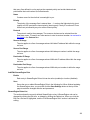
Advanced_Access Control
The Access Control section allows you to control access in and out of devices on your network. Use
this feature as Parental Controls to only grant access to approved sites, limit web access based on
time or dates, and/or block access from applications such as peer-to-peer utilities or games.
Enable
By default, the Access Control feature is disabled. If you need Access Control, check this
option.
When Access Control is disabled, every device on the LAN has unrestricted access
to the Internet. However, if you enable Access Control, Internet access is restricted
for those devices that have an Access Control Policy configured for them. All other
devices have unrestricted access to the Internet.
Policy Wizard
The Policy Wizard guides you through the steps of defining each access control policy. A
policy is the "Who, What, When, and How" of access control -- whose computer will be
affected by the control, what internet addresses are controlled, when will the control be in
effect, and how is the control implemented. You can define multiple policies. The Policy Wizard
starts when you click the button below and also when you edit an existing policy.
Add Policy
Click this button to start creating a new access control policy.
Policy Table
36
This section shows the currently defined access control policies. A policy can be changed by
clicking the Edit icon, or deleted by clicking the Delete icon. When you click the Edit icon, the
Policy Wizard starts and guides you through the process of changing a policy. You can enable
or disable specific policies in the list by clicking the "Enable" checkbox.
37
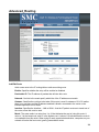
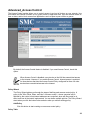
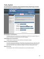
Advanced_WEB Filter
This section is where you add the Web sites to be used for Access Control. The Web sites listed here
are used when the Web Filter option is enabled in Access Control.
The Web Filter section is one of two means by which you can specify the web sites you want to allow.
You also have the alternative of using the Sentinel Parental Controls Service, which allows you to
specify broad categories of web sites and saves you the trouble of entering specific web site URLs.
For more information about the Sentinel service, refer to Tools → Sentinel.
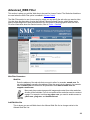
Web Filter Parameters
Web Site
Enter the address of the web site that you want to allow; for example: google.com. Do
not enter the http:// preceding the address. Enter the most inclusive domain; for example,
enter u-media.com and access will be permitted to both www.u-media.com and
support.u-media.com.
Many web sites construct pages with images and content from other web sites.
Access will be forbidden if you do not enable all the web sites used to construct
a page. For example, to access my.yahoo.com, you need to enable access to
yahoo.com, yimg.com, and doubleclick.net.
Add/Edit Web Site
This is where you can add Web sites to the Allowed Web Site List or change entries in the
Allowed Web Site List.
38
Enable
Entries in the Allowed Web Site List can be activated or deactivated with this checkbox.
New entries are activated by default.
Save
Saves the new or edited Allowed Web Site in the following list. When finished updating
the Allowed Web Site List, you must still click the Save Settings button at the top of the
page to make the changes effective and permanent.
Allowed Web Site List
The section lists the currently allowed web sites. An allowed web site can be changed by
clicking the Edit icon, or deleted by clicking the Delete icon. When you click the Edit icon, the
item is highlighted, and the "Edit Web Site" section is activated for editing.
39
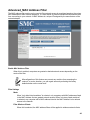
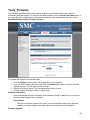
Advanced_MAC Address Filter
The MAC address filter section can be used to filter network access by machines based on the unique
MAC addresses of their network adapter(s). It is most useful to prevent unauthorized wireless devices
from connecting to your network. A MAC address is a unique ID assigned by the manufacturer of the
network adapter.
Enable MAC Address Filter
When this is enabled, computers are granted or denied network access depending on the
mode of the filter.
Misconfiguration of this feature can prevent any machine from accessing the
network. In such a situation, you can regain access by activating the factory
defaults button on the router itself.
Filter Settings
Mode
When "only allow listed machines" is selected, only computers with MAC addresses listed
in the MAC Address List are granted network access. When "only deny listed machines"
is selected, any computer with a MAC address listed in the MAC Address List is refused
access to the network.
Filter Wireless Clients
When this is selected, the MAC address filters will be applied to wireless network clients.
40
Filter Wired Clients
When this is selected, the MAC address filters will be applied to wired network clients.
Add/Edit MAC Address
In this section, you can add entries to the MAC Address List below, or edit existing entries.
Enable
MAC address entries can be activated or deactivated with this checkbox.
MAC Address
Enter the MAC address of the desired computer or connect to the router from the desired
computer and click the Copy Your PC’s MAC Address button.
Save
Saves the new or edited MAC Address entry in the following list. When finished updating the
MAC Address List, you must still click the Save Settings button at the top of the page to make
the changes effective and permanent.
MAC Address List
The section lists the current MAC Address filters. A MAC Address entry can be changed by
clicking the Edit icon, or deleted by clicking the Delete icon. When you click the Edit icon, the
item is highlighted, and the "Edit MAC Address" section is activated for editing.
41
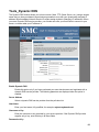
Advanced_Firewall
The router provides a tight firewall by virtue of the way NAT works. Unless you configure the router to
the contrary, the NAT does not respond to unsolicited incoming requests on any port, thereby making
your LAN invisible to Internet cyber attackers. However, some network applications cannot run with a
tight firewall. Those applications need to selectively open ports in the firewall to function correctly. The
options on this page control several ways of opening the firewall to address the needs of specific types
of applications. See also Virtual Server, Port Forwarding, Application Rules, and UPnP for related
options.
42
Firewall Settings
Enable SPI
SPI ("stateful packet inspection" also known as "dynamic packet filtering") helps to
prevent cyber attacks by tracking more state per session. It validates that the traffic
passing through that session conforms to the protocol. When the protocol is TCP, SPI
checks that packet sequence numbers are within the valid range for the session,
discarding those packets that do not have valid sequence numbers.
Whether SPI is enabled or not, the router always tracks TCP connection states and
ensures that each TCP packet's flags are valid for the current state.
NAT Endpoint Filtering
The NAT Endpoint Filtering options control how the router's NAT manages incoming
connection requests to ports that are already being used.
Endpoint Independent
Once a LAN-side application has created a connection through a specific port, the NAT
will forward any incoming connection requests with the same port to the LAN-side
application regardless of their origin. This is the least restrictive option, giving the best
connectivity and allowing some applications (P2P applications in particular) to behave
almost as if they are directly connected to the Internet.
Address Restricted
The NAT forwards incoming connection requests to a LAN-side host only when they come
from the same IP address with which a connection was established. This allows the
remote application to send data back through a port different from the one used when the
outgoing session was created.
Port And Address Restricted
The NAT does not forward any incoming connection requests with the same port address
as an already establish connection.
Note that some of these options can interact with other port restrictions. Endpoint Independent
Filtering takes priority over inbound filters or schedules, so it is possible for an incoming
session request related to an outgoing session to enter through a port in spite of an active
inbound filter on that port. However, packets will be rejected as expected when sent to blocked
ports (whether blocked by schedule or by inbound filter) for which there are no active sessions.
Port and Address Restricted Filtering ensures that inbound filters and schedules work precisely,
but prevents some level of connectivity, and therefore might require the use of port triggers,
virtual servers, or port forwarding to open the ports needed by the application. Address
Restricted Filtering gives a compromise position, which avoids problems when communicating
with certain other types of NAT router (symmetric NATs in particular) but leaves inbound filters
and scheduled access working as expected.
UDP Endpoint Filtering
Controls endpoint filtering for packets of the UDP protocol.
TCP Endpoint Filtering
Controls endpoint filtering for packets of the TCP protocol.
DMZ Host
43
DMZ means "Demilitarized Zone." If an application has trouble working from behind the router,
you can expose one computer to the Internet and run the application on that computer.
When a LAN host is configured as a DMZ host, it becomes the destination for all incoming
packets that do not match some other incoming session or rule. If any other ingress rule is in
place, that will be used instead of sending packets to the DMZ host; so, an active session,
virtual server, active port trigger, or port forwarding rule will take priority over sending a packet
to the DMZ host. (The DMZ policy resembles a default port forwarding rule that forwards every
port that is not specifically sent anywhere else.)
The router provides only limited firewall protection for the DMZ host. The router does not
forward a TCP packet that does not match an active DMZ session, unless it is a connection
establishment packet (SYN). Except for this limited protection, the DMZ host is effectively
"outside the firewall". Anyone considering using a DMZ host should also consider running a
firewall on that DMZ host system to provide additional protection.
Packets received by the DMZ host have their IP addresses translated from the WAN-side IP
address of the router to the LAN-side IP address of the DMZ host. However, port numbers are
not translated; so applications on the DMZ host can depend on specific port numbers.
The DMZ capability is just one of several means for allowing incoming requests that might
appear unsolicited to the NAT. In general, the DMZ host should be used only if there are no
other alternatives, because it is much more exposed to cyber attacks than any other system on
the LAN. Thought should be given to using other configurations instead: a virtual server, a port
forwarding rule, or a port trigger. Virtual servers open one port for incoming sessions bound for
a specific application (and also allow port redirection and the use of ALGs). Port forwarding is
rather like a selective DMZ, where incoming traffic targeted at one or more ports is forwarded
to a specific LAN host (thereby not exposing as many ports as a DMZ host). Port triggering is a
special form of port forwarding, which is activated by outgoing traffic, and for which ports are
only forwarded while the trigger is active.
Few applications truly require the use of the DMZ host. Following are examples of when a
DMZ host might be required:
•
A host needs to support several applications that might use overlapping ingress ports
such that two port forwarding rules cannot be used because they would potentially be in
conflict.
•
To handle incoming connections that use a protocol other than ICMP, TCP, UDP, and
IGMP (also GRE and ESP, when these protocols are enabled by the PPTP and IPSec
ALGs ).
Enable DMZ
Putting a computer in the DMZ may expose that computer to a variety of
security risks. Use of this option is only recommended as a last resort.
DMZ IP Address
Specify the LAN IP address of the LAN computer that you want to have unrestricted
Internet communication. If this computer obtains its address Automatically using DHCP,
then you may want to make a static reservation on the Basic → Network Settings page so
that the IP address of the DMZ computer does not change.
44
Non-UDP/TCP/ICMP LAN Sessions
When a LAN application that uses a protocol other than UDP, TCP, or ICMP initiates a session
to the Internet, the router's NAT can track such a session, even though it does not recognize
the protocol. This feature is useful because it enables certain applications (most importantly a
single VPN connection to a remote host) without the need for an ALG.
Note that this feature does not apply to the DMZ host (if one is enabled). The DMZ host always
handles these kinds of sessions.
Enable
Enabling this option (the default setting) enables single VPN connections to a remote host.
(But, for multiple VPN connections, the appropriate VPN ALG must be used.) Disabling
this option, however, only disables VPN if the appropriate VPN ALG is also disabled.
Application Level Gateway (ALG) Configuration
Here you can enable or disable ALGs. Some protocols and applications require special
handling of the IP payload to make them work with network address translation (NAT). Each
ALG provides special handling for a specific protocol or application. A number of ALGs for
common applications are enabled by default.
PPTP
Allows multiple machines on the LAN to connect to their corporate networks using PPTP
protocol. When the PPTP ALG is enabled, LAN computers can establish PPTP VPN
connections either with the same or with different VPN servers. When the PPTP ALG is
disabled, the router allows VPN operation in a restricted way -- LAN computers are
typically able to establish VPN tunnels to different VPN Internet servers but not to the
same server. The advantage of disabling the PPTP ALG is to increase VPN performance.
Enabling the PPTP ALG also allows incoming VPN connections to a LAN side VPN server
(refer to Virtual Server).
IPSec (VPN)
Allows multiple VPN clients to connect to their corporate networks using IPSec. Some
VPN clients support traversal of IPSec through NAT. This option may interfere with the
operation of such VPN clients. If you are having trouble connecting with your corporate
network, try disabling this option.
Check with the system administrator of your corporate network whether your VPN client
supports NAT traversal.
Note that L2TP VPN connections typically use IPSec to secure the connection. To achieve
multiple VPN pass-through in this case, the IPSec ALG must be enabled.
RTSP
Allows applications that use Real Time Streaming Protocol to receive streaming media
from the internet. QuickTime and Real Player are some of the common applications using
this protocol.
Windows/MSN Messenger
Supports use on LAN computers of Microsoft Windows Messenger (the Internet
messaging client that ships with Microsoft Windows) and MSN Messenger. The SIP ALG
must also be enabled when the Windows Messenger ALG is enabled.
FTP
45
Allows FTP clients and servers to transfer data across NAT. Refer to the
Advanced → Virtual Server page if you want to host an FTP server.
H.323 (Netmeeting)
Allows H.323 (specifically Microsoft Netmeeting) clients to communicate across NAT. Note
that if you want your buddies to call you, you should also set up a virtual server for
NetMeeting. Refer to the Advanced → Virtual Server page for information on how to set
up a virtual server.
SIP
Allows devices and applications using VoIP (Voice over IP) to communicate across NAT.
Some VoIP applications and devices have the ability to discover NAT devices and work
around them. This ALG may interfere with the operation of such devices. If you are having
trouble making VoIP calls, try turning this ALG off.
Wake-On-LAN
This feature enables forwarding of "magic packets" (that is, specially formatted wake-up
packets) from the WAN to a LAN computer or other device that is "Wake on LAN" (WOL)
capable. The WOL device must be defined as such on the Advanced → Virtual Server
page. The LAN IP address for the virtual server is typically set to the broadcast address
192.168.2.255. The computer on the LAN whose MAC address is contained in the magic
packet will be awakened.
MMS
Allows Windows Media Player, using MMS protocol, to receive streaming media from the
internet.
46
Advanced_Inbound Filter
When you use the Virtual Server, Gaming, or Remote Administration features to open specific ports to
traffic from the Internet, you could be increasing the exposure of your LAN to cyber attacks from the
Internet. In these cases, you can use Inbound Filters to limit that exposure by specifying the IP
addresses of internet hosts that you trust to access your LAN through the ports that you have opened.
You might, for example, only allow access to a game server on your home LAN from the computers of
friends whom you have invited to play the games on that server.
Inbound Filters can be used for limiting access to a server on your network to a system or group of
systems. Filter rules can be used with Virtual Server, Gaming, or Remote Administration features.
Each filter can be used for several functions; for example a "Game Clan" filter might allow all of the
members of a particular gaming group to play several different games for which gaming entries have
been created. At the same time an "Admin" filter might only allows systems from your office network to
access the WAN admin pages and an FTP server you use at home. If you add an IP address to a filter,
the change is effected in all of the places where the filter is used.
47
Add/Edit Inbound Filter Rule
Here you can add entries to the Inbound Filter Rules List below, or edit existing entries.
Name
Enter a name for the rule that is meaningful to you.
Action
The rule can either Allow or Deny messages.
Source IP Range
Define the ranges of Internet addresses this rule applies to. For a single IP address, enter
the same address in both the Start and End boxes. Up to eight ranges can be entered.
The Enable checkbox allows you to turn on or off specific entries in the list of ranges.
Save
Saves the new or edited Inbound Filter Rule in the following list. When finished updating
the Inbound Filter Rules List, you must still click the Save Settings button at the top of the
page to make the changes effective and permanent.
Inbound Filter Rules List
The section lists the current Inbound Filter Rules. An Inbound Filter Rule can be changed by
clicking the Edit icon, or deleted by clicking the Delete icon. When you click the Edit icon, the
item is highlighted, and the "Edit Inbound Filter Rule" section is activated for editing.
In addition to the filters listed here, two predefined filters are available wherever inbound filters
can be applied:
Allow All
Permit any WAN user to access the related capability.
Deny All
Prevent all WAN users from accessing the related capability. (LAN users are not affected
by Inbound Filter Rules.)
48
Advanced_Advanced Wireless
Transmit Power
Normally the wireless transmitter operates at 100% power. In some circumstances, however,
there might be a need to isolate specific frequencies to a smaller area. By reducing the power
of the radio, you can prevent transmissions from reaching beyond your corporate/home office
or designated wireless area.
Beacon Period
Beacons are packets sent by a wireless router to synchronize wireless devices. Specify a
Beacon Period value between 20 and 1000. The default value is set to 100 milliseconds.
RTS Threshold
This setting should remain at its default value of 2346. If you encounter inconsistent data flow,
only minor modifications to the value are recommended.
Fragmentation Threshold
This setting should remain at its default value of 2346. Setting the Fragmentation value too low
may result in poor performance.
DTIM Interval
A DTIM is a countdown informing clients of the next window for listening to broadcast and
multicast messages. When the wireless router has buffered broadcast or multicast messages
for associated clients, it sends the next DTIM with a DTIM Interval value. Wireless clients
49
detect the beacons and awaken to receive the broadcast and multicast messages. The default
value is 1. Valid settings are between 1 and 255.
802.11d Enable
Enables 802.11d operation. 802.11d is a wireless specification for operation in additional
regulatory domains. This supplement to the 802.11 specifications defines the physical layer
requirements (channelization, hopping patterns, new values for current MIB attributes, and
other requirements to extend the operation of 802.11 WLANs to new regulatory domains
(countries). The current 802.11 standard defines operation in only a few regulatory domains
(countries). This supplement adds the requirements and definitions necessary to allow 802.11
WLAN equipment to operate in markets not served by the current standard. Enable this option
if you are operating in one of these "additional regulatory domains".
WMM Enable
Enabling WMM can help control latency and jitter when transmitting multimedia content over a
wireless connection.
Short GI
Using a short (400ns) guard interval can increase throughput. However, it can also increase
error rate in some installations, due to increased sensitivity to radio-frequency reflections.
Select the option that works best for your installation.
Extra Wireless Protection
Extra protection for neighboring 11b wireless networks. Turn this option off to reduce the
adverse effect of legacy wireless networks on 802.11ng performance.
WDS Enable
When WDS is enabled, this access point functions as a wireless repeater and is able to
wirelessly communicate with other APs via WDS links. Note that WDS is incompatible with
WPA -- both features cannot be used at the same time. A WDS link is bidirectional; so this AP
must know the MAC Address (creates the WDS link) of the other AP, and the other AP must
have a WDS link back to this AP. Make sure the APs are configured with same channel
number.
WDS AP MAC Address
Specifies one-half of the WDS link. The other AP must also have the MAC address of this AP
to create the WDS link back to this AP. Enter a MAC address for each of the other APs that
you want to connect with WDS.
50
Advanced_Network
UPnP
UPnP is short for Universal Plug and Play, which is a networking architecture that provides
compatibility among networking equipment, software, and peripherals. This router has optional
UPnP capability, and can work with other UPnP devices and software.
Enable UPnP
If you need to use the UPnP functionality, you can enable it here.
WAN Ping
Pinging public WAN IP addresses is a common method used by hackers to test whether your
WAN IP address is valid.
Enable WAN Ping Respond
If you leave this option unchecked, you are causing the router to ignore ping commands
for the public WAN IP address of the router.
51
WAN Port Speed
Normally, this is set to "auto". If you have trouble connecting to the WAN, try the other settings.
Multicast Streams
The router uses the IGMP protocol to support efficient multicasting -- transmission of identical
content, such as multimedia, from a source to a number of recipients.
Enable Multicast Streams
This option must be enabled if any applications on the LAN participate in a multicast
group. If you have a multimedia LAN application that is not receiving content as expected,
try enabling this option.
52
Tools
The Tools tab provides the following configuration options: Admin, Time, Syslog, Email Settings,
System, Firmware, Dynamic DNS, Windows Connect Now, System Check & Schedules.
Tools_Admin
The Admin option is used to set a password for access to the Web-based management. By default
there is no password configured. It is highly recommended that you create a password to keep your
new router secure.
Admin Password
Enter a password for the user "admin", who will have full access to the Web-based
53
management interface.
User Password
Enter a password for the user "user", who will have read-only access to the Web-based
management interface.
Gateway Name
The name of the router can be changed here.
Enable Remote Management
Enabling Remote Management allows you to manage the router from anywhere on the Internet.
Disabling Remote Management allows you to manage the router only from computers on your
LAN.
Remote Admin Port
The port that you will use to address the management interface from the Internet. For example,
if you specify port 1080 here, then, to access the router from the Internet, you would use a URL
of the form: http://my.domain.com:1080/.
Remote Admin Inbound Filter
Select a filter that controls access as needed for this admin port. If you do not see the filter you
need in the list of filters, go to the Advanced → Inbound Filter screen and create a new filter.
54
Tools_Time
The Time Configuration option allows you to configure, update, and maintain the correct time on the
router's internal system clock. From this section you can set the time zone that you are in and set the
Time Server. Daylight saving can also be configured to automatically adjust the time when needed.
55
Time Configuration
Current Router Time
Displays the time currently maintained by the router. If this is not correct, use the following
options to configure the time correctly.
Time Zone
Select your local time zone from pull down menu.
Enable Daylight Saving
Check this option if your location observes daylight saving time.
Daylight Saving Offset
Select the time offset, if your location observes daylight saving time.
DST Start and DST End
Select the starting and ending times for the change to and from daylight saving time. For
example, suppose for DST Start you select Month="Oct", Week="3rd", Day="Sun" and
Time="2am". This is the same as saying: "Daylight saving starts on the third Sunday of
October at 2:00 AM."
Automatic Time Configuration
Enable NTP Server
Select this option if you want to synchronize the router's clock to a Network Time Server
over the Internet. If you are using schedules or logs, this is the best way to ensure that the
schedules and logs are kept accurate.
NTP Server Used
Select a Network Time Server for synchronization. You can type in the address of a time
server or select one from the list. If you have trouble using one server, select another.
Set the Date and Time Manually
If you do not have the NTP Server option in effect, you can either manually set the time for
your router here, or you can click the Copy Your Computer’s Time Settings button to copy
the time from the computer you are using. (Make sure that computer's time is set correctly.)
If the router loses power for any reason, it cannot keep its clock running, and will not have
the correct time when it is started again. To maintain correct time for schedules and logs,
either you must enter the correct time after you restart the router, or you must enable the
NTP Server option.
56
Tools_Syslog
This section allows you to archive your log files to a Syslog Server.
Enable Logging to Syslog Server
Enable this option if you have a syslog server currently running on the LAN and wish to send
log messages to it.
Syslog Server IP Address
Enter the LAN IP address of the Syslog Server.
57
Tools_Email Settings
The Email feature can be used to send the system log files, router alert messages, and firmware
update notification to your email address.
Enable
Enable Email Notification
When this option is enabled, router activity logs or firmware upgrade notifications can be
emailed to a designated email address, and the following parameters are displayed.
Email Settings
From Email Address
This email address will appear as the sender when you receive a log file or firmware
upgrade notification via email.
To Email Address
Enter the email address where you want the email sent.
SMTP Server Address
Enter the SMTP server address for sending email.
Enable Authentication
If your SMTP server requires authentication, select this option.
Account Name
Enter your account for sending email.
58
Password
Enter the password associated with the account.
Verify Password
Re-type the password associated with the account.
Email Log When Full or on Schedule
On Log Full
Select this option if you want logs to be sent by email when the log is full.
On Schedule
Select this option if you want logs to be sent by email according to a schedule.
Schedule
If you selected the On Schedule option, select one of the defined schedule rules. If you do
not see the schedule you need in the list of schedules, go to the Tools -> Schedules
screen and create a new schedule.
Normally email is sent at the start time defined for a schedule, and the
schedule end time is not used. However, rebooting the router during the
schedule period will cause additional emails to be sent.
59
Tools_System
This section allows you to manage the router's configuration settings, reboot the router, and restore
the router to the factory default settings. Restoring the unit to the factory default settings will erase all
settings, including any rules that you've created.
Save Settings To Local Hard Drive
This option allows you to save the router's configuration to a file on your computer. Be sure to
save the configuration before performing a firmware upgrade.
Load Settings From Local Hard Drive
Use this option to restore previously saved router configuration settings.
Restore To Factory Default Settings
This option restores all configuration settings back to the settings that were in effect at the time
the router was shipped from the factory. Any settings that have not been saved will be lost. If
you want to save your router configuration settings, use the Save Settings option above.
Reboot The Device
This restarts the router. Useful for restarting when you are not near the device.
60
Tools_Firmware
The Firmware Upgrade section can be used to update to the latest firmware code to improve
functionality and performance. To check for the latest firmware, click the Check Online Now button. If
you would like to be notified when new firmware is released, place a checkmark in the box next to
Email Notification of Newer Firmware Version.
To upgrade the firmware, follow these steps:
1. Click the Browse button to locate the upgrade file on your computer.
2. Once you have found the file to be used, click the Upload button below to start the firmware
upgrade process. This can take a minute or more.
3. Wait for the router to reboot. This can take another minute or more.
4. Confirm updated firmware revision on status page.
Firmware Information
Here are displayed the version numbers of the firmware currently installed in your router and
the most recent upgrade that is available.
Check Online
This option will check support site to see if you have the latest version of the firmware
available. If a newer version is available, download instructions will be displayed.
Firmware Upgrade
61
Firmware upgrade cannot be performed from a wireless device. To perform an
upgrade, ensure that you are using a PC that is connected to the router by wire.
Some firmware upgrades reset the configuration options to the factory defaults.
Before performing an upgrade, be sure to save the current configuration from
the Tools -> Admin screen.
Upload
Once you have a firmware update on your computer, use this option to browse for the file
and then upload the information into the router.
62
Tools_Dynamic DNS
The Dynamic DNS feature allows you to host a server (Web, FTP, Game Server, etc.) using a domain
name that you have purchased (www.whateveryournameis.com) with your dynamically assigned IP
address. Most broadband Internet Service Providers assign dynamic (changing) IP addresses. When
you use a Dynamic DNS service provider, your friends can enter your host name to connect to your
server, no matter what your IP address is.
Enable Dynamic DNS
Enable this option only if you have purchased your own domain name and registered with a
dynamic DNS service provider. The following paramters are displayed when the option is
enabled.
Server Address
Select a dynamic DNS service provider from the pull-down list.
Host Name
Enter your host name, fully qualified; for example: myhost.mydomain.net.
Username or Key
Enter the username or key provided by your service provider. If the Dynamic DNS provider
supplies only a key, enter that key in all three fields.
Password or Key
63
Enter the password or key provided by your service provider. If the Dynamic DNS provider
supplies only a key, enter that key in all three fields.
Verify Password or Key
Re-type the password or key provided by your service provider. If the Dynamic DNS provider
supplies only a key, enter that key in all three fields.
Timeout
The time between periodic updates to the Dynamic DNS, if your dynamic IP address has not
changed. The timeout period is entered in hours.
If a dynamic DNS update fails for any reason (for example, when incorrect parameters are
entered), the router automatically disables the Dynamic DNS feature and records the
failure in the log.
After configuring the router for dynamic DNS, you can open a browser and navigate to the
URL for your domain (for example http://www.mydomain.info) and the router will attempt
to forward the request to port 80 on your LAN. If, however, you do this from a LAN-side
computer and there is no virtual server defined for port 80, the router will return the
router's configuration home page. Refer to the Advanced -> Virtual Server configuration
page to set up a virtual server.
64
Tools_System Check
Ping Test
"Ping" is an Internet utility function that sends a series of short messages to a target computer
and reports the results. You can use it to test whether a computer is running, and to get an
idea of the quality of the connection to that computer, based on the speed of the responses.
Host Name or IP Address
Enter either the IP address of the target computer or enter its fully qualified domain name.
Ping
Start pinging the specified host.
Stop
The host is pinged repeatedly until you press this button.
Example:
Host Name or IP Address
www.whitehouse.gov
Ping Result
Please wait, resolving www.whitehouse.gov....
Resolved to 205.161.7.102.
Response from 205.161.7.102 received in 7 milliseconds.
Response from 205.161.7.102 received in 6 milliseconds.
Response from 205.161.7.102 received in 7 milliseconds.
User stopped ping.
65
Tools_Schedules
Schedules can be created for use with enforcing rules. For example, if you want to restrict web access
to Mon-Fri from 3pm to 8pm, you could create a schedule selecting Mon, Tue, Wed, Thu, and Fri and
enter a Start Time of 3pm and End Time of 8pm.
Add/Edit Schedule Rule
In this section you can add entries to the Schedule Rules List below or edit existing entries.
Name
Give the schedule a name that is meaningful to you, such as "Weekday rule".
Day(s)
Place a checkmark in the boxes for the desired days or select the All Week radio button to
select all seven days of the week.
All Day - 24 hrs
Select this option if you want this schedule in effect all day for the selected day(s).
Start Time
If you don't use the All Day option, then you enter the time here. The start time is entered
in two fields. The first box is for the hour and the second box is for the minute. Email
events are normally triggered only by the start time.
End Time
66
The end time is entered in the same format as the start time. The hour in the first box and
the minutes in the second box. The end time is used for most other rules, but is not
normally used for email events.
Save
Saves the new or edited Schedule Rule in the following list. When finished updating the
Schedule Rules, you must still click the Save Settings button at the top of the page to
make the changes effective and permanent.
Schedule Rules List
This section shows the currently defined Schedule Rules. A Schedule Rule can be changed by
clicking the Edit icon, or deleted by clicking the Delete icon. When you click the Edit icon, the
item is highlighted, and the "Edit Schedule Rule" section is activated for editing.
67
Status
The Status tab provides the following configuration options: Device Info, Wireless, Routing, Logs,
Statistics and Active Sessions.
Status_Device info
All of your Internet and network connection details are displayed on the Device Info page. The
firmware version is also displayed here.
Some browsers have limitations that make it impossible to update the WAN status display
when the status changes. Some browsers require that you refresh the display to obtain
updated status. Some browsers report an error condition when trying to obtain WAN status.
68
69
Depending on the type of WAN connection, you can take one of the following sets of actions:
DHCP Connection
Clicking the DHCP Release button unassigns the router's IP address. The router will not
respond to IP messages from the WAN side until you click the DHCP Renew button or
power-up the router again. Clicking the DHCP Renew button causes the router to request a
new IP address from the ISP's server.
PPPoE, PPTP, L2TP Connection
Depending on whether the WAN connection is currently established, you can click either the
Connect to attempt to establish the WAN connection or the Disconnect to break the WAN
connection.
BigPond Connection
Depending on whether you are currently logged in to BigPond, you can click either the
BigPond Login to attempt to establish the WAN connection or the BigPond Logout to break
the WAN connection.
LAN Computers
This area of the screen continually updates to show all DHCP enabled computers and devices
connected to the LAN side of your router. The detection "range" is limited to the address range
as configured in DHCP Server. Computers that have an address outside of this range will not
show. If the DHCP Client (i.e. a computer configured to "Automatically obtain an address")
supplies a Host Name then that will also be shown. Any computer or device that has a static IP
address that lies within the detection "range" may show, however its host name will not.
IGMP Multicast memberships
If IGMP is enabled, this area of the screen show all multicast groups of which any LAN devices
are members.
70
Status_Wireless
The wireless section allows you to view the wireless clients that are connected to your wireless router.
MAC Address
The Ethernet ID (MAC address) of the wireless client.
IP Address
The LAN-side IP address of the client.
Mode
The transmission standard being used by the client. Values are 11a, 11b, or 11g for 802.11a,
802.11b, or 802.11g respectively.
Rate
The actual transmission rate of the client in megabits per second.
Signal
This is a relative measure of signal quality. The value is expressed as a percentage of
theoretical best quality. Signal quality can be reduced by distance, by interference from other
radio-frequency sources (such as cordless telephones or neighboring wireless networks), and
by obstacles between the router and the wireless device.
71
Status_Routing
The routing section displays all of the routing details configured for your router.
A value of 0.0.0.0 for gateway means there is no next hop, and the IP address is directly connected to
the router on the interface specified: LAN or WAN. A value of 0.0.0.0 in both the destination IP and
netmask means that this is the default route.
72
Status_Logs
The router automatically logs (records) events of possible interest in its internal memory. If there is not
enough internal memory for all events, logs of older events are deleted, but logs of the latest events
are retained. The Logs option allows you to view the router logs. You can define what types of events
you want to view and the level of events to view. This router also has external Syslog Server support
so you can send the log files to a computer on your network that is running a Syslog utility.
What to View
Select the kinds of events that you want to view.
•
Firewall and Security
•
System
•
Router Status
View Levels
Select the level of events that you want to view.
•
Critical
•
Warning
•
Informational
Apply Log Settings Now
73
Click this button after changing Log Options to make them effective and permanent.
Refresh
Clicking this button refreshes the display of log entries. There may be new events since the last
time you accessed the log.
Clear
Clicking this button erases all log entries.
Email Now
If you provided email information with the Tools -> Email screen, clicking the Email Now button
sends the router log to the configured email address.
Save Log
Select this option to save the router log to a file on you computer.
74
Status_Statistics
The Statistics page displays all of the LAN, WAN, and Wireless packet transmit and receive statistics.
Sent
The number of packets sent from the router.
Received
The number of packets received by the router.
TX Packets Dropped
The number of packets that were dropped while being sent, due to errors, collisions, or router
resource limitations.
RX Packets Dropped
The number of packets that were dropped while being received, due to errors, collisions, or
router resource limitations.
Collisions
The number of packets that were dropped due to Ethernet collisions (two or more devices
attempting to use an Ethernet circuit at the same time).
75
Errors
The number of transmission failures that cause loss of a packet. A noisy radio-frequency
environment can cause a high error rate on the wireless LAN.
76
Status_Active Sessions
The Active Sessions page displays full details of active sessions through your router. A session is a
conversation between a progam or application on a LAN-side computer and a program or application
on a WAN-side computer.
Internal
The IP address and port number of the LAN-side application.
Protocol
The communications protocol used for the conversation.
External
The IP address and port number of the WAN-side application.
NAT
The port number of the LAN-side application as viewed by the WAN-side application.
Priority
The preference given to outbound packets of this conversation by the StreamEngine logic.
Smaller numbers represent higher priority.
State
State for sessions that use the TCP protocol.
•
NO: None -- This entry is used as a placeholder for a future connection that may occur.
77
•
SS: SYN Sent -- One of the systems is attempting to start a connection.
•
EST: Established -- the connection is passing data.
•
FW: FIN Wait -- The client system has requested that the connection be stopped.
•
CW: Close Wait -- the server system has requested that the connection be stopped.
•
TW: Time Wait -- Waiting for a short time while a connection that was in FIN Wait is
fully closed.
•
LA: Last ACK -- Waiting for a short time while a connection that was in Close Wait is
fully closed.
•
CL: Closed -- The connection is no longer active but the session is being tracked in
case there are any retransmitted packets still pending.
Dir
The direction of initiation of the conversation:
Out
Initiated from LAN to WAN.
In
Initiated from WAN to LAN.
Time Out
The number of seconds of idle time until the router considers the session terminated. The initial
value of Time Out depends on the type and state of the connection.
300 seconds
UDP connections.
20 seconds
Reset or closed TCP connections. The connection does not close instantly so that
lingering packets can pass or the connection can be re-established.
120 seconds
Opening or closing TCP connections.
7800 seconds
Established TCP connections.
78
Glossary
A
Access Control List
ACL. This is a database of network devices that are allowed to access resources on the
network.
Access Point
AP. Device that allows wireless clients to connect to it and access the network
ActiveX
A Microsoft specification for the interaction of software components.
Ad-hoc network
Peer-to-Peer network between wireless clients
Address Resolution Protocol
ARP. Used to map MAC addresses to IP addresses so that conversions can be made in both
directions.
ADSL
Asymmetric Digital Subscriber Line
Advanced Encryption Standard
AES. Government encryption standard
Alphanumeric
Characters A-Z and 0-9
Antenna
Used to transmit and receive RF signals.
AppleTalk
A set of Local Area Network protocols developed by Apple for their computer systems
AppleTalk Address Resolution Protocol
AARP. Used to map the MAC addresses of Apple computers to their AppleTalk network
addresses, so that conversions can be made in both directions.
Application layer
7th Layer of the OSI model. Provides services to applications to ensure that they can
communicate properly with other applications on a network.
ASCII
79
American Standard Code for Information Interchange. This system of characters is most
commonly used for text files
Attenuation
The loss in strength of digital and analog signals. The loss is greater when the signal is being
transmitted over long distances.
Authentication
To provide credentials, like a Password, in order to verify that the person or device is really
who they are claiming to be
Automatic Private IP Addressing
APIPA. An IP address that that a Windows computer will assign itself when it is configured to
obtain an IP address automatically but no DHCP server is available on the network
B
Backward Compatible
The ability for new devices to communicate and interact with older legacy devices to guarantee
interoperability
Bandwidth
The maximum amount of bytes or bits per second that can be transmitted to and from a
network device
Basic Input/Output System
BIOS. A program that the processor of a computer uses to startup the system once it is turned
on
Baud
Data transmission speed
Beacon
A data frame by which one of the stations in a Wi-Fi network periodically broadcasts network
control data to other wireless stations.
Bit rate
The amount of bits that pass in given amount of time
Bit/sec
Bits per second
BOOTP
Bootstrap Protocol. Allows for computers to be booted up and given an IP address with no user
intervention
Bottleneck
80
A time during processes when something causes the process to slowdown or stop all together
Broadband
A wide band of frequencies available for transmitting data
Broadcast
Transmitting data in all directions at once
Browser
A program that allows you to access resources on the web and provides them to you
graphically
C
Cable modem
A device that allows you to connect a computer up to a coaxial cable and receive Internet
access from your Cable provider
CardBus
A newer version of the PC Card or PCMCIA interface. It supports a 32-bit data path, DMA, and
consumes less voltage
CAT 5
Category 5. Used for 10/100 Mbps or 1Gbps Ethernet connections
Client
A program or user that requests data from a server
Collision
When do two devices on the same Ethernet network try and transmit data at the exact same
time.
Cookie
Information that is stored on the hard drive of your computer that holds your preferences to the
site that gave your computer the cookie
D
Data
Information that has been translated into binary so that it can be processed or moved to
another device
Data Encryption Standard
Uses a randomly selected 56-bit key that must be known by both the sender and the receiver
when information is exchanged
Data-Link layer
81
The second layer of the OSI model. Controls the movement of data on the physical link of a
network
Database
Organizes information so that it can be managed updated, as well as easily accessed by users
or applications.
DB-25
A 25 ping male connector for attaching External modems or RS-232 serial devices
DB-9
A 9 pin connector for RS-232 connections
dBd
Decibels related to dipole antenna
dBi
Decibels relative to isotropic radiator
dBm
Decibels relative to one milliwatt
Decrypt
To unscramble an encrypted message back into plain text
Default
A predetermined value or setting that is used by a program when no user input has been
entered for this value or setting
Demilitarized zone
DMZ: A single computer or group of computers that can be accessed by both users on the
Internet as well as users on the Local Network, but that is not protected by the same security
as the Local Network.
DHCP
Dynamic Host Configuration Protocol: Used to automatically assign IP addresses from a
predefined pool of addresses to computers or devices that request them
Digital certificate:
An electronic method of providing credentials to a server in order to have access to it or a
network
Direct Sequence Spread Spectrum
DSSS: Modulation technique used by 802.11b wireless devices
DMZ
82
"Demilitarized Zone". A computer that logically sits in a "no-mans land" between the LAN and
the WAN. The DMZ computer trades some of the protection of the router's security
mechanisms for the convenience of being directly addressable from the Internet.
DNS
Domain Name System: Translates Domain Names to IP addresses
Domain name
A name that is associated with an IP address
Download
To send a request from one computer to another and have the file transmitted back to the
requesting computer
DSL
Digital Subscriber Line. High bandwidth Internet connection over telephone lines
Duplex
Sending and Receiving data transmissions at the sane time
Dynamic DNS service
Dynamic DNS is provided by companies to allow users with Dynamic IP addresses to obtain a
Domain Name that will always by linked to their changing IP address. The IP address is
updated by either client software running on a computer or by a router that supports Dynamic
DNS, whenever the IP address changes
Dynamic IP address
IP address that is assigned by a DHCP server and that may change. Cable Internet providers
usually use this method to assign IP addresses to their customers.
E
EAP
Extensible Authentication Protocol
Email
Electronic Mail is a computer-stored message that is transmitted over the Internet
Encryption
Converting data into cyphertext so that it cannot be easily read
Ethernet
The most widely used technology for Local Area Networks.
F
Fiber optic
83
A way of sending data through light impulses over glass or plastic wire or fiber
File server
A computer on a network that stores data so that the other computers on the network can all
access it
File sharing
Allowing data from computers on a network to be accessed by other computers on the network
with different levels of access rights
Firewall
A device that protects resources of the Local Area Network from unauthorized users outside of
the local network
Firmware
Programming that is inserted into a hardware device that tells it how to function
Fragmentation
Breaking up data into smaller pieces to make it easier to store
FTP
File Transfer Protocol. Easiest way to transfer files between computers on the Internet
Full-duplex
Sending and Receiving data at the same time
G
Gain
The amount an amplifier boosts the wireless signal
Gateway
A device that connects your network to another, like the internet
Gbps
Gigabits per second
Gigabit Ethernet
Transmission technology that provides a data rate of 1 billion bits per second
GUI
Graphical user interface
H
H.323
84
A standard that provides consistency of voice and video transmissions and compatibility for
videoconferencing devices
Half-duplex
Data cannot be transmitted and received at the same time
Hashing
Transforming a string of characters into a shorter string with a predefined length
Hexadecimal
Characters 0-9 and A-F
Hop
The action of data packets being transmitted from one router to another
Host
Computer on a network
HTTP
Hypertext Transfer Protocol is used to transfer files from HTTP servers (web servers) to HTTP
clients (web browsers)
HTTPS
HTTP over SSL is used to encrypt and decrypt HTTP transmissions
Hub
A networking device that connects multiple devices together
I
ICMP
Internet Control Message Protocol
IEEE
Institute of Electrical and Electronics Engineers
IGMP
Internet Group Management Protocol is used to make sure that computers can report their
multicast group membership to adjacent routers
IIS
Internet Information Server is a WEB server and FTP server provided by Microsoft
IKE
Internet Key Exchange is used to ensure security for VPN connections
85
Infrastructure
In terms of a wireless network, this is when wireless clients use an Access Point to gain access
to the network
Internet
A system of worldwide networks which use TCP/IP to allow for resources to be accessed from
computers around the world
Internet Explorer
A World Wide Web browser created and provided by Microsoft
Internet Protocol
The method of transferring data from one computer to another on the Internet
Internet Protocol Security
IPsec provides security at the packet processing layer of network communication
Internet Service Provider
An ISP provides access to the Internet to individuals or companies
Intranet
A private network
Intrusion Detection
A type of security that scans a network to detect attacks coming from inside and outside of the
network
IP
Internet Protocol
IP address
A 32-bit number, when talking about Internet Protocol Version 4, that identifies each computer
that transmits data on the Internet or on an Intranet
IPsec
Internet Protocol Security
IPX
Internetwork Packet Exchange is a networking protocol developed by Novel to enable their
Netware clients and servers to communicate
ISP
Internet Service Provider
J
86
Java
A programming language used to create programs and applets for web pages
K
Kbps
Kilobits per second
Kbyte
Kilobyte
L
LAN
Local Area Network
Latency
The amount of time that it takes a packet to get from the one point to another on a network.
Also referred to as delay
LED
Light Emitting Diode
Legacy
Older devices or technology
Local Area Network
A group of computers in a building that usually access files from a server
LPR/LPD
"Line Printer Requestor"/"Line Printer Daemon". A TCP/IP protocol for transmitting streams of
printer data.
L2TP
Layer 2 Tunneling Protocol
M
MAC address
A unique hardware ID assigned to every Ethernet adapter by the manufacturer.
Mbps
Megabits per second
MDI
Medium Dependent Interface is an Ethernet port for a connection to a straight-through cable
87
MDIX
Medium Dependent Interface Crossover, is an Ethernet port for a connection to a crossover
cable
MIB
Management Information Base is a set of objects that can be managed by using SNMP
Modem
A device that Modulates digital signals from a computer to an analog signal in order to transmit
the signal over phone lines. It also Demodulates the analog signals coming from the phone
lines to digital signals for your computer
MPPE
Microsoft Point-to-Point Encryption is used to secure data transmissions over PPTP
connections
MTU
Maximum Transmission Unit is the largest packet that can be transmitted on a packet-based
network like the Internet
Multicast
Sending data from one device to many devices on a network
N
NAT
Network Address Translation allows many private IP addresses to connect to the Internet, or
another network, through one IP address
NetBEUI
NetBIOS Extended User Interface is a Local Area Network communication protocol. This is an
updated version of NetBIOS
NetBIOS
Network Basic Input/Output System
Netmask
Determines what portion of an IP address designates the Network and which part designates
the Host
Network Interface Card
A card installed in a computer or built onto the motherboard that allows the computer to
connect to a network
Network Layer
The third layer of the OSI model which handles the routing of traffic on a network
88
Network Time Protocol
Used to synchronize the time of all the computers in a network
NIC
Network Interface Card
NTP
Network Time Protocol
O
OFDM
Orthogonal Frequency-Division Multiplexing is the modulation technique for both 802.11a and
802.11g
OSI
Open Systems Interconnection is the reference model for how data should travel between two
devices on a network
OSPF
Open Shortest Path First is a routing protocol that is used more than RIP in larger scale
networks because only changes to the routing table are sent to all the other routers in the
network as opposed to sending the entire routing table at a regular interval, which is how RIP
functions
P
Password
A sequence of characters that is used to authenticate requests to resources on a network
Personal Area Network
The interconnection of networking devices within a range of 10 meters
Physical layer
The first layer of the OSI model. Provides the hardware means of transmitting electrical signals
on a data carrier
Ping
A utility program that verifies that a given Internet address exists and can receive messages.
The utility sends a control packet to the given address and waits for a response.
PoE
Power over Ethernet is the means of transmitting electricity over the unused pairs in a category
5 Ethernet cable
POP3
Post Office Protocol 3 is used for receiving email
89
Port
A logical channel endpoint in a network. A computer might have only one physical channel (its
Ethernet channel) but can have multiple ports (logical channels) each identified by a number.
PPP
Point-to-Point Protocol is used for two computers to communicate with each over a serial
interface, like a phone line
PPPoE
Point-to-Point Protocol over Ethernet is used to connect multiple computers to a remote server
over Ethernet
PPTP
Point-to-Point Tunneling Protocol is used for creating VPN tunnels over the Internet between
two networks
Preamble
Used to synchronize communication timing between devices on a network
Q
QoS
Quality of Service
R
RADIUS
Remote Authentication Dial-In User Service allows for remote users to dial into a central server
and be authenticated in order to access resources on a network
Reboot
To restart a computer and reload it's operating software or firmware from nonvolatile storage.
Rendezvous
Apple's version of UPnP, which allows for devices on a network to discover each other and be
connected without the need to configure any settings
Repeater
Retransmits the signal of an Access Point in order to extend it's coverage
RIP
Routing Information Protocol is used to synchronize the routing table of all the routers on a
network
RJ-11
The most commonly used connection method for telephones
90
RJ-45
The most commonly used connection method for Ethernet
RS-232C
The interface for serial communication between computers and other related devices
RSA
Algorithm used for encryption and authentication
S
Server
A computer on a network that provides services and resources to other computers on the
network
Session key
An encryption and decryption key that is generated for every communication session between
two computers
Session layer
The fifth layer of the OSI model which coordinates the connection and communication between
applications on both ends
Simple Mail Transfer Protocol
Used for sending and receiving email
Simple Network Management Protocol
Governs the management and monitoring of network devices
SIP
Session Initiation Protocol. A standard protocol for initiating a user session that involves
multimedia content, such as voice or chat.
SMTP
Simple Mail Transfer Protocol
SNMP
Simple Network Management Protocol
SOHO
Small Office/Home Office
SPI
Stateful Packet Inspection
SSH
91
Secure Shell is a command line interface that allows for secure connections to remote
computers
SSID
Service Set Identifier is a name for a wireless network
Stateful inspection
A feature of a firewall that monitors outgoing and incoming traffic to make sure that only valid
responses to outgoing requests are allowed to pass though the firewall
Subnet mask
Determines what portion of an IP address designates the Network and which part designates
the Host
Syslog
System Logger -- a distributed logging interface for collecting in one place the logs from
different sources. Originally written for UNIX, it is now available for other operating systems,
including Windows.
T
TCP
Transmission Control Protocol
TCP/IP
Transmission Control Protocol/Internet Protocol
TCP Raw
A TCP/IP protocol for transmitting streams of printer data.
TFTP
Trivial File Transfer Protocol is a utility used for transferring files that is simpler to use than FTP
but with less features
Throughput
The amount of data that can be transferred in a given time period
Traceroute
A utility displays the routes between you computer and specific destination
U
UDP
User Datagram Protocol
Unicast
Communication between a single sender and receiver
92
Universal Plug and Play
A standard that allows network devices to discover each other and configure themselves to be
a part of the network
Upgrade
To install a more recent version of a software or firmware product
Upload
To send a request from one computer to another and have a file transmitted from the
requesting computer to the other
UPnP
Universal Plug and Play
URL
Uniform Resource Locator is a unique address for files accessible on the Internet
USB
Universal Serial Bus
UTP
Unshielded Twisted Pair
V
Virtual Private Network
VPN: A secure tunnel over the Internet to connect remote offices or users to their company's
network
VLAN
Virtual LAN
Voice over IP
Sending voice information over the Internet as opposed to the PSTN
VoIP
Voice over IP
W
Wake on LAN
Allows you to power up a computer though it's Network Interface Card
WAN
Wide Area Network
WCN
93
Windows Connect Now. A Microsoft method for configuring and bootstrapping wireless
networking hardware (access points) and wireless clients, including PCs and other devices.
WDS
Wireless Distribution System. A system that enables the interconnection of access points
wirelessly.
Web browser
A utility that allows you to view content and interact with all of the information on the World
Wide Web
WEP
Wired Equivalent Privacy is security for wireless networks that is supposed to be comparable
to that of a wired network
Wi-Fi
Wireless Fidelity
Wi-Fi Protected Access
An updated version of security for wireless networks that provides authentication as well as
encryption
Wide Area Network
The larger network that your LAN is connected to, which may be the Internet itself, or a
regional or corporate network
Wireless ISP
A company that provides a broadband Internet connection over a wireless connection
Wireless LAN
Connecting to a Local Area Network over one of the 802.11 wireless standards
WISP
Wireless Internet Service Provider
WLAN
Wireless Local Area Network
WPA
Wi-Fi Protected Access. A Wi-Fi security enhancement that provides improved data encryption,
relative to WEP.
X
xDSL
A generic term for the family of digital subscriber line (DSL) technologies, such as ADSL,
HDSL, RADSL, and SDSL.
94
Y
Yagi antenna
A directional antenna used to concentrate wireless signals on a specific location
Z
#
1
802.11
A family of specifications for wireless local area networks (WLANs) developed by a working
group of the Institute of Electrical and Electronics Engineers (IEEE).
95
TECHNICAL SUPPORT
From U.S.A. and Canada (24 hours a day, 7 days a week)
Phn: (800) SMC-4-YOU / (949) 679-8000
Fax: (949) 679-1481
ENGLISH
Technical Support information available at www.smc.com
FRENCH
Informations Support Technique sur www.smc.com
DEUTSCH
Technischer Support und weitere Information unter www.smc.com
SPANISH
En www.smc.com Ud. podrá encontrar la información relativa a
servicios de soporte técnico
DUTCH
Technische ondersteuningsinformatie beschikbaar op www.smc.com
PORTUGUES
Informações sobre Suporte Técnico em www.smc.com
SWEDISH
Information om Teknisk Support finns tillgängligt på www.smc.com
INTERNET
E-mail address: [email protected]
Driver updates
http://www.smc.com/index.cfm?action=tech_support_drivers_downloads
World Wide Web
http://www.smc.com/
SMCWBR14-N
38 Tesla • Irvine, CA 92618 • Phn: (949) 679-8000 • www.smc.com