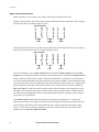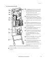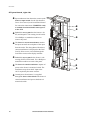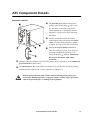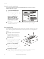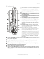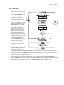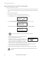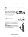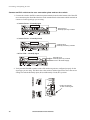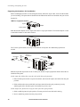
1
Smart Distribution Panel with ATS InfraStruXure Power Generation System 400V Operation Manual This manual is available in English on the enclosed CD. Uživatelská pøíruèka v èeštinì je k dispozici na pøiloženém CD. Dieses Handbuch ist in Deutsch auf der beiliegenden CD-ROM verfügbar. Deze handleiding staat in het Nederlands op de bijgevoegde cd. Este manual está disponible en español en el CD-ROM adjunto. Ce manuel est disponible en français sur le CD-ROM ci-inclus. A hasznalati utasitas magyarul megtalalhato a csatolt CD-n. Questo manuale è disponibile in italiano nel CD-ROM allegato. Denne manualen er tilgjengelig på norsk på vedlagte CD. Instrukcja Obsługi w jezyku polskim jest dostepna na CD. O manual em Português está disponível no CD-ROM em anexo. Данное руководство на русском языке имеется на прилагаемом компакт-диске. Denna manual finns tillgänglig på svenska på medföljande CD. Bu kullanim kilavuzunun Türkçe'sä, äläxäkte gönderälen CD äçeräsände mevcuttur. 您可以从包含的 CD 上获得本手册的中文版本。 About This Manual Audience This manual is intended for end-users of the InfraStruXure Smart Distribution Panel with ATS. It provides important safety warnings and instructions, an overview of the ATS components, a detailed discussion of the ATS display interface, instructions on how to add components to the ATS, product and warranty information, and technical specifications. Companion manuals For additional information about the ATS and the InfraStruXure Power Generation System, see the following InfraStruXure Power Generation System manuals: • ATS with Power Distribution Unpacking Sheet (990-1842) • Electrical Installation Manual (990-0596) • Generator Reference Manual (990-2334) • On-line Network Management User’s Guide (990-1993) How to find updates to this manual You can check for updates to this manual by clicking on the User Manuals link on the Support page of the APC Web site (www.apc.com). In the list of Power Generation System manuals, look for the latest letter revision (A, B, etc.) of the part number on the back cover of this manual. Smart Distribution Panel with ATS i Contents Safety ......................................................................1 Overview . . . . . . . . . . . . . . . . . . . . . . . . . . . . . . . . . . . . . . . . . 1 Save these instructions . . . . . . . . . . . . . . . . . . . . . . . . . . . . 1 Safety symbols used in this manual . . . . . . . . . . . . . . . . . . . 1 Cross-reference symbols used in this manual . . . . . . . . . . . . . 1 Warnings . . . . . . . . . . . . . . . . . . . . . . . . . . . . . . . . . . . . . . . . . 2 Read these instructions . . . . . . . . . . . . . . . . . . . . . . . . . . . 2 The InfraStruXure Power Generation System is an Optional Standby System . . . . . . . . . . . . . . . . . 2 Inspection and testing . . . . . . . . . . . . . . . . . . . . . . . . . . . . 2 Wire sizing . . . . . . . . . . . . . . . . . . . . . . . . . . . . . . . . . . . . 3 Installation . . . . . . . . . . . . . . . . . . . . . . . . . . . . . . . . . . . . 3 Total power off procedure . . . . . . . . . . . . . . . . . . . . . . . . . 3 Operating environment . . . . . . . . . . . . . . . . . . . . . . . . . . . 3 Overview .................................................................5 InfraStruXure Power Generation System . . . . . . . . . . . . . . . . . . 5 How the InfraStruXure Power Generation System Operates . . . . . . . . . . . . . . . . . . . . . . . . . . . 6 Operation of the ATS during a mains failure when automatic operation is enabled . . . . . . . . 6 Generator start sequence . . . . . . . . . . . . . . . . . . . . . . . . . . 7 Generator cool-down . . . . . . . . . . . . . . . . . . . . . . . . . . . . . 7 Open and closed transfers . . . . . . . . . . . . . . . . . . . . . . . . . 8 Fuel monitoring/runtime calculation . . . . . . . . . . . . . . . . . . . 9 Smart Distribution Panel with ATS . . . . . . . . . . . . . . . . . . . . . 11 Front view, door closed . . . . . . . . . . . . . . . . . . . . . . . . . . 11 Front view, door open . . . . . . . . . . . . . . . . . . . . . . . . . . . 12 ATS panel board, left side . . . . . . . . . . . . . . . . . . . . . . . . . 13 ATS panel board, right side . . . . . . . . . . . . . . . . . . . . . . . . 14 Smart Distribution Panel with ATS iii ATS Component Details . . . . . . . . . . . . . . . . . . . . . . . . . . . . . . 15 Motorized switches . . . . . . . . . . . . . . . . . . . . . . . . . . . . . 15 Automatic operation control panel . . . . . . . . . . . . . . . . . . . 16 User connection plate . . . . . . . . . . . . . . . . . . . . . . . . . . . 16 ATS monitoring unit . . . . . . . . . . . . . . . . . . . . . . . . . . . . 17 ATS label kit . . . . . . . . . . . . . . . . . . . . . . . . . . . . . . . . . . 18 Operation ............................................................. 19 Automatic Operation . . . . . . . . . . . . . . . . . . . . . . . . . . . . . . . . 19 How to place the InfraStruXure Power Generation System in automatic operation . . . . . . . . . . . . . 19 How to reset automatic operation on the ATS and on the generator . . . . . . . . . . . . . . . . . . . . . . 20 Problem—loss of automatic operation . . . . . . . . . . . . . . . . 21 Emergency Manual Operation . . . . . . . . . . . . . . . . . . . . . . . . . 22 Warning—before you operate the ATS manually . . . . . . . . . 22 How to power the load from the generator . . . . . . . . . . . . . 23 How to return to powering the load from mains . . . . . . . . . 25 Total Power Off . . . . . . . . . . . . . . . . . . . . . . . . . . . . . . . . . . . . 27 Display Interface.................................................... 29 Overview. . . . . . . . . . . . . . . . . . . . . . . . . . . . . . . . . . . . . . . . . 29 Top-level status screens . . . . . . . . . . . . . . . . . . . . . . . . . . 30 Top-level menu screen . . . . . . . . . . . . . . . . . . . . . . . . . . . 30 Navigating through screens . . . . . . . . . . . . . . . . . . . . . . . 31 Password-protected screens . . . . . . . . . . . . . . . . . . . . . . . 31 Load-Meter . . . . . . . . . . . . . . . . . . . . . . . . . . . . . . . . . . . . . . . 32 Total Load by Phase . . . . . . . . . . . . . . . . . . . . . . . . . . . . 32 Total Load Summary . . . . . . . . . . . . . . . . . . . . . . . . . . . . 32 Power Factor . . . . . . . . . . . . . . . . . . . . . . . . . . . . . . . . . 32 ATS/Voltage . . . . . . . . . . . . . . . . . . . . . . . . . . . . . . . . . . . . . . 33 ATS Position . . . . . . . . . . . . . . . . . . . . . . . . . . . . . . . . . . 33 S1-Utility . . . . . . . . . . . . . . . . . . . . . . . . . . . . . . . . . . . . 33 S2-Generator . . . . . . . . . . . . . . . . . . . . . . . . . . . . . . . . . 34 ATS Setup . . . . . . . . . . . . . . . . . . . . . . . . . . . . . . . . . . . 35 Generator . . . . . . . . . . . . . . . . . . . . . . . . . . . . . . . . . . . . . . . . 37 iv Smart Distribution Panel with ATS Testing . . . . . . . . . . . . . . . . . . . . . . . . . . . . . . . . . . . . . . . . . . 39 View Test Log . . . . . . . . . . . . . . . . . . . . . . . . . . . . . . . . . 39 Run/View Test . . . . . . . . . . . . . . . . . . . . . . . . . . . . . . . . 39 Test Schedule . . . . . . . . . . . . . . . . . . . . . . . . . . . . . . . . . 40 Test Duration . . . . . . . . . . . . . . . . . . . . . . . . . . . . . . . . . 40 How a test occurs . . . . . . . . . . . . . . . . . . . . . . . . . . . . . . 41 Stats . . . . . . . . . . . . . . . . . . . . . . . . . . . . . . . . . . . . . . . . . . . . 42 Alarms . . . . . . . . . . . . . . . . . . . . . . . . . . . . . . . . . . . . . . . . . . . 43 View Active Alarms . . . . . . . . . . . . . . . . . . . . . . . . . . . . . 43 Alarm/Event Log . . . . . . . . . . . . . . . . . . . . . . . . . . . . . . . 43 Alarm Setup . . . . . . . . . . . . . . . . . . . . . . . . . . . . . . . . . . 43 Alarm Beeper . . . . . . . . . . . . . . . . . . . . . . . . . . . . . . . . . 44 Clearing latched alarms . . . . . . . . . . . . . . . . . . . . . . . . . . 44 Config . . . . . . . . . . . . . . . . . . . . . . . . . . . . . . . . . . . . . . . . . . . 45 System/Network . . . . . . . . . . . . . . . . . . . . . . . . . . . . . . . 45 Contacts & Relays . . . . . . . . . . . . . . . . . . . . . . . . . . . . . . 46 Electrical Config . . . . . . . . . . . . . . . . . . . . . . . . . . . . . . . 47 Factory Defaults . . . . . . . . . . . . . . . . . . . . . . . . . . . . . . . 47 Manufacturer Data . . . . . . . . . . . . . . . . . . . . . . . . . . . . . 47 System ID . . . . . . . . . . . . . . . . . . . . . . . . . . . . . . . . . . . 47 Firmware updates . . . . . . . . . . . . . . . . . . . . . . . . . . . . . . 47 Communication Configuration ............................... 49 ATS Management Options . . . . . . . . . . . . . . . . . . . . . . . . . . . . 49 Overview . . . . . . . . . . . . . . . . . . . . . . . . . . . . . . . . . . . . 49 InfraStruXure Manager . . . . . . . . . . . . . . . . . . . . . . . . . . . 49 Network management interfaces . . . . . . . . . . . . . . . . . . . . 49 Configuring the InfraStruXure Manager . . . . . . . . . . . . . . . . . . 50 Configuring the ATS Network Management Interface. . . . . . . . 51 Connect the ATS to your network . . . . . . . . . . . . . . . . . . . 51 Configuration overview . . . . . . . . . . . . . . . . . . . . . . . . . . 52 TCP/IP configuration methods . . . . . . . . . . . . . . . . . . . . . . 52 Device IP Configuration Wizard . . . . . . . . . . . . . . . . . . . . . 52 BOOTP & DHCP configuration . . . . . . . . . . . . . . . . . . . . . . 53 Local access to the control console . . . . . . . . . . . . . . . . . . 55 Remote access to the control console . . . . . . . . . . . . . . . . . 55 Control console . . . . . . . . . . . . . . . . . . . . . . . . . . . . . . . 56 v Smart Distribution Panel with ATS How to Access the ATS Network Management Interface. . . . . . 57 Web interface . . . . . . . . . . . . . . . . . . . . . . . . . . . . . . . . . 57 Telnet and SSH . . . . . . . . . . . . . . . . . . . . . . . . . . . . . . . . 58 SNMP . . . . . . . . . . . . . . . . . . . . . . . . . . . . . . . . . . . . . . 58 FTP and SCP . . . . . . . . . . . . . . . . . . . . . . . . . . . . . . . . . . 59 How to Recover From a Lost Network Management Interface Password . . . . . . . . . . . . . . . . 60 Customizing and Updating the ATS ....................... 61 How to Connect User Input Contacts and Relay Outputs to the ATS . . . . . . . . . . . . . . . . . . . . . . . . . . . . . 61 Overview . . . . . . . . . . . . . . . . . . . . . . . . . . . . . . . . . . . . 61 How to connect contacts to the ATS user connection plate . . . . . . . . . . . . . . . . . . . . . . . . 62 How to Connect an EPO Switch to the ATS . . . . . . . . . . . . . . . 63 Overview . . . . . . . . . . . . . . . . . . . . . . . . . . . . . . . . . . . . 63 Connect an EPO switch to the user connection plate and test the switch . . . . . . . . . . . . . . 64 Safety warnings . . . . . . . . . . . . . . . . . . . . . . . . . . . . . . . 66 How to Allow Easy Access to the ATS Display Interface . . . . . . 67 How to Add Sub-Feed Output Distribution Circuit Breakers to the ATS. . . . . . . . . . . . . . . . . . . . . . . . . . . . 68 Output distribution circuit breakers available from APC . . . . . 68 Determine the configuration of the panel . . . . . . . . . . . . . . 69 Preparing the breakers for installation . . . . . . . . . . . . . . . . 70 Parts and tools needed for installation procedures . . . . . . . . 71 Installing breakers on the ATS panel board . . . . . . . . . . . . . 72 How to Update ATS Firmware . . . . . . . . . . . . . . . . . . . . . . . . . 73 Upgrading the ATS control processor . . . . . . . . . . . . . . . . . 73 Downloading firmware updates from a local computer . . . . . 74 Specifications ........................................................ 75 Warranty, Life-Support Policy, and Service ............. 79 Warranty. . . . . . . . . . . . . . . . . . . . . . . . . . . . . . . . . . . . . . . . . 79 Life-Support Policy . . . . . . . . . . . . . . . . . . . . . . . . . . . . . . . . . . 81 Service. . . . . . . . . . . . . . . . . . . . . . . . . . . . . . . . . . . . . . . . . . . 82 vi Smart Distribution Panel with ATS Appendix A: Custom Installations ...........................83 If Source 2 is a Second Mains Connection . . . . . . . . . . . . . . . . 83 If Source 2 is a Generator that is Not an APC InfraStruXure Generator . . . . . . . . . . . . . . . . . . . . 84 Smart Distribution Panel with ATS vii Safety Overview Save these instructions This manual contains important instructions that must be followed during installation, operation, and maintenance of the Smart Distribution Panel with ATS. Safety symbols used in this manual Indicates an electrical hazard, which, if not avoided, could result in injury or death. Elec tric al H d Indicates a hazard, which, if not avoided, could result in severe personal injury or substantial damage to product or other property. DANGER Indicates a heavy load that should not be lifted without assistance. Heavy Indicates important information. Note Cross-reference symbols used in this manual Indicates that more information is available on the same subject in a different section of this manual. Indicates that more information is available on the same subject in a different manual. See also Smart Distribution Panel with ATS 1 Warnings Read these instructions Note The components in the InfraStruXure Power Generation System and UPS power distribution system can pose life-threatening danger when improperly installed, operated, or maintained. To prevent accidents, be aware of the dangers and act safely. Read and follow all of the safety instructions and warnings in this manual and in all of your component manuals. The InfraStruXure Power Generation System is an Optional Standby System Note The generator and Automatic Transfer Switch (ATS) that you purchased from APC is classified as an Optional Standby System—it provides backup or standby power to data centers in the event of a sustained power failure. The InfraStruXure Power Generation System is not to be classified as an Emergency System that is essential for safety to human life (e.g., fire pumps, operating room, and life-support equipment in hospitals) as legally required by a municipal state, federal, or other governmental standards. The InfraStruXure Power Generation System is not to be classified as a Legally-Required Standby System as it is not supplying power to aid in fire fighting, rescue operations, control of health hazards (e.g., sewage) and similar operations as required by a municipal, state, federal, or other governmental standards. Emergency and Legally-Required Systems are not allowed to rely on municipal fuel for operation and municipal water for cooling. Emergency and Legally-Required Systems require dual fuel systems, with one of them being a two-hour, on-site fuel supply. Your InfraStruXure Power Generation System is not to be classified as an Integrated Electrical System as an orderly shutdown is not required to prevent damage to the generator. The generator is not to be paralleled with another generator. Your generator will operate at its rated load without being re-fueled for a minimum of six hours, and should run for a minimum of 12 hours. Your generator can be without electrical power to the load terminals of the transfer switch for 60 seconds maximum, but will typically be without power for no more than 10 seconds. Inspection and testing Note This ATS shall be inspected weekly and tested monthly by a competent service person. 2 Smart Distribution Panel with ATS Safety Wire sizing Note This product and this manual were designed for the 250-amp ATS. All wiring recommendations were sized for this amperage in accordance with IEC 60364-5-52. This does not prevent you from using the ATS at a lower current with smaller wire sizes. If you decide to operate this ATS at a lower current, ensure that the wire sizes are in accordance with IEC 60364-5-52 or your national standard. Installation Note For complete installation instructions, see the InfraStruXure Power Generation System Electrical Installation manual. See also Install this ATS in accordance with your national and local electrical standards. When connecting Source 1 to the ATS, install a circuit breaker to protect the ATS from overcurrent. This circuit breaker must be rated at 250A. Total power off procedure DANGER To reduce risk of electric shock or injury to persons, disconnect all sources of supply before servicing. To disconnect all sources of supply, follow this procedure: 1. Set the Automatic Operation switch on the deadfront of the ATS to Disable. 2. Set the Source 1 switch on the ATS to OFF. 3. Set the Source 2 switch on the ATS to OFF. 4. Set the main Source 1 circuit breaker to OFF. 5. Set the main Source 2 circuit breaker to OFF. 6. If Source 2 is a generator, set the generator control switch to OFF, or set the generator control switch to Manual, if OFF is not an option. Operating environment Note Indoor use only, protected from water and conductive contaminates. Temperature –5 to 40°C Humidity 0–95%, non-condensing Elevation 0–2000m Smart Distribution Panel with ATS 3 Overview InfraStruXure Power Generation System The InfraStruXure Power Generation System consists of a diesel-powered generator and a Smart Distribution Panel with ATS. The ATS is connected to mains (Source 1) and the generator (Source 2), with mains as the preferred source. The ATS is designed for the data center floor, which places the ATS and the power distribution closer to your data center equipment. Labels on the ATS provide quick visual indication of which ATS sub-feed breaker is supplying power to each piece of equipment. The diagram below provides examples of data center equipment that can be connected to the ATS. Air Conditioner Chiller InfraStruXure System/ UPS and Distribution Air Conditioner Circulator Pump Air Conditioner Condenser/OHE InfraStruXure Air Conditioner/ CRAC ATS Distribution Panel Source 2 Generator Source 1 Mains Service Entrance Panel Smart Distribution Panel with ATS 5 How the InfraStruXure Power Generation System Operates Operation of the ATS during a mains failure when automatic operation is enabled Typically, your data center equipment is powered by mains [Source 1] (), and the generator is off. When the Source 1 line quality is bad (), the ATS signals the generator to start ().When the generator starts, the ATS will perform an open transfer to generator (). The generator will run and support your data center equipment () until mains comes back on-line (). Once the mains has been of good and stable quality for the length of the Line Stable setting and the generator has run for the Min Gen Runtime setting, your data center equipment is once again powered by mains (). The re-transfer to mains can be either an open or closed transfer. After the re-transfer, the generator will cool down () and stop. For more information. See page 33 for a detailed description of how the ATS determines that the line quality is bad. See page 7 for a detailed description of the start sequence. See page 8 for a detailed description of an open and closed transfer. See page 7 for a detailed description of the generator cool-down. See page 35 for information about the Line Stable setting. See page 35 for information about the Min Gen Runtime setting. 6 Smart Distribution Panel with ATS Overview Generator start sequence The generator start sequence is followed only if the Crank setting in the Operating Settings menu on the Generator Settings screen on the ATS display interface menu is set to Yes. If it is enabled, the following sequence will occur: After a start signal is initiated, either by the ATS or manually, and the generator battery is good, the generator engine will crank and the generator should start. If the generator does not start, it will crank for the length of the Crank Time, and then rest for the length of the Rest Time. The generator will repeat this pattern for the number of times set in the Crank Cycles before stopping the attempt to start. Check the messages on the display interface for reasons why the generator did not start. On the generator controller interface, the LEDs track conditions during the start sequence: LED Behavior on the Generator Controller Interface Start sequence initiated: Generator Started: Generator Failed to Start: Generator cool-down After the load is powered by the generator, and mains returns and is powering the load, the generator may enter a cool-down period. If the coolant temperature is above the Coolant Temperature Limit, the generator will enter a cool-down period. During generator cool-down, the generator disconnects the alternator from the output and then runs at idle speed for 10 minutes. After the idle speed time expires, the generator will shut down. If the coolant temperature is not above the Coolant Temperature Limit, the generator will not enter a cool-down period but will shut down after mains returns and is powering the load. Smart Distribution Panel with ATS 7 Overview Open and closed transfers When a transfer is not occurring, one switch is ON and the second switch is OFF. During a closed transfer, the second switch will turn ON before the first switch turns OFF, creating a brief period of time when both switches are ON. Closed Transfer Source 1 Source 1 Source 2 Source 2 During an open transfer, the first switch will turn OFF before the second switch turns ON, creating a period of time when neither source is connected (neutral time). Open Transfer Source 1 Neutral Source 2 You can set whether or not to Allow Closed transfers under the Transfer Setup item on the ATS Setup menu on the display interface. (See page 35 for details on these settings.) If the Allow Closed setting is Yes, the ATS will always seek to perform closed transfers. In order for a closed transfer to occur, the voltage and frequency for both sources has to be good; in addition, a closed transfer cannot occur if the two sources are not synchronized. The ATS monitors for both sources to be synchronized before transferring. If the time it takes for the sources to be synchronized exceeds the configured Max Sync Time, the ATS will perform an open transfer instead. During a closed transfer, the ATS also takes into account the time it takes for the switch to actuate, which creates a seamless transfer— non-UPS-protected equipment will not be interrupted and the UPS time on battery will be reduced, and in some cases, eliminated. If the Allow Closed setting is No, the ATS will never perform closed transfers—it will always perform open transfers. (See page 35 for details on these settings.) During an open transfer, the first switch will turn OFF before the second switch turns ON, creating a period of time when neither source is connected. This period is commonly referred to as the neutral time. The neutral time is defined by the configurable Open Xfer Time. 8 Smart Distribution Panel with ATS Overview Fuel monitoring/runtime calculation Fuel monitoring is a unique feature of the InfraStruXure Power Generation System. Fuel level is monitored at the generator (if purchased through APC) and load is measured at the ATS. These measurements are used to calculate runtime, as explained in the following paragraph. Fuel is monitored by a level sensor in the generator fuel tank (calibrated to the bottom of the fuel tank) that changes readings every 12.7 millimeters of fuel level change. From these fixed level points, the ATS counts the number of liters of fuel used (based on load over time) and subtracts this from the fixed-level fuel amount to give an accurate estimate of fuel level. The remaining runtime is then calculated based on the fuel usage rate at the current load and the remaining fuel in the tank. Once a new fuel level point is reached, the value of the calculated fuel used is reset and the computation begins again. The Fuel Level and Runtime Estimate are displayed on the Generator Status screen on the ATS display interface, and you can set the following Fuel Alarm Limits in the Alarms menu of the display interface: Percent Fill: If the amount of fuel as a percentage falls below this value, an alarm condition exists. Runtime: If the estimated runtime falls below this value, an alarm condition exists. Smart Distribution Panel with ATS 9 Smart Distribution Panel with ATS Front view, door closed Twenty knockouts are provided on the roof, the sides, and on the floor of the ATS for running mains and generator conductors and for distributing power to equipment in your data center. Connecting cable to the ATS does not require drilling; use a knockout punch to enlarge a knockout, if necessary. The user connection plate is connected to the ATS monitoring unit, and provides easy access to input contact, relay output, network, and EPO connections. Make connections from inside the enclosure, and route wires through the knockout provided on the plate. See “User connection plate” on page 16 for more information. The bottom access panel can be removed for access to the panel board. Use a #2 Phillips screwdriver to remove the two M6 flat-head screws securing the panel to the enclosure. The perforated steel front door has a Plexiglas plate protecting access to the switches and circuit breakers. Also included is a rectangular piece of Plexiglas to cover the display interface. Install the piece of plexiglass if you want to prevent access to the display interface through the front door. See page 67 for installation instructions. Smart Distribution Panel with ATS 11 Overview Front view, door open The deadfront provides access to the panel board for maintenance and wiring. The Source 1 input is controlled by the Source 1 motorized switch. See “Motorized switches” on page 15 for more information on the operation of this switch. The automatic operation control panel sets whether the generator is controlled automatically. See “Automatic operation control panel” on page 16 for more information. The Source 1 lamp is green when the Source 1 switch is ON (closed). The display interface provides a local interface for viewing status data, configuring settings, and operating the ATS. It has an LCD, five-button interface, basic status lights, and a beeper. See “Display Interface” on page 29 for detailed information on operation and the contents of each screen. The captive screw secures the deadfront, and can be loosened with a Phillips or standard screwdriver. Sub-feed output breakers power equipment in the data center. For detailed information on installing these breakers, see page 68. The Source 2 lamp is green when the Source 2 switch is ON (closed). The Source 2 input is controlled by the Source 2 motorized switch. See page 15 for more information on how to operate this switch. The latches open the deadfront after the captive screw in the middle right side of the deadfront is loosened with a Phillips or standard screwdriver. 12 Smart Distribution Panel with ATS Overview ATS panel board, left side The handle aids the optional removal of the panel board from the ATS enclosure. Use at least two people to remove the panel board from the ATS enclosure. See the InfraStruXure Power Generation System Installation Manual for instructions. Control power from Source 1 is supplied through the Source 1 fuse block to the Source 1 control transformer for powering the Source 1 motorized switch and the ATS monitoring unit. The Source 1 control transformer outputs AC power to the Source 1 motorized switch, and the ATS monitoring unit. The transformer steps down 400V input. The communication converter allows the generator and ATS to communicate. The ATS has several monitoring boards that report to a central board assembly located in the ATS monitoring unit. See “ATS monitoring unit” on page 17 for detailed information. Behind this access panel is the ATS interface circuit board. Use a Phillips or standard screwdriver to remove the panel. Input conductors from the generator connect to the Source 2 input switch. See the InfraStruXure Power Generation System Electrical Installation Manual for connection instructions. WARNING: Only a certified electrician should connect the generator to the ATS! The wheel assembly on the panel board allows for easy removal of the panel board during unpacking. Smart Distribution Panel with ATS 13 Overview ATS panel board, right side Input conductors from the mains connect to the Source 1 input switch. See the InfraStruXure Power Generation System Installation Manual for connection instructions. WARNING: Only a certified electrician should connect power to the ATS! Behind this access panel are the Source 1 (S1 PT) and Output PT volt-sensing circuit boards. Use a Phillips or standard screwdriver to remove the panel. The Source 1 current transformers monitor the input current from each phase of the input from the mains. The data gathered from these current transformers is displayed on the Total Load by Phase screen, accessed through the Load Meter menu on the display interface. Behind this access panel is the Source 2 voltsensing (S2 PT) circuit board. Use a Phillips or standard screwdriver to remove the panel. The Source 2 control transformer outputs AC power to the Source 2 motorized switch. The transformer steps down 400V input to the 120V required by the motor actuator. Control power from Source 2 is supplied through the Source 2 fuse block to the Source 2 control transformer and powers the Source 2 motorized switch. 14 Smart Distribution Panel with ATS ATS Component Details Motorized switches The operating lever indicates the present position of the switch [OFF ( ), trip, or ON ( )]. This lever is also used to operate the switch manually. See “Emergency Manual Operation” on page 22 for proper operating procedures. Choose whether the motorized switch is controlling the input switch using the selector switch. Use only during emergency manual operation. See page 21 for more information. Pressing the trip test button immediately turns the switch to trip, and, when automatic operation is enabled, the operating lever swings to the OFF () position. WARNING: Do not press this button while load is connected! When the motorized switch is in the OFF () position, attach a lock-out tag to the withdrawal prevention lock for added safety. The operating lever key is provided in the hardware bag with the ATS. Use the key during manual operation of the switch to easily control the operating lever. DANGER Do NOT operate the motorized switches without following the instructions in “Emergency Manual Operation” on page 22. Failure to follow proper procedures could cause personal injury or damage to the equipment. Smart Distribution Panel with ATS 15 Overview Automatic operation control panel For a discussion of Automatic Operation of the InfraStruXure Power Generation System, see “Automatic Operation” on page 19. The Not in Automatic Operation LED is lit when the ATS is NOT in automatic operation, typically when the automatic operation switch is in the Disable position. However, in rare instances, the Not in Automatic Operation LED can be lit when the automatic operation switch is in the enable position. See page 21 for more information. Select whether the generator will automatically turn on after a loss of power using the Automatic Operation switch. User connection plate For a description and the location of the user connection plate, see number 2 on page 11. For clarity, the user connection plate in the illustration below is turned upside-down from its factory-installed position. Connect the ATS to the network or the InfraStruXure Manager through the surge-protected ethernet port. This port protects your network connection from power surges. The user connection plate has four input contact connections for monitoring Normally Open (NO) or Normally Closed (NC) dry contacts. See page 46 and page 61 for more information. The user connection plate has four relay output connections for connection of NO or NC dry contacts. See page 46 and page 61 for more information. Connect an Emergency Power-Off switch at one of three choices of EPO Connections (24VDC, 24VAC, or contact closure). See page 63 for more information. 16 Smart Distribution Panel with ATS Overview ATS monitoring unit This port connects to the Source 2 volt-sensing (S2 PT) circuit board, Source 1 volt-sensing (S1 PT) circuit board, Source 1 current transformers, and distribution panel volt-sensing output circuit board. This port connects to the ATS interface circuit board. The display port (RJ-45) connects the monitoring unit to the display interface. The power LED indicates whether the monitoring unit is receiving power. This console port is used to configure items relating to servicing and for communicating with the generator (see item 4 on page 13). Use this port (DB-9) to connect a laptop computer to the monitoring unit using an appropriate communication cable (APC part number 940-0103). EPO DIP switches configure the EPO input for the type of EPO switch that is connected—Normally Open (NO) or Normally Closed (NC). When the EPO Arm/Test rocker is in the Test position, engaging the EPO switch will not cause the load to be powered off. When the rocker is in the Armed position, engaging the EPO switch turns OFF the ATS Source 1 and Source 2 switches and engages the generator’s emergency stop button. When the EPO switch is engaged, the ATS Not in Automatic LED is lit. See page 64 for more information on testing the EPO switch. The EPO Armed LED is green when the rocker is in the Armed position. The LED is dark when the rocker is in the Test position. The EPO Tripped LED is red when the EPO switch is engaged (the EPO button is pressed), regardless of the state of the EPO Arm/Test rocker. The reset button resets the network processor; it does not reset the ATS or the monitoring unit. This network port connects to the surge-protected ethernet port on the user connection plate. (See page 16 information on the surge-protected ethernet port.) This port connects to the ATS interface circuit board. The optional User/EPO Contacts port is connected to the User Connection Plate in the roof of the ATS. The port allows for relay outputs (4), input contacts (4), and an EPO input (1). See page 16 for more information. Smart Distribution Panel with ATS 17 Overview ATS label kit ATS Label—Place this label on the outside of the ATS enclosure to identify the ATS, and to associate it with the appropriate source 1 and source 2. Source Label—Use a Source 1 label at the primary mains breaker to identify the ATS that it is connected to. Use a Source 2 label if you are connecting to a secondary mains breaker instead of a generator. Generator Label—Use three of these labels at the generator to identify which ATS it is connected to. Place one label on each long side of the generator near the generator brand name labels, and place one label on the door where the generator controller is located. Single-Pole Label—Use one of these labels with a single-pole breaker on the ATS distribution panel to identify to what equipment the breaker is feeding power. Use the marker (included) to write on the label. Three-Pole Breaker Label—Use one of these labels with a three-pole breaker on the ATS distribution panel to identify to what the breaker is feeding power. Use the marker (included) to write notes on the lower portion of the label. The labels are customized for typical components in an InfraStruXure system. Blank labels are also included for components that do not have pre-marked labels. Front Bezel Label—If you are not using a generator for source 2, use one of these labels to replace the Generator Power System label on the left-hand side of the bezel. You can use either the Automatic Transfer Switch or the Standby Power System label to describe your system. ATS Deadfront Source Label—Use these alternate labels for source 1 and source 2 if you do not want Mains and Generator to describe your sources. Using these labels, you can use Primary and Secondary or Normal and Alternate to describe source 1 and source 2. 18 Smart Distribution Panel with ATS Operation Automatic Operation How to place the InfraStruXure Power Generation System in automatic operation 1. Ensure that mains is available. The generator will be signaled to start if mains is not available. 2. Ensure that the /Manual/Auto switch on the generator control panel is in the Auto position. 3. Set the ATS Automatic Operation switch to Enable. 4. Check that the Not In Automatic Operation LED is not lit. See page 21 for information on uncommon behavior of this LED. “How the InfraStruXure Power Generation System Operates,” beginning on page 6, provides a detailed summary of automatic operation of the InfraStruXure Power Generation System. Smart Distribution Panel with ATS 19 Operation How to reset automatic operation on the ATS and on the generator Resetting automatic operation on the ATS. If the Not in Automatic Operation LED is lit and the Automatic Operation switch is in the Enable position, you need to reset automatic operation after the event that caused this condition has been corrected. (See page 21 for a detailed description of the events that might lead to this condition.) You can also clear certain alarms by resetting automatic operation on the ATS. See “Clearing latched alarms” on page 44 for more information. To reset automatic operation on the ATS, set the Automatic Operation switch to Disable () and then back to Enable (). Resetting automatic operation on the generator. If the ATS display interface reports a generator shutdown alarm and the Alarm LED is red, you must reset automatic operation on the generator to clear the alarm (the Shutdown LED on the generator control panel will also be red). Events that lead to this condition include engaging the data center EPO switch and engaging the E-Stop button on the generator. If any EPO was engaged, the switch must be disengaged before automatic operation can be reset. If shutdown was not caused by EPO, contact APC service (see “Service” on page 82). To reset automatic operation on the generator: Set the /Manual/Auto switch on the generator control panel to . Press the Fault Acknowledge/Reset button on the generator control panel. Set the /Manual/Auto switch on the generator control panel back to Auto. 20 Smart Distribution Panel with ATS Operation Problem—loss of automatic operation Typically, the Not In Automatic Operation LED tracks the state of the Automatic Operation switch (i.e., the LED is lit when the Automatic Operation switch is in the Disable position). If the Not In Automatic Operation LED is lit while the Automatic Operation switch is in the Enable position, check messages on the display interface to determine the cause—one of the following conditions exist: 1. The ATS attempted to actuate either the Source 1 or Source 2 switch, and could not. When a switch cannot actuate, one of the four following actions cannot take place: – The Source 1 switch cannot turn ON (Close) – The Source 1 switch cannot turn OFF (Open) – The Source 2 switch cannot turn ON (Close) – The Source 2 switch cannot turn OFF (Open) When the ATS cannot actuate a switch, it will attempt several more times before stopping. There are two cases of this condition: – The load is receiving supply from mains, and the Source 1 switch trips. When the Source 1 switch trips, the ATS will try to re-close the switch. If the switch cannot be closed the ATS will start the generator and then close the Source 2 switch. The load will be powered by the generator and the ATS will be in Not in Automatic Operation mode until it is reset (see page 20). – The load is receiving supply from the generator, and the Source 2 switch trips. When the Source 2 switch trips, the ATS will try to re-close the switch, and after several attempts one of two things will happen, depending upon whether mains is available. • If mains is not available, the generator will continue to run until mains is available. Once mains is available, the ATS will switch to mains and then turn off the generator. Mains will supply power to the ATS, and the ATS will be in Not in Automatic Operation mode until automatic operation is reset (see page 20). • If mains is available, the ATS will switch to mains and then turn off the generator. Mains will supply power to the ATS, and the ATS will be in Not in Automatic Operation mode until automatic operation is reset (see page 20). 2. The data center EPO switch that is connected to the ATS EPO interface was engaged. When the EPO switch is engaged, the ATS Source 1 and Source 2 switches are tripped open, and the generator’s emergency stop signal is engaged—the ATS is no longer supplying output power. The ATS immediately goes into Not in Automatic Operation mode. The ATS stays in Not in Automatic Operation mode until the system is reset. To reset the system, disengage the data center EPO switch and reset automatic operation on the generator and on the ATS (see page 20). Smart Distribution Panel with ATS 21 Emergency Manual Operation Warning—before you operate the ATS manually The procedures in this section only apply to situations where automatic operation through the ATS is impossible. One example of such a situation is if the ATS monitoring unit were not functioning. If automatic operation through the ATS is impossible, and you must power your load from the generator, follow the instructions in “How to power the load from the generator” on page 23. Note DANGER 22 Only operate the ATS switches manually when automatic operation is disabled. If automatic operation is enabled, the ATS will attempt to actuate the switches to return to the preferred source. All transfers performed when automatic operation is disabled must be open transfers—both switches must be OFF before turning ON the desired source’s switch. Attempting a closed transfer will damage equipment. Smart Distribution Panel with ATS Operation How to power the load from the generator 1. Place the ATS Automatic Operation switch in the Disable position. 2. Ensure that the Source 2 switch on the ATS is OFF (). 3. At the generator: a. Place the /Manual/Auto switch on the generator control panel in the Manual position. b. Press the Manual Run/Stop button on the generator control panel, if you need to start the generator. Pressing this button activates the engine control system and the starting system. The starter will begin cranking and, after a few seconds, the engine should start. Press 4. Turn the Source 1 switch on the ATS to OFF (): a. Set the selector switch on the Source 1 switch to Manual. The operating lever will swing out when the selector switch is in Manual. b. Turn the Source 1 switch to OFF (). You can use the operating lever key (provided), for easier operation. Smart Distribution Panel with ATS 23 Operation 5. Turn the Source 2 switch to ON ( ): a. Set the selector switch on the Source 2 switch to Manual. The operating lever will swing out when the selector switch is in Manual. b. Turn the Source 2 switch clockwise to ON ( ). You can use the operating lever key (provided), for easier operation. c. Close the operating levers on both the Source 1 and Source 2 switches, and set the selector switches back to Auto to lock the switches in place. 6. Ensure that the generator is powering the load by checking that the downstream UPS is no longer on battery operation or that other load equipment is operating. 7. Check the alarms visible on the control panel of the generator. 24 Smart Distribution Panel with ATS Operation How to return to powering the load from mains 1. Ensure that the ATS Automatic Operation switch is in the Disable position. 2. Ensure that the Source 1 switch on the ATS is OFF (). 3. Turn the Source 2 switch on the ATS to OFF (): a. Set the selector switch on the Source 2 switch to Manual. The operating lever will swing out when the selector switch is in Manual. b. Turn the Source 2 switch counterclockwise to OFF (). You can use the operating lever key (provided), for easier operation. 4. Turn the Source 1 switch on the ATS to ON ( ): a. Set the selector switch on the Source 1 switch to Manual. The operating lever will swing out when the selector switch is in Manual. b. Turn the Source 1 switch clockwise to ON ( ). You can use the operating lever key (provided), for easier operation. c. Close the operating levers on both the Source 1 and Source 2 switches, and set the selector switches back to Auto to lock the switches in place. Smart Distribution Panel with ATS 25 Operation 5. Turn off the generator by following this procedure: a. Ensure that the /Manual/Auto switch on the generator control panel is in the Manual position. b. Press the Manual Run/Stop button on the generator control panel. Pressing this button causes the generator to complete its normal shutdown sequence. 26 Press Smart Distribution Panel with ATS Total Power Off To reduce risk of electric shock or injury to persons, disconnect all sources of supply before servicing by following this procedure: 1. Set the ATS Automatic Operation switch to Disable. 2. Set the Source 1 switch on the ATS to OFF (): a. Set the selector switch on the Source 1 switch to Manual. The operating lever will swing out when the selector switch is in Manual. b. Turn the Source 1 switch counterclockwise to OFF (). You can use the operating lever key (provided), for easier operation. Smart Distribution Panel with ATS 27 Operation 3. Set the Source 2 switch on the ATS to OFF (): a. Set the selector switch on the Source 2 switch to Manual. The operating lever will swing out when the selector switch is in Manual. b. Turn the Source 2 switch counterclockwise to OFF (). You can use the operating lever key (provided), for easier operation. 4. Set the main Source 1 circuit breaker to OFF (). 5. Set the main Source 2 circuit breaker to OFF (). If Source 2 is a generator, set the generator control switch to OFF (), or set the generator control switch to Manual, if OFF is not an option. 28 Smart Distribution Panel with ATS Display Interface Overview You can use the display interface to configure settings, set alarm thresholds, and provide audible and visual alarms. Load On LED When green, all output phases are within the limits specified by the output alarm limit thresholds. Check Log LED When yellow, at least one new alarm condition has been detected. Gen Set On LED When green, the generator is running. Alarm LED When red, an alarm condition exists. LCD View alarms, status data, instructional help, and configuration items. Up and Down navigation keys Selects menu items and accesses information. ENTER key Opens menu items and inputs changes to system parameters. HELP key Launches context-sensitive help. Press the HELP key for information about each item on the screen and for instructions on how to perform certain tasks. ESC key Returns to previous screen displayed. Smart Distribution Panel with ATS 29 Display Interface Top-level status screens After start-up, a the interface displays a brief introduction screen and then scrolls automatically and continuously through five screens of basic status information. Press the Up and Down arrow keys to interrupt the automatic scrolling to view a specific status screen. Source: S1-Utility S2: OFF S1: Ok Fuel: xxx% Runtime: 1 day 12 hr Total Output Loading kW: 000 PF: 000 %LD: xxx kVA: 000 Freq: 000 Load Current: L1: 000 L2: 000 L3: 000 Volts-Out L1-2: xxx L2-3: xxx L3-1: xxx Neut:000 Volts-Sx L1-2: xxx L2-3: xxx L3-1: xxx No Active Alarms System Date/Time: Jun-24 2004 07:58 If you have scheduled tests, each time a self-test is commencing, the scheduled test screen (shown below) is displayed. To cancel this instance of the self-test, press the ENTER key when the selector arrow rests on the ABORT NOW? option. Scheduled test will start in xxx sec. ABORT NOW? Top-level menu screen On any top-level status screen, press the ENTER key to open the top-level menu screen. Load-Meter ATS/Voltage Generator Testing Stats Alarms Config Help If the display interface is inactive for the time specified as the Time-out setting, the interface reverts to the initial basic monitoring screens. Note For descriptions of the top-level menu choices, see the individual sections starting on page 32. 30 Smart Distribution Panel with ATS Display Interface Navigating through screens To open any screen, press the Up and Down arrow keys until the selector arrow ( rests next to your desired selection. Press the ENTER key to view the selected screen. Load-Meter ATS/Voltage Generator Testing Stats Alarms Config Help Contacts In: 02of04 Name: User Switch #2 Normal: Open Status: Open When configuring settings, press the Up and Down arrow keys until the selector arrow ( rests next to the setting you want to change, and press the ENTER key. If the setting is a list of choices, an input arrow ( will appear next to the setting. Press the Up and Down arrow keys until your desired change is listed. Press the ENTER key to select the setting. On some screens, continue arrows ( indicate that there are additional screens to view in the category. Press the Up or Down arrow key to view the additional screens. Contacts In: 02of04 Name: User Switch #2 Normal: Open Status: Open System/Network Electrical Configuration Panel Configuration Manufacturer Data Product Data Factory Defaults Firmware Updates Password-protected screens When configuring or changing settings, you will be prompted for your password. To enter your password: 1. Press the Up or Down arrow key until the correct letter is displayed, and then press the ENTER key. Note After you press the ENTER key, the character you entered is displayed as an asterisk and the input arrow moves to the next space for you to select the next password character. Enter Password: ******* 2. Press the ENTER key twice after you enter your password. See “System Password” on page 45 to change your password. Smart Distribution Panel with ATS 31 Load-Meter Total Load by Phase Total Load Summary Power Factor Sub-Feed Monitoring Total Load by Phase For each phase (L1, L2, L3) the following information is displayed: kVA The apparent power provided, in kilovolt amps. Iout The output RMS load current. %LD The load as a percentage of the maximum allowable load. Total Load Summary For the total load supported, the following information is displayed: kW The active power drawn by the load, in kilowatts. kVA The apparent power provided, in kilovolt amps. Freq The frequency, in hertz. PF Power factor, the ratio between active power and apparent power (kW/kVA), which affects the power available to the load. %LD The load as a percentage of the maximum allowable load. Power Factor Displays the following power factor data for each phase (L1, L2, L3): 32 kVA The apparent power provided, in kilovolt amps. kW The active power drawn by the load, in kilowatts. PF The ratio between active power and apparent power (kW/kVA), which affects the power available to the load. Smart Distribution Panel with ATS ATS/Voltage ATS Position: S1 S1-Utility: OK S2-Generator: OFF ATS Setup ATS Position One of the following options is displayed to describe the selected source: S1 The Source 1 switch is ON (closed). Source 1 is connected to the output. S2 The Source 2 switch is ON (closed). Source 2 is connected to the output. NEUT The Source 1 and Source 2 switches are OFF (open). Neither source is connected to the output. S1&S2! The Source 1 and Source 2 switches are ON (closed). This is an alarm condition. S1-Utility One of the following is displayed to describe the condition of the input from Source 1. OK Source 1 is acceptable, as defined in the Transfer Points menu. See page 35. BAD Source 1 is not acceptable, as defined in the Transfer Points menu. See page 35. Press the ENTER key when the selector arrow rests at the S1-Utility item to display the following: L1-2, L2-3, L3-1 The Source 1 line-to-line input voltage in volts (V). L1, L2, L3 The Source 1 line-to-neutral input voltage in volts (V). These readings are only displayed on WYE systems. Frequency The frequency of the mains input, in hertz (Hz). Qual Describes the quality of the input from Source 1. One of the following conditions is displayed: • Source Good: The source is acceptable, as defined in the Transfer Points menu. • Low Voltage: The input voltage is below the configured Low voltage Transfer Point on one or more of the phases. • High Voltage: The input voltage exceeds the configured High voltage Transfer Point on one or more of the phases. • Phase Imbalance: The percent voltage difference between two phases, as defined by the Phase Balance setting in the Transfer Points menu, has been exceeded. • Freq Range: The frequency is outside the configured Freq range, as defined in the Transfer Points menu. • Bad Rotation: The phase rotation does not match the configured Phase Sequence, as defined in the Transfer Points menu. Phase Sequence Lists the phase rotation of the Source 1 input. Smart Distribution Panel with ATS 33 Display Interface S2-Generator One of the following is displayed to describe the condition of the input from Source 2. OK Source 2 is acceptable, as defined in the Transfer Points menu. (The generator is running.) OFF The generator is not running. BAD Source 2 is not acceptable, as defined in the Transfer Points menu, while the ATS is commanding the generator to run. Press the ENTER key when the selector arrow rests at the S2-Generator item to display the following: L1-2, L2-3, L3-1 The Source 2 line-to-line input voltage in volts (V). L1, L2, L3 The Source 2 line-to-neutral input voltage in volts (V). These readings are only displayed on WYE systems. Frequency The frequency of the Source 2 input, in hertz (Hz). Qual Describes the quality of the input from Source 2. One of the following conditions is displayed: • Source Good: The source is acceptable, as defined in the Transfer Points menu. • Low Voltage: The input voltage is below the configured Low voltage Transfer Point on one or more of the phases. • High Voltage: The input voltage exceeds the configured High voltage Transfer Point on one or more of the phases. • Phase Imbalance: The percent voltage difference between two phases, as defined by the Phase Balance setting in the Transfer Points menu, has been exceeded. • Freq Range: The frequency is outside the configured Freq range, as defined in the Transfer Points menu. • Bad Rotation: The phase rotation does not match the configured Phase Sequence, as defined in the Transfer Points menu. Phase Sequence Lists the phase rotation (e.g., A-B-C) of the Source 2 input. 34 Smart Distribution Panel with ATS Display Interface ATS Setup Press the ENTER key when the selector arrow rests at the ATS Setup item to change the following settings: Transfer Points The point, when sensing the voltage, that you would transfer to the other source. Based on voltage and frequency. • S1-Utility: The input voltage reading for Source 1. • Low: The low voltage limit that causes the ATS to switch from Source 1 to Source 2. Press the ENTER key to change this setting. • High: The high voltage limit that causes the ATS to switch from Source 1 to Source 2. Press the ENTER key to change this setting. • Other Settings: The settings on this screen determine when the source is OK, and define the quality of the source. Press the ENTER key when the selector arrow rests at this item to change the following settings, or thresholds: – Freq: The frequency cannot vary beyond this configured range (+/– x.xx Hz). – Phase Balance: The percent voltage difference between two phases cannot exceed this configured setting (%). – Phase Sequence: The phase rotation (default is A-B-C) must match this configured setting. Transfer Setup The following settings can be changed in this menu: • Open Xfers: Defines the how long BOTH the Source 1 and Source 2 switches will be OFF (open) during an open transfer. See page 8 for a definition of open transfers. • Allow Closed: Enables/disables closed transfers. See page 8 for a definition of closed transfers. • Max Sync: The maximum time the ATS attempts a closed transfer before it performs an open transfer. • ATS Delay Settings: The time delay settings that affect transfers and re-transfers. – Gen Start: The amount of time between when the generator receives a start signal and when the generator starts (default is 0). – Line Stable: If the ATS switches to Source 2 after a failure in Source 1, and Source 1 is restored, the Line Stable setting is the amount of time (in seconds) that Source 1 has to be good for before returning to Source 1 (default is 3 minutes). – Min on Gen: The minimum time that the generator must run before the ATS re-transfers to mains (default is 15 minutes). Smart Distribution Panel with ATS 35 Display Interface ATS Blocking • Transfer Blocking: Defines conditions that will prevent the ATS from transferring from Source 1 to Source 2. The following is displayed on the Transfer Blocking screen: – Block Transfer: Lists configured input contacts that keep a transfer from occurring. – Map: Choose from the following input contacts that will block a transfer: C1: Contact 1 C2: Contact 2 C3: Contact 3 C4: Contact 4 – Apply Now: After you have made changes on this screen, choose this option and press the ENTER key to save your changes. • Retransfer Blocking: Defines conditions that will prevent the ATS from transferring from Source 2 to Source 1. The following is displayed on the Retransfer Blocking screen: – Block Re-Transfer: Lists configured input contacts that keep a re-transfer from occurring. Map: Choose from the following input contacts that will block a re-transfer: C1: Contact 1 C2: Contact 2 C3: Contact 3 C4: Contact 4 – Apply Now: After you have made changes on this screen, choose this option and press the ENTER key to save your changes. • Gen Start Blocking: Defines input contacts that will prevent the generator from starting because of a line failure: – Block Gen Start: Lists configured input contacts that prevent the generator from starting. – Map: Choose from the following input contacts that will block the generator from starting: C1: Contact 1 C2: Contact 2 C3: Contact 3 C4: Contact 4 – Apply Now: After you have made changes on this screen, choose this option and press the ENTER key to save your changes. Other Settings • S1 Name: Create a unique name for Source 1 (maximum of 9 characters). The default is Utility. • S2 Name: Create a unique name for Source 2 (maximum of 9 characters). The default is Generator. • Preferred: Displays the preferred source (Source 1). 36 Smart Distribution Panel with ATS Generator Generator Status Fuel & Runtime Statistics & Maint. Generator Settings Generator Status The following items are available on this menu: Generator Status One of the following conditions is displayed to describe the Gen State: • Off: The generator is not running. • Cranking: The generator is starting. • Running: The generator is running. • Idle: The generator is running, but not powering the load. • E-Stop: The Emergency Power Off switch has been actuated on the generator or ATS. • Fault: The generator is unable to start. • No Com: The ATS has lost communication with the generator. The Mode Sw is the position of the generator’s /Manual/Auto switch. The switch must be in Auto for the generator to be started based on the state of the run/stop contact. Auto, Manual, or Off is displayed to describe the position of the switch. The following settings can be accessed through this menu: • Engine Run: This is the current state of the run/stop contact, which signals the generator's engine to start and stop. The state can be Run or Off. Automatic control of this signal is disabled when the Not in Automatic Operation LED on the ATS is lit. • Engine Parameters: View the following measured data related to the generator's engine operation: – Engine RPM – Battery Voltage Fuel & Runtime – Oil Pressure – Coolant Level – Coolant Temperature – Oil Level The following are displayed on this screen: • Type: The type of fuel that the generator uses (diesel). • Tank Size: The size of the fuel tank on the generator (in gallons). • Fuel Level: The percentage of fuel left in the generator fuel tank. Statistics & Maint. • Runtime Estimate: How much time (xx days zz hours) the generator can run based on the fuel level and load, and the load value, in kW, used to calculate runtime. • Lifetime Statistics: Scroll through a list of items that accumulate over the life of the generator, including: – Last Maintenance Date – Engine Starts – Total kWh – Total Runhours Smart Distribution Panel with ATS 37 Display Interface • Maintenance Record: Scroll through a list of items that accumulate after the maintenance record is reset, including: – Last Maintenance Date – Operating Days – Engine Starts – Total kWh – Total Runhours • Next Maintenance: View the month and year of the next scheduled maintenance and the number of days until the scheduled maintenance, and clear the maintenance record so that the data in the menu, Maintenance Record, is reset to zero. Generator Settings The following settings are accessible through this screen: • Operating Settings – Start Delay The amount of time that the generator waits after the start signal is initiated before the generator starts and powers the load. (Configurable on the generator control panel.) – Stop Delay The amount of time between when the start signal is removed and when the generator stops. (Configurable on the generator control panel.) – Crank Settings The following settings can be changed in the generator service menus by generator service personnel. • Crank: Whether the crank cycle is enabled. If the crank cycle is not enabled, the generator will attempt to start until the battery dies. • Crank Cycles: The number of crank cycles that the generator will go through when attempting to start the generator. The default setting is three. • Crank Time: The amount of time that the generator will crank during a crank cycle. The default setting is 15 seconds. • Rest Time: The amount of time that the generator will rest after it cranks during a crank cycle. The default setting is 15 seconds. • Manufacturer Data – Fuel System – Tank Size – Final Assy Date – Model Number – GenSet S/N – Voltage Config – Alternator Freq – Gen kW Rating • Gen Output Adjust – Voltage – Frequency 38 The type of fuel that the generator uses (default is diesel). The size of the fuel tank on the generator (in Liters). Date that the generator was assembled at the factory. Generator model number from Cummins®. The serial number of the generator. Nominal input voltage (400V). Nominal frequency setting of the alternator output (50Hz). The power rating of the generator (88kW, 131kW, 182kW). Displays the desired alternator output voltage (configurable on the generator control panel). Displays the desired alternator output frequency (configurable on the generator control panel). Smart Distribution Panel with ATS Testing View Test Log Run/View Test Test Schedule Test Duration View Test Log Displays all logged test results in a scrolling list. For each item in the list, the screen lists the Gen Start test and the Load Test results with a date and time stamp of when the test occurred. Run/View Test Use this menu to run a test now, or to view a test that is in progress. Engine Start Test If a test is in progress, the screen displays the Test Progress and the time remaining in the test. If you want to stop the test, select the ABORT NOW? item on this screen and press the ENTER key. If you want to run a start test now, select Run Test Now from the confirmation screen, and then press the ENTER key. The test will run based on the parameters set on the Test Duration menu. If you do not want to run a start test now, choose No from the confirmation screen, and then press the ENTER key. System Load Test If a test is in progress, the screen displays the Test Progress and the time remaining in the test. If you want to stop the test, select the ABORT NOW? item on this screen and press the ENTER key. If you want to run a load test now, select Run Test Now from the confirmation screen, and then press the ENTER key. The test will run based on the parameters set on the Test Duration menu. If you do not want to run a load test now, choose No from the confirmation screen, and then press the ENTER key. Smart Distribution Panel with ATS 39 Display Interface Test Schedule Use this menu to schedule a test in the future. Define Schedule Set the test schedule by changing the following parameters: • Gen Start: Choose when to perform a generator start test. Choices are Never, Monthly, Weekly, or Daily. Gen Start: Monthly Day: 1st Monday Time: 14:30 Load Test: Monthly • Day: The choices for Day depend on the choice made for Gen Start: If you chose a GenStart of Never: Day is not configurable If you chose a GenStart of Monthly: Choose to perform the test on the 1st, 2nd, 3rd, or 4th week of the month on a specific day of the week. If you chose a GenStart of Weekly: Choose to perform the test on any day of the week. If you chose a GenStart of Daily: Choose to perform the test Everyday, on Weekdays (Monday through Friday), or on Weekends (Saturday and Sunday). • Time: Set the time of day that the test will run. The time is set on a 24-hour clock. • Load Test: Choose to test the generator with the data center load applied. Choose to perform the load test By Month, Monthly, Never, or All. Next Test Lists the date and time of the next test. Test Duration The following items are available on this menu: 40 Warm Up Set the amount of time in seconds (up to 999) that the generator will warm up during a test. Loaded If the option to Load Test is selected, set the amount of time in minutes (up to 999) that the generator will run with the data center load applied. Cooldown Set the amount of time in seconds (up to 999) that the generator will cool down after the test. Smart Distribution Panel with ATS Display Interface How a test occurs When a test is not in progress, the ATS is waiting for a test to occur. You initiate a test by scheduling a test on the Test Schedule screen on the display interface, or by starting a test immediately through the Run/View Test screen on the display interface. Once a test is initiated, the ATS will start counting down until the next test (Next Test item on the Test Schedule menu). Once the Next Test time expires, the ATS will signal the generator to start. The generator will crank in an attempt to start. If the generator does not start, the test fails and the ATS will log that the test failed. If the generator starts, and the ATS determines that Source 2 is OK, the test will begin with the configurable Warm Up time. Once the Warm Up time expires, the ATS will determine whether or not you want to perform a System Load Test, which is a test that the generator will run with the data center load applied to it. If the test does not include a System Load Test, the ATS will proceed to the cooldown test stage. If the test includes a System Load Test, the ATS will transfer to Source 2. The transfer can be open or closed, depending on how the Allow Closed setting is configured on the ATS Setup menu. The load test will occur for the length of the Loaded time, and once the loaded time expires, the ATS will retransfer to Source 1 and then proceed to the cooldown test stage. During the cooldown test stage, the generator will run for the duration of the configurable Cooldown time. Once the Cooldown time expires, the generator will stop and the ATS will log either that the test was successful or that it failed. The ATS displays test results on the View Test Log menu on the Testing screen. Smart Distribution Panel with ATS 41 Stats Statistics: 00 of 00 Name of statistic here XX,XXXX Reset Reset All Scroll through a list of items that accumulate after the statistics record is reset, including: • Open Xfer Count: The number of open transfers since this statistic was reset. • Closed Xfer Count: The number of closed transfers since this statistic was reset. • Generator Fuel Used: The amount of fuel used since this statistic was reset. • Source 1 Bad Count: The number of times that Source 1 was not acceptable (as defined in the Transfer Points menu) since this statistic was reset. • S1 Low Volts Count: The number of times that the Source 1 input voltage went below the configured Low voltage Transfer Point on one or more of the phases since this statistic was reset. • S1 High Volts Count: The number of times that the Source 1 input voltage exceeded the configured High voltage Transfer Point on one or more of the phases since this statistic was reset. • S1 Bad Freq Count: The number of times that the Source 1 input voltage went outside the configured Freq range (as defined in the Transfer Points menu) since this statistic was reset. • S1 Imbalance Count: The number of times that the percent voltage difference between two phases, as defined by the Phase Balance setting in the Transfer Points menu, has been exceeded on Source 1 since this statistic was reset. • Total Time S1 Bad: The total amount of time that Source 1 was not acceptable (as defined in the Transfer Points menu) since this statistic was reset. • Maximum Time S1 Bad: The longest amount of time that Source 1 was not acceptable (as defined in the Transfer Points menu) since this statistic was reset. • Minimum Time S1 Bad: The shortest amount of time that Source 1 was not acceptable (as defined in the Transfer Points menu) since this statistic was reset. • Time on Source 1: The total amount of time that Source 1 was selected since this statistic was reset. • Time on Source 2: The total amount of time that Source 2 was selected since this statistic was reset. 42 Reset Reset only the statistic that is shown on the screen by pressing the ENTER key and following the prompts. Reset All Reset all of the statistics by pressing the ENTER key and following the prompts. Smart Distribution Panel with ATS Alarms View Active Alarms Alarm/Event Log Alarm Setup Alarm Beeper View Active Alarms View a list of all alarms that exist presently. When an alarm is present, the ATS display interface Alarm LED is red. Choosing this option to View Active Alarms turns the LED off. Alarm/Event Log The following items are available on this menu: New Logged Items View only alarms and events logged since New Logged Items was last viewed. When a new alarm is present, the ATS display interface Check Log LED is orange. Choosing this option, New Logged Items, turns the LED off. Entire Log View every item in the alarm/event log. When a new alarm is added to the log, the ATS display interface Check Log LED is orange. Choosing this option, Entire Log, turns the LED off. Clear Log Erase all of the items currently in the alarm/event log. Clr Latched Alarms Erase the latched alarms currently in the alarm/event log. See “Clearing latched alarms” on page 44 for more information. Alarm Setup Configure the alarm limits (or thresholds) on this menu: Loading Limits Iout-Alarm Limits: • Low: If the output current of any phase falls below this value, an alarm condition exists. The value is set as a percentage of the ATS rating, and also shown in amps. • High: If the output current of any phase exceeds this value, an alarm condition exists. The value is set as a percentage of the ATS rating, and also shown in amps. • Neut: If the output neutral current exceeds this value, an alarm condition exists. The value is set as a percentage of the ATS rating, and also shown in amps. Voltage Limits Vout-Alarm Limits: • Low: If the output voltage of any phase falls below this value, an alarm condition exists. The value is set as a percentage of the nominal system voltage, and also shown in volts. • High: If the output voltage of any phase exceeds this value, an alarm condition exists. The value is set as a percentage of the nominal system voltage, and also shown in volts. Smart Distribution Panel with ATS 43 Display Interface Fuel Alarm Limits Low Fuel Alarms: • Percent Fill: If the amount of fuel as a percentage falls below this value, an alarm condition exists. See “Fuel monitoring/runtime calculation” on page 9 for more information. • Runtime: If the estimated runtime falls below this value, an alarm condition exists. See “Fuel monitoring/runtime calculation” on page 9 for more information. Other Limits Other Limits: • Frequency: If the frequency is outside this range, an alarm condition exists. • Alarm Delay: Before an output alarm condition exists, a limit must be exceeded for this amount of time (in seconds). The advantage of the delay is that it filters short alarm conditions, which are normal in ATS operation. For example, when mains power is shut off, the ATS will have a low voltage condition; however, once the generator begins operation, this alarm is meaningless. An Alarm Delay of more than 15 seconds may prevent the display of the low voltage alarm in this example. The Alarm Delay applies to all Voltage, Loading, Frequency, and Runtime limits. Alarm Beeper When the alarm beeper is sounding, it will do so every 30 seconds, and touching any key on the ATS display interface will de-activate it. Use this menu option to turn the beeper off so that it never sounds when an alarm occurs, or to turn the beeper on again. The default is On. Clearing latched alarms When an alarm is present, the ATS display interface Alarm LED is red. To clear latched alarms, you must acknowledge them differently than all other alarms. The following are latched alarms: • Test Complete-Failed: The system has failed a self-test. • Gen Start Failure: The generator failed to start. To clear a latched alarm, choose the Clr Latched Alarms option on the Alarm/Event Log menu of the Alarms screen to turn the LED off. You can also clear latched alarms by resetting automatic operation on the ATS. To reset automatic operation on the ATS, set the Automatic Operation switch to Disable () and then back to Enable (). 44 Smart Distribution Panel with ATS Config System/Network Contacts & Relays Sub-Feed Config. Electrical Config. Factory Defaults Manufacturer Data System ID Firmware Updates System/Network The following items are available on this menu: System Password • Password: Change the system password required to access protected screens and fields in the display interface. Enter a string of up to eight alphanumeric characters, followed by the underline character (_) to indicate the end of the string. The default password is apc. • Timeout: Set the time that the display interface waits for user input before it reverts to the initial scrolling of status screens. Select 1, 2, 5, 10 (the default) or 30 minutes; or 1, 2, or 4 hours, or forever. • Invalidate NOW: Re-enter the system password for viewing password-protected screens. Date/Time • Date: Set in the following format: dd-mmm yyyy. • Time: Set in the following format: hh:mm:ss Local Interface • Contrast: Set the screen contrast for the LCD. Select from 1 (high contrast) to 8 (low contrast). • Key Click: Choose On for an audible click whenever you press a navigation key. Choose Off to disable the key click. • Beeper Volume: Select High, Medium, Low, or Off to adjust the loudness of the audible beeper and the key click. • Metric Units: Choose On to view all data as metric values (e.g., meters) and Off to view data as U.S. standard units (e.g., feet). Network Config • IP: The system IP address. • SM: The subnet mask, which identifies the subnetwork on which the ATS operates. • GW: The default gateway that the ATS uses. The MAC address is displayed at the bottom of the screen in brackets. Smart Distribution Panel with ATS 45 Display Interface Contacts & Relays The ATS can monitor external contact closure events. Possible applications include the following: • Water sensors • Magnetic contact switches • Window foil • Pressure sensors • Tamper switches • Building smoke and fire detection systems • Heat detectors You can set input contacts to cause alarm conditions based on their current state and a user-defined normal state. Relay outputs can map internal alarms and events to outside devices. Use the Contacts & Relays screen to display and configure information about input contacts and relay outputs. Input Contacts Scroll through the list to display information about each of the installed contact inputs. For example, 02of04 displays information about the second of four installed input contacts. • Name: The name of this input contact (Maximum: 14 alphanumeric characters). • Normal: The normal position of this input contact, either Open or Closed. • Status: The position of this input contact. If the position is not the normal position, an alarm condition occurs. Relay Outputs Scroll through the list to display information about each of the installed relay outputs. For example, 04of04 displays information about the fourth of the four available relay outputs. • Name: The name of this relay output (Maximum: 14 alphanumeric characters). • Normal: The normal position of this relay output, either Open or Closed. • Status: The position of this relay output. Output Relay Map Configure the relay outputs, using the Relay Map: 01 of 04 Output Relay Map. Each Relay Map [XX,XX,XX] corresponds to a relay output. For example, Map: Input Voltage Apply Now Relay Map 01of04 corresponds to the first of four relay outputs. The second line, in brackets [ ], lists the items that you have selected to map to the selected relay. The third line allows you to select the alarms to which you want to map the relay: A! Any Alarm V1 Source 1 Quality Bad† V2 Source 2 Quality Bad† Vo Output Voltage Alarm† R Run/Start Contact ON S2 Source 2 Selected F Fuel/Runtime Alarm L Any Load Alarm Au ATS Not-in-Auto Mode S! The Source 1 and Source 2 switches are ON (closed) C1 Contact 1‡ C2 Contact 2‡ C3 Contact 3‡ C4 Contact 4‡ † If you map all three of the voltage alarms (V1, V2, Vo), the map will display the following: V12o ‡ If you map all four of the contact alarms (C1,C2,C3,C4), the map will display the following: C1234 46 Smart Distribution Panel with ATS Display Interface Electrical Config The following items are available on this menu: Voltage The input voltage rating for the ATS. Switch Rating The amperage rating of the ATS. Frequency The frequency rating of the ATS. DC Backup Whether the ATS monitoring unit is receiving back-up power from the generator battery. Factory Defaults Use this option of the Config screen to reset all ATS settings to their factory default values. Manufacturer Data Use this option of the Config screen to display a scrollable list containing information about the ATS. This information is useful when requesting service or product updates. The following information is displayed: • Firmware Revision • Manufacturer Name • Date of Manufacture • Serial Number • Date of Calibration • Model Number • Hardware Revision System ID The following items are available on this menu: System Name Set a unique name for your InfraStruXure Power Generation System. Location Name the physical location of the system in relation to your data center. Contact Identify the person to notify concerning questions or problems with regard to the system. Firmware Updates Use this option of the Config screen to download updated firmware to the ATS. Smart Distribution Panel with ATS 47 Communication Configuration ATS Management Options Overview You have two management options for the ATS. You can manage the ATS along with the rest of your InfraStruXure equipment through the InfraStruXure Manager (APC LAN), or you can manage your ATS through APC’s network management interfaces (User LAN). InfraStruXure Manager The InfraStruXure Manager is a rack-mount management device that coordinates the management functions of APC InfraStruXure-Certified devices installed in your data center. It provides one single interface to view and configure all APC InfraStruXure-Certified devices. See “Configuring the InfraStruXure Manager” on page 50 for configuration instructions. For more information about the InfraStruXure Manager, see the Installation and Configuration manual included with the InfraStruXure Manager. See also Network management interfaces The control console and Web interfaces provide menus with options that allow you to manage the ATS. See “Configuring the ATS Network Management Interface” on page 51 for configuration instructions. For more information about the internal user interfaces, see the InfraStruXure Power Generation System online Network Management User’s Guide. See also The SNMP interface allows you to use an SNMP browser with the PowerNet® Management Information Base (MIB) to manage the ATS. See “Configuring the ATS Network Management Interface” on page 51 for configuration instructions. See also To use the PowerNet MIB with an SNMP browser, see the PowerNet® SNMP Management Information Base (MIB) Reference Guide, which is provided on the InfraStruXure Power Generation System Utility CD. Smart Distribution Panel with ATS 49 Configuring the InfraStruXure Manager Connect the ATS to the InfraStruXure Manager 1. Connect a Cat-5 network cable to the surge-protected ethernet port on the ATS user connection plate. The arrow in the illustration below is pointing to the port. The figure on page 11 shows the location of the user connection plate on the roof of the ATS. You can make connections from inside the enclosure, or you can remove the user connection plate and make your connections. Remove the plate using a Phillips or standard screwdriver to loosen the two captive screws. Use the knockout in the plate to route cables to and from the user connections on the plate. If you remove the plate, make sure that you do not disturb the existing connections. 2. Run the connected Cat-5 network cable through a knockout in the user connection plate to the InfraStruXure Manager Hub. 3. Configure the InfraStruXure Manager once all APC InfraStruXure-Certified equipment is installed, the network cables are connected to the InfraStruXure Manager Hub, and start-up of the system is complete. For detailed configuration instructions, see the InfraStruXure Manager Installation and Quick-Start manual included with your InfraStruXure Manager. See also 50 Smart Distribution Panel with ATS Configuring the ATS Network Management Interface Connect the ATS to your network 1. Connect a Cat-5 network cable to the surge-protected ethernet port on the ATS user connection plate. The arrow in the illustration below is pointing to the port. The figure on page 11 shows the location of the user connection plate on the roof of the ATS. You can make connections from inside the enclosure, or you can remove the user connection plate and make your connections. Remove the plate using a Phillips or standard screwdriver to loosen the two captive screws. Use the knockout in the plate to route cables to and from the user connections on the plate. If you remove the plate, make sure that you do not disturb the existing connections. 2. Run the connected Cat-5 network cable through a knockout in the user connection plate to your network connection. 3. Configure the TCP/IP settings of the ATS. See “Configuration overview” on page 52 for further instructions. Smart Distribution Panel with ATS 51 Communication Configuration Configuration overview You must configure the following TCP/IP settings before the ATS can operate on a network: • IP address of the ATS (only needed for manual address assignment) • Subnet mask • Default gateway Note If a default gateway is unavailable, use the IP address of a computer that is located on the same subnet as the ATS and that is usually running. The ATS uses the default gateway to test the network when traffic is very light. See “Watchdog Features” in the “Introduction” of the InfraStruXure Power Generation System’s online Network Management User’s Guide for more information about the watchdog role of the default gateway. TCP/IP configuration methods Use one of the following methods to define the TCP/IP settings needed by the ATS: • Device IP Configuration Wizard (See “Device IP Configuration Wizard” on this page.) • BOOTP or DHCP server (See “BOOTP & DHCP configuration” on page 53.) • Local computer (See “Local access to the control console” on page 55.) • Networked computer (See “Remote access to the control console” on page 55.) Device IP Configuration Wizard You can use the Device IP Configuration Wizard on a Windows NT®, Windows 2000, or Windows XP computer to discover unconfigured ATS systems and configure their basic TCP/IP settings. To configure one or more ATSs by exporting configuration settings from a configured ATS, see “How to Export Configuration Settings” in the online Network Management See also User’s Guide on the Utility CD. 1. Insert the InfraStruXure Power Generation System Utility CD into a computer on your network. 2. Launch the Wizard, when prompted, or, if prompted to restart the computer, access the Wizard from the Start menu after the computer has restarted. 3. Wait for the Wizard to discover the first unconfigured ATS, then follow the on-screen instructions. If you leave the Start a Web browser when finished option enabled, you can use apc for both the User Name and Password to access the ATS through your browser. Note 52 Smart Distribution Panel with ATS Communication Configuration BOOTP & DHCP configuration The Boot Mode setting, a TCP/IP option in the ATS’s Network menu, identifies how the TCP/IP settings will be defined. The possible settings are Manual, DHCP only, BOOTP only, and DHCP & BOOTP (the default setting). The DHCP & BOOTP setting assumes that a properly configured DHCP or BOOTP server is available to provide TCP/IP settings to ATSs. If these servers are unavailable, see “Device IP Configuration Wizard” on page 52, “Local access to the control console” on page 55, or “Remote access to the control console” on page 55 to configure the needed TCP/IP settings. Note With Boot Mode set to DHCP & BOOTP, the ATS attempts to discover a properly configured server. It first searches for a BOOTP server, then a DHCP server, and repeats this pattern until it discovers a BOOTP or DHCP server. For more information, see “BOOTP” on this page or “DHCP” on page 54. Note BOOTP. You can use an RFC951-compliant BOOTP server to configure the TCP/IP settings for the ATS. Note The BOOTP setting assumes that a properly configured BOOTP server is available to provide TCP/IP settings to APC ATSs. If a BOOTP server is unavailable, see “Device IP Configuration Wizard” on page 52, “Local access to the control console” on page 55, or “Remote access to the control console” on page 55 to configure the TCP/IP settings. 1. Make sure that the BOOTP setting, a TCP/IP option in the ATS’s Network menu, is enabled. 2. Enter the ATS’s MAC and IP addresses, the subnet mask and default gateway settings, and an optional Bootup file name in the BOOTPTAB file of the BOOTP server. For the MAC address, look on the Quality Assurance slip included with the ATS. See also 3. When the ATS reboots, the BOOTP server provides it with the TCP/IP settings. – If you specified a bootup file name, the ATS attempts to transfer that file from the BOOTP server using TFTP or FTP. The ATS assumes all settings specified in the bootup file. – If you did not specify a bootup file name, the ATS can be configured remotely by using Telnet or by using the Web interface. The User Name and Password are both apc, by default. To create the bootup file, see your BOOTP server documentation. See also Smart Distribution Panel with ATS 53 Communication Configuration DHCP. You can use a RFC2131/RFC2132-compliant DHCP server to configure the TCP/IP settings for the ATS. See also This section briefly summarizes the ATS communication with a DHCP server. For more detail about how a DHCP server is used to configure the network settings for an ATS, see “DHCP Configuration” in the InfraStruXure Power Generation System’s online Network Management User’s Guide. 1. An ATS sends out a DHCP request that uses the following to identify itself: – A Vendor Class Identifier (APC by default) – A Client Identifier (by default, the ATS’s MAC address value) – A User Class Identifier (by default, the identification of the ATS’s application firmware) 2. A properly configured DHCP server responds with a DHCP offer that includes all of the settings that the ATS needs for network communication. The DHCP offer also includes the Vendor Specific Information option (DHCP option 43). By default, the ATS will ignore DHCP offers that do not encapsulate the APC cookie in the Vendor Specific Information option using the following hexidecimal format: Option 43 = 01 04 31 41 50 43 where – the first byte (01) is the code – the second byte (04) is the length – the remaining bytes (31 41 50 43) are the APC cookies See your DHCP server documentation to add code to the Vendor Specific Information option. To disable the APC cookie requirement, see “Local access to the control console” on page 55. To change the control console’s DHCP Cookie Is setting, use the Advanced option in the TCP/IP menu. See “Remote access to the control console” on page 55. 54 Smart Distribution Panel with ATS Communication Configuration Local access to the control console You can use a local computer that connects to the ATS through the console port on the ATS monitoring unit to access the control console. If you are accessing the ATS on the local control console, you will not receive any information about the generator. 1. Select a serial port at the local computer, and disable any service that uses that port. 2. Use the configuration cable (APC part number 940-0103) to connect the selected port to the console port on the ATS monitoring unit. 3. Run a terminal program (such as HyperTerminal®) on your computer and configure the selected port for 9600 bps, 8 data bits, no parity, 1 stop bit, and no flow control, and save the changes. 4. Press ENTER to display the User Name prompt. 5. Use apc for the User Name and Password. 6. See “Control console” on page 56 to finish the configuration. Remote access to the control console From any computer on the same subnet as the ATS, you can use ARP and Ping to assign an IP address to an ATS, and then use Telnet to access that ATS’s control console and configure the needed TCP/IP settings. After an ATS has its IP address configured, you can use Telnet, without first using ARP and Ping, to access that ATS. Note 1. Use ARP to define an IP address for the ATS, and use the ATS’s MAC address in the ARP command. For example, to define an IP address of 156.205.14.141 for an ATS that has a MAC address of 00 c0 b7 63 9f 67, use one of the following commands: – Windows command format: arp -s 156.205.14.141 00-c0-b7-63-9f-67 – LINUX command format: arp -s 156.205.14.141 00:c0:b7:63:9f:67 For the MAC address, look on the Quality Assurance slip included with the ATS. See also 2. Use Ping with a size of 113 bytes to assign the IP address defined by the ARP command. For the IP address defined in step 1, use one of the following Ping commands: – Windows command format: ping 156.205.14.141 -l 113 Smart Distribution Panel with ATS 55 Communication Configuration – LINUX command format: ping 156.205.14.141 -s 113 3. Use Telnet to access the ATS at its newly assigned IP address. For example: telnet 156.205.14.141 4. Use apc for both User Name and Password. 5. See “Control console” on this page to finish the configuration. Control console After you log on at the control console, as described in “Local access to the control console” on page 55 or “Remote access to the control console” on page 55: 1. Choose Network from the Control Console menu. 2. Choose TCP/IP from the Network menu. 3. If you are not using a BOOTP or DHCP server to configure the TCP/IP settings, select the Boot Mode menu. Select Manual boot mode, and then press ESC to return to the TCP/IP menu. (Changes will take effect when you log out.) 4. Set the System IP, Subnet Mask, and Default Gateway address values. 5. Press CTRL-C to exit to the Control Console menu. 6. Log out (option 4 in the Control Console menu). If you disconnected a cable during the procedure described in “Local access to the control console” on page 55, reconnect that cable and restart the associated service. Note 56 Smart Distribution Panel with ATS How to Access the ATS Network Management Interface Note The procedures in this section apply if you want to access the ATS from the public LAN. If you want to access the ATS through the APC LAN, see the InfraStruXure Manager’s Installation and Quick-Start manual for information. Web interface As your browser, you can use Microsoft® Internet Explorer 5.0 (and higher) or Netscape® 4.0.8 (and higher, except Netscape 6.x) to access the ATS through its Web interface. Other commonly available browsers also may work but have not been fully tested by APC. To use the Web browser to configure ATS options or to view the event log, you can use either of the following: • The HTTP protocol (enabled by default), which provides authentication by user name and password but no encryption. • The more secure HTTPS protocol, which provides extra security through Secure Socket Layer (SSL) and encrypts user names, passwords, and data being transmitted. It also provides authentication of Network Management Cards by means of digital certificates. To access the Web interface and configure the security of your device on the network: 1.Address the ATS by its IP address or DNS name (if configured). 2.Enter the user name and password (by default, apc and apc for an Administrator, or device and apc for a Device Manager). 3.Select and configure the type of security you want. (This option is available only for Administrators.) See also See the chapter entitled “Security” in the InfraStruXure Power Generation System’s online Network Management User’s Guide for information on choosing and setting up your network security. Use the Web/SSL option of the Network menu to enable or disable the HTTP or HTTPS protocols. Smart Distribution Panel with ATS 57 Communication Configuration Telnet and SSH You can access the control console through Telnet or Secure SHell (SSH), depending on which is enabled. (An Administrator can enable these access methods through the Telnet/SSH option of the Network menu.) By default, Telnet is enabled. Enabling SSH automatically disables Telnet. Telnet for basic access. Telnet provides the basic security of authentication by user name and password, but not the high-security benefits of encryption. To use Telnet to access an ATS’s control console from any computer on the same subnet: 1. At a command prompt, use the following command line, and press ENTER: telnet address As address, use the ATS’s IP address or DNS name (if configured). 2. Enter the user name and password (by default, apc and apc for an Administrator, or device and apc for a Device Manager). SSH for high-security access. If you use the high security of SSL for the Web interface, use Secure SHell (SSH) for access to the control console. SSH encrypts user names, passwords, and transmitted data. The interface, user accounts, and user access rights are the same whether you access the control console through SSH or Telnet, but to use SSH, you must first configure SSH and have an SSH client program installed on your computer. See the InfraStruXure Power Generation System’s online Network Management User’s Guide for more information on configuring and using SSH. See also SNMP After you add the PowerNet MIB to a standard SNMP MIB browser, you can use that browser for SNMP access to the ATS. The default read community name is public; the default read/write community name is private. Note 58 If you enable SSL and SSH for their high-security authentication and encryption, disable SNMP. Allowing SNMP access to the ATS compromises the high security you implement by choosing SSL and SSH. To disable SNMP, you must be an Administrator; use the SNMP option of the Network menu. Smart Distribution Panel with ATS Communication Configuration FTP and SCP You can use FTP (enabled by default) or Secure CoPy (SCP) to transfer new firmware to the ATS, or to access a copy of the ATS’s event logs. SCP provides the higher security of encrypted data transmission and is enabled automatically when you enable SSH. Note If you enable SSL and SSH for their high-security authentication and encryption, disable FTP. Allowing file transfer to the ATS through FTP compromises the high security you implement by choosing SSL and SSH. To disable FTP, you must be an Administrator; use the FTP Server option of the Network menu. To access the ATS through FTP or SCP, the default user name and password are apc and apc for an Administrator, or device and apc for a Device Manager. In the command line, use the IP address of the unit. See also See the InfraStruXure Power Generation System’s online Network Management User’s Guide to use FTP or SCP to retrieve log files from the ATS or to transfer firmware files to the ATS. Smart Distribution Panel with ATS 59 How to Recover From a Lost Network Management Interface Password Note Disregard the procedures in this section if you have the APC InfraStruXure Manager as part of your system. See the InfraStruXure Manager’s Installation and Quick-Start manual for information on recovering from a lost password. 1. Select a serial port at the local computer, and disable any service that uses that port. 2. Connect the serial cable (APC part number 940-0103) to the selected port on the computer and to the console port on the ATS monitoring unit. 3. Run a terminal program (such as HyperTerminal®) on your computer and configure the selected port as follows: – 9600 bps – 8 data bits – no parity – 1 stop bit – no flow control 4. Press ENTER, repeatedly if necessary, to display the User Name prompt. If you are unable to display the User Name prompt, verify the following: – The serial port is not in use by another application. – The terminal settings are correct as specified in step 3. – The correct cable is being used as specified in step 2. 5. Press the Reset button on the ATS monitoring unit. The Status LED will flash alternately orange and green. Press the Reset button on the ATS monitoring unit a second time immediately while the LED is flashing to reset the user name and password to their defaults temporarily. 6. Press ENTER as many times as necessary to re-display the User Name prompt, then use the default, apc, for the user name and password. (If you take longer than 30 seconds to log on after the User Name prompt is re-displayed, you must repeat step 5 and log on again.) 7. From the Control Console menu, select System, then User Manager. 8. Select Administrator, and change the User Name and Password settings, both of which are now defined as apc. 9. Press CTRL-C, log off, reconnect any serial cable you disconnected, and restart any service you disabled. 60 Smart Distribution Panel with ATS Customizing and Updating the ATS How to Connect User Input Contacts and Relay Outputs to the ATS Overview The ATS can monitor external contact closure events. Possible applications include the following: • Magnetic contact switches • Window foil • Tamper switches • Heat detectors • Water sensors • Pressure sensors • Building smoke and fire detection systems You can set input contacts to cause alarm conditions based on their current state and a user-defined normal state. Relay outputs can map internal alarms and events to outside devices. See “Contacts & Relays” on page 46 for information on setting up alarms. Make contact closure connections (NO or NC) at the user interface circuit board on the user connection plate. (See figure at right.) You can make eight connections—four input contacts and four relay outputs. The user connection plate is on the roof of the ATS enclosure. For more information on the user connection plate, see “User connection plate” on page 16 . The terminal block on the user connection plate accepts wire sizes from 2.5 to 0.2 mm2. Note You can make connections from inside the enclosure, or you can remove the user connection plate and make your connections. Remove the plate using a Phillips or standard screwdriver to loosen the two captive screws. Use the knockout in the plate to route cables to and from the user connections on the plate. If you remove the plate, make sure that you do not disturb the existing connections. Smart Distribution Panel with ATS 61 Customizing and Updating the ATS How to connect contacts to the ATS user connection plate To connect and monitor your contacts: 1. Choose one or more contact numbers on the user connection plate to which you will connect the contacts. (The user connection plate is connected to the User/EPO port on the ATS monitoring unit.) 2. From the ATS display interface: a. Press the ESC or ENTER key to go to the top-level menu screen. b. Select Config on the top-level menu screen and press the ENTER key. Load-Meter ATS/Voltage Generator Testing Stats Alarms Config Help c. Select Contacts & Relays on the Config menu screen and press the ENTER key. System/Network Contacts & Relays Sub-Feed Config. Electrical Config. d. Select the type of contact you are connecting: Contact Inputs or Relay Outputs. Contact Inputs Relay Outputs Output Relay Map You will be prompted for your password to configure these items. Note e. Press the Up or Down arrow key to select the appropriate contact number and press the ENTER key. f. Press the Down arrow key to enter a unique Name for the contact and to configure the Normal state of the contact (Open or Closed). The default Normal state is Open. Press the ENTER key to select the item you wish to configure. Contact In 02 of 04 Name User Contact 4 Normal: Open Status: Open g. Connect contact wires (300V-rated cabling required) to the terminal block on the user connection plate. You will need a 2.5-mm standard screwdriver. h. Run the wires from the terminal block out the roof of the ATS to your contact’s location. Ensure that the wires are properly retained and away from high voltage wires and breakers. Elec tric al H d 62 Smart Distribution Panel with ATS How to Connect an EPO Switch to the ATS If you do not connect an EPO switch to the ATS, make sure to set the ATS Arm/Test rocker on the ATS monitoring unit to Test. Note Overview Connecting the switch. The Emergency Power Off (EPO) switch connects to the ATS user connection plate. The figure on page 11 shows the location of the user connection plate on the roof of the ATS. Connect a switch to the user interface circuit board (shown at right) using one of three following connections: • Contact closure (Recommended!) • 24VAC • 24VDC The terminal block on the user connection plate accepts wire sizes from 2.5 to 0.2 mm2. Note You can make connections from inside the enclosure, or you can remove the user connection plate and make your connections. Remove the plate using a Phillips or standard screwdriver to loosen the two captive screws. Use the knockout in the plate to route cables to and from the user connections on the plate. If you remove the plate, make sure that you do not disturb the existing connections. Configuring and testing. Configuring and testing of the switch are done through the EPO interface on the ATS monitoring unit. The figure to the right shows the ATS monitoring unit and the location of the EPO LEDs and DIP switches. Smart Distribution Panel with ATS 63 Customizing and Updating the ATS Connect an EPO switch to the user connection plate and test the switch 1. Connect the switch to the EPO connection point terminals located on the bottom side of the ATS user connection plate. Read the label next to the terminal block to determine which terminals to connect to for the signal type you are using: – Contact Closure—Normally Open External set of Normally Open Dry Contacts – Contact Closure—Normally Closed External set of Normally Closed Dry Contacts – 24VAC/VDC—Normally Open External set of Normally Open Dry Contacts 24V AC or DC Power Supply 2. Verify that the EPO DIP switches on the ATS monitoring unit are configured properly for the signal type you are using. The labels above the switches and the figure below show the correct settings for both the Normally Open (NO) and Normally Closed (NC) position. Location of switches on ATS monitoring unit 64 Smart Distribution Panel with ATS Customizing and Updating the ATS 3. Test the EPO switch to ensure that it is wired and working correctly: a. Place the Arm/Test rocker switch on the ATS monitoring unit in the Test position. The EPO state LEDs will be off and the ATS display interface will show the following alarm (in addition to any other active alarms): Active Alarm xxofxx EPO Ready To Test b. Engage the EPO switch. (If your switch is momentary, engage it with one person watching the EPO state LEDs, and another at the EPO switch.) c. Observe the EPO LEDs. If the switch is wired and working properly, both of the LEDs are red when the switch is engaged. d. If the test was successful, place the Arm/Test rocker switch back to the Arm position. The ATS display interface will clear the EPO test mode alarm. If the test was not successful, see the troubleshooting chart: Problem Action Neither state LED was red when EPO switch was engaged • Check the wiring to your EPO switch. Only one of the state LEDs was red when EPO switch was engaged • Check to make sure the EPO DIP switch configuration is correct for your switch (NO or NC) and test again. See step 2 on the previous page for proper configuration instructions. • Check to make sure the EPO DIP switch configuration is correct for your switch (NO or NC). See step 2 on the previous page for proper configuration instructions. • If the switch is configured correctly and both LEDs are not red after testing again, contact customer support at a number on the back cover of this manual. e. Repeat this test for each EPO switch installed. 4. After testing has completed, ensure that the Arm/Test rocker switch is in the Arm position on the ATS monitoring unit. Smart Distribution Panel with ATS 65 Customizing and Updating the ATS Safety warnings This Smart Distribution Panel with ATS is provided with an Emergency Power Off switch connection. When this EPO switch is energized, electrical power to the units are de-engergized and the system will not transfer to on-battery operation. EPO can be achieved with either a contact closure or application of an external 24 VAC or 24 VDC from a SELV or PELV source. It is important to note that hazardous voltage from the Mains must be isolated from the contact closure or 24 VAC, or 24 VDC. The EPO circuit contact closure, the 24 VAC or the 24 VDC are considered a SELV circuit as defined in EN 60950 Safety of Information Technology Equipment or PELV circuit as defined in IEC 60364-4-41 Electrical Installations of Buildings, Protection for Safety.Protection Against Electric Shock. SELV is an abbreviation for Safety Extra Low Voltage. PELV is an abbreviation for Protective Extra Low Voltage. SELV and PELV circuits are isolated from the Mains through a safety isolating transformer, and are designed so that under normal conditions the voltage is limited to 42.4 Vpeak or 60 VDC. 66 Smart Distribution Panel with ATS How to Allow Easy Access to the ATS Display Interface The front door of the ATS has a Plexiglas plate protecting access to the switches, circuit breakers, and the display interface. If you want to prevent access to the display interface through the opening in the front door, you can place the rectangle of Plexiglas (included) over the opening to cover the display interface. Attach the Plexiglass using the self-adhesive, double-sided tape on the rectangle. To remove the rectangle, open the front door and press firmly on the square from the outside of the door, pressing toward the inside of the ATS. You may need to use a screwdriver or other flat tool to pry the square from the inside of the door. Smart Distribution Panel with ATS 67 How to Add Sub-Feed Output Distribution Circuit Breakers to the ATS Only a certified electrician can add sub-feed output distribution breakers to the ATS. Elec tric al H d Output distribution circuit breakers available from APC 68 Part Number Description Width PG1P15AT1B 15A, single-pole breaker, T1 frame 25.4mm PG1P20AT1B 20A, single-pole breaker, T1 frame 25.4mm PG1P25AT1B 25A, single-pole breaker, T1 frame 25.4mm PG1P30AT1B 30A, single-pole breaker, T1 frame 25.4mm PG3P20AT1B 20A, three-pole breaker, T1 frame 76.2mm PG3P25AT1B 25A, three-pole breaker, T1 frame 76.2mm PG3P30AT1B 30A, three-pole breaker, T1 frame 76.2mm PG3P40AT1B 40A, three-pole breaker, T1 frame 76.2mm PG3P50AT1B 50A, three-pole breaker, T1 frame 76.2mm PG3P60AT1B 60A, three-pole breaker, T1 frame 76.2mm PG3P70AT1B 70A, three-pole breaker, T1 frame 76.2mm PG3P80AT1B 80A, three-pole breaker, T1 frame 76.2mm PG3P90AT1B 90A, three-pole breaker, T1 frame 76.2mm PG3P100AT1B 100A, three-pole breaker, T1 frame 76.2mm PG3P125AT3B 125A, three-pole breaker, T3 frame 104.9mm PG3P150AT3B 150A, three-pole breaker, T3 frame 104.9mm PG3P175AT3B 175A, three-pole breaker, T3 frame 104.9mm PG3P200AT3B 200A, three-pole breaker, T3 frame 104.9mm PG3P225AT3B 225A, three-pole breaker, T3 frame 104.9mm PG3P300AT5B 300A, three-pole breaker, T5 frame 139.5mm PG3P400AT5B 400A, three-pole breaker, T5 frame 139.5mm Smart Distribution Panel with ATS Customizing and Updating the ATS Determine the configuration of the panel Before you begin installing circuit breakers on the ATS distribution panel, be sure that you have enough space on the panel for the breakers that you want to install. Use the information in the diagrams below to determine the final configuration of the panel. Amount of space required for each type of circuit breaker ABB T1, single-pole breaker assembly Amount of space available on the 250A ATS Distribution Panel Bus ABB T1, three-pole breaker assembly ABB T3, three-pole breaker assembly Smart Distribution Panel with ATS 69 Customizing and Updating the ATS Preparing the breakers for installation Before installing the breakers on the ATS panel board, follow the steps in this section for the breaker you are installing. The parts that are identified in the illustrations below are included with your circuit breaker kit. ABB T1, single-pole breaker Input Output Bracket Adapter Slide the bracket adapter on the output side of the T1 single-pole breaker. The bracket adapter is used to attach the breaker to the breaker bracket. ABB T1, three-pole breaker Input Output The T1 three-pole breakers are ready for installation on the panel. No additional preparation is needed. \ ABB T3, three-pole breaker M8 Washer M8 Square Nut Square Nut Retainer Saddle Lug Retainer M8 Bolt Saddle Lug Input Output Both the input and output sides of the T3 three-pole breaker require preparation before the breaker is installed on the panel. On the input side, follow these steps for each of the three pole positions: 1. Place an M8 square nut into a square nut retainer, and insert the square nut retainer into the pole position. 2. Slide an M8 washer onto an M8 bolt, and insert the bolt into the pole position by loosely attaching the bolt to the M8 square nut installed in previous step. On the output side, follow these steps for each of the three pole positions: 1. Slide a saddle lug into the pole position. You may need to loosen the bolt in the lug. 2. Insert a saddle lug retainer into the pole position. 70 Smart Distribution Panel with ATS Customizing and Updating the ATS Parts and tools needed for installation procedures Tools required T1, single-pole breaker assembly Phillips screwdriver T1, single-pole module Allen key T1, single-pole breakers T25 Torx driver T1, three-pole breaker assembly M3×75 screws, washers, and retainers Breaker brackets M6×12 Torx screws T1, three-pole module M4×15 screws and washers T3, three-pole breaker assembly T1, three-pole breakers M4×70 screws and washers T3, three-pole module Breaker brackets M6×12 Torx screws T1, three-pole breakers M4×70 screws and washers M4×70 screws and washers All parts needed for installation procedures are included with the circuit breaker kits. breaker brackets M6×12 Torx screws M4×70 screws and washers Smart Distribution Panel with ATS 71 Customizing and Updating the ATS Installing breakers on the ATS panel board This procedure shows the installation of the T1, three-pole breaker assembly on a 250A ATS panel board. The steps are identical for installing the T1 single-pole and T3 three-pole breakers. 1. Attach the module to the ATS panel board (), and secure by turning the module locks using an Allen key (). 2. Place the breakers onto the module’s bus bars () and lock in place with an M4×70 screw (). Use a Phillips screwdriver to tighten. 3. Attach the breaker brackets to the slots in the distribution bus frame (), and secure using an M6×12 Torx screw (). Use a T25 Torx driver to tighten. Attach the breaker to the breaker bracket using an M4×70 screw (). Use a Phillips screwdriver to tighten. 72 Smart Distribution Panel with ATS How to Update ATS Firmware The InfraStruXure Smart Distribution Panel with ATS requires multiple files to be downloaded to update the firmware. Be sure to select all relevant files from the APC website for download, and repeat this procedure for each of the firmware files. This section describes the instructions for upgrading the ATS control processor firmware through the display interface, and how to download ATS firmware updates from a local computer. See also To download a firmware upgrade and transfer it to your ATS, see “File Transfers” in the InfraStruXure Power Generation System’s online Network Management Interface User’s Guide on the Utility CD. Upgrading the ATS control processor You can download available ATS control processor updates through the ATS display interface. The most obvious indication that a firmware update is necessary occurs when the Network Management Card and the control processor stop communicating. This lack of communication causes the ATS’s data to no longer be accessible through the display interface and a SysData Mismatch alarm to occur. When this alarm occurs, peform the following steps to update the ATS control processor firmware: 1. Upgrade the ATS Network Management Card. See also For instructions on how to upgrade the ATS’s Network Management Card, refer to the online Network Management Interface User’s Guide on the Utility CD. 2. At the ATS display interface, select Config, and then Firmware Updates. You will receive the following screen: Upgrade from X.XX To X.XX Press a key. Press any key to download the update. Note If you do not recieve the SysData Mismatch alarm, but want to check for available ATS control processor firmware updates, you can do so by performing step 2 in the procedure above. Smart Distribution Panel with ATS 73 Customizing and Updating the ATS Downloading firmware updates from a local computer 1. Select a serial port at the local computer, and disable any service that uses that port. 2. Use the configuration cable to connect the selected port to the console port on the ATS monitoring unit. 3. Run a terminal program (such as HyperTerminal) and configure the selected port for 9600 bps, 8 data bits, no parity, 1 stop bit, and no flow control. Save the changes. 4. Press ENTER twice to display the User Name prompt. 5. Enter your User Name and Password (apc is the default administrator user name and password) and press the ENTER key. 6. From the Control Console menu, select System, then Tools, then File Transfer, then XMODEM. 7. The system will prompt you with Perform transfer with XMODEM -CRC? Type Yes and press ENTER. 8. The system will then prompt you to choose a transfer rate and to change your terminal settings to match the transfer rate. Press ENTER to set the ATS to accept the download. 9. In the terminal program, send the file using the XMODEM protocol. Upon completion of the transfer, the console will prompt you to restore the baud rate to normal. Do not interrupt the download. Note The ATS network management interface will reboot when the download is complete. 74 Smart Distribution Panel with ATS Specifications Smart Distribution Panel with ATS Electrical Current Rating 250A Voltage Class ~400/230V Voltage Available 230V Rated Insulation Voltage (Ui) 500V Rated Impulse Voltage (Uimp) 7000V Maximum Power 172.5 kVA Frequency 50Hz Nominal, ±5Hz Conditional Short Circuit Current (Icc) 35kA Rated Peak Withstand Current (Ipk) 35kA ATS Main Protection Magnetic fixed ATS Switched Poles Four EPO Connection Dry contact and 24VDC EPO Operation Disconnects all outputs Output Distribution MCCB ABB Tmax T1 and T3 up to 225A Output Poles Three Output Breaker Max Amps 225A Length of Breaker Bus Section 260 mm Number of 100A Breaker Frames Six T1 3-Pole‡ Number of 225A Breaker Frames Four T3 3-Pole‡ Output Distribution Protection Type Thermal Magnetic Physical Dimensions Height 1905mm Width 711mm Depth 368mm Weight 171kg Shipping Dimensions Height 2057mm Width 864mm Depth 864mm Maximum Shipping Weight 219kg Cooling Natural convection Smart Distribution Panel with ATS 75 Specifications Physical Enclosure IP40; Raven black Access Control Key-locked door and fastener-locked deadfront, user-removable cover for user keypad/display, and password Installation and Wiring Mains Input Connection Type 3/N/PE Size of upstream mains circuit breaker Recommended wire size † 95mm² –240mm² (See table in Note† below) Recommended protective earth size† Generator Input Connection Type 50mm² –120mm² 3/N/PE Size of generator output breaker Recommended wire 250A 250A size† 95 mm² –240 mm² (See table in Note† below) Recommended protective earth size† 50mm² –120mm² Supply to Generator Heater and Charger Recommended wire size† Two, 1.5mm², stranded copper Voltage 230VAC Installation type Floorstanding secured to wall (concrete screws included) Input/Output Cabling Top and bottom routing Rear Access Required No Access Clearances Working space must be in accordance with applicable national standards, but is not to be less than 0.5 meter. † Always follow your national and local standards when installing the InfraStruXure Power Generation System. The AC Power Input wire sizes provided in this document are recommendations only. The ATS is provided with a panel board to supply power to multiple loads. Since loading could increase after the product’s initial installation, the AC Power Input wires were selected for the maximum current that can be delivered by the panel board. If the ATS is purchased to supply a calculated load rated less than the panel board, and the load will never increase, smaller wires can be used if the requirements in your national and local standards are followed. Installation Method PVC Wire, 30°C Ambient XLPE Wire, 30°C Ambient PVC Wire, 40°C Ambient B1 B2 C XLPE Wire, 40°C Ambient 150mm² 95mm² 185mm² 120mm² 185mm² 120mm² 240mm² 150mm² 120mm² 95mm² 150mm² 95mm² Explanation of installation methods: B1=Insulated conductors within a conduit. The conduit is mounted to a wall. B2=A multi-conductor cable that is routed within a conduit. The conduit is mounted to a wall. C=A multi-conductor cable mounted to a wall. †† Wire sizes to loads shall be in accordance with the ratings of the circuit breakers selected to power the loads. 76 Smart Distribution Panel with ATS Specifications Environmental Operating Temperature Range –5 to 40°C; The average temperature over a 24-hour period should not exceed 35°C. Operating Relative Humidity 5 to 95%, non-condensing Operating Elevation 0 to 2000m Storage Temperature Range –25 to 55°C; The average temperature over a 24-hour period should not exceed 70°C Storage Relative Humidity 5 to 95%, non-condensing Storage Elevation 0 to 15000m Compliance Safety Certified by VDE to IEC 60947-6-1 and 60439-1 CE Marking Emissions EN 55011, Class A VCCI, Class A Immunity EN 50024 EN 61000-4-2, Level 4 EN 61000-4-3, Level 2 EN 61000-4-4, Level 4 EN 61000-4-5, Level 4 EN 61000-4-6, Level 3 EN 61000-4-8, Level 3 ANSI C62.41 Category A ANSI C62.41 Category B Smart Distribution Panel with ATS 77 Warranty, Life-Support Policy, and Service Warranty APC warrants that all components of the InfraStruXure system will be free from defect in material and workmanship for a period of two years from the date of start up when start up has been performed by APC authorized service personnel*. If assembly services are included in the original purchase and are also performed by APC authorized service personnel, APC offers an additional year of parts warranty and the first year of on site Next Business Day coverage at no additional charge. In the event that the system fails to meet the foregoing warranty, APC shall repair or replace, at its sole discretion, any such defective parts. Under this warranty, APC will ship all parts to your site at no cost to be available for you the next business day after APC is notified of this requirement. If you choose to upgrade the system to include an on site contract, APC offers modular service packages to match your needs. Each point product incorporated into the system has a separate factory warranty that is applied when sold as a standalone unit. When incorporated into an InfraStruXure solution, the unit will be covered by the InfraStruXure warranty. In cases where one warranty favors the customer over the other, the stronger of the two warranties will take precedence. The InfraStruXure factory warranty covers only those parts appearing on the bill of materials for that solution. Megawatt UPS systems are not covered under the InfraStruXure factory warranty. Battery functionality is typically impacted by age and environmental conditions, and therefore certain requirements must be met by the end-user. Failure to adhere to these requirements may put the battery warranty at risk. APC-supplied batteries must always be kept (whether stored or installed) in a climate-controlled environment, and should be re-charged at a minimum of every three (3) months. The battery environment must be free of excessive moisture, construction dirt, corrosive elements, or other contaminants. The temperature range must be maintained at 41° to 95°F (5° to 35°C). *All warranties are null and void unless startup is performed by an authorized APC Global Services service center. APC SHALL NOT BE LIABLE UNDER THIS WARRANTY IF ITS TESTING AND EXAMINATION DISCLOSE THAT THE ALLEGED DEFECT IN THE PRODUCT DOES NOT EXIST OR WAS CAUSED BY PURCHASER'S OR ANY THIRD PERSON'S MISUSE, NEGLIGENCE, IMPROPER INSTALLATION OR TESTING, UNAUTHORIZED ATTEMPTS TO REPAIR OR MODIFY, OR ANY OTHER CAUSE BEYOND THE RANGE OF THE INTENDED USE, OR BY ACCIDENT, FIRE, LIGHTNING OR OTHER HAZARD. Smart Distribution Panel with ATS 79 Warranty, Life-Support Policy, and Service THERE ARE NO WARRANTIES, EXPRESS OR IMPLIED, BY OPERATION OF LAW OR OTHERWISE, OF PRODUCTS SOLD, SERVICED, OR FURNISHED UNDER THIS AGREEMENT OR IN CONNECTION HEREWITH. APC DISCLAIMS ALL IMPLIED WARRANTIES OF MERCHANTABILITY, SATISFACTION AND FITNESS FOR A PARTICULAR PURPOSE. APC’S EXPRESS WARRANTIES WILL NOT BE ENLARGED, DIMINISHED, OR AFFECTED BY AND NO OBLIGATION OR LIABILITY WILL ARISE OUT OF, APC’S RENDERING OF TECHNICAL OR OTHER ADVICE OR SERVICE IN CONNECTION WITH THE PRODUCTS. THE FOREGOING WARRANTIES AND REMEDIES ARE EXCLUSIVE AND IN LIEU OF ALL OTHER WARRANTIES AND REMEDIES. THE WARRANTIES SET FORTH ABOVE. CONSTITUTE APC’S SOLE LIABILITY AND PURCHASER’S EXCLUSIVE REMEDY FOR ANY BREACH OF SUCH WARRANTIES. APC WARRANTIES RUN ONLY TO PURCHASER AND ARE NOT EXTENDED TO ANY THIRD PARTIES. IN NO EVENT SHALL APC, ITS OFFICERS, DIRECTORS, AFFILIATES, OR EMPLOYEES BE LIABLE FOR ANY FORM OF INDIRECT, SPECIAL, CONSEQUENTIAL, OR PUNITIVE DAMAGES, ARISING OUT OF THE USE, SERVICE, OR INSTALLATION, OF THE PRODUCTS, WHETHER SUCH DAMAGES ARISE IN CONTRACT OR TORT, IRRESPECTIVE OF FAUL, NEGLIGENCE, OR STRICT LIABILITY, OR WHETHER APC HAS BEEN ADVISED IN ADVANCE OF THE POSSIBILITY OF SUCH DAMAGES. 80 Smart Distribution Panel with ATS Life-Support Policy As a general policy, American Power Conversion Corporation and its affiliates and subsidiaries worldwide (APC) do not recommend the use of any of its products in life support applications where failure or malfunction of the APC product can be reasonably expected to cause failure of the life support device or to significantly affect its safety or effectiveness. APC does not recommend the use of any of its products in direct patient care. APC will not knowingly sell its products for use in such applications. Examples of devices considered to be life support devices are neonatal oxygen analysers, nerve stimulators (whether used for anesthesia, pain relief, or other purposes), autotransfusion devices, blood pumps, defibrillators, arrhythmia detectors and alarms, pacemakers, hemodialysis systems, peritoneal dialysis systems, neonatal ventilator incubators, ventilators for both adults and infants, anesthesia ventilators, infusion pumps, and any other device designated as “critical” by the U.S.F.D.A. Smart Distribution Panel with ATS 81 Service How to contact APC Customer support for this or any other APC product is available at no charge in any of the following ways: • Visit the APC Web site to access documents in the APC Knowledge Base and to submit customer support requests. – www.apc.com (Corporate Headquarters) Connect to localized APC Web sites for specific countries, each of which provides customer support information. – www.apc.com/support/ Global support searching APC Knowledge Base and using e-support. • Contact an APC Customer Support center by telephone or e-mail. – Regional centers: United States and Canada Main Customer Support Line (1)(800)800-4272 (toll free) Direct InfraStruXure Customer Support Line (1)(877)537-0607 (toll free) Europe, Middle East, Africa Main Customer Support Line (353)(91)702000 (Ireland) Direct InfraStruXure Customer Support Line (353) (91) 702479 (Ireland) Latin America (1)(401)789-5735 (USA) Japan (0) 35434-2021 Australia, New Zealand, South Pacific area (61) (2) 9955 9366 (Australia) – Local, country-specific centers: go to www.apc.com/support/contact for contact information. Contact the APC representative or other distributor from whom you purchased your APC product for information on how to obtain local customer support. 82 Smart Distribution Panel with ATS Appendix A: Custom Installations If Source 2 is a Second Mains Connection Differences in your system from information presented in this manual This manual assumes that Source 2 is an APC InfraStruXure Generator. If you have a secondary mains connected to the ATS, some of the information in this manual will not apply to your system. Because your system does not have a generator, any reference to “generator” in this manual actually refers to your second mains connection. Disregard the following sections, as they do not apply to your system: • “Generator start sequence” on page 7 • “Generator cool-down” on page 7 • “Fuel monitoring/runtime calculation” on page 9 • “Communication converter” on page 13 (item 4) • “Resetting automatic operation on the generator” on page 20 • “Generator” on pages 37–38 • “Fuel Alarm Limits” on page 44 Smart Distribution Panel with ATS 83 If Source 2 is a Generator that is Not an APC InfraStruXure Generator Differences in your system from information presented in this manual This manual assumes that Source 2 is an APC InfraStruXure Generator. If you have a generator other than an APC InfraStruXure generator, some of the information in this manual will not apply to your system. The ATS is designed to work with the APC InfraStruXure Generator, and the ATS does not communicate with other generators. In addition, other generators will operate differently than the generators that are described in this manual. Disregard the following sections, as they do not apply to your system: • “Generator start sequence” on page 7 • “Generator cool-down” on page 7 • “Fuel monitoring/runtime calculation” on page 9 • “Communication converter” on page 13 (item 4) • “Resetting automatic operation on the generator” on page 20 • “Generator” on pages 37–38 • “Fuel Alarm Limits” on page 44 84 Smart Distribution Panel with ATS Index A Access panel, on panel board, 13 – 14 Accessing the display interface, 67 Agency approvals, 77 Alarm beeper, 44 Alarm LED, 29 Alarm/event log, 43 Alarms clearing latched, 44 configuring limits, 43 – 44 viewing active, 43 Alarms screen, 43 – 44 Allow closed setting, 8 Arm/Test rocker switch, 17 Armed LED, 17 ATS product description, 11 – 14 ATS/Voltage screen, 33 – 36 Automatic operation, 19 – 21 loss of, 21 placing the generator system in to, 19 resetting on the ATS generator, 20 Automatic operation control panel, 12, 16 Automatic operation switch, 16 B Bad line quality, 6 BOOTP configuration, 53 Bottom access panel, location of, 11 C Captive screw, location of, 12 Check log LED, 29 Circuit board port, 17 Circuit breaker panel, determining configuration of, 69 Circuit breakers, 68 – 72 availabe from APC, 68 installing on the ATS panel board, 72 preparing for installation, 70 tools needed for installation, 71 Closed transfers, 8 Communication converter, location of, 13 Compatible ATS equipment, 5 Compliance, 77 Components, of the ATS, 15 – 18 Config screen, 45 – 47 Configuration electrical, 47 of ATS communication, 49 – 60 of contacts and relays, 46 of system and network, 45 of the EPO switch, 63 Console port, 17 Control console, local and remote access to, 55 – 56 Control processor upgrades, 73 Coolant temperature limit, 7 Cool-down period, of generator, 7 Crank cycles, 7 Crank setting, 7 Crank time, 7 Custom installations, 83 – 84 Customizing the ATS, 61 – 74 D Dead front, description, 12 Deadfront source label, 18 DHCP configuration, 54 DIP switches, 17 Display interface, 29 – 47 location of, 12 navigating through screens, 31 obtaining easy access to, 67 screens, 32 – 47 top-level screens, 30 Display port, 17 E Electrical configuration, 47 Smart Distribution Panel with ATS Electrical specifications, 75 Elevation, for operation, 3 Emergency manual operation, 22 – 26 powering the load from the generator, 23 – 24 returning to powering the load from utility mains, 25 – 26 Emergency Power Off Arm/Test rocker switch, 17 connecting the switch to the ATS, 63 contacts port, location of, 17 DIP switches, 17 safety warnings, 66 where connected, 16 Emissions verifications, 77 Engine start test, 39 Environment, for operation, 3 Environmental specifications, 77 EPO contacts port, location of, 17 EPO. See Emergency Power Off. Equipment, compatible with the ATS, 5 Ethernet port, on user connection plate, 16 F Factory defaults, resetting the, 47 Firmware, downloading updates, 73 Front bezel label, 18 Front door, description, 11 Front view door closed, 11 door open, 12 FTP, for transferring new firmware to the ATS, 59 Fuel monitoring, 9 Fuel status, where displayed, 37 G Generator label, 18 Generator power, condition of, 34 Generator screen, 37 – 38 85 Generator status, where displayed, 37 Generator, non-APC, 84 Get set on LED, 29 H Handle, on panel board, 13 Humidity, for operation, 3 I InfraStruXure manager connecting and configuring, 50 overview, 49 Input contacts configuring, 46 connecting to the ATS, 61 – 62 where connected, 16 Inspection warnings, 2 Installation specifications, 76 Installation warnings, 3 Interference, radio frequency, 89 IP configuration wizard, 52 Manual operation, 22 Manuals, accompanying this part number, i Manufacturer data, for the generator, 38 Manufacturer data, of the ATS, 47 Max sync time, 8 Min gen runtime setting, 6 Monitoring unit detailed description, 17 location of, 13 Motorized switches, 15 N Navigation keys, on display interface, 29 Network management interfaces accessing, 57 connecting and configuring, 51 – 56 overview, 49 Network port, on monitoring unit, 17 Not in automatic operation LED, 16 K Keys (navigation and operational), on display interface, 29 Knockouts, location of, 11 O Labels, on the ATS, 18 Latches, on dead front, 12 LCD, on display interface, 29 LEDs generator controller interface, 7 on display interface, 29 Life-support policy, 81 Lifetime statistics, where displayed, 37 Line stable setting, 6 Load on LED, 29 Load-meter screen, 32 Open transfers, 8 Open Xfer configuring, 35 time, 8 viewing statistics on, 42 Operating environment, 3 Operating lever key, for motorized switches, 15 Operating lever, on motorized switches, 15 Operating settings, for generator, 38 Operation during a utility mains failure, 6 of the ATS, 19 – 28 of the power generation system, 6 – 9 M P Maintenance record, where displayed, 38 Management options, for the ATS, 49 Panel board installing circuit breakers, 72 left side, 13 right side, 14 86 Smart Distribution Panel with ATS L Password changing, 45 for protected screens, 31 lost management interface password, 60 Physical specifications, 75 – 76 Power generation system, overview, 5 Power LED, 17 Power, condition of, 33 Powering the load from the generator, 23 – 24 Powering the load from utility mains, how to return to, 25 – 26 Product description, of the ATS, 11 – 14 R Radio frequency interference, 89 Relay outputs configuring, 46 connecting to the ATS, 61 – 62 where connected, 16 Reset button, on monitoring unit, 17 Resetting statistics, 42 Rest time, of the generator, 7 Runtime status, where displayed, 37 S S1 name, configuring the, 36 S1-utility condition of, 33 setting up transfer voltage, 35 S2 name, configuring the, 36 S2-generator, condition of, 34 Safety compliance, 77 Safety symbols used in this manual, 1 SCP, for transferring new firmware to the ATS, 59 Screens, on display interface, 32 – 47 Selector switch, on motorized switch, 15 Service, obtaining, 82 Single-pole label, 18 SNMP interface, 49 SNMP, for accessing the ATS, 58 Source 1 control transformer, location of, 13 Source 1 current transformer, location of, 14 Source 1 fuse block, location of, 13 Source 1 input switch, location of, 14 Source 1 lamp, location of, 12 Source 1 motorized switch, location of, 12 Source 2 if it is a utility mains connection, 83 if it is not an APC ISX generator, 84 Source 2 control transformer, location of, 14 Source 2 fuse block, location of, 14 Source 2 input switch, location of, 13 Source 2 lamp, location of, 12 Source 2 motorized switch, location of, 12 Source label, 18 Specifications, 75 – 77 SSH, for accessing the control console, 58 Stats screen, 42 Sub-feed breakers, location of, 12 System ID menu, 47 System load test, 39 Total power off, 3, 27 – 28 Transfer blocking, configuring conditions for, 36 Transfer setup, 8 Transfers, open and closed, 8 Trip test button, 15 Tripped LED, 17 U Updates, to this manual, i User connection plate connecting the EPO switch, 64 detailed description, 16 location of, 11 User contacts port, location of, 17 W Warnings, 2 – 3 for emergency manual operation, 22 for Emergency Power Off, 66 for installation, 3 for motorized switches, 15 Warranty, 79 – 80 Web interface, 49, 57 Wheel assembly, on the panel board, 13 Wire size, how to determine, 3 Wiring specifications, 76 Withdrawal prevention lock, 15 T TCP/IP configuration methods, 52 Telnet, for accessing the control console, 58 Temperature, for operation, 3 Test log, how to view, 39 Testing configuring duration of, 40 how a test occurs, 41 how to initiate or view a test, 39 of the EPO switch, 63 schedule, 2, 40 Testing screen, 39 – 41 Three-pole breaker label, 18 Tools, for circuit breaker installation, 71 Smart Distribution Panel with ATS 87 Radio Frequency Interference Note Changes or modifications to this unit not expressly approved by the party responsible for compliance could void the user’s authority to operate this equipment. This is a Class A product. In a domestic environment, the product may cause radio interference, in which case, the user may be required to take adequate measures. This equipment has been tested and found to comply with EN55022 (1998) and EN55024. APC Worldwide Customer Support Customer support for this or any other APC product is available at no charge in any of the following ways: • Visit the APC Web site to access documents in the APC Knowledge Base and to submit customer support requests. – www.apc.com (Corporate Headquarters) Connect to localized APC Web sites for specific countries, each of which provides customer support information. – www.apc.com/support/ Global support searching APC Knowledge Base and using e-support. • Contact an APC Customer Support center by telephone or e-mail. – Regional centers: United States and Canada Main Customer Support Line (1)(800)800-4272 (toll free) Direct InfraStruXure Customer Support Line (1)(877)537-0607 (toll free) Europe, Middle East, Africa Main Customer Support Line (353)(91)702000 (Ireland) Direct InfraStruXure Customer Support Line (353) (91) 702479 (Ireland) Latin America (1)(401)789-5735 (USA) Japan (0) 35434-2021 Australia, New Zealand, South Pacific area (61) (2) 9955 9366 (Australia) – Local, country-specific centers: go to www.apc.com/support/contact for contact information. Contact the APC representative or other distributor from whom you purchased your APC product for Entire contents © 2005 American Power Conversion. All rights reserved. Reproduction in whole or in part without permission is prohibited. APC, the APC logo, and InfraStruXure are trademarks of American Power Conversion Corporation and may be registered in some jurisdictions. All other trademarks, product names, and corporate names are the property of their respective owners and are used for informational purposes only. 990-2355-001 *990-2355-001* 05/2005