1
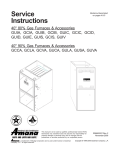
®
Heating ¡ Air Conditioning
A higher standard of comfort
GUD-X
High Efficiency
Gas Fired
Warm Air Furnace
Model Number
Input
(BTUH)
Output
(BTUH)
Temp.
Rise
Number
Range, °F
of
Burners
AFUE
Specification Sheet
Affix this Specification Sheet, Installation Instructions and
User Information manual adjacent to the unit.
Blower
Minimum
Circuit
Ampacity1
Maximum
Overcurrent
Protection2
D" x W" HP
Pressure
AC Tons @ Switch Setting
.5 ESP
(Inches W.C.)3
Speeds
Shipping
Weight
(lbs)
GUD045X30B
45,000
43,000
95.6
25-55
2
11.3
15
10X8
1/3
3
2.0-3.0
-1.38
GUD070X30B
70,000
65,700
93.8
35-65
3
10.3
15
10X8
1/3
4
2.0-3.0
-1.38
194
GUD070X40B
70,000
65,700
93.8
35-65
3
14.1
15
10X10
3/4
4
3.0-4.0
-1.38
194
GUD090X35B
90,000
84,300
93.7
45-75
4
10.1
15
10X8
1/2
4
2.0-3.5
-1.57
216
GUD090X50B
90,000
85,100
94.6
35-65
4
15.1
20
10X10
3/4
4
3.5-5.0
-1.57
216
GUD115X50B
115,000 107,600
93.6
35-65
5
15.1
20
10X10
3/4
4
3.5-5.0
-1.38
231
1
2
3
Minimum Circuit Ampacity = (Circulating Blower Amps x 1.25) + I.D. Blower Amps
Maximum Overcurrent Protection refers to maximum recommended fuse or circuit breaker size.
As shipped for installations below 4,000 feet.
158
WARNING
To avoid death, personal injury or
property damage due to fire, do not
exceed maximum recommended
fuse or circuit breaker size.
Dimensions
Left Side View
3/4
Front View
28-1/8
28
20-1/8
A
2-3/8
B
3/4
3/4
6-5/8
Right Side View
Top View
Gas
Supply
Electrical Hole
Hole-Low
1-5/8
Voltage
Supply
4-3/4
48
Electrical
Hole-Line
Voltage 5-7/8
Electrical
Hole-Low
Voltage
38-3/4
40
6-5/8
23
Supply
Combustion
Air Inlet
Gas Supply Hole
Electrical Hole
Line Voltage
Gas
Supply
Hole
Flue Outlet
4-1/4
1-3/4
2
4-3/8
38-1/4
38-3/4
1-1/8
14
Side KO
28-3/4
1-5/8
1-5/8
23
Bottom KO
Due to continuous engineering design and development, the above
information is subject to change without notice.
January 1998
2-1/2
C
E
16-1/2
Condensate Drain
(Left or Right Side)
D
Bottom KO
Size
45
70
90
115
Amana
Fayetteville, TN 37334
A
16-1/2
20-1/2
24-1/2
24-1/2
B
15
19
23
23
C
7
11
10-1/2
12-1/2
D
10-1/2
14-1/2
18-1/2
18-1/2
E
2-5/8
2-5/8
4-5/8
2-5/8
All dimensions are in inches.
11134620
Model (Htg.
Speed As
Shipped)
GUD045X30B
(MED)
GUD070X30B
(HIGH)
GUD070X40B
(MED-LOW)
GUD090X35B
(MED)
GUD090X50B
(MED)
GUD115X50B
(HIGH)
Motor
Speed
HIGH
MED
LOW
HIGH
MED
MED-LO
LOW
HIGH
MED
MED-LO
LOW
HIGH
MED
MED-LO
LOW
HIGH
MED
MED-LO
LOW
HIGH
MED
MED-LO
LOW
Tons AC
at .5"
ESP
3.0
2.5
2.0
3.0
2.5
2.0
1.5
4.0
3.5
3.5
3.0
4.0
3.5
3.0
2.5
5.0
4.5
4.0
3.5
5.0
4.5
4.0
3.5
0.1
CFM RISE
1381 28
1173 33
908
42
1458 41
1270 47
1019 59
782
----1861 ----1699 36
1519 40
1278 47
1664 47
1465 53
1089 71
850
----2271 ----1951 40
1724 45
1495 52
2358 42
1922 52
1699 58
1475 -----
External Static Pressure, Inches Water Column
0.2
0.3
0.4
0.5
CFM RISE CFM RISE CFM RISE CFM RISE
1319 29 1260 30 1197 32 1131 34
1142 34 1103 35 1055 36
998
38
901
43
884
43
855
45
815
47
1395 43 1334 45 1266 47 1188 50
1229 49 1178 51 1122 53 1060 56
1001 60
973
61
938
64
891
----778
----- 766
----- 746
----- 708
----1803 ----- 1714 35 1647 37 1561 39
1643 37 1577 38 1512 40 1431 42
1482 41 1439 42 1386 44 1316 46
1277 47 1268 48 1227 49 1164 52
1599 49 1532 51 1465 53 1395 56
1439 54 1395 56 1345 58 1288 60
1108 70 1106 70 1092 71 1059 73
845
----- 841
----- 834
----- 823
----2184 36 2094 37 2000 39 1914 41
1889 41 1837 42 1770 44 1701 46
1695 46 1647 47 1598 49 1534 51
1474 53 1448 54 1407 55 1356 57
2228 44 2094 47 1997 49 1896 52
1869 52 1810 55 1743 57 1688 59
1672 59 1630 61 1583 63 1526 65
1462 ----- 1441 ----- 1414 ----- 1369 -----
0.6
CFM
1055
931
760
1111
986
831
659
1457
1312
1196
1069
1312
1218
1021
801
1810
1598
1412
1289
1800
1583
1454
1317
0.7
CFM
960
848
688
1015
898
750
590
1278
1164
1063
937
1234
1145
961
759
1701
1489
1362
1196
1680
1488
1369
1232
0.8
CFM
847
736
602
895
778
649
501
1063
977
903
839
1150
1048
883
688
1552
1353
1236
1036
1552
1364
1248
1067
NOTES:
•
CFM information in the above table is with high velocity, permanent filter(s) as shipped with the furnace. If the furnace is shipped with two
side return filters, this table assumes both filters are used.
•
All furnaces ship as high speed for cooling. Installer must adjust blower speed as needed.
•
For most jobs, about 400 CFM per ton when cooling is desirable.
•
This chart is for furnaces installed at 0 - 4000 feet. At higher altitudes, a properly derated unit will have the same temperature rise at a particular
CFM, while the ESP at that CFM will be lower.
•
The shaded area (
)indicates ranges in excess of maximum external static pressure allowable when heating. For satisfactory operation,
external static pressure should not exceed 0.5” W.C. The data for 0.6” W.C. to 0.8” W.C. is shown for air conditioning purposes only.
•
The dashed (-----) areas indicate a temperature rise not recommended for this model.
•
The installation must be adjusted to obtain a temperature rise within the range listed on the furnace nameplate.
2
5. Drain connections must conform to local codes.
Accessibility Clearances (Minimum)
6. Installer must supply the following gas line fittings
according to which entrance is used:
WARNING
Top
To avoid death, personal injury or property
damage due to fire, clearances to combustible surfaces listed as below must be
observed.
Left
Right
Two 90° Elbows
One Close Nipple
One 90° Elbow
One 90° Elbow
One 45° Elbow
One Close Nipple
36 inches front clearance is required for servicing or cleaning.
NOTE: In all cases, accessibility clearance must take
precedence over clearances from the enclosure where
accessibility clearances are greater.
Flame Sensor
Flame sensor output is 1 to 4 microamps at 115 volts.
Filters
CLEARANCES TO COMBUSTIBLE SURFACES
GUD_ MODEL FURNACES (Inches)
FRONT
3
TOP
1
RIGHT
1
FLUE
0
LEFT
1
FLOOR
REAR
0
Side Return Filters
Minimum Recommended Size
Size_Air Flow Disposable*
Permanent*
C
045_30
1 - 24x24 (576) 1 - 16x25 (280)
070_30
1 - 24x24 (576) 1 - 16x25 (280)
High Altitude Installations
070_40
2 - 16x25 (768) 1 - 16x25 (372)
For installations above 4000 feet, please refer to your
Amana distributor for required kit(s).
090_35
2 - 14x25 (692) 1 - 16x25 (342)
090_50
2 - 20x25 (960) 2 - 16x25 (465)
115_50
2 - 20x25 (960) 2 - 16x25 (465)
----
----
C = If placed on combustible floor, floor MUST be wood only.
Gas
Altitude
Kit
Natural 0-4000 Ft. None
Propane 0-4500 Ft. LPTK09
Orifice
#43
#55
Manifold
Pressure
3.5" W.C.
10.0" W.C.
*
Bottom Return Filter Sizes
Model Filter Size (Inches) Type
NOTE: In Canada, gas furnaces are certified to 4,500 feet
only.
IMPORTANT NOTES:
1. All furnaces have a redundant gas valve and blower
door interlock switch.
45
14 x 25 x 1
P
70
16 x 25 x 1*
P
90
20 x 25 x 1
P
115
20 x 25 x 1
P
P = Permanent
* As Shipped With Furnace
2. All furnaces are manufactured for use on 115 VAC, 60
Hz, single phase electrical supply.
3. IMPORTANT: While the data is presented as a guide,
it is very important to properly size fuses and wires and
make electrical connections in accordance with the
National Electrical Code and/or all existing local codes.
Quantity - Inches (Total Minimum Surface Area in Square Inches)
Permanent filter sizes are as shipped with furnace. The minimum
permanent filter size area is based on allowable face velocity of 620
feet per minute.
The figure below shows how the filter is retained over the
bottom return air opening.
Filter Retainer
4. Performance figures are based on Department of Energy information and requirements under continuous
operating conditions. Performance will vary with weather
conditions and use.
Filter
Furnace Bottom
Filter Retainer
3
WARNING
To prevent death, personal injury or property damage due to electrical shock, disconnect electrical power to this furnace
before servicing or performing maintenance.
Y
W
R
THERMOSTAT
CONNECTIONS
PRESSURE SWITCH (PS)
6
PRIMARY
ROLLOUT
LIMIT (RL)
CONTROL
NC
G
C
RD-44
TERMINAL ORDER REARRANGED FOR CLARITY
**
C 2
BR-21
M 1
GY-47
BK-6
BK-1
DOOR SWITCH (CLOSED
WHEN DOOR IN PLACE)
GND
N
IGNITOR
WARNING:DISCONNECT POWER BEFOREPRIMARY
RL
SERVICING.WIRING TO UNIT MUST BE
PROPERLY POLARIZED AND GROUNDED.
115V
FIELD
CONNECT
WH
N
GND
FACTORY WIRED BLOWER MOTOR TO CONTROL CONNECTIONS
FURNACE MODEL
* MANUFACTURER'S VARIABLE LETTER
GUX: 045X30*
GUC: 070X40*
GUC: 045X30*
GUD: 045X30*
GUX: 070X40*
GUC: 090X50*
GUD: 070X40*
GUX: 070X30*,090X50*
GUD: 090X35*,090X50*
GUX: 090X35*,115X50*
GUC: 070X30*,115X50*
090X35*
GUD: 070X30*,115X50*
* HEATING BLOWER SPEED
** COOLING
SPEED
MOTOR TO "HEAT"
MOTOR
SPEEDS
LOW
LOW
RD-24
RD-24
3
4
MED
BU-23
3
MED LOW
OR-29
4
MED
BU-23
4
HI
BK-26
GY-47
WARNING:DISCONNECT POWER
BEFORE SERVICING.WIRING TO
UNIT MUST BE PROPERLY
POLARIZED AND GROUNDED.
ELECTRICAL BOX
4
BLOWER SPEED
SEE
INSTALLATION
INSTRUCTIONS
TO DETERMINE
PROPER
COOLING
BLOWER SPEED.
LOW VOLTAGE
LOW VOLTAGE FIELD
HI VOLTAGE
HI VOLTAGE FIELD
G
6
3
OR-3
BU
-36
11
8
5
2
10
7
4
1
C
BR-21
BU-25
YL-11
GY
-25
GN
RD-44
OR-3
COLOR CODE
YL YELLOW
OR ORANGE
VT VIOLET
GN GREEN
BK BLACK
BR BROWN
WH WHITE
BU BLUE
GY GRAY
RD RED
R
9
LINE
TRANSFORMER
LOAD
L1
W
12
HLO
L1
DOOR
SWITCH
Y
FP
NO
THERMOSTAT
CONNECTIONS
115V FIELD
CONNECT
HUMIDIFIER
WH-2
BK-3
C
TH
ACB
BK-1
IGNITOR
RO1
CAP
WH23
VT
-55
BK
6
BK-6
TR
4
CB
RD-22
WH
COMBUSTION
BLOWER
(CB)
GV
MV GND HLI
BU-36
PS
FLAME SENSOR
RO2
WH-33
FS
LE
AN
MS
EO
R
NEUTRAL 120VAC
C
NC
RD
-22
GN
C L X E H
I I F A U
R N M C M
E R
PS
BU-25
MV
BU-15
NO
VT
-55
OR-16
LIMIT
CONTROL
I I
NG
DN
VT-14
HOT 120VAC
P 3
24 V
L
I
M
I
T
*
WH
GAS
VALVE
(GV)
120 V
TRANSFORMER
**
X E H
F A U
M C M
R
P
A NI
GI NR R
REGF NNE 0 0
K UNPDDU1 2
5
L
I
N
E
P
A
R
K
CAPACITOR
(CAP)
P
A
R
K
H
E
A
T
YL
-11
#26 BK (HI)
#23 BU (MED)
#29 OR (MED LOW)
#24 RD (LOW)
P
A
R
K
C
HNHNHHN
HH
O
O E O E O O E T T P L L MMO
T UT UT T URHS I OV V L
*
RD-44
L
I
N
E
AIR
CIRCULATION
BLOWER
(ACB)
CIRCULATOR BLOWER
C
I
R
5
BR
H
E
A
T
X X
F F
MM
RR
BR
NO
OR
-16
C
O
O
L
EEHHL
AAUUI
C C M MN
E
115V FIELD
CONNECT
ELECTRONIC
AIR CLEANER
COM
GY-25
VT
-14
RD-44
IMPORTANT:
READ BEFORE OPERATING OR SERVICING THIS UNIT.
1. SET HEAT ANTICIPATOR ON ROOM THERMOSTAT AT 0.7 AMPS.
2. AMANA SPECIFIED REPLACEMENT PARTS MUST BE USED WHEN SERVICING.
3. IF ANY OF THE ORIGINAL WIRE AS SUPPLIED WITH THE FURNACE MUST BE
REPLACED, IT MUST BE REPLACED WITH WIRING MATERIAL HAVING A TEMPERATURE RATING
OF AT LEAST 105C. USE COPPER CONDUCTORS ONLY.
4. UNUSED BLOWER MOTOR LEADS MUST BE PLACED ON "PARK" TERMINALS OF CONTROL OR TAPED.
5 IF HEATING AND COOLING BLOWER SPEEDS ARE NOT THE SAME DISCARD JUMPER BEFORE
CONNECTING BLOWER LEADS.
6 DIAGNOSTIC LIGHT:STEADY=REPLACE CONTROL;1 FLASH=LOCKOUT;2 FLASHES=PS STUCK CLOSED;
3 FLASHES=PS STUCK OPEN;4 FLASHES=OPEN HIGH LIMIT SWITCH;
5 FLASHES=OPEN ROLLOUT CONTROL;
CONTINUOUS FLASHING=FLAME-NO CALL FOR HEAT
11165501 REV. 0