1
S
Agilent 81130A 400/660MHz Pulse/Data Generator
Reference Guide
S1
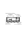
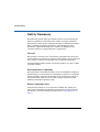
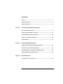
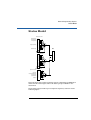
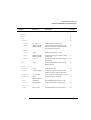
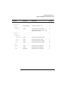
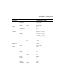
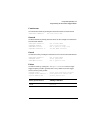
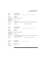
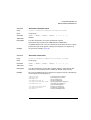
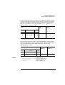
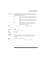
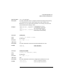
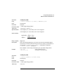
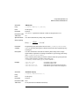
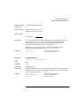
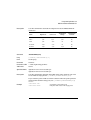
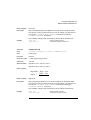
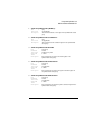
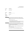
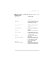
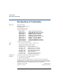
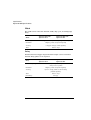
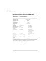
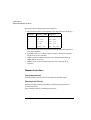
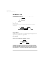
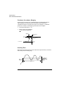
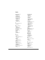
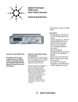
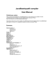
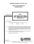
Front Panel Display and Softkeys
Mode / Parameter Area
Channel 1
Column
Use the CURSOR keys to
move the entry focus to a
mode, parameter format,
or
parameter value
ON
OFF
Delay
DtyCyc
1
Modify / Enter Area
Use the KNOB to select a
mode or modify parameters
and formats
Channel 2
Column
Freq 50.00MHz
0ps Delay
50.0% Width
Press ENTER or a UNIT key to
confirm parameter changes
OFF
OFF
2
0ps
100.0ns
Entry
Focus
MODIFY
50.0
%
MODE/TRG
TIMING
LEVELS
PATTERN
GRAPH
MORE
Press a SOFTKEY to access
the required entry screen
Screen Selection Area
Press MORE key to access
the additional screen menus:
LIMITS
TRG-LEV
MEMCARD
CONFIG
Reference Guide
Agilent 81130A 400/660 MHz
Pulse/Data Generator
Part No. 81130-91021
Printed in Germany March 2000
Edition 1.0, E0300
Notice
Notice
Copyright
1998 Agilent Technologies 1998, 2000. All rights reserved.
No part of this manual may be reproduced in any form or by any means
(including electronic storage and retrieval or translation into a foreign
language) without prior agreement and written consent from Agilent
Technologies Inc. as governed by United States and international
copyright laws.
Notice
The material contained in this document is subject to change without
notice. Agilent Technologies makes no warranty of any kind with regard
to this material, including, but not limited to, the implied warranties of
merchantability and fitness for a particular purpose. Agilent
Technologies shall not be liable for errors contained herein or for
incidental or consequential damages in connection with the furnishing,
performance, or use of this material.
Warranty
This Agilent Technologies product has a warranty against defects in
material and workmanship for a period of three years from date of
shipment. During the warranty period, Agilent Technologies will, at its
option, either repair or replace products that prove to be defective. For
warranty service or repair, this product must be returned to a service
facility designated by Agilent Technologies. The Buyer shall pay Agilent
Technologies round-trip travel expenses. For products returned to
Agilent Technologies for warranty service, the Buyer shall prepay
shipping charges to Agilent Technologies and Agilent Technologies shall
pay shipping charges to return the product to the Buyer. However, the
Buyer shall pay all shipping charges, duties and taxes for products
returned to Agilent Technologies from another country.
4
Notice
Agilent Technologies warrants that its software and firmware designated
by Agilent Technologies for use with an instrument will execute its
programming instructions when properly installed on that instrument.
Agilent Technologies does not warrant that the operation of the
instrument software, or firmware, will be uninterrupted or error free.
Limitation of Warranty
The foregoing warranty shall not apply to defects resulting from
improper or inadequate maintenance by the Buyer, Buyer-supplied
software or interfacing, unauthorized modification or misuse, operation
outside of the environmental specifications for the product, or improper
site preparation or maintenance. No other warranty is expressed or
implied. Agilent Technologies specifically disclaims the implied
warranties of merchantability and fitness for a particular purpose.
Exclusive Remedies
The remedies supplied are the Buyer's sole and exclusive remedies.
Agilent Technologies shall not be liable for any direct, indirect, special,
incidental, or consequential damages, whether based on contract, tort or
any other legal theory.
Certification
Agilent Technologies certifies that this product met its published
specifications at the time of shipment. Agilent Technologies further
certifies that its calibration measurements are traceable to the United
States Institute of Standards and Technology, to the extent allowed by
the Institute's calibrating facility, and to the calibration facilities of other
International Standards Organization members.
Services and Support
Any adjustment, maintenance, or repair of this product must be
performed by qualified personnel. Contact your customer engineer
through your local Agilent Technologies Service Center. You can find a
list of local service representatives on the Web at:
http://www.agilent.com/Service/English/index.html
5
Safety Summary
Safety Summary
The following general safety precautions must be observed during all
phases of operation of this instrument. Failure to comply with these
precautions or with specific warnings elsewhere in this manual violates
safety standards of design, manufacture, and intended use of the
instrument. Agilent Technologies Inc. assumes no liability for the
customer's failure to comply with these requirements.
General
This product is a Safety Class 1 instrument (provided with a protective
earth terminal). The protective features of this product may be impaired
if it is used in a manner not specified in the operation instructions.
All Light Emitting Diodes (LEDs) used in this product are Class 1 LEDs
as per IEC 60825-1.
Environmental Conditions
This instrument is intended for indoor use in an installation category II,
pollution degree 2 environment. It is designed to operate at a maximum
relative humidity of 95% and at altitudes of up to 2000 meters. Refer to
the specifications tables for the ac mains voltage requirements and
ambient operating temperature range.
Before Applying Power
Verify that the product is set to match the available line voltage, the
correct fuse is installed, and all safety precautions are taken. Note the
instrument's external markings described under Safety Symbols on
page 8.
6
Safety Summary
Ground the Instrument
To minimize shock hazard, the instrument chassis and cover must be
connected to an electrical protective earth ground. The instrument must
be connected to the ac power mains through a grounded power cable,
with the ground wire firmly connected to an electrical ground (safety
ground) at the power outlet. Any interruption of the protective
(grounding) conductor or disconnection of the protective earth terminal
will cause a potential shock hazard that could result in personal injury.
Fuses
Only fuses with the required rated current, voltage, and specified type
(normal blow, time delay, etc.) should be used. Do not use repaired fuses
or short-circuited fuse holders. To do so could cause a shock or fire
hazard.
Do Not Operate in an Explosive Atmosphere
Do not operate the instrument in the presence of flammable gases or
fumes.
Do Not Remove the Instrument Cover
Operating personnel must not remove instrument covers. Component
replacement and internal adjustments must be made only by qualified
service personnel.
Instruments that appear damaged or defective should be made
inoperative and secured against unintended operation until they can be
repaired by qualified service personnel.
7
Safety Summary
Safety Symbols
Caution (refer to accompanying documents)
Protective earth (ground) terminal
In the manuals:
WA RN I NG
The WARNING sign denotes a hazard. It calls attention to a
procedure, practice, or the like, which, if not correctly performed
or adhered to, could result in personal injury. Do not proceed
beyond a WARNING sign until the indicated conditions are fully
understood and met.
CA UT IO N
The CAUTION sign denotes a hazard. It calls attention to an operating
procedure, or the like, which, if not correctly performed or adhered to,
could result in damage to or destruction of part or all of the product. Do
not proceed beyond a CAUTION sign until the indicated conditions are
fully understood and met.
8
About this Book
About this Book
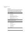
This guide provides reference information primarily for programming the
Agilent 81130A via remote control.
Chapter 1 General Programming Aspects on page 13 gives general
hints for programming instruments like the Agilent 81130A using SCPI
commands.
Chapter 2 Programming Reference on page 25 provides detailed
information on the SCPI commands supported by the instrument.
Chapter 3 Specifications on page 95 lists the instruments technical
specifications and provides exact definitions for the instruments
parameters.
For an introduction and information on the Agilent 81130As user
interface, please refer to the Quick Start Guide, p/n 81130-91020.
9
About this Book
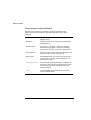
Conventions Used in this Book
This book uses certain conventions to indicate elements of the
Agilent 81130As user interface. The following table shows some
examples:
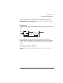
Softkeys
Press the MODE/TRG softkey to access the Mode/
Trigger screen.
Hardkeys
Press the MORE key to switch to the alternative
softkey layout.
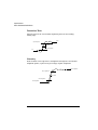
Alternate Keys
Press SHIFT + 0 (ON/OFF1) to switch on output1.
The alternate key labelwhich is selected by
pressing the SHIFT keyis given in parentheses.
Screen Quotes
Move the entry focus down to PULSE-PERIOD and
turn the knob to select INTERNAL PLL.
Entry Focus
The highlight field, that can be moved with the
cursor keys, to change modes, parameters, or
parameter formats.
:VOLTage:HIGH 3V Full command for programming a 3 V high level.
The upper case letters represent the short form
of the command, which results in faster programming times.
*RST
10
Common IEEE 488 command, to reset instrument to default status.
Contents
Notice ......................................................................................... 4
Safety Summary ......................................................................... 6
About this Book ......................................................................... 9
Chapter 1
General Programming Aspects
The GP-IB Interface Bus ......................................................... 14
Agilent 81130A Remote Control ............................................ 15
Programming Recommendations ............................................ 16
Common Command Summary ................................................. 18
Status Model ............................................................................ 19
Chapter 2
Programming Reference
Agilent 81130A SCPI Command Summary ............................ 26
Default Values, Standard Settings ......................................... 34
Programming the Instrument Trigger Modes ........................ 38
SCPI Instrument Command List ............................................ 42
Chapter 3
Specifications
Declaration of Conformity ...................................................... 96
xi
Contents
Agilent 81130A Specifications ............................................... 97
General ................................................................................................... 97
Timing Specifications ........................................................................... 99
Main Output Level Specifications ..................................................... 102
External Input, External Clock/PLL Reference Input .................... 103
Trigger Modes ...................................................................................... 105
Output Modes ...................................................................................... 106
Human Interface .................................................................................. 108
Memory ................................................................................................. 109
Remote Control ................................................................................... 109
Pulse Parameter Definitions ................................................ 111
xii
1
1General Programming
Aspects
This chapter provides general information on writing GP-IB/SCPI
programs for instruments like the Agilent 81130A.
Detailed information on programming the Agilent 81130A can be found in
Chapter 2 Programming Reference on page 25.
13
General Programming Aspects
The GP-IB Interface Bus
The GP-IB Interface Bus
The GP Interface Bus is the interface used for communication between a
controller and an external device, such as the Agilent 81130A. The GP-IB
conforms to IEEE standard 488-1987, ANSI standard MC 1.1, and IEC
recommendation 625-1.
If you are not familiar with the GP-IB, please refer to the following
books:
The Institute of Electrical and Electronic Engineers: IEEE Standard
488.1-1987, IEEE Standard Digital Interface for Programmable
Instrumentation.
The Institute of Electrical and Electronic Engineers: IEEE Standard
488.2-1987, IEEE Standard Codes, Formats, and Common
Commands for Use with IEEE Standard 488.1-1987.
14
General Programming Aspects
Agilent 81130A Remote Control
Agilent 81130A Remote Control
GP-IB Address
You can only set the GP-IB address from the front panel of the instrument
(refer to the Quick Start Guide).
The default GP-IB address is 10.
Modes of
Operation
The Agilent 81130A has two modes of operation:
Local
The instrument is operated using the front panel keys.
Remote
After receiving the first command or query via the GP-IB, the
instrument is put into remote state. The front panel is locked.
To return to local operating mode, press SHIFT (LOCAL).
15
General Programming Aspects
Programming Recommendations
Programming Recommendations
Here are some recommendations for programming the instrument:
Start programming from the default setting. The common command
for setting the default setting is:
*RST
Switch off the automatic update of the display to increase the
programming speed. The device command for switching off the
display is:
:DISPlay OFF
The SCPI standard defines a long and a short form of the commands.
For fast programming speed it is recommended to use the short
forms. The short forms of the commands are represented by upper
case letters. For example the short form of the command to set 100 ns
delay is:
:PULS:DEL 100NS
To improve programming speed it is also allowed to skip optional
subsystem command parts. Optional subsystem command parts are
depicted in square brackets, e.g.: set amplitude voltage of output 1:
[SOURce]:VOLTage[1][:LEVel][:IMMediate][:AMPLitude].
Sufficient to use: :VOLT 1.2V
For the commands to set the timing and level parameters, except of
period/frequency, you can explicitly specify the output to be
programmed (for compatibility reasons). If there is no output
specified, the commands will set the default output 1.
So, for setting a high level of 3 Volts for output 1 the commands are:
:VOLT:HIGH 3V
# sets high level of 3 V at out 1
:VOLT1:HIGH 3V
# sets high level of 3 V at out 1
16
General Programming Aspects
Programming Recommendations
It is recommended to test a new setting that will be programmed on
the instrument by setting it up manually.
Enable the outputs so that the instruments error check system is on
and possible parameter conflicts are immediately displayed.
When you have found the correct setting, then use this to create the
program. In the program it is recommended to send the command for
enabling outputs (for example, :OUTPut ON) as the last command.
Selftest of the instrument can be invoked by the common command
*TST
If it is important to know whether the last command is completed,
then send the common command
*OPC?
17
General Programming Aspects
Common Command Summary
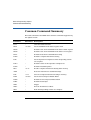
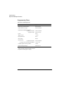
Common Command Summary
This table summarizes the IEEE 488.2 common commands supported by
the Agilent 81130A:
Command
Parameter Description
*CLS
Clear the status structure
*ESE
<0255>
Set the Standard Event Status register mask
*ESE?
Read the state of the Standard Event Status enable register
*ESR?
Read the state of the Standard Event Status event register
*IDN?
Read the Instrument's Identification string
*LRN?
Read the complete Instrument Setting
*OPC
Set the Operation Complete bit when all pending actions
are complete
*OPC?
Read the status of the Operation Complete bit
*OPT?
Read the installed options
*RCL
<04>
Recall a complete Instrument Setting from memory
*RST
Reset the instrument to standard settings
*SAV
<14>
Save the complete Instrument Setting to memory
*SRE
<0255>
Set the Service Request Enable Mask
*SRE?
Read the Service Request Enable Mask
*STB?
Read the Status Byte
*TRG
Trigger
*TST?
Execute instruments selftest
*WAI
Wait until all pending actions are complete
18
General Programming Aspects
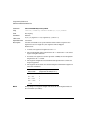
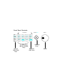
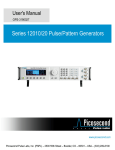
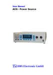
Status Model
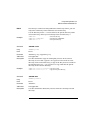
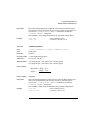
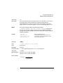
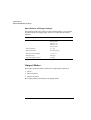
Status Model
QUESTIONABLE STATUS
Voltage Warning
Current Warning
Timing Warning
Frequency Warning
Pattern Warning
0
1
2
3
4
5
6
7
8
9
15
OPERation Status
(NOT USED)
0
1
2
3
4
5
6
7
8
9
Status
Byte
MAV
SRQ
0
1
2
3
4
5
6
7
15
Standard Event Status
Operation Complete
0
1
2
Query Error
Device Dependent Error
3
Execution Error
4
Command Error
5
6
Power On
7
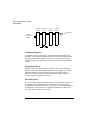
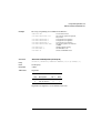
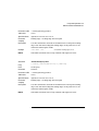
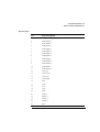
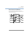
The instrument has a status reporting system conforming to IEEE 488.2
and SCPI. The above figure shows the status groups available in the
instrument.
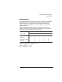
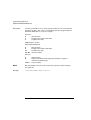
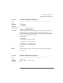
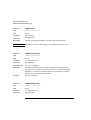
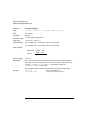
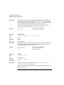
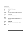
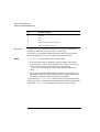
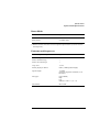
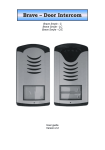
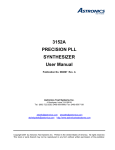
Each status group is made up of component registers, as shown in the
following figure.
19
General Programming Aspects
Status Model
Condition
Register
Transition
Filters
Event
Register
Enable
Register
OR
Hardware
and Firmware
condition
1
0
PTR
NTR
Summary Bit
1 Latched
0
Condition Register
A condition register contains the current status of the hardware and
firmware. It is continuously updated and is not latched or buffered. You
can only read condition registers. If there is no command to read the
condition register of a particular status group, then it is simply invisible
to you.
Transition Filters
Transition filters are used to detect changes of state in the condition
register and set the corresponding bit in the event register. You can set
transition filter bits to detect positive transitions (PTR), negative
transitions (NTR) or both. Transition filters are therefore read/write
registers. They are unaffected by *CLS.
Event Register
An event register latches transition events from the condition register as
specified by the transition filters or records status events. Querying
(reading) the event register clears it, as does the *CLS command. There is
no buffering, so while a bit is set, subsequent transition events are not
recorded. Event registers are read only.
20
General Programming Aspects
Status Model
Enable Register
The enable register defines which bits in an event register are included in
the logical OR into the summary bit. The enable register is logically
ANDed with the event register and the resulting bits ORed into the
summary bit. Enable registers are read/write, and are not affected by
*CLS or querying.
Although all status groups have all of these registers, not all status
groups actually use all of the registers. The following table summarizes
the registers used in the instrument status groups.
Registers in Group
1
2
3
4
5
Status Group
CONDition
NTR
PTR
EVENt
ENABLe
QUEStionable
√
√
√
√
√
OPERation1
x
x
x
x
x
Standard Event Status
x
x
x
√2
√3
Status Byte
x
x
x
√4
√5
Present, but not used. COND and EVEN always 0.
Use *ESR? to query.
Use *ESE to set, *ESE? to query
Use *STB? to query
Use *SRE to set, *SRE? to query
21
General Programming Aspects
Status Model
Status Byte
The status byte summarizes the information from all other status groups.
The summary bit for the status byte actually appears in bit 6 (RQS) of the
status byte. When RQS is set it generates an SRQ interrupt to the
controller indicating that at least one instrument on the bus requires
attention. You can read the status byte using a serial poll or *STB?
Bit
Description
0
Unused, always 0
1
Unused, always 0
2
Unused, always 0
3
QUESTionable Status Summary Bit
4
MAVMessage AVailable in output buffer
5
Standard Event Status summary bit
6
RQS; ReQuest Service
7
OPERation Status summary Bit, unused
Standard Event Status Group
Bit
Description
0
Operation Complete, set by *OPC
1
Unused, always 0
2
Query Error
3
Device Dependent Error
4
Execution Error
5
Command Error
6
Unused, always 0
7
Power On
22
General Programming Aspects
Status Model
OPERation Status Group
This Status Group is not used in the instrument.
Bit
Description
0
Unused, always 0
1
Unused, always 0
2
Unused, always 0
3
Unused, always 0
4
Unused, always 0
5
Unused, always 0
6
Unused, always 0
7
Unused, always 0
8
Unused, always 0
9
Unused, always 0
10
Unused, always 0
11
Unused, always 0
12
Unused, always 0
13
Unused, always 0
14
Unused, always 0
15
Always 0
23
General Programming Aspects
Status Model
QUEStionable Status Group
Bit
QUEStionable
0
Voltage warning
1
Current warning
2
Time warning
3
Unused, always 0
4
Unused, always 0
5
Frequency warning
6
Unused, always 0
7
Unused, always 0
8
Unused, always 0
9
Pattern warning
10
Unused, always 0
11
Unused, always 0
12
Unused, always
13
Unused, always 0
14
Unused, always 0
15
Always 0
The QUEStionable Status group is used to report warning conditions
amongst the voltage, current, pulse timing, frequency and pattern
parameters. Warnings occur when a parameter, although not outside its
maximum limits, could be causing an invalid signal at the output because
of the actual settings and uncertainties of related parameters.
24
2
2Programming Reference
This chapter provides reference information on the following topics:
Agilent 81130A SCPI Command Summary on page 26
Default Values, Standard Settings on page 34
Programming the Instrument Trigger Modes on page 38
SCPI Instrument Command List on page 42
For general programming information, please refer to Chapter 1
General Programming Aspects on page 13.
25
Programming Reference
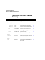
Agilent 81130A SCPI Command Summary
Agilent 81130A SCPI Command
Summary
Command
Parameter
Description
see page
(Trigger mode and source)
:ARM
[:SEQuence[1] | :STARt]
[:LAYer[1]]
:LEVel
[:THReshold]
<value>
Set/read threshold level at EXT INPUT
43
:TERMination
<value>
Set/read the termination voltage at EXT INPUT
43
:MODE
GATed | STARted
Set/read the trigger mode, if the source is
not IMMediate
43
:SENSe
POSitive | NEGative
Set/read trigger on edge or gate on level
44
:SOURce
EXT1| IMM | MAN
Set/read trigger source
(EXT INPUT| IMMediate | MAN key)
44
ON | OFF | 1 | 0
Starts or stops the instrument, if the arming
source is not IMMediate
45
OFF|DIGital
Set/read addition of channels of channels 1
& 2 at output 1
45
:INITiate
:CONTinuous
:CHANnel
:MATH
26
Programming Reference
Agilent 81130A SCPI Command Summary
Command
Parameter
Description
see page
:DIGital
[:STIMulus]
:PATTern
48
:LOOP
45
46
:INFinite
[:STATe]
ON | OFF | 1 | 0
Enables/Disables the infinite loop
:STARt
SEGM1 | SEGM2 |
SEGM3 | SEGM4
Set/read the start of the infinite loop (the
segment to restart the output after the last
bit of the last used segment)
[:COUNt]
<value>
Set/read the segment loop count
:STARt
SEGM1 | SEGM2 |
SEGM3 | SEGM4
Set/read the start segment for the counted
segment loop
47
:LENGth
1|2|3|4
Set/read the number of segments within the
segment loop
48
<base>
Set/read the PRBS base (the same for all
PRBS segments!)
48
47
[:LEVel[1]]
:PRBS
:SEGMent[1|2|3|4]
:DATA[1|2]
<data>
Set/read pattern data
49
:LENGth
<segment-length>
Set/read the length of the segment (if the
length is increased, 0 bits are appended)
52
:PRESet[1|2]
[<n>,]<length>
Set preset pattern with frequency CLOCK ÷ n
53
:TYPE[1|2]
DATA|
PRBS|HIGH|LOW
Set/read the type of the segment
53
OFF|ON|0|1
Switch PATTERN pulse-mode on or off
OFF|ON|ONCE
Update the hardware with pattern data
54
RZ | R1 | NRZ
Set/read data format of output channel
54
[:STATe]
:UPDate
:SIGNal[1|2]
:FORMat
27
Programming Reference
Agilent 81130A SCPI Command Summary
Command
Parameter
Description
see page
55
:DISPlay
[:WINDow]
ON|OFF|1|0
Set/read frontpanel display state
:CATalog?
[A:]
Read directory of memory card
56
:CDIRectory
[<name>]
Change directory on memory card
56
:COPY
<source>[,A:],<dest>
[,A: ]
Copy a file on memory card
57
:DELete
<name>[,A:]
Delete a file from memory card
57
:INITialize
[A:[DOS]]
Initialize memory card to DOS format
58
<n>,<name>
Load file from memory card to memory n
58
<n>,<name>
Store memory n to memory card
58
[:STATe]
:MMEMory
:LOAD
:STATe
:STORe
:STATe
59
:OUTPut[1|2]
[:NORMal]
OFF|ON|1|0
[:STATe]
Set/read normal output state
59
:COMPlement
OFF|ON|1|0
[:STATe]
28
Set/read complement output state
Programming Reference
Agilent 81130A SCPI Command Summary
Command
Parameter
Description
see page
[:SOURce]
:CORRection[1|2]
60
:EDELay
[:TIMe]
<value>
Set/read channel delay deskew
The CURRent and VOLTage subsystem cannot be used at the same time. Use the :HOLD
command to select between them.
:CURRent[1|2]
60
[:LEVel]
[:IMMediate]
[:AMPLitude]
<value>
Set/read channel amplitude current
:OFFSet
<value>
Set/read channel offset current
61
:HIGH
<value>
Set/read channel high-level current
62
:LOW
<value>
Set/read channel low-level current
63
:HIGH
<value>
Set/read maximum current limits
63
:LOW
<value>
Set/read minimum current limits
64
:STATe
ON|OFF|1|0
Enable/Disable the current limits
64
<value>
Set/read frequency of pulses
65
ONCE
Do a frequency measurement at CLK IN
66
VOLT|CURR
Switch between VOLTage and CURRent
command subtrees
66
:LIMit
:FREQency
[:CW]
[:FIXed]
:AUTO
:HOLD[1|2]
29
Programming Reference
Agilent 81130A SCPI Command Summary
Command
Parameter
Description
see page
[:SOURce]
:PHASe[1|2]
<value>
[:ADJust]
<value>
Set/read channel phase
:DCYCle[1|2]
<value>
Set/read channel dutycycle
67
:DELay[1|2]
<value>
Set/read channel delay (to leading edge)
68
:HOLD
TIME|PRATio
Hold absolute delay|delay as period fixed
with varying frequency
69
:UNIT
S|SEC|PCT|DEG|
RAD
Set/read delay units
70
:HOLD[1|2]
WIDTh | DCYCle |
TDELay
Hold Width|Dutycycle|Trailing edge delay
fixed with varying frequency
70
:PERiod
<value>
Set/read pulse period
70
ONCE
Measure pulse period at CLK IN
71
<value>
Set/read trailing edge delay
72
67
:PULSe
:AUTO
:TDelay[1|2]
72
:TRANsition[1|2]
:UNIT
S|SEC|PCT
Set/read transition-time units
[:LEADing]
<value>
Set/read leading-edge transition
:TRAiling
<value>
Set/read trailing-edge transition
73
:MODE
CONTinuous | STARt
Set/read the mode of the trigger output signal generation (ignored if not in pattern
mode)
74
:POSition
1|2|3|4
Set/read the trigger output signal position
74
72
:TRIGger[1]
74
:VOLTage
[:LEVel]
[:IMMediate]
:WIDTh[1|2]
30
TTL | PECL | SYM |
ECLGND | ECLN2V
Set/read TRIGGER OUTput levels
<value>
Set/read channel pulse-width
75
Programming Reference
Agilent 81130A SCPI Command Summary
Command
Parameter
Description
see page
INTernal|EXTernal
Set/read PLL reference source
76
<value>
Set/read frequency of external PLL
reference. Value will be rounded to 1 MHz,
2 MHz, 5 MHz or 10 MHz.
76
[:SOURce]
:ROSCillator
:SOURce
:EXTernal
:FREQuency
77
:VOLTage[1|2]
[:LEVel]
[:IMMediate]
[:AMPLitude]
<value>
Set/read channel amplitude voltage
:OFFSet
<value>
Set/read channel offset voltage
77
:HIGH
<value>
Set/read channel high-level voltage
78
:LOW
<value>
Set/read channel low-level voltage
79
[:HIGH]
<value>
Set/read maximum voltage limit
80
:LOW
<value>
Set/read minimum voltage limit
80
:STATe
ON|OFF|1|0
Enable|Disable the voltage limits
81
:LIMit
31
Programming Reference
Agilent 81130A SCPI Command Summary
Command
Parameter
Description
see page
:STATus
81
:OPERation
[:EVENt]?
Read Operation event register
81
:CONDition
Read Operation condition register
81
:ENABle
Numeric
Set/Read Operation enable register
81
:NTRansition
Numeric
Set/Read Operation negative-transition
register
81
:PTRansition
Numeric
Set/Read positive-transition register
81
Clear and preset status groups
82
:PRESet
82
:QUEStionable
[:EVENt]?
Read Questionable event register
82
:CONDition?
Read Questionable condition register
82
:ENABle
Numeric
Set/Read Questionable enable register
82
:NTRansition
Numeric
Set/Read Questionable negative-transition
register
82
:PTRansition
Numeric
Set/Read Questionable positive-transition
register
32
Programming Reference
Agilent 81130A SCPI Command Summary
Command
Parameter
Description
see page
Read error queue
84
Simulate key press or read last key pressed
84
no function
87
:SYSTem
:ERRor?
:KEY
Numeric
:PRESet
87
:SECurity
[:STATe]
:SET
ON|OFF
Switch security on and off
Block data
Set/read complete instrument setting
88
Read SCPI compliance setting
88
:VERSion?
88
:WARNing
[:COUNt]?
Read number of active warnings
:STRing?
Read active warnings as concatenated string
89
:BUFFer?
Read maximum possible length of
concatenated string
89
(Pulse mode and period source)
:TRIGger
[:SEQuence [1]] | :STARt]
:COUNt
:PULSes[1|2]
<value>
Set/read number of triggered periods to be
generated per ARM event (BURST period)
89
<value>
Set/red the number of pulses within the triggered periods at OUTput 1 or OUTput 2
92
<value>
Set/read termination voltage level at CLK IN
92
IMM | INT[1] | EXT2
Set/read trigger source (Immediate | PLL |
CLK IN)
93
:LEVel
:TERMination
:SOURce
33
Programming Reference
Default Values, Standard Settings
Default Values, Standard Settings
Parameter
:ARM
*RST, Default Values
:LEVel
[:THReshold]
+1.0 V
:TERM
+0.0 V
:MODE
STARted
:SENSe
POS
:SOURce
IMM
:INITiate
:CONTinuous
ON
:CHANnel
:MATH
OFF
:DIGital
:PATTern:
OFF
:SIGNal
:DISPlay
:MMEMory
:LOOP:INFinite
ON
:LOOP:INFinite:STARt
SEGM1
:LOOP
1
:LOOP:STARt
SEGM1
:LOOP:LENGth
1
:PRBS
7
:SEGMent:DATA
see page 49
:SEGMent:LENGth
32, 0, 0, 0
:SEGMent:PRESet
not applicable
:SEGMent:TYPE
DATA
:UPDate
ON
:FORMat
RZ
ON
:CATatalog?
not applicable
:CDIRectory
not applicable
:COPY
not applicable
:DELete
not applicable
34
Programming Reference
Default Values, Standard Settings
Parameter
*RST, Default Values
:INITialize
not applicable
:LOAD
:STATe
not applicable
:STORe
:STATe
not applicable
:OUTPut
:CORRection
OFF
:COMPlement
OFF
:EDELay
0.0 s
20 mA (50 Ω into 50 Ω)
:CURRent
:OFFSet
0.0 µA (50 Ω into 50 Ω)
:HIGH
+10 mA (50 Ω into 50 Ω)
:LOW
10 mA (50 Ω into 50 Ω)
:LIMit
[:HIGH]
+10.0 mA
:LOW
10 mA
:STATe
OFF
:FREQuency
1.00 MHz
:AUTO
not applicable
:HOLD
VOLT
:PHAS
0.0
:PULSe
:DCYCle
10.0% (derived from Width and Period)
:DELay
0.00
:HOLD
TIME
:UNIT
SEC
:HOLD
WIDTh
:PERiod
1 µs
:AUTO
:TDELay
:TRANsition
not applicable
100 ns
:HOLD
TIME
:UNIT
SEC
35
Programming Reference
Default Values, Standard Settings
Parameter
*RST, Default Values
:TRIGger:
:ROSCillator
[:LEADING]
0.8 ns (Agilent 81131A) or not applicable
:TRAiling
0.8 ns (Agilent 81131A) or not applicable
:TRAiling:AUTO
ON
:MODE
STARt
:POSition
1
:VOLTage
TTL
:WIDTh
100 ns
:SOURce
INT
:EXTernal
:FREQuency
:VOLTage
1.00 V
:OFFSet
0.0 mV
:HIGH
500 mV
:LOW
500 mV
:LIMit
:STATus
:SYSTem
5 MHz
[HIGH]
+500 mV
:LOW
500 mV
:STATe
OFF
:OPERation
not applicable
:PRESet
not applicable
:QUESTionable
ON
:ERRor?
not applicable
:KEY
not applicable
:PRESet
not applicable
:SECurity
OFF
:SET
not applicable
:VERSion?
1992.0
:WARN?
36
[:COUNt]
not applicable
:STRing?
not applicable
:BUFFer?
not applicable
Programming Reference
Default Values, Standard Settings
Parameter
:TRIGger
*RST, Default Values
:COUNt
:LEVel
:SOURce
1
:PULSes
2
:TERMination
0.0 V
INT
37
Programming Reference
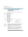
Programming the Instrument Trigger Modes
Programming the Instrument
Trigger Modes
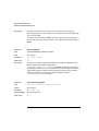
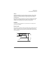
The following figure shows the instruments arming/triggering model:
Idle
*RST or power on
Trigger system
initiated(1)
no longer initiated(1)
Initiated
(still) initiated(1)
wait for Arm
completed # of Trigger
loops(2)
or
no longer initiated
ARM conditions
satisfied
wait for Trigger
Notes:
(1)
The instrument is always initiated in CONTINUOUS modes.
The instrument is automatically initiated in MANual started/gated modes.
(2)
1 in Pulses Mode (same as :TRIGger:COUNt)
:TRIGger:COUNt in Continuous/Gated Mode
Maximum of :TRIGger:COUNt:PULSes1 and :TRIGger:COUNt:PULSes2
in Started Burst mode
Trigger conditions
satisfied
For details of the
trigger count
command, refer to
“:TRIG:COUN” on
page 89.
Depends on sequence in Pattern Mode (may be infinite)
You program the comprehensive triggering capabilities of the instrument
using the SCPI :ARM and :TRIGger subsystems. Using these two
command subsystems you can program the operating modes of the
instrument which are set up using the MODE/TRG screen on the
frontpanel.
Use the :ARM subsystem to select the overall triggering mode of the
instrument (CONTINUOUS, STARTED, GATED), and the :TRIGger
subsystem to select the pulse period source, triggering and number of
pulse periods per :ARM event (BURST length). In pattern mode the
pattern length is the sum of each used segments length.
38
Programming Reference
Programming the Instrument Trigger Modes
Continuous
Set Continuous mode by arming the instrument from its internal PLL:
:ARM:SOURce IMMediate
Arm from internal PLL
Started
Set Started mode by arming the instrument on low to high level transition
from the EXT INPUT:
:ARM:SOURce EXTernal1
:ARM:MODE STARted
:ARM:SENSe POSitive
:ARM:LEVel:THReshold 1V
Arm from EXT INPUT
Start on the arm event
Arm on positive (high) level
Set EXT INPUT threshold
Gated
Set Gated mode by arming the instrument on levels from the EXT INPUT:
:ARM:SOURce EXTernal1
:ARM:MODE GATed
:ARM:SENSe POSitive
Arm from EXT INPUT
Select gated mode
Arm on positive level
Pulses
Set Pulses mode by setting the :TRIGger:COUNt to 1 so that a single
triggered pulse period is generated for every :ARM event. The trigger
source sets the pulse period:
:TRIGger:COUNt 1
:TRIGger:SOURce INTernal 1
:DIGital:PATTern OFF
Single pulse period per arm event
Pulse period from internal PLL
Disable pattern data.
Pulse period source
:TRIGger SOURce
internal PLL
CLK-IN
INTernal[1] or IMMediate
EXTernal2
39
Programming Reference
Programming the Instrument Trigger Modes
Burst
Set Burst mode by setting the :TRIGger:COUNt to the burst count
required. The trigger source sets the pulse period for the pulses within
the burst (See table in Pulses on page 39).
:TRIGger:COUNt 16
:TRIGger:SOURce INTernal1
:DIGital:PATTern OFF
Burst of 16 pulse periods
Pulse period from internal PLL.
Disable pattern data
Pattern
Set Pattern mode by setting the
:DIGital[STIMulus]:PATTern:SEGMent[1|2|3|4]:LENGth to the
required pattern length, and switching on digital pattern data. The trigger
source sets the pulse period for the data pulses (See table in Pulses on
page 39):
#Pattern length 512
:DIGital[:STIMulus]:PATTern:SEGMent1:LENGth
:DIGital[:STIMulus]:PATTern:SEGMent2:LENGth
:DIGital[:STIMulus]:PATTern:SEGMent3:LENGth
:DIGital[:STIMulus]:PATTern:SEGMent4:LENGth
512
0
0
0
#Disable counted segment loop
:DIGital[:STIMulus]:PATTern:LOOP:COUNt 1
#Jump back to start of segment 1 after the last bit of the last
segment (here: segment 1)
:DIGital[:STIMulus]:PATTern:LOOP:INFinite[:STATe] ON
:DIGital[:STIMulus]:PATTern:LOOP:INFinite:STARt SEGM1
:TRIGger:SOURce INTernal1
:DIGital:PATTern ON
:DIGital:SIGNal1:FORMat NRZ
:ARM:MODE STARted
:ARM:SOURce EXT1
40
Pulse period from internal PLL
Enable pattern data
Set OUTPUT 1 data to NRZ
Switch to started by EXT1
Programming Reference
Programming the Instrument Trigger Modes
Manually Starting and Gating
When starting and gating with the MAN key use the following commands:
STARTED
*TRG or :INITiate:CONTinuous ON to start the instrument
:INITiate:CONTinuous OFF to stop the instrument
GATED
:INITiate:CONTinuous ON to 'open the gate'
:INITiate:CONTinuous OFF to 'close the gate'
*TRG to gate for approx. 10ms
41
Programming Reference
SCPI Instrument Command List
SCPI Instrument Command List
The following reference sections list the instrument commands in
alphabetical order. In addition to a command description, the attributes
of each command are described under the following headings. Not all of
these attributes are applicable to all commands. The commands are
conform to the IEEE 488.2 SCPI standard.
Command
Shows the short form of the command.
Long
Shows the long form of the command.
Form
Most commands can be used in different forms:
Parameter
Set
The command can be used to program the instrument
Query
The command can be used to interrogate the instrument. Add a ? to
the command if necessary.
Event
The command performs a one-off action.
The type of parameter, if any, accepted by the command. The minimum
and maximum value of numeric parameters can be accessed by the
option MINimum or MAXimum.
Parameter Suffix The suffixes that may follow the parameter.
Functional
Coupling
Any other commands that are implicitly executed by the command.
Value Coupling
Any other parameter that is also changed by the command.
Range Coupling
Any other parameters whose valid ranges may be changed by the
command.
*RST value
The value/state following a *RST command.
Specified Limits
The specified limits of a parameter.
Absolute Limits
Some parameters can be programmed beyond their specified limits.
Example
Example programming statements.
42
Programming Reference
SCPI Instrument Command List
Command
:ARM:LEV[:THR]
Long
:ARM[:SEQuence[1] | :STARt][:LAYer]:LEVel[:THReshold]
Form
Set & Query
Parameter
Numeric
Parameter Suffix V with engineering prefixes.
*RST value
+1.0 V
Specified Limits
1.4 V to +3.7 V
Description
Use this command to program the triggering threshold of the EXT INPUT
connector.
Example
:ARM:LEV 2.5V
Command
:ARM:LEV:TERM
Long
:ARM[:SEQuence[1] | :STARt][:LAYer]:LEVel:TERMination
Form
Set & Query
Parameter
Numeric
Set EXT INPUT threshold to 2.5 V
Parameter Suffix V with engineering prefixes.
*RST value
+0.0 V
Specified Limits
2.1 V to +3.3 V
Description
Use this command to program the termination voltage compensation of
the EXT INPUT connector.
Example
:ARM:LEV:TERM 1.0V
Command
:ARM:MODE
Long
:ARM[:SEQuence[1] | :STARt][:LAYer]:MODE
Form
Set & Query
Parameter
STARted | GATed
*RST value
STARted
Set EXT INPUT termination voltage to 1.0 V
43
Programming Reference
SCPI Instrument Command List
Description
Use this command to select STARTED or GATED mode.
In the gated mode, the instrument triggers as long as the arming signal is
above (:ARM:SENS POS), or below (:ARM:SENS NEG) the selected
threshold level (:ARM:LEV).
In started mode, the instrument triggers on positive edge
(:ARM:SENS POS) or negative edge (:ARM:SENS NEG).
Command
:ARM:SENS
Long
:ARM[:SEQuence[1] | :STARt][:LAYer]:SENSe
Form
Set & Query
Parameter
POSitive | NEGative
*RST value
POS
Description
Use this command to select the edge or trigger level for the arming
signal.
The instrument triggers at the positive or negative cycle of the arming
signal.
Command
:ARM:SOUR
Long
:ARM[:SEQuence[1] | :STARt][:LAYer]:SOURce
Form
Set & Query
Parameter
IMMediate | EXTernal1 | MANual
*RST value
IMM
Description
Use this command to select the triggering mode of the instrument by
selecting the source of the arming signal:
Triggering Source :ARM:SOURce
Mode
Internal PLL
EXT INPUT
MAN key
Continuous
Triggered | Gated by: EXT IN
Triggered | Gated by: MANKey
IMMediate
EXTernal1
MANual
Use :ARM:MODE STARTed|GATed to select the mode.
44
Programming Reference
SCPI Instrument Command List
Command
:INIT:CONT
Long
:INITiate:CONTinuous
Form
Set & Query
Parameter
ON | OFF | 1 | 0
*RST value
ON
Description
Use this command to enable/disable automatic restart of the instrument
(equal to start and stop the instrument). If :ARM:SOURce is set to
IMMediate, the value of :INITiate:CONTinuous is ignored.
Command
:CHAN:MATH
Long
:CHANnel:MATH
Form
Set & Query
Parameter
OFF | DIGital
*RST value
OFF
Description
Use this command to enable or disable digital channel addition in an
instrument with two Output channels installed.
With :CHAN:MATH DIGital the digital signals from both channels are
xored (before the slopes are applied) at OUTPUT 1. The signal of
OUTPUT 2 can be used in parallel.
This allows you to for example to simulate single or repeated glitches.
Command
:DIG:PATT:LOOP
Long
:DIGital[:STIMulus]:PATTern:LOOP[:LEVel[1]][:COUNt]
Form
Set & Query
Parameter
Numeric
*RST value
1
Specified Limits
1 to 2^20
45
Programming Reference
SCPI Instrument Command List
Description
Use this command to set up a counted loop across one or more
segments.
If nested loops are used, the counted loop must be embedded into the
infinite loop completely.
Example
To set up an infinite loop over segment 2 to segment 4 and a counted loop
across segment 2 and segment 3:
:ARM:SOUR EXT1
:ARM:MODE STAR
:ARM:SENS POS
:DIG:PATT:LOOP:INF:STAR SEGM2
:DIG:PATT:LOOP 100
:DIG:PATT:LOOP:STAR SEGM2
:DIG:PATT:LOOP:LENG 2
:DIG:PATT ON
Set arming source to EXT-IN
Set arming mode to started
Arm on positive level
Set jump destination to segment 2
Set number of repetitions of
segment2 and segment 3
Set start of counted loop
Set length of counted loop
Switch on PATTERN mode
Command
:DIG:PATT:LOOP:INF
Long
:DIGital[:STIMulus]:PATTern:LOOP:INFinite[:STATe]
Form
Set & Query
Parameter
ON | OFF | 1 | 0
*RST value
ON
Description
Use this command to set up an infinite loop from the last used segment
to the destination segment.
The infinite loop is ignored, if :ARM:SOURce is IMMediate
(CONTINUOUS mode), since in continuous mode there has to be a jump
back to the start of the pattern (always from segment 4 to segment 1).
Example
To setup an infinite loop over segment 2 to segment 4:
:ARM:SOUR EXT1
:ARM:MODE STAR
:ARM:SENS POS
:DIG:PATT:LOOP:INF ON
:DIG:PATT:LOOP:INF:STAR SEGM2
:DIG:PATT:LOOP 1
:DIG:PATT ON
46
Set arming source to EXT-IN
Set arming mode to started
Arm on positive level
Enable infinite loop
Set jump destination to segment 2
Disable counted loop
Switch on PATTERN mode
Programming Reference
SCPI Instrument Command List
Command
:DIG:PATT:LOOP:INF:STAR
Long
:DIGital[:STIMulus]:PATTern:LOOP:INFinite:STARt
Form
Set & Query
Parameter
SEGM1 | SEGM2 | SEGM3 | SEGM4 | 1 | 2 | 3 | 4
*RST value
SEGM1
Description
Use this command to set up the destination segment.
The infinite loop is ignored, if :ARM:SOURce is IMMediate
(CONTINUOUS mode), since in continuous mode there has to be a jump
back to the start of the pattern (always from segment 4 to segment 1).
Example
See previous example (page 46).
Command
:DIG:PATT:LOOP:STAR
Long
:DIGital[:STIMulus]:PATTern:LOOP[:LEVel[1]]:STARt
Form
Set & Query
Parameter
SEGM1 | SEGM2 | SEGM3 | SEGM4 | 1 | 2 | 3 | 4
*RST value
SEGM1
Description
Use this command to set the first segment within a counted loop. The
start of the counted loop must be within the infinite loop (if used).
Example
To set up an infinite loop over segment 2 to segment 4 and a counted loop
across segment 2 and segment 3:
:ARM:SOUR EXT1
:ARM:MODE STAR
:ARM:SENS POS
:DIG:PATT:LOOP:INF ON
:DIG:PATT:LOOP:INF:STAR SEGM2
:DIG:PATT:LOOP 100
:DIG:PATT:LOOP:STAR SEGM2
:DIG:PATT:LOOP:LENG 2
:DIG:PATT ON
Set arming source to EXT-IN
Set arming mode to started
Arm on positive level
Switch on infinite loop
Set jump destination to segment 2
Set number of repetitions of
segment2 and segment 3
Set start of counted loop
Set length of counted loop
Switch on PATTERN mode
47
Programming Reference
SCPI Instrument Command List
Command
:DIG:PATT:LOOP:LENG
Long
:DIGital[:STIMulus]:PATTern:LOOP[:LEVel[1]]:LENGth
Form
Set & Query
Parameter
1 | 2 | 3 | 4
*RST value
1
Description
Use this command to set the number of segments to be repeated within
the counted loop.
Example
See previous example (page 47).
Command
:DIG:PATT
Long
:DIGital[:STIMulus]:PATTern[:STATe]
Form
Set & query
Parameter
ON | OFF | 1 | 0
*RST value
OFF
Description
Use this command to enable and disable PATTERN mode.
Command
:DIG:PATT:PRBS
Long
:DIGital[:STIMulus]:PATTern:PRBS
Form
Set & Query
Parameter
Numeric
*RST value
7
Specified Limits
7 to 15 (integer)
Description
Use this command to set up PRBS polynom for all PRBS segments on all
channels.
48
Programming Reference
SCPI Instrument Command List
Example
To set up a repeating 2101 PRBS on OUTPUT 1:
Set continuous mode
Set segment 1 pattern length (last
bit) to 1023
Set segment 2 to be ignored
Set segment 3 to be ignored
Set segment 4 to be ignored
Set type of segment 1 on channel 1
to PRBS
Disable segment looping
Set PRBS base to 10
Switch on PATTERN mode
:ARM:SOUR IMM
:DIG:PATT:SEGM1:LENG 1023
:DIG:PATT:SEGM2:LENG 0
:DIG:PATT:SEGM3:LENG 0
:DIG:PATT:SEGM4:LENG 0
:DIG:PATT:SEGM1:TYPE1 PRBS
:DIG:PATT:LOOP 1
:DIG:PATT:PRBS 10
:DIG:PATT ON
Command
:DIG:PATT:SEGM[1|2|3|4]:DATA[1|2]
Long
:DIGital[:STIMulus]:PATTern:SEGMent[1|2|3|4]:DATA[1|2]
Form
Set & Query
Parameter
<data>
*RST value
Segment 1
Channel
[1|2]
Description
Bit 1
Bit 2
1
CH1 (OUTPUT 1)
1
0
2
CH2 (OUTPUT 2)
0
1
Segment 2 to Segment 4 set to all bits set to zero.
49
Programming Reference
SCPI Instrument Command List
Description
Use this command to set or read a segments data of one or all channels
starting from Bit 1. The <data> is an arbitrary block of program data as
defined in IEEE 488.2 7.7.6.2, for example:
#1511213
#
1
5
Start of block
Length of the length of the data
Length of the data
11213 5 bytes of data
#2161000100010001000
#
2
16
10...00
Start of block
Length of the length of the data
Length of the data
16 bytes of data
#011213
#
0
11213
Start of block
Replaces the data block length specification. Length is
calculated automatically.
5 bytes of data
NOTE
The data length meets the same restrictions, than the segment length
(see page 52).
Example
:DIG:PATT:SEGM1:DATA #1511213
50
Programming Reference
SCPI Instrument Command List
The instrument uses each byte of data set one Bit in the pattern memory.
If you dont specify a particular channel, the lowest two bits of each byte
are used to set all three channels, and the top six bits are ignored. Note
that you can therefore use the ASCII characters 0,1,2 and 3, to
program Outputs 1 and 2 in binary:
DATA
CH2
OUTPUT2
ASCII
0
1
2
3
ignored
used
D7 D6 D5 D4 D3 D2
D1 D0
0
0
0
0
0
0
0
0
1
1
1
1
1
1
1
1
0
0
0
0
0
0
0
0
0
0
1
1
0
1
0
1
CH1
OUTPUT1
0
0
1
1
0
1
0
1
:DIG:PATT:SEGM1:DATA2 #1501011
If you specify a particular channel, the least significant bit of each byte is
used to set the selected channel, and the top seven bits are ignored. Note
that you can therefore use the ASCII characters 1 and 0 to set
individual bits to 1 and 0:
DATA
CH2
OUTPUT2
ASCII
0
1
Example
ignored
LSB
D7 D6 D5 D4 D3 D2 D1
D0
0
0
0
0
1
1
1
1
0 0
0 0
0
0
:ARM:SOUR IMM
:DIG:PATT:SEGM1:DATA1 #1501011
:DIG:PATT:SEGM1:LENG 5
:DIG:PATT ON
0
1
0
1
CH1
OUTPUT1
remains unchanged
remains unchanged
Set continuous mode
Set up pattern data for channel 1
Set pattern length (last bit) to 5
Switch on PATTERN mode
51
Programming Reference
SCPI Instrument Command List
Command
:DIG:PATT:SEGM[1|2|3|4]:LENG
Long
:DIGital[:STIMulus]:PATTern:SEGMent[1|2|3|4]:LENGth
Form
Set & Query
Parameter
Numeric
*RST value
32, 0, 0, 0 (segment 1 = 32, segments 2, 3, and 4 = 0)
Specified Limits
0 to 65504
Description
Use this command to set up the number of bits within a segment. If a
segment is set to a length of 0, the segment will be skipped.
Restrictions:
At least one segments length has to be > 0.
The overall length of the pattern has to be <= 65504 and >= two times
segment length resolution.
If at least one segment is used to generate a PRBS, the overall pattern
length has to be <= 32768.
The segment length has a resolution that depends on the current set
frequency/period.
The segment at the start of a counted loop has a minimum length of 2
times the resolution.
NOTE
Pulse Period
Segment Length Resolution
(length must be multiple of ...)
< 3ns
16
3ns ... < 6ns
8
6ns ... < 12ns
4
12ns ... < 24ns
2
>= 24ns
1
Every change of a segment length will cause the unused pattern data to
be overwritten (no undo!).
52
Programming Reference
SCPI Instrument Command List
Command
:DIG:PATT:SEGM[1|2|3|4]:PRES[1|2]
Long
:DIGital[:STIMulus]:PATTern:SEGMent[1|2|3|4]:PRESet[1|2]
Form
Set
Parameter
<n>,<length>
*RST value
Not applicable
Specified Limits
<n>
0 to 32768 (integer)
<length> 1 to 65504 (integer)
Description
Use this command to set up clock data starting from bit 1 with value 1.
The parameter <n> is used as the divider to generate a CLOCK÷n
sequence (squarewave if NRZ data is selected). The parameter <length>
determines the length of the segment.
n=0 Fill with 0
n=1 Fill with 1
n=2 Sequence = 101010101010101....
n=4 Sequence = 110011001100110....
n=6 Sequence = 111000111000111....
n=8 Sequence = 111100001111000....
and so on.
NOTE
The data length meets the same restrictions, than the segment length
(see page 52).
Command
:DIG:PATT:SEGM[1|2|3|4]:TYPE[1|2]
Long
:DIGital[:STIMulus]:PATTern:SEGMent[1|2|3|4]:TYPE[1|2]
Form
Set & Query
Parameter
DATA | PRBS | HIGH | LOW
*RST value
DATA
53
Programming Reference
SCPI Instrument Command List
Description
Use this command to set the type of the segment for one channel.
If the segment type of one channel is set to PRBS the other channel may
not be set to DATA.
If at least one channel uses PRBS, then the segment type combination
used in this segment has to be used in every segment that shall generate a
PRBS.
Command
:DIG:PATT:UPD
Long
:DIGital[:STIMulus]:PATTern:UPDate
Form
Set & query
Parameter
ON | OFF | ONCE
*RST value
ON
Description
Use this command to enable and disable the automatic updating of the
pattern generating hardware following a
:DIG:PATT:SEGM[1|2|3|4]:DATA command. Disable the automatic
updating if you want to set up new pattern data in the instrument without
affecting the pattern which is currently being generated. You can then
update the hardware with the new pattern data by sending a
:DIG:PATT:UPD ONCE command.
Command
:DIG:SIGN[1|2]:FORM
Long
:DIGital[:STIMulus]:SIGNal[1|2]:FORMat
Format
Set & Query
Parameter
RZ | NRZ | R1
Range Coupling
Period, Frequency
*RST value
RZ
54
Programming Reference
SCPI Instrument Command List
Description
Use this command to set and read the data format of channels 1 and 2
when using PATTERN mode. If you dont specify a channel number in the
command, channel 1 is assumed.
RZ
Return to Zero. An RZ pulse is generated for each 1 in
the data. You can vary the width, edges and levels of the
pulse.
R1
Return to One. An R1 pulse is generated for each 0 in
the data. You can vary the width, edges and levels of the
pulse.
NRZ
Non Return to Zero. A pulse of 100% dutycycle is
generated for each 1 in the data. You can vary the
edges and levels of the pulse.
Set channel 1 data format to NRZ
Example
:DIG:SIGN:FORM NRZ
Command
:DISP
Long
:DISPlay[:WINDow][:STATe]
Form
Set & Query
Parameter
ON | OFF | 1 | 0
*RST value
ON
Description
This command is used to turn the frontpanel display on and off.
Switching off the display improves the programming speed of the
instrument.
NOTE
*RST switches the display back on.
Example
DISP OFF
Switch off the frontpanel display
55
Programming Reference
SCPI Instrument Command List
Command
:MMEM:CAT?
Long
:MMEMory:CATalog?
Form
Query
Parameter
["A:"]
*RST value
Not applicable
Description
Use this command to get a listing of the contents of the currently
selected directory on the memory card. As there is only one memory card
slot, the parameter A: is optional. The information returned is:
<BYTES_USED>,<BYTES_FREE>{,<FILE_ENTRY>}
<bytes_used>
The total number of bytes used on the memory card.
<bytes_free>
The total number of bytes still available on the memory
card.
<file_entry>
String containing the name, type and size of one file:
"<FILE_NAME>,<FILE_TYPE>,<FILE_SIZE>"
NOTE
The <file_type> is always blank. A directory name has <file_size> = 0
Command
:MMEM:CDIR
Long
:MMEMory:CDIRectory
Form
Event
Parameter
["directory_name"]
*RST value
Not applicable
Description
Use this command to change the current directory on the memory card.
If you dont specify a directory name parameter, the root directory is
selected.
56
Programming Reference
SCPI Instrument Command List
NOTE
Note that you cannot use DOS pathnames as directory names, you can
only select a directory name within the current directory.
Use the directory name ".." to move back to the parent directory of the
current directory, unless you are already in the root directory "\".
Select root directory
Select directory "PERFORM"
Select parent directory
Examples
:MMEM:CDIR
:MMEM:CDIR ""PERFORM""
:MMEM:CDIR ""..""
Command
:MMEM:COPY
Long
:MMEMory:COPY
Form
Event
Parameter
"filename"[,"A:"],"copyname"[,"A:"]
*RST value
Not applicable
Description
Use this command to copy an existing file filename in the current
directory to a new file copyname. If copyname is the name of a subdirectory in the current directory, a copy of the file filename is made in
the sub-directory. Use ".." as copyname to copy a file into the parent
directory of the current directory.
Examples
:MMEM:COPY ""test1"",""test2"" Copy test1 to test2
:MMEM:COPY ""test1"",""..""
Copy test1 into parent directory
Command
:MMEM:DEL
Long
:MMEMory:DELete
Form
Event
Parameter
"filename"
*RST value
Not applicable
Description
Use this command to delete file filename from the currently selected
directory.
57
Programming Reference
SCPI Instrument Command List
Command
:MMEM:INIT
Long
:MMEMory:INITialize
Form
Event
Parameter
["A:"[,"DOS"]]
*RST value
Not applicable
Description
Use this command to initialize a memory card to DOS format.
CA UT IO N
Initializing a memory card destroys any existing data on the card.
Command
:MMEM:LOAD:STAT
Long
:MMEMory:LOAD:STATe
Form
Event
Parameter
<n>,"filename"[,"A:"]
*RST value
Not applicable
Specified Limits
<n> = 0 to 4 (integer)
Description
Use this command to load a complete instrument setting from file
filename in the current directory into memory <n> in the instrument.
Memories 1 to 4 are the internal memories. Use memory 0 to load a
setting as the current instrument setting.
Examples
See next command
Command
:MMEM:STOR:STAT
Long
:MMEMory:STORe:STATe
Form
Event
Parameter
<n>,"filename"[,"A:"]
*RST value
Not applicable
58
Programming Reference
SCPI Instrument Command List
Specified Limits
<n> = 0 to 4 (integer)
Description
Use this command to store a complete instrument setting from memory
<n> to file filename in the current directory on the memory card.
Memories 1 to 4 are the internal memories. Use memory 0 to store the
current instrument setting to a file.
Examples
:MMEM:LOAD:STAT 1,""FREQPERF"" Load FREQPERF into memory 1
:MMEM:LOAD:STAT 0,""AMPTEST"" Load AMPTEST as current setting
:*SAV 2
Save current setting in memory 2
:MMEM:STOR:STAT 2,""SETTING2"" Store memory 2 to file SETTING2
:*RCL 3
Recall memory 3 as current setting
Command
:OUTP[1|2]
Long
:OUTPut[1|2][:NORMal][:STATe]
Form
Set & Query
Parameter
ON | OFF | 1 | 0
*RST value
OFF
Description
Use this command to switch the normal OUTPUTs on or off.
Example
:OUTP1 ON
:OUTP2 OFF
Command
:OUTP[1|2]:COMP
Long
:OUTPut[1|2]:COMPlement[:STATe]
Form
Set & Query
Parameter
ON | OFF | 1 | 0
*RST value
OFF
Description
Use this command to switch the complement OUTPUTs on or off.
Example
:OUTP1:COMP ON
:OUTP2:COMP OFF
Switch on OUTPUT 1
Switch off OUTPUT 2
Switch on complement OUTPUT 1
Switch off complement OUTPUT 2
59
Programming Reference
SCPI Instrument Command List
Command
:CORR[1|2]:EDELay
Long
[:SOURce]:CORRection[1|2]:EDELay[:TIMe]
Form
Set & Query
Parameter
Numeric
Parameter suffix
S with engineering prefixes.
*RST value
0.0 s
Specified Limits
25.0 ns to +25.0 ns
Description
Use this command to program the OUTPUT Deskew delay. This allows
you to deskew the OUTPUTS so that the zero-delay points of both
OUTPUT signals are the same at the device-under-test.
Example
:CORR1:EDEL 0NS
:CORR2:EDEL 5.18NS
Command
:CURR[1|2]
Long
[:SOURce]:CURRent[1|2][:LEVel][:IMMediate][:AMPLitude]
Form
Set & Query
Parameter
Numeric
Parameter suffix
A with engineering prefixes.
*RST value
20 mA (50 Ω into 50 Ω)
Specified Limits
3.8 V Outputs (50 Ω into short): max. 152 mA typical
Set OUTPUT 1 DESKEW to 0
Set OUTPUT 2 DESKEW to 5.18 ns
3.0 V Outputs (50 Ω into short): max. 120 mA typical
Value coupling
Amplitude = High – Low
High – Low
Offset =
2
Range coupling
Offset
60
Programming Reference
SCPI Instrument Command List
Description
This command programs the amplitude current of the OUTPUT signal.
Note that to set the OUTPUT levels in terms of current, you first have to
execute the [:SOURce]:HOLD CURRent command to enable the
[:SOURce]:CURRent subsystem.
The available current range is limited by the specified voltage limits.
Enable CURRENT subsystem
Set OUTPUT 1 amplitude to 75 mA
Example
:HOLD CURR
:CURR1 75MA
Command
:CURR[1|2]:OFFSet
Long
[:SOURce]:CURRent[1|2][:LEVel][:IMMediate]:OFFSet
Form
Set & Query
Parameter
Numeric
Parameter suffix
A with engineering prefixes.
*RST value
0.0 µA (50 Ω into 50 Ω)
Specified Limits
3.8 V Outputs (50 Ω into short): max. 152 mA typical
3.0 V Outputs (50 Ω into short): max. 120 mA typical
Value coupling
Amplitude = High – Low
High – Low
Offset =
2
Range coupling
Amplitude
Description
This command programs the offset current of the OUTPUT signal. Note
that to set the OUTPUT levels in terms of current, you first have to
execute the [:SOURce]:HOLD CURRent command to enable the
[:SOURce]:CURRent subsystem.
The available current range is limited by the specified voltage limits.
Example
:HOLD CURR
:CURR1:OFF 50MA
Enable CURRENT subsystem
Set OUTPUT 1 offset to 50 mA
61
Programming Reference
SCPI Instrument Command List
Command
:CURR[1|2]:HIGH
Long
[:SOURce]:CURRent[1|2][:LEVel][:IMMediate]:HIGH
Form
Set & Query
Parameter
Numeric
Parameter suffix
A with engineering prefixes.
*RST value
+10 mA (50 Ω into 50 Ω)
Specified Limits
3.8 V Outputs (50 Ω into short): max. 152 mA typical
3.0 V Outputs (50 Ω into short): max. 120 mA typical
Value coupling
Amplitude = High – Low
High – Low
Offset =
2
Range coupling
Low-level
Description
This command programs the High-level current of the OUTPUT signal.
Note that to set the OUTPUT levels in terms of current, you first have to
execute [:SOURCE]:HOLD CURRent command to enable the
[:SOURCE]:CURRent subsystem.
The available current range is limited by the specified voltage limits.
Example
:HOLD CURR
:CURR1:HIGH 150MA
62
Enable CURRENT subsystem
Set OUTPUT 1 High-level to 150 mA
Programming Reference
SCPI Instrument Command List
Command
:CURR[1|2]:LOW
Long
[:SOURce]:CURRent[1|2][:LEVel][:IMMediate]:LOW
Form
Set & Query
Parameter
Numeric
Parameter suffix
A with engineering prefixes.
*RST value
10 mA (50 Ω into 50 Ω)
Specified Limits
3.8V Outputs (50 Ω into short): max. 152 mA typical
3.0V Outputs (50 Ω into short): max. 120 mA typical
Value coupling
Amplitude = High – Low
High – Low
Offset =
2
Range coupling
High-level
Description
This command programs the Low-level current of the OUTPUT signal.
Note that to set the OUTPUT levels in terms of current, you first have to
execute the [:SOURce]:HOLD CURRent command to enable the
[:SOURce]:CURRent subsystem.
The available current range is limited by the specified voltage limits.
Enable CURRENT subsystem
Set OUTPUT 1 Low-level to 50 mA
Example
:HOLD CURR
:CURR1:LOW 50 MA
Command
:CURR[1|2]:LIM
Long
[:SOURce]:CURRent[1|2]:LIMit[:HIGH]
Form
Set & Query
Parameter
Numeric
Parameter suffix
A with engineering prefixes.
*RST value
+10.0 mA
63
Programming Reference
SCPI Instrument Command List
Description
Use this command to set/read the High-level current limit. If you switch
on current limiting, the High-level current cannot be set above the
programmed limit.
NOTE
The current is NOT limited by the OUTPUT hardware, this is a software
limit.
Example
:HOLD CURR
:CURR1:LIM 50 MA
:CURR1:LIM:STAT ON
Command
:CURR[1|2]:LIM:LOW
Long
[:SOURce]:CURRent[1|2]:LIMit:LOW
Form
Set & Query
Parameter
Numeric
Parameter suffix
A with engineering prefixes.
*RST value
10.0 mA
Description
Use this command to set/read the Low-level current limit. If you switch
on current limiting, the Low-level current cannot be set below the
programmed limit.
NOTE
The current is NOT limited by the OUTPUT hardware, this is a software
limit.
Example
:HOLD CURR
:CURR1:LIM:LOW -50MA
:CURR1:LIM:STAT ON
Command
:CURR[1|2]:LIM:STAT
Long
[:SOURce]:CURRent[1|2]:LIMit:STATe
Form
Set & Query
Parameter
ON | OFF | 1 | 0
64
Enable CURRENT subsystem
Set OUTPUT 1 High-level current limit to 50 mA
Switch on OUTPUT 1 limits
Enable CURRENT subsystem
Set OUTPUT 1 Low-level current limit to 50mA
Switch on OUTPUT 1 limits
Programming Reference
SCPI Instrument Command List
*RST value
OFF
Description
This command switches the output limits on or off. When you switch on
the output limits cannot program the output-levels beyond the
programmed limits, until you switch off the output-limits. The limits
apply whether you program High/Low levels or Amplitude/Offset levels.
NOTE
You can switch the limits on and off in both the
[:SOURce]:CURRent and the [:SOURce]:VOLTage subsystems
but the current and voltage limits are not enabled/ disabled
independently. The voltage and current limits are always enabled/
disabled together.
Example
:HOLD CURR
:CURR1:LIM 50MA
:CURR1:LIM:LOW -50MA
:CURR1:LIM:STAT ON
Command
:FREQ
Long
[:SOURce]:FREQuency[:CW][:FIXed]
Form
Set & Query
Parameter
Numeric
Enable CURRENT subsystem
Set OUTPUT 1 High-level current limit to 50 m
Set OUTPUT 1 LOW-level current limit to 50mA
Switch on OUTPUT 1 limits
Parameter Suffix Hz with engineering prefixes, or MHZ for Megahertz.
*RST value
1.00 MHz
Specified limits
Agilent 81131A: 1 kHz to 400 MHz
Agilent 81132A: 1 kHz to 660 MHz
Value coupling
Period =
1
Frequency
65
Programming Reference
SCPI Instrument Command List
Description
Use this command to set/read the pulse frequency. Select the frequency
source for the pulse frequency using :TRIGger:SOURce. The currently
selected source is programmed by this command. Note that the specified
limits and available resolution depend on the selected source.
You cannot set the pulse frequency if you have selected the CLK IN
connector as the frequency source (:TRIG:SOUR EXT).
Select internal PLL as pulse trigger
Set pulse frequency to 75 MHz
Example
:TRIG:SOUR INT
:FREQ 75MHz
Command
:FREQ:AUTO
Long
[:SOURce]:FREQuency[:CW][:FIXed]:AUTO
Form
Event
Parameter
ONCE
*RST value
Not applicable
Description
Use this command to measure the frequency at the CLK IN connector. If
the CLK IN connector is the selected pulse frequency source, you can
then read the measured value with :FREQ?
Example
:TRIG:SOUR EXT2
:FREQ:AUTO ONCE
:FREQ?
Command
:HOLD
Long
[:SOURce]:HOLD
Form
Set & Query
Parameter
VOLTage | CURRent
*RST value
VOLT
Description
Use this command to enable either of the [:SOURce]:VOLTage or
[:SOURce]:CURRent subsystems.
Select ext CLK IN as pulse trigger
Measure frequency at CLK IN
Query pulse frequency
You can control the signal levels of the instrument OUTPUTs in terms of
voltage or current.
66
Programming Reference
SCPI Instrument Command List
Command
:PHAS[1|2]
Long
[:SOURce]:PHASe[1|2][:ADJust]
Form
Set & Query
Parameter
Numeric
Parameter suffix
DEG or RAD. A parameter without a suffix is interpreted as RAD.
*RST value
0.0
Specified limits
0 to 360° constrained by delay and period limits.
Value coupling
Delay =
Phase
360
×
Period
Functional
coupling
Programming the pulse phase also executes [:SOURce]:PULSe:HOLD
PHASe so that the pulse phase is held constant when the signal frequency
is changed.
Description
Use this command to set/read the relative phase-delay of the output
signal. This is equivalent to setting an absolute or percentage pulse-delay
with [:SOURce]:PULSe:DELay.
If you want the phase delay to remain constant when the pulse period is
varied (rather than the absolute pulse delay) use
[:SOURce]:PULSe:DELay[1|2]:HOLD PRATio.
Set OUTPUT 1 delay to 500ns
Set OUTPUT 2 phase to 180 °
Hold OUTPUT 1 delay constant with varying perio d
Hold OUTPUT 2 phase constant with varying period
Example
:PULS:DEL1 500NS
:PHAS2 180 DEG
:PULS:DEL1:HOLD TIM
:PULS:DEL2:HOLD PRAT
Command
:PULS:DCYC[1|2]
Long
[:SOURce]:PULSe:DCYCle[1|2]
Form
Set & Query
Parameter
Numeric
Parameter suffix
PCT
*RST value
10.0% (derived from Width and Period)
67
Programming Reference
SCPI Instrument Command List
Specified limits
0.1 99.9%, depends on Width & Period.
Value coupling
Width =
Description
Duty Cycle
100
×
Period
Use this command to program the dutycycle of the pulse signal. If you
want to set an absolute pulse-width use
[:SOURce]:PULSe:WIDTh[1|2].
If you want the pulse dutycycle to remain constant when the pulse period
is varied (rather than the absolute pulse width use)
[:SOURce]:PULSe:HOLD[1|2] DCYCle
Set OUTPUT 1 dutycycle to 25%
Hold dutycycle constant with varying period
Example
:PULS:DCYC1 25PCT
:PULS:HOLD1 DCYC
Command
:PULS:DEL[1|2]
Long
[:SOURce]:PULSe:DELay[1|2]
Form
Set & Query
Parameter
Numeric
Parameter suffix
S with engineering prefixes. You can change the default unit using
[:SOURce]:PULSe:DELay[1|2]:UNIT.
*RST value
0.0
Specified limits
0 to 3.00 µs
Value coupling
Delay
Period
Delay
Delay% = Period
Phase =
68
× 360
× 100
Programming Reference
SCPI Instrument Command List
Description
Use this command to set/read the pulse-delay. Delay is the time between
the start of the pulse period and the start of the leading-edge of the pulse.
If you want the pulse-delay to remain constant when the pulse period is
varied (rather than the phase-delay) use
[:SOURce]:PULSe:DELay[1|2]:HOLD TIME.
Example
Set OUTPUT1 delay to 500 ns
Set OUTPUT 2 phase to 180 °
Hold OUTPUT 1 delay constant with
varying period
Hold OUTPUT 2 phase constant with
varying period
:PULS:DEL1 500NS
:PHAS2 180 DEG
:PULS:DEL1:HOLD TIME
:PULS:DEL2:HOLD PRAT
Command
:PULS:DEL[1|2]:HOLD
Long
[:SOURce]:PULSe:DELay[1|2]:HOLD
Form
Set & Query
Parameter
TIME | PRATio
*RST value
TIME
Description
Use this command to set/read the coupling between the pulse period and
the pulse-delay:
Example
TIME
The absolute pulse-delay is held fixed when the pulse period is
varied (Pulse phase varies).
PRATio
The pulse phase-delay (delay as ratio of period) is held fixed
when the pulse period is varied. (Pulse-delay varies).
:PULS:DEL1 500ns
:PHAS2 180DEG
:PULS:DEL1:HOLD TIME
:PULS:DEL2:HOLD PRAT
Set OUTPUT 1 delay to 500ns
Set OUTPUT 2 phase to 180 °
Hold OUTPUT 1 delay constant with varying period
Hold OUTPUT 2 phase constant with varying period
69
Programming Reference
SCPI Instrument Command List
Command
:PULS:DEL[1|2]:UNIT
Long
[:SOURce]:PULSe:DELay[1|2]:UNIT
Form
Set & Query
Parameter
S | SEC | PCT | DEG | RAD
*RST value
SEC
Description
Use this command to set/read the default units for the pulse-delay
parameter. The default unit of a parameter is the unit used when the
parameter is programmed to a value without a unit suffix.
Example
:PULS:DEL1:UNIT PCT
:PULS:DEL1 50
Command
:PULS:HOLD[1|2]
Long
[:SOURce]:PULSe:HOLD[1|2]
Form
Set & Query
Parameter
WIDTh | DCYCle | TDELay
*RST value
WIDTh
Description
Use this command to set whether the pulse-width, the pulse-dutycycle or
the pulse trailing-edge delay is held constant when the pulse period is
changed.
Example
:PULS:DEL:HOLD1 TIME
:PULS:DEL 20NS
:PULS:HOLD1 DCYC
:PULS:DCYC 25PCT
Command
:PULS:PER
Long
[:SOURce]:PULSe:PERiod
Form
Set & Query
Parameter
Numeric
70
Set OUTPUT 1 delay unit to %
Set OUTPUT 1 delay to 50% of period
Hold OUTPUT 1 delay fixed when frequency varies
Set OUTPUT 1 delay to 20ns
Hold OUTPUT 1 Dutycycle fixed when frequency
varies
Set OUTPUT 1 Dutycycle to 25%
Programming Reference
SCPI Instrument Command List
Parameter Suffix S with engineering prefixes.
*RST value
1 µs
Specified limits
Agilent 81131A: 2.5 ns to 1 ms
Agilent 81132A: 1.5 ns to 1 ms
Value coupling
Frequency =
Description
1
Period
Use this command to set/read the pulse period. Select the pulse period
source using :TRIGger:SOURce. The currently selected source is
programmed by this command. Note that the specified limits and
available resolution depend on the selected source.
You cannot set the pulse period if you have selected the CLK IN
connector as the frequency source (:TRIG:SOUR EXT2).
Select internal PLL as pulse trigger
Set pulse frequency to 25 ns
Example
:TRIG:SOUR INT
:PULS:PER 25NS
Command
:PULS:PER:AUTO
Long
[:SOURce]:PULSe:PERiod:AUTO
Form
Event
Parameter
ONCE
*RST value
Not applicable
Description
Use this command to measure the period at the CLK IN connector. If the
CLK IN connector is the selected pulse period source, you can then read
the measured value with :PULS:PER?
Example
:TRIG:SOUR EXT2
:PULS:PER:AUTO ONCE
:PULS:PER?
Select ext CLK IN as pulse trigger
Measure period at CLK IN
Query pulse period
71
Programming Reference
SCPI Instrument Command List
Command
:PULS:TDEL[1|2]
Long
[:SOURce]:PULSe:TDELay[1|2]
Form
Set & Query
Parameter
Numeric
Parameter Suffix S with engineering prefixes.
*RST value
100 ns
Specified Limits
Agilent 81131A: 1.25 ns to 999.9 µs
Agilent 81132A: 0.75 ns to 999.9 µs
Description
Use this command to program the delay of the trailing-edge of the pulse
relative to the start of the pulse period. This is an alternative method of
programming the pulse-width.
Example
:PULS:DEL1 500NS
:PULS:DEL1:HOLD TIME
:PULS:TDEL1 750NS
Command
:PULS:TRAN[1|2]:UNIT
Long
[:SOURce]:PULSe:TRANsition[1|2]:UNIT
Form
Set & Query
Parameter
S | SEC | PCT
*RST value
SEC
Description
Use this command to set the default units for the pulse transition-times.
The default unit is used when the parameter is programmed to a value
without a unit suffix.
Command
:PULS:TRAN[1|2]
Long
[:SOURce]:PULSe:TRANsition[1|2][:LEADing]
Form
Set & Query
Parameter
Numeric
72
Set OUTPUT 1 delay to 500 ns
Hold OUTPUT 1 delay constant with varying period
Set OUTPUT 1 trailing delay to 750 ns
Programming Reference
SCPI Instrument Command List
Parameter suffix
S with engineering prefixes
*RST value
0.8 ns
Specified limits
Agilent 81131A: 0.8 ns or 1.6 ns
Parameter
coupling
Trailing-edge = Leading-edge fixed coupled
Description
Use this command to set/read the transition-time of the pulse leadingedge. Note that the leading and trailing edges of the pulse have to fit
within the defined pulse-width.
Example
:PULS:TRAN1 1.6NS
NOTE
Selectable transition time is only available with Agilent 81131A.
Command
:PULS:TRAN[1|2]:TRA
Long
[:SOURce]:PULSe:TRANsition[1|2]:TRAiling
Form
Set & Query
Parameter
Numeric
Parameter suffix
S with engineering prefixes.
*RST value
0.8 ns
Specified limits
Agilent 81131A: 0.8 ns or 1.6 ns
Parameter
coupling
Trailing-edge = Leading-edge fixed coupled
Description
Use this command to set/read the transition-time of the pulse trailingedge. Note that the leading and trailing edges of the pulse have to fit
within the defined pulse-width.
NOTE
Selectable transition time is only available with Agilent 81131A.
Set OUTPUT 1 leading edge to 1.6 ns
73
Programming Reference
SCPI Instrument Command List
Command
:PULS:TRIG[1]:MODE
Long
[:SOURce]:PULSe:TRIGger[1]:MODE
Form
Set & Query
Parameter
CONTinuous | STARt
*RST value
STARt
Description
Use this command to set/read the TRIGGER OUT generation mode in
pattern mode.
Command
:PULS:TRIG[1]:POS
Long
[:SOURce]:PULSe:TRIGger[1]:POSition
Form
Set & Query
Parameter
1 | 2 | 3 | 4
*RST value
1
Description
Use this command to set/read the TRIGGER OUT position in pattern
mode. The specified value selects a segment number for the
Agilent 81130A.
Command
:PULS:TRIG[1]:VOLT
Long
[:SOURce]:PULSe:TRIGger[1]:VOLTage[:LEVel][:IMMediate]
Form
Set & Query
Parameter
TTL | PECL | SYM | ECLGND | ECLN2V
*RST value
TTL
74
Programming Reference
SCPI Instrument Command List
Description
Use this command to set/read the output levels at the TRIGGER OUT
connector.
High Level
Low Level
Termination
Voltage
Termination
Resistor
TTL
2,5V
0V
0V
50Ω
PECL
4,2V
3,3V
3,0V
50Ω
SYM
0,5V
0.5V
0V
50Ω
ECLGND
0,8V
1,7V
0V
50Ω
ECLN2V
0,8V
1,7V
2,0V
50Ω
Value
Command
:PULS:WIDT[1|2]
Long
[:SOURce]:PULSe:WIDTh[1|2]
Form
Set & Query
Parameter
Numeric
Parameter suffix
S with engineering prefixes
*RST value
100 ns
Specified Limits
Agilent 81131A: 1.25 ns to 999.9 µs
Agilent 81132A: 0.75 ns to 999.9 µs
Description
Use this command to program the width of the pulse signal. If you want
to set width as dutycycle use [:SOURce]:PULSe:DCYCle[1|2].
If you want the pulse-width to remain constant when the pulse period is
varied (rather than the dutycycle) use [:SOURce]:PULSe:HOLD[1|2]
WIDTh.
Example
:PULS:WIDT1 50NS
:PULS:HOLD1 WIDTH
Set OUTPUT 1 pulse width to 50 ns
Hold pulse-width constant with varying period
75
Programming Reference
SCPI Instrument Command List
Command
:ROSC:SOUR
Long
[:SOURce]:ROSCillator:SOURce
Form
Set & Query
Parameter
INTernal | EXTernal
*RST value
INT
Description
Use this command to set/read the reference source for the PLL. If you
select the external reference (CLK IN connector) you can choose to use a
1 MHz, 2 MHz, 5 MHz or 10 MHz reference signal using
:ROSC:EXT:FREQ.
INTernal
EXTernal
Lock the PLL to its internal reference
Lock the PLL to a reference signal at the CLK IN connector. The external reference signal can be 1, 2, 5 or 10 MHz.
Set external PLL reference (CLK IN)
Set expected PLL reference frequency
to 10 MHz
Example
:ROSC:SOUR EXT
:ROSC:EXT:FREQ 10 MHZ
Command
:ROSC:EXT:FREQ
Long
[:SOURce]:ROSCillator:EXTernal:FREQuency
Form
Set & Query
Parameter
Numeric
*RST value
5 MHz
Specified limits
1 MHz, 2 MHz , 5 MHz or 10 MHz
Description
Use this command to set/read the expected reference frequency for the
PLL at the CLK IN connector. The external reference can be a 1, 2, 5 or 10
MHz signal. Note that if you program any value other than the specified
values, the value will be set to the nearest of the specified values.
Example
:ROSC:SOUR EXT
:ROSC:EXT:FREQ 10MHZ
76
Set external PLL reference (CLK IN)
Set expected PLL reference frequency to 10 MHz
Programming Reference
SCPI Instrument Command List
Command
:VOLT[1|2]
Long
[:SOURce]:VOLTage[1|2][:LEVel][:IMMediate][:AMPLitude]
Form
Set & Query
Parameter
Numeric
Parameter suffix
V with engineering prefixes.
*RST value
1.00 V
Specified Limits
Agilent 81131A: 0.10 Vpp to 3.80 Vpp
Agilent 81132A: 0.10 Vpp to 2.50 Vpp
Value coupling
High = Offset +
Low = Offset –
Amplitude
2
Amplitude
2
Range coupling
Offset
Description
This command programs the amplitude voltage of the OUTPUT signal.
Note that to set the OUTPUT levels in terms of voltage, you first have to
execute the [:SOURce]:HOLD VOLTage command to enable the
[:SOURce]:VOLTage subsystem.
The available voltage range is limited by the specified current limits.
Enable VOLTAGE subsystem
Set OUTPUT 1 amplitude to 2 V
Example
:HOLD VOLT
:VOLT1 2V
Command
:VOLT[1|2]:OFFSet
Long
[:SOURce]:VOLTage[1|2][:LEVel][:IMMediate]:OFFSet
Form
Set & Query
Parameter
Numeric
Parameter suffix
V with engineering prefixes.
*RST value
0.0 mV
77
Programming Reference
SCPI Instrument Command List
Specified Limits
Agilent 81131A: 1.95 V to 3.75 V
Agilent 81132A: 1.95 V to 2.95 V
Value coupling
High = Offset +
Low = Offset –
Amplitude
2
Amplitude
2
Range coupling
Amplitude
Description
This command programs the offset voltage of the OUTPUT signal. Note
that to set the OUTPUT levels in terms of voltage, you first have to
execute the [:SOURce]:HOLD VOLTage command to enable the
[:SOURce]:VOLtage subsystem.
The available voltage range is limited by the specified current limits.
Enable VOLTAGE subsystem
Set OUTPUT 1 offset to 800mV
Example
:HOLD VOLT
:VOLT1:OFF -800MV
Command
:VOLT[1|2]:HIGH
Long
[:SOURce]:VOLTage[1|2][:LEVel][:IMMediate]:HIGH
Form
Set & Query
Parameter
Numeric
Parameter suffix
V with engineering prefixes.
*RST value
500 mV
Specified Limits
Agilent 81131A: 1.90 V to 3.80 V
Agilent 81132A: 1.90 V to 2.50 V
Value coupling
Amplitude = High – Low
High – Low
Offset =
2
78
Programming Reference
SCPI Instrument Command List
Range coupling
Low-level
Description
This command programs the High-level voltage of the OUTPUT signal.
Note that to set the OUTPUT levels in terms of voltage, you first have to
execute the [:SOURce]:HOLD VOLTage command to enable the
[:SOURce]:VOLTage subsystem.
The available voltage range is limited by the specified current limits.
Enable VOLTAGE subsystem
Set OUTPUT 1 high level voltage to 2 V
Example
:HOLD VOLT
:VOLT1:HIGH 2V
Command
:VOLT[1|2]:LOW
Long
[:SOURce]:VOLTage[1|2][:LEVel][:IMMediate]:LOW
Form
Set & Query
Parameter
Numeric
Parameter suffix
V with engineering prefixes.
*RST value
500 mV
Specified Limits
Agilent 81131A: 2.00 V to 3.70 V
Agilent 81132A: 2.00 V to 2.90 V
Value coupling
Amplitude = High – Low
High – Low
Offset =
2
Range coupling
High-level
Description
This command programs the Low-level voltage of the OUTPUT signal.
Note that to set the OUTPUT levels in terms of voltage, you first have to
execute the [:SOURce]:HOLD VOLTage command to enable the
[:SOURce]:VOLTage subsystem.
The available voltage range is limited by the specified current limits.
Example
:HOLD VOLT
:VOLT1:LOW 500MV
Enable VOLTAGE subsystem
Set OUTPUT 1 low-level to 500mV
79
Programming Reference
SCPI Instrument Command List
Command
:VOLT[1|2]:LIM
Long
[:SOURce]:VOLTage[1|2]:LIMit[:HIGH]
Form
Set & Query
Parameter
Numeric
Parameter suffix
V with engineering prefixes.
*RST value
+500 mV
Description
Use this command to set/read the High-level voltage limit. If you switch
on voltage limiting, the High-level voltage cannot be set above the
programmed limit. Note that the voltage is NOT limited by the OUTPUT
hardware, this is a software limit.
Example
:HOLD VOLT
:VOLT1:LIM 2V
:VOLT1:LIM:STAT ON
Command
:VOLT[1|2]:LIM:LOW
Long
[:SOURce]:VOLTage[1|2]:LIMit:LOW
Form
Set & Query
Parameter
Numeric
Parameter suffix
V with engineering prefixes.
*RST value
500 mV
Description
Use this command to set/read the Low-level voltage limit. If you switch
on voltage limiting, the Low-level voltage cannot be set below the
programmed limit. Note that the voltage is NOT limited by the OUTPUT
hardware, this is a software limit.
Example
:HOLD VOLT
:VOLT1:LIM:LOW 0V
:VOLT1:LIM:STAT ON
80
Enable VOLTAGE subsystem
Set OUTPUT 1 High-level limit to 2 V
Switch on OUTPUT 1 limits
Enable VOLTAGE subsystem
Set OUTPUT 1 Low-level voltage
Switch on OUTPUT 1 limits
Programming Reference
SCPI Instrument Command List
Command
:VOLT[1|2]:LIM:STAT
Long
[:SOURce]:VOLTage[1|2]:LIMit:STATe
Form
Set & Query
Parameter
ON | OFF | 1 | 0
*RST value
OFF
Description
This command switches the output limits on or off. When you switch on
the output limits cannot program the output-levels beyond the
programmed limits, until you switch off the voltage-limits. The limits
apply whether you program High/Low levels or Amplitude/Offset levels.
NOTE
You can switch the limits on and off in both the [:SOURce]:CURRent
and the [:SOURce]:VOLTage subsystems but the current and voltage
limits are not enabled/ disabled independently. The voltage and current
limits are always enabled/disabled together.
Example
:HOLD VOLT
:VOLT1:LIM 2V
:VOLT1:LIM:LOW 0V
:VOLT1:LIM:STAT ON
Command
:STATus:OPERation
Enable VOLTAGE subsystem
Set OUTPUT 1 High level voltage limit to 2 V
Set OUTPUT 1 Low-level voltage limit to 0
Switch on OUTPUT 1 limits
This command tree accesses the OPERation status group. The
OPERation status group is not used by the instrument therefore this
command tree is redundant.
:STATus:OPERation[:EVENt]?
:STATus:OPERation:CONDition?
:STATus:OPERation:ENABle
:STATus:OPERation:NTRansition
:STATus:OPERation:PTRansition
81
Programming Reference
SCPI Instrument Command List
Command
:STATus:PRESet
Long
:STATus:PRESet
Form
Event
*RST value
Not Applicable
Description
This command
Clears all status group event-registers
Clears the error queue
Presets the status group enable-, PTR-, and NTR-registers as follows:
Status Group
Register
Preset value
OPERation
ENABle
0000000000000000
PTR
0111111111111111
NTR
0000000000000000
ENABle
0000000000000000
PTR
0111111111111111
NTR
0000000000000000
QUEStionable
Command
:STATus:QUEStionable
This command tree accesses the QUEStionable status group. The
QUEStionable status group contains warning bits for voltage, current,
time and frequency parameters. A warning occurs when the output signal
could be out of specification due to the combined specification
uncertainties of many parameters, although all parameters are set within
their individually specified limits. If a parameter is set outside its
specified limits an error is generated.
The following commands are used to access the registers within the
status group:
82
Programming Reference
SCPI Instrument Command List
1. :STATus:QUEStionable[:EVENt]?
Form
*RST value
Description
Query
Not Applicable
This command reads the event register in the QUEStionable status
group.
2. :STATus:QUEStionable:CONDition?
Form
*RST value
Description
Query
Not Applicable
This command reads the condition register in the QUEStionable
status group.
3. :STATus:QUEStionable:ENABle
Form
Parameter
*RST value
Specified
limits
Description
Set & Query
Numeric
Not affected by *RST
0 32767
This command sets or queries the enable register in the
QUEStionable status group.
4. :STATus:QUEStionable:NTRansition
Form
Parameter
*RST value
Specified
limits
Description
Set & Query
Numeric
Not applicable
0 32767
This command sets or queries the negative transition register in
the QUEStionable status group.
5. :STATus:QUEStionable:PTRansition
Form
Parameter
*RST value
Specified
limits
Description
Set & Query
Numeric
Not applicable
0 32767
This command sets or queries the positive transition register in the
QUEStionable status group.
83
Programming Reference
SCPI Instrument Command List
Command
:SYST:ERR?
Long
:SYSTem:ERRor?
Form
Query
*RST value
Not Applicable
Description
Use this command to read the instrument error queue. The instrument
error queue can store up to 30 error codes on a first-in-first-out basis.
When you read the error queue, the error number and associated
message are put into the instrument's output buffer.
If the queue is empty, the value 0 is returned, meaning No Error. If the
queue overflows at any time, the last error code is discarded and
replaced with -350 meaning Queue overflow.
Example
:SYS:ERR?
Query for errors
Output example:
-222 "Data out of range" overlap at output 1: Width>Period
The above message is an example of a customized description. Generic
descriptions are available in the SCPI 1995 Command Reference, items
21.8.4 to 21.8.11.
Send ":SYST:WARN:STR?". Alternatively, the HELP key shows the
current errors and warnings and their description on the instruments
display.
Command
:SYST:KEY
Long
:SYSTem:KEY
Form
Set & Query
Parameter
Numeric
Parameter suffix
No suffix allowed
*RST value
Not Applicable
84
Programming Reference
SCPI Instrument Command List
Specified limits
No.
Key Description
255
No key pressed (Query only)
0
DATA ENTRY 0
1
DATA ENTRY 1
2
DATA ENTRY 2
3
DATA ENTRY 3
4
DATA ENTRY 4
5
DATA ENTRY 5
6
DATA ENTRY 6
7
DATA ENTRY 7
8
DATA ENTRY 8
9
DATA ENTRY 9
10
DATA ENTRY .
11
DATA ENTRY +/
12
Cursor Up
13
Cursor Down
14
Cursor Left
15
Cursor Right
16
MAN
17
STORE
18
HELP
19
SHIFT
20
MORE
21
Softkey 1
22
Softkey 2
23
Softkey 3
24
Softkey 4
25
NANO
85
Programming Reference
SCPI Instrument Command List
Description
No.
Key Description
26
MICRO/MEGA
27
MILLI/KILO
28
ENTER
29
Modify Knob Left (counter-clockwise)
30
Modify Knob Right (clockwise)
In query form, this command reads the last key pressed. The buffer is
emptied by *RST and returns the value -1 when empty.
In set form, the command simulates pressing a key on the frontpanel.
Simulated key-press are also recorded as the last key pressed.
NOTE
:SYST:KEY 19 sets the instrument to LOCAL mode.
1. In remote mode only the softkeys under the display and the SHIFT
(LOCAL) key are active. Since the instrument normally switches to
remote mode when any command is received, including
:SYSTem:KEY, simulating one of the other disabled keys has no
effect.
2. If you want to simulate full frontpanel operation, you must prevent
the instrument from entering remote mode by using the REN line of
the GP-IB to maintain local mode (LOCAL 7 in BASIC).
If you do this, the :SYSTem:KEY command is the only command which
works. Any other commands will be buffered in the instrument blocking
any further :SYSTem:KEY commands, until remote mode is enable.
86
Programming Reference
SCPI Instrument Command List
Command
:SYST:PRES
Long
:SYSTem:PRESet
Form
Same as *RST
Command
:SYST:SEC
Long
:SYSTem:SECurity[:STATe]
Form
Set & Query
Parameter
ON|OFF
*RST value
OFF
Description
CA UT IO N
Do not switch on system security unless you are willing to erase the
instrument settings stored in the instrument. All instrument memories,
including the current setting, will be overwritten with the default settings
if you
Switch off system security
Switch the instrument off and on again
If you accidentally switch on system security, and want to rescue the
settings stored in the instrument, store the settings on a memory card.
You can then recall them from the memory card later.
Use this command to switch on system security mode. Switch on system
security if you need to make sure that all instrument settings stored in
the instrument are erased automatically when the instrument is switched
off, or when security mode is switched off.
The instrument settings are erased by overwriting them with the default
settings.
System security mode is not available via the frontpanel. If you want to
erase all settings by hand:
1 SHIFT STORE 0 to RECALL the default settings from memory 0.
2 STORE 1, STORE 2 ,...,STORE 4 to store the defaults in memories 1 to 4.
87
Programming Reference
SCPI Instrument Command List
Command
:SYST:SET
Long
:SYSTem:SET
Form
Set & Query
Parameter
Block data
*RST value
Not applicable
Description
In query form, the command reads a block of data containing the
instrument's complete set-up. The set-up information includes all
parameter and mode settings, but does not include the contents of the
instrument setting memories, the status group registers or the
:DISPlay[:WINDow][:STATe] The data is in a binary format, not
ASCII, and cannot be edited.
In set form, the block data must be a complete instrument set-up read
using the query form of the command.
Command
:SYST:VERS?
Long
:SYSTem:VERSion?
Form
Query
*RST value
"1992.0"
Description
This command reads the SCPI revision to which the instrument
complies.
Command
:SYST:WARN?
Long
:SYSTem:WARNing[:COUNt]?
Form
Query
*RST value
Not applicable
Description
Use this command to read the number of warnings which are currently
active. Note that the warning status of voltage, current, time and
frequency are also summarized by bits in the QUESTionable Status
register.
88
Programming Reference
SCPI Instrument Command List
Command
:SYST:WARN:STR?
Long
:SYSTem:WARNing:STRing?
Form
Query
*RST value
Not applicable
Description
Use this command to read all the currently active warning messages. The
warning messages are concatenated to form a single string with a ; as
separator between the messages.
Command
:SYST:WARN:BUFF?
Long
:SYSTem:WARNing:BUFFer?
Form
Query
*RST value
Not applicable
Description
Use this command to read the maximum possible number of characters
which could be returned by :SYST:WARN:STR? if all warnings were
active.
Command
:TRIG:COUN
Long
:TRIGger[:SEQuence[1] | :STARt]:COUNt
Form
Set & Query
Parameter
Numeric
*RST value
1
Specified limits
1 to 65504
89
Programming Reference
SCPI Instrument Command List
Description
Use this command to set/read the number of trigger events (pulse
periods) to be generated for each arming event in pulse and burst mode
(in pattern mode the number of trigger events depends on the used
sequence). This corresponds to selecting the event mode on the MODE/
TRG screen:
PULSES
Set a trigger count of 1 so that a single pulse period is
generated for each arming event.
BURST of
Set a trigger count of 2 to 65504 so that a burst of 2 to 65504
pulse periods is generated for each arming event. Switch off
pattern mode so that a pulse is generated in each pulse
period. (:DIG:PATT OFF)
NOTE
For a started burst this command will reduce the number of pulses on
channel 1 and channel 2 (:TRIGger:COUNt:PULSes[1|2]) to the value
set by :TRIGger:COUNt. Changes of the number of pulses on the
channels will increase the value to of :TRIGger:COUNt to reflect the
changes on the channels.
Examples
To set STARTED BURST of 16 pulse periods and 6 Pulses at
Out1, the burst are started by a positive level at the EXT INPUT:
:ARM:SOUR EXT1
:ARM:MODE STAR
:ARM:SENS POS
:TRIG:COUN 16
:TRIG:COUN:PULS1 6
:TRIG:SOUR INT1
:DIG:PATT OFF
Set arming from EXT INPUT
Set started mode
Set arming on positive level
Burst length 16
Number of pulses at OUTPUT 1
Pulse period trigger from internal PLL.
Disable pattern operating mode
To set GATED PULSES Pulses at Out1, gated by a positive level at the
EXT INPUT:
:ARM:SOUR EXT1
:ARM:MODE GAT
:ARM:SENS POS
:TRIG:COUN 1
:TRIG:SOUR INT1
:DIG:PATT OFF
90
Set arming from EXT INPUT
Set arming on levels
Set arming on positive level 1 pulse period
Single pulse output mode
Pulse period trigger from internal PLL.
Disable pattern data
Programming Reference
SCPI Instrument Command List
Influence of :TRIGger:COUNt and :TRIGger:COUNt:PULSes[1|2] in
started burst mode:
:ARM:SOUR IMM
Set continuous mode
TRIG:COUN 1
Set Pulse mode
:ARM:MODE STAR
Prepare started mode
:TRIG:COUN:PULS1 20
Set number of pulses on channel 1 to 20
:TRIG:COUN 5
Set Burst mode with a length of 5 clocks,
the number of pulses on both channels
will be reduced to 5 if necessary.
:TRIG:COUN:PULS1?
⇒
:TRIG:COUN?
⇒
5
Request number of clock within the
started burst
5
Set number of pulses on channel 1 to 10
:TRIG:COUN:PULS1 10
:TRIG:COUN?
⇒
Request number of clocks within the
started burst
10
Set number of clocks within the started
burst to 20
:TRIG:COUN 20
:TRIG:COUN?
⇒
Request number of pulses on channel 1
Request the number of clocks with in
the started burst. The return value is 10,
because none of the channels will generate more than 10 pulses.
10
Set the number of clocks within the
started burst to 8.
:TRIG:COUN 8
:TRIG:COUN:PULS1?
⇒
8
Set Pulse mode
:TRIG:COUN 1
:TRIG:COUN:PULS1?
Request the number of pulses on channel 1. The return value is 8, because the
number of clocks has been decreased to
a value less than the currently used
number of pulses on channel 1.
⇒
8
Request the number of pulses on channel 1. The value stays unchanged, since
the instrument is no longer in started
burst mode.
91
Programming Reference
SCPI Instrument Command List
Command
:TRIG:COUN:PULS[1|2]
Long
:TRIGger[:SEQuence[1] | :STARt]:COUNt:PULSes[1|2]
Form
Set & Query
Parameter
Numeric
*RST value
2
Specified limits
2 to 65504
Description
Use this command to set/read the number of pulses within a burst at
OUTPUT 1 or OUTPUT 2.
Examples
To set STARTED BURST of 16 pulse periods and 6 Pulses at
Out1, the burst is started by a positive level at the EXT INPUT:
:ARM:SOUR EXT1
:ARM:MODE STAR
:ARM:SENS POS
:TRIG:COUN 16
:TRIG:COUN:PULS1 6
:TRIG:SOUR INT1
:DIG:PATT OFF
Set arming from EXT INPUT
Set started mode
Set arming on positive level
Burst length 16
Set 6 pulses at OUTPUT 1
Pulse period trigger from internal PLL.
Disable pattern operating mode
Command
:TRIG:LEV:TERM
Long
:TRIGger[:SEQuence[1] | :STARt]:LEVel:TERMination
Form
Set & Query
Parameter
Numeric
Parameter Suffix V with engineering prefixes.
*RST value
0.0 V
Specified Limits
2.1V to +3.3V
Description
Use this command to program the termination voltage compensation of
the CLK IN connector.
Example
:TRIG:LEV:TERM 2.5V
92
Set CLK IN termination voltage to 2.5 V
Programming Reference
SCPI Instrument Command List
Command
:TRIG:SOUR
Long
:TRIGger[:SEQuence[1] | :STARt]:SOURce
Form
Set & Query
Parameter
IMMediate | INTernal[1] | EXTernal2
*RST value
INT
Description
Use this command to select the pulse period source of the
Agilent 81130A by selecting the source of the pulse period trigger signal:
Pulse period sources set by :TRIG:SOUR
Pulse period source
:TRIG:SOURce
internal PLL
IMMediate | INTernal[1]
CLK IN
EXTernal2
93
Programming Reference
SCPI Instrument Command List
94
3
3Specifications
In this chapter you will find the specifications of the Agilent 81130A
Pulse Generator and its output modules Agilent 81131A and Agilent
81132A.
At the end of this chapter, Pulse Parameter Definitions on page 111
provides detailed information on the definition of the pulse parameters
used by the instrument.
NOTE
Warranted Performance
Specifications describe the instruments warranted performance. Nonwarranted values are described as typical. All specifications apply after a
30 minute warm-up phase with 50 Ohm source, a 50 Ohm load resistance
and separate channels. They are valid from 0 °C to 55 °C ambient
temperature.
95
Specifications
Declaration of Conformity
Declaration of Conformity
Manufacturer
Agilent Technologies
Boeblingen Verification Solutions
Herrenberger Str.130
D-71034 Boeblingen/Germany
We declare that the system:
Agilent 81100
Agilent 81110 A
Agilent 81104 A
Agilent 81101 A
Agilent 81112 A
Agilent 81130 A *
Agilent 81131 A *
Agilent 81132 A *
Family of Pulse-/Data Generators
330/165 MHz Pulse/Pattern Generator
80 MHz Pulse Pattern Generator
50 MHz Pulse Pattern Generator
330 MHz , 3.5V Output Module
400/660 MHz Puls-/Pattern Generator
400 MHz , 3.5V Output Module
660 MHz , 2.5V Output Module
Agilent E 8305 A *
Agilent E 8306 A *
VXI Plugin 250 MHz Pulse Generator
VXI Plugin 100 MHz Clock Generator
conforms to the following standards:
Safety
IEC 1010-1:1990 +A1:1992 +A2:1995
EMC
EN 55011:1991 / CISPR 11 Group 1, Class B
EN 55011:1991 / CISPR 11 Group 1, Class A
EN 61000-4-2:1995
ESD: 4kVcd; 8 kVad;4kV c.p.
EN 61000-4-3:1995
Radiated Immunity: 3V/m 80%AM
ENV 50204: 1995
Radiated Immunity: 3V/m; 50%Dty
EN 61000-4-4:1995
Fast Transients/Bursts: 0.5kV, 1kV
EN 61000-4-5:1995
Surges: 1kVdiff; 2kV com.mode
EN 61000-4-6:1995
Conducted Immunity
EN 61000-4-8:1993
Power freq. magn. field 3A/m; 50Hz
IEC1000-4-11:1994
Voltage Dips and Interruptions
*
Supplementary
Information
EN61010-1:1993
The product herewith complies with the requirements of the
Low Voltage Directive (73/23/EEC) and the
EMC Directive (89/336/EEC).
During the measurements against EN55011, the I/O ports were terminated with their
nominal impedance, the GP-IB connection was terminated with the cable Agilent 10833B.
When the product is connected to other devices, the user must ensure that the connecting
cables and the other devices are adequately shielded to prevent radiation.
Boeblingen, June 09th 1998
Update, Oct. 13 th 1998
96
Wolfgang Fenske
Regulation Consultant
Specifications
Agilent 81130A Specifications
Agilent 81130A Specifications
General
Environmental Conditions
Operating temperature:
0 °C to +55 °C
Storage temperature:
40 °C to +70 °C
Humidity:
95% r.h. up to 40 °C ambient temperature
Altitude:
up to 2000 m
Installation:
Category II
Pollution:
Degree 2
EMC:
conforms to EN50082-1, EN55011, Class A
Battery:
Lithium, type CR2477-N
(Agilent part number 1420-0557)
Safety
IEC1010, CSA1010
Power requirements
100240 Vac, ±10%, 5060 Hz;
100120 Vac, ±10%, 400 Hz
Power consumption: 300 VA max.
Maximum Dimensions (H x W x D)
89 mm x 426 mm x 521 mm
97
Specifications
Agilent 81130A Specifications
Weight
Net
8.5 kg Single Channel
9.2 kg Dual Channel
Shipping
13.8 kg Dual Channel
Recalibration period
1 year recommended
Warranty
3 years standard
Acoustic Noise Emission
For ambient temperature up to 30°C,
under normal operation and at the typical operator position:
LpA = 52 dB (5.9 bel) typical {47 dB (5.3 bel) at 23°C) typical}
Measured in accordance with ISO 7779/EN 27779.
98
Specifications
Agilent 81130A Specifications
Timing Specifications
The timing characteristics are measured at 50% amplitude at fastest
transitions in continuous mode and 50 Ω load impedance.
NOTE
The Agilent 81130A is designed and recommended for an operation in the
frequency range of 170 kHz to 400/660 MHz. However it can be operated
in the extended range down to 1 kHz. Changes in specifications below
170 kHz are set in brackets [].
Period & Frequency
Period can also be entered as frequency.
Period & Frequency
Agilent 81130A with
Agilent 81131A
Agilent 81130A with
Agilent 81132A
Period range:
2.5 ns to 1 ms
1.5 ns to 1 ms
Frequency range:
1 kHz to 400.0 MHz
1 kHz to 660.0 MHz
Period/frequency
resolution:
4 digits, 2 ps best case
Period accuracy a:
± 100 ppm [0.01%]
RMS-jitter:
(internal reference,
internal clock)
0.001% + 15 ps
a In burst mode the first period may be decreased by 150 ps.
Repeatability is typically four times better than accuracy.
99
Specifications
Agilent 81130A Specifications
Width
The width can be entered as absolute width, duty cycle, or trailing edge
delay.
Width
Agilent 81130A with
Agilent 81131A
Agilent 81130A with
Agilent 81132A
Width range:
1.25 ns to (period 1.25 ns)
750 ps to (period 750 ps)
Resolution:
4 digits, 2 ps best case [0.05% of period]
Accuracy:
± 100 ppm ± 200 ps [± 0.06% of period]
0.001% + 15 ps
Jitter:
Delay
Measured between trigger output and main output. Can be entered as
absolute delay, phase ° or % of period.
Delay
Variable delay range:
Resolution:
Accuracy:
Jitter:
Fixed Delay:
100
Agilent 81130A with
Agilent 81131A
Agilent 81130A with
Agilent 81132A
0 to 3.00 µs: independent of period
> 3.00 µs: 0 ns to 1 period
4 digits, 2 ps best case [0.05% of period]
± (0.01% + 100 ps) relative to the zero-delay
[±0.035% of period]
0.001% + 15 ps
32 ns typ.
Specifications
Agilent 81130A Specifications
Deskew
Compensation for different cable delays.
Deskew
Agilent 81130A with
Agilent 81131A
Agilent 81130A with
Agilent 81132A
± 25 ns
Range:
Resolution:
4 digits, 2 ps best case
For frequencies >170 kHz only.
Transition Times
Measured between 10% and 90% of amplitude, except for ECL levels (20%
and 80% of amplitude).
Transition Times
Agilent 81130A with
Agilent 81131A
Agilent 81130A with
Agilent 81132A
Range:
800 ps or 1600 ps
(selectable)
fixed
Minimum transition:
≤ 600 ps for Vpp ≤ 1 V
≤ 900 ps for Vpp > 1 V
500 ps typ.
At ECL levels:
<450 ps
< 350 ps (200 ps typ.)
Digital Channel Add
In this mode, channel 1 and channel 2 are added and fed to channel 1
output. Channel 2 is still available.
101
Specifications
Agilent 81130A Specifications
Main Output Level Specifications
Level parameters can be entered as high/low level in terms of voltage or
current or offset/amplitude.
Level
Specifications
Agilent 81130A with
Agilent 81131A
Agilent 81130A with
Agilent 81132A
Output impedance:
50 Ω ± 1% typ.
50 Ω ± 5% typ.
Max. external voltage:
2.2 V to +5.5 V
2.0 V to +4.0 V
Amplitude:
0.10 Vpp to 3.80 Vpp
0.10 Vpp to 2.50 Vpp
Level window:
2.00 V to +3.80 V
2.00 V to +3.00 V
Accuracy:
± (2% + 50 mV)
± (5% + 50 mV)
Limits:
high and low level can be limited to protect the DUT
Resolution:
3 digits (10 mV best case)
Short circuit current:
80 mA to +152 mA
80 mA to +120 mA
Baseline noise:
4 mV RMS typ.
8 mV RMS typ.
Connectors:
Overshoot/preshoot/
ringing:
Normal/inverted:
ON/OFF:
102
SMA(f) 3.5 mm
± (5% +50 mV) of amplitude typ.
differential outputs
relays connect/disconnect output (HiZ)
Specifications
Agilent 81130A Specifications
External Input, External Clock/PLL
Reference Input
External Input
The external input EXT INPUT is used as trigger/gate input in started and
gated mode. It is sampled once per period.
External Clock/PLL Reference Input
The CLK-IN/REF input can either be used for external clock input or
Phase Locked Loop (PLL) reference.
External Clock
The output period is determined by the signal at clock input.
Frequency accuracy can be increased by using a precise external
clock.
PLL Reference
PLL locks either to an external frequency reference at the PLL
Reference Input or to an instruments internal reference.
PLL is a high accuracy period (frequency) source.
When locked to the internal reference, period accuracy,
resolution, and jitter are improved.
When locked to an external frequency reference, the external
frequency affects these accuracies.
103
Specifications
Agilent 81130A Specifications
Specifications of EXT INPUT/CLK-IN REF Input
Input Parameters
External clock/PLL
reference (CLK-IN/REF)
External Input (EXT IN)
Connectors:
SMA(f) 3.5 mm
Termination voltage:
2.10 V to +3.30 V
Termination voltage
resolution:
50 mV
Input Transitions:
< 20 ns
Maximum input
voltage:
3 V to +6 V
Threshold:
1.4 V to +3.7 V
ac coupled
Threshold resolution:
50 mV
not applicable
Input impedance/
coupling:
50 Ω typ. / dc
50 Ω typ. / ac
Input frequency:
0 to 330 MHz
External Clock:
170 kHz to 660 MHz
PLL Reference:
1, 2, 5, 10 MHz
Duty cycle:
DC-coupled
50% ± 10% duty cycle
Typical delay to
trigger out:
22 ns + 0 ... 1 period a
21 ns
Typical delay to
output:
54 ns + 0 ... 1 period a
53 ns
Sensitivity:
< 400 mVpp
a The uncertainty of 1 period can be eliminated if an external clock is used and the
following setup and hold times are observed:
setup time: 0.3 ns to 4.3 ns, hold time: 2.8 ns to 4.0 ns.
104
Specifications
Agilent 81130A Specifications
Trigger Modes
Continuous
Generate continuous pulses, bursts, or patterns.
Externally Started
Each active input transition (rising or falling) generates pulses, a burst,
or a pattern.
The trigger source can be selected from:
External Input
MAN key
Externally Gated
The active input level (high or low) enables pulses, bursts, or patterns.
The output is stopped immediately on an external gate signal, therefore
the last cycle may be incomplete.
The gate source can be selected from:
External Input
MAN key
105
Specifications
Agilent 81130A Specifications
Specification of Trigger Output
This output provides one pulse per period with 50% duty cycle typically.
In pattern mode, the trigger pulse can be set to mark the start of any
segment.
Trigger Output Specification
Agilent 81130A
Level (into 50 Ω):
selectable:
TTL into GND
PECL into +3 V
ECL into 2 V
ECL into GND
Output impedance:
50 Ω typ.
Trigger pulse width:
50% of period typ.
Maximum external voltage:
2 V to +3 V
Transition times:
600 ps typ.
Delay from trigger to output:
32 ns typ.
Output Modes
The output mode determines whether the output signal consists of
pulses
bursts of pulses
patterns of pulses
The output signal is controlled by the Trigger mode.
106
Specifications
Agilent 81130A Specifications
Burst Mode
Burst
Agilent 81130A
Burst count:
2 to 65504
Burst perioda:
2 to 65504 clocks
a Minimum number of clocks is twice the segment length resolution (see table Patterns
and Sequences).
Patterns and Sequences
Patterns/Sequences Specifications
Agilent 81130A
Number of segments:
4
Number of infinite loops:
1
Number of counted loops:
1
Loop count:
1 to 220
Memory depth per channel:
65504 ( PRBS repetition length)
Segment length:
1 to 65504
(Frequency dependent resolution, see table below)
Data types:
Data (editable)
High
Low
PRBS (2 n-1 with n = 7, 8, ... 15)
Data formats:
RZ, R1, NRZ
107
Specifications
Agilent 81130A Specifications
The following rules apply for pattern sequences:
The resolution of the segment length value depends on the frequency:
Resolution
Frequency in MHz
Period in ns
16
333.4 ... 666.7
1.500 ... 2.999
8
166.7 ... 333.3
3.000 ... 5.999
4
83.4 ... 166.6
6.000 ... 11.99
2
41.7 ... 83.3
12.00 ... 23.99
1
min. freq. ... 41.6
24.00 ... max. period
If the counted loop is used, the minimum length of the first segment is
twice the resolution.
An infinite loop over a single segment requires a minimum segment
length of twice the resolution.
Within a segment, PRBS is allowed to be combined with data type
PRBS, High or Low only.
PRBS must be combined with always the same data type in all
segments.
Human Interface
Overprogramming
Parameter values can be entered exceeding the specified range.
Warnings and Errors
Warning messages indicate potentially conflicting parameters due to
accuracy tolerances.
Error messages indicate conflicting parameters.
108
Specifications
Agilent 81130A Specifications
Help Key
Displays a context-sensitive message about the selected parameter.
Concept help for getting started is also available. If warnings or errors
occur, the HELP key displays the warning/error list accordingly.
Memory
Non-Volatile Memory
Actual setting is saved on power down. 4 user settings and 1 default
setting are also stored in instrument.
Memory Card
99 settings can be stored per 1 MB (MS-DOS, PCMCIA) memory card.
Also used for convenient firmware updates.
Remote Control
Operates according to IEEE standard 488.2, 1987 and SCPI 1992.0.
Function Code
SH1, AH1, T6, L4, SR1, RL1, PP0, DC1, DT1,C0.
109
Specifications
Agilent 81130A Specifications
Programming Times
(all checks and display off)
Command
Typical execution time
Width, delay, transition times:
40 ms to 70 ms
Period within one range a:
100 ms to 260 ms
Period between different ranges a ...
... in pulse/burst mode:
... in pattern mode:
140 ms to 300 ms
100 ms to 5.05 s
Levels:
43 ms
Trigger modes:
< 75 ms
Input parameters:
28 ms
Save setting:
200 ms
Recall setting ...
... in pulse/burst mode: 515 ms to 800 ms
... in pattern mode with data and PRBS b: 1.15 s to 5.5 s
Complete pattern memory transfer:
1.25 ms
Pattern and Sequencing b:
190 ms to 5.1 s
a Range depends on segment length resolution.
b Depends on PRBS polynom setting.
110
Specifications
Pulse Parameter Definitions
Pulse Parameter Definitions
Here you find the pulse parameter definitions of terms used in the
instrument specifications. In the following figure a graphical overview of
the pulse parameters is provided:
Pulse Period
External
Trigger
Signal
Trigger
Output
Trigger
Delay
Pulse Delay
Pulse
Width
Transition
Times
Output
Channel A
Output
Delay A
Interchannel
Delay Skew
Channel B
Output
Delay B
111
Specifications
Pulse Parameter Definitions
Time Reference Point
The time reference point is at the median of the amplitude (50%
amplitude point on pulse edge):
100%
50%
Median
0%
Pulse Period
The time interval between the leading edge medians of consecutive
output pulses:
50%
Pulse Period
Trigger Delay
Interval between trigger point of the external trigger input signal and the
trigger output pulses leading edge median.
Pulse Width
Interval between leading and trailing edge medians:
50%
Specified
Width
The specified and displayed value is that obtained with fastest edges,
essentially equal to the interval from the start of the leading edge to the
start of the trailing edge. By designing so that the pulse edges turn about
their start points, the interval from leading edge start stays unchanged (in
112
Specifications
Pulse Parameter Definitions
practice, start points may shift with changes in transition time) when
transition times are varied. This is more convenient for programming and
the width display is easy to interpret.
Pulse Delay
Interval between leading edge medians of trigger output pulse and output
pulse:
Trigger
Output
Output
Signal
Fixed Delay
Variable Delay
The specified and displayed value is that obtained with the fastest
leading edge. Pulse delay has two components, a fixed delay from trigger
output to output signal and a variable delay with respect to the trigger
output.
Interchannel Delay (Skew)
Interval between corresponding leading edge medians of the output
signals.
113
Specifications
Pulse Parameter Definitions
Transition Time
Interval between the 10% and 90% amplitude points on the leading/
trailing edge:
100%
90% Amplitude
Transition
Time
10% Amplitude
0%
Linearity
Peak deviation of an edge from a straight line through the 10% and 90%
amplitude points, expressed as percentage of pulse amplitude:
100% Amplitude
90% Amplitude
Deviation
10% Amplitude
0% Amplitude
114
Specifications
Pulse Parameter Definitions
Jitter
Short-term instability of one edge relative to a reference edge. Usually
specified as rms value, which is one standard deviation or sigma. If
distribution is assumed Gaussian, six sigma represents 99.74% of the
peak-peak jitter.
The reference edge for period jitter is the previous leading edge. That for
delay jitter is the leading edge of the trigger output. Width jitter is the
stability of the trailing edge with regard to the leading edge.
Stability
Long-term average instability over a specific time, for example, hour,
year. Jitter is excluded.
Pulse Levels
Pulse output is specified as pulse top and pulse base (usually referred to
as high level and low level), or as peak to peak amplitude and median
offset. A window specification shows the limits within which the pulse
can be positioned.
High Level
Median
Amplitude
Offset
Low Level
Max
High
Level
Window
Min
Low
Level
Zero Volts
115
Specifications
Pulse Parameter Definitions
Preshoot, Overshoot, Ringing
Preshoot and overshoot are peak distortions preceding/following an
edge. Ringing is the positive-peak and negative-peak distortion,
excluding overshoot, on pulse top or base. For example, a combined
preshoot, overshoot, and ringing specification of 5% implies:
Overshoot/undershoot < 5%
Largest pulse-top oscillation
<+ 5%, of pulse amplitude.
Overshoot
e.g. 5%
100%
Amplitude
0% Amplitude
Ringing (POSITIVE)
e.g. +3%
Ringing (NEGATIVE)
e.g. 2%
Preshoot
e.g. 2%
Settling Time
Time taken for pulse levels to settle within level specifications, measured
from 90% point on leading edge.
90%
Amplitude
Settling Time
116
Amplitude
Accuracy
Band
Specifications
Pulse Parameter Definitions
Repeatability
When an instrument operates under the same environmental conditions
and with the same settings, the value of a parameter will lie within a band
inside the accuracy window. Repeatability defines the width of this band.
Accuracy Window
Repeatability Band
117
Specifications
Pulse Parameter Definitions
118
Index
A
Acoustic Noise Emission 98
Added at Output 1 45
Amplitude
definition 115
Amplitude current 60
Amplitude voltage 77
Automatic restart the instrument 45
B
BURST
length 89, 92
mode 89, 92
number of pulses 92
period 89, 92
Burst Mode
specification 107
C
Certification
met specifications 5
Channel addition 45
Clear Error Queue 82
Clear Status 82
CLK-IN Termination 92
Common Commands 18
Condition Register 20
CONTINUOUS mode 44, 46, 47
Counted Loop 45, 47, 48, 108
Current Limits 64
D
DATA 53
Declaration
of Conformity 96
Default Units 70
Definition
interchannel delay 113
jitter 115
Linearity 114
pulse delay 113
pulse levels 115
pulse parameters 111
pulse performance 116
pulse period 112
pulse width 112
repeatability 117
settling time 116
stability 115
time reference point 112
transition time 114
trigger delay 112
Delay 69, 70
specification 100
Delay% 68, 69, 70
Deskew
specification 101
Digital Channel Add 45, 101
Dimensions 97
DIR 56
DISPLAY
ON/OFF 55
Duty Cycle 67
E
Enable Register 21
Environmental Conditions 97
Error Queue 84
Errors 108
Event Register 20
EXT INPUT
Termination Voltage 43
Threshold 43
External Clock 103
External Input 103
F
Frequency
specification 99
Functional Coupling 42
G
GATED
level 44
mode 43, 44
Gated by 44
General
Specifications 97
GP-IB
information 14
H
HELP Key 109
HIGH 53
High-level
current 62
current limit 63
definition 115
voltage 78
voltage limit 80
119
Index
Human Interface 108
I
Infinite Loop 46, 47, 108
Instrument Setting 88
Interchannel Delay
definition 113
J
Jitter
definition 115
K
Key-code Reference 86
L
Last Key Pressed 84
Leading Edge 72
definition 114
Level
specification 102
Linearity
definition 114
Load
file into memory 58
Loop Length 48
Loop Start 47
LOW 53
Low-level
current 63
current limit 64
definition 115
voltage 79
voltage limit 80
M
Main Output Level Specification 102
Measure CLK-IN
frequency 66
period 71
Memory Card
catalog/DIR 56
change directory 56
copy file 57
delete file 57
format 58
initialize 58
load from Form 58
store to 59
120
N
Non-Volatile Memory 109
NRZ/RZ 54
O
Offset
current 61
definition 115
voltage 77
Operation Status 23
Output modes
specification 106
OUTPUT ON/OFF 59
Overprogramming 108
Overshoot
definition 116
P
PATTERN
Data 49
LENGTH 52
LOOP 45, 46, 47, 48
mode 48
PRBS 48
Update 54
Pattern
Clock/n 53
Patterns
specification 107
Period
specification 99
Phase 67
PLL Reference 76
frequency 76
Input 103
Power requirements 97
PRBS 53, 108
Preshoot
definition 116
Programming
BURST mode 40
CONTINUOUS mode 39
GATED mode 39
PATTERN mode 40
PULSES mode 39
STARTED mode 39
Programming Times
specification 110
Pulse Delay
definition 113
Index
Pulse Frequency 65
Pulse Levels
definition 115
Pulse Parameter
definitions 111
Pulse Performance
definition 116
Pulse Period 70
definition 112
source 93
Pulse Width 75
definition 112
Q
Questionable Status 24
Group 82
R
Range Coupling 42
Reading
Error Queue 84
Keyboard 84
Recalibration period 98
Repeatability
definition 117
Reset 87
Ringing
definition 116
RZ/NRZ 54
S
Safety 97
symbols 8
SCPI
command dictionary 42
version 88
Segment
data 49
length 49, 52, 53
type 53
Separate Channels 45
Sequences
specification 107
Setting
load into memory 58
Settling Time
definition 116
Simulating Key-presses 84
Skew
definition 113
Specifications 95
burst mode 107
delay 100
deskew 101
frequency 99
general 97
level 102
memory card 109
output modes 106
patterns 107
period 99
PLL 103
programming times 110
pulse width 100
remote control 109
sequences 107
timing 99
timing (PLL) 103
transition times 101
trigger modes 105
width 100
Stability
definition 115
Standard Event Status 22
Start instrument 45
STARTED
level 44
mode 43, 44
Started by 44
Status Byte 22
Status Group
definition 19
questionable 82
Status Model 19
Preset 82
Stop instrument 45
Store
from memory to file 58
System
Preset 87
Security 87
T
Time Reference Point
definition 112
Timing
specifications 99
Trailing Edge
definition 114
delay 72
Transition Filters 20
121
Index
Transition Times 72
definition 114
specification 101
Transition Units 72
Trigger Delay
definition 112
Trigger Modes
specification 105
TRIGGER OUT
level 74
mode 74
position 74
V
Value Coupling 42
Voltage Limits 81
W
Warnings 88, 108
Warranted Performance 95
Warranty 98
Weight 98
Width
specification 100
122
Front Panel Controls
DATA ENTRY
MAN
7
RECALL
PERIOD
STORE
4
AUTOSET
HELP
SHIFT
8
DELAY
5
LEAD
TRAIL
1
2
ON | OFF1
ON | OFF1
O
.
9
WIDTH
6
HIGH
3
ON | OFF2
+/-
CURSOR/ DIGIT
MODIFY
nano
PATTERN
micro
Mega
LOW
milli
kilo
ON | OFF2
ENTER
LOCAL
CURSOR
Keys
DATA ENTRY /
QUICK ACCESS
Keys
Special
FUNCTION
Keys
ENTER &
UNIT Keys
KNOB
Copyright Agilent Technologies 1998, 2000
Edition E0300
Printed in Germany
81130-91021