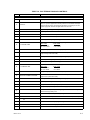
1
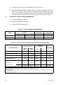
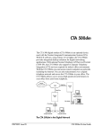
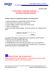
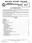
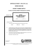
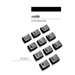
OPERATOR’S MANUAL
HIGH VOLTAGE BIPOLAR
POWER SUPPLY
MODEL
KEPCO INC.
An ISO 9001 Company.
BOP 500M, BOP 500DM
BOP 1000M, BOP 1000DM
POWER SUPPLY
IMPORTANT NOTES:
1)
This manual is valid for the following Model and associated serial numbers:
MODEL
SERIAL NO.
REV. NO.
2)
A Change Page may be included at the end of the manual. All applicable changes and
revision number changes are documented with reference to the equipment serial numbers. Before using this Instruction Manual, check your equipment serial number to identify
your model. If in doubt, contact your nearest Kepco Representative, or the Kepco Documentation Office in New York, (718) 461-7000, requesting the correct revision for your
particular model and serial number.
3)
The contents of this manual are protected by copyright. Reproduction of any part can be
made only with the specific written permission of Kepco, Inc.
Data subject to change without notice.
KEPCO®
©2011, KEPCO, INC
P/N 228-1733-b
THE POWER SUPPLIER™
KEPCO, INC. z 131-38 SANFORD AVENUE z FLUSHING, NY. 11355 U.S.A. z TEL (718) 461-7000 z FAX (718) 767-1102
email: [email protected] z World Wide Web: http://www.kepcopower.com
OPERATOR
SAFETY INSTRUCTIONS
Read these safety instructions, as well as the applicable installation and operating instructions contained in
this manual before using the power supply.
WARNING
Do not touch the output terminals. The high voltage output is dangerous. Electric shock can cause injury or
death.
Do not remove the cover or disassemble the unit. There are no operator serviceable components or
adjustments inside the unit. High voltage components inside the unit can cause serious injury even with
input power disconnected.
Service must be referred to authorized personnel. Using the power supply in a manner not specified by
Kepco. Inc. may impair the protection provided by the power supply. Observe all safety precautions noted
throughout this manual. The following table lists symbols used on the power supply or in this manual where
applicable.
SAFETY SYMBOLS
SYMBOL
Meaning
WARNING: RISK OF ELECTRIC SHOCK.
INDICATES THE POSSIBILITY OF BODILY INJURY OR DEATH.
!
CAUTION: REFER TO REFERENCED PROCEDURE.
INDICATES THE POSSIBILITY OF EQUIPMENT DAMAGE.
CAUTION
If this power supply is used in OEM equipment, the OEM equipment manufacturer is responsible for
attaching appropriate warning labels on the OEM equipment.
Operating the power supply outside the specified limits for input voltage, temperature, or other environmental conditions noted in this manual can damage the power supply and void the warranty.
Safety Messages
The BOP HV protection circuit is designed to protect the load against unregulated high voltages. Upon
sensing a high temperature signal, the protection circuit shuts down the output stage before the overtemperature can destroy the transistors. In addition to that, the protection circuit shuts down the output stage
when there is a lapse of AC input power for more than 8 ms. This feature is provided so as to avoid an
uncontrolled output signal during the shut OFF of the power supply.
BOP-HV/ 112211
Declaration of Conformity
Application of Council directives:
73/23/EEC (LVD)
93/68/EEC (CE mark)
Standard to which Conformity is declared:
EN61010-1:2001
(Safety requirements for electrical equipment for measurement,
control and laboratory use - Part 1)
Manufacturer's Name and Address:
KEPCO INC.
131-38 SANFORD AVENUE
FLUSHING, N.Y. 11355 USA
Importer's Name and Address:
OPY
C
E
V
I
T
A
T
N
REPRESE
Type of Equipment:
Component Power Supply
Model No.:
[PRODUCT MODEL NUMBER]
Year of Manufacture:
I, the undersigned, declare that the product specified above, when used in conjunction with the conditions of conformance set forth in the product instruction manual, complies with the requirements of the
Low Voltage Directive 73/23/EEC, which forms the basis for application of the CE Mark to this product.
Place:
KEPCO Inc.
131-38 Sanford Ave.
Flushing, N.Y.11355 USA
Saul Kupferberg
(Full Name)
Date:
228-1348 DC-COMP/INST 112211
VP OF SALES
(position)
A
Conditions of Conformance
When this product is used in applications governed by the requirements of the EEC, the following restrictions and conditions apply:
1. For European applications, requiring compliance to the Low Voltage Directive, 73/23/EEC, this power
supply is considered a component product, designed for "built in“ applications. Because it is incomplete in construction, the end product enclosure must provide for compliance to any remaining electrical safety requirements and act as a fire enclosure. (EN61010-1 Cl. 6, Cl. 7, Cl.8, Cl. 9 and EN610101 annex F)
2. This power supply is designed for stationary installation, with mains power applied via a detachable
power supply cord or via direct wiring to the source power terminal block.
3. This power supply is considered a Class 1 (earthed) product, and as such depends upon proper connection to protective earth for safety from electric shock. (EN61010-1 Cl. 6.5.4)
4. This power supply is intended for use as part of equipment meant for test, measurement and laboratory use, and is designed to operate from single phase, three wire power systems. This equipment
must be installed within a suitably wired equipment rack, utilizing a three wire (grounded) mains connection. See wiring section of this manual for complete electrical wiring instructions. (EN61010-1 Cl.
6.5.4 and Cl.6.10.1)
5. This power supply has secondary output circuits that are considered hazardous, and which exceed
240 VA at a potential of 2V or more.
6. The output wiring terminals of this power supply have not been evaluated for field wiring and, therefore, must be properly configured by the end product manufacturer prior to use.
7. This power supply employs a supplementary circuit protector in the form of a circuit breaker mounted
on the front panel. This circuit breaker protects the power supply itself from damage in the event of a
fault condition. For complete circuit protection of the end product, as well as the building wiring, it is
required that a primary circuit protection device be fitted to the branch circuit wiring. (EN61010-1 Cl.
9.6.2)
8. Hazardous voltages are present within this power supply during normal operation. All operator adjustments to the product are made via externally accessible switches, controls and signal lines as specified within the product operating instructions. There are no user or operator serviceable parts within
the product enclosure. Refer all servicing to qualified and trained Kepco service technicians.
B
228-1351 COND/CONFORM 112211
SAFETY INSTRUCTIONS
1. Installation, Operation and Service Precautions
This product is designed for use in accordance with EN 61010-1 and UL 3101 for Installation Category 2,
Pollution Degree 2. Hazardous voltages are present within this product during normal operation. The product should never be operated with the cover removed unless equivalent protection of the operator from
accidental contact with hazardous internal voltages is provided:
!
There are no operator serviceable parts or adjustments within the product enclosure.
Refer all servicing to trained service technician.
!
Source power must be removed from the product prior to performing any servicing.
!
This product is factory-wired for the nominal a-c mains voltage indicated on the rating nameplate located adjacent to the source power connection on the product's rear
panel. To reconfigure the product input for other nominal mains voltages as listed
herein, the product must be modified by a trained service technician.
2. Grounding
This product is a Class 1 device which utilizes protective earthing to ensure operator safety.
!
The PROTECTIVE EARTHING CONDUCTOR TERMINAL must be properly connected prior to application of source power to the product (see instructions on installation herein) in order to ensure safety from electric shock.
PROTECTIVE EARTHING CONDUCTOR TERMINAL - This symbol indicates the
point on the product to which the protective earthing conductor must be attached.
EARTH (GROUND) TERMINAL - This symbol is used to indicate a point which is
connected to the PROTECTIVE EARTHING TERMINAL. The component installer/
assembler must ensure that this point is connected to the PROTECTIVE EARTHING TERMINAL.
CHASSIS TERMINAL -This symbol indicates frame (chassis) connection, which is
supplied as a point of convenience for performance purposes (see instructions on
grounding herein). This is not to be confused with the protective earthing point, and
may not be used in place of it.
3. Electric Shock Hazards
This product outputs hazardous voltage and energy levels as a function of normal operation. Operators
must be trained in its use and exercise caution as well as common sense during use to prevent accidental
shock.
This symbol appears adjacent to any external terminals at which hazardous voltage
levels as high as 500V d-c may exist in the course of normal or single fault conditions.
!
This symbol appears adjacent to any external terminals at which hazardous voltage
levels in excess of 500V d-c may exist in the course of normal or single fault conditions.
228-1352 SAFETY - (COVER REMOVAL) 112211
C/(D BLANK)
TABLE OF CONTENTS
SECTION
PAGE
SECTION 1 - INTRODUCTION
1.1
1.2
1.3
1.4
1.5
1.6
1.7
Scope of Manual ..................................................................................................................................... 1-1
General Description................................................................................................................................. 1-1
Electrical Specifications, General............................................................................................................ 1-1
Electrical Specifications, Performance .................................................................................................... 1-2
Miscellaneous Features .......................................................................................................................... 1-4
Mechanical Specifications ....................................................................................................................... 1-6
Accessories ............................................................................................................................................. 1-7
SECTION 2 - INSTALLATION
2.1
2.2
2.3
2.4
2.5
2.6
Unpacking And Inspection....................................................................................................................... 2-1
Terminations............................................................................................................................................ 2-1
A-C Power Input Requirements............................................................................................................... 2-4
Cooling .................................................................................................................................................... 2-4
Preliminary Checkout .............................................................................................................................. 2-4
Installation ............................................................................................................................................... 2-6
SECTION 3 - OPERATION
3.1
3.2
3.2.1
3.2.2
3.3
3.3.1
3.3.2
3.3.3
3.4
3.4.1
3.4.2
3.4.3
Introduction.............................................................................................................................................. 3-1
BOP Operation with Local (Front Panel) Output Control......................................................................... 3-7
Voltage Mode Operation with Current Limiting .................................................................................. 3-7
Current Mode Operation with Voltage Limiting .................................................................................. 3-7
BOP Operation with Remote Control of the Voltage Control Channel .................................................... 3-8
Remote D-C Output Voltage Control By Resistance ......................................................................... 3-8
Remote D-C Voltage Control By Means of D-C Signal Voltage ........................................................ 3-10
The BOP as an Amplifier ................................................................................................................... 3-11
BOP Operation with Remote Control of the Current Control Channel..................................................... 3-14
Remote Control of the Bop Current Channel..................................................................................... 3-15
Remote Control of the Bop Current Limit........................................................................................... 3-19
Remote Control of the BOP Voltage Limit ......................................................................................... 3-21
BOPHVSVC112211
i
LIST OF FIGURES
FIGURE
1-1
1-2
1-3
1-4
2-1
2-2
2-3
2-4
2-5
3-1
3-2
3-3
3-4
3-5
3-6
3-7
3-8
3-9
3-10
3-11
3-12
3-13
3-14
3-15
3-16
3-17
3-18
3-19
3-20
3-21
3-22
3-23
3-24
3-25
3-26
3-27
3-28
ii
TITLE
PAGE
BOP (High Voltage) Operational Power Supply ............................................................................................ iv
BOP Output Characteristic ......................................................................................................................... 1-4
BOP Output Waveform with Phase Shift.................................................................................................... 1-5
Mechanical Outline Drawing, BOP – HV .................................................................................................... 1-8
Location of Internal Calibration Controls .................................................................................................... 2-1
BOP Terminations and Controls................................................................................................................. 2-2
A-C Source Voltage Selector, Location...................................................................................................... 2-4
Rear Programming Connector Wired For Front Panel Operation .............................................................. 2-5
Rack Installation of the BOP ...................................................................................................................... 2-6
BOP Voltage Control Channel.................................................................................................................... 3-2
BOP Current Control Channel.................................................................................................................... 3-3
BOP (±) Voltage Limiting Circuit................................................................................................................. 3-3
BOP (±) Current Limiting Circuit................................................................................................................. 3-4
Basic 2-Wire Load Connection and Grounding Connections
Between the BOP and the Load .............................................................................................................. 3-4
Load Connection with Error Sensing and Grounding Connections
Between the BOP and the Load .............................................................................................................. 3-5
Remote Potentiometer Control of the BOP D-C Output Voltage................................................................ 3-9
Remote D-C Output Voltage Control By Means of a Two
Terminal Resistance (Decade) ................................................................................................................ 3-9
Digital Control of the BOP D-C Output Voltage.......................................................................................... 3-10
BOP D-C Output Voltage Control with a High Impedance, (±) 1V Signal Source ...................................... 3-11
Graphs of Possible BOP Input/Output Waveshapes.................................................................................. 3-12
Basic Programming Circuit for Use of the BOP as a
Bipolar Amplifier (Voltage Mode)............................................................................................................. 3-13
Programming Circuit for Driving the BOP Output
Voltage with a Bipolar (±1V) Signal ........................................................................................................ 3-14
Programming Circuit for Driving the BOP Output Voltage with a High
Impedance Source, Using the Non-inverting Input of the Pre-amplifier .................................................. 3-15
Local (Front Panel) Control of the BOP Output Current
with the Bipolar Current Control .............................................................................................................. 3-15
Remote Potentiometer Control of the BOP Output Current ....................................................................... 3-16
Remote Output Current Control By Means of a Two Terminal Resistance................................................ 3-16
Digital Control of the BOP Output Current ................................................................................................. 3-17
BOP Output Current Control with a High Impedance (±) 1 Volt Signal Source.......................................... 3-17
Basic Programming Circuit for Use of the BOP as a Bipolar
Current Stabilized Amplifier ..................................................................................................................... 3-18
Programming Circuit for Driving the BOP Output Current with a Bipolar
Signal Less Than ±10V (Example Shown: ±1V Source) ......................................................................... 3-18
Programming Circuit for Driving the BOP Output Current with a
High Impedance Source .......................................................................................................................... 3-19
Local (Front Panel) Control of the BOP Current Limit Circuits ................................................................... 3-20
Symmetrical Remote Control of the BOP Current Limits ........................................................................... 3-20
Independent Remote Control of the BOP (+) IO and (–) IO Limits ............................................................. 3-21
Local (Front Panel) Control of the BOP Voltage Limit Circuits................................................................... 3-21
Symmetrical Remote Control of the BOP Voltage Limit Circuit.................................................................. 3-22
Independent Remote Control of the BOP Voltage Limit Circuits................................................................ 3-22
BOP1000SVC 112211
LIST OF TABLES
TABLE
1-1
1-2
1-3
2-1
2-2
TITLE
PAGE
Output Ranges and Impedance ..................................................................................................................1-2
Output Effects, Offsets and Reference Specifications ................................................................................1-2
Dynamic Specifications ...............................................................................................................................1-4
Internal Calibration Controls .......................................................................................................................2-1
BOP Terminations and Controls .................................................................................................................2-3
BOP1000SVC112211
iii
FIGURE 1-1.
iv
BOP (HIGH VOLTAGE) OPERATIONAL POWER SUPPLY
BOPSVC112211 /1107/1108
SECTION 1 - INTRODUCTION
1.1
SCOPE OF MANUAL
This manual contains instructions for the installation and operation of the Models BOP 500M,
BOP 500DM, BOP 1000M and BOP 1000DM Bipolar Operation Power Supplies, manufactured
by Kepco, Inc., Flushing, New York, U.S.A.
1.2
GENERAL DESCRIPTION
The Kepco Model BOP 500M and BOP 1000M are high voltage power sources, which combine
the capabilities of fast programmable power supplies with a Class A output stage, which can
respond bidirectionally from zero. Models with the DM suffix are similar to M suffix models,
except that the analog front panel meters are replaced by digital meters. The “BOP” can be
operated in a “Voltage Stabilizing” or “Current Stabilizing” operating mode (selectable by a front
panel switch). The BOP incorporates two separate control channels, for local (front panel) or
remote control of the output current and the output voltage. In addition, bounding currents for
bipolar voltage and current limiting are provided which may be adjusted manually (by front panel
controls) or can be remotely programmed. All control and bounding channels are connected to
the bipolar (Class A) output stage via an “EXCLUSIVE-OR” gate, so that only one circuit is in
control of the BOP output at any one time. Some applications are listed below:
A)
VOLTAGE MODE OPERATION. (Current limiting either front panel adjusted or remotely
programmed using the current limiting channel).
1) High speed, bipolar d-c voltage source (remote or locally controlled output).
2) Scaling or summing amplifier with or without d-c bias.
B)
CURRENT MODE OPERATION. (Voltage limiting either front panel adjusted or remotely
programmed using the voltage limiting channel).
1) High speed, bipolar d-c current source (remote or locally controlled output).
2) Amplification of a-c currents with or without d-c bias.
The main chassis of the Model BOP Operational Power Supply/Amplifier is constructed of
plated steel. The wrap-around cover is perforated steel, plated and painted in a dark gray texture. The front panel material is aluminum, treated and painted light gray (Color 26440 per Fed.
Std. 595). The major part of the circuitry is located on plug-in type circuit boards for convenient
access.
1.3
BOPHV112211
ELECTRICAL SPECIFICATIONS, GENERAL
A)
INPUT SOURCE REQUIREMENTS: 105 to 125Vac or 210 to 250Vac, 50 to 65 Hz, selectable by the SOURCE VOLTAGE SELECTOR SWITCH (refer to Section 2, Fig. 2-3). Power
consumption approximately 250 Watts. Power factor: 0.8. The primary circuit is protected
by a fuse.
B)
OPERATING TEMPERATURE RANGE: -20°C TO +65°C.
C)
STORAGE TEMPERATURE RANGE: -40°C to +85°C.
1-1
1.4
D)
COOLING: Forced air using a d-c fan blowing to the rear of the unit.
E)
ISOLATION FROM GROUND: The BOP circuitry, its output and programming terminals
have no d-c connection to the chassis. The COMMON terminal of the BOP can be operated up to 500 volts (d-c or peak a-c) off ground. The common mode current (leakage from
output to ground) is less than 50µA (rms) or 200µA (p-p) at 115Vac power input, 60 Hz.
ELECTRICAL SPECIFICATIONS, PERFORMANCE
A)
OUTPUT RANGES: See Table 1-1.
B)
OUTPUT IMPEDANCE: See Table 1-1.
C)
OUTPUT EFFECTS: See Table 1-2.
TABLE 1-1. OUTPUT RANGES AND IMPEDANCE
OUTPUT IMPEDANCE
d-c OUTPUT
RANGE
MODEL
VOLTAGE MODE
CURRENT MODE
VOLTS
mA
d-c OHMS + SERIES L
d-c OHMS + SHUNT C
BOP 500M
-500 TO +500
-80 TO +80
0.05Ω +5mH
100MΩ +0.3µF
BOP 1000M
-1000 TO +1000
-40 TO +40
0.2Ω +50mH
400 MΩ + 0.4µF
TABLE 1-2. OUTPUT EFFECTS, OFFSETS AND REFERENCE SPECIFICATIONS
OUTPUT EFFECTS
(1)
PRE-AMPLIFIER
OFFSETS
REFERENCES
INFLUENCE QUANTITY
VOLTAGE
MODE
CURRENT
MODE
∆ EIO
∆ IIO
SOURCE: 105-125/210-250Va-c
<0.0005%
<0.0005%(5)
<5µV(4)
<1nA
<0.0005%
LOAD: No Load - full load
<0.0005%
<0.005%
_
_
<0.0005%
TIME: 8-hour (drift)
<0.01%
<0.01%
<20µV
(4)
<1nA
<0.005%
TEMPERATURE: Per °C
<0.01%
<0.01%
<20µV
(4)
<1nA
<0.005%
<10 mV
<25µA(4)
_
_
<10µV
<500µA(4)
_
_
<100µV
UNPROGRAMMED OUTPUT
DEVIATION:
(2)
(Ripple and Noise)
rms
p-p
<200 mV
(3)
(1) Specifications are expressed as a percentage of the nominal power supply output (either voltage or current for either BOP 500M or BOP 1000M).
(2) Common terminal grounded so that the common-mode current does not flow through the load.
(3) 20 Hz to 10 MHz.
(4) For frequency components in the bandwidth of the current stabilizer. Beyond cutoff, noise will appear as a voltage component equal to the rated
voltage mode noise.
(5) Or 0.2 mA, whichever is greater.
1-2
BOPHV112211
NOTE: In this instruction manual, Kepco will follow the NEMA standards for d-c Power Supplies
and speak of the “Output Effects,” caused by changes in the “Influence Quantities.” The
“Output Effects” are specified either as a percentage change, referred to the maximum
specified output voltage (EO) or current (IO), or as an absolute change (∆EO, ∆IO), directly in
millivolts or milliamperes or both. The illustration below will clarify the NEMA terms.
INFLUENCE QUANTITIES
1) SOURCE
2) LOAD
3) TEMPERATURE
4) TIME
1) DUE TO SOURCE
2) DUE TO LOAD
3) DUE TO TEMPERATURE
4) DUE TO TIME
D)
= SOURCE EFFECT....................................................................(FORMERLY LINE REGULATION)
= LOAD EFFECT .........................................................................(FORMERLY LOAD REGULATION)
= TEMPERATURE EFFECT COEFFICIENT ...............................(FORMERLY TEMPERATURE COEFFICIENT)
= DRIFT........................................................................................(FORMERLY STABILITY)
The BOP output effects, in response to the tabulated variation in the INFLUENCE QUANTITIES, are given in Table 1-2 for the built-in input and feedback resistor values of the voltage and current channel preamplifiers.The tabulated OFFSET values (see Table 1-2) may
be used to calculate the BOP output effects if the BOP voltage or current channel is
remotely programmed and different values for the feedback resistors (Rf) and the input
resistors (Ri) are used. In this case, the tabulated preamplifier offsets and the values of the
feedback and input resistors are combined in an “Error Equation”, which represents the
“Worst Case” output effect for the application at hand:
VOLTAGE MODE: ∆ EO = G [±∆Eio (1 + Rf /Ri) ± ∆ Iio Rf ± ∆ Eref]
1
CURRENT MODE: ∆ IO = ----------------- [±∆Eio (1 + Rf /Ri) ± ∆ Iio Rf ± ∆ Eref]
10xR s
RS = CURRENT SENSING RESISTOR (BOP 500M = 12.5Ω, BOP 1000M = 25Ω)
∆IO =TOTAL OUTPUT CURRENT CHANGE
G = CLOSED LOOP GAIN (BOP 500M = 50, BOP 1000M = 100)
WHERE:
∆EO
∆Eref
∆Eio
∆Iio
Rf
Ri
= TOTAL OUTPUT VOLTAGE CHANGE
= CHANGE IN THE VOLTAGE REFERENCE
= CHANGE IN OFFSET VOLTAGE
= CHANGE IN OFFSET CURRENT
= EXTERNAL FEEDBACK RESISTOR
= EXTERNAL INPUT RESISTOR
NOTE: Variations in the value of the feedback and input resistors are considered secondary effects in the
Error Equation.
BOPHV112211
1-3
E)
DYNAMICS: The dynamic response of the BOP output are tabulated in Table 1-3 in both
the time domain (Output response to a step program) and in the frequency domain (bandwidth) for large and small signals.
TABLE 1-3. DYNAMIC SPECIFICATIONS
VOLTAGE CHANNEL
CURRENT CHANNEL
DYNAMIC SPECIFICATIONS
BOP 500M
BOP 1000M
BOP 500M
BOP 1000M
Closed Loop Gain
50 V/V
100 V/V
8 mA/V
4 mA/V
Bandwidth [d-c to f-3 dB]
5.3 KHz
1.8 KHz
2.0 KHz
1.5 KHz
Programming Time Constant
30 µsec.
88 µsec.
80 µsec
106 µsec.
6 KHz
1.9 KHz
2.5 KHz
1.6 KHz
18V/µsec.
12V/µsec.
1.25 mA/µsec
0.4 mA/µsec.
25 µsec.
75 µsec.
25 µsec.
50 µsec.
Large Signal Frequency Response
Slewing Rate
Load Recovery Time Constant
1.5
MISCELLANEOUS FEATURES
A)
OUTPUT RANGE: The BOP can be locally (front panel) adjusted, or remotely programmed,
from (-) 100% to (+)100% of its specified d-c voltage and current range. The Class A bipolar
output stage permits operation as either a SOURCE OR A SINK. (See FIG. 1-2.)
NOTE: Operation in the second and fourth quadrants of the graph shown in FIG 1-2 must be
derated as indicated.
FIGURE 1-2.
1-4
BOP OUTPUT CHARACTERISTIC
BOPHV112211
NOTE: The BOP is operating as a SOURCE if the direction of its output voltage is the same as the
direction of its output current. The BOP is operating as a SINK if the direction of its output
voltage is opposite that of its output current. An illustrative case is shown in FIG. 1-3,
where the BOP is programmed to deliver a sine wave output and where the load produces a
phase shift between the output voltage and current.
FIGURE 1-3.
BOP OUTPUT WAVEFORM WITH PHASE SHIFT
B)
REFERENCES: Two reference/bias sources (± 10V - 1 mA MAX.) are provided for control
and biasing purposes. These reference sources are available at the rear programming connector (with reference to the “COMMON” terminal). Their specifications are tabulated in
Table 1-2.
C)
OFFSET NULLING: Controls are provided to zero the initial offsets (Eio, Iio) of both the voltage and current control preamplifiers.
D)
LOAD REACTANCE: To realize the full high speed potential of the BOP, the load characteristics should be mainly resistive. Load capacitance and inductance up to 0.01µF and 0.5
mHy respectively can be tolerated without performance deterioration.
CAUTION: Stable operation into a purely inductive load in the Current Mode of operation requires a minimum series resistance of 25 ohms.
E)
BOPHV112211
SERIES OR PARALLEL OPERATION: Not recommended.
1-5
F)
VOLTAGE CONTROL CHANNEL (refer to Section 3 - FIG. 3-1). The BIPOLAR VOLTAGE
AMPLIFIER, with a fixed gain of 50 (BOP 500M) or 100 (BOP 1000M) is connected, via the
MODE switch, to the (unity gain) VOLTAGE PREAMPLIFIER. If the BIPOLAR VOLTAGE
SWITCH is “on”, the BOP output voltage can be locally controlled by means of the (front
panel) (±) 10 volt bias source from (-) 100% (through zero) to (+) 100% of the rated value.
The VOLTAGE PREAMPLIFIER is provided with a ZERO control and all its terminals are
available at the rear programming connector for remote control of the output voltage. Control methods are described in Section 3 of this manual.
G)
MODE SWITCH: The BOP is equipped with a front panel mounted MODE SWITCH, which
selects bipolar voltage or bipolar current control.
H)
CURRENT CONTROL CHANNEL (refer to Section 3 - FIG. 3-2) The BIPOLAR CURRENT
AMPLIFIER, with fixed gain of 8 mA/V (BOP 500M) or 4 mA/V (BOP 1000M), is connected
via the MODE switch to the (unity gain) CURRENT PREAMPLIFIER. If the BIPOLAR CURRENT SWITCH is “on”, the BOP output current can be locally (front panel) controlled (by
means of the ±10 volt bias source) from (-) 100% (through zero) to (+) 100% of the rated
value. The CURRENT PREAMPLIFIER is provided with a ZERO control and all its terminals are available at the rear programming connector for remote control of the output current. Control methods are described in Section 3 of this manual. I)
J)
BOUNDING: (refer to Section 3 - FIG. 3-3 and 3-4). The BOP has four adjustable output
voltage/current limiting circuits: (-) EO LIMIT, (+) EO LIMIT, (-) IO LIMIT, (+) IO LIMIT for
overvoltage/overcurrent protection in either operating mode. All limiting circuits can be
screwdriver adjusted by means of four front panel controls. In addition, all four limits can be
remotely controlled by means of 0 to 10 volts d-c control voltages. The four limits may be
programmed independently or the (±) voltage and (±) current limits can be controlled in
pairs. The adjustable/programmable limit controls are backed-up by non-adjustable limit
circuits which define the four boundaries [(±) EO MAX. and (±) IO MAX.] of the BOP, and
provide protection against accidental overprogramming of the adjustable limits.
K)
MODE LIGHTS AND FLAG SIGNAL OUTPUT: Four (4) front panel (LED type) indicator
lamps monitor the prevailing operating mode of the BOP. In addition, four (4) corresponding
flag signal outputs are provided at the rear programming connector. For each operating
condition (VOLTAGE MODE, CURRENT MODE, ±EO LIMIT, ±IO LIMIT) the corresponding
indicator lamp lights up and the associated flag signal changes its state from (TTL) logic “1”
to “0”.
NOTE: If operating against back-up current limit (PAR. J) all 4 lights go out. The four lights also
go out after the protection circuit has been energized.
L)
1.6
1-6
STANDARDS: BOP models are designed and tested in accordance with NEMA Standard
for Stabilized Power Supplies, d-c output, Publication No. PY-1-1972.
MECHANICAL SPECIFICATIONS
A)
DIMENSIONS: See “Mechanical Outline Drawing,” FIG. 1-4.
B)
FINISH: See “Mechanical Outline Drawing,” FIG 1-4.
C)
FRONT PANEL METERS: M Suffix: 2-1/2 inches wide, recessed. Accuracy ±2% full scale.
Two (2) “zero center” analog meters monitoring the ±d-c voltage and the ±d-c current are
provided. DM suffix: Analog meters are replaced by digital panel meters, 3-1/2 digits.
±200mV full scale, power requirements: ±5V, ±5%.
BOPHV112211
1.7
BOPHV112211
ACCESSORIES
A)
MOUNTING FLANGES, for installation of the BOP into a standard (19-inch) equipment
rack (refer to Section 2, FIG. 2-5). (A pair included with each BOP). Kepco Part No. 1281282 (right), 128-1281 (left).
B)
REAR PROGRAMMING CONNECTOR, Kepco Model PC-9, 30-terminal printed circuit
connector for all rear programming connections and flag signal outputs (One included with
each BOP).
1-7
FIGURE 1-4.
1-8
MECHANICAL OUTLINE DRAWING, BOP – HV
BOPHV112211
SECTION 2 - INSTALLATION
2.1
UNPACKING AND INSPECTION
This instrument has been thoroughly inspected and tested prior to packing and is ready for
operation. After carefully unpacking, inspect for shipping damage before attempting to operate.
Perform the preliminary operation check as outlined in PAR. 2.5. If any indication of damage is
found, file an immediate claim with the responsible transport service.
2.2
TERMINATIONS
A)
FRONT PANEL: Refer to FIG. 2-2A and Table 2-2.
B)
REAR: Refer to FIG. 2-2B and Table 2-2.
C)
INTERNAL CALIBRATION CONTROLS: Refer to FIG. 2-1 and Table 2-1.
TABLE 2-1. INTERNAL CALIBRATION CONTROLS
REFERENCE DESIGNATION
CONTROL
PURPOSE
ADJUSTMENT PROCEDURE
R18
(±) 10V CAL.
Reference Voltage Calibration
No Operator adjustment allowed.
Refer to Service personnel.
R31
EO ZERO
EO Pre-amp Zero Adjustment
Section 3, Par. 3.3.1C
R36
IO ZERO
IO Pre-amp Zero Adjustment
Section 3, Par. 3.4.1
R303
IOX
IO Stabilization Compensation
No Operator adjustment allowed.
Refer to Service personnel.
FIGURE 2-1.
BOPHV 112211
LOCATION OF INTERNAL CALIBRATION CONTROLS
2-1
FIGURE 2-2.
2-2
BOP TERMINATIONS AND CONTROLS
BOPHV 112211
TABLE 2-2. BOP TERMINATIONS AND CONTROLS
NO.
NAME OF FUNCTION
FUNCTION
NOTE: NUMBERS CORRESPOND TO THOSE SHOWN IN FIGURE 2-2
1
A-C POWER
A-C input Power Switch and Indicator Lamp
2
OUTPUT
Output “READY” lamp energized when a-c power is turned on. If lamp goes off
when a-c power is applied, the internal protection circuit disables the output
and front panel controls. To restore full operation it is necessary to turn the
power supply OFF and then ON again after a few seconds.
3
± OUTPUT, COMMON, GROUND
Output and grounding terminals (parallel with rear barrier strip terminals)
4
MODE
Operating mode selector switch for “VOLTAGE” OR “CURRENT” mode
5
Mechanical voltmeter zero adjustment
6
Mechanical ammeter zero adjustment
7
VOLTAGE LIMIT
LED lamp, indicating voltage limiting operation
8
± VOLTAGE LIMIT
Controls for manual adjustment of the (±) voltage limits
BOP 1000M
BOP 500M
A = 500V TO 0
-1000V TO 0
B = 0 TO +500V
0 TO +1000V
9
EO INPUT
Programming input terminals for voltage pre-amp
10
BIPOLAR VOLTAGE CONTROL
“ON-OFF” switch and voltage control for manual adjustment of the BOP d-c
output voltage (with switch “ON”)
11
EO METER
d-c output voltmeter (reads also average a-c signals)
12
EO MODE
LED lamp, indicating voltage mode operation
13
CURRENT LIMIT
LED lamp, indicating current limiting operation
14
± CURRENT LIMIT
Controls for manual adjustment of the (±) current limits
BOP 500M
BOP 1000M
A = -80mA to 0
-40mA to 0
B = 0 to +80mA
0 to +40mA
15
IO INPUT
Programming input terminals for current pre-amp
16
BIPOLAR CURRENT CONTROL
“ON-OFF” switch and current control for manual adjustment of the BOP d-c
output current (with switch “ON”)
17
IO METER
d-c output ammeter (reads also average a-c signals)
18
IO MODE
LED lamp, indicating current mode operation
19
FUSE
a-c power fuse. Protects primary a-c input circuit
20
a-c power input jack. Accepts 3-wire line cord (supplied)
21
Cable holder, accepts output, sensing and ground wires for feed-through from
terminals through safety cover
22
REAR TERMINALS
Rear barrier strip with output, sensing and ground terminals
23
INTERLOCK
Shuts off BOP if safety cover is removed. Can be defeated by a forward pull
24
INT. IOX CONTROL
R303, compensation adjustment. See Section 5.
25
REAR CONNECTOR
Access to internal circuitry for programming connections
26
INT. CONTROLS
R31, R36, Current and voltage pre-amp zero controls
27
INSULATED TOOL
Use this tool for all internal adjustments
BOPHV 112211
2-3
2.3
A-C POWER INPUT REQUIREMENTS
The BOP is equipped with a SOURCE VOLTAGE SELECTOR permitting the user to choose
between 115 and 230V a-c operation by means of a screwdriver actuated switch; the switch is
accessed by removing the cover.
Remove the wrap-around cover by unscrewing the 18 black oxide screws: two screws on the
top, six screws (2) attaching the mounting flanges, eight screws (3) from the side, and two
screws from the chassis slide support brackets. Do not remove the nickel screws in the chassis
slide support brackets, only remove black oxide screw (4) from each chassis slide support
bracket.
The switch location is illustrated in FIG. 2-3. When changing the a-c input voltage, the A-C
POWER FUSE must be altered as well, according to the information given in FIG.2-3.
FIGURE 2-3.
2.4
A-C SOURCE VOLTAGE SELECTOR, LOCATION
COOLING
The components in the BOP power supply rely on forced air (towards rear panel) cooling for
maintaining their operating temperature. ALL OPENINGS MUST BE KEPT CLEAR FROM ALL
OBSTRUCTIONS TO ENSURE PROPER AIR CIRCULATION. Periodic cleansing of the interior of the power supply is recommended. If the BOP is rack-mounted or installed in confined
spaces, care must be taken that the ambient temperature (the temperature immediately surrounding the power supply) does not rise above 65°C (149°F).
2.5
PRELIMINARY CHECKOUT
A simple operating check after unpacking and before permanent installation, is advisable to
ascertain whether the BOP has suffered damage in shipment. Refer to FIG. 2-2 and Table 2-2.
FOR THE LOCATION AND DESIGNATION OF THE OPERATION CONTROLS AND TERMINALS. Proceed as follows:
A)
Connect the BOP to a 115V a-c source, or refer to PAR. 2.3 for conversion to 230V a-c
operation if required.
NOTE: THE REAR PROGRAMMING CONNECTOR MUST BE ATTACHED TO THE BOP
AND MUST BE WIRED AS SHOWN ON FIG 2-4.
2-4
BOPHV 112211
FIGURE 2-4.
REAR PROGRAMMING CONNECTOR WIRED FOR FRONT PANEL OPERATION
B)
Note: The rear sensing links must be attached to the rear terminals of the BOP as shown in
FIG. 2-2 and the rear connector must be attached and secured.
C)
Set the BOP front panel controls as follows (refer to FIG. 2-2). The controls will be identified here and in the following manual text with the nomenclature used in Table 2-2 and
identifying numbers used in FIG. 2-2):
1)
MODE switch (4), set to “VOLTAGE”.
2)
BIPOLAR VOLTAGE CONTROL (10), set switch to "ON", control to its extreme counterclockwise position.
3)
A-C POWER switch to "ON".
D)
The indicator lamp, part of the A-C POWER switch (1) will be "ON". The "OUTPUT
READY" lamp (2) AND "EO MODE" lamp (12) will also be "ON".
E)
Turn the BIPOLAR VOLTAGE CONTROL (10) clockwise through its range, while observing
the front panel "EO METER" (11). The BOP output voltage should smoothly follow from the
maximum negative output voltage, over zero, to the maximum positive output voltage of
the BOP. Turn A-C POWER SWITCH (1) “OFF”.
F)
Connect a short-circuit between the (±) OUTPUT and the COMMON front panel output terminals (3). Set the BOP front panel controls as follows:
G)
BOPHV 112211
1)
MODE SWITCH (4), set to "CURRENT".
2)
BIPOLAR CURRENT CONTROL (16), set switch to “ON”, control to its maximum
counterclockwise position.
3)
A-C POWER switch "ON".
The indicator lamp, part of the A-C POWER switch (1) will be "ON", the "OUTPUT READY"
LAMP (2) and the "IO MODE" lamp (18) will be "ON".
2-5
H)
2.6
Turn on BIPOLAR CURRENT CONTROL (16) clockwise through its range, while observing
the front panel “IO METER” (17). The BOP output current should smoothly follow from the
maximum negative output current, over zero, to the maximum positive output current of the
BOP. Turn A-C POWER switch (1) “OFF”. Remove the short circuit from the output terminals. THIS CONCLUDES THE PRELIMINARY CHECK-OUT OF THE BOP.
INSTALLATION (Refer to FIG. 2-5)
The BOP is delivered with mounted SLIDE SUPPORT BRACKETS and MOUNTING FLANGES
and ready for installation into any standard (19-inch) instrument rack. Please refer to PAR 2.4
(COOLING) if the BOP is to be mounted into a multiple rack installation.
FIGURE 2-5.
2-6
RACK INSTALLATION OF THE BOP
BOPHV 112211
SECTION 3 - OPERATION
3.1
INTRODUCTION
BOP BIPOLAR OPERATIONAL POWER SUPPLIES can be used in a great variety of applications. As a PRECISION VOLTAGE or CURRENT SOURCE, the BOP output can be controlled
locally (by means of the front panel BIPOLAR voltage and current controls) or remotely (by
means of resistances or by voltage signals). Independently adjustable (or remotely programmable) limit circuits for both output voltage and output current protect a sensitive load from any
overvoltage or overcurrent. As a BIPOLAR AMPLIFIER, the BOP output responds to such input
signals as sine, square or triangular waves. A (±) 10 volt input signal will program the BOP output (voltage or current) through its rated output ranges. Built-in preamplifiers, for the voltage, as
well as the current channel of the BOP, permit amplification of the control signals to the required
amplitude and the interface with high as well as low impedance signal sources.
Detailed examples of the more popular applications are described in the following paragraphs.
Before actual operation, however, the following general comments on the operation of the BOP
should be carefully considered:
WARNING
BOPHV112211
1)
THIS EQUIPMENT IS CAPABLE OF PRODUCING LETHAL VOLTAGES. Exercise
extreme care in making all connections to and from the BOP terminals. REMOVE A-C
POWER FROM THE BOP BEFORE MAKING ANY CONNECTIONS!
2)
An interlock device removes the A-C source power from the BOP if the rear terminal
cover plate if lifted. DO NOT BYPASS THE INTERLOCK.
3)
Wires and/or cables, connected from the BOP terminals to external components or
programming devices must be properly insulated and securely terminated on both
sides to avoid accidental contact. A feed-through hole is provided on the BOP rear terminal cover, to bring the wires from the BOP rear terminals to the outside. DO NOT
USE BANANA PLUGS WITH EXPOSED SCREWS OR OTHER EXPOSED METAL
PARTS AT THE FRONT PANEL OUTPUT TERMINALS!
4)
The BOP chassis and cover must be safety-grounded to a reliable a-c source ground.
A safety ground may be established by using a grounded a-c power outlet or, if the latter is not available, by means of a separate wire, from a provided “ground” terminal to a
reliable a-c source ground point.
5)
THE COMMON OUTPUT TERMINAL OF THE BOP SHOULD BE SIGNAL
GROUNDED. If for any reason, grounding of the output is not possible, additional precautions must be taken to make any access to the isolated output impossible.
6)
FOR ALL CONTROL ADJUSTMENTS ON THE BOP, USE ONLY THE INSULATED
TOOL WHICH IS ATTACHED AT THE REAR. (See Section 2, FIG. 2-2).
3-1
A)
DIAGRAMS. Application and test set-up diagrams on the following pages show the symbolic and simplified representation of the BOP circuitry in four (4) separate diagrams, as
indicated on FIGS. 3-1 through 3-4. The diagrams represent the four programmable circuits of the BOP.
1) Voltage Control Channel (FIG 3-1)
2) Current Control Channel (FIG 3-2)
3) (±) EO Limit Circuits (FIG 3-3)
4) (±) IO Limit Circuits (FIG 3-4)
The complete simplified diagram is represented at the beginning of Section 4 (see FIG.
4-1). THE FOUR CIRCUITS CAN BE PROGRAMMED SEPARATELY AS DESCRIBED
IN THE EXAMPLES IN THIS SECTION, OR THEY CAN BE USED SIMULTANEOUSLY
AS AN APPLICATION REQUIRES, WITH THE EXCEPTION OF THE TWO (2) MAIN
BIPOLAR VOLTAGE AND CURRENT CHANNELS WHICH ARE SELECTED BY THE
FRONT PANEL MODE SWITCH AND CANNOT BE OPERATED SIMULTANEOUSLY.
The numbered terminals in the diagrams correspond to the connector terminals on the
REAR PROGRAMMING CONNECTOR.
NOTE: BOP’s have front and rear output terminals. Only the front terminals are shown
on all subsequent simplified diagrams.
FIGURE 3-1.
3-2
BOP VOLTAGE CONTROL CHANNEL
BOPHV112211
BOPHV112211
FIGURE 3-2.
BOP CURRENT CONTROL CHANNEL
FIGURE 3-3.
BOP (±) VOLTAGE LIMITING CIRCUIT
3-3
FIGURE 3-4.
B)
LOAD CONNECTION (I): The basic interconnection between the BOP and the load are
shown in FIG. 3-5. The load wire size for the 2-wire connection shown should be as large
as practicable to keep the series resistance and inductance low. In addition, the load wire
pair should be tightly twisted, to reduce possible “pick-up” from stray magnetic fields. The
basic 2-wire connection is useful where the voltage drop in the load wires is of minor consequence, as for example, operation into a constant load or in a constant current operating
mode.
FIGURE 3-5.
3-4
BOP (±) CURRENT LIMITING CIRCUIT
BASIC 2-WIRE LOAD CONNECTION AND GROUNDING CONNECTIONS
BETWEEN THE BOP AND THE LOAD
BOPHV112211
C)
LOAD CONNECTION (II). The recommended load connection for all applications requiring
minimum load effect across a remote load is shown in FIG. 3-6. A twisted, shielded pair of
wires (AWG No. 20 minimum) is connected from the BOP sensing terminals to the load.
This “remote error sensing” technique will compensate for load wire voltage drops up to 0.5
volts per wire.
NOTE: OBSERVE POLARITIES:THE COMMON SENSING WIRES MUST GO TO THE
COMMON LOAD WIRE. THE (±) OUTPUT SENSING WIRE MUST GO TO THE (±)
OUTPUT LOAD WIRE.
FIGURE 3-6.
LOAD CONNECTION WITH ERROR SENSING AND GROUNDING CONNECTIONS
BETWEEN THE BOP AND THE LOAD
WARNING
BOPHV112211
D)
A-C SAFETY GROUND. (Refer to FIG's 3-5, 3-6). The dangerous voltages present in this
equipment make it imperative that the case be kept at ground potential at all times. It is sufficient to use a 3-wire line cord with 3-prong safety plug (supplied with this equipment) in
combination with a properly grounded outlet. If an adapter for a non-grounded outlet is
used, however, the case must be grounded separately. A separate “GROUND terminal is
provided for this purpose on the rear of the BOP. (See Section 2, FIG. 2-2).
E)
DC (SIGNAL) GROUND. (Refer to FIG.'s 3-5, 3-6). Specified ripple and noise figures for
operational power supplies are valid only with the common side of the output/load circuit
returned to a common ground point (refer to Section 1, Table 1-2). The common side of the
BOP output is shown grounded in FIG's 3-5 and 3-6, since it is “common” to both internal
reference source and any external signal source. If the application requires, the “common”
side of the BOP may be floated up to 500V d-c off ground. In this case, however, the common mode current (specified in Section 1, PAR. 1.3E), will flow through the impedance of
whatever circuit is placed between common and ground and will give rise to a common
mode voltage. The signal ground point in the BOP/load circuit must consist of a single point
3-5
only, to which all input source grounds, shields and load grounds are connected. Multiple
signal grounds in the BOP output/load circuit may cause “ground loop” problems, since
noise signals develop across the impedance between the multiple ground points. The
exact physical location of the “best” single ground must be carefully selected for minimum
ripple/noise output.
F)
EXTERNAL PROGRAMMING RESISTORS. External programming resistors should be
components with low-temperature coefficients. Resistors should be selected carefully,
since in most applications, the limitations for stability and drift are due, not to the BOP, but
to the programming resistors. Selection criteria for resistors are:
1) TEMPERATURE COEFFICIENT
2) LEAKAGE (IN VALUES ABOVE 100k OHM)
3) HUMIDITY EFFECTS
4) DRIFT WITH TIME
5) SELF-HEATING (POWER DISSIPATION)
6) TOLERANCE
G)
For variable resistors (potentiometers or rheostats) similar selection criteria apply. In addition such specifications as listed below should be carefully considered if the application
requires:
1) END RESISTANCE
2) LINEARITY
3) CAPACITIVE AND INDUCTIVE EFFECTS
H)
ACTIVE PROGRAMMING SOURCES. External programming sources (Signal Generators,
etc.) or reference sources should have temperature coefficients and drift specifications
comparable to (or better than) the BOP Power Supply. I)
CAUTION: A-C source operated programming sources must have their output isolated
from the case.
3-6
J)
EXTERNAL LEADS. Shielded (preferably twisted) lead pairs are recommended for all input
connections to the BOP control channels. The shield should be connected (single-ended)
to the chosen signal ground point. Shielded leads should be held as short as practicable.
Output leads must be “high-voltage” wire, rated at least for the maximum BOP output voltage and current.
K)
BEFORE USING THE BOP IN ANY APPLICATION....PLEASE REFER TO SECTION 2 TO
GET ACQUAINTED WITH THE OPERATING CONTROLS AND THE A-C POWER
REQUIREMENTS. REFER TO THIS SECTION (SECTION 3) FOR INFORMATION ON
LOAD CONNECTIONS AND GROUNDING. READ THE “WARNING” NOTES PRIOR TO
PAR. 3.1A.
BOPHV112211
3.2
BOP OPERATION WITH LOCAL (FRONT PANEL) OUTPUT CONTROL
3.2.1
VOLTAGE MODE OPERATION WITH CURRENT LIMITING
The BOP may be used as a stabilized (d-c) source of positive or negative voltage with output
current limiting for either polarity pre-selected for the application at hand.
1)
Determine the output current and voltage requirement of your load. Set the BOP MODE
SWITCH to the VOLTAGE position and the BIPOLAR VOLTAGE CONTROL switch to ON.
2)
With the BOP A-C POWER switch “OFF,” connect a short-circuit across the output terminals. Turn the BOP “ON.”
3)
The CURRENT LIMIT LAMP will be on. Adjust the (±) CURRENT LIMIT CONTROLS for
both polarities as required, monitoring the IO METER for the correct limiting values. Proceed as follows: Turn BIPOLAR VOLTAGE CONTROL fully counterclockwise. Adjust the
“(–) IO LIMIT CONTROL”. Turn BIPOLAR VOLTAGE CONTROL fully clockwise. Adjust the
(+) IO LIMIT CONTROL. Turn A-C POWER switch “OFF” and remove the short-circuit from
the output. If the application is unipolar, choose “zero” limit for the undesired polarity.
4)
Without a load connected to the power supply, set BOP A-C POWER switch to “ON.”
Change the BIPOLAR VOLTAGE CONTROL setting until the front panel voltmeter shows
the limit voltage values desired; adjust the corresponding (±) VOLTAGE LIMIT CONTROL
until the VOLTAGE LIMIT LAMP is ON. Repeat the same procedure for the other polarity. If
the application is unipolar, choose “zero” limit for the undesired polarity.
5)
Go back to the BIPOLAR VOLTAGE CONTROL and adjust for zero output voltage.
6)
Set the BOP A-C POWER switch to “OFF” and connect the load.
7)
Turn the A-C POWER switch “ON” again; adjust the operating voltage by means of the
BIPOLAR VOLTAGE CONTROL to the value required.
NOTE: If the output current exceeds the pre-adjusted value at any time, the EO MODE LIGHT
will go OFF and the CURRENT LIMIT LIGHT will go on. After the cause of the overcurrent is eliminated, the indicator lights will return to their initial status. If the limit voltage
was reached during adjustment, the EO MODE LIGHT will go OFF and the VOLTAGE
LIMIT LIGHT will go ON. The output voltage will be clamped to the limit value. Should
the output voltage be decreased via the BIPOLAR OUTPUT VOLTAGE CONTROL,
the unit will return to the voltage mode of operation and the lights will be reset to the initial status.
3.2.2
CURRENT MODE OPERATION WITH VOLTAGE LIMITING
The BOP may be used as a stabilized d-c source of positive or negative current, with output
voltage limiting for either polarity, pre-selected for the application at hand.
NOTE:Please refer to paragraph 3.1K.
BOPHV112211
1)
Turn the A-C POWER switch “ON” and adjust the (±) VOLTAGE LIMIT CONTROLS to the
required output (compliance) voltage as described in PAR. 3.2.1, step 4. Turn the A-C
POWER switch “OFF”.
2)
Adjust the (±) CURRENT LIMIT CONTROLS according to PAR. 3.2.1, steps 1-3.
3-7
3)
Turn the A-C POWER switch “OFF” and set the BOP MODE switch to the CURRENT position and the BIPOLAR CURRENT CONTROL switch to “ON.” Reinstall the short-circuit
across the output terminals.
4)
Turn the A-C POWER switch “ON” and adjust the BIPOLAR CURRENT CONTROL to zero
output current.
5)
Turn the A-C POWER switch “OFF,” disconnect the short-circuit, and connect the load.
6)
Turn A-C POWER switch “ON” again and adjust the required operating current by means
of the BIPOLAR CURRENT CONTROL as required.
NOTE: If the output current or output voltage exceeds the programmed limit values at any
time, the IO MODE light will go OFF and the corresponding “limit light” (CURRENT
LIMIT LIGHT for current limit or VOLTAGE LIMIT LIGHT for voltage limit) will go ON.
By removing the limit condition – decreasing the output current for current limit or
decreasing the value of the load for voltage limit, the unit will return to the current mode
of operation and the lights will be reset to the initial status.
3.3
BOP OPERATION WITH REMOTE CONTROL OF THE VOLTAGE CONTROL CHANNEL
As described in a previous paragraph (PAR. 3.2.1) the BOP d-c output potential can be controlled within its specified range by means of the BIPOLAR VOLTAGE CONTROL, with the
BIPOLAR VOLTAGE CONTROL SWITCH in the ON position. Since the EO PRE-AMP, with the
built-in feedback and input resistors, has a gain of one, and the EO BIPOLAR AMPS have
respective gains of 50 (BOP 500M) and 100 (BOP 1000M), a d-c input signal of zero to (±)10V
will control the BOP output through its specified range. In the local (front panel) control mode,
the d-c control potential is applied via the BIPOLAR VOLTAGE CONTROL.
3.3.1
REMOTE D-C OUTPUT VOLTAGE CONTROL BY RESISTANCE
A)
As shown in FIG. 3-7, this control method can be performed remotely by setting the BIPOLAR VOLTAGE CONTROL SWITCH to the OFF position and by connecting a 10K ohm
external resistor and a 20K ohm external potentiometer as shown in Figure 3-7.
By adjusting the remote external potentiometer, the BOP unit will receive an input voltage
signal ranging from –10 to +10 Volts that corresponds to a generated output voltage ranging from –EOmax to +EOmax.
B)
Two terminal resistance control of the d-c output voltage (for example, by means of a
Decade Box) can be exercised as shown in FIG. 3-8.
The external switch (S1), connected across the (±) reference voltage is used to pre-select
either positive or negative output, by setting it to the applicable reference voltage polarity.
The EO PRE-AMP functions here as an inverter. Its output can be expressed by the equation:
Rf
E O (PRE-AMP) = – E REF ( ------ )
Ri
Rf = External Decade Resistor
Ri = External Input Resistor
3-8
BOPHV112211
Since Eref is either (+) or (–) 10 volts (depending on the position of S1) and the gain ratio
Rf/Ri is variable from zero to one, the output voltage (EO PRE-AMP) will be inverted and
vary linearly (from (–) 10 volts, through zero, to (+)10 volts) with the change in the decade
resistance (Rf). As a consequence, the BOP output voltage will also vary linearly with the
change in decade resistance. Inversion provided by the final output stage means that the
BOP output voltage will be the same polarity as Eref.
FIGURE 3-7.
REMOTE POTENTIOMETER CONTROL OF THE BOP D-C OUTPUT VOLTAGE
FIGURE 3-8.
BOPHV112211
REMOTE D-C OUTPUT VOLTAGE CONTROL BY MEANS OF A TWO
TERMINAL RESISTANCE (DECADE)
3-9
C)
3.3.2
This system can be calibrated to zero very accurately. For every configuration in which the
BOP is used, before checking or adjusting EO zero output, make sure that the input of the
BOP voltage channel is short-circuited to the signal ground. This can be done by connecting together the front panel voltage channel input binding posts and the signal ground common, when the BOP is used as it is; or by connecting the signal ground common to the
external voltage channel input, when other external configurations for the pre-amplifier are
used. With zero voltage applied at the input, use a precision voltmeter to check for zero
volts at the output. If output is not zero volts, adjust EO ZERO.
REMOTE D-C VOLTAGE CONTROL BY MEANS OF D-C SIGNAL VOLTAGE
The BOP d-c output voltage can be controlled directly by a (±) 10V d-c signal, applied to the
front panel EO PROGRAM INPUT terminals. An interesting example of this application is the
BOP output voltage control with a Kepco Digital Programmer.
The connections between the Kepco Digital Programmer and the BOP are illustrated in FIG.
3-9. This programming system provides a resolution of 12-bits with a linearity of (±) 0.01%.
The digital and the power supply grounds are isolated (optical isolation) to 1000 volts. Calibration of the system is performed with the controls provided by the Kepco Digital Programmer.
FIGURE 3-9.
DIGITAL CONTROL OF THE BOP D-C OUTPUT VOLTAGE
Since all terminals of the EO PRE-AMP are available at the REAR PROGRAMMING CONNECTOR, d-c output voltage control can be exercised in many other ways. The EO PRE-AMP can be
treated as an uncommitted operational amplifier, with its applicable transfer-functions. Its initial
offsets can be zeroed with the provided EO ZERO Control, while the offset variations are specified in Section 1 of this manual (refer to Table 1-2). The basic principle of d-c output voltage
control of the BOP is that a control voltage of (±) 10 volts at 1 mA at the EO PROGRAM INPUT
(with the built-in feedback/input resistors) will produce the full d-c output voltage swing of the
BOP. If the selected control signal does not have the required amplitude or if the required control
current cannot be supplied, the EO PRE-AMP configuration can be altered to provide the proper
interface for the application.
If, for example, the BOP d-c output voltage is to be controlled by means of a bipolar, 1 volt, high
impedance source, it can be connected to the BOP as shown in FIG. 3-10.
3-10
BOPHV112211
FIGURE 3-10.
BOP D-C OUTPUT VOLTAGE CONTROL WITH A HIGH IMPEDANCE, (±) 1V SIGNAL SOURCE
As seen in FIG. 3-10, the original input feedback components of the EO PRE-AMP have been
bypassed and are replaced by external resistors (small metal film or wirewound type resistors
may be used and connected directly to the REAR PROGRAMMING CONNECTOR terminals as
shown). The EO PRE-AMP is used in the non-inverting configuration. Its output voltage (the necessary BOP control voltage) is given by
Rf + Ri
E O (PRE-AMP) = Ei -----------------Ri
18K + 2K
= (±) 1V -----------------------2K
= (±) 10V
Consequently, as the BIPOLAR INPUT VOLTAGE (Ei) is controlled from (–) 1V over zero to (+)
1V, the BOP output voltage will follow over its specified range from +EOmax to –EOmax. Calibration of the system can be performed at the programming source, or the EO PRE-AMP zeroing
control can be used for the low end, while the feedback resistor (Rf = 18k) can be trimmed to
calibrate the high end of the range.
3.3.3
THE BOP AS AN AMPLIFIER
If, instead of the previously used d-c control signal, an a-c signal voltage is applied to the EO
(PROGRAM) INPUT, the BOP functions as a bipolar amplifier. As an amplifier, the BOP has a
voltage gain of 50 (BOP 500M) and 100 (BOP 1000M) respectively, so that (as before with the
d-c control signal) a bipolar a-c input signal with an amplitude of 20V (peak to peak) will drive
the BOP output through its specified (±) output voltage range. All other dynamic specifications
are given in Section 1, Table 1-3.
The BOP can be used to amplify, sum or scale a variety of waveshapes, some of which are illustrated in FIG. 3-11. All input signals are shown in phase with their corresponding output waveshapes. The latter can be readily produced 180° out of phase (i.e. with the output wave taking
BOPHV112211
3-11
the exact opposite direction of the input signal) by addressing the non-inverting input of the EO
PRE-AMP instead of the front panel EO PROGRAM INPUT (Inverting input of the EO PREAMP).
FIGURE 3-11.
GRAPHS OF POSSIBLE BOP INPUT/OUTPUT WAVESHAPES
NOTE: The phase shift between the input and output signals of the BOP unit working as an
amplifier is 0 ° in the non-inverting configuration (inherent) or 180° in the inverting configuration. This is only for input signal frequencies smaller than 1/10 of the 3dB bandwidth frequency listed in Section 1, Table 1-3.
The basic programming circuit with which all the waveforms shown in FIG. 3-11 can be produced is shown in FIG. 3-12. Since all input signals in FIG. 3-11 are shown with a ±10 volt ampli-
3-12
BOPHV112211
tude, the basic programming circuit in FIG. 3-12 must be modified if the external signal source
cannot produce 10 volts and if the full BOP output voltage swing is required.
FIGURE 3-12.
BASIC PROGRAMMING CIRCUIT FOR USE OF THE BOP AS A
BIPOLAR AMPLIFIER (VOLTAGE MODE)
If the EXT. PROGRAMMING SOURCE does not have sufficient amplitude to drive the BOP over
its full output range, the gain of the EO PRE-AMP must be changed from the built-in 1V per volt
value to suit the application. To calculate the required components for the new gain requirement, the output equation for the EO PRE-AMP in the inverting configuration is used:
EO (PRE-AMP) = - Ei (Rf/Ri)
where EO (PRE-AMP) = ±10V, and the values of Rf and Ri depend on the available amplitude of
the programming source. If, for example, a ±1 volt source is available, the ratio Rf/Ri must be
10, and the two resistor values can be Ri = 10K and Rf = 100K ohms, respectively. The built-in
resistor (Ri = 10K) can be retained, and only Rf must be replaced with a 100K metal film (1/2
watt) component. The necessary connections are illustrated in FIG. 3-13. Gain control (0 to 10)
can be exercised by making Rf a rheostat instead of a fixed resistor.
BOPHV112211
3-13
FIGURE 3-13.
PROGRAMMING CIRCUIT FOR DRIVING THE BOP OUTPUT
VOLTAGE WITH A BIPOLAR (±1V) SIGNAL
The non-inverting input of the EO PRE-AMP is used for applications where the external programming source has a high impedance and/or cannot supply the necessary 0.1mA drive current, or where a negative going output swing is desired for a positive going input signal. The
necessary connections are illustrated in FIG. 3-14 for a EO PRE-AMP GAIN of unity (with the
built-in value for Ri retained and a short across Rf), although other gain configurations can be
chosen, according to the output equation for the non-inverting configuration:
Rf + Ri
E O ( PRE – AMP ) = Ei -----------------Ri
where Rf is the external component between pins 14 and F, and Ri is the internal component
10K ohms, and the following conditions are present: the jumpers between pins P and F and
between pins J and K are removed, and a short-circuit is applied across the EO INPUT programming terminals.
3.4
BOP OPERATION WITH REMOTE CONTROL OF THE CURRENT CONTROL CHANNEL
In the local (front panel) control mode, the BOP output current can be controlled by means of
the BIPOLAR CURRENT CONTROL, with the BIPOLAR CURRENT CONTROL SWITCH
closed, and the MODE SWITCH in the “CURRENT” position, over the full output range. The
control potential zero to (±)10V is applied to the IO PRE-AMP, operating with unity gain, to the
IO BIPOLAR AMP which drives the BIPOLAR OUTPUT STAGE with a fixed gain of 8mA per
volt (BOP 500M) and 4 mA per volt (BOP 1000M) respectively. A d-c control signal from zero
to(±)10 volts will, therefore, control the BOP output current through its specified range (refer
to FIG. 3-15).
3-14
/1
BOPHV112211
FIGURE 3-14. PROGRAMMING CIRCUIT FOR DRIVING THE BOP OUTPUT VOLTAGE WITH A HIGH
IMPEDANCE SOURCE, USING THE NON-INVERTING INPUT OF THE PRE-AMPLIFIER
FIGURE 3-15.
3.4.1
LOCAL (FRONT PANEL) CONTROL OF THE BOP OUTPUT CURRENT
WITH THE BIPOLAR CURRENT CONTROL
REMOTE CONTROL OF THE BOP CURRENT CHANNEL
Since the requirements for the control of the BOP output current are the same as for programming the output voltage, and since the control circuitry is almost identical, all programming circuit descriptions for programming the output voltage of the BOP can be applied for current
BOPHV112211
3-15
programming. The current programming circuits are illustrated in FIGs. 3-16 to 3-22. Any exceptions with respect to current channel programming are noted on the diagrams.
NOTE: Adjust the “zero” output current point by means of the built-in “IO ZERO” control. Make
sure that the input of the BOP current channel is short-circuited to the ground signal.
FIGURE 3-16.
FIGURE 3-17.
3-16
REMOTE POTENTIOMETER CONTROL OF THE BOP OUTPUT CURRENT
REMOTE OUTPUT CURRENT CONTROL BY MEANS OF A TWO TERMINAL RESISTANCE
BOPHV112211
FIGURE 3-18.
FIGURE 3-19.
BOPHV112211
DIGITAL CONTROL OF THE BOP OUTPUT CURRENT
BOP OUTPUT CURRENT CONTROL WITH A HIGH IMPEDANCE (±) 1 VOLT SIGNAL SOURCE
3-17
FIGURE 3-20.
FIGURE 3-21.
3-18
BASIC PROGRAMMING CIRCUIT FOR USE OF THE BOP AS A BIPOLAR
CURRENT STABILIZED AMPLIFIER
PROGRAMMING CIRCUIT FOR DRIVING THE BOP OUTPUT CURRENT WITH A BIPOLAR
SIGNAL LESS THAN ±10V (EXAMPLE SHOWN: ±1V SOURCE)
BOPHV112211
FIGURE 3-22.
3.4.2
PROGRAMMING CIRCUIT FOR DRIVING THE BOP OUTPUT CURRENT WITH A
HIGH IMPEDANCE SOURCE
REMOTE CONTROL OF THE BOP CURRENT LIMIT
The BOP IO LIMIT CIRCUIT in the local (front panel) control mode is shown in FIG. 3-23. A (+)
10 volt reference voltage is repeated and inverted to obtain two reference voltages (+10V and 10V respectively). These references are applied at the input of the two (±) IO LIMIT CONTROL
AMPS. Both control amplifiers operate in the inverting configuration and produce the control
potential according to the output equation:
Eref
E control = (–) ----------- Rf
Ri
Since “Rf” is adjustable, the control voltage (ECONTROL) can be varied from zero to (+)10V and
(-)10V respectively, thus providing output current limit control over the full range of the BOP
BOPHV112211
3-19
FIGURE 3-23.
LOCAL (FRONT PANEL) CONTROL OF THE BOP CURRENT LIMIT CIRCUITS
The BOP current limits can be remotely controlled by disconnecting the fixed reference potential, setting the front panel controls to their maximum clockwise position, and substituting a variable (0 to 10 volt) reference potential. The two limits may be controlled simultaneously and
symmetrically, or separately. The necessary connections are shown in FIG.'s 3-24 and 3-25
respectively.
FIGURE 3-24.
3-20
SYMMETRICAL REMOTE CONTROL OF THE BOP CURRENT LIMITS
BOPHV112211
FIGURE 3-25.
3.4.3
INDEPENDENT REMOTE CONTROL OF THE BOP (+) IO AND (–) IO LIMITS
REMOTE CONTROL OF THE BOP VOLTAGE LIMIT
The BOP EO LIMIT CIRCUIT in the local (front panel) control mode is shown in FIG. 3-26. The
circuit functions in the same manner as the IO LIMIT CIRCUIT described previously (refer to
PAR. 3.4.2) and can be remotely controlled symmetrically with a 0 to 10V d-c source, or the (+)
and (-) voltage limit can be controlled independently by individual 0 to 10V d-c sources. The
necessary circuit connections are illustrated in FIG.'s 3-27 and 3-28. NOTE: The front panel
VOLTAGE LIMIT CONTROLS serve as a “back-up” when remote controlling the voltage limits
on the BOP. The front panel VOLTAGE LIMIT CONTROLS should be set to their maximum positions if full range remote control of the BOP voltage limits is desired.
FIGURE 3-26.
BOPHV112211
LOCAL (FRONT PANEL) CONTROL OF THE BOP VOLTAGE LIMIT CIRCUITS
3-21
3-22
FIGURE 3-27.
SYMMETRICAL REMOTE CONTROL OF THE BOP VOLTAGE LIMIT CIRCUIT
FIGURE 3-28.
INDEPENDENT REMOTE CONTROL OF THE BOP VOLTAGE LIMIT CIRCUITS
BOPHV112211