1
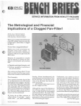
INSTALLATION GUIDE
Agilent Technologies
MPS Mainframe
Model 66000A
SERIAL NUMBERS
For mainframe with serial numbers:
Agilent Model 66000A: 3138A-00101 and above
* For instruments with higher Serial Numbers, a change page may be included.
Agilent Part No. 66000-90001
Microfiche Part No. 66000-90002
Printed in USA: June , 1997
Update April 2000
CERTIFICATION
Agilent Technologies certifies that this product met its published specifications at time of shipment from the factory. Agilent
Technologies further certifies that its calibration measurements are traceable to the United States National Bureau of
Standards, to the extent allowed by the Bureau’s calibration facility, and to the calibration facilities of other International
Standards Organization members.
WARRANTY
This Agilent Technologies hardware product is warranted against defects in material and workmanship for a period of three
years from date of delivery. Agilent Technologies software and firmware products, which are designated by Agilent
Technologies for use with a hardware product and when properly installed on that hardware product, are warranted not to
fail to execute their programming instructions due to defects in material and workmanship for a period of 90 days from date
of delivery. During the warranty period Agilent Technologies will, at its option, either repair or replace products which
prove to be defective. Agilent Technologies does not warrant that the operation of the software, firmware, or hardware shall
be uninterrupted or error free.
For warranty service, with the exception of warranty options, this product must be returned to a service facility designated
by Agilent Technologies. Customer shall prepay shipping charges by (and shall pay all duty and taxes) for products returned
to Agilent Technologies for warranty service. Except for products returned to Customer from another country, Agilent
Technologies shall pay for return of products to Customer.
Warranty services outside the country of initial purchase are included in Agilent Technologies product price, only if
Customer pays Agilent Technologies international prices (defined as destination local currency price, or U.S. or Geneva
Export price).
If Agilent Technologies is unable, within a reasonable time to repair or replace any product to condition as warranted, the
Customer shall be entitled to a refund of the purchase price upon return of the product to Agilent Technologies.
LIMITATION OF WARRANTY
The foregoing warranty shall not apply to defects resulting from improper or inadequate maintenance by the Customer,
Customer-supplied software or interfacing, unauthorized modification or misuse, operation outside of the environmental
specifications for the product, or improper site preparation and maintenance. NO OTHER WARRANTY IS EXPRESSED
OR IMPLIED. AGILENT TECHNOLOGIES SPECIFICALLY DISCLAIMS THE IMPLIED WARRANTIES OF
MERCHANTABILITY AND FITNESS FOR A PARTICULAR PURPOSE.
EXCLUSIVE REMEDIES
THE REMEDIES PROVIDED HEREIN ARE THE CUSTOMER’S SOLE AND EXCLUSIVE REMEDIES. AGILENT
TECHNOLOGIES SHALL NOT BE LIABLE FOR ANY DIRECT, INDIRECT, SPECIAL, INCIDENTAL, OR
CONSEQUENTIAL DAMAGES, WHETHER BASED ON CONTRACT, TORT, OR ANY OTHER LEGAL THEORY.
ASSISTANCE
The above statements apply only to the standard product warranty. Warranty options, extended support contracts, product
maintenance agreements and customer assistance agreements are also available. Contact your nearest Agilent
Technologies Sales and Service office for further information on Agilent Technologies’ full line of Support Programs.
2
SAFETY SUMMARY
The following general safety precautions must be observed during all phases of operation, service, and repair of this
mainframe. Failure to comply with these precautions or with specific warnings elsewhere in this guide violates safety
standards of design, manufacture, and intended use of the mainframe. Agilent Technologies assumes no liability for the
customer’s failure to comply with these requirements.
BEFORE APPLYING POWER.
Verify that the product is set to match the available line voltage and the correct fuse is installed.
GROUND THE MAINFRAME.
This product is a Safety Class 1 instrument (provided with a protective earth terminal). To minimize shock hazard, the mainframe must
be connected to an electrical ground. The mainframe must be connected to the ac power supply mains through a three-conductor power
cable, with the third wire firmly connected to an electrical ground (safety ground) at the power outlet. Any interruption of the protective
(grounding) conductor or disconnection of the protective earth terminal will cause a potential shock hazard that could result in personal
injury.
DO NOT OPERATE IN AN EXPLOSIVE ATMOSPHERE.
Do not operate the instrument in the presence of flammable gases or fumes.
KEEP AWAY FROM LIVE CIRCUITS.
Operating personnel must not remove instrument covers. Component replacement and internal adjustments must be made by qualified
service personnel. Do not replace components with power cable connected. Under certain conditions, dangerous voltages may exist even
with the power cable removed. To avoid injuries, always disconnect power, discharge circuits and remove external voltage sources before
touching components.
DO NOT SERVICE OR ADJUST ALONE.
Do not attempt internal service or adjustment unless another person, capable of rendering first aid and resuscitation, is present.
DO NOT EXCEED INPUT RATINGS.
This mainframe is equipped with a power line filter to reduce electromagnetic interference and must be connected to a properly grounded
receptacle to minimize electric shock hazard. Operation at line voltages or frequencies in excess of those stated on the line rating label
may cause leakage currents in excess of 5.0 mA peak.
SAFETY SYMBOLS.
Instruction manual symbol: the product will be marked with this symbol when it is necessary for the user to refer to the
instruction manual (refer to Table of Contents) .
Indicates hazardous voltages.
Indicates earth (ground) terminal.
The WARNING sign denotes a hazard. It calls attention to a procedure, practice, or the like, which, if not correctly
performed or adhered to, could result in personal injury. Do not proceed beyond a WARNING sign until the
indicated conditions are fully understood and met.
The CAUTION sign denotes a hazard. It calls attention to an operating procedure, or the like, which, if not correctly
performed or adhered to, could result in damage to or destruction of part or all of the product. Do not proceed
beyond a CAUTION sign until the indicated conditions are fully understood and met.
DO NOT SUBSTITUTE PARTS OR MODIFY INSTRUMENT.
Because of the danger of introducing additional hazards, do not install substitute parts or perform any unauthorized modification to the
instrument. Return the instrument to an Agilent Technologies Sales and Service Office for service and repair to ensure that safety features
are maintained.
Mainframes that appear damaged or defective should be made inoperative and secured against unintended operation until they can be
repaired by qualified service personnel.
3
SAFETY SUMMARY (continued)
GENERAL: Any LEDs used in this product are Class 1 LEDs as per IEC 825-1.
ENVIRONMENTAL CONDITIONS:
This instrument is intended for indoor use in an installation category II, pollution degree 2 environment. It is
designed to operate at a maximum relative humidity of 95% and at altitudes of up to 2000 meters. Refer to the
specifications tables for the ac mains voltage requirements and ambient operating temperature range.
SAFETY SYMBOL DEFINITIONS
Symbol
Description
Symbol
Description
Direct current
Terminal for Line conductor on permanently
installed equipment
Alternating current
Caution, risk of electric shock
Both direct and alternating current
Caution, hot surface
Three-phase alternating current
Caution (refer to accompanying documents)
Earth (ground) terminal
In position of a bi-stable push control
Protective earth (ground) terminal
Out position of a bi-stable push control
Frame or chassis terminal
On (supply)
Terminal for Neutral conductor on
permanently installed equipment
Off (supply)
Terminal is at earth potential
(Used for measurement and control
circuits designed to be operated with
one terminal at earth potential.)
Standby (supply) - Units with this symbol are not
completely disconnected from ac mains when
this switch is off. To completely disconnect the
unit from ac mains, either disconnect the power
cord or have a qualified electrician install an
external switch.
Herstellerbescheinigung
Diese Information steht im Zusammenhang mit den Anforderungen der
Maschinenläminformationsverordnung vom 18 Januar 1991.
* Schalldruckpegel Lp <70 dB(A)
* Nach EN 27779 (Typprüfung).
* Am Arbeitsplatz
* Normaler Betrieb
Manufacturer’s Declaration
This statement is provided to comply with the requirements of the German Sound Emission Directive,
from 18 January 1991.
* Sound Pressure Lp <70 dB(A) * At Operator Position
* According to EN 27779 (Type Test).
4
* Normal Operation
DECLARATION OF CONFORMITY
according to ISO/IEC Guide 22 and EN 45014
Manufacturer's Name:
Agilent Technologies, Inc.
Manufacturer's Address:
140 Green Pond Road
Rockaway, New Jersey 07866
U.S.A.
declares that the Product
Product Name:
Modular Power System mainframe and modules
Model Number:
Agilent 66000A mainframe and modules
Agilent 66101A, 66102A, 66103A, 66104A, 66105A, 66106A
conforms to the following Product Specifications:
Safety:
IEC 348:1978 / HD 401S1: 1981 1
EMC:
CISPR 11:1990 / EN 55011:1991 - Group 1 Class A
IEC 801-2:1991 / EN 50082-1:1992 - 4 kV CD, 8 kV AD
IEC 801-3:1984 / EN 50082-1:1992 - 3 V / m
IEC 801-4:1988 / EN 50082-1:1992 - 0.5 kV Signal Lines
1 kV Power Lines
Supplementary Information:
The product herewith complies with the requirements of the Low Voltage Directive
73/23/EEC and the EMC Directive 89/336/EEC and carries the CE-marking accordingly.
Note 1: The product family was introduced prior to 12/93.
New Jersey
Location
January 1997
Date
Bruce Krueger / Quality Manager
European Contact: Your local Agilent Technologies Sales and Service Office or Agilent Technologies GmbH,
Department TRE, Herrenberger Strasse 130, D-71034 Boeblingen (FAX:+49-7031-14-3143)
Printing History
The current edition of this guide is indicated below. Reprints of this guide containing minor corrections and updates may
have the same printing date. New editions are identified by a new printing date and, in some cases, by a new part number.
A new edition incorporates all new or corrected material since the previous edition. Changes to the guide occurring
between editions are covered by change sheets shipped with the guide. Also, if the serial number prefix of your mainframe
is higher than those listed on the title page of this guide, then it may or may not include a change sheet. That is because
even though the higher serial prefix indicates a design change, that change may not affect the content of the guide.
Edition 1 ... October, 1991 (Agilent Model 66000A)
Update April 2000
© Copyright 1991 Agilent Technologies, Inc.
This document contains proprietary information protected by copyright. All rights are reserved. No part of this document
may be photocopied, reproduced, or translated into another language without the prior consent of Agilent Technologies.
The information contained in this document is subject to change without notice.
5
Table Of Contents
1.
General Information
Introduction ..................................................................................................................................................9
Safety Considerations...................................................................................................................................9
Instrument Identification ..............................................................................................................................9
Options and Parts .......................................................................................................................................10
Description .................................................................................................................................................10
Specifications and Supplemental Characteristics .......................................................................................11
2.
Installation
Installation..................................................................................................................................................13
Items Supplied............................................................................................................................................13
Input Power ................................................................................................................................................13
Line Voltage Conversion.........................................................................................................................13
Fuses........................................................................................................................................................14
Power Cord Installation..............................................................................................................................14
Location and Cooling .................................................................................................................................15
Bench Operation......................................................................................................................................15
Rack Mounting ........................................................................................................................................15
Temperature Performance .......................................................................................................................15
Rear Panel Switches ...................................................................................................................................16
Address Switches .................................................................................................................................16
Frame Mode Switch ................................................................................................................................16
Module Installation.....................................................................................................................................18
Module Removal ........................................................................................................................................18
Mainframe Turn-On Checkout ...................................................................................................................19
3.
Connections
Rear Panel ..................................................................................................................................................21
Module Connections...................................................................................................................................21
Controller Connections...............................................................................................................................22
Multiple MPS Mainframes ......................................................................................................................22
MPS Mainframe/Power Supply Connections ..........................................................................................22
Keyboard Connection.................................................................................................................................22
Digital Connections ....................................................................................................................................22
Trigger Connections ...................................................................................................................................24
Index
6
..............................................................................................................................27
Figures
2-1.
2-2.
2-3.
2-4.
2-5.
3-1.
3-2.
3-3.
3-4.
Power Cord Plug Configurations............................................................................................14
Power Cord Installation ..........................................................................................................15
Rear Panel Switches ...............................................................................................................16
Switch Settings .......................................................................................................................17
Module Pull Tab .....................................................................................................................18
Rear Panel Connections..........................................................................................................21
Controller Connections...........................................................................................................23
Digital Connector ...................................................................................................................24
Examples of the Remote Inhibit Function ..............................................................................25
Tables
1-1.
Specifications and Supplemental Characteristics ............................................................................11
7
1
General Information
Introduction
This guide describes how to install the Agilent 66000A Modular Power System (MPS) Mainframe. It includes the
following information:
■
■
■
■
■
specifications and operating characteristics
connecting the power cord to the mainframe
setting the address and frame switches
installing modules in the mainframe
mainframe rear panel connections
Mainframe turn-on and checkout procedures are included with the module manual since an installed module is required to
properly check out mainframe operation. Refer to the module User’s Guide for more information.
Related Documents
Programming Guide for Agilent Series 66lxxA MPS Power Modules
Installation Guide for DC Module Connectors
User’s Guide for Agilent 66lxxA Power Modules
Service Guide for Agilent Series 66lxxA MPS Power Modules
Service Guide for Agilent 66000A Modular Power System Mainframe
Quick Reference Card for optional Agilent 66001A MPS Keyboard
Agilent 66000A Modular Power System Product Note
Agilent Part No.
5959-3362
5959-3366
5959-3360
5959-3364
66000-90003
66001-90001
5091-2497E
Safety Considerations
This mainframe is a Safety Class 1 instrument, which means that it has a protective earth terminal. That terminal must be
connected to earth ground through a power source equipped with a 3-wire ground receptacle.
Refer to the safety summary page at the beginning of this manual for general safety information. Before installation or
operation, check the mainframe and review this manual for safety markings and instructions. Safety information for specific
procedures is located at the appropriate places in this manual.
Instrument Identification
The mainframe is identified by a two-part serial number, such as 3140A-01234, on the back of the unit. The first part, or
prefix, is a number-letter combination that describes:
3140 The year and week of manufacture or last significant design change. Add 1960 to the first two
digits to determine the year. For example, 31=1991, 32=1992, etc. The last two digits specify the week
of the year (40 = the 40th week).
A
The letter indicates the country of manufacture, where A = USA.
General Information
9
Options and Parts
The following options are available with the mainframe:
Option
908
909
910
831
833
834
841
843
845
846
847
848
Description
Rack Mounting Kit
Rack Mounting Kit with handles
Extra Manual Set
Power Cords
12 AWG unterminated power cord
1.5 mm2 unterminated power cord
10 AWG unterminated power cord
20 A/250 V NEMA 6-20P plug with 12 AWG power cord
20 A/250 V JIS C8303 plug with 12 AWG power cord
16 A/220 V IEC 309 plug with 1.5 mm2 power cord
30 A/120 V L5-30P locking plug with 10 AWG power cord
16 A/220 V CEE 7/7 plug with 1.5 mm2 power cord
15 A/240 V BS 546 plug with 1.5 mm2 power cord
The following mainframe items can be ordered separately:
Part Description
Safety cover, ac input
Strain relief
Screw, strain relief
Power barrier block (Figure 2-2)
Screw, power barrier block
Serial link cable (1 meter)
Digital connector plug (Figure 3-3)
Filler panel (8 supplied)
Mainframe Installation Guide
Part Number
5040-1676
1400-1195
0515-2086
0360-2421
2470-0001
5080-2148
1252-1488
66000-40006
66000-90001
Description
The Agilent 66000 Modular Power System (MPS) is an integrated, fully programmable power system that saves rack space
and GPIB addresses, and is easy to install and use. Each Agilent 66000A MPS Mainframe can accommodate up to eight
single-slot modules. With an auxiliary mainframe connected through a serial link cable, up to sixteen single-slot modules
can be controlled from a single GPIB address. For applications requiring a broader range of power ratings, the Agilent
66000 system can be serial-linked to the Agilent 667xA, 665xA, 664xA, and 603xA series power supplies.
Modules are removed and installed through the front of the mainframe. Each module has a connector that attaches to the
back of the mainframe. With the module connector wired and attached to the mainframe, the module slides in and out of the
mainframe without disturbing the application connections.
The optional Agilent 66001A MPS Keyboard is available for controlling the Agilent 66000 Modular Power System without
having to connect it to a computer.
10 General Information
Specifications and Supplemental Characteristics
Table 1-1 lists the specifications and supplemental characteristics of the MPS mainframe. Module specifications are
included in the appropriate module User’s Guide. Specifications are warranted in the temperature range of 0 to 55 degrees
C. Supplemental characteristics are not warranted, but are descriptions of minimum, maximum, or average performance
that has been determined by design or type testing.
Table 1-1. Specifications and Supplemental Characteristics
PERFORMANCE SPECIFICATIONS
AC Input Ratings
Standard:
Frequency tolerance:
87- 132 Vac
174- 250 Vac
47 - 63 Hz
SUPPLEMENTAL CHARACTERISTICS
Maximum AC Line Current Ratings (with 8 power supply modules operating at maximum output)
100 Vac:
120 Vac:
200 Vac:
220/230 Vac:
240 Vac:
Maximum power input:
29 A rms
25 A rms
16 A rms
16 A rms
15 A rms
3200 VA; 1800 W maximum; 1600 W typical
GPIB Interface Capabilities
Languages:
IEEE 488.2 Capabilities:
Standard Commands for Programmable Instruments (see module
Programming Guide)
SH1, AH1, T6, L4, SR1, RL1, PPO, DC1, DT1, El, and CO
Serial Link Capabilities (Multiple mainframes sharing one GPIB address)
Number of mainframes:
Number of modules:
Serial-linked power supplies:
Chain length:
2
16
total number of modules and serial-linked power supplies (Agilent
667xA/665xA/664xA/603xA) cannot exceed 16
30 m (100 ft) maximum
TrigIn/TrigOut Characteristics
Maximum Ratings:
± 16.5 V between center conductor and chassis
Trig Out (HC TTL output):
VOL @ 4 ma = 1.34 V maximum
VOL @ 2 ma = 0.8 V maximum
VOH 4 ma = 2.66 V minimum
VOH 2 ma = 3.18 V minimum
Trig In (10k pull-up):
IIL @ 4 V = 700 µA
IIH @ 5.25 V = 200 µA
VIL = 0.8 V maximum
VIH = 2.0 V minimum
General Information 11
Table 1-1. Specifications and Supplemental Characteristics (continued)
INH/FLT Characteristics
Maximum Ratings:
± 16.5 V between pins 3 and 4
+ 16.5 V between pins 1 and 2
- 5.3 V between pins 1 and 2
INH (10k pull-up):
IIL @ 4 V = 700 µA
IIH @ 5.25 V = 200 µA
VIL = 0.8 V maximum
VIH = 2.0 V minimum
DFI (open collector):
VCE = 0.4 V maximum @ IC = 2.2 mA
IIH @ 5.25 V = 200 µA
VIL = 0.8 V maximum
VIH = 2.0 V minimum
Dimensions
Width:
Height:
Depth:
426 mm (16.75 in)
178 mm (7 in), add 13 mm (0.5 in) for removable feet
678 mm (26.7 in), including module connectors
Weight (does not include modules)
Net:
Shipping:
15 kg/33 lbs.
19 kg/41 lbs.
Environmental & Safety
Compliance
CSA 556B
RFI Suppression
VDE 0871.6.78 Level B
12 General Information
IEC 348 UL 1244
VDE 0411
2
Installation
Installation
When you receive your mainframe, first look for any obvious damage that could have occurred during shipment. If there is
damage, notify the carrier and the nearest Agilent Sales Office immediately. Warranty information is printed behind the
cover page of this manual.
Save the shipping carton and packing materials in case the mainframe has to be returned to Agilent Technologies in the
future. If you return the mainframe for service, attach a tag identifying the owner and model number. Also include a brief
description of the problem.
Items Supplied
In addition to this manual, check that the following items are included with the mainframe:
Power Cord
Your mainframe was shipped with a power cord for the type of outlet used at your location. Depending
on the option that was ordered, some power cords are shipped without a plug. If the appropriate cord was not included,
refer to the option list in Chapter 1 and contact your nearest Agilent Sales and Service Office to obtain the correct cord.
Your mainframe cannot use a standard power cord. The power cords listed in Chapter 1 have heavier
gauge wire.
Filler Panels
Eight filler panels are included with each mainframe. Filler panels are installed in empty module slots.
Serial Cable
A 1-meter serial cable that connects to the J1 connector next to the GPIB connector. This is used to
serially connect two mainframes or a mainframe with power supplies that have the serial-link capability on the same GPIB
address.
Keyboard
Reference
Card
A quick reference card for the optional Agilent 66001A MPS Keyboard is included with the
mainframe.
Manual
If applicable, change sheets may be included with this manual. If change sheets are included, make
Change Sheet the corrections to the manual.
Input Power
You can operate your mainframe either from a 87 - 132 Vac or a 174 - 250 Vac single phase ac power source. Refer to
Chapter 1 for complete input power specifications and requirements.
Line Voltage Conversion
The mainframe contains no line voltage switches. Refer to the module User’s Guide for information on changing the line
voltage.
Installation 13
Fuses
The mainframe fuse is located inside the mainframe. Refer to the mainframe Service Manual for information about
replacing the fuse.
Power Cord Installation
The power cord supplied with your mainframe may or may not include a power plug. Figure 2-1 shows the various power
plugs. Ring terminals are attached to one end of the power cord to facilitate mainframe installation.
Figure 2-1. Power Cord Plug Configurations
If your power cord will be directly wired into your location’s power system, installation must be done
by a qualified electrician and in accordance with local electrical codes.
To install the power cord, refer to Figure 2-2 and proceed as follows:
■
■
■
■
Position the strain relief connector, safety cover, rubber boot, and connector nut on the power cord.
Secure the ground wire to the earth ground stud.
Connect the neutral wire to the "N" input terminal.
Connect the line wire to the "L" input terminal.
Note
■
Route the power cord wires upward from the terminal block. This allows room to install the safety cover.
Replace the safety cover and tighten the cover and strain relief screws.
Do not apply power to the mainframe until directed to do so in the Check-out procedure located in the
module User’s Guide.
14 Installation
Figure 2-2. Power Cord Installation
Location and Cooling
Bench Operation
Chapter 1 gives the dimensions of your mainframe. The mainframe has plastic feet that are shaped to ensure self-alignment
when stacked with other Agilent System II cabinets. The feet may be removed for rack mounting. Your mainframe must be
installed in a location that allows sufficient space at the sides and rear of the mainframe for adequate air circulation. Do not
block the vents at the sides and rear of the mainframe.
Rack Mounting
The mainframe can be mounted in a standard 19-inch rack panel or cabinet. Refer to Chapter 1 for mainframe dimensions.
A fully loaded mainframe can weigh over 36 kg (80 lbs). Install the mainframe into the rack before installing the modules
into the mainframe.
Rack mounting kits are available as option numbers 908 and 909 (with handles). Installation instructions are included with
each rack mounting kit.
Note
Instrument support rails are also required for rack mounting. These are normally supplied with the
cabinet and are not included with the rack mounting kits.
Temperature Performance
The mainframe can operate within the temperature range of 0° to 55° C. Fans in each module cool the modules by drawing
in air through the sides of the mainframe and exhausting it out the back. Using Agilent rack mount or slide kits will not
impede the flow of air.
Installation 15
Rear Panel Switches
The six-position rear panel switch is shown in the following figure.
Figure 2-3. Rear Panel Switches
Address Switches
Address switches A0 through A4 set the primary GPIB address. The address is set in binary, A0 being the least significant
bit and A4 being the most significant bit. Figure 2-3 shows the factory-set address of "5" (binary 00101). Any address from
decimal 0 to decimal 30 is a valid GPIB address. Refer to the following diagram for switch settings.
Address
0
1
2
3
4
5
6
7
8
9
A4
0
0
0
0
0
0
0
0
0
0
Switch Positions
A3 A2 A1
0
0
0
0
0
0
0
0
1
0
0
1
0
1
0
0
1
0
0
1
1
0
1
1
1
0
0
1
0
0
Address
A0
0
1
0
1
0
1
0
1
0
1
10
11
12
13
14
15
16
17
18
19
A4
0
0
0
0
0
0
1
1
1
1
Switch Positions
A3 A2 A1
1
0
1
1
0
1
1
1
0
1
1
0
1
1
1
1
1
1
0
0
0
0
0
0
0
0
1
0
0
1
Address
A0
0
1
0
1
0
1
0
1
0
1
20
21
22
23
24
25
26
27
28
29
30
A4
1
1
1
1
1
1
1
1
1
1
1
Switch Positions
A3 A2 A1
0
1
0
0
1
0
0
1
1
0
1
1
1
0
0
1
0
0
1
0
1
1
0
1
1
1
0
1
1
0
1
1
1
Frame Mode Switch
The frame mode switch determines the IEEE 488 secondary addresses (also referred to as subaddresses) of the modules that
are installed in the mainframe. The frame mode switch must be set to MAIN when the mainframe is connected directly to
the GPIB. With the frame mode switch set to MAIN, modules are assigned secondary addresses of 0 to 7, which
corresponds to the slot locations indicated on the mainframe.
The frame mode switch must be set to AUX (auxiliary) when the mainframe is serially-linked to another mainframe that is
directly connected to the GPIB. This also applies when the mainframe is serially linked to an Agilent 603xA/664xA/665xA/
667xA power supply that is directly connected to the GPIB.
In mainframes that have the frame mode switch set to AUX, modules are assigned secondary addresses of 8 to 15.
Secondary address 8 corresponds to slot location 0 on the mainframe and secondary address 15 corresponds to slot location
7 on the mainframe as shown in the following diagram.
16 Installation
A0
0
1
0
1
0
1
0
1
0
1
0
Slot Location
Secondary Address
Note
Mainframe Slot Locations/Addresses
Mainframe Mode
Switch = MAIN
0
1
2
3
4
5
6
7
0
0
1
2
3
4
5
6
7
8
1
9
Mainframe Mode
Switch = AUX
2
3
4
5
6
10 11 12 13 14
7
15
Secondary addresses are reserved for the mainframe whether modules occupy the associated slot locations
or not.
You may want to apply stick-on labels over the slot locations of the mainframe to indicate that the modules installed in the
auxiliary mainframe are at secondary addresses 8 to 15. You may also label the modules according to their slot locations.
If any modules are removed, they can then be reinstalled in the same slot.
Figure 2-4 illustrates the relationship of the switch settings and secondary addresses. Refer to Chapter 3 for connection
information.
Figure 2-4. Switch Settings
Installation 17
Module Installation
Note
A fully loaded mainframe can weigh over 36 kg (80 lbs). Install the mainframe into the rack before
installing the modules into the mainframe.
All modules install through the front of the mainframe. Installation (and removal) can be accomplished even when the
mainframe is rack-mounted. To install the modules in the mainframe, refer to Figure 2-5 and proceed as follows:
■
■
■
■
Use a flat-bladed screwdriver and release the pull tab by pressing down.
Extend the pull tab from the module so that the serial number is visible.
Slide the module into the slot until it is fully inserted in the mainframe.
Push the pull tab into the front of the module. The slot number should be visible below the pull tab.
Note
■
■
If the module is not fully inserted in the mainframe, the pull tab will not retract into the module.
Install filler panels in the front of any unused mainframe slots.
Install the module connectors on the back of the mainframe.
Note
Instructions for wiring and installing module connectors are included with each module.
Figure 2-5. Module Pull Tab
Module Removal
All modules are removed through the front of the mainframe. Modules may be removed even when the mainframe is turned
on.
18 Installation
■
There must be no or minimal current flowing through the connector pins at the back of the module
that is being removed. This can be accomplished by disabling the module. If this precaution is
repeatedly violated at high current, the connector pins at the back of the module
will be damaged.
■
There must be no activity on the GPIB bus, the trigger connectors, or the FLT/INH connector of
the mainframe when a module is removed. This can be accomplished by not generating any GPIB
or FLT/INH activity, and by setting all modules to the trigger idle state (refer to the module
Programming Guide). If this precaution is violated, GPIB commands to other modules may be
corrupted, trigger or FLT/INH data may be lost, or an inadvertent trigger may be generated in
another module.
To remove the module from the mainframe, proceed as follows:
■
■
Use a flat-bladed screwdriver and release the pull tab by pressing down (see Figure 2-5).
Grasp the pull tab and pull the module out of the mainframe.
Note
The module connector remains attached to the mainframe after the module has been removed.
Mainframe Turn-On Checkout
The turn-on checkout procedures that verify module operation also verify the operation of the MPS mainframe. You cannot
verify the operation of the mainframe without having at least one installed module. The module self-test sequence checks
the following mainframe functions:
■
■
■
mainframe microprocessor
GPIB interface
module/mainframe communications link
Refer to the module User’s Guide for complete information on the turn-on checkout procedure.
Installation 19
3
Connections
Rear Panel
Figure 3-1 shows where all of the rear panel connections to the mainframe are made.
Figure 3-1. Rear Panel Connections
Module Connections
Wire connections to the modules are made using a separate module connector that is supplied with each module. After the
module connector has been wired, it simply attaches to the back of the mainframe. You can attach the module connector to
the mainframe either before or after the module is installed. Instructions for wiring and attaching the connector are provided
with each module.
Note
Install the module connectors from left to right on the back of the mainframe. This makes it easier to
access the screws that attach the connectors to the mainframe.
Connections 21
Controller Connections
If you have only one MPS mainframe in your system, simply connect it to the controller using the GPIB cable. If you have
more than one mainframe, or if you also have an Agilent 667xA, 665xA, 664xA, or 603xA power supply in your system,
you can use the serial-link cable supplied with your mainframe to facilitate connections. Figure 3-2 illustrates the serial-link
connections.
Multiple MPS Mainframes
See Figure 3-2. Up to 16 modules may be controlled from a primary GPIB bus address by linking two mainframes.
■
The first mainframe in a linked configuration is directly connected to the controller via a GPIB cable. The frame mode
switch on the back of this mainframe is set to "MAIN". The first mainframe has a unique primary GPIB address and
the modules in this mainframe use secondary addresses (also referred to as subaddresses) 0 through 7.
■
The second or "linked" mainframe, connects to the first mainframe with the serial-link cable. The frame mode switch
on the back of this mainframe is set to "AUX". The second mainframe uses the same primary address as the first
mainframe, but the modules in the second mainframe use secondary addresses 8 through 15.
MPS Mainframe/Power Supply Connections
See Figure 3-2b. Only one mainframe can be serially linked to a system that includes Agilent 667xA, 665xA, 664xA, or
603xA power supplies. Because the mainframe has only one serial-link jack, it can be either linked at the beginning or at
the end of a power supply serial link system.
■
At the beginning of the serial link system, the mainframe is directly connected to the controller via the GPIB cable.
The frame mode switch on the back of this mainframe is set to "MAIN". The mainframe has a unique primary GPIB
address and the modules in this mainframe use secondary addresses (also referred to as subaddresses) 0 through 7. All
power supplies serially linked to the mainframe use the same primary GPIB address, but must use secondary addresses
8 through 15.
■
At the end of the serial link system, the mainframe is linked to the last power supply in the system with the serial-link
cable. The frame mode switch on the back of this mainframe is set to "AUX". The mainframe uses the same primary
GPIB address as the power supplies and the modules in this mainframe use secondary addresses 8 through 15. In this
configuration, you can have up to eight power supplies at secondary addresses 0 through 7 ahead of the mainframe.
Keyboard Connection
The optional Agilent 66001A MPS Keyboard connects to the mainframe through the keyboard jack located at the front of
the mainframe and at the back of the mainframe as shown in Figure 3-1. More information on using the keyboard can be
found in the module User’s Guide.
Digital Connections
A 4-pin connector and a quick-disconnect mating plug provide a discrete fault indicator (FLT) output and a remote inhibit
(INH) input (see Figure 3-3). Disconnect the mating plug to make your wire connections. The electrical characteristics of
the FLT output and the INH input are described in Chapter 1. More information on using digital connectors can be found in
Chapter 4 of the module User’s Guide under "RI Function" and "DFI Function".
22 Connections
Figure 3-2. Controller Connections
Connections 23
Figure 3-3. Digital Connector
FLT Output
(pins 1 and 2)
Used to indicate that a fault has occurred on one of the modules in the mainframe. Pins 1 and 2
are the open-collector output of an optocoupler, with pin 1 the collector and pin 2 the emitter. When a
fault has occurred, pin 1 is driven low with respect to pin 2 (negative-true).
INH Input
(pin 3)
Used to shut down the outputs of all modules in the mainframe that have been enabled to respond to
the remote inhibit function. Pin 3 is a high impedance input. The inhibit function is activated when this
input is driven low (negative-true). This can be accomplished by shorting pin 3 to pin 4.
INH Common
(pin 4)
Provides the common connection for the INH input.
After you have finished making all wire connections, replace the mating plug in the connector.
Figure 3-4 shows two simple applications for the INH input. The first is a "panic switch" that applies the INH input signal
to both mainframes, which shuts down the modules simultaneously in both mainframes. The second application uses the
INH input signal to shut down modules in the main mainframe. In this case, the modules in the main mainframe must be
programmed to generate an FLT signal upon receipt of the INH signal. The FLT signal generated by the modules in the
main mainframe is then applied to the RI input of the auxiliary mainframe.
Note
Software control of the RI function is described further in Chapter 5 of the module Programming Guide.
Trigger Connections
Trigger connections are made to the BNC connectors on the rear panel as shown in Figure 3-1. The electrical
characteristics of the trigger connectors are described in Chapter 1. More information on the capabilities of the external
triggers can be found in Chapter 5 of the module Programming Guide.
Trigger IN
Allows negative-going external trigger signals to trigger one or more modules in the mainframe.
Trigger OUT
Provides a negative-going wired-ORed pulse that indicates a trigger has occurred on one or more of the
modules in the mainframe.
24 Connections
Figure 3-4. Examples of the Remote Inhibit Function
Connections 25
Index
A
addresses, 16
address switch, 16
Agilent 603xA, 10, 11, 16, 22
Agilent 664xA, 10, 11, 16, 22
Agilent 665xA, 10, 11, 16, 22
Agilent 667xA, 10, 11, 16, 22
AUX, 16, 17, 22
B
BNC connectors, 24
C
characteristics, 11
connector, 18, 19, 21
connector - installation, 21
D
digital connector plug, 10, 22, 24
documentation, 9
F
feet, 15
filler panel, 10, 13, 18
FLT/INH, 12, 24
frame mode, 17, 22
frame switch, 16, 22
fuses, 14
H
GPIB address, 16, 22
GPIB interface, 11
K
keyboard, 22
L
line current, 11
line voltage, 11, 13
line voltage, changing, 13
M
MAIN, 16, 22
manuals, 9, 13
module, 11, 21, 22
module - addresses, 22
module - connector, 21
module - installation, 18
module - removal, 18-19
modules, 11, 18
O
options, 10
P
parts, 10
power cord, 10, 13, 14
power cord – installation, 14
power plug, 10, 14
primary address, 22
pull tab, 18, 19
R
rack mounting, 15
S
safety cover, 14
screws, 10
secondary address, 16, 22
serial cable, 10, 13, 22
serial-link, 22
serial number, 18
slot address, 16, 17, 18
specifications, 11
strain relief, 14, 15
support rails, 15
switches, 16
T
temperature range, 15
terminal block, 14
trigger - connections, 24
Trigln/TrigOut, 11, 24
W
warranty, 13
Index 27
Agilent Sales and Support Offices
For more information about Agilent Technologies test and measurement products, applications, services,
and for a current sales office listing, visit our web site: http://www.agilent.com/find/tmdir
You can also contact one of the following centers and ask for a test and measurement sales
representative.
United States:
Agilent Technologies
Test and Measurement Call Center
P.O. Box 4026
Englewood, CO 80155-4026
(tel) 1 800 452 4844
Latin America:
Agilent Technologies
Latin American Region Headquarters
5200 Blue Lagoon Drive, Suite #950
Miami, Florida 33126
U.S.A.
(tel) (305) 267 4245
(fax) (305) 267 4286
Canada:
Agilent Technologies Canada Inc.
5150 Spectrum Way
Mississauga, Ontario
L4W 5G1
(tel) 1 877 894 4414
Australia/New Zealand:
Agilent Technologies Australia Pty Ltd
347 Burwood Highway
Forest Hill, Victoria 3131
(tel) 1-800 629 485 (Australia)
(fax) (61 3) 9272 0749
(tel) 0 800 738 378 (New Zealand)
(fax) (64 4) 802 6881
Europe:
Agilent Technologies
Test & Measurement European Marketing Organisation
P.O. Box 999
1180 AZ Amstelveen
The Netherlands
(tel) (31 20) 547 9999
Asia Pacific:
Agilent Technologies
24/F, Cityplaza One, 1111 King’s Road,
Taikoo Shing, Hong Kong
tel: (852)-3197-7777
fax: (852)-2506-9284
Japan:
Agilent Technologies Japan Ltd.
Measurement Assistance Center
9-1, Takakura-Cho, Hachioji-Shi,
Tokyo 192-8510, Japan
(tel) (81) 426 56 7832
(fax) (81) 426 56 7840
Technical data is subject to change.
Manual Updates
The following updates have been made to this manual since the print revision indicated on the title page.
4/15/00
All references to HP have been changed to Agilent.
All references to HP-IB have been changed to GPIB.