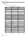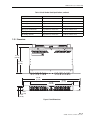
1
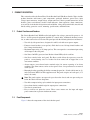
ADCP-80-570
Issue 2
March 2006
PowerWorx® Power Distribution Products
Circuit Breaker Panel With Reset Switch
User Manual
20629-A
1361499 Rev A
ADCP-80-570 • Issue 2 • March 2006 • Preface
COPYRIGHT
© 2006, ADC Telecommunications, Inc.
All Rights Reserved
Printed in the U.S.A.
REVISION HISTORY
ISSUE
DATE
1
8/2005
REASON FOR CHANGE
Original.
2
3/2006
Wire colors corrected on Page 28.
TRADEMARK INFORMATION
ADC and PowerWorx are registered trademarks of ADC Telecommunications, Inc.
DISCLAIMER OF LIABILITY
Contents herein are current as of the date of publication. ADC reserves the right to change the contents without prior notice. In no
event shall ADC be liable for any damages resulting from loss of data, loss of use, or loss of profits and ADC further
disclaims any and all liability for indirect, incidental, special, consequential or other similar damages. This disclaimer of
liability applies to all products, publications and services during and after the warranty period.
This publication may be verified at any time by contacting ADC’s Technical Assistance Center at 1-800-366-3891, extension 73475
(in U.S.A. or Canada) or 952-917-3475 (outside U.S.A. and Canada), or by e-mail to [email protected].
ADC Telecommunications, Inc.
P.O. Box 1101, Minneapolis, Minnesota 55440-1101
In U.S.A. and Canada: 1-800-366-3891
Outside U.S.A. and Canada: (952) 938-8080
Fax: (952) 917-1717
Page ii
ADCP-80-570 • Issue 2 • March 2006 • Preface
TABLE OF CONTENTS
Content
Page
About This Manual . . . . . . . . . . . . . . . . . . . . . . . . . . . . . . . . . . . . . . . . . . . . . . . . . . . . . . . . . . . . . . . . . . . . . . . . . . . v
Standard Certification . . . . . . . . . . . . . . . . . . . . . . . . . . . . . . . . . . . . . . . . . . . . . . . . . . . . . . . . . . . . . . . . . . . . . . . . . v
Admonishments . . . . . . . . . . . . . . . . . . . . . . . . . . . . . . . . . . . . . . . . . . . . . . . . . . . . . . . . . . . . . . . . . . . . . . . . . . . . . v
General Safety Precautions . . . . . . . . . . . . . . . . . . . . . . . . . . . . . . . . . . . . . . . . . . . . . . . . . . . . . . . . . . . . . . . . . . . . . v
List of Acronyms . . . . . . . . . . . . . . . . . . . . . . . . . . . . . . . . . . . . . . . . . . . . . . . . . . . . . . . . . . . . . . . . . . . . . . . . . . . . .vi
1
PRODUCT DESCRIPTION . . . . . . . . . . . . . . . . . . . . . . . . . . . . . . . . . . . . . . . . . . . . . . . . . . . . . . . . . . . . . . . . . . 1
1.1
Product Functions and Features. . . . . . . . . . . . . . . . . . . . . . . . . . . . . . . . . . . . . . . . . . . . . . . . . . . . . . . . 1
1.2
Panel Components. . . . . . . . . . . . . . . . . . . . . . . . . . . . . . . . . . . . . . . . . . . . . . . . . . . . . . . . . . . . . . . . . 1
1.3
Packaged Hardware . . . . . . . . . . . . . . . . . . . . . . . . . . . . . . . . . . . . . . . . . . . . . . . . . . . . . . . . . . . . . . . . 3
1.4
Power Buses . . . . . . . . . . . . . . . . . . . . . . . . . . . . . . . . . . . . . . . . . . . . . . . . . . . . . . . . . . . . . . . . . . . . . 4
1.5
Input Voltage . . . . . . . . . . . . . . . . . . . . . . . . . . . . . . . . . . . . . . . . . . . . . . . . . . . . . . . . . . . . . . . . . . . . 5
1.6
Input Connectors . . . . . . . . . . . . . . . . . . . . . . . . . . . . . . . . . . . . . . . . . . . . . . . . . . . . . . . . . . . . . . . . . . 5
1.7
Output Voltage . . . . . . . . . . . . . . . . . . . . . . . . . . . . . . . . . . . . . . . . . . . . . . . . . . . . . . . . . . . . . . . . . . . 5
1.8
Output Connectors . . . . . . . . . . . . . . . . . . . . . . . . . . . . . . . . . . . . . . . . . . . . . . . . . . . . . . . . . . . . . . . . . 5
1.9
Chassis Ground Connections . . . . . . . . . . . . . . . . . . . . . . . . . . . . . . . . . . . . . . . . . . . . . . . . . . . . . . . . . . 6
1.10 Circuit Breakers . . . . . . . . . . . . . . . . . . . . . . . . . . . . . . . . . . . . . . . . . . . . . . . . . . . . . . . . . . . . . . . . . . 6
1.11 Power-on Indicators . . . . . . . . . . . . . . . . . . . . . . . . . . . . . . . . . . . . . . . . . . . . . . . . . . . . . . . . . . . . . . . . 6
1.12 Breaker Alarm Indicators . . . . . . . . . . . . . . . . . . . . . . . . . . . . . . . . . . . . . . . . . . . . . . . . . . . . . . . . . . . . 7
1.13 Alarm Operation . . . . . . . . . . . . . . . . . . . . . . . . . . . . . . . . . . . . . . . . . . . . . . . . . . . . . . . . . . . . . . . . . . 7
1.14 Alarm Connections . . . . . . . . . . . . . . . . . . . . . . . . . . . . . . . . . . . . . . . . . . . . . . . . . . . . . . . . . . . . . . . . 7
1.15 Reset Switch. . . . . . . . . . . . . . . . . . . . . . . . . . . . . . . . . . . . . . . . . . . . . . . . . . . . . . . . . . . . . . . . . . . . . 7
1.16 Circuit Breaker Designation Card and Holder. . . . . . . . . . . . . . . . . . . . . . . . . . . . . . . . . . . . . . . . . . . . . . . 7
1.17 Voltage Designation Label . . . . . . . . . . . . . . . . . . . . . . . . . . . . . . . . . . . . . . . . . . . . . . . . . . . . . . . . . . . 8
1.18 Material and Finish . . . . . . . . . . . . . . . . . . . . . . . . . . . . . . . . . . . . . . . . . . . . . . . . . . . . . . . . . . . . . . . . 8
1.19 Cooling . . . . . . . . . . . . . . . . . . . . . . . . . . . . . . . . . . . . . . . . . . . . . . . . . . . . . . . . . . . . . . . . . . . . . . . . 8
1.20 Protective Covers . . . . . . . . . . . . . . . . . . . . . . . . . . . . . . . . . . . . . . . . . . . . . . . . . . . . . . . . . . . . . . . . . 9
1.21 Mounting . . . . . . . . . . . . . . . . . . . . . . . . . . . . . . . . . . . . . . . . . . . . . . . . . . . . . . . . . . . . . . . . . . . . . . . 9
1.22 Specifications . . . . . . . . . . . . . . . . . . . . . . . . . . . . . . . . . . . . . . . . . . . . . . . . . . . . . . . . . . . . . . . . . . . 10
1.23 Dimensions . . . . . . . . . . . . . . . . . . . . . . . . . . . . . . . . . . . . . . . . . . . . . . . . . . . . . . . . . . . . . . . . . . . . 11
2
ACCESSORIES . . . . . . . . . . . . . . . . . . . . . . . . . . . . . . . . . . . . . . . . . . . . . . . . . . . . . . . . . . . . . . . . . . . . . . . . 12
3
UNPACKING AND INSPECTION . . . . . . . . . . . . . . . . . . . . . . . . . . . . . . . . . . . . . . . . . . . . . . . . . . . . . . . . . . . . . 12
4
INSTALLATION . . . . . . . . . . . . . . . . . . . . . . . . . . . . . . . . . . . . . . . . . . . . . . . . . . . . . . . . . . . . . . . . . . . . . . . . 12
4.1
Installation Tools Required . . . . . . . . . . . . . . . . . . . . . . . . . . . . . . . . . . . . . . . . . . . . . . . . . . . . . . . . . . 13
4.2
Materials Required . . . . . . . . . . . . . . . . . . . . . . . . . . . . . . . . . . . . . . . . . . . . . . . . . . . . . . . . . . . . . . . 13
4.3
Pre-Installation Testing . . . . . . . . . . . . . . . . . . . . . . . . . . . . . . . . . . . . . . . . . . . . . . . . . . . . . . . . . . . . 13
4.4
Cable Management Bar (Optional Accessory) . . . . . . . . . . . . . . . . . . . . . . . . . . . . . . . . . . . . . . . . . . . . . 16
4.5
Mounting Panel on Rack . . . . . . . . . . . . . . . . . . . . . . . . . . . . . . . . . . . . . . . . . . . . . . . . . . . . . . . . . . . . 16
4.6
Installing Designation Cards . . . . . . . . . . . . . . . . . . . . . . . . . . . . . . . . . . . . . . . . . . . . . . . . . . . . . . . . . 18
4.7
Installing Voltage Designation Label . . . . . . . . . . . . . . . . . . . . . . . . . . . . . . . . . . . . . . . . . . . . . . . . . . . 18
4.8
Installing Ground Wires . . . . . . . . . . . . . . . . . . . . . . . . . . . . . . . . . . . . . . . . . . . . . . . . . . . . . . . . . . . . 18
4.9
Connecting Alarms . . . . . . . . . . . . . . . . . . . . . . . . . . . . . . . . . . . . . . . . . . . . . . . . . . . . . . . . . . . . . . . 19
Page iii
© 2006, ADC Telecommunications, Inc.
ADCP-80-570 • Issue 2 • March 2006 • Preface
TABLE OF CONTENTS
Content
Page
4.10 Connecting Output. . . . . . . . . . . . . . . . . . . . . . . . . . . . . . . . . . . . . . . . . . . . . . . . . . . . . . . . . . . . . . . . 20
4.11 Connecting Input. . . . . . . . . . . . . . . . . . . . . . . . . . . . . . . . . . . . . . . . . . . . . . . . . . . . . . . . . . . . . . . . . 21
4.12 Installing Protective Covers . . . . . . . . . . . . . . . . . . . . . . . . . . . . . . . . . . . . . . . . . . . . . . . . . . . . . . . . . 23
5
6
7
TESTING . . . . . . . . . . . . . . . . . . . . . . . . . . . . . . . . . . . . . . . . . . . . . . . . . . . . . . . . . . . . . . . . . . . . . . . . . . . . 24
5.1
Testing Power Indicators and Connection Polarity . . . . . . . . . . . . . . . . . . . . . . . . . . . . . . . . . . . . . . . . . . 24
5.2
Testing Alarm Contacts Normal State . . . . . . . . . . . . . . . . . . . . . . . . . . . . . . . . . . . . . . . . . . . . . . . . . . . 24
OPERATION . . . . . . . . . . . . . . . . . . . . . . . . . . . . . . . . . . . . . . . . . . . . . . . . . . . . . . . . . . . . . . . . . . . . . . . . . . 25
6.1
Connecting New Equipment . . . . . . . . . . . . . . . . . . . . . . . . . . . . . . . . . . . . . . . . . . . . . . . . . . . . . . . . . 25
6.2
Using the Reset Switch . . . . . . . . . . . . . . . . . . . . . . . . . . . . . . . . . . . . . . . . . . . . . . . . . . . . . . . . . . . . 26
MAINTENANCE . . . . . . . . . . . . . . . . . . . . . . . . . . . . . . . . . . . . . . . . . . . . . . . . . . . . . . . . . . . . . . . . . . . . . . . . 26
7.1
Performing a Routine Inspection . . . . . . . . . . . . . . . . . . . . . . . . . . . . . . . . . . . . . . . . . . . . . . . . . . . . . . 26
7.2
Replacing a Circuit Breaker . . . . . . . . . . . . . . . . . . . . . . . . . . . . . . . . . . . . . . . . . . . . . . . . . . . . . . . . . 26
8
CUSTOMER INFORMATION AND ASSISTANCE. . . . . . . . . . . . . . . . . . . . . . . . . . . . . . . . . . . . . . . . . . . . . . . . . . . 29
A
ALLOWABLE AMPACITIES OF INSULATED CONDUCTORS . . . . . . . . . . . . . . . . . . . . . . . . . . . . . . . . . . . . . . . . . . . 31
Page iv
© 2006, ADC Telecommunications, Inc.
ADCP-80-570 • Issue 2 • March 2006 • Preface
ABOUT THIS MANUAL
This manual describes the PowerWorx Circuit Breaker Panel With Reset Switch, and provides
all information required to install, test, and operate this product.
STANDARD CERTIFICATION
The panel conforms to the applicable requirements of the following: UL/CSA/EN 60950, FCC
Part 15, CISPR 22, and CISPR 24.
ADMONISHMENTS
Important safety admonishments are used throughout this manual to warn of possible hazards to
persons or equipment. An admonishment identifies a possible hazard and then explains what
may happen if the hazard is not avoided. The admonishments — in the form of Dangers,
Warnings, and Cautions — must be followed at all times. These warnings are flagged by use of
the triangular alert icon (seen below), and are listed in descending order of severity of injury or
damage and likelihood of occurrence.
Danger: Danger is used to indicate the presence of a hazard that will cause severe personal
injury, death, or substantial property damage if the hazard is not avoided.
Warning: Warning is used to indicate the presence of a hazard that can cause severe personal
injury, death, or substantial property damage if the hazard is not avoided.
Caution: Caution is used to indicate the presence of a hazard that will or can cause minor
personal injury or property damage if the hazard is not avoided.
GENERAL SAFETY PRECAUTIONS
-
Warning: The circuit breaker panel uses electrical voltage and current levels that may be
considered an energy hazard. Only qualified personnel should be allowed to install, operate,
maintain, or otherwise come into contact with this equipment when energized. Only insulated
tools should be used on energized elements of the panel.
Warning: Disconnect or turn off the power before connecting the input or output wires on the
circuit breaker panel. This may require turning off the system office battery input at the battery
distribution fuse bay or turning off the circuit breakers at the panel.
Warning: Wet conditions increase the potential for receiving an electrical shock when
installing or using electrically-powered equipment. To prevent electrical shock, never install or
use electrical equipment in a wet location or during a lightning storm.
Page v
© 2006, ADC Telecommunications, Inc.
ADCP-80-570 • Issue 2 • March 2006 • Preface
Warning: To prevent the system from overheating, do not operate it in an area that
exceeds the maximum recommended ambient temperature of 55º C.
Warning: Stability hazard. The rack stabilizing mechanism must be in place, or the
rack must be bolted to the floor before you slide the unit out for servicing. Failure to
stabilize the rack can cause the rack to tip over.
Warning: Suitable for mounting on concrete or other non-combustible surface only.
Warning: Take care when connecting units to the supply circuit so that wiring is not
overloaded.
LIST OF ACRONYMS
LED -- Light-Emitting Diode
Page vi
© 2006, ADC Telecommunications, Inc.
ADCP-80-570 • Issue 2 • March 2006
1
PRODUCT DESCRIPTION
This section describes the PowerWorx Circuit Breaker Panel With Reset Switch. Topics include
product functions and features, panel components, packaged hardware, power buses, input
voltage, input connectors, output voltage, output connectors, chassis ground connections, circuit
breakers, power on indicators, breaker alarm indicators, alarm operation, alarm connections,
reset switch, circuit breaker designation card and holder, voltage designation label, material and
finish, cooling, protective covers, mounting, specifications, and dimensions.
1.1
Product Functions and Features
The Circuit Breaker Panel With Reset Switch supplies low-voltage, protected dc power to –24
Vdc or –48 Vdc powered equipment installed in a central office, multimedia headend, remote
site, or other restricted access location. The panel provides the following functions and features:
• Two side-by-side power buses, designated A and B, each with seven power outputs.
• Fourteen circuit breakers (seven per bus). Each bus has two 10 Amp circuit breakers and
five 5 Amp circuit breakers.
• Maximum input rating of 45 Amps per bus. This corresponds to a maximum input rating
of 90 Amps for the total panel.
• One Power On LED (green) and one Breaker Alarm LED (red) for each bus.
• One Reset switch for the total panel. The Reset switch allows the operator to reset the
panel to a non-alarming state if a breaker has been turned off or tripped due to an
overcurrent condition.
• Alarm contacts (screw-down barrier terminal strips) for remote reporting of an alarm
condition. The alarm contacts can be used to open or close a loop connected to an external
alarm system.
• Mounting brackets providing the ability to mount the panel in a 19-inch (482.6 mm) or 23inch (584.2 mm) WECO or EIA equipment rack. The panel occupies one rack space (1.75
inches, 44.4 mm).
Note: The panel requires one open rack space above the chassis and one open rack space
below the chassis for heat dissipation.
•
•
•
•
1.2
Two-hole compression-lug style terminals for input power connections.
Screw-down barrier terminal strips for output power connections.
Two chassis ground studs.
Easy to remove rear protective covers. These covers mount over the input and output
power connections to prevent inadvertent contact.
Panel Components
Figure 1 shows the components of the circuit breaker panel.
Page 1
© 2006, ADC Telecommunications, Inc.
ADCP-80-570 • Issue 2 • March 2006
BUS A
1 TO 7 CIRCUIT BREAKERS
BUS A
POWER-ON
INDICATOR
(GREEN LED)
RESET
SWITCH
BUS A ALARM
INDICATOR (RED LED)
BUS B
POWER-ON
INDICATOR
(GREEN LED)
BUS B
1 TO 7 CIRCUIT BREAKERS
FRONT VIEW
BUS B ALARM
INDICATOR (RED LED)
DESIGNATION CARD
AND CARD HOLDER
BUS B INPUT
POWER TERMINALS
ALARM
TERMINALS
BUS B OUTPUT
POWER TERMINALS
BUS A OUTPUT
POWER TERMINALS
CHASSIS
GROUNDING
STUDS
BUS A INPUT
POWER TERMINALS
COVER FOR
INPUT POWER
TERMINALS
COVER FOR
OUTPUT POWER
TERMINALS
REAR VIEW
COVER FOR
INPUT POWER
TERMINALS
Figure 1. Circuit Breaker Panel Components
Page 2
© 2006, ADC Telecommunications, Inc.
20631-A
ADCP-80-570 • Issue 2 • March 2006
1.3
Packaged Hardware
The shipped product includes hardware components that are packaged separately and shipped in
the carton with the basic panel. Figure 2 shows the shipped items:
• 5/16-inch long, Phillips drive, 8-32 flat-head screws (8)—Used to secure the mounting
brackets to the panel.
• 3/8-inch long, combination drive, 12-24 pan-head screws (4) and #12 flat washers (4)—
Used to secure the panel mounting brackets to the equipment rack.
• #10 ring terminals (2) for #12–#10 AWG wire—Can be used to connect the grounding
cables to the grounding studs.
• 2-Hole Lugs for #6 AWG wire (4)—Used to connect input power cable to input power
terminal blocks.
REAR COVER FOR OUTPUT
POWER/ALARM TERMINAL BLOCK
2-HOLE LUGS FOR
6 AWG WIRE
REAR COVERS FOR INPUT
POWER TERMINAL BLOCK
#10 RING TERMINALS FOR
12-10 AWG WIRE
5/16-INCH (7.936 MM) 8-32
FLAT-HEAD SCREWS
VOLTAGE
LABEL
ORIENTATION FOR
19-INCH RACK INSTALLATION
3/8-INCH (9.525 MM) 12-24
SCREWS AND #12 WASHERS
ORIENTATION FOR
23-INCH RACK INSTALLATION
DESIGNATION CARD
AND CARD HOLDER
UNIVERSAL MOUNTING BRACKETS
AND SCREWS
20633-A
Figure 2. Packaged Hardware
Page 3
© 2006, ADC Telecommunications, Inc.
ADCP-80-570 • Issue 2 • March 2006
• Rear protective input terminal covers (2) and output/alarm terminal cover (1)—Used to
prevent accidental contact with the alarm and power terminals.
• #6-32 Screws (4)—Used to fasten output/alarm terminal cover to rear of panel chassis.
• Designation card and card holder (1)—Used to record information about the protected
equipment. Cards and clear cover insert into the card holder.
• Voltage label (1)—Used to indicate whether the input voltage is –48 or –24 Vdc.
1.4
Power Buses
Each circuit breaker panel has two isolated power buses. Each bus distributes the input power to
the output power circuits. In each bus circuit, current flows from the input power bus, through
the circuit breaker, to the output power circuit. The current capacity of each bus is 45 Amps
maximum. Figure 3 is a block diagram of the power buses.
–24V/–48V
BATTERY
BATTERY A
RETURN
1
2
3
4
5
6
7
RETURN A
BUS A
C
NO
FA
NC
POWER A LED
BREAKER
ALARM A LED
RETURN A
FB
POWER B LED
BREAKER ALARM B LED
RETURN B
ALARM RESET PUSHBUTTON
BATTERY B
RETURN B
BATTERY
RETURN
1
2
3
4
5
6
7
20691-A
Figure 3. Circuit Breaker Panel Block Diagram
Page 4
© 2006, ADC Telecommunications, Inc.
C
NO
NC
BUS B
–24V/–48V
SYSTEM ALARM
CONNECTIONS
ADCP-80-570 • Issue 2 • March 2006
Each of the power buses supports seven circuit breaker positions including two 10 Amp circuit
breaker positions and five 5 Amp circuit breaker positions giving a total capacity per bus of 45
Amps.
When a circuit breaker trips, the input power bus is disconnected from the corresponding output
circuit.
1.5
Input Voltage
The dual bus circuit breaker panel can accommodate either –24 Vdc on both buses or –48 Vdc on
both buses.
Warning: Use of one bus only on a dual bus panel will result in false alarms for the unused bus.
Power is required on both buses on a dual bus panel for normal operation.
The voltage level is sensed by the circuit breaker panel circuitry. The input voltages used with
the circuit breaker panel can fall within the following ranges:
• –24 Vdc nominal, within range of –21 Vdc to –30 Vdc
• –48 Vdc nominal, within range of –42 Vdc to –56 Vdc
1.6
Input Connectors
Each power bus has two input connectors on the rear of the circuit breaker panel through which
input power is provided. The two input power connectors are labeled “BATT” (battery) and “RTN”
(return). Each input connector consists of a pair of 0.25-inch (0.635 cm) studs (with nuts) mounted
on a plastic terminal block. Each pair of studs can accept different size 2-hole compression lugs used
with a range of wire sizes up to #6 AWG copper wire. Two 2-hole lugs per bus for use with #6 AWG
wire (four total) are provided with the circuit breaker panel. Additional lugs are available as
accessory items. Maximum lug width is 0.62 inches (1.6 cm). In selecting the copper wire size to be
used for power input, consider the allowable ampacity as defined by local practice and the National
Electrical Code (refer to Appendix A).
1.7
Output Voltage
The output voltage will be the same as the applied input voltage.
1.8
Output Connectors
Each bus has two screw-down terminal strips with seven 8-32 screws each on the back of the
panel. The upper terminal strip contains the BATT (power feed) connectors. The lower terminal
strip contains the RTN (return) connectors. When a piece of equipment is connected to the
circuit breaker panel, it is connected to one BATT connector and one RTN connector located
vertically above and below one another.
Page 5
© 2006, ADC Telecommunications, Inc.
ADCP-80-570 • Issue 2 • March 2006
The individual terminals are on 0.375 inch (9.525 mm) centers with a distance between barriers
of 0.32 inch (81.3 mm). The terminals can accept a variety of wire sizes up to #12 AWG with
crimp-on spade lug connectors or wires in sizes from #12 AWG to #22 AWG with the insulation
stripped back. The connectors or wires are inserted under the screws in the terminal strip, and
the screws are tightened down.
In selecting the copper wire size to be used for power output, consider the allowable ampacity as
defined by local practice and the National Electrical Code (refer to Appendix A).
1.9
Chassis Ground Connections
Two #10 studs (with nuts) are provided for grounding the circuit breaker panel chassis. The
studs are mounted on 0.625 inch (15.875 mm) centers, and can accommodate a 2-hole
compression lug. Two crimp ring lug terminals for use with two #10 AWG wires are provided
with the circuit breaker panel.
1.10 Circuit Breakers
The circuit breakers are magnetic actuation, manual reset, single pole, replaceable, 60 Vdc rated
circuit breakers, with finger guard and amperage markings. Each power bus has two 10 Amp
breakers and five 5 Amp breakers. The maximum capacity per bus is 45 Amps.
The circuit breakers are of the type called “short delay.” The trip times of short delay circuit
breakers are a function of the percent of rated current, as indicated in Table 1. The circuit
breaker will trip (open) and the switch will move to the off position (bottom pushed in) when
the circuit current exceeds the capacity of the circuit breaker. To reset a circuit breaker, push the
switch to the on position (top pushed in).
Circuit breakers are field-replaceable. Please contact ADC Technical Support if replacement is
required (refer to Section 8, Customer Information and Assistance, on page 29).
Table 1. Short Delay Trip Times in Seconds
PERCENT OF RATED CURRENT
100%
135%
150%
200%
400%
600%
800%
1000%
1200%
NO
TRIP
.3007.00
.2005.00
.1002.00
.030.500
.008.300
.006.150
.005.100
.005.100
1.11 Power-on Indicators
A green LED Power On indicator for each power bus is mounted on the front panel of the circuit
breaker panel. If the LED indicator is on, power is being applied to the bus input connectors. If
the green LED indicator is off, power is not being applied to the bus input connectors.
Page 6
© 2006, ADC Telecommunications, Inc.
ADCP-80-570 • Issue 2 • March 2006
1.12 Breaker Alarm Indicators
For each bus, the circuit breaker panel has one visual Breaker Alarm indicator (red LED)
mounted on the front of the panel. The breaker alarm indicator lights if any circuit breaker on
the corresponding bus trips off. Loss of power to either bus will cause the circuit breaker alarm
indicator for the corresponding bus to be off.
1.13 Alarm Operation
Warning: Use of one bus only on a dual bus panel will result in false alarms for the unused bus.
Power is required on both buses on a dual bus panel for normal operation.
Each bus contains circuitry that operates a set of Form C alarm relay contacts when any circuit
breaker on the bus trips off or when input power to the bus is lost. The alarm contacts may be
used to open or close a loop connected to an external alarm system.
Alarm connections are provided though a screw-down barrier terminal strip located on the rear
side of the panel. During normal operation, the normally open (NO) contacts remain open and
the normally closed (NC) contacts remain closed. When a circuit breaker trips or power is lost,
the NO contacts close creating a connection from NO to common (C), and the NC contacts open
creating an open circuit between the NC and C contacts. When the Reset button is tripped, these
contacts return to a normal operational state.
The maximum current rating for each set of alarm relay contacts is 1.0 Amp.
1.14 Alarm Connections
The panel has a screw-down barrier terminal strip for the alarm relay contact connections. The
screw-down terminal strip consists of two single row terminal blocks, each with three 3-48
screw terminals. The screw terminals are mounted on 0.250 inch (6.350 mm) centers with a
maximum distance between barriers (maximum connecting terminal width) of 0.200 inch
(5.080 mm). The three terminals in each row are labeled NO, C, and NC. The terminals will
accept #16 to #30 AWG copper wire with insulation stripped back.
1.15 Reset Switch
The Reset switch, when tripped, stops the reporting of any current alarms due to circuit breakers
being in the off position. In this state, only new alarms are reported.
1.16 Circuit Breaker Designation Card and Holder
A circuit breaker designation card as shown in Figure 4 and a card holder are provided with the
circuit breaker panel. The card holder is intended to be attached either to one of the panel
mounting brackets, to a part of the rack in which the panel is installed, at a location close to the
panel, or to the underside of the panel, as desired.
Page 7
© 2006, ADC Telecommunications, Inc.
ADCP-80-570 • Issue 2 • March 2006
The card should be filled out with circuit information for each of the circuit breakers installed in
the panel and inserted in the card holder. The card holder has a pressure sensitive adhesive
backing for attachment.
1.60 IN.
(4.06 CM)
2.36 IN.
(5.99 CM)
16753-A
10 POSITION A AND B CARD
Figure 4. Circuit Breaker Designation Card
1.17 Voltage Designation Label
A voltage designation label such as shown in Figure 5 is provided with the circuit breaker panel.
The label is intended to be filled out with the actual voltage present on the buses and placed on
the panel. The voltage designation label has a pressure sensitive adhesive backing for
attachment.
0.38 IN.
(0.96 CM)
14228-A
1.00 IN.
(2.54 CM)
Figure 5. Voltage Designation Label
1.18 Material and Finish
The panel chassis and brackets are made of 16-gauge cold rolled steel. The panel and brackets
are finished with a putty-color powder coat.
1.19 Cooling
The circuit breaker panel is ventilated to allow efficient convection cooling of all components
without the use of fans or blowers. Holes are provided in the top and bottom of the panel to allow
heated air to escape from the panel and cool air to enter.
Page 8
© 2006, ADC Telecommunications, Inc.
ADCP-80-570 • Issue 2 • March 2006
Note: The panel requires one open rack space above the chassis and one open rack space
below the chassis for heat dissipation.
1.20 Protective Covers
The panel has three protective covers mounted on the rear side of the panel. Two of these are
snap-on covers that mount over the input power connectors. A third, larger cover mounts over
the output power connectors and the external alarm connections. This cover is secured with four
6-32 screws provided with the panel. Access to these connectors and terminals is obtained by
removing the appropriate cover. The covers over the input power terminals are removed by
unsnapping them from their position. The larger cover is removed by loosening (but not
removing) the four screws. The holes in the large cover are keyed to allow it to be pulled to the
side and lifted clear of the screws.
1.21 Mounting
The circuit breaker panel can be mounted in a 19- or 23-inch rack (48.26 or 58.42 cm) using the
mounting brackets shown in Figure 2 on page 3. The panel can be flush mounted or recessed 1,
2, 3, or 4 inches (25.4, 50.8, 76.2, or 101.6 mm) from the front of the rack. The mounting holes
are slotted to permit installation in racks with WECO 1.00-inch (2.54 cm) hole spacing or EIA
1.25-inch (3.18 cm) hole spacing.
The following mounting brackets and screws are enclosed with the circuit breaker panel:
• Two brackets for 19-inch rack installations;
• Two brackets for 23-inch rack installations;
• Eight 5/16-inch (7.936 mm) long, 8-32 chromate finish, thread-forming, flathead screws
for attaching the brackets to the circuit breaker panel;
• Four 3/8-inch (9.525 mm) long, 12-24 thread-forming screws and washers for attaching
the brackets to the rack.
Caution: Use only the 5/16-inch (7.936 mm) long, chromate finish, flathead, thread forming
screws for attaching the mounting brackets to the circuit breaker panel. Use of any other
hardware could cause contact with internal parts of the panel. If parts are missing, please
contact ADC.
The slotted mounting hole pattern in the mounting brackets compensates for vertical rack
differences and allows mounting the circuit breaker panel in either 1.75- or 2-inch (4.45 or 5.08 cm)
rack spaces.
Page 9
© 2006, ADC Telecommunications, Inc.
ADCP-80-570 • Issue 2 • March 2006
1.22 Specifications
Table 2 lists specifications for the circuit breaker panel.
Table 2. Circuit Breaker Panel Specifications
PARAMETER
SPECIFICATION
REMARKS
Physical
Weight
12 pounds (5.45 kilograms)
Dimensions (HxWxD)
1.75 x 17.13 x 11.0 inches
(44 x 435 x 280 mm)
Color
Putty white
Rack mounting
19- or 23-inch (EIA or
WECO hole spacing)
Flush or with a recess of 1, 2,
3, or 4 inches (25.4, 50.8,
76.2, or 101.6 mm)
–24 Vdc nominal
Input range: –21 to –30 Vdc
–48 Vdc nominal
Input range: –42 to –56 Vdc
Input current
45 Amps max. per bus
90 Amps max. per panel
Circuit breaker rating
5 or 10 Amps
Positions are labeled
Circuit breaker positions
7 per bus
14 per panel
Max. circuit breaker size
10 Amps rating
45 Amps per bus
Input terminal type
2-hole compression lug
Stud type accepting up to #6
AWG wire
Output terminal type
7-position screw-down barrier Accepting a variety of wire
terminal strip
up to 12 AWG wire
Alarm contact current
1 Amp max.
Grounding connection
Two #10 studs and nuts on
0.625 centers
See Figure 6.
Electrical
Operating voltages
Environmental
Operating temperature
–5º C to +55º C
Storage temperature
–45º C to +85º C
Humidity range
0% to 95% humidity
Altitude range
–197 feet (0.06 km) to 13,000
feet (3.96 km) above sea level
Acoustic noise
0 dBA above ambient
Heat dissipation (no load)
1 Watt per bus
Heat dissipation (fully loaded)
30 Watts max. at 25º C ambient
temperature, full load
Page 10
© 2006, ADC Telecommunications, Inc.
No condensation
ADCP-80-570 • Issue 2 • March 2006
Table 2. Circuit Breaker Panel Specifications, continued
PARAMETER
SPECIFICATION
REMARKS
Torque
Mounting bracket chassis screws 15 pound-force inches
1.7 Newton meters
Mounting bracket rack screws
27 pound-force inches
3.1 Newton meters
Alarm contacts
9 pound-force-inches
1 Newton meter
Input power terminal nuts
32 pound-force inches max.
3.5 Newton meters max.
Output power terminal screws
12 pound-force inches max.
1.3 Newton meters max.
Grounding stud nuts
20 pound-force inches max.
2.2 Newton meters max.
1.23 Dimensions
Dimensions
11.10 IN.
(28.2 CM)
10.00 IN.
(25.4CM)
23.00 IN.
(58.4 CM)
17.13 IN.
(43.5 CM)
22.31 IN.
(56.7 CM)
20634-A
1.12 IN.
(2.9 CM)
1.75 IN.
(4.4 CM)
Figure 6. Panel Dimensions
Page 11
© 2006, ADC Telecommunications, Inc.
ADCP-80-570 • Issue 2 • March 2006
2
ACCESSORIES
The following accessories for the PowerWorx circuit breaker panel are available:
• Cable management bar with mounting screws. Provides cable tie points. Installed at rear
of circuit breaker panel by fastening ends of bar to both sides of the panel;
• Various sizes of two-hole compression lugs for input power connection.
• Lug terminals to connect #10 AWG wire to earth ground.
• Circuit breaker designation card kit.
3
UNPACKING AND INSPECTION
Unpack and inspect the various components as follows:
1. Inspect the exterior of the shipping container for evidence of handling that may have
damaged the components in the container.
2. Unpack each container while carefully checking the contents for damage and verify with
the packing slip.
3. File a claim with the commercial carrier and notify ADC Customer Service if damage is
detected or if parts are missing. Save damaged cartons for inspection by the carrier.
4. Refer to Section 8, Customer Information and Assistance at the back of this manual, for
repair, replacement, and warranty information.
Save all shipping containers for use if the equipment requires return shipment at a future date.
4
INSTALLATION
The circuit breaker panel must be installed in a central office, equipment room, or restricted
access location.
The following guidelines should be used when mounting the circuit breaker panel in a rack:
• Mount the circuit breaker panel in the uppermost area of the rack to reduce exposure of the
power wiring.
• Provide a minimum of 1.75 inches (4.45 cm) of air space (one rack space) between the top
of the circuit breaker panel and the next item in the rack for cooling.
Caution: This equipment employs electrical voltage and amperage levels which may be
considered an electrical hazard. Care should be exercised to assure that only qualified
personnel are allowed to install, operate, maintain, or otherwise come in contact with this
equipment when the circuit breaker panel is energized.
Warning: Never install power equipment in a wet location or during a lightning storm. When
installing or modifying power lines, disconnect lines at the source before working with
uninsulated lines or terminals to prevent electrical shock.
Page 12
© 2006, ADC Telecommunications, Inc.
ADCP-80-570 • Issue 2 • March 2006
4.1
Installation Tools Required
The following tools are required to install the circuit breaker panel:
• Screwdrivers (both Phillips and flatblade)
• Torque screwdriver calibrated in pound-force inches or Newton meters
• 3/8-inch and 7/16-inch bits (for torque screwdriver)
• Wire cutter
• Wire stripper
• Compression lug crimper
• Multimeter
• Heat gun
4.2
Materials Required
The following materials are required to install the circuit breaker panel:
• Insulated copper wire for input and output power wires (see Appendix A)
• Heat-shrink tubing
• Multimeter
4.3
Pre-Installation Testing
Each circuit breaker panel is thoroughly tested at the ADC factory before being shipped.
However, before the panel is installed, continuity tests should be performed to verify that no
internal damage has occurred during shipping and handling.
Using a multimeter that is set to perform a continuity check, perform the following tests.
Page 13
© 2006, ADC Telecommunications, Inc.
ADCP-80-570 • Issue 2 • March 2006
Test 1: Input Battery to Input Return—Use the following procedure:
1. Connect one test probe to the A bus BATT input power terminal and the other test probe to
the A bus RTN input power terminal (Figure 7).
TEST 1- POWER BUS B:
VERIFY NO CONTINUITY
EXISTS BETWEEN BATT
AND RTN TERMINALS
TEST 1- POWER BUS A:
VERIFY NO CONTINUITY
EXISTS BETWEEN BATT
AND RTN TERMINALS
20635-A
Figure 7. Test 1: Input Battery to Input Return
2. Verify that no continuity exists between the BATT input and RTN input terminals.
3. Repeat the test procedure for the B bus.
Test 2: Input Battery to Output Battery—Use the following procedure (Figure 8):
1. Starting on the A bus, at the output terminal for circuit 1, connect the negative test probe to
the bus A input BATT power terminal and the positive test probe to bus A output BATT
power terminal for the circuit being tested.
TEST 2- POWER BUS B:
VERIFY CONTINUITY EXISTS
BETWEEN INPUT AND
OUTPUT BATT TERMINALS
TEST 2- POWER BUS A:
VERIFY CONTINUITY EXISTS
BETWEEN INPUT AND
OUTPUT BATT TERMINALS
20636-A
Figure 8. Test 2: Input Battery to Output Battery
2. Turn on circuit breaker A1.
3. Verify that continuity exists between the specified terminals.
4. Repeat the test procedure for each remaining circuit (A 2-7, B 1-7).
Page 14
© 2006, ADC Telecommunications, Inc.
ADCP-80-570 • Issue 2 • March 2006
Test 3: Input Return to Output Return—Use the following procedure:
1. Starting at bus A, connect the negative test probe to the RTN input power terminal and the
positive test probe to the RTN output power terminal for circuit 1 (Figure 9).
TEST 3- POWER BUS B:
VERIFY CONTINUITY EXISTS
BETWEEN INPUT AND
OUTPUT RTN TERMINALS
TEST 3- POWER BUS A:
VERIFY CONTINUITY EXISTS
BETWEEN INPUT AND
OUTPUT RTN TERMINALS
20637-A
Figure 9. Test 3: Input Return to Output Return
2. Verify that continuity exists between the specified terminals.
3. Repeat the test procedure for each remaining circuit (A 2-7, B 1-7).
Test 4: Alarm Terminals—Use the following procedure:
Note: This procedure tests the alarm indicator contacts as they should be with no
power being supplied to the panel. In this state, the normally open (NO) contacts
should be closed and the Normally Closed (NC) contacts should be open.
1. Starting at the top set of alarm terminals on the right rear side of the panel, verify that no
continuity exists between the C and NC terminals(Figure 10).
CHECK THAT CONTINUITY
EXISTS BETWEEN THE
“NO” AND “C” TERMINALS
CHECK THAT NO CONTINUITY
EXISTS BETWEEN THE
“C” AND “NC” TERMINALS
20702-A
Figure 10. Test 4: Alarm Contacts
2. Connect the test probes between the C and NO terminals on the first set of alarm
terminals. Verify that continuity exists between the C and NO terminals.
3. Repeat the test procedure for the other set of alarm terminals.
Page 15
© 2006, ADC Telecommunications, Inc.
ADCP-80-570 • Issue 2 • March 2006
4.4
Cable Management Bar (Optional Accessory)
Before installing the circuit breaker panel in the rack, determine if the optional cable management
bar was ordered for this panel. If so, install the bar before mounting the panel on the rack.
Use the following procedure:
1. Position the cable management bar at the rear of the panel as shown in Figure 11.
2. Secure the bar to the panel using the 0.25-inch (6.35 mm) long 4-40 screws supplied with
the cable management bar.
Note: The cable management bar can be recess-mounted by using the mounting holes closest
to the front of the panel.
Caution: When attaching the cable management bar to the circuit breaker panel, use only the
hardware supplied with the cable management bar. Use of any other hardware could cause
contact with internal parts of the circuit breaker panel. If parts are missing, please contact ADC.
Note: A circuit breaker panel with the cable management bar attached may exceed the
12-inch (3.05 mm) overall depth objective described in GR-63 CORE, 02-14.
MOUNTING BRACKET
INSTALLED FOR
23-IN. (58.42 CM)
RACK MOUNTING
ATTACH TO
EITHER SET
OF 3 HOLES
CABLE
MANAGEMENT
BAR
20645-A
Figure 11. Cable Management Bar Installation
4.5
Mounting Panel on Rack
The circuit breaker panel can be mounted in either a 19- or 23-inch (48.26 or 58.42 cm) wide
rack using the 1.75-inch high (4.45 cm), 19- or 23-inch rack mounting brackets. The brackets,
mounting screws, and washers are provided with the panel.
Page 16
© 2006, ADC Telecommunications, Inc.
ADCP-80-570 • Issue 2 • March 2006
Caution: When attaching the mounting brackets to the circuit breaker panel, use only the
5/16-inch (7.935 mm) long, chromate finish, flathead, thread forming screws supplied with the
panel. Use of any other hardware could cause contact with internal parts of the circuit breaker
panel. If parts are missing, please contact ADC.
Use the following procedure to install the circuit breaker panel in the rack:
1. Select either the 19-inch or 23-inch brackets.
2. Attach the mounting brackets to the sides of the chassis using the eight 5/16-inch (7.94
mm) 8-32 flathead thread-forming screws provided. Tighten the screws to 15 pound-force
inches (1.7 Newton meters) of torque to insure grounding. Refer to Figure 12.
ORIENTATION FOR
19-INCH RACK
NSTALLATION
TIGHTEN MOUNTING SCREWS
TO 15 POUND-FORCE INCHES
(1.7 NEWTON METERS) OF TORQUE
5/16-INCH (7.94 MM)
8-32 FLAT-HEAD
THREAD-FORMING
SCREWS
ORIENTATION FOR
23-INCH RACK
INSTALLATION
20638-A
Figure 12. Repositioning the Mounting Brackets (Optional)
3. Place the circuit breaker panel in the specified mounting space within the rack as shown in
Figure 13.
Note: Provide one rack unit of space above and below the circuit breaker panel for air
circulation.
4. Secure the panel to the rack using the four 3/8-inch (9.525 mm) long, 12-24 pan-head
screws and #12 flat washers provided (use star washers when required by local practice).
Tighten the screws to 27 pound-force inches (3.1 Newton meters) of torque.
Page 17
© 2006, ADC Telecommunications, Inc.
ADCP-80-570 • Issue 2 • March 2006
TIGHTEN MOUNTING SCREWS
TO 27 POUND-FORCE INCHES
(3.1 NEWTON METERS) OF TORQUE
USE #12 STAR WASHERS INSTEAD OF FLAT
WASHERS IF REQUIRED BY LOCAL PRACTICE
20639-A
Figure 13. Mounting Panel on Rack
4.6
Installing Designation Cards
Attach the designation card holder either to the underside of the circuit breaker panel, to one of
the panel mounting brackets, to part of the rack, or at a location close to the panel. Remove the
backing from the back of the card holder and press the card holder against the mounting surface.
Fill out one of the cards (see Figure 4 on page 8) with circuit information as desired and insert it
in the card holder.
4.7
Installing Voltage Designation Label
Write the voltage used in the circuit breaker panel on the voltage designation label (see Figure 5
on page 8) and attach the label to the panel.
4.8
Installing Ground Wires
Connect chassis ground (labeled “C. GND”) to the equipment rack ground (Figure 14) using the
following chassis grounding recommendations:
• Chassis grounding conductor connection point: #10 screws and nuts on 0.625 inch
(15.875 mm) centers. Two #10 crimp ring terminals, for use with #10 AWG wires, are
provided.
Page 18
© 2006, ADC Telecommunications, Inc.
ADCP-80-570 • Issue 2 • March 2006
• Chassis ground conductor: Use two #10 AWG wires if using both chassis ground
connectors or one #6 AWG wire if using one chassis ground connector from connector(s)
to equipment rack.
Torque the nuts to 20 pound-force inches (2.2 Newton meters) maximum. Route the free end of
the chassis grounding wire to an approved office ground source. Terminate the wire at the
ground source.
DETAIL DRAWING
OF GROUNDING
WIRE CONNECTION
20640-A
TIGHTEN STUD NUT TO
20 POUND-FORCE INCHES
(2.2 NEWTON METERS)
OF TORQUE MAXIMUM
Figure 14. Installing Ground Wires
4.9
Connecting Alarms
Normally open (NO) and normally closed (NC) alarm contacts are provided for connecting the
circuit breaker panel to an external alarm system. Alarm connections are provided through two
single row terminal strips, each with three screws, located on the rear side of the panel. The
terminal strips can accept #16 to #30 AWG solid copper, either with crimp-on spade lugs or ring
connectors, or without lugs with insulation stripped back. Use the following procedure to
connect an external alarm system to the alarm terminals on the circuit breaker panel chassis.
Caution: All Vdc input wiring shall be routed away from any sharp edges and properly
secured in place to prevent chaffing and to provide strain relief. This may be achieved by
tie-wrapping the wires to the rack frame, or by equivalent means.
1. Obtain #16 to #30 AWG wire.
2. Run four lengths of wire from the circuit breaker panel to the external alarm system.
3. Strip back the insulation approximately 0.38 inches (9.5 mm) on the ends of the wires by
the circuit breaker.
4. If using spade lug or ring connectors, crimp the connectors onto the wires and then install
the connectors on the alarm contacts (Figure 15).
Page 19
© 2006, ADC Telecommunications, Inc.
ADCP-80-570 • Issue 2 • March 2006
5. If connecting bare wire, wrap the bare wire around the contact in a clockwise direction.
6. Tighten the screws to approximately 9 pound-force inches (1 Newton meter) of torque.
7. Terminate the other ends of the wires at the appropriate terminals in the external alarm
system.
20641-A
SCREW-DOWN TERMINAL
CONNECTIONS FOR
REMOTE ALARMS
SCREW-DOWN TERMINAL
ALARM CONNECTIONS
Figure 15. Alarm Terminals
4.10 Connecting Output
Output power is supplied to the protected equipment through the output power screw-down
terminal strips located on the rear of the panel. Wire leads should be equipped with crimp-on
spade lugs or ring connectors that have a minimum width of 0.32 inches (81.3 mm). The
terminals also accommodate copper wire without lugs (insulation stripped back). The terminals
can accept a variety of wire sizes up to #12 AWG with crimp-on spade lug or ring connectors or
wires in sizes from #12 AWG to #22 AWG with insulation stripped back. Follow local code. In
selecting wire size, refer to Appendix A.
.
Caution: Connecting the equipment to the wrong circuit may cause damage to the
equipment or the circuit breaker panel.
1. Obtain the required lengths of wire for use as the output power cables.
2. Equip wire leads with spade or ring-type compression lugs (maximum width 0.32 inches)
or prepare a bare wire contact.
Page 20
© 2006, ADC Telecommunications, Inc.
ADCP-80-570 • Issue 2 • March 2006
3. Terminate the wires at the screw-down barrier strip as follows (Figure 16):
– Negative wires (Battery –): Connect to the BATT output power terminals.
– Positive wires (Return +): Connect to RTN output power terminals.
POWER
FEED
TERMINALS
DETAIL DRAWING OF OUTPUT
TERMINAL BLOCK CONNECTIONS
TIGHTEN TERMINAL SCREWS
TO 12 POUND-FORCE INCHES
(1.3 NEWTON METERS)
OF TORQUE MAXIMUM
POWER
RETURN
TERMINALS
20642-A
POWER BUS B
OUTPUT TERMINALS
POWER BUS A
OUTPUT TERMINALS
Figure 16. Connecting Power Output
4. Tighten the output power terminal block nuts to 12 pound-force inches (1.3 Newtonmeters) maximum of torque.
5. Route the free end of each output power cable to the equipment for connection.
4.11 Connecting Input
Input power is supplied to the circuit breaker panel through the A and B input power terminal
blocks located on the rear side of the panel. Each block consists of two pairs of 0.25-inch studs
that are used for connecting the negative (BATT) and positive (RTN) input power cables. The
stud pairs are mounted on 0.625 inch centers and accept 2-hole compression lugs. The
maximum lug width is 0.62 inches. Nuts with captive washers are provided to secure the
compression lugs to the terminal block. In selecting wire size, follow local code. Refer to
Appendix A for ampacity guideline.
Warning: Use of one bus only on a dual bus panel will result in false alarms for the unused bus.
Power is required on both buses on a dual bus panel for normal operation.
Page 21
© 2006, ADC Telecommunications, Inc.
ADCP-80-570 • Issue 2 • March 2006
Caution: Connect only the input voltage wire (labeled BATTERY, BATT, NEGATIVE, NEG,
or – and/or the voltage value) to the connector on the circuit breaker panel labeled BATT
(battery). Connect only the input return wire (labeled RTN, RETURN, POSITIVE, POS, +, or
BATTERY GROUND) to the connector on the circuit breaker panel labeled RTN (return).
Caution: Caution should be taken to not reverse input wires to the circuit breaker panel. In the
circuit breaker panel, the internal battery (negative voltage) wiring is protected and the internal
return wiring is not protected by circuit breakers.
Use the following procedure to connect input power wires (Figure 17):
1. Obtain four lengths of copper wire for use as the input power cables.
2. Strip back 7/8 inches of insulation from one end of each wire.
3. Slide a 2-inch length of heat shrink insulation over the end of each wire.
4. Terminate one end of each wire with 2-hole lug terminals (provided; requires crimper).
5. Slide the heat shrink insulation down to the lug terminal so the barrel end of the terminal is
covered.
20643-A
TIGHTEN INPUT TERMINAL
NUTS TO 32 POUND-FORCE INCHES
(3.6 NEWTON METERS) OF TORQUE
MAXIMUM
DETAIL DRAWING OF
INPUT POWER
CABLE CONNECTIONS
Figure 17. Installing Input Power
Note: Replace the protective cover on the circuit breaker panel after all the wiring
connections are made and before power is applied to the panel (refer to Section 4.12,
Installing Protective Covers, on page 23)
Page 22
© 2006, ADC Telecommunications, Inc.
ADCP-80-570 • Issue 2 • March 2006
6. Use a heat gun to apply heat to the heat shrink insulation until it tightens around the wire
and barrel end of the terminal.
7. Use the nuts (with captive washers) provided to secure the input power wires to the
specified terminals.
8. Connect the negative inputs to the negative (BATT) terminals on the A and B input power
terminal blocks.
9. Connect the positive inputs to the positive (RTN) terminals on the A and B input power
terminal blocks.
10. Use a torque wrench (with a 7/16-inch socket) to tighten the input power terminal block
nuts to 32 pound-force inches (3.6 Newton meters) maximum of torque.
11. Route the free ends of the input power cables to the office battery source.
12. Connect the input power cables to the office battery power source in accordance with
applicable local electrical codes and/or National Electrical Codes. Refer to Appendix A.
Do not apply power to the circuit breaker panel until instructed to do so for testing (see
Section 5).
4.12 Installing Protective Covers
1. Snap the two small protective covers on the input and output terminals (Figure 18).
2. Fasten the large cover to the four corners of the output power terminal blocks using the
four #6-32 screws provided.
20644-A
COVER FOR
INPUT POWER
TERMINALS
COVER FOR
OUTPUT POWER
TERMINALS
COVER FOR
INPUT POWER
TERMINALS
Figure 18. Installing Protective Covers
Page 23
© 2006, ADC Telecommunications, Inc.
ADCP-80-570 • Issue 2 • March 2006
5
TESTING
This section describes how to test the circuit breaker panel after installation.
5.1
Testing Power Indicators and Connection Polarity
Use the following procedure to check that the power input wires are connected for correct
polarity,
1. Verify that the input power cables are connected to the correct terminals.
2. Verify that the circuit breakers for all circuits are on.
3. Using a multimeter set to measure DC voltage, measure the voltage between each input
power (RTN) terminal and chassis ground. The voltage level should be less than 2.0 Vdc.
4. If the voltage is much higher, and reads out in the –30 to –60 Vdc range, the input leads are
probably reversed. If this appears to be true, power down the panel. Disconnect the
negative (BATT) and positive (RTN) input lugs and switch them around. Power up the
panel and check again to verify that the higher voltage is on the negative (BATT) lug.
5. If the problem is such that you can’t figure it out with these instructions, consult with ADC
Technical Assistance Center (TAC).
5.2
Testing Alarm Contacts Normal State
Use the following procedure to test the alarm connections for correct functioning of NO and NC
terminals.
1. Verify that the alarm contacts remain in the normal state when power is applied and all
circuit breakers in the “on” position.
2. Using a multimeter that is set to test for continuity, connect the probes alternately between
the C and NC terminals and the C and NO terminals for all sets of alarm terminals.
3. Verify that continuity exists between the C and NC terminals and that no continuity exists
between the C and NO terminals.
Page 24
© 2006, ADC Telecommunications, Inc.
ADCP-80-570 • Issue 2 • March 2006
6
OPERATION
This section describes how to operate the circuit breaker panel. Operation includes connecting
new equipment and using the Reset Switch.
6.1
Connecting New Equipment
New equipment may be connected to unused output power circuits following installation and
testing of the circuit breaker panel. Use the following procedure for connecting the output
power wires for new equipment to a previously installed panel:
Warning: The circuit breaker panel uses electrical voltage and current levels that may be
considered an energy hazard. Only qualified personnel should be allowed to install, operate,
maintain, or otherwise come into contact with this equipment when energized. Only insulated
tools should be used on energized elements of the panel.
1. Remove the large protective cover from the rear side of the panel.
2. Turn off the circuit breaker for the circuit to which equipment will be added.
3. Connect the output power wiring to the power output terminals. Wire leads should be
equipped with crimp-on spade lugs or ring connectors that have a minimum width of 0.32
inches (81.3 mm). The terminals also accommodate copper wire without lugs (insulation
stripped back). The terminals can accept a variety of wire sizes up to #12 AWG with
crimp-on spade lug or ring connectors or wires in sizes from #12 AWG to #22 AWG with
insulation stripped back. In selecting wire size, follow local code referring to the ampacity
guidelines provided in Appendix A.
Caution: Use care to avoid shorting out adjacent terminals when connecting new output power
wiring to a powered circuit breaker panel. Shorting can cause injury and damage the panel or
the connected equipment.
4. Re-install the protective cover over the output power terminal blocks.
5. Switch the circuit breaker to the on position and verify that the breaker alarm indicator
turns off.
Page 25
© 2006, ADC Telecommunications, Inc.
ADCP-80-570 • Issue 2 • March 2006
6.2
Using the Reset Switch
The purpose of the Reset switch is to allow you to clear an alarm when you turn off a circuit
breaker. When you press the Reset switch, any alarms currently existing are cleared but any new
alarm will be reported.
Use the following procedure:
1. If for some reason you need to turn off power to a particular circuit, switch the circuit
breaker to an off position and then immediately press the Reset Switch.
2. When ready, turn the circuit back on.
Note: Switching the circuit breaker back on returns the circuit to the normal alarm
reporting mode. If any other circuit has an active alarm that was cleared by the Reset
switch, that alarm will continue to be cleared until the circuit breaker for that circuit is
turned back on.
7
MAINTENANCE
Maintenance includes performing a routine inspection and replacing a circuit breaker.
7.1
Performing a Routine Inspection
Caution: Take care to avoid damaging the circuit breakers or wiring.
1. Inspect the panel for damage to the circuit breakers and for damaged or broken wires at the
power and external alarm connections.
2. If excessive dirt is found during the inspection, brush or wipe dust and dirt from the panel
with a soft bristle brush or soft cloth.
3. If any circuit breaker is broken or damaged, replace the circuit breaker.
7.2
Replacing a Circuit Breaker
Any existing circuit breaker may be field-replaced with an identical circuit breaker or with a
breaker that has the same rating. Use the following procedure to replace an existing circuit
breaker with a new breaker:
1. Turn-off or disconnect the power from the power bus (either A or B) that supplies current
to the circuit breaker to be replaced.
2. Press the Reset switch to suppress alarms for the “off” circuits.
Danger: During normal operation, the terminal connections on the circuit breakers are
electrically energized. Failure to disconnect the power from the power bus that supplies current
to the circuit breaker being replaced may cause severe personal injury to the installer and/or
equipment damage.
Page 26
© 2006, ADC Telecommunications, Inc.
ADCP-80-570 • Issue 2 • March 2006
3. Insert a flat-bladed screwdriver into the slot above the circuit breaker as shown in
Figure 19.
4. Push down and forward on the upper circuit breaker lock tab until the top of the circuit
breaker is released from the panel.
5. Hold the top edge of the circuit breaker to keep the circuit breaker from snapping back into
the panel when the screwdriver is withdrawn from the slot.
6. Insert a flat-bladed screwdriver into the slot below the circuit breaker.
7. Push down and forward on the lower circuit breaker lock tab until the bottom of the circuit
breaker is released from the panel.
8. Pull the circuit breaker forward and out of the panel to expose the wiring connections on
the rear side of the circuit breaker.
1. INSERT SCREWDRIVER
INTO SLOT AND DEPRESS
TO RELEASE LOCKING TAB.
2. TILT FUSE FORWARD.
20646-A
Figure 19. Releasing the Circuit Breaker Lock Tab
Page 27
© 2006, ADC Telecommunications, Inc.
ADCP-80-570 • Issue 2 • March 2006
9. Disconnect the power and load wires (#14 AWG white and black wires) and the alarm
wires (#24 AWG black wires) from the terminals on the rear side of the circuit breaker as
shown in.
10. Connect the power and load wires to the specified terminals on the rear side of the
replacement circuit breaker (see Figure 20). Note that with the circuit breaker oriented as
shown, the black load wire connects to the top terminal and the white power wire connects
to the bottom (LINE) terminal.
11. Connect the two alarm wires to the specified terminals on the rear side of the replacement
circuit breaker (see Figure 20).
Note: Do not connect any wires to the center terminal on the circuit breaker.
12. Insert the replacement circuit breaker into the opening in the panel and push inward until it
locks into place.
13. Reconnect the power to the power bus.
LOCKING
TAB
LOAD
(BLACK)
BREAKER ALARM
CONNECTIONS
LINE
NOT USED
POWER
(WHITE)
20647-C
FRONT VIEW
LOCKING
TAB
SIDE VIEW
Figure 20. Circuit Breaker
Page 28
© 2006, ADC Telecommunications, Inc.
ADCP-80-570 • Issue 2 • March 2006
8
CUSTOMER INFORMATION AND ASSISTANCE
PHONE:
U.S.A. OR CANADA
Sales: 1-800-366-3891 Extension 73000
Technical Assistance: 1-800-366-3891
Connectivity Extension 73475
Wireless Extension 73476
EUROPE
Sales Administration: +32-2-712-65 00
Technical Assistance: +32-2-712-65 42
EUROPEAN TOLL FREE NUMBERS
Germany: 0180 2232923
UK:
0800 960236
Spain:
900 983291
France: 0800 914032
Italy:
0800 782374
ASIA/PACIFIC
Sales Administration: +65-6294-9948
Technical Assistance: +65-6393-0739
ELSEWHERE
Sales Administration: +1-952-938-8080
Technical Assistance: +1-952-917-3475
WRITE:
ADC TELECOMMUNICATIONS, INC
PO BOX 1101,
MINNEAPOLIS, MN 55440-1101, USA
ADC TELECOMMUNICATIONS (S'PORE) PTE. LTD.
100 BEACH ROAD, #18-01, SHAW TOWERS.
SINGAPORE 189702.
ADC EUROPEAN CUSTOMER SERVICE, INC
BELGICASTRAAT 2,
1930 ZAVENTEM, BELGIUM
PRODUCT INFORMATION AND TECHNICAL ASSISTANCE:
[email protected]
[email protected]
[email protected]
13944-M
[email protected]
Contents herein are current as of the date of publication. ADC reserves the right to change the contents without prior notice.
In no event shall ADC be liable for any damages resulting from loss of data, loss of use, or loss of profits and ADC further
disclaims any and all liability for indirect, incidental, special, consequential or other similar damages. This disclaimer of
liability applies to all products, publications and services during and after the warranty period. This publication may be
verified at any time by contacting ADC's Technical Assistance Center.
© 2006, ADC Telecommunications, Inc.
All Rights Reserved
Printed in U.S.A.
Page 29
© 2006, ADC Telecommunications, Inc.
ADCP-80-570 • Issue 2 • March 2006
Page 30
© 2006, ADC Telecommunications, Inc.
ADCP-80-570 • Issue 2 • March 2006
APPENDIX A: ALLOWABLE AMPACITIES OF INSULATED CONDUCTORS
This appendix provides guidelines for selecting AWG wire size based on the temperature rating
of the conductor and the anticipated load. The information contained is from Table 310-16 of
the National Electrical Code document, ANSI/NPFA 70 (1978).
Note: Information for aluminum conductors has been omitted from the table here
because copper conductors only are recommended for use with the ADC panel.
Table 310-16 (NEC): Allowable Ampacities of Insulated Conductors, Rated O Through 2000 Volts, 60° to
90°C (140° to 194°F), Not More Than Three Current-Carrying Conductors in Raceway or Cable or Earth
(Directly Buried), Based on Ambient Temperature of 30°C (86°F)
SIZE
AWG
KCMIL
18
16
14
12
10
8
6
4
3
2
1
1/0
2/0
3/0
4/0
250
300
350
400
TEMPERATURE RATING OF CONDUCTOR
60°C
60°C
60°C
(114°F)
(114°F)
(114°F)
TYPES
TBS, SA,
SIS, FEP*,
FEPB*, MI,
RHH*, RHW-2,
THHN*,
TYPES
THHW*, THW-2*,
FEPW*,
THWN-2*,
RH*, RHW*,
USE-2,
THHW*,
XHH,
THW*,
XHHW*
THWN*,
TYPES
XHHW-2
XHHW*,
TW*,
ZW-2
USE*, ZW*
UF*
....
....
20*
25*
30
40
55
70
85
95
110
125
145
165
195
215
240
260
280
....
....
20*
25*
35*
50
65
85
100
115
130
150
175
200
230
255
285
310
335
14
18
25*
30*
40*
55
75
95
110
130
150
170
195
225
260
290
320
350
380
Page 31
© 2006, ADC Telecommunications, Inc.
ADCP-80-570 • Issue 2 • March 2006
Table 310-16 (NEC): Allowable Ampacities of Insulated Conductors, Rated O Through 2000 Volts, 60° to
90°C (140° to 194°F), Not More Than Three Current-Carrying Conductors in Raceway or Cable or Earth
(Directly Buried), Based on Ambient Temperature of 30°C (86°F)
SIZE
AWG
KCMIL
TEMPERATURE RATING OF CONDUCTOR
60°C
60°C
(114°F)
(114°F)
TYPES
TBS, SA,
SIS, FEP*,
FEPB*, MI,
RHH*, RHW-2,
THHN*,
TYPES
THHW*, THW-2*,
FEPW*,
THWN-2*,
RH*, RHW*,
USE-2,
THHW*,
XHH,
THW*,
XHHW*
THWN*,
TYPES
XHHW-2
XHHW*,
TW*,
ZW-2
USE*, ZW*
UF*
60°C
(114°F)
500
600
700
750
800
900
1000
1250
1500
1750
2000
320
380
430
355
420
475
385
460
520
400
335
380
410
490
555
435
520
585
455
545
615
495
590
665
520
625
705
545
650
735
560
665
750
CORRECTION FACTORS
For ambient temperatures other than 30C (86F), multiply
the allowable ampacities shown by the appropriate factor shown below.
21-25
1.08
1.05
1.04
26-30
1.00
1.00
1.00
31-35
.91
.94
.96
36-40
.82
.88
.91
41-45
.71
.82
.87
46-50
.58
.75
.82
51-55
.41
.67
.76
56-60
....
.58
.71
61-70
....
.33
.58
71-80
....
....
.41
* Unless otherwise specifically permitted in the code, as defined in the NEC document cited
(ANSI/NEC 70), the overcurrent protection for conductor types marked with an asterisk (*)
shall not exceed 15 amperes for No. 14, 20 amperes for No. 12, and 30 amperes for No. 10
copper, after any correction factors for ambient temperature and number of conductors have
been applied.
Page 32
© 2006, ADC Telecommunications, Inc.
www.adc.com
i