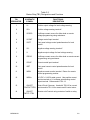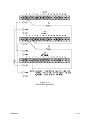
1
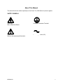
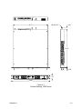
3300 Series
DC Power Supplies
Operation Manual
PowerTen
9250 Brown Deer Road
San Diego, CA 92121-2294
1-800-978-6680
Tel: (858) 458-0253
Fax: (858) 458-0237
Email: [email protected]
www.powerten.com
©2002 by PowerTen. This document contains information proprietary to PowerTen. The information contained
herein is not to be duplicated or transferred in any manner without prior written permission from PowerTen.
January 11, 2002
Document No. M520086-01 Rev A
Safety Notice
Before applying power to the system, verify that the unit is configured properly for the user's
particular application.
The 3300 series of power supplies is intended for rack mounted application only. Use of the
power supplies outside of a rack mount enclosure will expose the user to high voltage and/or
high current sources. Extreme caution must be used under these circumstances.
The analog control inputs (connectors J1 and J2) on the rear panel are referenced to the
negative output of the power supply. Grounding the positive output of the power supply or
biasing the output of the supply above chassis potential will cause these inputs (along with the
output of the supply) to have a potentially hazardous offset voltage. Exercise caution under
these conditions. Under no circumstances should the output of the supply be biased more than
500 volts from chassis potential.
Installation and service must be performed only by properly trained and qualified
personnel who are aware of dealing with attendant hazards. This includes simple tasks
such as fuse verification.
Ensure that the AC power line ground is connected properly to the unit input connector
or chassis. Similarly, other power ground lines including those to application
maintenance equipment must be grounded properly for both personnel and equipment
safety.
Always ensure that facility AC input power is de-energized prior to connecting or disconnecting
the input/output power cables.
Warning:
Lethal voltages may be present inside the power supply even when the AC input
voltage is disconnected. Only properly trained and qualified personnel should
remove covers and access the inside of the power supply.
During normal operation, the operator does not have access to hazardous voltages within the
chassis. However, depending on the user's application configuration, HIGH VOLTAGES
HAZARDOUS TO HUMAN SAFETY may be generated normally on the output terminals.
Ensure that the output power lines are labeled properly as to the safety hazards and that any
inadvertent contact with hazardous voltages is eliminated.
Due to filtering, the unit has high leakage current to the chassis. Therefore, it is essential to
operate this unit with a safety ground.
This unit is designed to be permanently connected to the power source and as such must have
a readily accessible disconnect device incorporated in the fixed wiring.
After the unit has been operating for some time, the metal near the rear of the unit may be hot
enough to cause injury. Let the unit cool before handling.
These operating instructions form an integral part of the equipment and must be available to the
operating personnel at all times. All the safety instructions and advice notes are to be followed.
Neither Power Ten nor any of the subsidiary sales organizations can accept responsibility for
personal, material or consequential injury, loss or damage that results from improper use of the
equipment and accessories.
M520086-01
ii
SERVICE SAFETY NOTICES
WARNING!
HAZARDOUS VOLTAGES IN EXCESS OF 480 V
RMS, 700 V PEAK MAY BE PRESENT WHEN
COVERS ARE REMOVED.
QUALIFIED
PERSONNEL MUST USE EXTREME CAUTION
WHEN SERVICING THIS EQUIPMENT. CIRCUIT
BOARDS, TEST POINTS, AND OUTPUT
VOLTAGES MAY BE FLOATING ABOVE
CHASSIS GROUND.
WARNING!
TO GUARD AGAINST RISK OF ELECTRICAL
SHOCK DURING OPEN COVER CHECKS, DO
NO
TOUCH
ANY
PORTION
OF
THE
ELECTRICAL CIRCUITS.
EVEN WHEN THE
POWER IS OFF, CAPACITORS CAN RETAIN AN
ELECTRICAL
CHARGE.
USE
SAFETY
GLASSES DURING OPEN COVER CHECKS TO
AVOID PERSONAL INJURY BY ANY SUDDEN
FAILURE OF A COMPONENT.
WARNING!
SOME CIRCUITS ARE LIVE EVEN WITH THE
FRONT PANEL SWITCH TURNED OFF.
SERVICE,
FUSE
VERIFICATION,
AND
CONNECTION OF WIRING TO THE CHASSIS
MUST BE ACCOMPLISHED AT LEAST FIVE
MINUTES AFTER POWER HAS BEEN REMOVED
VIA EXTERNAL MEANS; ALL CIRCUITS AND/OR
TERMINALS TO BE TOUCHED MUST BE
SAFETY GROUNDED TO THE CHASSIS.
WARNING!
QUALIFIED SERVICE PERSONNEL NEED TO
BE AWARE THAT SOME HEAT SINKS ARE NOT
AT GROUND, BUT AT HIGH POTENTIAL.
M520086-01
iii
FCC NOTICE
This equipment has been tested and found to
comply with the limits for a Class A digital device,
pursuant to part 15 of the FCC Rules. These limits
are designed to provide reasonable protection
against harmful interference when the equipment is
operated in a commercial environment.
This
equipment generates, uses, and can radiate radio
frequency energy and, if not installed and used in
accordance with the instruction manual, may cause
harmful interference to radio communications.
Operation of this equipment in a residential area is
likely to cause harmful interference in which case
the user will be required to correct the interference
at his own expense.
M520086-01
iv
About This Manual
This manual has been written expressly for the Power Ten 3300 Series of power supplies.
SAFETY SYMBOLS
CAUTION
Risk of Electrical Shock
Protective Conductor Terminal
CAUTION
Refer to Accompanying Documents
Alternating Current (AC)
M520086-01
v
TABLE OF CONTENTS
Chapter 1 DESCRIPTION OF EQUIPMENT____________________________________ 1-1
1.1 PURPOSE AND CAPABILITIES _______________________________________________ 1-1
1.2 TECHNICAL CHARACTERISTICS_____________________________________________ 1-1
Chapter 2 INSTALLATION __________________________________________________ 2-1
2.1 INSPECTION _______________________________________________________________ 2-1
2.2 INPUT/OUTPUT CONNECTORS ______________________________________________ 2-1
2.3 LOCATION AND MOUNTING ________________________________________________ 2-1
2.4 CHECKOUT AND PRELIMINARY ADJUSTMENTS ______ Error! Bookmark not defined.
Chapter 3 OPERATING INSTRUCTIONS ______________________________________ 3-4
3.1 CONTROLS AND INDICATORS_______________________________________________ 3-4
3.1.1
3.1.2
3.1.3
3.1.4
3.1.5
3.1.6
3.1.7
3.1.8
3.1.9
Local Operation ________________________________________________________________ 3-4
Remote Current Programming _____________________________________________________ 3-7
Remote Voltage Programming _____________________________________________________ 3-7
Remote Sensing ________________________________________________________________ 3-8
Remote Output On/Off Control_____________________________________________________ 3-8
Auto-Parallel Operation __________________________________________________________ 3-9
Auto-Series Operation ___________________________________________________________ 3-9
Auto-Tracking Operation _________________________________________________________ 3-9
Output overvoltage Protection ____________________________________________________ 3-10
Chapter 4 MAINTENANCE AND CALIBRATION _______________________________ 4-1
4-1. INTRODUCTION ___________________________________________________________ 4-1
4-2. PREVENTIVE MAINTENANCE _______________________________________________ 4-1
4-3. CALIBRATION AND ADJUSTMENTS _________________________________________ 4-3
4.1.1
4.1.2
Converter Assembly Calibration____________________________________________________ 4-3
Display Assembly _______________________________________________________________ 4-6
M520086-01
vi
LIST OF TABLES
TABLE 1-1 3300 SERIES TECHNICAL CHARACTERISTICS ...................................................... 1-2
TABLE 1-2 3300 SERIES TECHNICAL CHARACTERISTICS ...................................................... 1-4
TABLE 2-1 3300 SERIES INPUT/OUTPUT CONNECTORS ........................................................ 2-2
TABLE 3-1 3300 SERIES CONTROLS AND INDICATORS.......................................................... 3-5
TABLE 3-2 BARRIER STRIP (TB1) DESIGNATIONS AND FUNCTIONS .................................... 3-6
TABLE 4-1 PREVENTIVE MAINTENANCE SCHEDULE .............................................................. 4-1
TABLE 4-2 INSPECTION AND CORRECTIVE ACTION............................................................... 4-2
LIST OF FIGURES
FIGURE 3-1 3300 SERIES CONTROLS AND INDICATORS ....................................................... 3-4
FIGURE 3-2 NORMAL CONNECTION PATTERN...................................................................... 3-11
FIGURE 3-3 REMOTE RESISTANCE PROGRAMMING OF OUTPUT CURRENT ................... 3-11
FIGURE 3-4 REMOTE VOLTAGE PROGRAMMING OF OUTPUT CURRENT ......................... 3-12
FIGURE 3-5 REMOTE RESISTANCE PROGRAMMING OF OUTPUT VOLTAGE.................... 3-12
FIGURE 3-6 REMOTE VOLTAGE PROGRAMMING OF OUTPUT VOLTAGE.......................... 3-13
FIGURE 3-7 REMOTE SENSING OPERATION.......................................................................... 3-13
FIGURE 3-8 REMOTE ON/OFF CONTROL BY CONTACT CLOSURE ..................................... 3-14
FIGURE 3-9 REMOTE ON/OFF OPERATION USING AC/DC VOLTAGE SOURCE ................. 3-14
FIGURE 3-10 AUTO-PARALLEL OPERATION........................................................................... 3-15
FIGURE 3-11 AUTO-SERIES OPERATION................................................................................ 3-16
FIGURE 3-12 AUTO-TRACKING OPERATION .......................................................................... 3-17
M520086-01
vii
Chapter 1
DESCRIPTION OF EQUIPMENT
1.1
PURPOSE AND CAPABILITIES
The Power Ten 3300 Series power supplies are general purpose power supplies designed
specifically for laboratory test and systems applications requiring variable DC sources with good
regulation and low output ripple characteristics. Models of the 3300 Series are constant
current/constant voltage supplies with an automatic crossover feature. They provide up to 1000
watts of DC power over a wide range of voltage and current levels.
1.2
TECHNICAL CHARACTERISTICS
The physical, electrical and environmental characteristics for the 3300 Series are listed in
Tables 1-1 and 1-2.
M520086-01
1-1
Table 1-1
3300 Series Technical Characteristics
PARAMETERS
SPECIFICATIONS
PHYSICAL CHARACTERISTICS:
Width
Depth
Height
Weight
19.00 in.
18.50 in
1.75 in.
15 lb. max.
ELECTRICAL CHARACTERISTICS:
Input Power (Standard)
Voltage
Frequency
Phases
95 to 127 VAC, 190 to 253 VAC (Option)
47 to 63 Hz
Single, 2-wire plus gnd
Regulation (Line or Load)
Voltage
Current
0.1% of max. output voltage
0.1% of max. output current
Noise and Ripple (RMS)
30 mV max.
Transient Response
A 30% step load will recover to within 2%
of original value within 10 ms.
Stability
+0.05% of set point per 8 hr. after warm-up
and at a fixed line, load and temperature.
Remote Control/Monitor
On/Off control via contact closure,
6-120 VDC or 12-240 VAC.
Power Density
2.5 Watts/cubic in.
Power Factor
.99 min. at full load
Total Harmonic
2.5% max.
M520086-01
1-2
Table 1-1
3300 Series Technical Characteristics - Continued
PARAMETERS
SPECIFICATIONS
Remote Programming
Resistive:
Constant Voltage (0-100%)
Constant Current (0-100%)
0 - 5k ohms
0 - 5k ohms
Voltage:
Constant Voltage (0-100%)
Constant Current (0-100%)
0 - 5 VDC
0 - 100 mV
Current:
Constant Voltage (0-100%)
Constant Current (0-100%)
0 - 1 mA
0 - 1 mA
Remote Sensing
Terminals are provided to sense output
voltage at point of load. Maximum line drop
3% of rated voltage per line.
ENVIRONMENTAL
CHARACTERISTICS:
Temperature Coefficient
0.02%/°C of max. output voltage rating for
voltage set point.
0.03%/°C of max. output current rating for
current set point.
Ambient Temperature
Operating
Storage
0 to 50°C
-40° to 75°C
Cooling
Internal blowers
M520086-01
1-3
Table 1-2
3300 Series Technical Characteristics
MODEL NUMBER
OUTPUT DC
VOLTS
OUTPUT DC
AMPS
OUTPUT
RIPPLE (RMS)
7.575
0-7.5
75
30 mV
7.5125
0-7.5
125
30 mV
1060
0-10
60
30 mV
10100
0-10
100
30 mV
2030
0-20
30
30 mV
2050
0-30
50
30 mV
3020
0-30
20
30 mV
3033
0-30
33
30 mV
4015
0-40
15
30 mV
4025
0-40
25
30 mV
5020
0-50
20
30 mV
6010
0-60
10
30 mV
6016
0-60
16
30 mV
8006
0-80
6
50 mV
8012
0-80
12
50 mV
10010
0-100
10
50 mV
1208
0-120
8
50 mV
1507
0-150
7
50 mV
M520086-01
1-4
Chapter 2
INSTALLATION
2.1
INSPECTION
Inspect the shipping carton for possible damage before unpacking the unit. Carefully unpack
the equipment. Save all packing materials until inspection is complete. Verify that all items
listed on the packing slips have been received. Visually inspect all exterior surfaces for broken
knobs, connectors or meters. Inspect for dented or damaged exterior surfaces. External
damage may be an indication of internal damage. If any damage is evident, immediately
contact the carrier that delivered the unit and submit a damage report. Failure to do so could
invalidate future claims.
2.2
INPUT/OUTPUT CONNECTORS
Table 2-1 lists all external connections for the 3300 Series models.
For permanently connected equipment, a readily accessible disconnect device shall be incorporated in
the fixed wiring. For pluggable equipment, the socket outlet shall be installed near the equipment and
shall be easily accessible.
2.3
LOCATION AND MOUNTING
The 3300 Series models are intended for mounting in a standard 19.0-inch equipment rack.
Four captive screws, two on each side of the front panel, are used to secure the unit in place.
Optional slide mounting is available.
NOTICE
The unit should be provided with
proper ventilation. The top, rear and
both sides of the unit should be free
of obstructions.
Follow the instructions in paragraph 3.1.1 for setup and operation of the equipment.
M520086-01
2-1
Table 2-1
Output Connection Descriptions
SUPPLY TYPE
CONNECTION DESCRIPTION
Output <=60V
Bus Bar with hole for 1/4” bolt
Output >=80V
Terminal Block with 6-32 screws
Table 2-2
Input Connection Descriptions
SUPPLY TYPE
CONNECTION DESCRIPTION
3300, 3300I
Terminal Block with 6-32 screws
Table 2-3
3300 Series Input/Output Connectors
CONNECTOR
FUNCTION
CONNECTS TO
TB2 - AC
TB2 - AC
CHASSIS - GND
Prime Power Input (Std)*
Prime Power Input (Std)*
95 to 127 VAC
47 to 63 Hz
Power Source
Pos. Bus Bar
Neg. Bus Bar
GND Stud
Output Power
Output Power
User load(s)
User Load(s)
TB1
Control Interface
See Table 3-2 for a
description
*190 to 253 VAC is available as a factory option
M520086-01
2-2
2.4
WIRE SIZING
Care must be taken to properly size all conductors for the input and output of the power supply.
Table 2-5 below gives minimum recommended wire size for the input. This table is derived
from the National Electrical Code and is for reference only. Local laws and conditions may
have different requirements. The table is for copper wire only.
Table 2-4
Minimum Wire SizeTable
SIZE
AWG
MCM
14
12
10
8
6
4
3
2
1
0
2.5
TEMPERATURE RATING OF COPPER CONDUCTOR
60 °C
75 °C
85 °C
90 °C
TYPES
TYPES
TYPES
TYPES
RUW, T, TW, FEPW, RH,
V, MI
TA, TBS, SA,
UF
RHW, RUH,
AVB, SIS, FEP,
THW, THWN,
FEPB, RHH,
XHHW, USE,
THHN, XHHW
ZW
CURRENT RATING
20
20
25
25
25
25
30
30
30
35
40
40
40
50
55
55
55
65
70
75
70
85
95
95
85
100
110
110
95
115
125
130
110
130
145
150
125
150
165
170
OUTLINE DRAWINGS
The following page (figure 2-1) shows the outlines and overall dimensions for 3300 product line.
M520086-01
2-2
NEG
TB1
POS
TB2
16.75
Ø0.25 2 PL
1.00
18.15
0.125
1.75
19.00
Figure 2-1
Outline Drawing, 3300 Series
M520086-01
2-3
Chapter 3
OPERATING INSTRUCTIONS
3.1
CONTROLS AND INDICATORS
Front panel controls and indicators for the 3300 Series are identified in Figure 3-1 with index
numbers keyed to Table 3-1. Table 3-1 provides a description of all operator controls and
indicators.
3.1.1
Local Operation
Units are shipped from the factory configured for local voltage/current control and local voltage
sensing. This configuration is used for applications where the IR drop of the load wires is
insufficient to degrade performance at the load. Prior to turning the unit on, rotate the voltage
and current potentiometers fully counterclockwise (minimum output). Then switch the power to
the ON position and adjust the voltage and current to the desired output.
Figure 3-1
3300 Series Controls and Indicators
M520086-01
3-4
Table 3-1
3300 Series Controls and Indicators
FIGURE &
INDEX NO.
CONTROL/INDICATOR
FUNCTION
3-1
1
Circuit Breaker
Provides fault protection
2
Power Switch
Applies AC power to the power
supply.
3
VOLTAGE Meter
Measures voltage output.
4
Voltage Mode Indicator
Indicates the power supply is operating
in the voltage mode.
5
Current Mode Indicator
Indicates the power supply is operating
in the current mode
6
CURRENT Meter
Measures current output.
7
Overvoltage (OV) Indicator
Indicates output voltage has exceeded
preset level, and power supply output
is turned off.
8
Fault Indicator
Adjusts overvoltage trip level.
9
Local Output Current Control
Adjusts current output to a desired
level.
10
Local Output Voltage Control
Adjusts voltage output to a desired
level.
M520086-01
3-5
Table 3-2
Barrier Strip (TB1) Designations and Functions
TB1
DESIGNATOR
SCHEMATIC
SYMBOL
FUNCTIONAL
DESCRIPTION
1
V+
Positive output voltage for local voltage sensing.
2
VS+
Positive voltage sensing terminal.*
3
VPROG
1 milliamp current source for either local or remote
voltage programming using resistance.
4
VCONT
Voltage control input terminal.
5
VSET
6
VS-
Front panel voltage control potentiometers for local
control.
.
Negative voltage sensing terminal.*
7
V-
Negative output voltage for local voltage sensing.
8
IPROG
1 milliamp current source for either local or remote current
programming using resistance.
9
ICONT
Current control input terminal.
10
ISET
Front panel current control potentiometers for local
control.
11
IMON
Negative current monitor terminal. Return for remote
current programming resistor.
12
IMON+
0-5 VDC = 0-100% rated current. Use positive current
monitor terminal or 0-1 milliamp auto-tracking control
output terminal. Referenced to TB1-13.
13
ON/OFF
CONTACT RTN
Control Circuit Common. Used with TB1-12 for current
monitor and/or TB1-14 for remote on/off control return.
14
ON/OFF
CNTCT CTRL
Remote on/off control using contacts of switch or relay.
*Except in models in excess of 60 VDC output.
M520086-01
3-6
Table 3-2
Barrier Strip (TB1) Designations and functions - Continued
TB1
DESIGNATOR
SCHEMATIC
SYMBOL
FUNCTIONAL
DESCRIPTION
15
ON/OFF
AC/DC RTN
Return for AC/DC voltage source used for remote on/off
control.
16
ON/OFF
AC/DC
Externally supplied AC/DC voltage source for on/off
output voltage control. This is a positive (+) terminal for
DC voltage.
3.1.2
Remote Current Programming
The remote current programming is used for applications that require the output current be
programmed (controlled) from a remote source. An external resistance or external voltage
source may be used as a programming device. When using remote current programming,
a shielded, twisted-pair, hookup wire is recommended to prevent noise interference with
programming signals.
a.
External Current Programming Using Resistance. The resistance coefficient
for remote current programming is 100 ohms = 100% rated output. The
programming current from the current control programming terminal A3 is
factory set for 1 milliamp. If multiple switches or relays are used to program
different levels, make-before-break contacts are recommended. See Figure 33 for connection requirements.
b.
External Current Programming Using a Voltage Source. The voltage
coefficient for remote current programming is 1 millivolt per percent of rated
output current or 100 millivolts = 100% of rated output. On models with 10 V
programming, the programming coefficient is 0.1 volt per percent of rated
output or 10 volts = 100%. See Figure 3-4 for connection requirements.
3.1.3
Remote Voltage Programming
The remote voltage programming configuration is used for applications that require the
output voltage be programmed (controlled) from a remote source. An external resistance or
external floating voltage source may be used as a programming device. When using
remote voltage programming, a shielded, twisted-pair, hookup wire is recommended to
prevent noise interference with programming signals.
a.
External Voltage Programming Using Resistance. The resistance coefficient
for remote voltage programming is 5k ohms = 100% of rated output voltage.
The programming current from terminal 3 is factory set to 1 mA. If multiple
switches or relays are used to program different levels, make-before-break
contacts are recommended. See Figure 3-5 for connection requirements.
b.
External Voltage Programming The voltage coefficient for external voltage
programming is 5 volts = 100% of rated output voltage. On models with 10 V
M520086-01
3-7
programming, the programming coefficient is 0.1 volt per percent of rated
output or 10 volts = 100%. See Figure 3-6 for connection requirements.
3.1.4
Remote Sensing
In applications where the load is located some distance from the power supply, or the
voltage drop of the power output leads significantly interferes with load regulation, remote
voltage sensing may be used. When remote sensing is used, voltage is regulated at the
load versus the power supply output terminals. To connect the power supply for remote
voltage sensing (see Figure 3-7 for connection requirements), perform the following
procedure.
CAUTION
If the power supply is operated with load power
lines disconnected and sensing line connected,
internal power supply damage may occur. (Output
current then flows through sensing terminals.)
a.
Remove jumper between the positive sense terminal (TB1-2) and the positive
output monitor terminal (TB1-1).
b.
Remove jumper between the negative sense terminal (TB1-6) and the negative
output monitor terminal (TB1-7).
c.
Connect sensing leads from the load positive to TB1-2 and the load negative to
TB1-6. A shielded, twisted pair is recommended to avoid potential noise
interference.
3.1.5
Remote Output On/Off Control
Remote on/off control may be accomplished by contact closure or by an isolated external
AC/DC voltage source.
a.
Remote on/off by contact closure. Output is on when contacts are closed.
See Figure 3-8 for connection requirements.
b.
Remote on/off control may be accomplished by an external 12 to 240 VAC or 6
to 120 VDC source. Application of AC/DC voltage will turn on the power
supply. See Figure 3-9 for connection requirements.
M520086-01
3-8
NOTE
The following modes of operation are used for
applications requiring more current or voltage than
is available from a single power supply. To meet
the requirements for greater output voltage or
current, two or more supplies may be connected in
series or parallel.
3.1.6
Auto-Parallel Operation
In the auto-parallel mode of operation, a master/slave configuration is established.
CAUTION
When using two or more supplies in parallel,
damage may occur to slave(s) crowbar circuits if
slave overvoltage level is set lower than the level
set on the master. To prevent damage, set all
slave units overvoltage-set potentiometers fully
clockwise; and set the master unit to the desired
trip level. If overvoltage protection is not desired,
set to trip at maximum rated voltage (less than fully
clockwise).
To set up the auto-parallel mode of operation, connect all outputs in parallel to the load.
Connect jumper from master TB1-12 to slave TB1-9 and TB1-10. Remove jumper between
slave TB1-8 and TB1-9. Rotate slave voltage control potentiometers to maximum, and
adjust current control potentiometers for balanced output currents during operation. Once
adjusted, output currents will track automatically. If tracking is not close, perform the
calibration procedures listed in Chapter 4. See Figure 3-10 for connection requirements.
3.1.7
Auto-Series Operation
In the auto-series mode of operation, a master/slave configuration is established. With two
more supplies connected in series, one is established as master and the remaining supply
as the slave. The master supply must always be the most positive unit. When operating in
the auto-series mode, voltage control potentiometer settings determine the percentage of
total load voltage contribution by the slave unit. Current control potentiometer of the slave
unit is active and should be set to maximum clockwise position. See Figure 3-11 for
connection requirements.
3.1.8
Auto-Tracking Operation
In the auto-tracking mode of operation, a master/slave configuration is established. In this
configuration, two or more supplies may be connected with common negative outputs. The
slave(s) output voltage is a percentage of the master as controlled by the value of Rx.
M520086-01
3-9
Individual current controls on both master and slave(s) remain active. See Figure 3-12 for
connection requirements.
3.1.9
Output overvoltage Protection
If the power supply is equipped with an overvoltage crowbar, the front panel will contain
overvoltage adjustment. The potentiometer controlling overvoltage may be adjusted
through an access hole in the front panel.
NOTE
All overvoltage circuitry has been properly adjusted
to their respective unit before leaving the factory.
For trip levels less than the maximum output voltage or to check the overvoltage circuitry,
perform the following procedure.
a.
Set the potentiometer fully clockwise.
b.
Adjust the power supply output voltage to the desired trip level.
c.
Slowly adjust the potentiometer counterclockwise until overvoltage is tripped.
M520086-01
3-10
Figure 3-2
Normal Connection pattern
Figure 3-3
Remote Resistance Programming of Output Current
M520086-01
3-11
Figure 3-4
Remote Voltage Programming of Output Current
Figure 3-5
Remote Resistance Programming of Output Voltage
M520086-01
3-12
Figure 3-6
Remote Voltage Programming of Output Voltage
Figure 3-7
Remote Sensing Operation
M520086-01
3-13
Figure 3-8
Remote On/Off Control by Contact Closure
Figure 3-9
Remote On/Off Operation Using AC/DC Voltage Source
M520086-01
3-14
Figure 3-10
Auto-Parallel Operation
M520086-01
3-15
Figure 3-11
Auto-Series Operation
M520086-01
3-16
Figure 3-12
Auto-Tracking Operation
M520086-01
3-17
Chapter 4
MAINTENANCE AND CALIBRATION
4.1
INTRODUCTION
This chapter contains preventive maintenance information and calibration procedures for the
3300 Series.
WARNING
All maintenance that requires removal of the cover
of the unit should only be done by properly trained
and qualified personnel. Hazardous voltages exist
inside the unit.
4.2
PREVENTIVE MAINTENANCE
Preventive maintenance for the 3300 Series consists of scheduled inspection and cleaning.
a.
Schedule. Table 4-1 lists the preventive maintenance routines and the
recommended performance intervals.
b.
Inspection. Table 4-2 lists the visual inspection checks to be performed. It also
indicates the corrective action to be taken.
c.
Cleaning. Cleaning requirements are based on the need established during
inspection. If cleaning is required, follow the instruction listed in the corrective
action column of Table 4-2.
Table 4-1
Preventive Maintenance Schedule
PREVENTIVE MAINTENANCE
ROUTINE
RECOMMENDED PERFORMANCE
INTERVAL
Inspection
Annual
Cleaning
As Required
M520086-01
4-1
Table 4-2
Inspection and Corrective Action
ITEM
External Connector
plugs and jacks
INSPECT FOR
Looseness, bent or corroded
contacts, damage or improper
seating in mating connector
CORRECTIVE ACTION
Clean contacts with solvent
moistened cloth, soft bristle brush,
small vacuum or low compressed
air.
Replace connectors damaged,
deeply corroded, or improperly
seated in mating connector.
Chassis, blower &
extruded heatsinks
Dirt and Corrosion
Clean with cloth moistened with
soapy water.
External Electrical
Wiring
Broken, burned or pinched
wire; frayed, worn or missing
insulation
Repair or replace defective wires.
External Solder
Connections
Corrosion, loose, cracked, or
dirty connections
Clean and resolder connections.
Dirt and moisture
buildup
Short circuits, arcing, corrosion,
overheating
Clean as required.
Front panel controls
and meters
Dirt and corrosion
Clean with cloth moistened with
soapy water.
Use a Kimwipe tissue and glass
cleaning compound to clean the
meter faces.
M520086-01
4-2
4.3
CALIBRATION AND ADJUSTMENTS
To perform the following calibration and adjustment procedures, the cover must be removed
from the power supply. Because removal of the cover allows access to potentially hazardous
power voltages (up to 253 VAC or 358 VDC) and because of the importance of accurate
readings to performance, only technically trained personnel should perform calibration
procedures.
WARNING
Hazardous voltages (up to 253 VAC or 358 VDC)
during equipment operations. Press power switch
to OFF position and disconnect power cable from
power source. Allow a minimum of 5 minutes for
discharge of storage capacitance before removing
the cover or performing any maintenance function.
Wear safety glass with cover removed.
The calibration Test Setup procedures require the following: remove prime power; connect the
power supply to a resistive load capable of full-rated voltage and current. Connect a precision
current shunt in series with either the positive or negative output between the power supply and
the resistive load. Two digital multimeters are required to perform the calibration procedures.
4.3.1
Converter Assembly Calibration
Voltage Reference
The voltage reference is provided by an adjustable current regulator Q15. To calibrate
for the 1 mA programming coefficient (constant voltage), the following sequence is
recommended.
a.
Remove all jumpers and external connections to TB1-3.
b.
Set current control potentiometer on front panel fully counterclockwise.
c.
Connect a precision digital multimeter (DMM) to TB1-3(+) with reference to
TB1-7(-). Set DMM to DC milliamps and 2 milliamp range.
d.
Apply power to the power supply.
e.
Adjust R69 for 1.000 milliamps on DMM.
Current Reference
The current reference is a precision current source consisting of Q16 and associated
resistors. Calibration is accomplished by adjusting R71. The following sequence is
recommended.
a.
M520086-01
Remove all jumpers and external connections to TB1-8.
4-3
b.
Set voltage control potentiometer on front panel fully counterclockwise.
c.
Connect a precision DMM to TB1-8(+) with reference to TB1-11(-). Set DMM to
DC milliamps and 2 milliamp range.
d.
Apply power to power supply.
e.
Adjust R71 for 1.000 milliamps on DMM.
Current Zero Calibration
The voltage control circuit (U8) zero is adjusted by R106. The following sequence is
recommended.
a.
Connect jumper (short circuit) between TB1-4 and TB1-6.
b.
Connect resistive load and DMM across output terminals of power supply. Set
DMM to read DC volts and approximately 200 millivolt range.
c.
Set current control potentiometer full clockwise.
d.
Apply power to power supply.
e.
Adjust R106 until the power supply output voltage starts to increase in the
normal polarity. Reverse adjustment direction of R106 until output voltage
decreases to zero reading on the DMM. Do not continue adjustment once the
output reads zero millivolts.
Voltage Full-Scale Calibration
Full-scale voltage calibration is accomplished by adjusting R101. The following
sequence is recommended.
a.
Connect a resistive load across output terminals.
b.
Connect a DMM between TB1-2 and TB1-6. Set DMM to DC volts and the
scale to read maximum rated power supply voltage.
c.
Connect a second DMM between TB1-4(+) and TB1-6(-). Set DMM to DC volts
and scale to read 5.00 volts.
d.
Rotate current control to maximum clockwise.
e.
Apply power to power supply.
f.
Rotate voltage control for 5.00 volt reading to DMM attached to TB1-4 and
TB1-6.
g.
Adjust R101 until output voltage reading is 100% of rated output voltage DC
between TB1-2 and TB1-6.
Current Zero Calibration
The current control circuit (U7) zero is adjusted by R87. The following sequence is
recommended.
a.
Connect a jumper (short circuit) between TB1-9 and TB1-11.
b.
Connect a resistive load and DMM across the output terminals of the power
supply. Set DMM to read DC volts and approximately 200 millivolt range.
c.
Set voltage control potentiometer on front panel fully clockwise.
d.
Apply power to power supply.
M520086-01
4-4
e.
Adjust R87 until the power supply output voltage starts to increase in normal
polarity. Reverse adjustment direction of R87 until output voltage decreases to
zero reading on the DMM. Do not continue adjustment when the output reads
zero volts.
Current Full-Scale Calibration
Full-scale current calibration is accomplished by adjusting R88. The following sequence
is recommended.
a.
Connect an external calibrated current shunt between the power supply
negative output and a resistive load bank capable of full-rated power.
(Optionally, the shunt may be connected between the power supply positive
and negative output bus bars.)
b.
Connect DMM across current shunt sensing terminals.
c.
Connect a DMM between TB1-9(+) and TB1-11(-). Set to 200 millivolt range.
d.
Set front panel voltage control potentiometer fully clockwise.
e.
Apply power to power supply.
f.
Adjust front panel current control for 100 millivolt reading on DMM across TB19 and TB1-11.
g.
Adjust R88 until rated output current flows through external current shunt.
Current Monitor/Parallel Tracking Amplifier Zero Calibration
The Current monitor/parallel tracking amplifier zero is accomplished by adjusting R79.
The following sequence is recommended.
a.
Connect a jumper (short circuit) between TB1-9 and TB1-11.
b.
Connect a resistive load across output terminals.
c.
Connect a DMM between TB1-12(+) and TB1-13(-). Set DMM to DC volts on
0.2 volt scale.
d.
Set front panel voltage and current control potentiometers fully
counterclockwise.
e.
Apply power to power supply
f.
Adjust R79 to 0.00 volts on DMM.
g.
Remove power from power supply.
h.
Remove jumper between TB1-9 and TB1-11.
i.
Remove resistive load from power supply output terminals.
j.
Reconfigure power supply for normal operation.
M520086-01
4-5
Current Monitor/Parallel Tracking Amplifier Full-Scale Calibration
The current monitor/parallel tracking amplifier is accomplished by adjusting R77. The
following sequence is recommended.
a. Connect an external calibrated current shunt between the power supply negative
output and a resistive load bank capable of full-rated power. (As an option, the
shunt may be connected between the power supply positive and negative output
bus bars.)
b. Connect a DMM across the current shunt sensing.
c. Connect a DMM between TB1-12 and TB1-13.
d. Set front panel voltage control potentiometers fully clockwise.
e. Apply power to power supply.
f.
Set front panel current control potentiometers for rated output current through
external current shunt.
g. Adjust R77 for 5.00 volts DC reading on DMM connected between TB1-12 and
TB1-13.
h. Remove power from power supply.
i.
4.3.2
Reconfigure power supply for normal operation.
Display Assembly
Meter Zero Calibration
The zero set for both voltage and current front panel meter is automatic.
Meter Full-Scale Calibration
The full-scale adjustment for the digital panel meters M1 and M2 is adjusted by R8 and
R11, respectively, of the display assembly 10-010-086-00. R8 is for full-scale current
meter calibration, and R11 is for full-scale voltage meter calibration. Both resistors are
accessible from inside the power supply when the cover is removed.
To calibrate for full-scale voltage or current, adjust the power supply to maximum rated
output voltage (or current) using external calibrated meters and adjust the appropriate
meter to correspond to the rated output voltage or current.
M520086-01
4-6