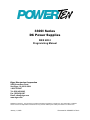
1
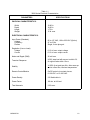
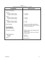
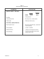
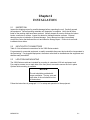
3300I Series
DC Power Supplies
IEEE 488.2
Programming Manual
Elgar Electronics Corporation
9250 Brown Deer Road
San Diego, CA 92121-2294
1-800-733-5427
Tel: (858) 450-0085
Fax: (858) 458-0267
Email: [email protected]
www.elgar.com
©2002 by PowerTen. This document contains information proprietary to PowerTen. The information contained
herein is not to be duplicated or transferred in any manner without prior written permission from PowerTen.
January 11, 2002
Document No. M520087-01 Rev A
Safety Notice
Before applying power to the system, verify that the unit is configured properly for the user's
particular application.
The 3300I series of power supplies is intended for rack mounted application only. Use of the
power supplies outside of a rack mount enclosure will expose the user to high voltage and/or
high current sources. Extreme caution must be used under these circumstances.
The analog control inputs (connectors J1 and J2) on the rear panel are referenced to the
negative output of the power supply. Grounding the positive output of the power supply or
biasing the output of the supply above chassis potential will cause these inputs (along with the
output of the supply) to have a potentially hazardous offset voltage. Exercise caution under
these conditions. Under no circumstances should the output of the supply be biased more than
500 volts from chassis potential.
Installation and service must be performed only by properly trained and qualified
personnel who are aware of dealing with attendant hazards. This includes simple tasks
such as fuse verification.
Ensure that the AC power line ground is connected properly to the unit input connector
or chassis. Similarly, other power ground lines including those to application
maintenance equipment must be grounded properly for both personnel and equipment
safety.
Always ensure that facility AC input power is de-energized prior to connecting or disconnecting
the input/output power cables.
Warning:
Lethal voltages may be present inside the power supply even when the AC input
voltage is disconnected. Only properly trained and qualified personnel should
remove covers and access the inside of the power supply.
During normal operation, the operator does not have access to hazardous voltages within the
chassis. However, depending on the user's application configuration, HIGH VOLTAGES
HAZARDOUS TO HUMAN SAFETY may be generated normally on the output terminals.
Ensure that the output power lines are labeled properly as to the safety hazards and that any
inadvertent contact with hazardous voltages is eliminated.
Due to filtering, the unit has high leakage current to the chassis. Therefore, it is essential to
operate this unit with a safety ground.
This unit is designed to be permanently connected to the power source and as such must have
a readily accessible disconnect device incorporated in the fixed wiring.
After the unit has been operating for some time, the metal near the rear of the unit may be hot
enough to cause injury. Let the unit cool before handling.
These operating instructions form an integral part of the equipment and must be available to the
operating personnel at all times. All the safety instructions and advice notes are to be followed.
Neither Power Ten nor any of the subsidiary sales organizations can accept responsibility for
personal, material or consequential injury, loss or damage that results from improper use of the
equipment and accessories.
M520087-01
ii
SERVICE SAFETY NOTICES
WARNING!
HAZARDOUS VOLTAGES IN EXCESS OF 480 V
RMS, 700 V PEAK MAY BE PRESENT WHEN
COVERS ARE REMOVED.
QUALIFIED
PERSONNEL MUST USE EXTREME CAUTION
WHEN SERVICING THIS EQUIPMENT. CIRCUIT
BOARDS, TEST POINTS, AND OUTPUT
VOLTAGES MAY BE FLOATING ABOVE
CHASSIS GROUND.
WARNING!
TO GUARD AGAINST RISK OF ELECTRICAL
SHOCK DURING OPEN COVER CHECKS, DO
NO
TOUCH
ANY
PORTION
OF
THE
ELECTRICAL CIRCUITS.
EVEN WHEN THE
POWER IS OFF, CAPACITORS CAN RETAIN AN
ELECTRICAL
CHARGE.
USE
SAFETY
GLASSES DURING OPEN COVER CHECKS TO
AVOID PERSONAL INJURY BY ANY SUDDEN
FAILURE OF A COMPONENT.
WARNING!
SOME CIRCUITS ARE LIVE EVEN WITH THE
FRONT PANEL SWITCH TURNED OFF.
SERVICE,
FUSE
VERIFICATION,
AND
CONNECTION OF WIRING TO THE CHASSIS
MUST BE ACCOMPLISHED AT LEAST FIVE
MINUTES AFTER POWER HAS BEEN REMOVED
VIA EXTERNAL MEANS; ALL CIRCUITS AND/OR
TERMINALS TO BE TOUCHED MUST BE
SAFETY GROUNDED TO THE CHASSIS.
WARNING!
QUALIFIED SERVICE PERSONNEL NEED TO
BE AWARE THAT SOME HEAT SINKS ARE NOT
AT GROUND, BUT AT HIGH POTENTIAL.
M520087-01
iii
FCC NOTICE
This equipment has been tested and found to
comply with the limits for a Class A digital device,
pursuant to part 15 of the FCC Rules. These limits
are designed to provide reasonable protection
against harmful interference when the equipment is
operated in a commercial environment.
This
equipment generates, uses, and can radiate radio
frequency energy and, if not installed and used in
accordance with the instruction manual, may cause
harmful interference to radio communications.
Operation of this equipment in a residential area is
likely to cause harmful interference in which case
the user will be required to correct the interference
at his own expense.
M520087-01
iv
About This Manual
This manual has been written expressly for the Power Ten 3300I Series of power supplies.
SAFETY SYMBOLS
CAUTION
Risk of Electrical Shock
Protective Conductor Terminal
CAUTION
Refer to Accompanying Documents
Alternating Current (AC)
M520087-01
v
TABLE OF CONTENTS
Chapter 1 DESCRIPTION OF EQUIPMENT___________________________________ 1-1
1.1 PURPOSE AND CAPABILITIES _______________________________________________ 1-1
1.2 TECHNICAL CHARACTERISTICS_____________________________________________ 1-1
Chapter 2 INSTALLATION _________________________________________________ 2-1
2.1 INSPECTION _______________________________________________________________ 2-1
2.2 INPUT/OUTPUT CONNECTORS ______________________________________________ 2-1
2.3 LOCATION AND MOUNTING ________________________________________________ 2-1
2.4 WIRE SIZING ______________________________________________________________ 2-1
2.5 OUTLING DRAWINGS ______________________________________________________ 2-1
Chapter 3 OPERATING INSTRUCTIONS _____________________________________ 3-3
3.1 CONTROLS AND INDICATORS_______________________________________________ 3-3
3.2 SETUP AND OPERATING INSTRUCTIONS _____________________________________ 3-3
3.3 OUTPUT OVERVOLTAGE PROTECTION ______________________________________ 3-5
3.4 IEEE 488.2 _________________________________________________________________ 3-5
3.5 IEEE 488.2 FUNCTION_______________________________________________________ 3-8
Chapter 4 MAINTENANCE AND CALIBRATION ______________________________ 4-1
4.1 INTRODUCTION ___________________________________________________________ 4-1
4.2 PREVENTIVE MAINTENANCE _______________________________________________ 4-1
4.3 CALIBRATION AND ADJUSTMENTS__________________________________________4-3
M520087-01
vi
LIST OF FIGURES
FIGURE 2-1 OUTLINE DRAWING, 3300I SERIES................................................................. 2-2
FIGURE 3-1 SERIES 3300I CONTROL AND INDICATORS................................................... 3-3
FIGURE 3-2 ADDRESS SWITCH........................................................................................... 3-8
FIGURE 3-3 BLOCK DIAGRAM OF HARDWARE CONFIGURATION ..................................3-10
LIST OF TABLES
TABLE 1-1 3300I SERIES ELECTRICAL CHARACTERISTICS ............................................. 1-2
TABLE 1-2 3300I SERIES OUTPUT CHARACTERISTICS .................................................... 1-4
TABLE 1-3 3300I SERIES IEEE CHARACTERISTICS ........................................................... 1-1
TABLE 2-1 OUTPUT CONNECTION DESCRIPTIONS .......................................................... 2-2
TABLE 2-2 INPUT CONNECTION DESCRIPTIONS .............................................................. 2-2
TABLE 2-3 3300I SERIES INPUT/OUTPUT CONNECTORS ................................................. 2-2
TABLE 2-4 MINIMUM WIRE SIZETABLE ............................................................................... 2-1
TABLE 3-1 SERIES 3300I CONTROLS AND INDICATORS .................................................. 3-4
TABLE 4-1 PREVENTIVE MAINTENANCE SCHEDULE ........................................................ 4-1
TABLE 4-2 INSPECTION AND CORRECTIVE ACTION......................................................... 4-2
M520087-01
vii
Chapter 1
DESCRIPTION OF EQUIPMENT
1.1
PURPOSE AND CAPABILITIES
The Power Ten 3300I Series power supply is general purpose power supply designed
specifically for laboratory test and systems applications requiring variable DC sources with good
regulation and low output ripple characteristics. The Series 3300I power supply is constant
current/constant voltage power supplies with an automatic crossover feature. It provides up to
1000 watts of DC power over a wide range of voltage and current levels.
1.2
TECHNICAL CHARACTERISTICS
The characteristics for the IEEE aspects of the 3300I Series are listed in Tables 1-1 through
1-3.
M520087-01
1-1
Table 1-1
3300 Series Electrical Characteristics
PARAMETERS
SPECIFICATIONS
PHYSICAL CHARACTERISTICS:
Width
Depth
Height
Weight
19.00 in.
18.50 in
1.75 in.
15 lb. max.
ELECTRICAL CHARACTERISTICS:
Input Power (Standard)
Voltage
Frequency
Phases
95 to 127 VAC, 190 to 253 VAC (Option)
47 to 63 Hz
Single, 2-wire plus gnd
Regulation (Line or Load)
Voltage
Current
0.1% of max. output voltage
0.1% of max. output current
Noise and Ripple (RMS)
30 mV max.
Transient Response
A 30% step load will recover to within 2%
of original value within 10 ms.
Stability
+0.05% of set point per 8 hr. after warm-up
and at a fixed line, load and temperature.
Remote Control/Monitor
On/Off control via contact closure,
6-120 VDC or 12-240 VAC.
Power Density
2.5 Watts/cubic in.
Power Factor
.99 min. at full load
Total Harmonic
2.5% max.
M520087-01
1-2
Table 1-1
3300I Series Electrical Characteristics - Continued
PARAMETERS
SPECIFICATIONS
Remote Programming
Resistive:
Constant Voltage (0-100%)
Constant Current (0-100%)
0 - 5k ohms
0 - 5k ohms
Voltage:
Constant Voltage (0-100%)
Constant Current (0-100%)
0 - 5 VDC
0 - 100 mV
Current:
Constant Voltage (0-100%)
Constant Current (0-100%)
0 - 1 mA
0 - 1 mA
Remote Sensing
Terminals are provided to sense output
voltage at point of load. Maximum line drop
3% of rated voltage per line.
ENVIRONMENTAL
CHARACTERISTICS:
Temperature Coefficient
0.02%/°C of max. output voltage rating for
voltage set point.
0.03%/°C of max. output current rating for
current set point.
Ambient Temperature
Operating
Storage
0 to 50°C
-40° to 75°C
Cooling
Internal blowers
M520087-01
1-3
Table 1-2
3300I Series Output Characteristics
MODEL NUMBER
OUTPUT DC
VOLTS
OUTPUT DC
AMPS
OUTPUT
RIPPLE (RMS)
7.575
0-7.5
75
30 mV
7.5125
0-7.5
125
30 mV
1060
0-10
60
30 mV
10100
0-10
100
30 mV
2030
0-20
30
30 mV
2050
0-30
50
30 mV
3020
0-30
20
30 mV
3033
0-30
33
30 mV
4015
0-40
15
30 mV
4025
0-40
25
30 mV
5020
0-50
20
30 mV
6010
0-60
10
30 mV
6016
0-60
16
30 mV
8006
0-80
6
50 mV
8012
0-80
12
50 mV
10010
0-100
10
50 mV
1208
0-120
8
50 mV
1507
0-150
7
50 mV
M520087-01
1-4
Table 1-3
3300I Series IEEE Characteristics
PARAMETERS
SPECIFICATIONS
REMOTE CONTROL - IEEE 4888.2
Resolution
Voltage
Current
Accuracy
±0.03%
±0.03%
±0.1%
±0.1%
Data Rate
1 M byte/second
Interconnection Path
Star, daisy chain, or linear network
Cable Length
2 Meters per device (max.)
ELECTRICAL CHARACTERISTICS:
Data-Transfer Format
Byte-serial, bit-parallel using asynchronous
3-wire handshakes
Primary Address
31 TALK, 31 LISTEN
Maximum Devices
1 Talker and 14 Listeners at one time
Remote Sensing
Terminals are provided to sense output
voltage at point of load.
M520087-01
1-1
Chapter 2
INSTALLATION
2.1
INSPECTION
Inspect the shipping carton for possible damage before unpacking the unit. Carefully unpack
the equipment. Save all packing materials until inspection is complete. Verify that all items
listed on the packing slips have been received. Visually inspect all exterior surfaces for broken
knobs, connectors or meters. Inspect for dented or damaged exterior surfaces. External
damage may be an indication of internal damage. If any damage is evident, immediately
contact the carrier that delivered the unit and submit a damage report. Failure to do so could
invalidate future claims.
2.2
INPUT/OUTPUT CONNECTORS
Table 2-1 lists all external connections for the 3300I Series models.
For permanently connected equipment, a readily accessible disconnect device shall be incorporated in
the fixed wiring. For pluggable equipment, the socket outlet shall be installed near the equipment and
shall be easily accessible.
2.3
LOCATION AND MOUNTING
The 3300I Series models are intended for mounting in a standard 19.0-inch equipment rack.
Four captive screws, two on each side of the front panel, are used to secure the unit in place.
Optional slide mounting is available.
NOTICE
The unit should be provided with
proper ventilation. The top, rear and
both sides of the unit should be free
of obstructions.
Follow the instructions in paragraph 3.1.1 for setup and operation of the equipment.
M520087-01
2-1
Table 2-1
Output Connection Descriptions
SUPPLY TYPE
CONNECTION DESCRIPTION
Output <=60V
Bus Bar with hole for 1/4” bolt
Output >=80V
Terminal Block with 6-32 screws
Table 2-2
Input Connection Descriptions
SUPPLY TYPE
CONNECTION DESCRIPTION
3300, 3300I
Terminal Block with 6-32 screws
Table 2-3
3300I Series Input/Output Connectors
CONNECTOR
FUNCTION
CONNECTS TO
TB2 - AC
TB2 - AC
CHASSIS - GND
Prime Power Input (Std)*
Prime Power Input (Std)*
95 to 127 VAC
47 to 63 Hz
Power Source
Pos. Bus Bar
Neg. Bus Bar
GND Stud
Output Power
Output Power
User load(s)
User Load(s)
IEEE-488 Connector
IEEE-488 Connector
Standard IEEE-488
cable
*190 to 253 VAC is available as a factory option
M520087-01
2-2
2.4
WIRE SIZING
Care must be taken to properly size all conductors for the input and output of the power supply.
Table 2-5 below gives minimum recommended wire size for the input. This table is derived
from the National Electrical Code and is for reference only. Local laws and conditions may
have different requirements. The table is for copper wire only.
Table 2-4
Minimum Wire SizeTable
SIZE
AWG
MCM
14
12
10
8
6
4
3
2
1
0
2.5
TEMPERATURE RATING OF COPPER CONDUCTOR
60 °C
75 °C
85 °C
90 °C
TYPES
TYPES
TYPES
TYPES
RUW, T, TW, FEPW, RH,
V, MI
TA, TBS, SA,
UF
RHW, RUH,
AVB, SIS, FEP,
THW, THWN,
FEPB, RHH,
XHHW, USE,
THHN, XHHW
ZW
CURRENT RATING
20
20
25
25
25
25
30
30
30
35
40
40
40
50
55
55
55
65
70
75
70
85
95
95
85
100
110
110
95
115
125
130
110
130
145
150
125
150
165
170
OUTLING DRAWINGS
The following page (figure 2-1) shows the outlines and overall dimensions for 3300 product line.
M520087-01
2-1
NEG
POS
TB2
16.75
Ø0.25 2 PL
1.00
18.15
0.125
1.75
19.00
Figure 2-1
Outline Drawing, 3300I Series
M520087-01
2-2
Chapter 3
OPERATING INSTRUCTIONS
3.1
CONTROLS AND INDICATORS
Front panel controls and indicators for the 3300I Series are identified in Figure 3-1 with index
numbers keyed to Table 3-1. Table 3-1 provides a description of all operator controls and
indicators.
3.2
SETUP AND OPERATING INSTRUCTIONS
The following paragraphs provide setup and operating procedures for the 3300I Series.
The power supply may be configured via TB1 for different operating configurations; local and
remote sensing is provided using switch S1 in the back of the unit. Placing the switch S1 in the
REM position enables the power supply to sense the output voltage at the point of the load and
compensate for any voltage drop across the bus bars or the output cables. The load must be
wired to TB1 (Vs+, Vs-) for remote sensing.
Figure 3-1
Series 3300I Control and Indicators
M520087-01
3-3
Table 3-1
Series 3300I Controls and Indicators
FIGURE &
INDEX NO
CONTROL/INDICATOR
FUNCTION
3-1
1
Circuit Breaker
Provides fault protection
2
POWER Switch
Applies AC power to the power supply.
3
VOLTAGE Meter
Measures voltage output
4
Voltage Mode Indicator
Indicates the power supply
is operating in the voltage mode.
5
Current Mode Indicator
Indicates the power supply is
operating in the voltage mode.
6
CURRENT Meter
Measures current output
7
OVERVOLTAGE Indicator
Indicates output voltage has exceeded
preset level and power supply output
is turned off.
8
Overvoltage Potentiometer
Adjusts overvoltage trip level.
9
Output Current Control
Adjusts current control to desired
level.
10
Output Voltage Control
Adjusts voltage control to desired
level.
M520087-01
3-4
3.3
OUTPUT OVERVOLTAGE PROTECTION
If the power supply is equipped with an overvoltage crowbar, the front panel will contain
overvoltage adjustment. This potentiometer may be adjusted through an access hole in the
front panel.
For trip levels less than the maximum output voltage or to check the overvoltage circuitry,
perform the following procedure.
1. Set the potentiometer fully clockwise.
2. Adjust the power supply output voltage to the desired trip level.
3. Slowly adjust the potentiometer counterclockwise until
overvoltage is tripped.
3.4
IEEE 488.2
The mode switch (S2), located on the rear panel, is used to switch between the manual mode
and the IEEE mode. The power supply must be OFF when switching from one mode to the
other.
Below are two lists of commands: (1) Programmable Set Functions which can be sent to the
GPIB power supply, and (2) Read Back Functions which enable the available data to be read
back.
Programmable Set Functions
Output On/Off
Set Output Voltage
Set Output Current
Maximum Rated Voltage
Maximum Rated Current
Wait to Complete Operation
Reset Power Supply State
M520087-01
Read Back Functions
Actual Voltage
Actual Current
Read ID
Read Status Register
Read Operation Complete
Self-Test Error Code
3-5
All IEEE 488.2 programmable common routines can be categorized under the following
headings.
1.
Simple Device I/O
Send
Receive
2.
Multiple Device I/O
Sendlist
3.
Simple Device Control
Device Clear
Read Status Byte
In addition to the IEEE 488.2 routines and function, Power Ten power supplies respond to the
following common commands and queries.
Command Mnemonics
Description
CST ON
Controls the ON state of the power supply.
The response is "ST ON."
CST OFF
Controls the OFF state of the power supply.
The response is "ST OFF."
SRVT xx.xxx
Sets the power supply output at the rated
voltage. This command must be stated prior
to WVA and WCA. Note that the value should
match the voltage rating of the power supply.
Incorrect setting of this command will result in
reading back wrong voltages.
SRCT xx.xxx
Sets the power supply output current at the
rated current. This command must be stated
prior to WVA and WCA. Note that this value
Should match the current rating of the power
supply. Incorrect setting of this command will
result in reading back incorrect current.
WVA xx.xxx
Sets the output voltage from 00.00 to a
desired value.
WVA xx.xxx
Sets the output current from 00.00 to a
desired value.
M520087-01
3-6
Command Mnemonics
Description
RVA
Reads the power supply’s actual voltage
output. The response is VA xx.xxx.
RCA
Reads the power supply’s actual current output.
The response is CA xx.xxx.
*IDN?
Commands controller to send its identity string.
The response is: Power Ten model number.
*CLS
Clears both the standard event status and
serial POLL status registers.
*WAI
Forces the controller to complete all pending
operations.
*RST
Clears the standard event status register and
initializes the GPIB interface controller.
Commands the controller to send the content of
the standard event status enable register.
*ESE?
*ESE XXX
Sets the standard event status enable register
to a new value.
*SRE?
Directs the controller to send the content of the
status register.
Sets status enable register to new value.
*SRE XXX
*STB?
*OPC?
*OPC
M520087-01
Directs the controller to send the last command
from status register.
Directs controller to send the status of the
operation complete bit in the standard event
status register. The response is 1.
Sets the status of the operation complete bit in
the standard event status register TRUE. If
proper bits in the standard event enable and
status enable registers are set, an SRQ is
issued to the controller.
3-7
The IEEE 488.2 Address Switch is located on the rear panel, next to the IEEE 488.2 connector.
The address switch, see Figure 3-2, is an eight bit DIP-switch with the function as explained
below:
1
0
1 2 3 4 5 6 7 8
1.
2.
3.
4.
5.
Address bit 0
Address bit 1
Address bit 2
Address bit 3
Address bit 4
6 Not Used
7 Not Used
8 Not Used
Figure 3-2
Address Switch
The position of the first five switches determines the GPIB address of the power supply. The
address switch has five binary weighted positions (1, 2, 4, 8, 16). The desired address is
selected by turning on or off different combinations of switches. The address switch register is
read by the microprocessor upon power-up. For example, address 1 is bit 0-on, and all other
bits off.
1
ADDRESS = 1
0
1 2 3 4 5 6 7 8
1
ADDRESS = 16
0
1 2 3 4 5 6 7 8
3.5
IEEE 488.2 FUNCTION
The IEEE 488.2 parallel interface controller in Power Ten power supplies complies with IEEE
488.2-1987 protocols and IEC 625 standards. The controller is compatible with all A-488.2
interface functions, such as, Source Handshake (SH1), Acceptor Handshake (AH1), Basic
Talker (T6), Basic Listener (L4), Service Request (SR1), Remote Local (RL1), Parallel Poll
(PP1), Controller in Charge (CIC), Electrical Interface E1 (Open Collector).
M520087-01
3-8
3.5.1
Functional Description.
Microprocessor
This block consists of the INTEL 8085, the 10 MHz crystal oscillator and power-up reset
circuitry. See Figure 3-3 for a block diagram of the hardware configuration. The 8085
will divide the 10 MHz oscillator by 2 and run at 5 MHz. A 5 MHz clock is output from
the chip for use in other circuits. In this design it is connected to the 9914A (GPIB
controller chip). The resistor and capacitor provide the power-up reset pulse. This is
also conditioned by the 8085 and provided as a CMOS compatible output.
Latch
The latch is used to capture the upper 8 bits using the ALE control signal provided by
the microprocessor. These upper 8 bits are combined with the lower 8 bits of the
address bus provided from the 8085.
EPROM and RAM
The EPROM and RAM circuitry receive address information from the CAXX bus and
interface directly with the 8085 ADX bus. The upper bits of the address bus are
decoded by the micro address decode block. This block provides chip select lines and
read/write control lines to the system memory (EPROM and RAM). The EPROM is
located at addresses 0000H through 3FFFH. On power-up (after reset), the
microprocessor starts executing instructions found at address 0000H. The RAM
addresses (16k bytes) are located in the upper part of the address space (C000H to
FFFFH).
M520087-01
3-9
IEEE - 488 BUS
8-BIT
IEEE/IEC
ADDRESS
INTERFACE
SWITCH
8-BIT
MICRO-
ADDRESS
CONTROLLER
LATCH
EPROM
RAM
I/O PORTS
VOLTS
OPTO-
OPTO-
ISOLATOR
ISOLATOR
AMPS
VOLTS
AMPS
12 BIT
12 BIT
12 BIT
12 BIT
D/A
D/A
A/D
A/D
CONV
CONV
CONV
CONV
ANALOG
INPUT
ANALOG
INPUT
ANALOG
OUTPUT
ANALOG
OUTPUT
Figure 3-3
Block Diagram of Hardware Configuration
M520087-01
3-10
Chapter 4
MAINTENANCE AND CALIBRATION
4.1
INTRODUCTION
This chapter contains preventive and corrective maintenance information for the 3300I Series.
WARNING
All maintenance that requires removal of the cover
of the unit should only be done by properly trained
and qualified personnel. Hazardous voltages exist
inside the unit.
4.2
PREVENTIVE MAINTENANCE
Preventive maintenance for the Series 3300I consists of scheduled inspection and cleaning.
Schedule
Table 4-1 lists the preventive maintenance routines and the recommended performance
intervals.
Inspection
Table 4-2 lists the visual inspection checks to be performed. It also indicates the
corrective action to be taken.
Cleaning
Cleaning requirements are based on the need established during inspection. If cleaning
is required, follow the instruction listed in the corrective action column of Table 4-2.
Table 4-1
Preventive Maintenance Schedule
PREVENTIVE MAINTENANCE
ROUTINE
Inspection
Cleaning
M520087-01
RECOMMENDED PERFORMANCE
INTERVAL
Annual
As Required
4-1
Table 4-2
Inspection and Corrective Action
ITEM
External Connector
plugs and jacks
INSPECT FOR
Looseness, bent or corroded
contacts, damage or improper
seating in mating connector
CORRECTIVE ACTION
Clean contacts with solvent
moistened cloth, soft bristle brush,
small vacuum or low compressed
air.
Replace connectors damaged,
deeply corroded, or improperly
seated in mating connector.
Chassis, blower &
extruded heatsinks
Dirt and Corrosion
Clean with cloth moistened with
soapy water.
External Electrical
Wiring
Broken, burned or pinched
wire; frayed, worn or missing
insulation
Repair or replace defective wires.
External Solder
Connections
Corrosion, loose, cracked, or
dirty connections
Clean and resolder connections.
Dirt and moisture
buildup
Short circuits, arcing, corrosion,
overheating
Clean as required.
Front panel controls
and meters
Dirt and corrosion
Clean with cloth moistened with
soapy water.
Use a Kimwipe tissue and glass
cleaning compound to clean the
meter faces.
M520087-01
4-2
4.3
CALIBRATION AND ADJUSTMENTS
To perform the following calibration and adjustment procedures, the cover must be removed
from the power supply. Because removal of the cover allows access to potentially hazardous
power voltages (up to 253 VAC and 358 VDC) and because of the importance of accurate
readings to performance, only technically trained personnel should perform calibration
procedures.
WARNING
Hazardous voltages (up to 253 VAC and 358 VDC)
are present during equipment operations. Press
switch to OFF position and disconnect power cord
from power source.
Allow a minimum three
minutes for discharge of storage capacitance
before removing the cover or performing any
maintenance function. Wear safety glasses with
cover removed.
Voltage Zero Calibration.
The voltage control circuit (U108D) zero is adjusted with R198. The following sequence is
recommended.
a)
Set the switch to "LOC" position.
b)
Connect resistive load and DMM across output terminals of power supply. Set DMM
to read DC volts and approximately 200 millivolt range.
c)
Set current control potentiometer full clockwise.
d)
Apply power to power supply.
e)
Adjust R198 until the power supply output voltage starts to increase in the normal
polarity. Reverse adjustment direction of R198 until output voltage at the bus bars
decreases to zero reading on the DMM. The output of U108, pin 14, must read
zero millivolts. This is the zero calibration.
f)
Remove power from power supply.
g)
Remove resistive load and DMM from power supply output terminals.
Voltage Full-Scale Calibration
Full-scale voltage calibration is adjusted with R203. The following sequence is recommended.
a)
Connect a resistive load across output terminals.
b)
Connect a DMM between output terminals. Set DMM to DC volts and the scale to
read maximum rated power supply voltage.
c)
Connect a second DMM between U108C, pin 8, and return. Set DMM to DC volts
and scale to read 5.00 volts.
M520087-01
4-3
d)
Rotate current control to maximum clockwise.
e)
Apply power to power supply.
f)
Rotate voltage control for 5.00 volt reading to DMM.
g)
Adjust R203 until output voltage reading is 100% of rated output voltage DC
between TB1-1 and TB1-2.
h)
Remove power from power supply.
i)
Remove DMM's and resistive load from power supply terminals.
Current Zero Calibration
The current feedback scaler circuit (U102B) zero is
sequence is recommended.
adjusted with R140. The following
a)
Connect a resistive load and DMM across the output terminals of the power supply.
Set DMM to read DC volts and approximately 200 millivolt range.
b)
Set voltage control potentiometer on front panel fully clockwise to read the
maximum output voltage with the load removed.
c)
Adjust 140 until the output at pin 7 from U102B reads zero on the DMM.
d)
Remove power from power supply.
Current Full-Scale Calibration
Full-scale current calibration is adjusted with R136. The following sequence recommended.
a)
Connect an external calibrated current shunt between the power supply negative
output and a resistive load bank capable of full-rated power. (Optionally, the shunt
may be connected between the power supply positive and negative output bus
bars.)
b)
Connect DMM across current shunt sensing terminals.
c)
Connect a DMM between U102, pin 7, and return. Set to 200 millivolt range.
d)
Set front panel voltage control potentiometer fully clockwise.
e)
Apply power to power supply.
f)
Adjust R136 until U102, pin 7, reads maximum 5.0 V at full-load current.
g)
Remove power from power supply.
h)
Reconfigure power supply for normal operation.
Meter Zero Calibration
The zero set for both voltage and current front panel meter is automatic.
M520087-01
4-4
Meter Full-Scale Calibration
The full-scale adjustment for the digital panel meters M1 and M2 is adjusted by R8 and R11,
respectively, of the display assembly 10-010-086-00. R8 is for full-scale current meter
calibration and R11 is for full-scale voltage meter calibration. Both resistors are accessible
from inside the power supply when the cover is removed.
To calibrate for full-scale voltage or current, adjust the power supply to maximum rated output
voltage (or current) using external calibrated meters and adjust the appropriate meter to
correspond to the rated output voltage or current.
IEEE Voltage Calibration.
a)
Set switch S2, which is accessed through the back panel, to the IEEE position.
b)
Set the command WVA to 0.00 and WCA to maximum current rating over the GPIB
bus, while monitoring the output voltage with a voltage meter.
c)
Adjust potentiometer R39 (zero-voltage adjust) till the meter reads 0.00 volt. This
sets the zero-voltage adjust in the IEEE mode.
d)
Set the command WVA to maximum voltage rating and WCA to maximum current
rating. Note, if the power supply is in the current mode, reduce the output load until
the power supply switches to the voltage mode.
e)
Adjust potentiometer R41 (Full-Scale Voltage Adjust) until the meter reads the
correct full-scale voltage rating.
IEEE Current Calibration.
a)
Set the command WCA to 0.00 and WVA to maximum voltage rating.
b)
Adjust potentiometer R31 (zero-current adjust) until the meter across the shunt (in
series with the output load) reads 0.00.
c)
Set the command WCA to maximum current rating and WVA to maximum voltage
rating. Note, if the power supply is in voltage mode increase load until it switches to
the current mode.
d)
Adjust potentiometer R33 (full-scale current adjust) until the meter across the
output shunt reads full-scale current rating.
IEEE Voltage/Current Readback Calibration.
a)
Set the command WVA to maximum voltage rating and the WCA to any number
smaller than the current rating. If necessary, reduce load to bring power supply into
voltage mode.
b)
Send the voltage query command RVA repeatedly over the bus. Adjust
potentiometer R49 until the query command reads back the actual voltage rating.
This calibrates the voltage readback in IEEE mode.
c)
Set the command WCA to maximum current rating and the WVA to any arbitrary
number. If necessary, increase load to bring the power supply into current mode.
M520087-01
4-5
d)
M520087-01
Send the current query command RCA repeatedly over the bus. Adjust
potentiometer R49 until it reads back the actual current rating. This calibrates the
current readback in IEEE mode.
4-6