1
Avidia
SYSTEM CONFIGURATION AND MANAGEMENT
USER MANUAL
SWITCHWARE VERSION 2.0
Catalog Number
SWD4573I1
December, 2000 Revision A
©Copyright 2000 ADC DSL Systems, Inc. All Rights Reserved.
ADC is a registered trademark of ADC Telecommunications, Inc. Avidia and Megabit Modem are registered
trademarks and StarGazer, SwitchWare and Avidia MuxWare are trademarks of PairGain Technologies, Inc.
No right, license, or interest to such trademarks is granted hereunder, and you agree that no such right, license,
or interest shall be asserted by you with respect to such trademark.
Information contained in this document is company private to ADC DSL Systems, Inc., and shall not be
modified, used, copied, reproduced or disclosed in whole or in part without the written consent of ADC.
Other product names mentioned in this practice are used for identification purposes only and may be
trademarks or registered trademarks of their respective companies.
ii
Avidia System Configuration and Management User Manual
About This Manual
ABOUT THIS MANUAL
This manual documents the new configuration and management features included in
SwitchWare Version 2.0.
This manual is intended for system engineers responsible for configuring and managing an
Avidia System. It assumes a basic understanding of voice and data communications, including
xDSL and ATM technologies. This manual is organized as follows:
Part I: Introduction and Setup
The chapters in this section provide an Avidia system configuration and management overview,
and specific instructions for preparing to configure and manage a system. This section also
provides an overview of applications and features of the Avidia system. These overview
sections also indicate procedures you must complete using either the command-line interface or
the Web interface to implement these features.
Part II: The Avidia command-line interface
These chapters provide instructions for configuring a system, monitoring performance, and
maintaining and administering a system using the Avidia system command-line interface.
Part III: The Avidia Web interface
These chapters provide instructions for configuring a system, monitoring performance, and
maintaining and administering a system using the Avidia system Web interface.
Appendix A provides guidance for troubleshooting and diagnostics.
Appendix B provides information about obtaining technical support, Avidia product warranty
and return procedures.
Appendix C provides a key to generated error message codes.
Appendix D provides a glossary of the terms used in this manual.
Avidia System Configuration and Management User Manual
iii
Document Conventions
DOCUMENT CONVENTIONS
Two types of messages, identified by icons, appear throughout the document:
Notes contain information about special circumstances.
Cautions indicate the possibility of equipment damage or the possibility of
personal injury.
COMMAND-LINE INTERFACE CONVENTIONS
The following typeface conventions are specific to the Command-Line Interface chapters of this
manual.
iv
•
Bold courier type indicates text to be typed exactly as shown.
•
Unbolded courier type indicates onscreen messages or prompts.
•
<Angle Brackets> indicate a parameter for which you need to provide an appropriate
value.
•
[Square Brackets] indicate an optional parameter.
•
[<Angle brackets within square brackets>] indicate an optional
parameter that, should you include it, requires you to provide an appropriate value.
•
(Multiple|Values) in parenthesis separated by a vertical line indicate that you must
select one of the values for that parameter. However, parentheses may also contain
parameters for which you need to provide a value. For example, (all|<port>)
indicates that you can type all to view all ports or type a port number to view a specific
port.
•
Some optional parameters contain both a command and a parameter for which you need to
select from a finite set of values. For example, [-admin (up|down)] requires you to
type -admin up or -admin down, should you choose to include the parameter.
Optional parameters follow the required parameters in the command line, and can be
included in any order.
•
Italic type indicates the format in which you type the information specified in the
procedure.
Avidia System Configuration and Management User Manual
Web Interface Conventions
WEB INTERFACE CONVENTIONS
The following typeface conventions are specific to the Web-Based Interface chapters of this
manual.
•
This font indicates a reference to an element on the screen.
•
Italic type indicates the format in which you type the information specified in the
procedure.
SUMMARY OF CHANGES FOR VERSION 2.0
The following are features of the Avidia SwitchWare Version 2.0 software release:
•
Avidia 2200 remote chassis with three slots including:
–
a combination DS1 and management card
–
ADSL user interface card
–
POTS splitter card
•
subtending for Avidia 2200 remote chassis
•
SDSL cell-based user interface card
•
IDSL frame-based user interface card including:
–
Avidia system support for TLS, RAMP1483, and PPP services
–
physical-layer loopback test
•
Frame Relay for use with IDSL frame-based user interface card, including selection for
either FRF.5 or FRF.8 interworking
•
card redundancy
•
dual homing including redundant VCCs and VPC and static load-sharing
•
rt-VBR and nrt-VBR traffic classes
•
OAM F4 flow loopback
Avidia System Configuration and Management User Manual
v
Summary of Changes for Version 2.0
vi
Avidia System Configuration and Management User Manual
Table of Contents
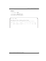
TABLE OF CONTENTS
Part I: Introduction and Initial Setup ___________________________1
Chapter 1: Avidia System Configuration and Management Overview_______________ 3
Configuration Features ........................................................................................................4
Performance Monitoring Features .......................................................................................6
System Administration and Diagnostic Features ................................................................ 7
Avidia System File Management ........................................................................................8
Restoring System Files..........................................................................................8
How Image Files are Used ....................................................................................8
How Configuration Files are Used........................................................................8
How Hardware Profile Files are Used ..................................................................9
Management Tools and Protocols .......................................................................................9
Chapter 2: Preparing for System Configuration and Management ________________ 11
Step 1: Connect a Terminal and Log On ...........................................................................12
Step 2: Set the Management Card IP Addresses ...............................................................13
Setting the System IP Address, Subnet Mask and Default Gateway ..................13
Setting the Gateway IP Address..........................................................................14
Displaying the System IP Addresses................................................................... 14
Step 3: Select a Management Interface .............................................................................15
Step 4: Select an Access Method and Complete Setup .....................................................15
Accessing the Command-line Interface .............................................................. 15
Accessing the Web Interface...............................................................................16
Next Steps..........................................................................................................................17
Avidia System Configuration and Management User Manual
vii
Table of Contents
Chapter 3: Applications and Configuration Overview ___________________________19
ATM...................................................................................................................................20
ATM Traffic Configuration.................................................................................20
ATM Traffic Management ..................................................................................22
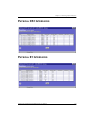
ATM Device Addresses ......................................................................................23
ATM Virtual Circuits ..........................................................................................24
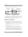
Frame Relay Transmission ................................................................................................26
SONET...............................................................................................................................28
Redundancy .......................................................................................................................28
Dual Homing .......................................................................................................29
Line Card Redundancy ........................................................................................32
Automatic Protection Switching .........................................................................33
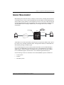
Inband Management ..........................................................................................................35
Inband to Avidia ..................................................................................................36
Inband to Modems...............................................................................................36
Inband for Subtending .........................................................................................37
Bridging and Routing.........................................................................................................37
Bridging and Spanning Tree Protocol .................................................................38
Routing ................................................................................................................38
Encapsulation for Bridging, Routing, or Brouting ..............................................39
Implementing Bridging/Routing/Brouting Sessions ...........................................41
Downloading Files to a Modem.........................................................................................44
Transparent LAN Service ..................................................................................................44
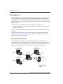
Subtending Multiple Systems ............................................................................................45
Star Management.................................................................................................48
Daisy Chain Management ...................................................................................52
viii
Avidia System Configuration and Management User Manual
Table of Contents
OAM Alarms and Loopbacks............................................................................................57
About Alarm Surveillance................................................................................... 57
About ATM Loopbacks ......................................................................................58
OAM Location ID ............................................................................................... 59
Preparing to Run OAM Loopbacks.....................................................................59
Example ATM-Layer Loopbacks .......................................................................61
After Running Loopbacks ................................................................................... 68
Avidia Alarm Manager ......................................................................................................69
Configuring Avidia System Information...........................................................................69
Setting Up Connections ..................................................................................................... 70
DS1 Line/Management Combination Card.........................................................70
Frame-based Services.......................................................................................... 71
Cell-based Services .............................................................................................74
Saving Configurations .......................................................................................................75
Part II: The Avidia Command-Line Interface ____________________77
Chapter 4: Introduction to the Command-Line Interface ________________________ 79
Logging On to the Command-Line Interface ....................................................................80
Understanding Command-Line Interface Structure ..........................................................81
Navigating the Command-Line Interface ..........................................................................82
Command-Line Interface Conventions .............................................................................82
Getting Help ...................................................................................................................... 83
Logging Off the Command-Line Interface........................................................................ 83
Avidia System Configuration and Management User Manual
ix
Table of Contents
Chapter 5: Configuring System Parameters ___________________________________85
Configuring System Information .......................................................................................86
Configuring the System Name ............................................................................86
Configuring the System Contact .........................................................................87
Configuring the System Location........................................................................88
Configuring the System Date and Time ..............................................................89
Configuring Boot File Information .....................................................................90
Displaying System Information...........................................................................91
Configuring IP Addresses..................................................................................................91
Configuring the System IP Address, Subnet Mask and Default Gateway ..........92
Configuring the Gateway IP Address..................................................................93
Displaying the System IP Addresses...................................................................93
Configuring Trap Generation Status..................................................................................94
Configuring Trap Receivers...............................................................................................95
Adding Trap Receivers........................................................................................95
Displaying Trap Receivers ..................................................................................96
Deleting Trap Receivers ......................................................................................96
Configuring Community Strings .......................................................................................97
Adding Community Strings.................................................................................97
Displaying Community Strings ...........................................................................98
Deleting Community Strings...............................................................................98
Chapter 6: Configuring Subscriber Services ___________________________________99
Configuring ADSL Line Profiles.....................................................................................100
Adding ADSL Line Profiles..............................................................................100
Displaying ADSL Line Profiles ........................................................................102
Deleting ADSL Line Profiles ............................................................................103
x
Avidia System Configuration and Management User Manual
Table of Contents
Configuring ADSL Alarm Profiles ................................................................................. 104
Adding ADSL Alarm Profiles........................................................................... 104
Displaying ADSL Alarm Profiles ..................................................................... 105
Deleting ADSL Alarm Profiles ......................................................................... 106
Configuring ADSL Handshaking .................................................................................... 107
Setting Handshaking Parameters....................................................................... 107
Displaying Handshaking Parameters ................................................................ 108
Configuring ADSL Service ............................................................................................. 109
Adding ADSL Port Configurations................................................................... 109
Displaying ADSL Port Configurations ............................................................. 110
Configuring SDSL Frame Line Profiles.......................................................................... 111
Adding SDSL Frame Line Profiles ................................................................... 112
Displaying SDSL Frame Line Profiles ............................................................. 112
Deleting SDSL Frame Line Profiles ................................................................. 113
Configuring SDSL Frame Alarm Profiles ....................................................................... 114
Adding SDSL Frame Alarm Profiles ................................................................ 114
Displaying SDSL Frame Alarm Profiles........................................................... 115
Deleting SDSL Frame Alarm Profiles .............................................................. 116
Configuring SDSL Frame Service................................................................................... 117
Adding SDSL Frame Port Configurations ........................................................ 117
Displaying SDSL Frame Port Configurations................................................... 118
Configuring SDSL Cell Line Profiles ............................................................................. 119
Adding SDSL Cell Line Profiles....................................................................... 119
Displaying SDSL Cell Line Profiles ................................................................. 120
Deleting SDSL Cell Line Profiles..................................................................... 121
Configuring SDSL Cell Alarm Profiles .......................................................................... 121
Adding SDSL Cell Alarm Profiles.................................................................... 122
Displaying SDSL Cell Alarm Profiles .............................................................. 123
Deleting SDSL Cell Alarm Profiles .................................................................. 124
Avidia System Configuration and Management User Manual
xi
Table of Contents
Configuring SDSL Cell Service ......................................................................................124
Adding SDSL Cell Port Configurations ............................................................125
Displaying SDSL Cell Port Configurations ......................................................126
Configuring IDSL Line Profiles ......................................................................................127
Adding IDSL Line Profiles ...............................................................................127
Displaying IDSL Line Profiles..........................................................................128
Deleting IDSL Line Profiles..............................................................................129
Configuring IDSL Alarm Profiles ...................................................................................130
Adding IDSL Alarm Profiles ............................................................................130
Displaying IDSL Alarm Profiles .......................................................................131
Deleting IDSL Alarm Profiles...........................................................................133
Configuring IDSL Service ...............................................................................................133
Modifying the IDSL Transmit Clock Source ....................................................134
Displaying the IDSL Transmit Clock Source....................................................134
Modifying IDSL Port Configurations ...............................................................135
Displaying IDSL Port Configurations ...............................................................136
Configuring xDSL Subscriber Names .............................................................................138
Chapter 7: Configuring Network Services ____________________________________141
Configuring OC3 Service ................................................................................................142
Configuring the OC3 Interface Type.................................................................142
Displaying the Configured OC3 Interface Type ...............................................143
Configuring DS1 Service.................................................................................................143
Configuring DS1 Ports ......................................................................................144
Displaying DS1/T1 Port Configurations ...........................................................146
Configuring DS3 Service.................................................................................................149
Configuring DS3 Ports ......................................................................................149
Displaying DS3 Port Configurations.................................................................150
xii
Avidia System Configuration and Management User Manual
Table of Contents
Chapter 8: Configuring ATM Virtual Circuits ________________________________ 153
Configuring ATM Traffic Profiles .................................................................................. 154
Adding ATM Traffic Profiles ........................................................................... 155
Displaying ATM Traffic Profiles...................................................................... 156
Deleting ATM Traffic Profiles.......................................................................... 157
Configuring APS ............................................................................................................. 158
Configuring APS ............................................................................................... 158
Issuing Manual APS Commands ...................................................................... 159
Displaying APS Configuration ......................................................................... 160
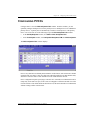
Configuring PVPCs ......................................................................................................... 162
Viewing ATM Port Settings.............................................................................. 162
Configuring Cell Channel Card PVPCs............................................................ 163
Changing Cell Channel Card PVPC Admin Status........................................... 167
Deleting Primary and Backup Cell Channel Card PVPCs................................ 168
Displaying Cell Channel Card PVPC Information ........................................... 169
Configuring PVCCs......................................................................................................... 170
Configuring Cell Channel Card PVCCs ........................................................... 171
Configuring Frame Channel Card PVCCs ........................................................ 179
Configuring SPVCs ......................................................................................................... 188
Adding SPVCs .................................................................................................. 189
Changing SPVC Admin Status ......................................................................... 190
Displaying SPVCs............................................................................................. 191
Displaying SPVC Details.................................................................................. 193
Deleting SPVCs ................................................................................................ 194
Restarting SPVCs.............................................................................................. 195
Avidia System Configuration and Management User Manual
xiii
Table of Contents
Configuring ATM Routing ..............................................................................................196
Adding ATM Routing Table Entries.................................................................196
Displaying ATM Routing Table Entries ...........................................................197
Changing ATM Routing Admin Status.............................................................199
Deleting ATM Routing Table Entries ...............................................................199
Configuring ATM Policing..............................................................................................200
ATM Port Policing ............................................................................................200
PVC Policing .....................................................................................................201
PVP Policing .....................................................................................................202
Chapter 9: Configuring Frame Relay Interworking ____________________________205
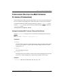
Configuring Frame Relay Links ......................................................................................206
Adding a Frame Relay Link ..............................................................................206
Modifying Frame Relay Link Settings ..............................................................207
Deleting Frame Relay Links..............................................................................209
Displaying Frame Relay Link Settings .............................................................210
Configuring Frame Relay FRF.8 Circuits........................................................................211
Adding a Frame Relay FRF.8 Circuit ...............................................................212
Modifying Frame Relay FRF.8 Circuit Parameters ..........................................215
Deleting Frame Relay FRF.8 Circuits ...............................................................217
Displaying Frame Relay FRF.8 Circuit Settings...............................................217
Configuring Frame Relay FRF.5 Circuits........................................................................219
Adding a Frame Relay FRF.5 Circuit ...............................................................220
Modifying Frame Relay FRF.5 Circuit Parameters ..........................................222
Deleting Frame Relay FRF.5 Circuits ...............................................................224
Displaying Frame Relay FRF.5 Circuit Settings...............................................225
xiv
Avidia System Configuration and Management User Manual
Table of Contents
Chapter 10: Configuring Bridging and Routing _______________________________ 227
Configuring Bridging and Routing Sessions ................................................................... 228
Adding Sessions ................................................................................................ 228
Modifying Sessions ........................................................................................... 230
Displaying Sessions .......................................................................................... 233
Deleting Sessions .............................................................................................. 235
Configuring IP Routing ................................................................................................... 235
Adding IP Routing Table Entries...................................................................... 236
Displaying the IP Routing Table....................................................................... 236
Deleting IP Routing Table Entries .................................................................... 239
Configuring IP ARP ........................................................................................................ 239
Adding IP ARP Table Entries ........................................................................... 240
Displaying the IP ARP Table............................................................................ 240
Deleting IP ARP Table Entries ......................................................................... 241
Modifying RIP Configuration ......................................................................................... 242
Modifying RIP .................................................................................................. 242
Displaying the RIP Configuration Table........................................................... 243
Configuring Destination-MAC Address Filtering (Forwarding) .................................... 245
Adding Destination-MAC Address Filtering Table Entries.............................. 245
Displaying the Destination-MAC Address Filtering Table .............................. 246
Deleting Destination-MAC Address Filtering Table Entries............................ 247
Configuring System Bridging Parameters....................................................................... 247
Modifying System Bridging Parameters........................................................... 248
Displaying System Bridging Parameters .......................................................... 248
Configuring System STP Parameters .............................................................................. 249
Modifying System STP Parameters .................................................................. 249
Displaying System STP Parameters.................................................................. 250
Avidia System Configuration and Management User Manual
xv
Table of Contents
Configuring Global IP Routing Settings..........................................................................251
Configuring Global IP Routing Settings ...........................................................251
Displaying Global IP Routing Settings .............................................................251
Chapter 11: Configuring Subtended Systems _________________________________253
Adding a Subtended System ............................................................................................254
Modifying a Subtended System Configuration ...............................................................255
Displaying Subtending Information.................................................................................257
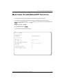
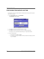
Chapter 12: Monitoring Subscriber Connections ______________________________259
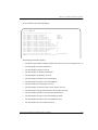
Monitoring ADSL Performance ......................................................................................260
Monitoring ADSL Loop Status .........................................................................260
Monitoring ADSL Performance History ...........................................................262
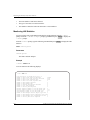
Monitoring SDSL Frame Performance............................................................................264
Displaying SDSL Frame Line Statistics............................................................264
Displaying SDSL Frame Performance History .................................................266
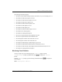
Monitoring SDSL Frame CPE Statistics .........................................................................267
Monitoring SDSL Cell Performance ...............................................................................268
Displaying SDSL Cell Line Statistics ...............................................................268
Displaying SDSL Cell Performance History.....................................................270
Displaying SDSL Cell TC Layer Statistics .......................................................271
Clearing SDSL Cell Statistics ...........................................................................273
Monitoring IDSL Current Performance...........................................................................274
Monitoring IDSL Current Performance ............................................................274
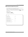
Chapter 13: Monitoring Network Connections ________________________________277
Monitoring SONET Performance....................................................................................278
Monitoring SONET Medium Statistics .............................................................278
Monitoring SONET Section Statistics ..............................................................280
Monitoring SONET Line Statistics ...................................................................281
Monitoring SONET Path Statistics ...................................................................283
xvi
Avidia System Configuration and Management User Manual
Table of Contents
Monitoring DS1/T1 Performance.................................................................................... 286
Monitoring DS3 Performance ......................................................................................... 289
Monitoring ATM Connection Statistics .......................................................................... 292
ATM PVCC Connection Statistics.................................................................... 292
ATM PVPC Connection Statistics .................................................................... 293
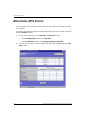
Monitoring APS Status.................................................................................................... 295
Monitoring Frame Relay Performance Statistics ............................................................ 296
Monitoring Link Statistics................................................................................. 296
Monitoring LMI Statistics................................................................................. 298
Monitoring Circuit Statistics ............................................................................. 299
Monitoring FRF.5 Statistics .............................................................................. 302
Monitoring FRF.8 Statistics .............................................................................. 303
Chapter 14: Monitoring Bridging and Routing ________________________________ 305
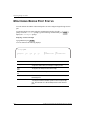
Monitoring Bridge Port Status......................................................................................... 306
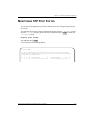
Monitoring STP Port Status............................................................................................. 307
Monitoring System Bridge/STP Statistics....................................................................... 309
Monitoring System IP Statistics ...................................................................................... 311
Monitoring Bridge Forwarding Statistics ........................................................................ 313
Chapter 15: Monitoring Physical Interfaces __________________________________ 315
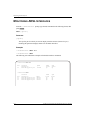
Monitoring ADSL Interfaces........................................................................................... 316
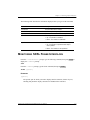
Monitoring SDSL Frame Interfaces ................................................................................ 317
Monitoring SDSL Cell Interfaces.................................................................................... 319
Monitoring DS1 Interfaces .............................................................................................. 320
Monitoring DS3 Interfaces .............................................................................................. 322
Monitoring OC3 Interfaces.............................................................................................. 324
Monitoring Interfaces ...................................................................................................... 325
Avidia System Configuration and Management User Manual
xvii
Table of Contents
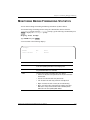
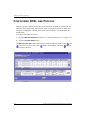
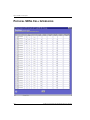
Chapter 16: Monitoring System Alarms and Status ____________________________327
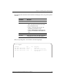
Monitoring System Alarms and Events ...........................................................................328
Monitoring SDSL Frame Alarms ....................................................................................331
Monitoring SDSL Frame Alarm Status.............................................................331
Monitoring SDSL Frame Alarm History...........................................................333
Monitoring SDSL Cell Alarms ........................................................................................334
Monitoring IDSL Alarm Status .......................................................................................337
Monitoring System Hardware Status...............................................................................339
Chapter 17: System Maintenance and Administration __________________________341
Configuring and Initiating OAM Loopbacks...................................................................342
Setting the System OAM Source Location ID ..................................................342
Configuring and Initiating OAM Loopbacks ....................................................343
Initiating Communication Path Loopbacks .....................................................................345
Initiating OC3 Loopbacks .................................................................................346
Initiating DS1 Loopbacks..................................................................................346
Initiating DS3 Loopbacks..................................................................................347
Managing IDSL Diagnostics ...........................................................................................348
Clearing Statistics..............................................................................................348
Configuring and Initiating IDSL Loopbacks.....................................................349
Configuring and Initiating Corrupted CRCs .....................................................350
Displaying IDSL Loopback and Corrupted CRC Test Configurations.............351
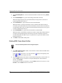
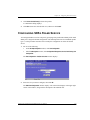
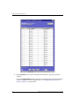
Detecting Network Devices .............................................................................................353
Managing Image Files .....................................................................................................354
Uploading Files to a TFTP Server.....................................................................354
Downloading Files from a TFTP Server ...........................................................355
Copying Files ....................................................................................................356
Displaying a Directory of Files on a Card.........................................................357
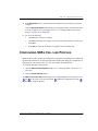
Downloading Files to a Modem.......................................................................................358
xviii
Avidia System Configuration and Management User Manual
Table of Contents
Managing Security........................................................................................................... 359
Adding User Accounts ...................................................................................... 359
Displaying User Accounts................................................................................. 361
Modifying User Accounts ................................................................................. 361
Deleting User Accounts .................................................................................... 363
Changing a User Password................................................................................ 364
Displaying System Inventory .......................................................................................... 364
Viewing SDSL Frame CPE general information ............................................................ 365
Rebooting Cards .............................................................................................................. 366
Rebooting the System ....................................................................................... 366
Rebooting an Individual Card ........................................................................... 367
Setting the Command-Line Interface Timeout Option.................................................... 367
Deleting Files................................................................................................................... 368
Part III: The Avidia Web Interface ___________________________369
Chapter 18: Introduction to the Web Interface________________________________ 371
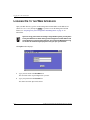
Logging On to the Web Interface .................................................................................... 372
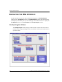
Navigating the Web Interface.......................................................................................... 374
Site Map Navigation Window........................................................................... 374
Tree Navigation Window.................................................................................. 375
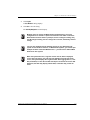
Web Interface Conventions ............................................................................................. 376
Getting Help .................................................................................................................... 376
Logging Off the Web Interface ....................................................................................... 376
Chapter 19: Configuring System Parameters _________________________________ 377
Configuring System Identification .................................................................................. 380
Configuring Management Card IP Addresses ................................................................. 381
Configuring System Trap Generation Status................................................................... 382
Configuring Boot File Information ................................................................................. 382
Configuring System Date and Time ................................................................................ 384
Avidia System Configuration and Management User Manual
xix
Table of Contents
Chapter 20: Configuring Subscriber Services _________________________________385
Configuring ADSL Line Profiles.....................................................................................386
Configuring ADSL Alarm Profiles..................................................................................388
Configuring ADSL Service .............................................................................................391
Configuring SDSL Frame Line Profiles ..........................................................................393
Adding SDSL Frame Line Profiles ...................................................................394
Deleting SDSL Frame Line Profiles .................................................................394
Configuring SDSL Frame Alarm Profiles .......................................................................395
Adding SDSL Frame Alarm Profiles ................................................................395
Deleting SDSL Frame Alarm Profiles...............................................................396
Configuring SDSL Frame Service...................................................................................397
Configuring SDSL Cell Line Profiles..............................................................................399
Adding SDSL Cell Line Profiles.......................................................................400
Deleting SDSL Cell Line Profiles .....................................................................401
Configuring SDSL Cell Alarm Profiles...........................................................................401
Adding SDSL Cell Alarm Profiles ....................................................................402
Deleting SDSL Cell Alarm Profiles ..................................................................403
Configuring SDSL Cell Service ......................................................................................404
Configuring IDSL Line Profiles ......................................................................................406
Adding IDSL Line Profiles ...............................................................................407
Deleting IDSL Line Profiles..............................................................................408
Configuring IDSL Alarm Profiles ...................................................................................408
Adding IDSL Alarm Profiles ............................................................................409
Deleting IDSL Alarm Profiles...........................................................................410
Configuring IDSL Service ...............................................................................................411
Chapter 21: Configuring Network Services ___________________________________415
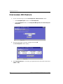
Configuring OC3 Service ................................................................................................416
Configuring DS1 Service.................................................................................................417
Configuring DS3 Service.................................................................................................422
xx
Avidia System Configuration and Management User Manual
Table of Contents
Chapter 22: Configuring ATM Virtual Circuits _______________________________ 427
Configuring ATM Traffic Profiles .................................................................................. 428
Adding ATM Traffic Profiles ........................................................................... 429
Deleting ATM Traffic Profiles.......................................................................... 430
Configuring APS ............................................................................................................. 430
Configuring APS ............................................................................................... 431
Issuing Manual APS Commands ...................................................................... 432
Configuring PVPCs ......................................................................................................... 433
Adding Primary PVPCs .................................................................................... 434
Changing PVPC Admin Status ......................................................................... 437
Deleting PVPCs ................................................................................................ 438
Adding Backup PVPCs ..................................................................................... 439
Deleting Backup PVPCs ................................................................................... 441
Returning Service from a Backup PVPC to a Primary PVPC .......................... 442
Configuring PVCCs......................................................................................................... 443
Adding Primary PVCCs .................................................................................... 444
Changing PVCC Admin Status ......................................................................... 448
Deleting PVCCs ................................................................................................ 449
Adding Backup PVCCs..................................................................................... 450
Deleting Backup PVCCs................................................................................... 452
Returning Service from a Backup PVCC to a Primary PVCC ......................... 453
Configuring SPVCs ......................................................................................................... 454
Configuring ATM Routing.............................................................................................. 457
Configuring ATM Interface Information ........................................................................ 460
Configuring ATM Policing ............................................................................................. 462
ATM Port Policing ............................................................................................ 462
PVCC Policing .................................................................................................. 464
PVPC Policing .................................................................................................. 465
Avidia System Configuration and Management User Manual
xxi
Table of Contents
Chapter 23: Configuring Frame Relay Interworking ___________________________467
The Frame Relay Interworking Configuration Table ......................................................468
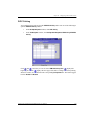
Adding a Frame Relay Configuration..............................................................................470
Modifying a Frame Relay Configuration.........................................................................475
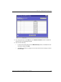
Viewing an Entire Frame Relay Configuration ...............................................................478
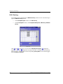
Deleting a Frame Relay Configuration............................................................................483
Chapter 24: Configuring Bridging and Routing _______________________________485
Configuring Bridging and Routing Sessions ...................................................................486
Adding Sessions ................................................................................................488
Modifying Sessions ...........................................................................................491
Deleting Sessions ..............................................................................................493
Configuring Router Groups .............................................................................................493
Adding Router Groups ......................................................................................494
Deleting Router Groups.....................................................................................494
Configuring IP Routing ...................................................................................................495
Adding IP Routing Table Entries ......................................................................496
Deleting IP Routing Table Entries ....................................................................497
Modifying RIP Configuration..........................................................................................497
Configuring System Bridging and STP Parameters ........................................................500
Modifying System Bridging Parameters ...........................................................501
Modifying System STP Parameters ..................................................................502
Configuring Global IP Routing Settings..........................................................................502
Chapter 25: Monitoring Subscriber Connections ______________________________505
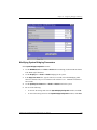
Monitoring ADSL Status .................................................................................................506
Monitoring SDSL Frame Current Statistics.....................................................................510
Monitoring SDSL Cell Performance ...............................................................................512
Monitoring IDSL Performance........................................................................................515
xxii
Avidia System Configuration and Management User Manual
Table of Contents
Chapter 26: Monitoring Network Connections ________________________________ 517
Monitoring SONET Performance.................................................................................... 518
Medium/Section/Line Current Performance ..................................................... 518
Path Current Performance ................................................................................. 522
Monitoring DS1 Performance ......................................................................................... 524
Monitoring E1 Performance ............................................................................................ 527
Monitoring DS3 Performance ......................................................................................... 530
Monitoring APS Status.................................................................................................... 532
Chapter 27: Monitoring Physical Interfaces __________________________________ 535
Opening the Interface Window........................................................................................ 536
Physical SONET Interfaces ............................................................................................. 538
Physical ADSL Interfaces ............................................................................................... 538
Physical SDSL Frame Interfaces..................................................................................... 539
Physical SDSL Cell Interfaces ........................................................................................ 540
Physical DS1 Interfaces................................................................................................... 541
Physical E1 Interfaces ..................................................................................................... 541
Physical DS3 Interfaces................................................................................................... 542
Chapter 28: Monitoring System Alarms and Status ____________________________ 543
Monitoring System Events .............................................................................................. 544
Monitoring System Alarms ............................................................................................. 546
Monitoring SDSL Frame Alarms .................................................................................... 549
Monitoring SDSL Cell Alarms........................................................................................ 551
Monitoring IDSL Alarm Status ....................................................................................... 553
Chapter 29: System Maintenance and Administration__________________________ 557
Configuring and Initiating OAM Loopbacks .................................................................. 558
Initiating Communication Path Loopbacks ..................................................................... 563
OC3 Loopbacks................................................................................................. 565
DS1 Loopbacks ................................................................................................. 566
DS3 Loopbacks ................................................................................................. 567
Avidia System Configuration and Management User Manual
xxiii
Table of Contents
Managing IDSL Diagnostics ...........................................................................................568
Detecting Network Devices .............................................................................................570
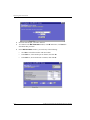
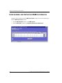
Managing Image Files .....................................................................................................571
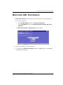
Uploading Files to a TFTP Server.....................................................................572
Downloading Files to the Avidia System..........................................................573
Copying Files ....................................................................................................576
Deleting Files ....................................................................................................577
Downloading Files to a Modem.......................................................................................577
Managing Security ...........................................................................................................580
Adding User Accounts ......................................................................................582
Deleting User Accounts.....................................................................................584
Modifying User Accounts .................................................................................584
Restoring the Admin Account Password...........................................................586
Configuring the System Timers.......................................................................................586
Setting the Inactivity Timeout ...........................................................................587
Setting the Refresh Rate ....................................................................................588
Displaying System Inventory...........................................................................................588
Resetting Cards ................................................................................................................589
Activating and Deactivating Ports ...................................................................................590
Part IV: Appendixes ______________________________________ 593
Appendix A: Troubleshooting and Diagnostics ________________________________595
Accessing the Boot Monitor ............................................................................................595
Downloading an Image File from a TFTP Server ...........................................................596
Booting the System ..........................................................................................................598
Performing System Diagnostics.......................................................................................599
Detecting PCI Devices ......................................................................................599
Performing NAND EEPROM Diagnostics .......................................................599
Testing the TRAM CUBIT................................................................................600
Setting the System Date and Time...................................................................................601
xxiv
Avidia System Configuration and Management User Manual
Table of Contents
Appendix B: Contacting ADC ______________________________________________ 603
Technical Support............................................................................................................ 603
World Wide Web............................................................................................................. 603
Limited Warranty ............................................................................................................ 603
Advance Replacement ..................................................................................................... 604
Billing .............................................................................................................................. 605
Returns............................................................................................................................. 605
Appendix C: SPVC Last Release Cause Codes_________________________________ 607
Appendix D: Glossary _____________________________________________________ 611
Index_______________________________________________________________________ 617
Avidia System Configuration and Management User Manual
xxv
Table of Contents
xxvi
Avidia System Configuration and Management User Manual
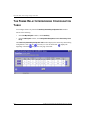
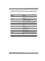
PART I
INTRODUCTION AND INITIAL SETUP
This section contains the following chapters, which provide an overview of Avidia system
configuration and management and specific instructions for preparing to configure and manage
a system.
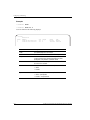
Chapter Number
Chapter Title
Page
1
Avidia System Configuration and Management Overview
3
2
Preparing for System Configuration and Management
11
3
Applications and Configuration Overview
19
Avidia System Configuration and Management User Manual
1
2
Avidia System Configuration and Management User Manual
AVIDIA SYSTEM CONFIGURATION
AND MANAGEMENT OVERVIEW
1
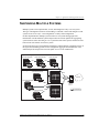
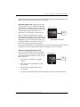
Each Avidia® system provides two different user interfaces for system configuration and
management. Both interfaces are preinstalled on the management card.
The command-line interface provides comprehensive system configuration and management
features using a text-only interface. You access the command-line interface using either an
ASCII terminal or a PC running a terminal emulation program, connected to the management
card craft port. Once the management card IP address is configured, you can also access the
command-line interface remotely using a telnet application. The command-line interface
contains a hierarchy of different prompts, at which you type commands to perform a particular
configuration or management task.
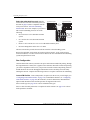
The Web interface is a graphical user interface (GUI) that provides the most of the system
configuration and management features in the command-line interface, as well as additional
security features. You access the Web interface using a PC connected to the Fast Ethernet port
on the back of the Avidia chassis, or over a network. The Web interface provides two different
styles of navigation — the Site Map Navigation window and the Tree Navigation window. From
either navigation window, you select the configuration or management task you want to
perform.
Avidia System Configuration and Management User Manual
3
Configuration Features
CONFIGURATION FEATURES
The Avidia system enables you to configure:
4
•
system information, such as system name and location, contact, date and time
•
management card IP address, subnet mask, and default gateway
•
trap receivers and trap generation status
•
community strings
•
ATM traffic profiles that define the traffic type and Quality of Service (QoS) on a specific
channel. ATM traffic profiles are applied to permanent Virtual Channel Connections
(VCCs) and Virtual Path Connections (VPCs) during configuration.
•
ATM VCC, VPC, and port policing
•
bridging and routing sessions
•
Frame Relay traffic profiles that define the traffic type and Quality of Service (QoS) on a
specific channel. Frame Relay traffic profiles are applied to Permanent Virtual Channels
(PVCs) during configuration. You can also specify either FRF.5 or FRF.8 interworking.
•
ADSL cell-based card line profiles that define the rate mode, target margin, minimum and
maximum interleave transmit rate, and interleave depth. ADSL line profiles are applied to
ADSL channels during configuration.
•
ADSL cell-based card alarm profiles that define the Loss Of Frame (LOF), Loss Of Signal
(LOS) and Errored Seconds (ES) thresholds. ADSL alarm profiles are applied to ADSL
channels during configuration.
•
SDSL cell-based card line profiles that define the rate mode, target margin, minimum and
maximum interleave transmit rate, and interleave depth. SDSL cell line profiles are applied
to cell-based SDSL channels during configuration.
•
SDSL cell-based card alarm profiles that define the Loss Of Frame (LOF), Loss Of Signal
(LOS) and Errored Seconds (ES) thresholds. ADSL alarm profiles are applied to ADSL
channels during configuration.
Avidia System Configuration and Management User Manual
Chapter 1: Avidia System Configuration and Management Overview
•
SDSL frame-based card line profiles that define the transmission rate. SDSL line profiles
are applied to SDSL channels during configuration.
•
SDSL frame-based card alarm profiles that enable or disable margin, ES, Unavailable
Seconds (UAS) and Loss of Sync Word (LOSW) alarms and define the alarm thresholds.
SDSL alarm profiles are applied to SDSL channels during configuration.
•
IDSL frame-based card line profiles that define the transmission rate. SDSL line profiles
are applied to SDSL channels during configuration.
•
IDSL frame-based card alarm profiles that enable or disable margin, ES, Unavailable
Seconds (UAS) and Loss of Sync Word (LOSW) alarms and define the alarm thresholds.
IDSL alarm profiles are applied to IDSL channels during configuration.
•
ADSL cell-based service, including assigning ADSL line and ADSL alarm profiles
•
SDSL cell-based service, including assigning cell-based SDSL line and SDSL alarm
profiles
•
SDSL frame-based service, including assigning frame-based SDSL line and SDSL alarm
profiles
•
IDSL frame-based service, including assigning IDSL line and IDSL alarm profiles
•
xDSL subscriber names to identify the subscriber to which each port is connected
•
ATM service, including setting up cell channel card VCCs and VPCs, and frame channel
card (SDSL frame-based and IDSL) VCCs
•
Frame Relay service, including setting up PVCs for IDSL card
•
OC3 service (SONET or SDH), with Automatic Protection Switching (APS)
•
DS1/T1 service, including specifying line type, line code, circuit identifier, line length,
clocking type, and enabling or disabling DS1/T1 traps
•
DS3 service, including specifying line type, line length, clocking type, and enabling or
disabling DS3 traps
Avidia System Configuration and Management User Manual
5
Performance Monitoring Features
PERFORMANCE MONITORING FEATURES
The Avidia system enables you to display or monitor system status. The following status can be
seen through the Avidia command-line interface:
6
•
ATM PVC and PVP connection statistics
•
APS status
•
bridge and STP port status
•
system bridge/STP statistics, including bridge forwarding statistics
•
system IP statistics
•
ADSL loop status and performance history
•
SDSL cell statistics and performance history
•
SDSL frame statistics and performance history
•
IDSL statistics and performance history
•
SDSL CPE statistics
•
SONET status and performance history, by Medium, Section, Line and Path
•
DS1/T1 status and performance history
•
DS3 status and performance history
•
system physical interface statistics, all at once or by slot
•
ATM cell switch interfaces
•
system log
•
system alarms and event status
•
SDSL alarm history
•
IDSL alarm status
Avidia System Configuration and Management User Manual
Chapter 1: Avidia System Configuration and Management Overview
The following status can be seen through the Avidia Web interface:
•
•
statistics
–
IDSL current performance
–
SONET medium/section/line
–
SONET path
–
DS1 current performance
–
DS3 current performance
–
physical slot interfaces
current status
–
ADSL loop status
–
SDSL frame loop status
–
SDSL cell loop status
SYSTEM ADMINISTRATION AND DIAGNOSTIC
FEATURES
The Avidia system enables you to perform the following administrative functions:
•
copying, deleting and displaying a directory of files using a DOS-like file system
•
uploading files to and downloading files from a TFTP server
•
downloading files to modems
•
displaying system inventory, including hardware serial numbers and software version
numbers
•
viewing CPE general information
•
rebooting individual cards
•
setting the system time-out value and Web-Based Interface performance data refresh rate
•
activating and deactivating ports
•
configuring and initiating OAM F4 and F5 flow loopbacks
•
APS configuration and status
•
IDSL diagnostics
Avidia System Configuration and Management User Manual
7
Avidia System File Management
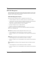
AVIDIA SYSTEM FILE MANAGEMENT
Each Avidia line, channel, and management card ships with the necessary system files
preinstalled in NVRAM (Non-Volatile Random Access Memory).
Restoring System Files
To restore system files for a card, copy a complete set of system files from the Avidia
MuxWare™ CD-ROM to that card. See “Managing Image Files” on page 354 for
command-line interface instructions or “Managing Image Files” on page 571 for Web interface
instructions.
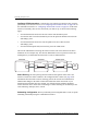
How Image Files are Used
Each card in the Avidia system contains its own image files, which are stored in NVRAM and
have a .bin file name extension. Image files contain the firmware and software required to use
the hardware on which they reside. When you boot the Avidia system, each card runs a
bootstrap program that retrieves the image file out of NVRAM, decompresses it, then loads it
into Random Access Memory (RAM). The firmware runs from RAM during system operation.
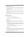
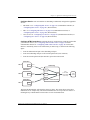
How Configuration Files are Used
All configuration information for the Avidia system is stored permanently in the management
card NVRAM. There is a separate ASCII configuration file for each card. The files are named
SnnCxxxx.cnf, where nn is the slot number and xxxx is the part number for that card.
During system startup, each line card and channel card retrieves its configuration file from the
management card and stores the information in RAM. If the management card is not installed,
or is not functioning, the line cards and channel cards can not boot.
If you remove a line or channel card and replace it with a new card of the same type, the new
card automatically loads the previous card’s configuration file from the management card into
RAM. To configure the new card differently, use one of the management interfaces to delete the
existing configuration then configure the card as desired. If you remove a line or channel card
and replace it with a new card of a different type, the card will not load the previous
configuration file.
8
Avidia System Configuration and Management User Manual
Chapter 1: Avidia System Configuration and Management Overview
If you replace a management card, you can save the configuration files stored in the line and
channel card RAM to the management card NVRAM. However, the management card
configuration file containing all of the system profile information will be lost. Therefore, before
replacing a management card, back up all of the configuration files from NVRAM, then restore
the files onto the new management card.
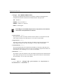
As soon as you make configuration changes, the information is saved to RAM
on the management card and each of the cards affected by the configuration.
The changes are lost if you unplug or reboot the management card or any of
the cards affected by the configuration before you save the configuration
changes to NVRAM. You must proactively save the configuration change to the
management card NVRAM using the Save command in either the Web interface
or the command-line interface.
How Hardware Profile Files are Used
A hardware profile text file (for example, amcprof.txt) is stored on each line, channel and
management card. This file contains the hardware serial numbers and version numbers for the
card. You can view this information using the command-line interface (see “Displaying System
Inventory” on page 364) or the Web interface (see “Displaying System Inventory” on
page 588). You cannot edit this information.
MANAGEMENT TOOLS AND PROTOCOLS
Avidia systems use the following management tools and protocols, which enable you to perform
management tasks such as system configuration and performance monitoring:
•
SNMP (Simple Network Management Protocol)
•
TFTP (Trivial File Transfer Protocol)
•
FTP (File Transfer Protocol)
•
Telnet (for command-line interface access)
•
HTTP (HyperText Transfer Protocol - for Web interface access)
•
MIBs (Management Information Bases)
•
Traps
Avidia System Configuration and Management User Manual
9
Management Tools and Protocols
10
Avidia System Configuration and Management User Manual
PREPARING FOR SYSTEM
CONFIGURATION AND
MANAGEMENT
2
Follow these steps to prepare for initial Avidia system configuration. To configure an Avidia
system that is already in service, begin with Step 3.
1
Connect a terminal or PC running terminal emulation software to the management card
craft port. See “Step 1: Connect a Terminal and Log On” on page 12.
2
Use the Avidia command-line interface to set the management card IP address. See “Step
2: Set the Management Card IP Addresses” on page 13.
3
Determine whether you want to use the command-line interface or the Web interface to
configure and manage the system. See “Step 3: Select a Management Interface” on page 15.
4
Determine which method you want to use to access the selected management interface. See
“Step 4: Select an Access Method and Complete Setup” on page 15.
Avidia System Configuration and Management User Manual
11
Step 1: Connect a Terminal and Log On
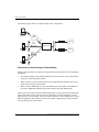
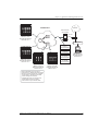
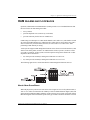
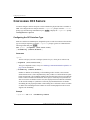
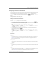
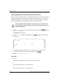
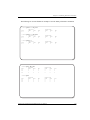
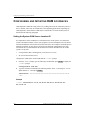
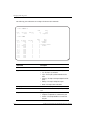
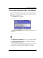
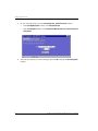
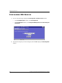
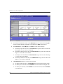
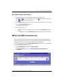
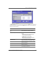
STEP 1: CONNECT A TERMINAL AND LOG ON
The first step in an initial Avidia system configuration is to set up a local connection to
the command-line interface. You access the command-line interface locally by connecting
either an ASCII terminal or a PC running a terminal emulation program to the management
card craft port.
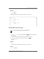
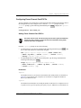
1
Connect one end of an RS-232 DB9 cable to the serial port on an ASCII terminal or PC,
then connect the other end of the cable to the craft port on the front of the Avidia
management card.
Refer to your system Hardware Installation Manual for help locating the management card
craft port and for cabling pinouts.
2
Power up the ASCII terminal or PC.
3
If you are using a PC as a terminal, run a terminal emulation program such as
HyperTerminal or ProComm.
See the terminal emulation program documentation for instructions.
4
Configure your terminal or PC terminal emulation program as follows:
•
baud rate: 9600 bps
•
data bits: 8
•
parity: none
•
stop bits: 1
•
flow control: none
5
If you are using a PC, in the terminal emulation program select the COM setting of the port
to which the RS-232 cable is connected (for example, COM1 or COM2).
6
Press
7
Type your user name, then press
ENTER
to initiate the terminal session and display the username: prompt.
ENTER .
The user name admin is preconfigured for your use.
The Password prompt displays.
8
Type your password, then press
ENTER .
The password for the preconfigured admin user name is dslam.
The system displays a list of general commands and navigational tips, followed by the
::root=> prompt.
12
Avidia System Configuration and Management User Manual
Chapter 2: Preparing for System Configuration and Management
STEP 2: SET THE MANAGEMENT CARD IP
ADDRESSES
You set the management card IP address, subnet mask and default gateway (if one exists) to
enable communication with external networks and to enable access to the Web interface.
You cannot use IP addresses 192.168.1.0 through 192.168.21.255 with subnet
mask 255.255.255.0 as these addresses are restricted for internal Avidia
system use. In addition, you cannot currently manage the Avidia system in a
supernetting environment in which the IP addressing scheme contains Class
C IP addresses with a Class B subnet mask.
You configure IP addresses from the ::ip=> prompt. From the ::root=> prompt, type the
configuration ip command then press ENTER to display the ::ip=> prompt.
configuration ip
Setting the System IP Address, Subnet Mask and Default Gateway
From the ::ip=> prompt, type the addr command in the following format then press
ENTER .
addr <ipaddr> [<netmask>] [<defaultroute>]
Parameters
<ipaddr>
The management card IP address for the Avidia system. This address is based on the
Ethernet network to which the Avidia system is attached (format xxx.xxx.xxx.xxx). The
default management card IP address is 192.168.0.1.
[<netmask>]
The subnet mask associated with the management card IP address, if a subnet exists. This
address is based on the Ethernet network to which the Avidia system is attached (format
xxx.xxx.xxx.xxx).
[<defaultroute>]
The IP address of a router on the Ethernet network through which the Avidia system can
communicate with external networks (format xxx.xxx.xxx.xxx).
Avidia System Configuration and Management User Manual
13
Step 2: Set the Management Card IP Addresses
Examples
::ip=> addr 192.168.0.1 255.255.255.0
::ip=> addr 192.168.0.1
::ip=> addr 192.168.0.1 255.255.255.0 192.168.0.100
Setting the Gateway IP Address
If a gateway exists on the network to which the Avidia system is attached and you did not
configure the gateway with the IP address, type the defaultroute command in the following
format then press ENTER .
defaultroute <gwaddr>
Parameter
<gwaddr>
The IP address of a router on the Ethernet network through which the Avidia system can
communicate with external networks (format xxx.xxx.xxx.xxx). The default gateway IP
address is 192.168.0.100.
Example
::ip=> defaultroute 192.168.0.100
Displaying the System IP Addresses
To verify your configuration, from the ::ip=> prompt, type show then press
screen similar to the following displays.
ENTER .
A
::ip=> show
AMC Card Ethernet Port IP Address:
AMC Card Ethernet Port IP Subnet Mask:
AMC Card Default Gateway:
14
192.168.0.1
255.255.255.0
192.168.0.100
Avidia System Configuration and Management User Manual
Chapter 2: Preparing for System Configuration and Management
STEP 3: SELECT A MANAGEMENT INTERFACE
You can perform most of the same system configuration and management functions using either
the command-line interface or the Web interface. However, you can only manage user accounts
using the Web interface. The command-line interface includes some on-screen help for basic
commands and navigation, while the Web interface offers a more comprehensive online Help
system to assist you.
The selection of an interface is based primarily on your personal preference. If you are more
comfortable entering series of commands at a system prompt than you are using GUI
applications, then you may want to use the command-line interface. If you are more comfortable
with GUI applications, you may find the Web interface easier to use.
STEP 4: SELECT AN ACCESS METHOD AND
COMPLETE SETUP
This section describes the ways in which you can access each of the management interfaces.
Accessing the Command-line Interface
Select one of the following methods of accessing the command-line interface then follow the
instructions to complete the setup:
•
Connect locally, using a terminal connected to the management card craft port (as described
in “Step 1: Connect a Terminal and Log On” on page 12).
•
Connect remotely, using a telnet program from any PC on the same network. To use the
Microsoft Windows® 95, Windows® 98 or Windows NT® telnet utility, type the following
command at a DOS prompt then press ENTER , where <ipaddress> is the Avidia
management card IP address (format xxx.xxx.xxx.xxx).
telnet <ipaddress>
The IP protocol stack must be installed on your PC to use the telnet utility. Refer to the
telnet documentation for additional instructions.
After the telnet session has been established, press
username: prompt.
Avidia System Configuration and Management User Manual
ENTER
to display the
15
Step 4: Select an Access Method and Complete Setup
Accessing the Web Interface
Using the Avidia Web interface requires:
•
a PC running Windows 95, Windows 98 or Windows NT, or a Solaris workstation
•
an Ethernet card installed in one of the expansion slots
•
Netscape® Version 4.5 or newer (recommended) or Internet Explorer® Version 4.0 or
newer
•
an Ethernet cable (straight-through if connecting the computer to a hub, cross-over if
connecting the computer directly to the Avidia system); see your Hardware Installation
Manual for cabling pinouts.
To access the Web interface:
1
16
Select one of the following methods of accessing the Web interface, then follow the
instructions to complete setup:
•
Connect locally, using a PC connected to the Avidia system Fast Ethernet port.
Connect one end of an Ethernet cable to the PC Ethernet port and the other end of the
cable to the Fast Ethernet port on the back of the Avidia chassis. Refer to your system
Hardware Installation Manual to locate the Fast Ethernet port on the back of the Avidia
chassis.
•
Connect remotely, using a PC on the same network.
2
If you have not already done so, plug the PC into a wall outlet then turn on the PC and
monitor.
3
Check the Ethernet card or adapter to make sure the link light is on, which confirms that
the Ethernet link is up.
Avidia System Configuration and Management User Manual
Chapter 2: Preparing for System Configuration and Management
4
To verify IP communications between the PC and the Avidia management card, do a ping
from the PC to the IP address of the Avidia management card.
To do a ping, from a DOS prompt, type the ping command in the following format then
press ENTER , where <ipaddress> is the Avidia management card IP address (format
xxx.xxx.xxx.xxx).
ping <ipaddress>
If the ping is successful, several reply messages display on the PC monitor. If the ping is
not successful, an error message displays, indicating that the request has timed out. If the
ping fails, make sure the Ethernet cable is securely connected to your PC and to the Avidia
system, and that you typed the correct IP address. Then try another ping.
5
Set the monitor screen resolution to a minimum of 800 x 600 dpi (dots per inch).
Refer to your operating system documentation for instructions on adjusting the screen
resolution.
NEXT STEPS
To use the command-line interface, go to “The Avidia Command-Line Interface” on page 77.
To use the Web interface, go to “The Avidia Web Interface” on page 369.
Avidia System Configuration and Management User Manual
17
Next Steps
18
Avidia System Configuration and Management User Manual
APPLICATIONS AND
CONFIGURATION OVERVIEW
3
This chapter provides overview information about applications and technologies used in the
Avidia system. Understanding the concepts discussed in this chapter will assist you during
system configuration.
For information about:
Go to page:
ATM
20
ATM Traffic Configuration
20
ATM Traffic Management
22
ATM Virtual Circuits
24
ATM Device Addresses
23
Frame Relay Transmission
26
SONET
28
Redundancy
28
Dual Homing
29
Line Card Redundancy
32
Automatic Protection Switching
33
Inband Management
35
Bridging and Routing
37
Downloading Files to a Modem
44
Transparent LAN Service
44
Subtending Multiple Systems
45
OAM Alarms and Loopbacks
57
Avidia Alarm Manager
69
Configuring Avidia System Information
69
Setting Up Connections
70
Saving Configurations
75
Avidia System Configuration and Management User Manual
19
ATM
ATM
The following sections provide information on setting up an ATM network.
ATM Traffic Configuration
ATM traffic profiles are preconfigured combinations of traffic descriptors and related
parameters, which define the traffic Quality of Service (QoS) contract. Traffic profiles are used
to configure virtual circuits (VCCs and VPCs). During virtual circuit configuration you assign
a traffic profile to each circuit. Therefore, you must configure the ATM traffic profiles prior to
configuring any virtual circuits.
Adding an ATM Traffic Descriptor Profile requires you to specify a traffic type. The following
table provides an explanation of the traffic types currently supported by the Avidia system.
20
Traffic Type
Description
Unspecified Bit Rate (UBR)
UBR is a best-effort service that is best suited for LAN traffic. When
traffic congestion occurs, data is dropped. The Avidia system also
offers UBR service that includes a peak cell rate.
Constant Bit Rate (CBR)
CBR is the highest quality of service, with a guaranteed constant
bandwidth. It is best suited for applications that transmit at a fixed
bandwidth, such as uncompressed voice and video, and circuit
emulation. When configuring CBR traffic, the specified peak cell rate
applies to both tagged and non-tagged cells. This traffic type does not
set the Cell Loss Priority (CLP) bit on transmitted cells that do not
conform to the quality of service contract.
Real-time VBR (rt-VBR)
rt-VBR carries a variable bandwidth. It is well suited for real-time
services such as compressed voice and video which require stringent
cell transfer latency and less bursty traffic. It is not well suited for LAN
traffic due to the unpredictability of LAN traffic burst size.
Non-real-time VBR
(nrt-VBR)
nrt-VBR carries variable bandwidth. It is well suited for data services
such as frame relay over ATM which requires guaranteed bandwidth
and lower Quality of Service. It is not well suited for LAN traffic due to
the unpredictability of LAN traffic burst size.
Avidia System Configuration and Management User Manual
Chapter 3: Applications and Configuration Overview
The following table lists traffic parameters that must be set when you configure ATM traffic
profiles.
Parameter
Description
Valid Range
Applies to Traffic Types…
PCR0+1
The peak cell rate to apply to both
tagged and non-tagged cells, in cells
per second.
150-353,207
UBR, CBR, rt-VBR, nrt-VBR
SCR0+1
The sustainable cell rate, or minimum
guaranteed transmission rate, to be
applied to all cells, in cells per second.
150-353,207
rt-VBR, nrt-VBR
MBS0+1
The maximum burst size, or maximum
number of cells that can be transmitted
at the peak rate, in cells.
1-65,536
rt-VBR, nrt-VBR
CDVT
The maximum allowable Cell Delay
Variation Tolerance, or delay between
consecutive ATM cells, in cells per
second.
150-080,000
UBR, CBR, rt-VBR, nrt-VBR
MaxCTD
The Maximum Cell Transfer Delay, or
elapsed time between the transmission
of a cell and the receipt of that cell at its
destination, in microseconds.
20-1,000
CBR, rt-VBR, nrt-VBR
CLR
The maximum Cell Loss Ratio, or
number of lost cells divided by the total
number of transmitted cells.
5-12
CBR, rt-VBR, nrt-VBR
In addition to traffic types and their related parameters, the concept of cell tagging is important
to understanding ATM traffic profiles. Cell tagging means the setting of the Cell Loss Priority
(CLP) bit in the ATM cell header to either 0 or 1. A CLP of 0 means that the cell cannot be
dropped to accommodate traffic congestion. A CLP of 1 means that the cell can be dropped to
manage traffic congestion. The Avidia system does not currently support traffic types that
differentiate between tagged and non-tagged cells, nor does the system tag cells that do not
conform to the quality of service contract.
Avidia System Configuration and Management User Manual
21
ATM
ATM Traffic Management
ATM connections are assigned a traffic profile, which specifies the Quality of Service (QoS)
that will be available to the connection. Avidia traffic management features ensure that each
connection is able to maintain its specified QoS.
ATM Traffic Management Features
The following traffic management features are supported by the Avidia system:
•
Connection Admission Control (CAC) allocates resources for connection requests.
•
Usage Parameter Control (UPC) functions, compatible with ATM User Network Interface
Specification 3.1, monitor ATM traffic and discard non-conforming cells.
•
CBR, UBR, rt-VBR and nrt-VBR service types are supported.
•
Queuing is managed on a per-VC and per-QoS basis.
•
Statistics are collected for all established connections.
In addition, the following sections list the traffic management capabilities and limitations
specific to OC3 and ADSL cards.
OC3 Card. The following are traffic management features for the OC3 card:
•
Each card supports up to 4096 total connections (VPs and VCs combined).
•
Queues are created by CAC for each individual VP, with a maximum of 992 connections
per VP.
ADSL Card. The following are traffic management features for the ADSL card:
•
Each card supports up to 512 total connections (VPs and VCs combined).
•
Queues are created by CAC for each individual VP, with a maximum of 256 connections
per VP.
SDSL Cell Card. The following are traffic management features for the SDSL cell-based
card:
22
•
Each card supports up to 512 total connections (VPs and VCs combined).
•
Queues are created by CAC for each individual VP, with a maximum of 256 connections
per VP.
Avidia System Configuration and Management User Manual
Chapter 3: Applications and Configuration Overview
Establishing a Connection
When a new VC or VP is created, CAC compares the requested QoS with resources available
for both upstream and downstream traffic. If the requested QoS is available for both directions,
the connection is established.
If the requested QoS is not available, CAC denies the connection request and generates an
error message.
When CAC establishes a connection, it also creates queues for the connection. These queues
operate on a per-VC and per-QoS basis, independently maintaining the guaranteed QoS for each
established connection.
When setting up a connection, policing functions for the connection can be enabled or disabled.
If enabled, policing allows UPC functions to monitor traffic flow and discard non-conforming
cells.
ATM Device Addresses
Two types of addresses are used to identify ATM devices:
•
ATM addresses are public addresses assigned by a regulatory body.
•
Location IDs are private addresses that identify ATM devices within a network.
ATM Addresses
Each ATM address is unique to the individual device to which it is assigned, which provides
access to all other connected ATM devices. All ATM addresses are 20 bytes long, and are
composed of two parts:
•
The prefix contains network and other information that identifies the location of the device.
All devices on a chassis use the same prefix. The prefix can be any length, up to 19 bytes.
The length may be defined by the regulatory body that assigned the address. For example,
all E.164 addresses have an 8-byte prefix.
•
The system identifier identifies the specific device on the network. Its length is the
difference between 20 bytes and the prefix length.
Location IDs
Location IDs are assigned by an ISP or other local body. They are unique within a location ATM
network but are not necessarily unique globally. Location IDs can be any length up to 20 bytes.
When configuring OAM loopbacks you must enter a location ID. It is recommended that you
use system's network prefix followed by 0s for the Location ID.
Avidia System Configuration and Management User Manual
23
ATM
ATM Virtual Circuits
ATM virtual circuits are logical connections in the ATM network over which ATM cells
are transmitted between two points. Permanent Virtual Circuits (PVCs), supported by Avidia
systems, comprise a Virtual Path Connection (VPC) and, frequently, multiple Virtual Channel
Connections (VCCs) within the VPC. The VPCs and VCCs are mapped to a predefined static
route that is always in place and is always available.
The Avidia system functions as a VPC or VCC cross-connect switch, utilizing cross-connect
VPCs and VCCs to carry data between defined points within the Avidia chassis, such as
between a channel card and a line card. VPCs and VCCs also carry data from subscriber
modems to Avidia channel cards, and from Avidia line cards to other destinations in the ATM
backbone network.
VPC configuration requires specifying a Virtual Path Identifier (VPI). For VPCs, the system
only translates the VPI value and does not check or change any configured Virtual Channel
Identifier (VCI) value. VCC configuration requires specifying a VPI and a VCI. VPI and VCI
combinations must be unique only on the same user port, as the circuit is remapped to a different
VPI and VCI on the network interface. This enables different subscribers to use the same VPI
and VCI combinations without creating conflict in the network.
The valid VPI and VCI range depends on the type of cards used in the virtual circuit. Use the
following tables to determine valid values.
PVC Configuration
Card
VPI Range
No. of VPIs per
port that can be
mapped to PVCs
VCI Range
Maximum no. of
connections that
can be mapped to
each port (a)
OC3
0-255
16
32-1023
4094
DS3
0-255
16
32-1023
4094
AMC
0
1
1024-4095
96
DSX-1/T1 user or network
interface (ATM)
0-255
3
32-1023
510
Cell-based ADSL channel
card (ATM)
0-255
4
32-253
40
Frame-based SDSL
0
1
1024-4095
3072
Cell-based SDSL (ATM)
0-127
4
32-127
40
Frame-based IDSL
0
1
1024-4095
3072
(a) The system supports a maximum of 8188 total connections.
24
Avidia System Configuration and Management User Manual
Chapter 3: Applications and Configuration Overview
VPC Configuration
Card
No. of VPIs per port
VPI Range
OC3 and DS3
4,096 minus the number of VPIs
used for cross-connect PVCs
any number between 0-4095
not used for PVCs
DSX-/T1
256 minus the number of VPIs
used for cross-connect PVCs.
any number between 0-255
not used for PVCs
Cell-based ADSL
256 minus the number of VPIs
used for cross-connect PVCs
any number between 0-255
not used for PVCs
Cell-based SDSL
128 minus the number of VPIs
used for cross-connect PVCs
any number between 0-127
not used for PVCs
Before configuring ATM virtual circuits, complete the following:
Set up xDSL service for the ports to be configured.
Set up ATM traffic profiles for both upstream and downstream traffic.
Map the ATM virtual circuits to be configured, including the VPIs and VCIs to be
assigned, verifying the values with the preceding tables.
Avidia System Configuration and Management User Manual
25
Frame Relay Transmission
The following illustration shows an example of a configured PVC, including the specific VPI
and VCI values associated with each segment of the connection.
Subscriber VPI/VCI values
are obtained from
ADSL access provider
VPI-0
VCI-100
Cell-Based ADSL
Channel Card
VPI-0
VCI-100
VPI-250
VCI-300
Cross-connect
PVC
Megabit Modem
700F
600F
500L
Ports are mapped
to same VPI/VCI
Network-side VPI/VCI values
are obtained from ATM
network access provider
VPI-250
VCI-300
ATM
Network
Access
Provider
OC3
card
VPI/VCI is mapped
to continue to next
network segment
Ports are mapped
to same VPI/VCI
ATM PVCs can also be set up to run bridging, routing or brouting sessions. See “Configuring
Bridging and Routing Sessions” on page 228 (command-line interface) or “Configuring
Bridging and Routing Sessions” on page 486 (Web interface) for information about setting up
and running bridging, routing, and brouting sessions over ATM PVCs.
FRAME RELAY TRANSMISSION
Frame relay interworking allows frames to be transported by an ATM network to an ATM
device or another frame relay device. Use frame relay with the IDSL frame-based card that
attaches to modems using frame relay protocol. There are two standards for interworking:
•
FRF.5 defines how frames are encapsulated so that they can be carried by the ATM network
to another frame device.
•
FRF.8 defines how frames are translated between ATM and frame devices.
To set up frame relay services:
26
•
Configure service for each IDSL frame card port (includes selecting the IDSL card transmit
clock source, and the IDSL line profile and IDSL alarm profile for each port).
•
Configure the frame relay link for each port, which involves setting the LMI (Local
Management Interface) parameters. The LMI type defines the method of exchanging status
information between the customer device and the network. The available LMI types are
LMI Rev-1, ITU 0.933 Annex-A, ANSI T1 617 Annex-D, and no LMI support.
Avidia System Configuration and Management User Manual
Chapter 3: Applications and Configuration Overview
•
•
Configure the FRF.5 or FRF.8 circuit for each port. This includes creating the cross connect
through the Avidia system (from the line card to the IDSL frame card), and configuring cell
loss priority, congestion control, and the traffic type. The available traffic types are:
–
ubr (Unspecified Bit Rate)—This is a best-effort class of traffic that is best suited for
a LAN. When network congestion occurs, the data is stored in a buffer until it can be
sent.
–
cbr (Constant Bit Rate)—This traffic class carries a guaranteed constant bandwidth. It
is best suited for applications that require fixed bandwidth, such as uncompressed
voice, video, and circuit emulation. CBR is a Quality of Service class defined by the
ATM Forum for ATM network.
–
nrt-vbr (non-real-time Variable Bit Rate)—This traffic class carries variable
bandwidth. It is well suited for data services such as frame relay over ATM which
requires guaranteed bandwidth and lower Quality of Service. It is not well suited for
LAN traffic due to the unpredictability of LAN traffic burst size.
–
rt-vbr (real-time Variable Bit Rate)—This traffic class carries a variable bandwidth. It
is well suited for real-time services such as compressed voice and video which require
stringent cell transfer latency and less bursty traffic. It is not well suited for LAN traffic
due to the unpredictability of LAN traffic burst size.
Configure a session to set the service and encapsulation types for the cross connect. The
available encapsulation types depend upon the service type you select and both must match
the modem encapsulation type. See “Configuring Bridging and Routing Sessions” on
page 228 (command-line interface) or “Configuring Bridging and Routing Sessions” on
page 486 (Web interface) for information.
Avidia System Configuration and Management User Manual
27
SONET
SONET
The Synchronous Optical Network (SONET) is the transport standard for transmitting data over
fiber-optic cable. It supports data rates in the gigabit range, optical interfaces, network
management, and diagnostic testing methods.
SONET comprises four layers, as described in the following table:
Layer
Description
Medium
The physical layer, in which electrical and optical signals are transported across SONET
cable. This is the lowest SONET layer.
Section
Governs communication between SONET network elements, such as regenerators. This
layer handles framing, scrambling, and error monitoring.
Line
Establishes communication between SONET line terminating equipment where SONET
signals are multiplexed or demultiplexed. This layer handles data transmission through
synchronization, multiplexing, and other data transport functions.
Path
Terminates point-to-point communications. This layer handles transport of services
through the entire network. This is the highest SONET layer.
REDUNDANCY
Redundancy is a feature of the Avidia system. Redundancy includes:
28
•
dual homing, which provides redundancy at a VPC or VCC level (dual homing also
provides static load sharing) as described on page 29
•
card redundancy, where a primary line card can switch to a secondary line card if the
primary card were to fail as described on page 32
•
Automatic Protection Switching (APS) for the OC3 line card with dual-PHY connectors,
where the primary physical port switches to the secondary physical port if the primary port
were to fail as described on page 33
Avidia System Configuration and Management User Manual
Chapter 3: Applications and Configuration Overview
Dual Homing
Through dual homing, a second network interface (DS1, DS3 or OC3 line card) is used in the
Avidia system and provides support that includes:
•
backup or redundant PVCs with the same destination
•
static load sharing where traffic is directed separately to a primary and to a secondary
line card, increasing the amount of traffic that you can send through the system
(see page 30)
See page 31 for information about applying Quality of Service to traffic that is assigned to dual
homing configurations.
When setting up a system for dual homing, one line card is a primary line card and the second
line card is a secondary or backup line card. In an Avidia 8000 system, you can install the line
cards into slot 11 and slot 12. The two line card slots are essentially symmetric. At any point,
only one of the two line cards will provide cell bus clocking. Configure ATM VPCs and VCCs
to the line card that you choose as primary and configure the backup VPCs and VCCs to the
second line card.
In an Avidia 3000 system, you can install the line cards into slot 2 and slot 3. The line card
in slot 2 provides cell bus clocking and must be in the slot when an Avidia 3000 system
is initialized (booted). When there is a failure of the line card in slot two, cell bus clocking
switches to slot 1. Configure ATM VPCs and VCCs to the line card that you choose as primary
and configure the backup VPCs and VCCs to the second line card.
Redundancy is another feature of Avidia systems that uses two line cards. Redundancy
provides backup at a card level where dual homing provides backup at a PVC level (VPCs and
VCCs). See page 32 for more information about redundancy. You can implement both
redundancy and dual homing concurrently in an Avidia system. You must, however, carefully
plan traffic management and QoS to efficiently run the network. See page 30 for information
about traffic management.
Avidia System Configuration and Management User Manual
29
Redundancy
Backup ATM PVCs
ATM service requires the configuration of ATM PVCs which comprise VPCs and VCCs.
VPCs and VCCs are the logical connections over which ATM cells are transmitted; these
are referred to as the primary VPCs and VCCs. You can create backup VPCs and VCCs to
which the system can automatically switch in the event that primary VPCs or VCCs fail.
These are referred to as secondary VPCs and VCCs. The secondary VPCs and VCCs are
configured to the second (redundant) line card in the Avidia system. When setting up the backup
VPCs or VCC, you can use the same VPI and VCI values as the primary VPC or VCC, or you
can use a different VPI and VCI combination. Use a VPI value is required for both a VPC and
a VCC; a VCI value is required for a VCC only.
After the system automatically switches to a backup VPC or VCC, you must manually return
service to the primary VPC or VCC.
Static Load Sharing
The dual homing feature of static load sharing allows you to increase the amount of traffic that
you can send through the system by allowing you to direct traffic to two separate line cards. The
uplink for both line cards (DS1, DS3 and OC3) is from the same ATM source, but the
information that is transmitted may be directed either to the same or to different destination
devices. The line cards can be of the same type (both OC3, for example) or they can be of
different types (an OC3 and a DS3, for example).
Through either the command-line or Web interfaces, you can direct some Avidia system
ATM cross-connections to one of the line cards and then direct other ATM cross-connections
to the second line card. If you also implement card-level redundancy and backup or secondary
VCCs and VPCs, you need to carefully balance loads and manage traffic and QoS to efficiently
use the network and the bandwidth available for each line card.
If one line card fails, the second line card takes over the functionality of the failed line card, and
re-establishes all the connections. This can result in too heavy a traffic load on the second line
card. To handle this, you can configure the recovery priority by traffic type (for example, CBR
first, rt-VBR second).
30
Avidia System Configuration and Management User Manual
Chapter 3: Applications and Configuration Overview
Traffic Management for Dual Homing
When implementing dual homing, you can create backup PVCs and configure static load
sharing to both line cards in an Avidia system. Account for these variables when setting up
a system:
•
the number of VPCs and VCCs that can be switched from a primary to a second line card
•
the number of VPCs and VCCs mapped full time to each line card
•
the traffic contract and quality of service (QOS) you apply to each VPC and VCC
•
the policing, through the Usage Parameter Control (UPC), that applies to the connection
The traffic contract and policing you select is dependent on the service you provide. The traffic
contract and policing selection should maximize the network throughput and minimize
end-to-end delays, thus efficiently utilizing the network. To set up your system:
•
Create ATM profiles for the service you will supply (upstream and downstream rates and
the QoS must be supported end-to-end). See page 20 for the traffic types that are available.
•
Configure service as described in the sections for command-line or Web interface.
•
Set up UPC policing. The policing function monitors and regulates traffic flow at the
interface to ensure the traffic conforms to the configured traffic contract (see “ATM Traffic
Configuration” on page 20 for information about the traffic contract). Policing protects the
network from intentional or unintentional changes in the traffic contract that could affect
other connections. If you enable policing and traffic does not conform, it is deleted.
Policing validates parameters such as VPI/VCI values, traffic rates conforming to contract.
Policing can be enabled per one of the following:
–
ATM port
–
VPC
–
VCC
When implementing dual homing and redundancy, a failure of the primary line card switches
traffic to the secondary line card. This can result in too heavy a traffic load on the second line
card. To handle this, you can configure the recovery priority by traffic type (for example,
CBR first, rt-VBR second). If you do not configure recovery priorities, the connections are
recovered sequentially until no further resources are available. After that point, the remaining
connections are dropped.
Avidia System Configuration and Management User Manual
31
Redundancy
Line Card Redundancy
The Avidia system line cards provide two types of ATM connection redundancy:
•
connection redundancy between the line card and the destination ATM end system
•
line card redundancy, should a line card fail
Connection Redundancy Between Line Card and ATM End System
When a connection goes down between the line card and the destination ATM end system, the
line card detects the failure and attempts to re-establish the connection by automatically retrying
or re-routing it, using signaling. This requires that the line card and the destination ATM end
system both support signaling.
To enable connection redundancy between the line card and the destination ATM end system,
you configure an end-to-end connection using SPVCs. SPVCs comprise:
•
a cross-connect (VCC or VPC) from a cell-based channel card to a line card
•
an SVC from the Avidia line card across the ATM network to an ATM end system.
SVCs require the following addressing scheme:
•
Each Avidia system is assigned an ATM network prefix that is within the public UNI to
which the system is attached. The ATM service provider assigns this prefix. Each Avidia
system should be assigned a separate prefix to reduce routing time, however, if multiple
clustered systems are assigned the same prefix, each system can be assigned a node
identifier to distinguish it from the other systems in the cluster. See page 23 for more
information about ATM addresses.
•
Each CPE is assigned an ATM end system address based on the network prefix of the
Avidia system to which it is attached. The CPE address consists of the slot, port, VPI and
VCI values.
Line Card Redundancy
If a line card fails, and you have a second line card installed, the second line card detects the
failure, takes over all of the functionality of the failed line card, and re-establishes all of the
connections. This requires two ATM line cards to be installed in the Avidia system, and at least
two uplinks from the Avidia system to the ATM network.
Line card redundancy requires configuring static routes in the ATM Routing Table. When a line
card fails, the system uses the ATM Routing Table information to re-route SPVCs to a specified
slot and port on the secondary line card, based on the destination ATM address.
32
Avidia System Configuration and Management User Manual
Chapter 3: Applications and Configuration Overview
Managing Traffic for Redundancy
You can configure the Avidia system for static load sharing, using two installed line cards.
However, if one line card fails, the second line card takes over the functionality of the failed line
card, and re-establishes all the connections. This can result in too heavy a traffic load on the
second line card. To handle this, you can configure the recovery priority by traffic type (for
example, CBR first, rt-VBR second). If you do not configure recovery priorities, the
connections are recovered sequentially until no further resources are available. After that point,
the remaining connections are dropped. See “Static Load Sharing” on page 30 for more
information about static load sharing and traffic management.
When an initial call request is unsuccessful, or an existing connection fails, and the call has been
retried the maximum configured number of times, the call request is re-routed using the other
line card.
Automatic Protection Switching
OC3 line cards have two physical SONET interfaces, each with a transmit and receive port.
Under normal operation, all traffic is carried through the first interface; the second is not used.
Automatic Protection Switching (APS) uses the second interface to provide a backup to the first.
Avidia uses 1+1 unidirectional APS. In this version of APS, the primary interface is defined as
the working channel. The second interface is defined as the protection channel. Transmitted data
is sent over both channels. Data is normally received through the working channel. However, if
the working channel fails, received data automatically switches to the protection channel.
By default, APS is disabled on Avidia systems. You must enable APS for automatic switching
to occur. See “Configuring APS” on page 158 (command-line interface) or “Configuring APS”
on page 430 (Web interface) to enable APS.
Avidia System Configuration and Management User Manual
33
Redundancy
APS Modes
What happens after traffic has switched to the protection channel depends on the APS
configuration. There are three modes:
•
Non-Revertive mode prevents traffic from automatically switching back to the working
channel when it becomes operational. In this mode, traffic remains on the protection
channel until it is manually switched back to the working channel or the card is reset. This
is the default mode.
•
Non-Revertive Auto-Switch mode automatically switches traffic back to the working
channel if the protection channel fails and the working channel failure is cleared.
•
Revertive mode automatically switches traffic back to the working channel when the
working channel failure has been cleared for a user-specified amount of time, from 5 to 12
minutes.
APS Commands
Manual commands provide further control over APS operation. Some commands temporarily
disable automatic switching. These commands must be manually cleared to return to normal
APS operation.
•
Lockout Protection disables automatic switching.
•
Force to Protection forces traffic to the protection channel and disables automatic switching.
•
Force to Working forces traffic to the working channel and disables automatic switching.
•
To Working if Ready forces traffic to the working channel, if there are no conditions (such as
a working channel failure) that prevent the switch. This command does not disable
automatic switching.
34
Avidia System Configuration and Management User Manual
Chapter 3: Applications and Configuration Overview
INBAND MANAGEMENT
Inband management offers the ability to manage Avidia networks, including attached modems
or subtended systems, from a Network Management System (NMS) or Element Management
System (EMS), such as StarGazer. This management occurs over the same ATM network that
is used for data transmission, but on a ATM PVC that you set up specifically for management.
The NMS/EMS must be running an SNMP utility. See the figure below for an example
configuration.
Modem
MEGABIT MODEM
Management
card
xDSL
Line card
NMS
NMS
ATM Network
Avidia System
An IP address is associated with either a physical port or a logical port (ifIndex) that is part of
the Avidia system, including subtended chassis. Through this IP address, the NMS/EMS can
inband manage through an SNMP request.
Out-of-band management of both Avidia systems and modems is also available through a
connection of an NMS/EMS to the Ethernet port on the Avidia Management card (AMC).
SNMP requests, which are UDP/IP, are handled in the same manner by the AMC whether
received inband through the ATM network or out-of-band through the Ethernet port.
See the following sections for information on how inband SNMP requests are handled for:
•
Avidia systems
•
modems
•
subtended systems
Avidia System Configuration and Management User Manual
35
Inband Management
Inband to Avidia
The Avidia system automatically creates two dedicated management PVCs to Megabit Modems
700F, 600F, and 500L. SNMP requests are sent to the Avidia system from an NMS/EMS. When
the Avidia system receives the SNMP request, it either responds or forwards depending on
the value of the community string (see the “Inband to Modems” section below). See
“Determining IP Addressing and Subnet Masks” on page 42 for information on setting up a
system for inband management.
Inband to Modems
With the inband management of modems, SNMP requests are made from the NMS/EMS over
the xDSL port connection to the modem. The Avidia system acts as a proxy agent for the SNMP
request to the modem. The SNMP request from the NMS/EMS to the Avidia system
must include:
•
the IP address for the Avidia system
•
an Object ID (OID) for the modem (rather than the OID for the Avidia system)
•
the slot and port of the channel card where the modem is attached appended to the
community string, (for example, public:4.2)
The modified community string enables the Avidia system to recognize that the request is
destined for a specific modem, and to forward the request to the appropriate channel
card port.
For modems, inband management provides the ability to:
•
configure or change WAN, LAN, and system parameters
•
collect statistics (status and performance history from both the LAN and WAN interfaces)
•
troubleshoot
See “Bridging and Routing” on page 37 for information on how to set up access to modems for
inband management.
36
Avidia System Configuration and Management User Manual
Chapter 3: Applications and Configuration Overview
Inband for Subtending
Multiple Avidia systems can be implemented, viewed, and managed as if they were one system.
This type of management is known as subtending. One system is connected at the edge of the
network and is the subtending system. The other systems are managed by the subtending
system. See “Subtending Multiple Systems” on page 45.
Through inband management, the systems can be viewed and managed as if they were one.
The inband management of a subtended system from an NMS/EMS occurs by indicating the
IP address and OID in the SNMP request for the destination subtended system.
BRIDGING AND ROUTING
The Avidia system provides the ability to bridge and/or route Ethernet traffic over ATM PVCs.
Through this feature, users can implement applications such as:
•
LAN extensions for enterprise networks
•
campus applications
•
accessing any IP device that is on the same Ethernet segment of an Avidia system
Over each ATM PVC, you can configure a session that is bridged, routed, or bridged and routed
(brouted). The following paragraphs provide information about bridging and routing, then
describe how to set up bridging/routing sessions for an Avidia system.
Avidia System Configuration and Management User Manual
37
Bridging and Routing
Bridging and Spanning Tree Protocol
You can configure bridging sessions that forward Ethernet data based on MAC addresses. A
bridge moves information across a network from a source to a destination at the data link layer
(of an OSI reference model). The information is sent to a physical address on the Ethernet
interface known as a Media Access Control (MAC) address, which is preassigned by a
manufacturer. The MAC forwarding table for an Avidia AMC supports 4096 entries. You can
set an aging time interval for the bridging addresses found in the MAC forwarding table. If table
entries are not relearned within the specified time frame (interval), they are deleted.
When bridging, the Avidia system supports the IEEE version 802.1d Spanning Tree Protocol
(STP). STP eliminates loops in a topology by partitioning out redundant links in a connection
between segments. This ensures that there is only one path, or link, between any two points in
a bridging connection. If an active link goes down, Spanning Tree re-enables partitioned links
to create a new loop-free topology, if possible.
Bridging and STP are system-wide functions. When you enable bridging, it is available to any
session set up over a ATM PVC in the system. You can either enable or disable STP when
bridging is enabled. Bridging must be enabled, however, to use STP.
Routing
Routing sessions route Ethernet-encapsulated IP datagrams based on IP addresses. A routing
session moves information across a network from a source to a destination at the network layer
(of an OSI reference model). IP routers make forward or filter decisions based on the
network-layer IP address instead of the MAC hardware address.
Routing Protocols. Use Routing Information Protocol (RIP) to automatically identify the
route from the origin of the session to the destination. You can specify the version of RIP that
provides routers information to update their routing tables automatically (for example,
information on how many hops between destinations). The version of RIP you select for the
session must match the version supported by the entire connection:
38
•
RIP Version 1 supports broadcast
•
RIP Version1 Compatible is RIP Version 2 which supports broadcast
•
RIP Version 2 supports multicast, Plain Text Authentication, and Variable Length Subnet
Masking (VLSM)
Avidia System Configuration and Management User Manual
Chapter 3: Applications and Configuration Overview
Static Routing. You can configure a session with a statically entered route. Through this
function, the connection provides broadcast filtering and prevents eavesdropping by specifying
destination gateways. With static IP routing, you can access only specific remote IP subnets
or hosts.
When setting parameters for an external router, configure a Static Route entry in any of the
external routers that may have been specified as a Default Router or as a Gateway. This
implementation prevents other parties from discovering routes through eavesdropping. The
format of this entry varies among the various router vendors, but is typically in the form where:
•
destination is the remote target IP Subnet or host address, with the applicable subnet mask
added
•
gateway is the IP address of a device(s) that connects networks
•
hop is the number of routers that separate the source and its destination
Global Routing Settings. You can enable a system-wide time-to-live setting for IP
datagrams that are generated within the Avidia system and do not already have a time-to-live
value in the header. The setting specifies a maximum number of hops a packet can take before
it reaches the destination. You can also enable an IP forwarding field for the system.
Encapsulation for Bridging, Routing, or Brouting
The two encapsulation types available for bridging, routing, or brouting sessions in the Avidia
system are LLC/SNAP and VC-MUX. Most users select LLC, which allows multiple protocols
to run over the session ATM PVC. An encapsulation header identifies the types of protocol
being carried in the transmission. The LLC/SNAP encapsulation types supported and identified
by the header are:
•
LLC/SNAP 802.3 which is used for traffic that comes from a bridging function
•
LLC/SNAP IP which is used for traffic that comes from a routing function
VC-MUX allows only one protocol to run over the session ATM PVC. The type of protocol
must be negotiated prior to the transmission. VC-MUX encapsulation types supported are:
•
VC-MUX_Bridged for bridging sessions (connections between an SDSL frame session and
an AMC must use VC-MUX_Bridged)
•
VC-MUX_Routed for routing sessions
VC-MUX_Bridged has a header, while VC-MUX_Routed has a null header.
Avidia System Configuration and Management User Manual
39
Bridging and Routing
You can set up ATM PVCs between cards in the Avidia system and to modems and run sessions
over them. The maximum number of ATM PVCs that you can terminate on the AMC for
bridging, routing, or brouting sessions is 96. See the table on page 24 for the maximum number
of ATM PVCs that you can terminate on other Avidia cards. The following table summarizes
the service types and encapsulation that you can use for the various connections within the
Avidia system. These connections may ultimately terminate on modems or other devices
attached to an Avidia system.
:
Connection between:
Service Type
Encapsulation
OC3 line card and an SDSL frame channel
card
LAN tunneling
VC-MUX _Bridging
OC3 line card and the AMC
Bridging, routing, brouting
• LLC/SNAP (router or brouter)
• VC-MUX_Bridging (bridging)
ADSL channel card and the AMC
Bridging, routing, brouting
• VC-MUX_Routing (routing)
• LLC/SNAP (router or brouter)
• VC-MUX_Bridging (bridging)
SDSL frame channel card and the AMC
40
Bridging only
• VC-MUX_Routing (routing)
VC-MUX_Bridging only
Avidia System Configuration and Management User Manual
Chapter 3: Applications and Configuration Overview
Implementing Bridging/Routing/Brouting Sessions
Use the Avidia command-line interface or the Web interface to set up bridge, router, or brouter
sessions. The following lists procedures you must accomplish to configure sessions. You will
find the tasks for these procedures in either the command-line interface or Web interface
sections of this manual:
•
When configuring routing sessions, set up the router group which provides an IP address
and subnet mask for the logical port you will set up for the session.
•
Add a bridge, router, or brouter session as indicated below:
For this type of session:
Do these procedures:
Bridge
Set:
• STP priority (when STP is enabled)
• STP path cost (when STP is enabled)
• MAC address filtering, when applicable
Router
• Select RIP or select static route
• Assign router group
Brouter
• Configure IP routing table (information used by AMC to
route data)
For bridging set:
• STP priority (when STP is enabled)
• STP path cost (when STP is enabled)
• MAC address filtering, when applicable
For routing:
• select RIP
• assign router group
• configure IP routing table (information used by AMC to
route data)
Then set:
• IP ARP, when applicable
•
When an ADSL modem (CPE) is part of connection, set up applicable bridging, routing, or
brouting for the modem.
Avidia System Configuration and Management User Manual
41
Bridging and Routing
The following figure shows an example campus server configuration.
Management
Workstation
ATM
Network
Cloud 1
ADSL
Avidia System
Ethernet
Ethernet
OC3
Tiger
Modem
Router 1
Cloud 2
Computer
SDSL
Ethernet
Bobcat
Modem
Router 2
Computer
Determining IP Addressing and Subnet Masks
When you set up enterprise or campus server applications, use this general criteria for assigning
IP addresses.
•
The WAN IP address for the modem should be on the same subnet as the Avidia channel
card port to which the modem attaches.
•
When a LAN is set up on a modem (CPE), the LAN IP addresses should be on the same
subnet as the LAN port of the modem.
•
When a LAN or NMS/EMS is set up on the Ethernet port of the AMC, the IP address for
the LAN or NMS/EMS should be on the same subnet as the AMC Ethernet port.
When you set up a remote system for inband management, you must specify the destination IP
address and subnet mask as well as the gateways and hops to reach the destination. Use the
figure on page 43 as an example of how to set up this connection. This example shows a small
business application using a Remote Access Server (RAS). Applications for a larger business
may use other devices in the network.
42
Avidia System Configuration and Management User Manual
Chapter 3: Applications and Configuration Overview
ATM Backbone
Internet
Remote Access
Server (RAS)
ATM
ATM
Switch
Avidia System A
WAN IP 10.12.0.2
Mask 255.255.255.248
LAN IP 20.10.0.1
111.53.5.2
ATM
ATM
Router
ATM
Switch
Ethernet
ATM
Switch
Virtual Subnet A
10.12.0.1
255.255.255.248
ATM
ATM
ATM
Virtual Subnet B
10.13.0.9
255.255.255.248
Virtual Subnet C
10.14.0.17
255.255.255.248
Avidia System B
WAN IP 10.13.0.10
Mask 255.255.255.248
LAN IP 21.10.0.1
StarGazer NMS
Web Management
Telnet Management
IP 200.50.10.7
Virtual Subnet D
10.15.0.25
255.255.255.248
Avidia System C
WAN IP 10.14.0.18
Mask 255.255.255.248
LAN IP 22.10.0.9
Avidia System D
WAN IP 10.15.0.26
Mask 255.255.255.248
LAN IP 23.10.0.1
• Each Avidia WAN IP on its own subnet
• Avidia LAN IP on different subnet than WAN IP
• Remote Access Server (RAS) has a separate
Virtual subnet on ATM side for each Avidia
in-band management connection
• Separate End-to-end PVC built from each
Virtual subnet in RAS to each Avidia
• Internet shown only for subscriber traffic
Avidia System Configuration and Management User Manual
43
Downloading Files to a Modem
DOWNLOADING FILES TO A MODEM
This version enables file download from the Avidia system to remotely connected ADSL and
SDSL frame modems. This feature is supported for modems meeting the following criteria:
Modem Megabit Modem
type
models supported
Downloadable Software versions
files
supported
ADSL
700F, 600F, 500L
image
configuration
2.7 and above
SDSL
frame
300S
image
2.0 and above
To download modem files to remotely connected ADSL and SDSL frame modems:
•
You copy the modem files onto a TFTP server to which the Avidia system has access.
•
From the Avidia system, you download the files from the TFTP server onto the SDSL
frame or ADSL cards.
•
From the Avidia system, you download the file from the SDSL or ADSL card to the remote
modems.
•
Reboot the ADSL modem (SDSL frame modems reboot automatically) to activate the
downloaded files by doing one of the following:
–
through inband management, send an SNMP request to reboot
–
have the customer reboot the ADSL modems
TRANSPARENT LAN SERVICE
Transparent LAN service functions like a point-to-point connection between LANs, using
the higher-level protocols. Transparent LAN service encapsulates Ethernet traffic, converts
it into ATM cells, then sends it across the ATM backbone to the target destination where
the data is converted back into Ethernet packets. Ethernet traffic carried over a Transparent
LAN service is not modified in any way, nor is it looked at by any of the ATM devices during
transmission. Therefore, it is a very secure way to transmit data using multiple protocols
(IP, IPX) across the WAN.
44
Avidia System Configuration and Management User Manual
Chapter 3: Applications and Configuration Overview
SUBTENDING MULTIPLE SYSTEMS
Multiple systems can be implemented, viewed, and managed as if they were one system.
This type of management is known as subtending. To subtend, connect and configure Avidia
systems in one of two ways: a star configuration or a daisy chain configuration.
In either implementation, multiple systems connect to one system that aggregates the
transmission of all the attached systems and provides one network uplink. The aggregating
system is known as the subtending or source system and each of the systems connected to it are
known as the subtended or destination systems.
See the figure below for a representation of both daisy chained and star configured systems. In
the figure, the subtending systems in each configuration aggregate the transmissions of the
subtended systems and provide a network uplink via OC3 to the ATM Switch.
Daisy Chain Configuration
Avidia 8000/3000/2200
Avidia 8000/3000/2200
DS1
Avidia 8000/3000
DS1
Avidia 8000/3000
Star Configuration
Avidia 8000/3000/2200
OC3
ATM
OC3 Switch
Avidia 8000/3000/2200
OC3
DS1
Avidia 8000/3000
Internet
Integrated
Access
Server
DS1
Avidia 8000/3000/2200
DS1
Avidia System Configuration and Management User Manual
= Subscribers
45
Subtending Multiple Systems
In the deployment of xDSL services, subtending helps the service provider satisfy the
customer’s demand for bandwidth against the WAN trunk capacities. Subtending helps
to expand the availability of service more cost effectively and expand to the more remote
subscribers. Subtending services, offered by Avidia, are complemented by its ATM features and
provide benefits such as:
•
optimizing the use of the more expensive WAN transmissions, such as DS1, DS3, and OC3,
by using only as much of the bandwidth as required
•
incrementally adding bandwidth without changing the hardware (for example, 8xDS1 and
8xDSX-1 cards have eight separately configurable DS1 ports)
•
using an Avidia system at the edge of the network (aggregates and provides uplink) rather
than using a third party switch
•
concentrating data efficiently
•
organizing the network through the use of VPCs and VCCs
•
selecting ATM QoS classes to effectively groom traffic within the network
Set up subtending using AV8000, AV3000 and AV2200 systems. AV8000 and AV3000
systems can both subtend and be subtended while the AV2200 is typically a subtended system
and does not subtend other systems. Then, within these Avidia systems, use the cards listed in
the following table to set up the appropriate subtending or subtended interfaces. To subtend,
connect a channel-side interface of the subtending system to the line-side interface of the
subtended system. A line-side interface must be in slot 11 or 12 of an AV8000, in slot 2 or 3 of
an AV3000 or in slot 1 of an AV2200 to provide a cell bus clock and cell bus arbiter clock for
the Avidia system. The line-side interface also provides either the network uplink interface to
the subtending system or the line interface from the subtended to the subtending system.
46
Avidia System Configuration and Management User Manual
Chapter 3: Applications and Configuration Overview
Use interface cards in these Avidia systems:
AV8000
AV3000
AV2200
Maximum
number for
subtending
• Slot 11 or 12 as a line
interface
• Slot 2 as a line interface
N/A
3
N/A
1
Interface card
OC3
(AV311, AV312,
AV313)
DS3 (AV323)
DS1 (AV351)
DSX-1 (AV353)
• Slots 2 - 10, 11 or 12
(whichever was not the
line interface), or 13 - 21
as a channel interface
• Slot 11 or 12 as a line
interface
• Slot 11 or 12 (whichever
was not the line interface)
as a channel interface
• Slots 2 - 10 or 13 - 21 as
a channel interface only
• Slot 11 or 12 as a line
interface
• Slot 11 or 12 (whichever
was not the line interface)
as a channel interface
DS1 line/management • N/A
card (AV351)
• Slots 3 - 5 as a channel
interface
• Slot 2 as a line interface
• Slot 3 as a channel
interface
• Slot 2 as a line interface N/A
• Slots 3 - 5 as a channel
interface
• Slot 2 as a line interface
18
(AV8000)
3 (AV3000)
N/A
1
• Slot 1 as
a line
interface
1
• Slot 3 as a channel
interface
• N/A
It is important to note that you cannot use the same card to subtend and be
subtended. For example, a DS1 card has eight ports; you cannot use one port
to subtend another port on the same card.
The implementation of subtending is described in these sections:
•
“Star Management” on page 48
•
“Daisy Chain Management” on page 52
Each section provides both the features of and the limitations for implementing each subtending
approach. You can also combine the star and daisy chain approaches to effectively implement
subtending.
Avidia System Configuration and Management User Manual
47
Subtending Multiple Systems
Star Management
In a star configuration, you can attach up to three systems (subtended systems) directly to the
one system that connects on the edge of the network (subtending system). The subtending
system aggregates the traffic from the subtended systems, switches all the traffic (its own and
that of the subtended systems), and provides the network uplink. Features of this management
approach include:
•
shorter segment costs rather than the longer length cost of a daisy chain
•
more cost effective than running fiber optic cable to new areas or to areas with a small
number of subscribers
Each system, whether subtending or subtended, can connect to and manage subscriber traffic
(modems).
“Star Physical Implementation” on page 48 shows how to set up a star configuration using
Avidia systems. “Star Configuration” on page 50 shows how to configure the system to
implement the appropriate connections.
Star Physical Implementation
The relationship of subtending in a star configuration is shown in the following figure.
The example shows an OC3 interface as the network uplink for the entire subtended system. An
AV8000 or AV3000 is the subtending system. Three chassis are subtended and are at three
separate physical locations (sites). The subtending connection is through a DS1 link.
Subtended
Avidia 8000/3000/2200
Subtended
Avidia 8000/3000/2200
Site B
Site A
Subtending
DS1 Avidia 8000/3000
Subtended
Avidia 8000/3000/2200
DS1
OC3
ATM
Switch
Internet
DS1
Site C
Integrated
Access
Server
= Subscribers
48
Avidia System Configuration and Management User Manual
Chapter 3: Applications and Configuration Overview
The following sections describe how to select cards for the various subtending connections. The
figures use the sample system shown above as an example.
Select the uplink card. Install one card for the
network uplink, such as the ATM switch shown to
the right, in the subtending system. The card must
reside in slot 11 or 12 for an AV8000 or slot 2 for an
AV3000. Select either a DS3, an OC3, or a
DS1/DSX-1 for an AV3000 or AV8000 system.
Subtending System
ATM
Switch
Select a card that accommodates the required
network uplink bandwidth for all the systems that are
aggregated by the subtending system. Ensure that the
Network Uplink Connection
subtending system’s network uplink card is not a
bottleneck for traffic. For example, use an OC3 or
DS3 card for larger systems since these cards
provide greater bandwidth. Use a DS1/DSX-1 card for an initial implementation where Avidia
systems have only a few cards with the intention of expanding service in the future.
Select the subtending channel cards.
Install a card in the channel-side of the subtending
system for each system that will be subtended, up
to the maximum allowed number of cards (see the
table on page 47):
Subtending System
ATM
Switch
•
DS1 that can be installed in any channel
card slot
•
DSX-1 that can be installed in the second
line card slot
•
DS3 that can be installed in the second
line card slot
•
OC3 that can be installed in the second line card slot and in any two channel card slots
Avidia System Configuration and Management User Manual
Card for subtending
49
Subtending Multiple Systems
•
DS1 card in slot 3 of a subtended AV3000
system
•
OC3 card in slot 2 of a subtended AV3000
system
Subtended System
Subtended System
AVIDIA 3000
AVIDIA 3000
PairGain
To
Subtending
Cards
PairGain
12
12
Select the subtended line cards. Install a
card in the line-side of the subtended system (see
the table on page 47) that is compatible with the
card you selected in “Select the subtending
channel cards” above. For example, if you select a
DS1 card for subtending, then use one of the
following:
PairGain
PairGain
ATM
Switch
Subtending System
•
DSX-1 or OC3 card in slot 11 or 12 of a subtended AV8000 system
•
DS1 line/management card in slot 1 of a 2200
The line-side interface provides the network line interface to the subtending system.
Refer to the applicable Avidia 8000 and 8100 Installation Manual, Avidia 3000 and 8100
Installation Manual, or Avidia 2200 Installation Manual for more information about installing
systems and placement of cards.
Star Configuration
Consider what traffic contract you need to set up for each connection and what policing, through
the Usage Parameter Control (UPC), applies to the connection.The traffic contract and policing
you select is dependent on the service you provide. The traffic contract and policing selection
should maximize the network throughput and minimize end-to-end delays, thus efficiently
utilizing the network. Complete the following sections to set up the connections for subtending.
Create ATM Profiles. Create ATM profiles, if required, for the service you will supply (see
“Configuring ATM Traffic Profiles” on page 154 (command-line interface) or “Configuring
ATM Traffic Profiles” on page 428 (Web interface) for more information). Remember that
upstream and downstream rates and the QoS must be supported end-to-end.
Select a traffic type. See page 20 for a list of available traffic types.
Select a value for traffic parameters to complete the traffic contract. See page 21 for a list of
traffic parameters available.
50
Avidia System Configuration and Management User Manual
Chapter 3: Applications and Configuration Overview
Configure Service. For each card that is subtending or subtended, configure the applicable
service:
•
DS1/DSX-1: see “Configuring DS1 Service” on page 143 (command-line interface) or
“Configuring DS1 Service” on page 417 (Web interface)
•
DS3: see “Configuring DS3 Service” on page 149 (command-line interface) or
“Configuring DS3 Service” on page 422 (Web interface)
•
OC3 service: see “Configuring OC3 Service” on page 142 (command-line interface) or
“Configuring OC3 Service” on page 416 (Web interface)
Configure ATM Connections. Configure the PVCs (ATM circuits), using the profiles that
you created for service (see “Configuring ATM Virtual Circuits” on page 153 for the
command-line interface or “Configuring ATM Virtual Circuits” on page 427 for the Web
interface). Essentially, these are the connections you must set up, as shown in the following
figure:
•
from the subtended card port to the subtending card port
•
from each subtending card port to the network uplink card (cross-connects)
•
from the network uplink card (line interface) port to the ATM switch
Subtended
Site A
DS1
VPI 3
VCI 1
VPI 3
VCI 1
Subtended
Site B
DS1
VPI 6
VCI 1
DS1
VPI 6
VCI 1
VPI 9
VCI 1
Subtended
Site C
Subtending
DS1
DS1
OC3
PVP
(or use three
PVCs instead
of one PVP)
ATM
Switch
DS1
Cross-connects
VPI 9
VCI 1
The network administrator will assign the VPI/VCI values. The values shown in the above
illustration are for example only. The network administrator can set up VPI/VCI values in a
meaningful way to differentiate between nodes or areas of subtended sites.
Avidia System Configuration and Management User Manual
51
Subtending Multiple Systems
Select Policing. The UPC policing function monitors and regulates traffic flow at the
interface to ensure the traffic conforms to the configured traffic contract (see page 50 for
information about the traffic contract). Policing protects the network from intentional or
unintentional changes in the traffic contract that could affect other connections. If you
enable policing and traffic does not conform, it is deleted. Policing validates parameters
such as VPI/VCI values, traffic rates conforming to contract. Policing can be enabled per one
of the following: ATM port, PVC, or PVP.
Subtending Configuration. When you subtend systems using DS1/DSX-1 cards, set up the
subtending relationships using the command-line interface.
Daisy Chain Management
A daisy chain is a serial link (or cascaded link) of up to three systems that has one network
uplink connection and is viewed as one integrated system. A daisy chain is an approach for
managing systems to support subscribers who are physically separated by distance. The daisy
chain comprises:
•
one system functioning on the edge of the network to aggregate and switch ATM
transmissions and provide the network uplink
•
up to two systems functioning as access devices
Each system, whether subtending or subtended, can connect to and manage subscriber traffic
(modems).
“Daisy Chain Physical Implementation” on page 52 shows how to set up the daisy chain using
Avidia systems. “Daisy Chain Configuration” on page 55, shows how to configure the system
to implement the appropriate connections.
Daisy Chain Physical Implementation
The relationship of subtending in a daisy chain configuration is shown in the following figure.
Use two cards per system to connect a daisy chain. One card, used as a line-side interface,
connects to the next system upstream in the chain. Upstream connects toward the network
interface. The second card, used as a channel-side interface, connects to the next system
downstream in the chain. Downstream connects further from the network interface.
The example shows an OC3 interface as the network uplink for the entire subtended system. An
AV8000 or AV3000 is the subtending system. The two chassis are subtended and are at two
separate physical locations (sites). The subtending connection is through a DS3 link.
52
Avidia System Configuration and Management User Manual
Chapter 3: Applications and Configuration Overview
Subtended
Avidia 8000/3000/2200
Subtended
Avidia 8000/3000/2200
DS3
Integrated
Access
Server
Subtending
Avidia 8000/3000
DS3
ATM
OC3 Switch
Internet
= Subscribers
Plan your daisy chain system considering these factors:
•
Plan an alternate or second path (such as a SONET ring) to re-route traffic in the event of
a failure of any link in the daisy chain.
•
Connect a maximum of three systems in the daisy chain, considering the maximum
distance allowed between system based on type of transmission.
The following sections describe how to select cards for the various subtending connections.
The figures show selection examples using the same system shown on page 53.
Select the uplink card. Install one card for the
network uplink in the subtending system. The card
must reside in slot 11 or 12 for an AV8000 or slot 2
for an AV3000. Select either a DS3, an OC3, or a
DS1/DSX-1 for an AV3000 or AV8000 system.
Subtending
ATM
Switch
Select a card that accommodates the required
network uplink bandwidth for all the systems that are
aggregated by the subtending system. Ensure that the
subtending system’s network uplink card is not a
Network Uplink Connection
bottleneck for traffic. For example, use an OC3 or
DS3 card for larger systems since these cards
provide greater bandwidth. Use a DS1/DSX-1 card
for an initial implementation where Avidia systems have only a few cards with the intention of
expanding service in the future.
Avidia System Configuration and Management User Manual
53
Subtending Multiple Systems
Select the subtending channel card. Install
a card in the channel-side of each of the first two
systems that are subtending the downstream
system, up to the maximum allowed number of
cards (see the table on page 47):
Subtending System
ATM
Switch
•
DS1 that can be installed in any channel
card slot
•
DSX-1 that can be installed in the second
line card slot
•
DS3 that can be installed in the second
line card slot
•
OC3 that can be installed in the second line card slot and in any two channel card slots
Select the subtended line cards. Install a
card in the line-side of the two subtended systems
(see the table on page 47) that is compatible with
the card you selected in “Select the subtending
channel card” on page 54. For example, if you
select a DS1 card for subtending, then use one of
the following:
Card for subtending
Subtending Channel-Side Card
•
DS1 card in slot 2 of a subtended AV3000
system
•
OC3 card in slot 2 of a subtended AV3000
system
•
DSX-1 or OC3 card in slot 11 or 12 of a subtended AV8000 system
•
DS1 line/management card in slot 1 of a subtended 2200.
Subtending Line-Side Card
The line-side interface provides the network line interface to the subtending system.
Refer to the applicable Avidia 8000 and 8100 Installation Manual, Avidia 3000 and 8100
Installation Manual or Avidia 2200 Installation Manual for more information about installing
systems and placement of cards.
54
Avidia System Configuration and Management User Manual
Chapter 3: Applications and Configuration Overview
Daisy Chain Configuration
Consider what traffic contract you need to set up for each connection and what policing, through
the Usage Parameter Control (UPC), applies to the connection.The traffic contract and policing
you select is dependent on the service you provide. The traffic contract and policing selection
should maximize the network throughput and minimize end-to-end delays, thus efficiently
utilizing the network. Complete the following sections to set up the connections for subtending.
Create ATM Profiles. Create ATM profiles, if required, for the service you will supply (see
“Configuring ATM Traffic Profiles” on page 154 for the command-line interface or
“Configuring ATM Traffic Profiles” on page 428 for the Web interface). Remember that
upstream and downstream rates and the QoS must be supported end-to-end.
Select a traffic type. See page 20 for a list of available traffic types.
Select a value for traffic parameters to complete the traffic contract. See page 21 for a list of
traffic parameters available.
Configure Service. For each card that is subtending or subtended, configure the applicable
service:
•
DS1/DSX-1: see “Configuring DS1 Service” on page 143 (command-line interface) or
“Configuring DS1 Service” on page 417 (Web interface)
•
DS3: see “Configuring DS3 Service” on page 149 (command-line interface) or
“Configuring DS3 Service” on page 422 (Web interface)
•
OC3 service: see “Configuring OC3 Service” on page 142 (command-line interface) or
“Configuring OC3 Service” on page 416 (Web interface)
Avidia System Configuration and Management User Manual
55
Subtending Multiple Systems
Configure ATM Connections. Configure the cross connections (ATM circuits), using the
profiles that you created for service (see “Configuring ATM Virtual Circuits” on page 153 for
the command-line interface or “Configuring ATM Virtual Circuits” on page 427 for the Web
interface). Essentially, these are the connections you must set up, as shown in the following
figure:
•
from the channel-side card to the line-side card in each subtended system
•
from the line-side card in the subtended system to the upstream channel-side card in the
subtending system
•
from the channel-side card to the network uplink card (cross-connects) in the
subtending system
•
from the network uplink card (line interface) port to the ATM switch
The network administrator will assign the VPI/VCI values. The values shown in the above
illustration are for example only. The network administrator can set up VPI/VCI values in a
meaningful way to differentiate between nodes or areas of subtended sites.
Subtended
Subtended
Line-Side
DS3
VPI 200
VCI 250
Network Uplink
Channel-Side Line-Side
DS3
DS3
Cross-Connect
VPI 100
VCI 250
Channel-Side
Uplink
DS3
OC3
VPI 250
VCI 300
ATM
Switch
Cross-Connect
Select Policing. The UPC policing function monitors and regulates traffic flow at the
interface to ensure the traffic conforms to the configured traffic contract (see page 50 for
information about the traffic contract). Policing protects the network from intentional or
unintentional changes in the traffic contract that could affect other connections. If you
enable policing and traffic does not conform, it is deleted. Policing validates parameters
such as VPI/VCI values, traffic rates conforming to contract. Policing can be enabled per one
of the following: ATM port, PVC, or PVP.
Subtending Configuration. When you subtend systems using DS1/DSX-1 cards, set up the
subtending relationships using the command-line interface.
56
Avidia System Configuration and Management User Manual
Chapter 3: Applications and Configuration Overview
OAM ALARMS AND LOOPBACKS
Operation, Administration and Maintenance (OAM) provides a set of standard functions that
the network uses for fault management that:
•
surveys alarms
•
performs loopback tests (connectivity verification)
•
provides continuity checks between ATM devices
OAM testing is not disruptive to ATM virtual channels (VPCs and VCCs), which makes it ideal
for testing and troubleshooting live ATM networks. OAM cells are carried in the same VPCs
and VCCs that carry end-user traffic; therefore, the VPCs and VCCs remain active while
performing OAM ATM-layer testing.
Avidia systems support OAM management functions across the User-Network Interface (UNI)
which can be either public (Avidia to an ATM network switch) or private (Avidia to Avidia
or Avidia to a modem). Avidia systems can both respond to and generate OAM cells. Avidia
implements these OAM flows:
•
F4, which provides ATM-layer management functions at a VPC level
•
F5, which provides ATM-layer management functions at a VCC level
The following figure shows connections that the OAM management functions can test.
About Alarm Surveillance
When the physical layer detects an error such as loss of signal or loss of cell synchronization, a
VPC or VCC failure is indicated to the ATM layer with an Alarm Indication Signal (AIS) and
a Remote Defect Indicator (RDI). When the Avidia system receives an AIS, it responds with an
RDI. Both signals contain a field that specifies the type of failure and where the failure occurred.
Avidia System Configuration and Management User Manual
57
OAM Alarms and Loopbacks
About ATM Loopbacks
Avidia supports a fault management function that provides connectivity verification through
ATM-layer loopback tests. You can run two different types of OAM loopbacks for both OAM
flows F4 and F5:
•
segment
•
end-to-end
The OAM loopbacks are supported on these Avidia cards: OC3, DS3, DS1/DSX-1, SDSL cell,
and ADSL cell. The Megabit Modem 700F, 600F, and 500L (software versions 2.6 and later)
support the OAM F5 flow loopbacks. The Megabit Modem 700F, 600F, and 500L (software
versions 2.8 and later) support the OAM F4 flow loopbacks.
OAM F4 and F5 flow segment loopbacks test the connectivity between any two uniquely
addressable points in a VPC or VCC, respectively. Segment loopbacks are supported between
these points (see the figure on page 57):
•
Avidia channel card to loopback at a modem
•
Avidia line card to loopback at an ATM switch
•
Avidia line card to loopback at a node beyond the ATM switch
•
ATM switch to loopback at a modem
•
ATM switch to loopback at an Avidia line card
•
ATM node beyond the ATM switch to loopback at a modem
•
ATM node beyond the ATM switch to loopback at an Avidia line card
OAM F4 and F5 flow end-to-end loopbacks test the connectivity between any uniquely
addressable point in the VPC or VCC, respectively, and any end point (such as a modem or
network end point) where a VPC or VCC terminates. End-to-end loopbacks are supported
between these points (see the figure on page 57):
58
•
Avidia line card to loopback at an ATM switch (when the VPC or VCC terminates at
the switch)
•
Avidia line card to loopback at a node beyond the ATM switch
•
Avidia line card to loopback at a modem
•
ATM switch to loopback at a modem
•
ATM node beyond the ATM switch to loopback at a modem
Avidia System Configuration and Management User Manual
Chapter 3: Applications and Configuration Overview
OAM Location ID
OAM segment and end-to-end tests rely on OAM Location ID addresses to designate a
source that originates the loopback test and a destination that is the target loopback device.
The OAM Source Location ID address for Avidia systems is a unique sixteen-octet address
and is entered in the format xx:xx:xx:xx:xx:xx:xx: xx:xx:xx:xx:xx:xx:xx:xx:xx, where x is an
integer 0 through 9 or an alpha character a through f. The Source Location ID default is
ff:ff:ff:ff:ff:ff:ff:ff:ff:ff:ff:ff:ff:ff:ff:ff. Set the OAM Source Location ID address for an Avidia
system through either the command-line interface or through the Web interface. It is
recommended that the OAM Source Location ID address for the Avidia system is set up with:
•
a unique address that is meaningful to you for the first 13 octets (for example, you could
use the prefix of the system ATM network address)
•
all zeros for the last three octets
Similarly, other non-Avidia ATM devices in the network (for example, ATM switches)
must have a unique OAM Location ID address to run OAM tests. This address is typically
forwarded from the network service access point (NSAP) for the node.
The Megabit Modem, however, does not require an OAM Location ID address to be a
destination for either a segment or end-to-end test. When a Megabit Modem is the
destination, simply do not set a value in the OAM Destination Location ID address field.
The Location ID address and the ATM address are different and unique addresses for
identifying each ATM device in an ATM network. See “ATM Device Addresses” on page 23
for more information about ATM addresses and Location IDs.
Preparing to Run OAM Loopbacks
Do the following two sections before you run loopback tests.
Verify PVCs
Before running an OAM test, it is important to verify that an operational PVC (VPC for an
F4 loopback or VCC for an F5 loopback) is defined for every connection in the ATM network
where the test runs. For example, in the simple case where you run an OAM segment loopback
between an Avidia system and a Megabit modem, define a PVC for the Megabit Modem that
corresponds to a PVC on the channel card port in the Avidia system to which the modem
is connected.
In more complex OAM loopbacks, where an OAM segment or end-to-end loopback is run
across multiple Avidia systems or ATM switches, a PVC must be defined within each ATM
node in the test path.
Avidia System Configuration and Management User Manual
59
OAM Alarms and Loopbacks
Checklist
Use the following as a checklist of information or processes needed to perform OAM
ATM-layer loopback tests:
•
Pre-configure all Avidia systems and ATM switches with an OAM Location ID.
•
Ensure that all links and loops under test are operational.
•
Ensure that the PVC(s) under test are correctly defined and operational at every hop in the
test path.
•
When originating the OAM loopback test from an Avidia system, know the slot, port, VPI,
and VCI values.
•
Have values identified for the OAM cell count, timeout, and delay.
These optional values you can set up for the OAM ATM-layer loopbacks are:
•
–
count which is the total number of OAM cells to be sent
–
timeout value which is how long the source waits for a cell to be returned from the
destination before indicating a failure
–
delay which is the number of seconds the system waits between transmitting
OAM cells
Determine if an SNMP Trap should be sent when the OAM loopback test is completed.
Run the OAM loopback using the section “Configuring and Initiating OAM Loopbacks” on
page 342 (command-line interface) or “Configuring and Initiating OAM Loopbacks” on
page 558 (Web interface).
60
Avidia System Configuration and Management User Manual
Chapter 3: Applications and Configuration Overview
Example ATM-Layer Loopbacks
The following sections provide an overview on running some segment loopbacks. For an:
•
Avidia channel card to loopback at a modem, see page 62.
•
Avidia line card to loopback at an ATM switch, see page 63 (this can also be an end-to-end
loopback when a VPC or VCC terminates at the switch).
•
Avidia line card to loopback at an ATM node beyond the ATM switch, see page 63 (this
can also be an end-to-end loopback when a VPC or VCC terminates at the ATM node).
•
ATM switch to loopback at a modem, see page 64 (this can also be an end-to-end
loopback).
•
ATM switch to loopback at an Avidia line card, see page 65.
•
ATM node beyond the ATM switch to loopback at a modem, see page 65 (this can also be
an end-to-end loopback).
•
ATM node beyond the ATM switch to loopback at an Avidia line card, see page 66.
The following sections provide an overview on running some end-to-end loopbacks. For an:
•
Avidia line card to loopback at an ATM switch (when the VPC or VCC terminates at
the switch), see page 63.
•
Avidia line card to loopback at an ATM node beyond the ATM switch, see page 63 (this
can also be a segment test).
•
Avidia line card to loopback at a modem, see page 67.
•
ATM switch to loopback at a modem, see page 64.
•
ATM node beyond the ATM switch to loopback at a modem, see page 65.
You can also run loopbacks to subtended Avidia systems. For a subtended Avidia segment
loopback, see page 68. To configure and run any OAM loopbacks, go to “OAM Alarms and
Loopbacks” on page 57.
Avidia System Configuration and Management User Manual
61
OAM Alarms and Loopbacks
Avidia Channel Card to Modem Segment Loopback
The ADSL modems (Megabit Modem 700F, 600F, and 500L software versions 2.6 and later)
support F5 flow OAM loopbacks. (Megabit Modem 700F, 600F, and 500L software version 2.7
and earlier do not support F4 flow loopback for VPCs.) Since an xDSL modem terminates ATM
service, the modem automatically loops back any OAM loopback cells it receives on any
configured PVC. The modem does not require additional configuration or addressing (such as
an OAM Location ID address) to respond to OAM loopback test cells.
The figure below shows a simple Avidia to modem OAM segment loopback. The segment test
is run between an ADSL channel card (AV541) and a Megabit Modem 700F, 600F, or 500L.
The modem must have at least one user session (PVC) defined and active. Depending on the
model of the modem, the session could be either PPP (Megabit Modem 700F, 600F, or 500L)
or bridging/routing (Megabit Modem 700F only).
Avidia System
Megabit Modem
MEGABIT MODEM
ADSL Loop
OAM Segment Loopback
Point A
Point B - channel card
In the loopback example shown above, the OAM test cells originate and terminate at the source
Avidia channel card (point B). The modem (point A), which is the target or destination device,
does not generate any OAM cells. The modem loops back OAM test cells to the originating or
source device (point B).
You can configure OAM loopbacks to run on each separately defined and active PVC for
the Megabit Modem 700F and 600F since these modems support multiple simultaneously
active PVCs. The Megabit Modem 700F supports up to 32 simultaneously active PVCs.
The Megabit Modem 600F supports up to three simultaneously active PVCs.
62
Avidia System Configuration and Management User Manual
Chapter 3: Applications and Configuration Overview
Avidia Line Card to ATM Switch Segment or End-to-End Loopback
The Avidia line card to ATM switch segment or end-to-end loopback originates and terminates
at the source Avidia line card (point B). The loopback target or destination is the ATM switch
(point C), as shown in the figure below. You must specify for this test the:
•
VPI/VCI for an OAM F5 flow VCC or VPI only for an OAM F4 flow VPC
•
OAM Destination Location ID for the ATM switch
Avidia System
ATM Link
ATM
Switch
OAM Segment or End-to-End Loopback
Point B - line card
Point C
Avidia Line Card to ATM Node Segment or End-to-End Loopback
The Avidia line card to ATM node (beyond the ATM switch) segment or end-to-end loopback
originates and terminates at the source Avidia line card (point B). The loopback target or
destination is the ATM node (point D), as shown in the figure below. You must specify for
this test the:
•
VPI/VCI for an OAM F5 flow VCC or VPI only for an OAM F4 flow VPC
•
OAM Destination Location ID for the ATM node
Avidia System
ATM Link
ATM
Switch
ATM node
OAM Segment or End-to-End Loopback
Point B - line card
Avidia System Configuration and Management User Manual
Point D
63
OAM Alarms and Loopbacks
ATM Switch to Modem Segment or End-to-End Loopback
The ATM switch to modem segment or end-to-end loopback test originates and terminates at
an ATM switch (point C). The loopback target or destination is the modem (point A), as shown
in the figure below. The loopback verifies a PVC from an ATM switch through to the modem.
In this test that originates at the ATM switch, the Avidia system is a passive ATM device; that
is, it simply passes the OAM F4 or F5 flow test cells, generated by the ATM switch,
transparently to the modem.
Avidia System
Megabit Modem
MEGABIT MODEM
Point A
ADSL Loop
ATM Link
OAM Segment or End-to-End Loopback
ATM
Switch
Point C
To perform this test, the user must be familiar with the OAM commands for the ATM switch.
The user must specify the:
64
•
VPI/VCI for an OAM F5 flow VCC or VPI only for an OAM F4 flow VPC (for the test
which is sent to the Avidia-to-switch interface)
•
destination or target Location ID address (as defined at Point A) for an OAM loopback may
be required by some ATM switches (the modem does not have a Location ID so you can
leave the Destination Location ID as a default value if that value is different than the OAM
Location ID for the Avidia system)
Avidia System Configuration and Management User Manual
Chapter 3: Applications and Configuration Overview
ATM Switch to Avidia Line Card Segment Loopback
The ATM switch to Avidia line card segment loopback originates and terminates at the source
ATM switch (point C). The loopback target or destination is the Avidia line card (point B),
as shown in the figure below. At the ATM switch, the user must specify for this test the:
•
VPI/VCI for an OAM F5 flow VCC or VPI only for an OAM F4 flow VPC
•
OAM Destination Location ID for the Avidia system
Avidia System
ATM Link
ATM
Switch
OAM Segment Loopback
Point B - line card
Point C
ATM Node to Modem Segment or End-to-End Loopback
The ATM node (beyond the ATM switch) to modem segment or end-to-end loopback test
originates and terminates at an ATM node (point D). The loopback target or destination is
the modem (point A), as shown in the figure below. The loopback verifies a PVC from an
ATM node through to the modem. In this test that originates at the ATM node, the Avidia
system is a passive ATM device; that is, it simply passes the OAM F4 or F5 flow test cells,
generated by the ATM switch, transparently to modem.
Avidia System
Megabit Modem
MEGABIT MODEM
Point A
ADSL Loop
ATM Link
OAM Segment or End-to-End Loopback
Avidia System Configuration and Management User Manual
ATM
Switch
ATM node
Point D
65
OAM Alarms and Loopbacks
To perform this test, the user must be familiar with the OAM commands for the ATM node.
The user must specify the:
•
VPI/VCI for an OAM F5 flow VCC or VPI only for an OAM F4 flow VPC
•
destination or target Location ID address (as defined at Point A) for an OAM loopback may
be required by some ATM nodes (the modem does not have a Location ID, so leave the
Destination Location ID as a default value if that value is different than the OAM Location
ID for the Avidia system)
ATM Node to Avidia Line Card Segment Loopback
The ATM node (beyond the ATM switch) to Avidia line card segment loopback originates
and terminates at the source ATM node (point D). The loopback target or destination is the
Avidia line card (point B), as shown in the figure below. At the ATM node, the user must specify
for this test the:
•
VPI/VCI for an OAM F5 flow VCC or VPI only for an OAM F4 flow VPC
•
OAM Destination Location ID for the Avidia system
Avidia System
ATM Link
ATM
Switch
ATM node
OAM Segment Loopback
Point B - line card
66
Point D
Avidia System Configuration and Management User Manual
Chapter 3: Applications and Configuration Overview
Avidia Line Card to Modem End-to-End Loopback
The ADSL modems (Megabit Modem 700F, 600F, and 500L software versions 2.6 and later)
support F5 flow OAM loopbacks. (Megabit Modem 700F, 600F, and 500L software version 2.7
and earlier do not support F4 flow loopback for VPCs.) Since an xDSL modem terminates ATM
service, the modem automatically loops back any OAM loopback cells it receives on any
configured PVC. The modem does not require additional configuration or addressing (such as
an OAM Location ID address) to respond to OAM loopback test cells.
The figure below shows a simple Avidia line card to modem OAM end-to-end loopback. The
end-to-end test is run between an ATM line card and an ADSL modem (Megabit Modem 700F,
600F, or 500L). The modem must have at least one user session (PVC) defined and active.
Depending on the model of the modem, the session could be either PPP (Megabit Modem 700F,
600F, or 500L) or bridging/routing (Megabit Modem 700F only).
Avidia System
Megabit Modem
MEGABIT MODEM
ADSL Loop
OAM End-to-End Loopback
Point A
Point B - line card
In the loopback example shown above, the OAM test cells originate and terminate at the source
Avidia ATM line card (point B). The modem (point A), which is the target or destination device,
does not generate any OAM cells. The modem loops back OAM test cells to the originating or
source device (point B).
Configure OAM loopbacks to run on each separately defined and active PVC for the Megabit
Modem 700F and 600F since these modems support multiple simultaneously active PVCs.
The Megabit Modem 700F supports up to 32 simultaneously active PVCs. The Megabit
Modem 600F supports up to three simultaneously active PVCs.
Avidia System Configuration and Management User Manual
67
OAM Alarms and Loopbacks
Segment Loopback for a Subtended Avidia System
Multiple systems can be implemented, viewed, and managed as if they were one system.
This type of management is known as subtending. Avidia systems can subtend other
Avidia systems or Avidia systems can be subtended by other ATM devices, such as
ATM switches.
The user can manage or subtend a remote Avidia system using another Avidia system. One
possible link between the subtending Avidia system and the subtended or remote Avidia system
is an Avidia OC-3 line card (AV311, AV312, or AV313). The subtending Avidia system (point
B) originates and terminates the OAM loopback, as shown in the figure below. The loopback
target or destination is the subtended Avidia system (point C). The loopback test for this
subtended segment functions in much the same way as a segment OAM loopback is performed
between an Avidia system and a modem (page 62). Enter the OAM Location ID for the
subtended system (point C) as the OAM Destination Location ID.
Avidia System
Subtended Avidia System
ATM Link
OAM Segment Loopback
Point B
Point C
See “Subtending Multiple Systems” on page 45 for more information about subtending
systems.
After Running Loopbacks
After loopbacks are completed, check for the following results:
68
•
Examine the OAM Loopback status to see if the test successfully completed or failed.
•
If the test failed, use OAM to isolate the failing ATM link, PVC, or component. Also check
the Avidia loop and link performance statistics and interface counters.
•
Take corrective action, as required, and repeat the OAM test until it runs successfully.
•
When initiating the loopback test from an ATM switch, use the documentation supplied
with that product for OAM testing procedures.
Avidia System Configuration and Management User Manual
Chapter 3: Applications and Configuration Overview
AVIDIA ALARM MANAGER
An Alarm Manager stores all the alarm information for the entire system. The alarm manager is
stored on the management card, however each individual card installed in the system also stores
alarm information for its own ports. If you replace the management card, the new management
card retrieves the current alarm information from the individual cards to build a new alarm
database.
CONFIGURING AVIDIA SYSTEM INFORMATION
To enable access to the Avidia Web Interface, you must first configure the management card IP
address and subnet mask using the command-line interface. To simplify network management,
you should also configure:
•
system identification information
•
trap generation
•
boot file information
•
system date and time
•
default gateway
•
trap receivers
•
community strings (only configurable using the command-line interface)
Avidia System Configuration and Management User Manual
69
Setting Up Connections
SETTING UP CONNECTIONS
The following sections list the tasks you need to perform to set up service for these interfaces.
DS1 Line/Management Combination Card
The DS1 line/management card acts as both a line and an AMC card, providing configuration
and management support for the Avidia system as well as eight DS1 uplinks to transmit
subscriber traffic as ATM cells.
You must configure both DS1 and system parameters when configuring the DS1
line/management card. You cannot directly configure a DS1 line/management card using
StarGazer. Instead, the Avidia system containing the DS1 line/management card must first be
subtended to an AV8000 or AV3000 system (see “Subtending Multiple Systems” on page 45
for information on configuring subtending). Once the system is subtended, you can use in-band
management to configure the DS1 and management parameters.
There are three steps in configuring a DS1 line/management card:
70
1
Subtend the system containing the DS1 line/management card to an Avidia 8000 or 3000
(see “Subtending Multiple Systems” on page 45).
2
Configure the system boot parameters, trap enablers, and identifiers for the system in which
the DS1 line/management card resides (see “Subtending Multiple Systems” on page 45).
3
Configure the DS1 ports on the DS1 line/management card. See “Configuring DS1
Service” on page 143 (command-line interface) or “Configuring DS1 Service” on page 417
(Web interface).
Avidia System Configuration and Management User Manual
Chapter 3: Applications and Configuration Overview
Frame-based Services
Set up service for either an IDSL or SDSL frame-based card using one of the following sections.
SDSL Frame Service
The following shows the configuration process for setting up SDSL frame-based service.
•
Create one or more SDSL frame line profiles. See “Configuring SDSL Frame Line
Profiles” on page 111 (command-line interface) or “Configuring SDSL Frame Line
Profiles” on page 393 (Web interface).
•
Create one or more SDSL frame alarm profiles. See “Configuring SDSL Frame Alarm
Profiles” on page 114 (command-line interface) or “Configuring SDSL Frame Alarm
Profiles” on page 395 (Web interface).
•
Provision service for the SDSL frame card. Configure the ports (includes selecting the
SDSL frame line profile and SDSL frame alarm profile for each port). See “Configuring
SDSL Frame Service” on page 117 (command-line interface) or “Configuring SDSL
Frame Service” on page 397 (Web interface).
•
Create the VCC through the Avidia system (from the line card to the SDSL frame-based
card). See “Configuring PVCCs” on page 170 (command-line interface) or “Configuring
PVPCs” on page 433 (Web interface) for more information.
•
Configure a session to set the service and encapsulation types for the VCC. The available
encapsulation types depend upon the service type you select and both must match the
modem encapsulation type. See “Configuring Bridging and Routing Sessions” on page 228
(command-line interface) or “Configuring Bridging and Routing Sessions” on page 486
(Web interface) for more information.
Avidia System Configuration and Management User Manual
71
Setting Up Connections
IDSL Service
Do the following to configure IDSL frame-based services:
72
•
Create one or more IDSL line profiles. See “Configuring IDSL Line Profiles” on page 127
(command-line interface) or “Configuring IDSL Line Profiles” on page 406 (Web
interface).
•
Create one or more IDSL alarm profiles. See “Configuring IDSL Alarm Profiles” on
page 130 (command-line interface) or “Configuring IDSL Alarm Profiles” on page 408
(Web interface).
•
Configure service for the IDSL frame card ports, including selecting the IDSL card transmit
clock source. See “Configuring IDSL Service” on page 133 (command-line interface) or
“Configuring IDSL Service” on page 411 (Web interface).
•
Select either ATM VCC or Frame Relay to match the modem. For example, if you are using
a WebRamp 450i modem configured with Ramp1483 service type, configure an ATM
VCC using ramp1483 encapsulation type. If the WebRamp 450i modem is configured for
Frame Relay, you will need to set up Frame Relay service. See “Frame Relay
Transmission” on page 26 for information on configuring Frame Relay service.
Avidia System Configuration and Management User Manual
Chapter 3: Applications and Configuration Overview
Connection Type
Use This Setup
Frame Relay
Select this connection type for modems using Frame Relay.
Step 1
Configure the frame relay link for each port, which involves setting the LMI (Local
Management Interface) parameters. The LMI type defines the method of
exchanging status information between the customer device and the network. The
available LMI types are:
• LMI Rev-1
• ITU 0.933 Annex-A
• ANSI T1 617 Annex-D
• no LMI support
Step 2
Configure the FRF.5 or FRF.8 circuit for each port. This includes creating the cross
connect through the Avidia system (from the line card to the IDSL frame card), and
configuring cell loss priority, congestion control, and the traffic type. The available
traffic types are:
• ubr (Unspecified Bit Rate)—This is a best-effort class of traffic that is best
suited for LAN. When network congestion occurs, the data is stored in a buffer
until it can be sent.
• cbr (Constant Bit Rate)—This traffic class carries a guaranteed constant
bandwidth. It is best suited for applications that require fixed bandwidth, such
as uncompressed voice, video, and circuit emulation. CBR is a Quality of
Service class defined by the ATM Forum for ATM network.
• nrt-vbr (non-real-time Variable Bit Rate)—This traffic class carries variable
bandwidth. It is well suited for data services such as frame relay over ATM
which requires guaranteed bandwidth and lower Quality of Service. It is not well
suited for LAN traffic due to the unpredictability of LAN traffic burst size.
• rt-vbr (real-time Variable Bit Rate)—This traffic class carries a variable
bandwidth. It is well suited for real-time services such as compressed voice and
video which require stringent cell transfer latency and less bursty traffic. It is
not well suited for LAN traffic due to the unpredictability of LAN traffic burst
size.
ATM VCC
Step 3
Select this connection type for modems that are not using Frame Relay but other
protocols such as PPP.
To connect to modems not configured with the frame relay protocol, add an ATM
VCC (see “Configuring PVCCs” on page 170 for the command-line interface or
“Configuring PVPCs” on page 433 for the Web interface). Adding a VCC includes
selecting the channel parameters (specific IDSL card, the port, the service type,
and the encapsulation method). The available encapsulation types depend upon
the service type you select and both must match the modem encapsulation type.
Avidia System Configuration and Management User Manual
73
Setting Up Connections
Cell-based Services
Set up service for either an ADSL or SDSL cell-based card using one of the following sections.
ADSL
The following shows the configuration process for setting up ADSL cell-based service.
•
Create one or more ADSL line profiles. See “Configuring ADSL Line Profiles” on
page 100 (command-line interface) or “Configuring ADSL Line Profiles” on page 386
(Web interface).
•
Create one or more ADSL alarm profiles. See “Configuring ADSL Alarm Profiles” on
page 104 (command-line interface) or “Configuring ADSL Alarm Profiles” on page 388
(Web interface).
•
Provision service for the ADSL card. Configure the ports, including assigning the ADSL
line and alarm profiles to ADSL ports. See “Configuring ADSL Service” on page 109
(command-line interface) or “Configuring ADSL Service” on page 391 (Web interface).
•
Create the cross connect through the Avidia system from the line card to the ADSL
cell-based card. See “Configuring PVCCs” on page 170 (command-line interface) or
“Configuring PVPCs” on page 433 (Web interface) for more information.
Cell-based SDSL
To configure SDSL cell service, you must:
74
•
configure SDSL cell line profiles. See “Configuring SDSL Cell Line Profiles” on page 119
(command-line interface) or “Configuring SDSL Cell Line Profiles” on page 399 (Web
interface).
•
configure SDSL cell alarm profiles. See “Configuring SDSL Cell Alarm Profiles” on
page 121 (command-line interface) or “Configuring SDSL Cell Alarm Profiles” on
page 401 (Web interface).
•
configure SDSL cell ports. See “Configuring SDSL Cell Service” on page 124
(command-line interface) or “Configuring SDSL Cell Service” on page 404 (Web
interface).
•
establish ATM connections between ports across the Avidia chassis. See “Configuring
PVCCs” on page 170 (command-line interface) or “Configuring PVPCs” on page 433
(Web interface) for more information.
Avidia System Configuration and Management User Manual
Chapter 3: Applications and Configuration Overview
SAVING CONFIGURATIONS
As soon as you make configuration changes, the information is saved to RAM
on the management card and each of the cards affected by the configuration.
However, if you unplug or reboot any of these cards before you manually save
the configuration changes to NVRAM, the changes are lost. You can save
configuration changes to NVRAM using either the Web interface or the
command-line interface.
Avidia System Configuration and Management User Manual
75
Saving Configurations
76
Avidia System Configuration and Management User Manual
PART II
THE AVIDIA
COMMAND-LINE INTERFACE
This section contains the following chapters, which explain how to configure and manage an
Avidia system using the Avidia command-line interface:
Chapter Number
Chapter Title
Page
4
Introduction to the Command-Line Interface
79
5
Configuring System Parameters
85
6
Configuring Subscriber Services
99
7
Configuring Network Services
141
8
Configuring ATM Virtual Circuits
153
9
Configuring Frame Relay Interworking
205
10
Configuring Bridging and Routing
227
11
Configuring Subtended Systems
253
12
Monitoring Subscriber Connections
259
13
Monitoring Network Connections
277
14
Monitoring Bridging and Routing
305
15
Monitoring Physical Interfaces
315
16
Monitoring System Alarms and Status
327
17
System Maintenance and Administration
341
Avidia System Configuration and Management User Manual
77
78
Avidia System Configuration and Management User Manual
INTRODUCTION TO THE
COMMAND-LINE INTERFACE
4
The Avidia command-line interface provides comprehensive Avidia system management,
including configuration, performance monitoring, and system maintenance and administration.
The command-line interface comes preinstalled on the Avidia management card, and is
accessed through a terminal connected to the management card craft port or over a network
using a telnet session.
This chapter provides an introduction to the command-line interface, including:
Section
Page
Logging On to the Command-Line Interface
80
Understanding Command-Line Interface Structure
81
Navigating the Command-Line Interface
82
Command-Line Interface Conventions
82
Getting Help
83
Logging Off the Command-Line Interface
83
Avidia System Configuration and Management User Manual
79
Logging On to the Command-Line Interface
LOGGING ON TO THE COMMAND-LINE INTERFACE
You can log on to the command-line interface locally, using a terminal, or remotely, using a
telnet session. For connection instructions, see Chapter 2 on page 11. Only one user can be
logged on to the command-line interface at a time, and the local user takes priority over the
remote user.
If a user is logged on locally, and another user attempts to log on remotely, the remote user
cannot log on. The following messages display:
•
on the remote user’s screen: sorry, shell is locked
•
on the local user’s screen: someone tried to login from network address
xxx.xxx.xxx.xxx
If a user is logged on remotely and another user attempts to log on locally, the following
message displays on the local user’s screen:
This system in use via telnet from network address xxx.xxx.xxx.xxx
If the local user presses any key, the system disconnects the remote user and the local user can
then log on to the command-line interface. The system displays the following messages:
•
on the remote user’s screen: Connection to host lost
•
at the remote user’s command-line interface prompt: Console is active
The messages on the remote user’s screen may display immediately, or they may display the
next time the remote user presses any key.
1
2
Do one of the following:
•
To log on locally, turn on a terminal that is connected to the management card craft
port, then press ENTER to initiate the terminal session and display the
Username: prompt.
•
To log on remotely, initiate a telnet session from a remote PC, then connect to the
management card IP address (see your telnet application documentation for
instructions on initiating a telnet session). Press ENTER to display the
Username: prompt.
Type your user name, then press
ENTER .
The user name admin is preconfigured for your use.
The Password prompt displays.
80
Avidia System Configuration and Management User Manual
Chapter 4: Introduction to the Command-Line Interface
3
Type your password, then press
ENTER .
The password for the preconfigured admin user name is dslam.
The system displays a list of general commands and navigational tips, followed by the
::root=> prompt.
The command-line interface Inactivity Timer automatically logs the current
user off if the keyboard remains inactive for five minutes. When this happens,
follow the previous instructions to log on to the command-line interface again.
To change the length of the Inactivity Timer, see “Setting the Command-Line
Interface Timeout Option” on page 367.
UNDERSTANDING COMMAND-LINE INTERFACE
STRUCTURE
The command-line interface has four main system prompts, from which most other prompts
stem:
•
Configuration—for configuring system information, xDSL service, Permanent
Virtual Paths (PVPs), Permanent Virtual Channels (PVCs), and bridging/routing sessions.
•
Display—for displaying system information and performance data.
•
Administration—for administrative tasks such as uploading, downloading and
copying files.
•
Diagnostics—for configuring and initiating OAM loopbacks.
Throughout the command-line interface, you can control the scrolling of data on the screen as
follows:
•
Type more then press ENTER before typing a command to view the data that results from
that command one screen at a time. The system displays the first screen of data then
prompts you to display the next screen.
•
Type all then press ENTER before typing a command to view the data that results from
that command all at once.
Avidia System Configuration and Management User Manual
81
Navigating the Command-Line Interface
NAVIGATING THE COMMAND-LINE INTERFACE
To navigate the command-line interface:
•
Type a prompt name then press
•
Type up then press
•
Type top then press
•
Type exit, quit or bye then press
ENTER
ENTER
to move to that prompt.
to return to the previous prompt.
ENTER
to return to the root system prompt.
ENTER
to log off the system.
COMMAND-LINE INTERFACE CONVENTIONS
Typeface conventions:
82
•
Bold Courier type indicates a command to be typed exactly as shown.
•
Unbolded Courier type indicates onscreen messages or prompts.
•
<Angle brackets> indicate a parameter for which you need to provide an appropriate
value.
•
[Square brackets] indicate an optional parameter.
•
[<Angle brackets within square brackets>] indicate an optional
parameter that, should you opt to include it, requires you to provide an appropriate value.
•
(Multiple|Values) in parenthesis separated by a vertical line indicate that you must
select one of the values for that parameter. However, parentheses may also contain
parameters for which you need to provide a value. For example, (all|<port>)
indicates that you can type all to view all ports or type a port number to view a specific
port.
•
Some optional parameters contain both a command and a parameter for which you need to
select from a finite set of values. For example, [-admin (up|down)] requires you to
type -admin up or -admin down, should you choose to include the parameter.
Optional parameters follow the required parameters in the command line, and can be
included in any order.
•
Italic type indicates the format in which you type the information specified in the
procedure.
Avidia System Configuration and Management User Manual
Chapter 4: Introduction to the Command-Line Interface
Command-line interface commands:
•
can be abbreviated as long as the abbreviation is distinct
•
are not case sensitive
GETTING HELP
The following help commands are available from each prompt.
To:
Type the following then press ENTER :
Display a list of commands available from the current
prompt.
?
Display more detailed information about the commands
available from the current prompt.
help
Display an explanation of a particular command.
command name ?
(For example: new ?)
Display a list of the last 20 commands you have entered
during the current session.
history
Repeat a particular command.
!#
(where # is the command number listed on the
command history screen)
Repeat the last command entered.
!!
Display an explanation of all navigational and help-related
commands.
about
LOGGING OFF THE COMMAND-LINE INTERFACE
The command-line interface logs the current user off automatically if no keyboard input is
received for a set period of time. See “Setting the Command-Line Interface Timeout Option”
on page 367.
To log off the command-line interface manually, type exit, bye or quit at any prompt, then
press ENTER .
Avidia System Configuration and Management User Manual
83
Logging Off the Command-Line Interface
84
Avidia System Configuration and Management User Manual
CONFIGURING SYSTEM
PARAMETERS
5
This chapter describes how to configure system parameters, such as system identifiers, trap
receivers and community strings.
Section
Page
Configuring System Information
86
Configuring IP Addresses
91
Configuring Trap Generation Status
94
Configuring Trap Receivers
95
Configuring Community Strings
97
Avidia System Configuration and Management User Manual
85
Configuring System Information
CONFIGURING SYSTEM INFORMATION
You configure system information from the ::system=> prompt. From the ::root=>
prompt, type the following command then press ENTER to display the ::system=> prompt.
configuration system
Configuring the System Name
The system name displays as part of the system prompt, which makes it easy to keep track of
which system you are logged on to. From the ::system=> prompt, type the name command
in the following format then press ENTER .
name (<name>|"<name with spaces>")
Parameters
<name>
The name text string can contain any characters except quotation marks and can be any
length, up to 256 characters. You can use multiple words separated by an underscore.
<name with spaces>
The name with spaces text string can contain any characters except quotation marks
and can be any length, up to 256 characters. You can use multiple words separated by
spaces.
Examples
::system=> name system_100
(changes the root prompt to system_100::root=>)
::system=> name "system 100"
(changes the root prompt to system 100::root=>)
86
Avidia System Configuration and Management User Manual
Chapter 5: Configuring System Parameters
Configuring the System Contact
The system contact information makes it easy for you to quickly identify who to contact
regarding the system. From the ::system=> prompt, type the contact command in the
following format then press ENTER .
contact (<contact>|"<contact with spaces>")
Parameters
<contact>
The contact text string can contain any characters and can be any length, up to 256
characters. However, if you include quotation marks in the contact text string, the
quotation marks must be preceded by a backward slash (\). You can use multiple words
separated by an underscore.
<contact with spaces>
The contact with spaces text string can contain any characters and can be any
length, up to 256 characters. You can use multiple words separated by spaces. If you
include quotation marks in the contact with spaces text string, the quotation marks
must be preceded by a backward slash (\).
Examples
::system=> contact John_Smith (Sets the contact name to John_Smith.)
::system=> contact "John Smith" (Sets the contact name to John Smith.)
::system=> contact \"John_Smith\" (Sets the contact name to "John_ Smith".)
Avidia System Configuration and Management User Manual
87
Configuring System Information
Configuring the System Location
The system location information helps you keep track of where each system in the network is
located. To set the system location, type the location command in the following format then
press ENTER .
location (<location>|"<location with spaces>")
Parameters
<location>
The location text string can contain any characters and can be any length, up to 256
characters. However, if you include quotation marks in the location text string, the
quotation marks must be preceded by a backward slash (\). You can use multiple words
separated by an underscore.
<location with spaces>
The location with spaces text string can contain any characters and can be any
length, up to 256 characters. You can use multiple words separated by spaces. If you
include quotation marks in the location with spaces text string, the quotation
marks must be preceded by a backward slash (\).
Examples
::system=> location Building_A (Sets location to Building_A.)
::system=> location "Building A" (Sets location to Building A.)
::system=> location Building_\"A\" (Sets location to Building_"A".)
88
Avidia System Configuration and Management User Manual
Chapter 5: Configuring System Parameters
Configuring the System Date and Time
It is important to set the system date and time so the alarms and events logs reflect the actual
time each event occurred. From the ::system=> prompt, type the time command in the
following format then press ENTER .
time <hh>:<mm>:[<ss>] [<mm>/<dd>/<yyyy>]
The Avidia system automatically supports leap year dates.
Parameters
<hh>
The current hour represented in two-digit 24-hour format (for example, 2 a.m. is
represented by the numbers 02, and 2 p.m. is represented by the number 14).
<mm>
The current minute represented in two-digit format (for example, 03).
[<ss>]
The current second represented in two-digit format (for example, 03).
[<mm>]
The current month represented in numerical format (for example, August is represented by
8 or 08).
[<dd>]
The current day of the month (for example, 5 or 05).
[<yyyy>]
The current year, in four-digit format (1999).
Example
::system=> time 02:03:03 07/05/1999
Avidia System Configuration and Management User Manual
89
Configuring System Information
Configuring Boot File Information
You must specify the location from which to boot the management card image file. For an
explanation of Avidia image files, see “Avidia System File Management” on page 8. From the
::system=> prompt, type the boot command in the following format then press ENTER .
boot (nvram|network) [<file> [<ipaddr>]]
Parameters
(nvram|network)
Specifies the location of the image file you want to boot. Options:
nvram—Boots the specified image file from the management card NVRAM.
network—Boots the specified image file from a network.
[<file>] (This parameter is required if you set the previous parameter to network.)
The complete path and file name of the image file you want to boot, including the file name
extension. If the image file is stored on a TFTP server in a directory other than the default
directory, you must specify the path. See your TFTP server documentation to determine the
required path syntax. If you do not specify the file name, the management card attempts to
boot the available image files in the following order:
1
amc.new—An image file that has been downloaded from a TFTP server but has not
yet been booted or validated. Once the file has been validated, the file name extension
is automatically changed to .bin.
2
amc.bin—The image file that came preinstalled on the management card or an image
file that was downloaded from a TFTP server and has been booted and validated by the
management card.
3
amc.alt—A backup image file you can create prior to downloading a new image file.
[<ipaddr>] (This parameter is required if you set the previous parameter to network.)
The IP address of the TFTP server on the network from which you want to boot the image
file.
Examples
::system=> boot nvram
::system=> boot network amc.bin 10.0.0.121
90
Avidia System Configuration and Management User Manual
Chapter 5: Configuring System Parameters
Displaying System Information
You can display the current system information to verify your configuration. From the
::system=> prompt, type show then press ENTER . A screen similar to the following
displays.
::system=> show
System Name:
System Contact:
System Location:
System Description:
System Up Time (d:h:m:s)
System #100
John Smith
Building A
Avidia
2:3:20:55
AMC Card Ethernet Port MAC Address:
00 20 a7 10 00 52
Agent Trap:
Agent Authentication Trap:
disable
enable
Boot Server IP Address:
Boot File:
Boot Mode:
10.0.0.121
amc.bin
nvram
System Time/Date:
Fri, Jun 11 2000 10:47:00
CONFIGURING IP ADDRESSES
You set the system IP address, subnet mask and default gateway (router) to enable
communication with external networks and to enable access to the Web interface. The default
management card IP address is 192.168.0.1.
You can configure the default gateway when you set the system IP address and subnet mask, or
as a separate procedure.
You configure IP addresses from the ::ip=> prompt. From the ::root=> prompt, type the
following command then press ENTER to display the ::ip=> prompt.
configuration ip
Avidia System Configuration and Management User Manual
91
Configuring IP Addresses
Configuring the System IP Address, Subnet Mask and Default Gateway
From the ::ip=> prompt, type the addr command in the following format then press
ENTER .
addr <ipaddr> [<netmask>] [<defaultroute>]
Parameters
<ipaddr>
The management card IP address for the Avidia system. This address is based on the
Ethernet network to which the Avidia system is attached (format xxx.xxx.xxx.xxx).
You cannot use IP addresses 192.168.1.0 through 192.168.21.255 with subnet
mask 255.255.255.0 as these addresses are restricted for internal Avidia
system use.
[<netmask>]
The subnet mask associated with the management card IP address, if a subnet exists. This
address is based on the Ethernet network to which the Avidia system is attached (format
xxx.xxx.xxx.xxx).
[<defaultroute>]
The IP address of a router on the Ethernet network through which the Avidia system can
communicate with external networks (format xxx.xxx.xxx.xxx).
Example
::ip=> addr 192.168.0.1 255.255.255.0 192.168.0.100
92
Avidia System Configuration and Management User Manual
Chapter 5: Configuring System Parameters
Configuring the Gateway IP Address
If a gateway exists on the network to which the Avidia system is attached and you did not
configure the gateway with the IP address, from the ::ip=> prompt type the defaultroute
command in the following format then press ENTER . The default gateway IP address is
192.168.0.100.
defaultroute <gwaddr>
Parameter
<gwaddr>
The IP address of a router on the Ethernet network through which the Avidia system can
communicate with external networks (format xxx.xxx.xxx.xxx).
Example
::ip=> defaultroute 192.168.0.100
Displaying the System IP Addresses
From the ::ip=> prompt, type show then press
displays.
ENTER .
A screen similar to the following
::ip=> show
AMC Card Ethernet Port IP Address:
AMC Card Ethernet Port IP Subnet Mask:
AMC Card Default Gateway:
Avidia System Configuration and Management User Manual
192.168.0.1
255.255.255.0
192.168.0.100
93
Configuring Trap Generation Status
CONFIGURING TRAP GENERATION STATUS
Traps are messages sent from the management card regarding system events, such as alarms.
The Avidia system distinguishes between two types of traps. Agent authentication traps are
generated when the system receives an invalid SNMP community string. (See “Configuring
Community Strings” on page 97 for more information on community strings.) General traps are
generated in response to system events such as alarms and configuration changes. You must
specify whether or not you want the system to generate each type of trap.
You configure trap generation status from the ::system=> prompt. From the ::root=>
prompt, type the following command then press ENTER to display the ::system=> prompt.
configuration system
Type the trap command in the following format then press
ENTER .
trap [-trap (enable|disable)] [-authtrap (enable|disable)]
Parameters
[-trap (enable|disable)]
The trap generation status for general traps. Type -trap enable or -trap disable.
[-authtrap (enable|disable)]
The trap generation status for agent authentication traps. Type -authtrap enable or
-authtrap disable.
Example
::system=> trap -trap enable -authtrap disable
94
Avidia System Configuration and Management User Manual
Chapter 5: Configuring System Parameters
CONFIGURING TRAP RECEIVERS
Trap receivers are network management stations (NMSs) that are designated to receive SNMP
traps (messages) sent by the management card. The management card can send traps to multiple
trap receivers. However, trap receivers are not required to operate the Avidia system.
You configure trap receivers from the ::trap=> prompt. From the ::root=> prompt, type
the following command then press ENTER to display the ::trap=> prompt.
configuration snmp trap
Adding Trap Receivers
You can configure up to 32 trap receivers using the command-line interface. From the
::trap=> prompt, type the new command in the following format then press ENTER .
new <index> <ipaddr> <subnetmask> <community> (snmpv1|snmpv2c)
Parameters
<index>
The trap receiver table index number that you want to associate with this trap receiver.
<ipaddr>
The IP address of the trap receiver (format xxx.xxx.xxx.xxx).
<subnetmask>
The subnet mask of the trap receiver (format xxx.xxx.xxx.xxx).
<community>
The text string required by the trap receiver to receive traps. If the traps sent by the
management card do not contain this community string, the trap receiver rejects the traps.
The community string public is commonly used for trap receivers.
(snmpv1|snmpv2c)
The SNMP version used by the trap receiver. Type either snmpv1 to specify SNMP
version 1 or type snmpv2c to specify SNMP version 2c.
Example
::trap=> new 1 90.0.0.5 255.255.255.0 public snmpv1
Avidia System Configuration and Management User Manual
95
Configuring Trap Receivers
Displaying Trap Receivers
To verify your trap receiver configuration, from the ::trap=> prompt, type show then press
ENTER . A screen similar to the following displays.
::trap=> show
Index
1
2
Network Address
90.0.0.5
90.0.0.6
Subnet Mask
255.255.255.0
255.255.255.0
Community
public
private
Version
SNMPv1
SNMPv2c
Deleting Trap Receivers
ENTER
1
From the ::trap=> prompt, type show then press
receivers.
to display the configured trap
2
Note the index number of the trap receiver you want to delete.
3
Type the delete command in the following format then press
ENTER .
delete <index>
Parameter
<index>
The trap receiver table index number of the trap receiver you want to delete.
Example
::trap=> delete 2
96
Avidia System Configuration and Management User Manual
Chapter 5: Configuring System Parameters
CONFIGURING COMMUNITY STRINGS
Community strings are text strings that allow an NMS or EMS, such as StarGazer™ to access
the Avidia system. They also assign the NMS the appropriate read/write privileges. You can
configure multiple community strings, delete community strings and display the configured
community strings.
You configure community strings from the ::community=> prompt. From the ::root=>
prompt, type the following command then press ENTER to display the ::community=>
prompt.
configuration snmp community
Adding Community Strings
From the ::community=> prompt, type the new command in the following format then press
ENTER .
new (read|write) <community>
Parameters
(read|write)
Determines which access privileges an NMS using the specified community string has.
Options:
read—The NMS can read the Avidia system information, such as configurations and
performance statistics, but cannot modify any configuration or system settings.
write—The NMS can both read and modify Avidia system configurations and system
information.
<community>
The text string that you want to enable as a valid community string. An NMS bearing this
community string can access the Avidia system with the access privileges specified using
the (read|write) parameter. The community strings private and public are
preconfigured.
Example
::trap=> new read engineering
Avidia System Configuration and Management User Manual
97
Configuring Community Strings
Displaying Community Strings
From the ::community=> prompt, type show then press ENTER . A screen similar to the
following displays. The read_view and write_view columns indicate whether or not the
community string has read or write privileges. All indicates that the community string has the
privilege, while a minus sign indicates that it does not.
::community=> show
community
private
public
engineering
privilege
read-write
read-only
read-only
read_view
All
All
All
write_view
All
-
Deleting Community Strings
The community strings private and public are preconfigured. If you delete the
private community string, the command-line interface will not work.
ENTER
1
From the ::community=> prompt, type show then press
configured community strings.
2
Note the exact spelling of the community string you want to delete.
3
Type the delete command in the following format then press
to display the
ENTER .
delete <community>
Parameter
<community>
The community string you want to delete.
Example
::community=> delete engineering
98
Avidia System Configuration and Management User Manual
CONFIGURING SUBSCRIBER
SERVICES
6
This chapter describes how to configure service for ADSL, SDSL frame, SDSL cell, and IDSL
lines through the command-line interface.
Section
Page
Configuring ADSL Line Profiles
100
Configuring ADSL Alarm Profiles
104
Configuring ADSL Handshaking
107
Configuring ADSL Service
109
Configuring SDSL Frame Line Profiles
111
Configuring SDSL Frame Alarm Profiles
114
Configuring SDSL Frame Service
117
Configuring SDSL Cell Line Profiles
119
Configuring SDSL Cell Alarm Profiles
121
Configuring SDSL Cell Service
124
Configuring IDSL Line Profiles
127
Configuring IDSL Alarm Profiles
130
Configuring IDSL Service
133
Configuring xDSL Subscriber Names
138
Avidia System Configuration and Management User Manual
99
Configuring ADSL Line Profiles
CONFIGURING ADSL LINE PROFILES
ADSL line profiles contain a preconfigured set of parameters, including the transmit rate, rate
adaptation mode, target margin, and interleave delay. ADSL port configuration requires you to
apply an ADSL line profile to the line, therefore you must configure the desired ADSL line
profile before configuring the ADSL port. A default profile exists with an index of 1. You
cannot delete the default profile.
You configure ADSL line profiles from the ::line=> prompt. From the ::root=> prompt,
type the following command then press ENTER to display the ::line=> prompt.
configuration adsl profile line
Adding ADSL Line Profiles
From the ::line=> prompt, type the new command in one of the following formats then press
ENTER to create a new ADSL line profile. The profile is automatically assigned the next
available index number in the ADSL line profile table.
new fixed <margin> <upstream delay> <downstream delay> <maximum
upstream rate> <maximum downstream rate>
new adaptive <margin> <upstream delay> <downstream delay>
<maximum upstream rate> <maximum downstream rate> <minimum
upstream rate> <minimum downstream rate>
Parameters
(fixed|adaptive)
The form of transmit rate adaptation. Options:
fixed—The loop must be able to come up at the specified maximum upstream rate, or it
does not come up at all.
adaptive—The loop will come up at the highest achievable rate that is greater than the
specified minimum upstream rate but less than the maximum upstream rate. This
adaptation occurs at startup only.
<margin>
The upstream target signal-to-noise margin in decibels that the modem must achieve with
a BER of 10-7 or better to successfully complete initialization. The margin value is typically
6. A lower margin may result in a higher data rate, but increases noise on the line.
100
Avidia System Configuration and Management User Manual
Chapter 6: Configuring Subscriber Services
<upstream delay>
The upstream interleave delay, in milliseconds. This specifies the delay between
consecutive data bits. Larger delays improve noise immunity but reduce transmission
speeds. A delay of 16 milliseconds is ideal for maximum noise immunity. However, a delay
of 4 to 6 milliseconds is recommended for maximum transmission speed.
<downstream delay>
The downstream interleave delay, in milliseconds. This specifies the delay between
consecutive data bits. Larger delays improve noise immunity but reduce transmission
speeds. A delay of 16 milliseconds is ideal for maximum noise immunity. However, a delay
of 4 to 6 milliseconds is recommended for maximum transmission speed.
<maximum upstream rate>
The maximum upstream transmit rate, in kbps. This is the highest transmission rate to
which the modem can adapt for all lines to which the profile is applied.
<maximum downstream rate>
The maximum downstream transmit rate, in kbps. This is the highest transmission rate to
which the modem can adapt for all lines to which the profile is applied.
<minimum upstream rate>
The minimum upstream transmit rate, in kbps. This is the highest transmission rate to which
the modem can adapt for all lines to which the profile is applied.
<minimum downstream rate>
The minimum downstream transmit rate, in kbps. This is the highest transmission rate to
which the modem can adapt for all lines to which the profile is applied.
Examples
::line=> new fixed 4 6 4 928 7552
::line=> new adaptive 4 6 4 928 7552 64 64
Avidia System Configuration and Management User Manual
101
Configuring ADSL Line Profiles
Displaying ADSL Line Profiles
From the ::line=> prompt, type the show command in the following format then press
ENTER .
show [<index>]
Parameter
[<index>]
The ADSL line profile table index number of the profile you want to display. Omitting this
parameter displays the entire ADSL line profile table.
Examples
::line=> show 3
::line=> show
The following screen illustrates an example of both show line commands.
::line=> show 1
Index Mode
1
adaptive
Upstream
Mgn MinTx
MaxTx
6
928
650
Downstream
Delay Mgn MinRx
16
6
MaxRx
1500
3200
Downstream
Delay Mgn MinRx
MaxRx
Delay
16
::line=> show
Index Mode
1
2
3
4
102
adaptive
adaptive
fixed
fixed
Upstream
Mgn MinTx
MaxTx
6
6
6
6
928
928
928
928
650
650
5
6
6
6
6
6
6
6
1500
1500
3200
3200
3200
3200
Delay
5
6
6
6
Avidia System Configuration and Management User Manual
Chapter 6: Configuring Subscriber Services
Deleting ADSL Line Profiles
You cannot delete profiles that are assigned to ports.
ENTER
1
From the ::line=> prompt, type show then press
profile table.
to display the ADSL line
2
Note the index number of the ADSL line profile you want to delete.
3
Type the delete command in the following format then press
ENTER .
delete <index>
Parameter
<index>
The index number of the ADSL line profile you want to delete.
Example
::line=> delete 2
Avidia System Configuration and Management User Manual
103
Configuring ADSL Alarm Profiles
CONFIGURING ADSL ALARM PROFILES
ADSL alarm profiles determine the conditions that generate SNMP traps. When the configured
thresholds are met or exceeded, the SNMP agent sends a trap to the configured trap receiver(s).
Only one trap is sent for each 15-minute data collection period. ADSL port configuration
requires assigning an alarm profile, therefore you must configure the desired alarm profile prior
to configuring the ADSL port. A default profile exists with an index of 1. You cannot delete the
default profile.
You configure ADSL alarm profiles from the ::alarm=> prompt. From the ::root=>
prompt, type the following command then press ENTER to display the ::alarm=> prompt.
configuration adsl profile alarm
Adding ADSL Alarm Profiles
From the ::alarm=> prompt, type the new command in the following format then press
ENTER to create a new ADSL alarm profile. The profile is automatically assigned the next
available index number in the ADSL alarm profile table.
new <ulof> <ulos> <ues> <dlof> <dlos> <des>
Parameters
<ulof>
Upstream loss of frame threshold. This threshold determines the acceptable number of
seconds in a 15-minute data collection period during which the frames lose sync on the
ADSL interface. In a normal environment with sufficient margin, a typical loss of frame
threshold value is 10. A value of 0 disables the alarm.
<ulos>
Local loss of signal threshold. The loss of signal threshold determines the acceptable
number of seconds in a 15-minute ADSL performance data collection period during which
the line power falls below the target margin threshold. In a normal environment with
sufficient margin, a typical loss of signal threshold value is 10. A value of 0 disables the
alarm.
<ues>
Local errored seconds threshold. This threshold is the acceptable number of seconds in a
15-minute data collection period during which errors occur on the ADSL interface that
prevent the payload from being corrected. In a normal environment with sufficient margin,
a typical errored seconds threshold value is 10. A value of 0 disables the alarm.
104
Avidia System Configuration and Management User Manual
Chapter 6: Configuring Subscriber Services
<dlof>
Downstream loss of frame threshold.
<dlos>
Downstream loss of signal threshold.
<des>
Downstream errored seconds threshold.
Example
::alarm=> new 10 10 10 10 10 10
Displaying ADSL Alarm Profiles
From the ::alarm=> prompt, type the show command in the following format then press
ENTER .
show [<index>]
Parameter
[<index>]
The ADSL alarm profile table index number of the profile you want to display. Omitting
this parameter displays the entire ADSL alarm profile table.
Examples
::alarm=> show 1
::alarm=> show
Avidia System Configuration and Management User Manual
105
Configuring ADSL Alarm Profiles
The following screen shows an example of both show alarm commands.
::alarm=> show 1
Upstream
Index
LOFs LOSs
1
10
10
ESs
10
Downstream
LOFs LOSs
10
10
ESs
10
::alarm=> show
Upstream
Index
LOFs LOSs
1
10
10
2
8
8
3
10
10
ESs
10
8
10
Downstream
LOFs LOSs
10
10
8
8
10
10
ESs
10
8
10
Deleting ADSL Alarm Profiles
You cannot delete profiles that are assigned to ports.
ENTER
1
From the ::alarm=> prompt, type show then press
ADSL alarm profiles.
2
Note the index number of the profile you want to delete.
3
Type the delete command in the following format then press
to display the configured
ENTER .
delete <index>
Parameter
<index>
The index number of the alarm profile you want to delete.
Example
::alarm=> delete 3
106
Avidia System Configuration and Management User Manual
Chapter 6: Configuring Subscriber Services
CONFIGURING ADSL HANDSHAKING
The ADSL handshaking and line code parameters provide compatibility with a wide range of
modems. The selected handshaking protocol determines the line code options available:
•
If handshaking is set to t1.413, the line code is automatically set to t1.413
•
If handshaking is set to g.hs, set the line code to g.lite or g.dmt.
You configure the ADSL handshaking and line code from the ::handshake=> prompt. From
the ::root=> prompt, type the following command then press ENTER to display the
::handshake=> prompt.
configuration adsl handshake
Setting Handshaking Parameters
From the ::handshake=> prompt, type the set command in the following format then
press ENTER .
set <port> (g.hs|t1.413) [-force (g.lite|g.dmt)]
Parameters
(g.hs|t1.413)
The handshaking mode for the port, either g.hs or t1.413.
[-force (g.lite|g.dmt)]
The line code setting for the port, either g.lite or g.dmt.
Example
set 5.1 g.hs -force g.lite
Avidia System Configuration and Management User Manual
107
Configuring ADSL Handshaking
Displaying Handshaking Parameters
From the ::handshake=> prompt, type the show command in the following format then
press ENTER .
show [<port>]
Parameter
[<port>]
The port for which you want to display the handshaking parameters (format slot.port).
Omitting this parameter displays the parameters for all configured ADSL channels.
Examples
::handshake=> show 5.1
::handshake=> show
The following screen illustrates an example of both show adsl commands. In addition to
displaying the configured parameters, it also displays the line coding and line type.
108
::handshake=> show
Port
Protocol
5.1
T1.413
5.2
T1.413
5.3
T1.413
5.4
T1.413
5.5
T1.413
Standard
T1.413
T1.413
T1.413
T1.413
T1.413
::handshake=> show 5.1
Port
Protocol
5.1
T1.413
Standard
T1.413
Avidia System Configuration and Management User Manual
Chapter 6: Configuring Subscriber Services
CONFIGURING ADSL SERVICE
Before configuring an ADSL port, make sure you have:
Set up the desired ADSL line profile (see “Adding ADSL Line Profiles” on page 100 for
instructions).
Set up the desired ADSL alarm profile (see “Adding ADSL Alarm Profiles” on page 104
for instructions).
You configure ADSL channels from the ::adsl=> prompt. From the ::root=> prompt,
type the following command then press ENTER to display the ::adsl=> prompt.
configuration adsl
Adding ADSL Port Configurations
Each ADSL port is automatically assigned a default configuration. The default profile index
number for each adsl profile type is 1. This procedure describes how to modify the configuration
to reflect the desired service.
1
From the ::adsl=> prompt, type the following command then press
the ::line=> prompt.
ENTER
to display
profile line
ENTER
2
Type show then press
to display the configured line profiles.
3
Note the index number of the line profile you want to assign to the channel.
4
Type the following command then press
ENTER
to display the ::alarm=> prompt.
configuration adsl profile alarm
ENTER
5
Type show then press
to display the configured alarm profiles.
6
Note the index number of the alarm profile you want to assign to the channel.
7
Type the following command then press
ENTER
to display the ::adsl=> prompt.
configuration adsl
8
Type the set command in the following format then press
ENTER .
set <port> <lpindex> <apindex> (up|down)
Avidia System Configuration and Management User Manual
109
Configuring ADSL Service
Parameters
<port>
The channel slot and port number (format slot.port).
<lpindex>
The index number of the line profile you want to assign to this channel.
<apindex>
The index number of the alarm profile you want to assign to this channel.
(up|down)
The administrative status of the line. Up activates the port. Down deactivates the port.
Example
::adsl=> set 4.2 3 6 up
Displaying ADSL Port Configurations
From the ::adsl=> prompt, type the show command in the following format then press
ENTER .
show [<port>]
Parameter
[<port>]
The port for which you want to display the configuration (format slot.port). Omitting this
parameter displays the configurations for all configured ADSL channels.
110
Avidia System Configuration and Management User Manual
Chapter 6: Configuring Subscriber Services
Examples
::adsl=> show 4.1
::adsl=> show
The following screen illustrates an example of both show adsl commands. In addition to
displaying the configured parameters, it also displays the line coding and line type.
::adsl=> show
Port Coding Type
Line
Alarm
Admin
Profile Profile Status
4.1
4.2
4.3
1
3
8
DMT
DMT
DMT
Physical/Interleave
Physical/Interleave
Physical/Interleave
1
7
2
up
down
up
::adsl=> show 4.1
Port Coding Type
Line
Alarm
Admin
Profile Profile Status
4.1
1
DMT
Physical/Interleave
1
up
CONFIGURING SDSL FRAME LINE PROFILES
SDSL frame line profiles contain a preconfigured set of parameters, including the rate
adaptation mode and the transmit rate. SDSL frame port configuration requires you to apply an
SDSL frame line profile to the line. Therefore you must configure the desired SDSL frame line
profile before configuring the SDSL frame port. A default profile exists with an index of 1. You
cannot delete the default profile.
You configure SDSL frame line profiles from the ::line=> prompt. From the ::root=>
prompt, type the following command then press ENTER to display the ::line=> prompt.
configuration sdsl frame profile line
Avidia System Configuration and Management User Manual
111
Configuring SDSL Frame Line Profiles
Adding SDSL Frame Line Profiles
Currently, Fixed Rate is the only supported rate adaptation mode, therefore all SDSL frame line
profiles are automatically configured for Fixed Rate.
From the ::line=> prompt, type the new command in the following format then press
ENTER to create a new SDSL frame line profile.
new <rate>
Parameters
<rate>
The desired transmit rate, in kbps. The valid range supported by the SDSL frame card is
from 64 to 2,048, in increments of 64. However, the specified rate must be supported by
the remote modem. See the remote modem documentation to verify the supported data
rates.
Example
::line=> new 768
Displaying SDSL Frame Line Profiles
From the ::line=> prompt, type the show command in the following format then press
ENTER .
show [<index>]
Parameter
[<index>]
The SDSL frame line profile table index number of the profile you want to display.
Omitting this parameter displays the entire SDSL line profile table.
112
Avidia System Configuration and Management User Manual
Chapter 6: Configuring Subscriber Services
Examples
::line=> show 1
::line=> show
The following screen illustrates an example of both show line commands.
::line=> show 1
Index
1
Rate_Mode
Fixed Rate
Rate
1536
::line=> show
Index
1
2
Rate_Mode
Fixed Rate
Fixed Rate
Rate
1536
768
Deleting SDSL Frame Line Profiles
You cannot delete profiles that are assigned to ports.
ENTER
1
From the ::line=> prompt, type show then press
line profile table.
to display the SDSL frame
2
Note the index number of the SDSL frame line profile you want to delete.
3
Type the delete command in the following format then press
ENTER .
delete <index>
Parameter
<index>
The index number of the SDSL frame line profile you want to delete.
Example
::line=> delete 2
Avidia System Configuration and Management User Manual
113
Configuring SDSL Frame Alarm Profiles
CONFIGURING SDSL FRAME ALARM PROFILES
SDSL frame alarm profiles determine the conditions that generate SNMP traps. When the
configured thresholds are met or exceeded, the SNMP agent sends a trap to the configured trap
receiver(s). Only one trap is sent for each 15-minute data collection period. SDSL frame port
configuration requires assigning an alarm profile, therefore you must configure the desired
alarm profile prior to configuring the SDSL frame port. A default profile exists with an index
of 1. You cannot delete the default profile.
You configure SDSL frame alarm profiles from the ::alarm=> prompt. From the ::root=>
prompt, type the following command then press ENTER to display the ::alarm=> prompt.
configuration sdsl frame profile alarm
Adding SDSL Frame Alarm Profiles
From the ::alarm=> prompt, type the new command in the following format then press
ENTER to create a new SDSL frame alarm profile. The profile is automatically assigned the next
available index number in the SDSL frame alarm profile table.
new <loswmode> <mgn> <mgnmode> <es> <esmode> <uas> <uasmode>
Parameters
<loswmode>
Loss of Sync Word alarm setting. A Loss of Sync Word alarm occurs when one of the
SDSL frame loops is out of sync. Type enable or disable.
<mgn>
The margin threshold value, in decibels. When the margin falls below the specified
threshold, the margin alarm is activated. A typical margin threshold value is 6.
<mgnmode>
The margin alarm setting. Type enable or disable.
<es>
The errored seconds threshold. When the number of errored seconds in the current
15-minute data collection interval exceeds the specified threshold, the errored seconds
alarm is activated. Errored seconds are seconds during which errors occur that prevent the
payload from being corrected. A typical errored second threshold value is 17.
114
Avidia System Configuration and Management User Manual
Chapter 6: Configuring Subscriber Services
<esmode>
The errored seconds alarm setting. Type enable or disable.
<uas>
The unavailable seconds threshold. When the number of unavailable seconds in the current
15-minute data collection interval exceeds the specified threshold, the UAS alarm is
activated. Unavailable seconds are seconds during which the SDSL frame loop is not
synchronized. A typical unavailable seconds threshold value is 60.
<uasmode>
The unavailable seconds alarm setting. Type enable or disable.
Example
::alarm=> new enable 6 enable 17 enable 60 enable
Displaying SDSL Frame Alarm Profiles
From the ::alarm=> prompt, type the show command in the following format then press
ENTER .
show [<index>]
Parameter
[<index>]
The SDSL frame alarm profile table index number of the profile you want to display.
Omitting this parameter displays the entire SDSL frame alarm profile table.
Examples
::alarm=> show 1
::alarm=> show
Avidia System Configuration and Management User Manual
115
Configuring SDSL Frame Alarm Profiles
The following screen shows an example of both show alarm commands.
::alarm=> show 1
Index LOSW
Mgn
1
enable 6
Mgn_Mode
enable
ES
17
ES_Mode
enable
UAS
60
UAS_Mode
enable
::alarm=> show
Index LOSW
Mgn
1
enable 6
2
disable 6
Mgn_Mode
enable
enable
ES
17
17
ES_Mode
enable
disable
UAS
60
60
UAS_Mode
enable
enable
Deleting SDSL Frame Alarm Profiles
You cannot delete profiles that are assigned to ports.
ENTER
1
From the ::alarm=> prompt, type show then press
SDSL frame alarm profiles.
2
Note the index number of the profile you want to delete.
3
Type the delete command in the following format then press
to display the configured
ENTER .
delete <index>
Parameter
<index>
The index number of the alarm profile you want to delete.
Example
::alarm=> delete 3
116
Avidia System Configuration and Management User Manual
Chapter 6: Configuring Subscriber Services
CONFIGURING SDSL FRAME SERVICE
Before configuring an SDSL port, make sure you have:
Set up the desired SDSL line profile (see “Configuring SDSL Frame Line Profiles” on
page 111 for instructions).
Set up the desired SDSL alarm profile (see “Configuring SDSL Frame Alarm Profiles” on
page 114 for instructions).
You configure SDSL frame channels from the ::frame=> prompt. From the ::root=>
prompt, type the following command then press ENTER to display the ::frame=> prompt.
configuration sdsl frame
Adding SDSL Frame Port Configurations
Each SDSL frame port is automatically assigned a default configuration. The default profile
index number for each SDSL frame profile type is 1. This procedure describes how to modify
the configuration to reflect the desired service.
1
From the ::frame=> prompt, type the following command then press
the ::line=> prompt.
ENTER
to display
profile line
ENTER
2
Type show then press
to display the configured line profiles.
3
Note the index number of the line profile you want to assign to the channel.
4
Type the following command then press
ENTER
to display the ::alarm=> prompt.
configuration sdsl frame profile alarm
ENTER
5
Type show then press
to display the configured alarm profiles.
6
Note the index number of the alarm profile you want to assign to the channel.
7
Type the following command then press
ENTER
to display the ::frame=> prompt.
configuration sdsl frame
8
Type the set command in the following format then press
ENTER .
set <port> <lpindex> <apindex> (up|down)
Avidia System Configuration and Management User Manual
117
Configuring SDSL Frame Service
Parameters
<port>
The channel slot and port number (format slot.port).
<lpindex>
The index number of the line profile you want to assign to this channel.
<apindex>
The index number of the alarm profile you want to assign to this channel.
(up|down)
The administrative status of the line. Up activates the port. Down deactivates the port.
Example
::frame=> set 4.2 3 6 up
Displaying SDSL Frame Port Configurations
From the ::frame=> prompt, type the show command in the following format then press
ENTER .
show [<port>]
Parameter
[<port>]
The port for which you want to display the configuration (format slot.port). Omitting this
parameter displays the configurations for all configured SDSL frame channels.
Examples
::frame=> show 4.1
::frame=> show
118
Avidia System Configuration and Management User Manual
Chapter 6: Configuring Subscriber Services
The following screen illustrates an example of both show sdsl commands.
::frame=> show
Port
Line
Profile
Alarm
Profile
Admin
Status
4.1
4.2
1
2
1
4
up
down
::frame=> show 4.1
Line
Port
Profile
Alarm
Profile
Admin
Status
4.1
1
up
1
CONFIGURING SDSL CELL LINE PROFILES
SDSL cell line profiles contain a preconfigured set of parameters, including the rate adaptation
mode and the transmit rate. SDSL cell port configuration requires you to apply an SDSL cell
line profile to the line, therefore you must configure the desired SDSL cell line profile before
configuring the SDSL cell port. A default profile exists with an index of 1. You cannot delete
the default profile.
You configure SDSL cell line profiles from the ::line=> prompt. From the ::root=>
prompt, type the following command, then press ENTER to display the ::line=> prompt.
configuration sdsl cell profile line
Adding SDSL Cell Line Profiles
Currently, Fixed Rate is the only supported rate adaptation mode, therefore all SDSL cell line
profiles are automatically configured for Fixed Rate.
From the ::line=> prompt, type the new command in the following format then press
ENTER to create a new SDSL cell line profile.
new <rate>
Avidia System Configuration and Management User Manual
119
Configuring SDSL Cell Line Profiles
Parameters
<rate>
The desired transmit rate, in kbps. The valid range supported by the SDSL cell card is from
64 to 2,048, in increments of 64. However, the specified rate must be supported by the
remote modem. See the remote modem documentation to verify the supported data rates.
Example
::line=> new 768
Displaying SDSL Cell Line Profiles
From the ::line=> prompt, type the show command in the following format, then press
ENTER .
show [<index>]
Parameter
[<index>]
The SDSL cell line profile table index number of the profile you want to display. Omitting
this parameter displays the entire SDSL cell line profile table.
Examples
::line=> show 1
::line=> show
The following screen illustrates an example of both show line commands.
::line=> show 1
Index
1
Rate_Mode
Fixed
Rate
1536
::line=> show
Index
1
2
120
Rate_Mode
Fixed
Fixed
Rate
1536
768
Avidia System Configuration and Management User Manual
Chapter 6: Configuring Subscriber Services
Deleting SDSL Cell Line Profiles
You cannot delete profiles that are assigned to ports.
ENTER
1
From the ::line=> prompt, type show then press
profile table.
to display the SDSL cell line
2
Note the index number of the SDSL cell line profile you want to delete.
3
Type the delete command in the following format then press
ENTER .
delete <index>
Parameter
<index>
The index number of the SDSL cell line profile you want to delete.
Example
::line=> delete 2
CONFIGURING SDSL CELL ALARM PROFILES
SDSL cell alarm profiles determine the conditions that generate SNMP traps. When the
configured thresholds are met or exceeded, the SNMP agent sends a trap to the configured trap
receiver(s). Only one trap is sent for each 15-minute data collection period. SDSL cell port
configuration requires assigning an alarm profile, therefore you must configure the desired
alarm profile prior to configuring the SDSL cell port. A default profile exists with an index of 1.
You cannot delete the default profile. Setting the threshold value to zero disables the trap.
You configure SDSL cell alarm profiles from the ::alarm=> prompt. From the ::root=>
prompt, type the following command then press ENTER to display the ::alarm=> prompt.
configuration sdsl cell profile alarm
Avidia System Configuration and Management User Manual
121
Configuring SDSL Cell Alarm Profiles
Adding SDSL Cell Alarm Profiles
From the ::alarm=> prompt, type the new command in the following format then press
ENTER to create a new SDSL cell alarm profile. The profile is automatically assigned the next
available index number in the SDSL cell alarm profile table.
new
<threshLOSS> <threshLOCD> <threshSLOCD> <threshSNR>
Parameters
<threshLOSS>
The loss of signal seconds threshold. When the number of loss of signal seconds in the
current 15-minute data collection interval exceeds the specified threshold, the loss of signal
seconds alarm is activated. Loss of signal seconds are seconds during which the SDSL cell
line is incapable of transmitting or receiving data and all data is lost.
<threshLOCD>
The loss of cell delineation threshold. When the number of loss of cell delineation seconds
in the current 15-minute data collection interval exceeds the specified threshold, the loss of
cell delineation alarm is activated. Loss of cell delineation seconds are seconds in which
some cells transmitted during that second were lost.
<threshSLOCD>
The severe loss of cell delineation threshold. When the number of severe loss of cell
delineation seconds in the current 15-minute data collection interval exceeds the specified
threshold, the severe loss of cell delineation alarm is activated. During a severe loss of cell
delineation second most of the cells transmitted during that second are lost.
<threshSNR>
The signal-to-noise ratio threshold. When the signal-to-noise ratio margin drops below the
specified threshold in the current 15-minute collection interval, the signal-to-noise ratio
alarm is activated. SNR margin is a measure of signal quality indicating how much margin
can be dropped before the number of bit errors exceeds the ratio of 1x10⁻⁷ errored bits per
bits transmitted.
Example
::alarm=> new 15 15 10 10
122
Avidia System Configuration and Management User Manual
Chapter 6: Configuring Subscriber Services
Displaying SDSL Cell Alarm Profiles
From the ::alarm=> prompt, type the show command in the following format then press
ENTER .
show [<index>]
Parameter
[<index>]
The SDSL cell alarm profile table index number of the profile you want to display.
Omitting this parameter displays the entire SDSL cell alarm profile table.
Examples
::alarm=> show 1
::alarm=> show
The following screen shows an example of both show alarm commands.
::alarm=> show 1
Index ThrLOSS
1
15
ThrLOCD
15
ThrSLOCD
10
ThrSNR
10
::alarm=> show
Index ThrLOSS
1
15
2
15
ThrLOCD
15
15
ThrSLOCD
10
10
ThrSNR
10
10
Avidia System Configuration and Management User Manual
123
Configuring SDSL Cell Service
Deleting SDSL Cell Alarm Profiles
You cannot delete profiles that are assigned to ports.
ENTER
1
From the ::alarm=> prompt, type show then press
SDSL cell alarm profiles.
2
Note the index number of the profile you want to delete.
3
Type the delete command in the following format then press
to display the configured
ENTER .
delete <index>
Parameter
<index>
The index number of the alarm profile you want to delete.
Example
::alarm=> delete 3
CONFIGURING SDSL CELL SERVICE
Before configuring an SDSL cell port, make sure you have:
Set up the desired SDSL cell line profile (see “Configuring SDSL Cell Line Profiles” on
page 119 for instructions).
Set up the desired SDSL cell alarm profile (see“Configuring SDSL Cell Alarm Profiles”
on page 121 for instructions).
You configure SDSL cell channels from the ::cell=> prompt. From the ::root=> prompt,
type the following command, then press ENTER to display the ::cell=> prompt.
configuration sdsl cell
124
Avidia System Configuration and Management User Manual
Chapter 6: Configuring Subscriber Services
Adding SDSL Cell Port Configurations
Each SDSL cell port is automatically assigned a default configuration. The default profile index
number for each SDSL cell profile type is 1. This procedure describes how to modify the
configuration to reflect the desired service.
1
From the ::cell=> prompt, type the following command then press
the ::line=> prompt.
ENTER
to display
profile line
ENTER
2
Type show then press
to display the configured line profiles.
3
Note the index number of the line profile you want to assign to the channel.
4
Type the following command then press
ENTER
to display the ::alarm=> prompt.
configuration sdsl cell profile alarm
ENTER
5
Type show then press
to display the configured alarm profiles.
6
Note the index number of the alarm profile you want to assign to the channel.
7
Type the following command then press
ENTER
to display the ::cell=> prompt.
configuration sdsl cell
8
Type the set command in the following format then press
ENTER .
set <port> <lpindex> <apindex> (up|down)
[-scramble (enable|disable)]
Parameters
<port>
The channel slot and port number (format slot.port).
<lpindex>
The index number of the line profile you want to assign to this channel.
<apindex>
The index number of the alarm profile you want to assign to this channel.
(up|down)
The administrative status of the line: Up activates the port. Down deactivates the port.
Avidia System Configuration and Management User Manual
125
Configuring SDSL Cell Service
[-scramble (enable|disable)]
Enables or disables cell scrambling. Cell scrambling, used in Avidia, is not an ATM
defined format for SDSL, but is implemented by many vendors. An ATM cell has two
parts: header and payload. Cell scrambling scrambles the payload so that it does not
resemble the header. In the event that an ATM network looses sync, it will attempt to
synchronize on what it sees as the cell header. In some cases, the cell payload can resemble
the cell header, so the network attempts to synchronize on the cell payload rather than the
cell header. Scrambling the cell payload precludes it from looking like a cell header.
Choose to enable or disable cell scrambling based on whether or not the ATM equipment
in the network supports cell scrambling.
Examples
::cell=> set 4.2 3 6 up
::cell=> set 4.2 3 6 up -scramble disable
Displaying SDSL Cell Port Configurations
From the ::cell=> prompt, type the show command in the following format then press
ENTER .
show [<port>]
Parameter
[<port>]
The port for which you want to display the configuration (format slot.port). Omitting this
parameter displays the configurations for all configured SDSL cell channels.
Examples
::cell=> show 4.1
::cell=> show
126
Avidia System Configuration and Management User Manual
Chapter 6: Configuring Subscriber Services
The following screen illustrates an example of both show SDSL cell commands.
::cell=> show 4.1
Port
4.1
Line
Alarm
Profile Profile
1
1
Admin
Status
up
::cell=> show
Port
4.1
4.2
4.3
Line
Alarm
Profile Profile
1
1
3
7
8
2
Admin
Status
up
down
up
CONFIGURING IDSL LINE PROFILES
IDSL line profiles contain a preconfigured set of parameters, including the transmit rate,
performance monitoring mode, and SES (severely errored second) threshold. IDSL port
configuration requires you to apply an IDSL line profile to the line, therefore you must
configure the desired IDSL line profile before configuring an IDSL port. A default profile exists
with an index of 1. You cannot delete the default profile.
You configure IDSL line profiles from the ::line=> prompt. From the ::root=> prompt,
type the following command then press ENTER to display the ::line=> prompt.
configuration idsl profile line
Adding IDSL Line Profiles
From the ::line=> prompt, type the new command in the following format then press
ENTER to create a new IDSL line profile. The profile is automatically assigned the next
available index number in the IDSL alarm profile table.
new <rate> (path|seg) <SES threshold>
Parameters
<rate>
The data transfer rate on the IDSL line in kilobits per second (kbps). The valid choices are
64, 128, or 144, with 144 as the default.
Avidia System Configuration and Management User Manual
127
Configuring IDSL Line Profiles
(path|seg)
The performance monitoring mode, which determines how IDSL current performance data
(see “Monitoring IDSL Current Performance” on page 274) and diagnostic data (see
“Managing IDSL Diagnostics” on page 348) are collected.
path—Statistics are reported for each segment of the connection path (loop)
cumulatively. In the customer direction, node 0 (Avidia system) reports statistics for the
first segment, node 1 reports statistics for the first and second segments, etc. In the network
direction, node 0 (Avidia system) reports statistics for all the segments, node 1 reports
statistics for all but the first segment, and so on.
seg (segmented)—Statistics are reported for each segment of the connection path (loop).
In both the customer and network directions, node 0 (Avidia system) reports statistics for
the first segment, node 1 reports statistics for the second segment, and so on.
<SES threshold>
The number of block errors required for defining a severely errored second. The range is 1
to 15, with 3 as the default. A block error is generated any time there is a CRC violation
detected on an IDSL superframe.
Example
::line=> new 128 path 4
Displaying IDSL Line Profiles
From the ::line=> prompt, type the show command in the following format then press
ENTER .
show [<index>]
Parameter
[<index>]
The IDSL line profile table index number of the profile you want to display. Omitting this
parameter displays the entire IDSL line profile table.
Examples
::line=> show 1
::line=> show
128
Avidia System Configuration and Management User Manual
Chapter 6: Configuring Subscriber Services
The following screen illustrates an example of both show line commands.
::line=> show 1
Index
1
PM
Mode
Segmented
Rate
(kbps)
144
SES
Threshold
3
Rate
(kbps)
144
144
128
SES
Threshold
3
3
3
::line=> show
Index
1
2
3
PM
Mode
Segmented
Path
Path
Information
Description
Index
The index number of the line profile.
PM Mode
The performance monitoring mode, which determines
how IDSL current performance data and diagnostic
data are collected (Path or Segmented).
Rate (kbps)
The data transfer rate on the IDSL line (64, 128, or
144).
SES Threshold
The number of block errors required for defining a
severely errored second.
Deleting IDSL Line Profiles
You cannot delete profiles that are assigned to ports. You cannot delete the
default profile.
ENTER
1
From the ::line=> prompt, type show then press
profile table.
to display the IDSL line
2
Note the index number of the IDSL line profile you want to delete.
3
Type the delete command in the following format then press
ENTER .
delete <index>
Avidia System Configuration and Management User Manual
129
Configuring IDSL Alarm Profiles
Parameter
<index>
The index number of the IDSL line profile you want to delete.
Example
::line=> delete 2
CONFIGURING IDSL ALARM PROFILES
IDSL alarm profiles determine the conditions that generate SNMP traps. When the configured
thresholds are met or exceeded, the SNMP agent sends a trap to the configured trap receiver(s).
IDSL port configuration requires you to apply an IDSL alarm profile to the line, therefore you
must configure the desired IDSL alarm profile before configuring an IDSL port. A default
profile exists with an index of 1. You cannot delete the default profile.
You configure IDSL alarm profiles from the ::alarm=> prompt. From the ::root=>
prompt, type the following command then press ENTER to display the ::alarm=> prompt.
configuration idsl profile alarm
Adding IDSL Alarm Profiles
From the ::alarm=> prompt, type the new command in the following format then press
ENTER to create a new IDSL alarm profile.
new <hourly ES> <hourly SES> <daily ES> <daily SES>
Parameters
<hourly ES>
The hourly ES threshold is the number of errored seconds that must be met or exceeded on
the IDSL line within an hour for a trap to occur. The range is 0 (disable) to 255, with 40 as
the default.
An errored second generates when one or more block errors (CRC violations) are detected
during a one second interval.
130
Avidia System Configuration and Management User Manual
Chapter 6: Configuring Subscriber Services
<hourly SES>
The hourly SES threshold is the number of severely errored seconds that must be met or
exceeded on the IDSL line within an hour for a trap to occur. The range is 0 (disable) to
127, with 10 as the default.
A severely errored second generates when the number of block errors (CRC violations)
defined by the SES threshold parameter (see “Adding IDSL Line Profiles” on page 127)
are detected during a one second interval.
<daily ES>
The daily ES threshold is the number of errored seconds that must be met or exceeded on
the IDSL line within a day for a trap to occur. The range is 0 (disable) to 4095, with 100 as
the default.
An errored second generates when one or more block errors (CRC violations) are detected
during a one second interval.
<daily SES>
The daily SES threshold is the number of severely errored seconds that must be met or
exceeded on the IDSL line within a day for a trap to occur. The range is 0 (disable) to 2047,
with 25 as the default.
A severely errored second generates when the number of block errors (CRC violations)
defined by the SES threshold parameter (see “Adding IDSL Line Profiles” on page 127)
are detected during a one second interval.
Example
::alarm=> new 50 10 125 25
Displaying IDSL Alarm Profiles
From the ::alarm=> prompt, type the show command in the following format then press
ENTER .
show [<index>]
Parameter
[<index>]
The IDSL alarm profile table index number of the profile you want to display. Omitting this
parameter displays the entire IDSL alarm profile table.
Avidia System Configuration and Management User Manual
131
Configuring IDSL Alarm Profiles
Examples
::alarm=> show 1
::alarm=> show
The following screen shows an example of both show alarm commands.
::alarm=> show 1
Index
1
Hourly
ES
40
Hourly
SES
10
Daily
ES
100
Daily
SES
25
Hourly
SES
10
15
10
Daily
ES
100
100
125
Daily
SES
25
30
25
::alarm=> show
Index
1
2
3
132
Hourly
ES
40
40
50
Information
Description
Index
The index number of the alarm profile.
Hourly ES
The number of errored seconds that must be met or
exceeded on the IDSL line within an hour for a trap to
occur. The range is 0 (disable) to 255.
Hourly SES
The number of severely errored seconds that must be
met or exceeded on the IDSL line within an hour for a
trap to occur. The range is 0 (disable) to 127.
Daily ES
The daily ES threshold is the number of errored
seconds that must be met or exceeded on the IDSL
line within a day for a trap to occur. The range is 0
(disable) to 4095.
Daily SES
The number of severely errored seconds that must be
met or exceeded on the IDSL line within a day for a trap
to occur. The range is 0 (disable) to 2047.
Avidia System Configuration and Management User Manual
Chapter 6: Configuring Subscriber Services
Deleting IDSL Alarm Profiles
You cannot delete profiles that are assigned to ports. You cannot delete the
default profile.
ENTER
1
From the ::alarm=> prompt, type show then press
IDSL alarm profiles.
2
Note the index number of the profile you want to delete.
3
Type the delete command in the following format then press
to display the configured
ENTER .
delete <index>
Parameter
<index>
The index number of the alarm profile you want to delete.
Example
::alarm=> delete 3
CONFIGURING IDSL SERVICE
You assign IDSL service for the card by specifying the transmit clock source and for each port
by specifying a line profile and alarm profile. Before configuring an IDSL port, make sure you
have:
Set up the desired IDSL line profile (see “Configuring IDSL Line Profiles” on page 127
for instructions).
Set up the desired IDSL alarm profile (see“Configuring IDSL Alarm Profiles” on
page 130 for instructions).
Avidia System Configuration and Management User Manual
133
Configuring IDSL Service
Modifying the IDSL Transmit Clock Source
You modify the source of the transmit clock for the IDSL card from the ::clock=> prompt.
From the ::root=> prompt, type the following command then press ENTER to display the
::clock=> prompt.
configuration IDSL clock
Type the set command in the following format then press
ENTER .
set <slot> (local|A|B)
Parameters
<slot>
The slot number of the IDSL card.
(local|A|B)
The transmit clock source for the IDSL card. The default is local.
local—The IDSL clock is the source.
A—The Avidia system reference clock on channel A is the source.
B—The Avidia system reference clock on channel B is the source.
Example
::clock=> set 5 local
Displaying the IDSL Transmit Clock Source
From the ::clock=> prompt, type the show command in the following format then press
ENTER .
show <slot>
Parameter
<slot>
The slot for which you want to display the clock source.
134
Avidia System Configuration and Management User Manual
Chapter 6: Configuring Subscriber Services
Example
::clock=> show 5
The following screen illustrates an example of the show clock command.
::clock=> show 5
IDSL clock source for slot 5: local
Modifying IDSL Port Configurations
Each IDSL port is automatically assigned a default configuration. This procedure describes how
to modify the configuration to reflect the desired service.
1
You configure IDSL ports from the ::idsl=> prompt. From the ::root=> prompt,
type the following command then press ENTER to display the ::idsl=> prompt.
configuration idsl
2
From the ::idsl=> prompt, type the following command then press
the ::line=> prompt.
ENTER
to display
profile line
ENTER
3
Type show then press
to display the configured line profiles.
4
Note the index number of the line profile you want to assign to the channel.
5
Type the following command then press
ENTER
to display the ::alarm=> prompt.
configuration idsl profile alarm
ENTER
6
Type show then press
to display the configured alarm profiles.
7
Note the index number of the alarm profile you want to assign to the channel.
8
Type the following command then press
ENTER
to display the ::idsl=> prompt.
configuration idsl
9
Type the set command in the following format then press
ENTER .
set <port> <lpindex> <apindex> (up|down) [<circuit id>]
Avidia System Configuration and Management User Manual
135
Configuring IDSL Service
Parameters
<port>
The channel slot and port number (format slot.port).
<lpindex>
The index number of the line profile you want to assign to this port.
<apindex>
The index number of the alarm profile you want to assign to this port.
(up|down)
The administrative status of the line. Up activates the port. Down deactivates the port.
[<circuit id>]
A text string of up to 255 characters that serves as a unique identifier for the IDSL circuit.
Example
::idsl=> set 4.2 3 6 up “idsl circuit #7”
Displaying IDSL Port Configurations
From the ::idsl=> prompt, type the show command in the following format then press
ENTER .
show [<port>]
Parameter
[<port>]
The port for which you want to display the configuration (format slot.port). Omitting this
parameter displays the configurations for all configured IDSL channels.
136
Avidia System Configuration and Management User Manual
Chapter 6: Configuring Subscriber Services
Examples
::idsl=> show 4.1
::idsl=> show
The following screen illustrates an example of both show idsl commands.
::idsl=> show 4.1
Line
Port
Profile
Alarm
Profile
Admin
Status
4.1
1
1
up
Port
Line
Profile
Alarm
Profile
Admin
Status
4.1
4.2
1
2
1
4
up
down
::idsl=> show
Information
Description
Port
The slot number and port number for which IDSL port
configurations are displayed.
Line Profile
The index number of the line profile assigned to this
port.
Alarm Profile
The index number of the alarm profile assigned to this
port.
Admin Status
The administrative status of the line (up or down).
Avidia System Configuration and Management User Manual
137
Configuring xDSL Subscriber Names
CONFIGURING XDSL SUBSCRIBER NAMES
You can assign a subscriber name to each xDSL port. You configure xDSL subscriber names
from the ::service=> prompt. From the ::root=> prompt, type the following command
then press ENTER to display the ::service=> prompt.
configuration atm frame service
Adding New xDSL Subscriber Names
From the ::service=> prompt, type the new command in the following format then press
ENTER .
new <port> (<name>|"<name with spaces>")
Parameter
<port>
The port for which you want to assign a subscriber name (format slot.port).
(<name>|"<name with spaces>")
<name>
The name text string can contain any characters and can be any length. However, if you
include quotation marks in the name text string, the quotation marks must be preceded by
a backward slash (\). You can use multiple words separated by an underscore.
<name with spaces>
The name with spaces text string can contain any characters and be any length. You
can use multiple words separated by spaces. If you include quotation marks in the name
with spaces text string, the quotation marks must be preceded by a backward slash (\).
Examples
::service=> new 4.1 Company_A
::service=> new 4.1 "Company A"
138
Avidia System Configuration and Management User Manual
Chapter 6: Configuring Subscriber Services
Deleting Subscriber Names
From the ::service=> prompt, type the delete command in the following format then press
ENTER .
delete <port>
Parameter
<port>
The port for which you want to delete a subscriber name (format slot.port).
Example
::service=> delete 4.1
Displaying Subscriber Names
From the ::service=> prompt, type the show command in the following format then press
ENTER .
show [<port>]
Parameter
<port>
The port for which you want to display a subscriber name (format slot.port). Omitting this
parameter displays the configured subscriber names for all SDSL ports.
The following screen illustrates an example of both show service commands. All frame channel
card ports are automatically configured for Transparent LAN Service (TLS).
::service=> show
Port
Subscriber_Name
Service_Type
4.1
4.2
TLS
TLS
Company A
Company B
::service=> show 4.1
4.1
Company A
TLS
Avidia System Configuration and Management User Manual
139
Configuring xDSL Subscriber Names
140
Avidia System Configuration and Management User Manual
CONFIGURING NETWORK
SERVICES
7
This chapter describes how to set up network-side services by configuring line card ports
through the command-line interface.
Section
Page
Configuring OC3 Service
142
Configuring DS1 Service
143
Configuring DS3 Service
149
Avidia System Configuration and Management User Manual
141
Configuring OC3 Service
CONFIGURING OC3 SERVICE
You must configure each line card port to reflect whether the physical interface is SONET or
SDH. You configure the line card port from the ::optics=> prompt. From the ::root=>
prompt, type the following command then press ENTER to display the ::optics=> prompt.
configuration optics
Configuring the OC3 Interface Type
Each OC3 card has two SONET ports, designated as ports 1a and 1b. You must set the interface
type for each port separately. From the ::optics=> prompt, type the set command in the
following format then press ENTER .
set <port> [-loopback (none|local|line)]
[-scrambling (enable|disable)]
Parameters
<port>
The line card port you want to configure (format slot.port, where port is either 1 or 2).
[-loopback (none|local|line)]
The type of loopback to start, if any. See “Initiating Communication Path Loopbacks” on
page 345 for information.
[-scrambling (enable|disable)]
Enables or disables cell scrambling. Cell scrambling, used in Avidia, is not an ATM
defined format for OC3, but is implemented by many vendors. An ATM cell has two parts:
header and payload. Cell scrambling scrambles the payload so that it does not resemble the
header. In the event that an ATM network looses sync, it will attempt to synchronize on
what it sees as the cell header. In some cases, the cell payload can resemble the cell header,
so the network attempts to synchronize on the cell payload rather than the cell header.
Scrambling the cell payload precludes it from looking like a cell header. Choose to enable
or disable cell scrambling based on whether or not the ATM equipment in the network
supports cell scrambling.
Example
::optics=> set 2.1 -scrambling enable
142
Avidia System Configuration and Management User Manual
Chapter 7: Configuring Network Services
Displaying the Configured OC3 Interface Type
From the ::optics=> prompt, type show then press
following displays.
ENTER .
A screen similar to the
::optics=> show
*****
THE OC3 CONFIGURATION TABLE FOR PORT 2.1
Loopback Configuration:
None
Cell Scrambling :
Enabled
*****
*****
THE OC3 CONFIGURATION TABLE FOR PORT 2.2
Loopback Configuration:
None
Cell Scrambling :
Enabled
*****
CONFIGURING DS1 SERVICE
This section contains instructions for configuring service for DS1 line cards installed in either
an Avidia 8000 or an Avidia 3000. To configure a DS1 line/management combination card
installed in an Avidia 2200, you must first subtend the Avidia 2200 to an Avidia 8000 or an
Avidia 3000 using the command-line interface (See “Subtending Multiple Systems” on page 45
and “Setting Up Connections” on page 70 for more information). Then, use in-band
management or the command-line interface to configure DS1 service on the DS1
line/management card.
You configure DS1/T1 channels from the ::ds1=> prompt. From the ::root=> prompt,
type the following command then press ENTER to display the ::ds1=> prompt.
configuration ds1
Avidia System Configuration and Management User Manual
143
Configuring DS1 Service
Configuring DS1 Ports
From the ::ds1=> prompt, type the set command in the following format then press
ENTER .
set <port> [-type (esf|d4) [-coding (b8zs|ami)]
[-clock (loop|local)] [-lbo index] [-trap (enabled|disabled)]
[-admin (up|down)]
[-id (<circuit identifier>|"<circuit identifier with spaces>")]
[-loopback (none|local|line|payload|remote)]
[-scrambling (enable|disable)]
Parameters
<port>
The channel slot and port number (format slot.port).
[-type (esf|d4)]
The type of DS1 line, either Extended Superframe or AT&T D4). Type -type esf or
-type d4.
[-coding (b8zs|ami)]
The type of coding on the line. Type -coding b8zs or -coding ami.
[-clock (loop|local)]
The type of clocking, either loop timing or local timing. Type -clock loop or -clock
local.
144
Avidia System Configuration and Management User Manual
Chapter 7: Configuring Network Services
[-lbo index]
The line build out, in feet. Determine the value for <index>, based on the length of the
line (for DSX1) or equalization (for DS1), as follows:
Index
Line Build Out/Equalization
Line Type
0
0 dB
DS1
1
-7.5 dB
DS1
2
-15 dB
DS1
3
-22.5 dB
DS1
4
0 to 133 feet (0 to 40 meters)
DSX1
5
133 to 266 feet (40 to 81 meters)
DSX1
6
266 to 399 feet (81 to 121 meters)
DSX1
7
399 to 533 feet (121 to 162 meters)
DSX1
8
533 to 655 feet (162 to 200 meters)
DSX1
[-trap (enabled|disabled)]
Enables or disables DS1 trap generation. Type -trap enabled or -trap disabled.
[-admin (up|down)]
Specifies the administrative status of the line. Type -admin up to activate the line. Type
-admin down to deactivate it.
[-id <circuit identifier>|"<circuit identifier with spaces>"]
A text string that identifies the circuit.
<circuit identifier>
The circuit identifier text string can contain any characters and can be any
length. However, if you include quotation marks in the name text string, the quotation
marks must be preceded by a backward slash (\). You can use multiple words separated by
an underscore.
<circuit identifier with spaces>
The circuit identifier with spaces text string can contain any characters and
be any length. You can use multiple words separated by spaces. If you include quotation
marks in the circuit identifier with spaces text string, the quotation marks
must be preceded by a backward slash (\).
Avidia System Configuration and Management User Manual
145
Configuring DS1 Service
[-loopback (none|local|line|payload|remote)]
The type of loopback to start, if any. See “Initiating Communication Path Loopbacks” on
page 345 for information.
[-scrambling (enable|disable)]
Enables or disables cell scrambling. Cell scrambling, used in Avidia, is not an ATM
defined format for DS1, but is implemented by many vendors. An ATM cell has two parts:
header and payload. Cell scrambling scrambles the payload so that it does not resemble the
header. In the event that an ATM network looses sync, it will attempt to synchronize on
what it sees as the cell header. In some cases, the cell payload can resemble the cell header,
so the network attempts to synchronize on the cell payload rather than the cell header.
Scrambling the cell payload precludes it from looking like a cell header. Choose to enable
or disable cell scrambling based on whether or not the ATM equipment in the network
supports cell scrambling.
Example
::ds1=> set 2.1 -type esf -coding ami -clock local -lbo 1 -trap
enabled -admin up -id company_a -scrambling enable
Displaying DS1/T1 Port Configurations
From the ::ds1=> prompt, type the show command in the following format then press
ENTER .
show [<port>]
Parameter
[<port>]
The port for which you want to display the configuration (format slot.port). Omitting this
parameter displays the configurations for all configured DS1/T1 channels.
146
Avidia System Configuration and Management User Manual
Chapter 7: Configuring Network Services
Examples
::ds1=> show 4.1
::ds1=> show
The following screen illustrates an example of a show ds1 command.
::ds1=> show 4.1
THE DS1 CONFIGURATION TABLE FOR PORT 4.1
*****
THE DS1 CONFIGURATION TABLE FOR PORT 11.1
*****
Circuit Identifier:
LBO/Equalization:
enable(1)
Line Code:
B8ZS
Framing:
ESF
Transmit Clock Source:
Local timing
Elapsed Time:
793
Valid Intervals:
96
Invalid Intervals:
0
Line Status Last Change:
Fri, Aug 18 2000 11:26:18
Send Code:
Sending looped or normal data
Facilities Data Link:
FdlNone
Loop Back Status:
None
Admin Status:
Up
Line Status Change Trap Enable:
Enabled
Cell Scrambling:
705
Avidia System Configuration and Management User Manual
147
Configuring DS1 Service
The DS1 Configuration Table displays the following information.
Information
Descriptions
Time Elapsed
The number of seconds that have elapsed since the current
15-minute data collection period began.
Valid Intervals
The number of 15-minute data collection intervals for which
data is collected. The Avidia system supports 96 intervals, or
24 hours, of data collection.
Line Type
The type of DS1 line (Extended Superframe or AT&T D4).
Line Coding
The type of coding on the line (B8ZS or AMI).
Send Code
The type of data currently being transmitted. Currently, the only
data type supported is Sending Looped or Normal Data.
Circuit Identifier
A text string that identifies the circuit.
Loopback Configuration
The type of loopback in effect. Currently, loopbacks are not
supported, therefore Not in the Loopback State displays.
Line Status
The status of the line interface. Options:
• dsx1NoAlarm—No alarm is present.
• dsx1RcvFarEndLOF—Remote loss of frame alarm.
• dsx1RcvAIS—Remote AIS.
• dsx1LossOfFrame—Local loss of frame alarm.
• dsx1LossOfSignal—Local loss of signal alarm.
148
Signal Mode
The type of signalling in effect. Currently, signalling is not
supported, therefore None displays.
Transmit Clock Source
The type of timing in use (Loop timing or Local timing).
Facilities Data Link
This parameter is not currently supported, therefore
dsx1FdlNone displays. Facilities Data Link is a protocol that
enables communication with the remote device when in ESF
mode.
Invalid Intervals
The Avidia system does not have invalid intervals, therefore 0
displays.
Line Build Out
For a DSX1 line, the length of the line, in feet. For a DS1 line,
the line equalization, in dB.
Last Line Status Change
The time at which the line entered its current status (see the
Line Status description above for a definition of line status).
Loop Back Status
Loopbacks are not yet supported, therefore dsx1NoLoopback
displays.
DS1 Channel Number
Channelization is not yet supported, therefore 0 displays.
Channelization
This feature is currently disabled, therefore Disabled displays.
Admin Status
The configured admin status of the line, either Up or Down.
Avidia System Configuration and Management User Manual
Chapter 7: Configuring Network Services
CONFIGURING DS3 SERVICE
You configure DS3 service from the ::ds3=> prompt. From the ::root=> prompt, type the
following command then press ENTER to display the ::ds3=> prompt.
configuration ds3
Configuring DS3 Ports
From the ::ds3=> prompt, type the set command in the following format then press
ENTER .
set <port> [-clock (loop|local)] [-lbo index] [-type (m23|cbit)]
[-mode (direct|plcp)] [-loopback (none|local|line|remote)]
[-scrambling (enable|disable)]
Parameters
<port>
The channel slot and port number (format slot.port).
[-clock (loop|local)]
The type of clocking, either loop or local timing. Type -clock loop or -clock
local.
[-lbo index]
The line build out, in feet. Determine the value for <index>, based on the length of the
line, as follows:
Index
Line Build Out
0
0 to 225 feet (68.5 meters)
1
More than 225 feet
[-type (m23|cbit)]
The type of DS3 line. Type -type m23 or -type cbit. The cbit line type is not
currently supported.
Avidia System Configuration and Management User Manual
149
Configuring DS3 Service
[-mode (direct|plcp)]
The ATM mapping setting, which sets how ATM cells map to DS3 frames. Type the option
that is compatible with your DS3 network, either -mode direct to directly map ATM
cells to DS3 frames, or -mode plcp to use the ATM Physical Layer Convergence
Protocol (PLCP).
[-loopback (none|local|line|remote)]
The type of loopback to start, if any. See “Initiating Communication Path Loopbacks” on
page 345 for information.
[-scrambling (enable|disable)]
Enables or disables cell scrambling. Cell scrambling, used in Avidia, is not an ATM
defined format for DS3, but is implemented by many vendors. An ATM cell has two parts:
header and payload. Cell scrambling scrambles the payload so that it does not resemble the
header. In the event that an ATM network looses sync, it will attempt to synchronize on
what it sees as the cell header. In some cases, the cell payload can resemble the cell header,
so the network attempts to synchronize on the cell payload rather than the cell header.
Scrambling the cell payload precludes it from looking like a cell header. Choose to enable
or disable cell scrambling based on whether or not the ATM equipment in the network
supports cell scrambling.
Example
::ds3=> set 12.1 -clock local -lbo 0 -type cbit -mode direct
-loopback none -scrambling enable
Displaying DS3 Port Configurations
From the ::ds3=> prompt, type the show command in the following format then press
ENTER .
show [<port>]
Parameter
[<port>]
The port for which you want to display the configuration (format slot.port). Omitting this
parameter displays the configurations for all configured DS3 channels.
150
Avidia System Configuration and Management User Manual
Chapter 7: Configuring Network Services
Examples
::ds3=> show 4.1
::ds3=> show
The following screen illustrates an example of a show ds3 command.
::ds3=> show 12.1
THE DS3 CONFIGURATION TABLE FOR PORT 12.1
Time Elapsed:
Valid Intervals:
Line Type:
Line Coding:
Send Code:
Circuit Identifier:
Cell Scrambling :
Framing Mode :
Line Status:
Transmit Clock Source:
Invalid Intervals:
LBO:
Line Status Last Change:
Line Status Change Trap Enable:
Loop Back Status:
Channelization:
Ds1 For Remote Loop:
Admin Status:
3213
96
CbitParity
B3ZS
SendNoCode
Enabled
Direct
LOS
localTiming
0
0 to 225 feet
Wed, Dec 06 2000 11:19:19
Enabled
NoLoopback
disabled
1
Up
Information
Descriptions
Time Elapsed
The number of seconds that have elapsed since the current
15-minute data collection period began.
Valid Intervals
The number of 15-minute data collection intervals for which
data is collected. The Avidia system supports 96 intervals, or
24 hours, of data collection.
Line Type
The type of DS3 line. Options:
• dsx3m23
Line Coding
The type of coding on the line. B3ZS is the only line type
currently supported.
Send Code
The type of data currently being transmitted. Currently, only
SendNoCode is supported, indicating that the line is sending
looped or normal data.
• dsx3CbitParity (this line type is not currently supported)
Avidia System Configuration and Management User Manual
151
Configuring DS3 Service
Information
Descriptions
Circuit Identifier
A text string that identifies the circuit. This feature is not yet
supported.
Cell Scrambling
Indicates whether cell scrambling is enabled or disabled.
Framing Mode
The mode used to map ATM cells to frames. Options:
• direct—maps cells directly
• plcp—uses the ATM Physical Layer Convergence Protocol
(PLCP)
Line Status
The status of the line interface. Options:
• dsx3NoAlarm—No alarms are present.
• dsx3RcvRAIFailure—Receiving a remote alarm indication.
• dsx3XmitRAIAlarm—Transmitting a remote alarm
indication.
• dsx3RcvAIS—Receiving an AIS.
• dsx3XmitAIS—Transmitting an AIS.
• dsx3LOF—Receiving a loss-of-frame error.
• dsx3LOS—Receiving a loss-of-signal error.
Transmit Clock Source
The type of timing in use. Options:
• LoopTiming
• LocalTiming
Invalid Intervals
The Avidia system does not have invalid intervals, therefore 0
displays.
LBO
The length of the line. Options:
• 0 to 225 feet (69 m)
• More than 225 feet
152
Last Line Status Change
The time and date of the last line status change.
Line Status Change Trap
Enable
Indicates whether DS3 trap generation is enabled or disabled.
Loop Back Status
Loopbacks are not yet supported, therefore dsx3NoLoopback
displays.
Channelization
This feature is currently disabled, therefore Disabled displays.
DS1 For Remote Loop
Indicates which DS1 will be looped back. A value of 0 means
no DS1 will be looped. A value of 29 means all DS1s will be
looped.
Admin Status
The configured admin status of the line, either Up or Down.
Avidia System Configuration and Management User Manual
CONFIGURING ATM VIRTUAL
CIRCUITS
8
This chapter describes how to establish connections between ports across the Avidia chassis
through the command-line interface.
Section
Page
Configuring ATM Traffic Profiles
154
Configuring APS
158
Configuring PVPCs
162
Configuring PVCCs
170
Configuring SPVCs
188
Configuring ATM Routing
196
Configuring ATM Policing
200
Avidia System Configuration and Management User Manual
153
Configuring ATM Traffic Profiles
CONFIGURING ATM TRAFFIC PROFILES
ATM traffic profiles are preconfigured combinations of traffic descriptors and related
parameters, which define the traffic quality of service (QoS) contract. See “ATM Traffic
Configuration” on page 20 for an explanation of the traffic types and their related parameters.
You assign traffic profiles to both upstream and downstream traffic during PVPC and PVCC
configuration. Therefore, you must configure the desired ATM traffic profiles before
configuring ATM service on a particular port.
The following table summarizes the supported cell transfer rates for each Avidia line and
channel card. Use this table to make sure the peak cell rate and sustainable cell rates you specify
during ATM traffic profile configuration are valid. Remember that, while the OC3 line card
supports up to 353,301 cells per second, the configured transfer rates must be supported from
end-to-end. Therefore the configured transfer rate cannot exceed the rate supported by the
channel card used in the circuit.
Upstream Cell Transfer Rates
Supported
Downstream Cell Transfer
Rates Supported
OC3 line card
0–353,301 cells per second
(149.8 Mbps)
0–353,301 cells per second
(149.8 Mbps)
DS3 line card
0–105,509 cells per second
(44.736 Mbps)
0–105,509 cells per second
(44.736 Mbps)
DSX-1 line card
0–3,622 cells per second
(1.536 Mbps)
0–3,622 cells per second
(1.536 Mbps)
T1 channel card
0–3,622 cells per second
(1.536 Mbps)
0–3,622 cells per second
(1.536 Mbps)
Cell-based ADSL channel card
150–2,189 cells per second
(64 - 928 kbps)
64–17,689 cells per second
(64 - 7.5 Mbps)
Frame-based SDSL channel card
150–4,830 cells per second
(64 - 2,048 kbps)
150–4,830 cells per second
(64 - 2,048 kbps)
Card Type
When setting up ATM traffic profiles, you need to specify the peak cell rate in
cells per second. To convert bits per second to cells per second, divide the
number of bits per second by 8, then divide the result by 53.
You configure ATM traffic profiles from the ::traffic=> prompt. From the ::root=>
prompt, type the following command then press ENTER to display the ::traffic=> prompt.
configuration atm traffic
154
Avidia System Configuration and Management User Manual
Chapter 8: Configuring ATM Virtual Circuits
Adding ATM Traffic Profiles
The ATM Traffic Profiles are stored in an ATM Traffic Descriptor Table. Each profile has an
index number assigned to it. You use the index number to assign a profile to a PVPC or PVCC.
ENTER
1
From the ::traffic=> prompt, type show then press
Descriptor Table.
2
Note the next available index number.
3
Type the new command in the following format then press
to view the ATM Traffic
ENTER .
new <index> <type>
Parameters
<index>
The ATM Traffic Descriptor Table index number you want to associate with the
configuration.
<type>
One of the following supported traffic descriptors with associated parameters:
•
ubr [<pcr01>][<CDVT>]
•
cbr <pcr01> <CDVT> <MaxCTD> <CLR>
•
nrt-VBR <PCR01> <CDVT> <MaxCTD> <CLR> <SCR01> <MBS>
•
rt-VBR <PCR01> <CDVT> <MaxCTD> <CLR> <SCR01> <MBS>
<pcr01>
The desired peak cell rate, in cells per second, to be applied to all cells regardless of
the CLP tagging. This parameter is optional for ubr traffic. The valid range is
150-353207.
<CDVT>
The maximum allowable Cell Delay Variation Tolerance, or delay between
consecutive ATM cells, in cells per second. The valid range is 150-180000. The
default is 1500.
<MaxCTD>
The maximum Cell Transfer Delay, or elapsed time between the transmission of a cell
and the receipt of that cell at its destination, in microseconds. The valid range is 20 1000.
Avidia System Configuration and Management User Manual
155
Configuring ATM Traffic Profiles
<CLR>
The maximum Cell Loss Ratio, or number of lost cells divided by the total number of
transmitted cells. This value is represented as 10 -n, where n is the required input for
this parameter. The valid range is 5 - 12.
<SCR01>
The desired sustained cell rate (minimum guaranteed transmission rate), in cells per
second, to be applied to all cells regardless of the CLP tagging. The valid range is
150-353,206.
<MBS>
The Maximum Cell Transfer Delay, or elapsed time between the transmission of a cell
and the receipt of that cell at its destination, in microseconds. The valid range is
1-65536
Examples
::traffic=> new 5 ubr
::traffic=> new 6 ubr 5000
Displaying ATM Traffic Profiles
From the ::traffic=> prompt, type the show command in the following format then press
ENTER .
show [<index>]
Parameter
[<index>]
The index number of the ATM traffic profile you want to display. Omitting this parameter
displays the entire ATM Traffic Descriptor Table.
156
Avidia System Configuration and Management User Manual
Chapter 8: Configuring ATM Virtual Circuits
Examples
::traffic=> show 2
::traffic=> show
The following screen illustrates an example of both show traffic commands.
::traffic=> show
Index TYPE
0
UBR: NoTrafficDescriptor
1
CBR: CLPTransparentNoScr
PCR01 SCR01 MBS01 CDVT MaxCDT CLR
2000
1500 500
10
::traffic=> show 1
Index TYPE
1
CBR: CLPTransparentNoScr
PCR01 SCR01 MBS01 CDVT MaxCDT CLR
2000
1500 500
10
Deleting ATM Traffic Profiles
ENTER
1
From the ::traffic=> prompt, type show then press
traffic profiles.
2
Note the index number of the profile you want to delete.
3
Type the delete command in the following format then press
to display the configured
ENTER .
delete <index>
Parameter
<index>
The ATM Traffic Descriptor Table index number of the entry you want to delete.
Example
::traffic=> delete 2
Avidia System Configuration and Management User Manual
157
Configuring APS
CONFIGURING APS
Avidia systems use Automatic Protection Switching (APS) to switch ATM traffic from the main
SONET channel (the working channel) to a secondary SONET channel (the protection channel)
when a failure occurs. This redundancy enables service to continue despite failures on the
working SONET channel. See “Automatic Protection Switching” on page 33 for an explanation
of how APS works.
You configure APS from the ::aps=> prompt. From the ::root=> prompt, type the
following command then press ENTER to display the ::aps=> prompt:
configuration aps
Configuring APS
From the ::aps=> prompt type the set command in the following format, then press
ENTER .
set <slot> [-enable (on|off)] [-mode (autonorev|norev|rev)]
[-wtr <secs>] [-trapenable (on|off)]
Parameters
<slot>
The slot number containing the OC3 card for which you want to configure APS.
[-enable (on|off)]
Enables or disables APS. Type -enable on to enable APS. Type -enable off to
disable APS.
[-mode (autonorev|norev|rev)]
Sets the APS mode.
158
•
autonorev (non revertive auto switch)—once traffic has switched to the protection
channel it will automatically switch back to the working channel when the system
detects an error on the protection channel and the failure on the working channel has
been cleared.
•
norev (non revertive manual)—once traffic has switched to the protection channel it
will not automatically switch back to the working channel when the failure on that
channel has been cleared (this is the default).
•
rev (revertive)—once traffic has switched to the protection channel, it will
automatically switch back to the working channel when the failure on the working
channel has been cleared for a user-specified amount of time.
Avidia System Configuration and Management User Manual
Chapter 8: Configuring ATM Virtual Circuits
[-wtr <secs>]
Omit this parameter if you selected the autonorev or norev for the APS mode. When
the APS is set to rev, the Wait To Revert (WTR) timer specifies the number of seconds
that you want the system to wait before switching traffic from the protection channel back
to the working channel after a failure on the main channel has been cleared. The range is
300 to 720 seconds. The default is 300 seconds.
[-trapenable (on|off)]
Determines whether APS trap generation is enabled or disabled. Type -trapenable on
to enable APS trap generation. Type -trapenable off to disable APS trap generation.
Example
::aps=> set 2 -enable on -mode rev -wtr 300 -trapenable on
Issuing Manual APS Commands
Once APS is enabled, you can issue manual commands to override the configured APS
operation. After issuing a manual APS command, you must issue a clear command to resume
the configured APS operation. From the ::aps=> prompt type the following command, then
press ENTER .
command <slot> <(prot2workready|prot2work|work2prot|
lockout|clear)>
Avidia System Configuration and Management User Manual
159
Configuring APS
Parameters
<slot>
The slot number containing the OC3 card for which you want to issue a manual APS
command.
<(prot2workready|prot2work|work2prot|lockout|clear>
The command you want to issue.
•
prot2workready—switches traffic to the working channel if there are not other
conditions (such as the configured Wait To Revert Time or a failure condition) that
prohibit switching to that channel.
•
prot2work—switches the traffic to the working channel.
•
work2prot—switches the traffic to the protection channel.
•
lockout—disables APS.
•
clear—clears any of the previous APS commands and resumes the configured APS
operation.
Example
::aps=> command 2 prot2work
Displaying APS Configuration
To verify your APS configuration, from the ::aps=> prompt, type the show command as
follows then press ENTER .
show [<slot>]
Parameter
[<slot>]
The slot number for which you want to display the APS configuration. Omitting this
parameter displays the APS configuration for all slots.
160
Avidia System Configuration and Management User Manual
Chapter 8: Configuring ATM Virtual Circuits
Examples
::aps=> show
::aps=> show 12
A screen similar to the following displays.
::aps=> show
Slot
12
Enable
enable(1)
Mode
nonRevertiveAuto(2)
WTR
300
Command
none
TrapEn
enable(1)
Information
Description
Slot
The slot for which the APS configuration is displayed.
Enable
Whether APS is enabled or disabled for the slot.
Mode
The configured APS mode Options:
• autonorev (non revertive auto switch)—once traffic has
switched to the protection channel it will automatically switch back
to the working channel when the system detects an error on the
protection channel and the failure on the working channel has been
cleared.
• norev (non revertive manual)—once traffic has switched to the
protection channel it will not automatically switch back to the
working channel when the failure on that channel has been cleared
(this is the default).
• rev (revertive)—once traffic has switched to the protection
channel, it will automatically switch back to the working channel
when the failure on the working channel has been cleared for a
user-specified amount of time.
WTR
When the APS is set to rev, this parameter specifies the number of
seconds the system waits before switching traffic from the protection
channel back to the working channel after a failure on the main channel
has been cleared. The range is 300 to 720 seconds. The default is 300
seconds.
Command
Which, if any, manual APS commands are in effect.
TrapEn
Whether APS trap generation is enabled or disabled.
Avidia System Configuration and Management User Manual
161
Configuring PVPCs
CONFIGURING PVPCS
Configure primary PVPCs and backup PVPCs using the command-line interface. Backup
PVPCs are redundant to primary PVPCs. A primary PVPC automatically switches to a backup
PVPC if the primary PVPC were to fail.
PVPCs carry data between defined points within the Avidia chassis, such as between a
cell-based channel card and a line card. PVPCs also carry data from subscriber modems to
Avidia channel cards, and from Avidia line cards to other destinations in the ATM backbone
network.
PVPC configuration requires specifying a Virtual Path Identifier (VPI). For PVPCs, the system
only translates the VPI value and does not check or change any configured Virtual Channel
Identifier (VCI) value.
Viewing ATM Port Settings
You cannot currently configure ATM port settings, however you can display the preconfigured
ATM settings for the OC3 line card, which may be useful when configuring virtual circuits.
From the ::root=> prompt, type the following command then press ENTER to display the
ATM port settings.
configuration atm show
A screen similar to the following displays.
::atm=> show
slot
12
162
MaxPVPs
255
MaxPVCs
4064
PVPCs PVCCs MaxVPIBits MaxVCIBits
1
0
12
9
Avidia System Configuration and Management User Manual
Chapter 8: Configuring ATM Virtual Circuits
The following table describes the information displayed after you type the atm show command:
Information
Description
Slot
The slot number of the ATM port for which the
information is displayed.
MaxPVPCs
The maximum number of PVPCs that can be
configured on the selected port.
MaxPVCCs
The maximum number of PVCCs that can be
configured on the selected port.
PVPCs
The current number of PVPCs configured on the
selected port.
PVCCs
The current number of PVCCs configured on the
selected port.
MaxVPIBits
The number of VPI bits in each cell header that
are used by the Avidia system.
MaxVCIBits
The number of VCI bits in each cell header that
are used by the Avidia system.
Configuring Cell Channel Card PVPCs
You can configure cross-connect PVPCs between ATM ports on cell-based channel cards and
ATM ports on line cards. You configure PVPCs from the ::pvpc=> prompt. From the
::root=> prompt, type the following command then press ENTER to display the ::pvpc=>
prompt.
configuration atm cell pvpc
Avidia System Configuration and Management User Manual
163
Configuring PVPCs
Adding ADSL Cell Channel Card PVPCs
From the ::pvpc=> prompt, do one of the following:
•
To add one PVPC, type the new command in the following format then press
PVPC table index number is automatically assigned.
ENTER .
The
new <src port> <vpi> <dst port> <vpi>
[-admin (up|down)][-txtraf <src index>] [-rxtraf <src index>]
[-backup [<lport> <vpi>]]
•
To add multiple PVPCs with the same traffic profile, type the range command in the
following format then press ENTER . The PVPC table index numbers are automatically
assigned. At the confirmation message, type Y to create the PVPCs or type N to cancel the
command.
range <#pvcs> <src port> <vpi> <dst port> <vpi>
[-admin (up|down)][-txtraf <src index>] [-rxtraf <src index>]
[-y]
Parameters
<#pvcs>
The number of PVPCs you want to create with the same traffic profile. See the table on
page 24 to verify that the ports you plan to use for the PVPCs support the number of PVPCs
you intend to create.
<src port>
One of the PVPC ports (format slot.port). This can be either the line card or the channel
card port.
<dest port>
The other PVPC port (format slot.port). This can be either the line card or the channel card
port.
<vpi>
The VPI associated with the preceding <port> parameter in the command line. See the
table on page 24 for a summary of the supported VPI ranges for each card.
[-admin (up|down)]
(Optional) Type -admin up to activate the PVPC. Type -admin down to deactivate
the PVPC. If you omit this parameter, the default admin status up is assigned.
164
Avidia System Configuration and Management User Manual
Chapter 8: Configuring ATM Virtual Circuits
[-txtraf <src index>] [-rxtraf <src index>]
(Optional) The index number of the transmit (-txtraf) and receive (-rxtraf) traffic profiles
you want to assign to the source port of this PVPC. Transmitted traffic refers to all traffic
transmitted out of the Avidia chassis, while received traffic refers to all traffic received into
the Avidia chassis. The transmit and receive traffic profiles assigned to the PVPC source
port are adjusted to reflect the same service on the destination port.
See “Displaying ATM Traffic Profiles” on page 156 for instructions on viewing the list of
configured profiles. If you omit this parameter, an index of 0 (no profile) is assigned. If you
specify a profile for transmitted traffic, but not for received traffic, the received traffic is
automatically configured to match the transmitted traffic.
[-backup [<lport> <vpi>]]
(Optional) Configures a backup PVPC using the specified destination port (format
slot.port) and VPI. Use the line card port (format slot.port) for the destination port. The VPI
values can either be the same value as the primary PVPC or a different value. Omitting the
<lport> <vpi> parameters automatically establishes a backup PVPC on the other line
card using the same VPI as the primary PVPC.
[-y]
(Optional) Results in the creation of the specified range of PVPCs without first displaying
a confirmation message. If you omit this parameter, a confirmation message displays.
Examples
::pvpc=> new 8.5 9 12.1 9 -admin up -txtraf 3 -rxtraf 5 -backup
11.1 5 254
::pvpc=> range 100 8.5 9 12.1 9 -admin up -txtraf 3
-rxtraf 5
Avidia System Configuration and Management User Manual
165
Configuring PVPCs
Adding a Backup PVPC to an Existing Cell Channel Card PVPC
You can configure backup PVPCs at the same time you configure a primary PVPC, as described
in the previous section. However, you can also add a backup PVPC to an existing primary PVPC
configuration.
From the ::pvpc=> prompt, type the backup command in the following format:
backup <index> [<lport> <vpi>]
Parameters
<index>
The PVPC Table row index number of the primary PVPC for which you want to configure
a backup PVPC.
[<lport> <vpi>]
(Optional) Configures a backup PVPC using the specified destination port (format
slot.port), and VPI. Use the line card port (format slot.port) for the destination port. The
VPI value can either be the same value as the primary PVPC or a different value. Omitting
this parameter automatically establishes a backup PVPC on the other line card using the
same VPI as the primary PVPC.
Examples
::pvpc=> backup 3 12.1 25
::pvpc=> backup 3
Restoring Service from a Backup PVPC to a Primary Cell Channel Card
PVPC
After traffic has switched from a primary PVPC to the configured backup PVPC, you can
manually switch it back.
1
From the ::pvpc=> prompt, type show to display the configured cell channel card
PVPCs.
2
Note the PVPC table index number of the PVPC for which you want to restore service.
3
From the ::pvpc=> prompt, type the restore command in the following format:
restore <index>
166
Avidia System Configuration and Management User Manual
Chapter 8: Configuring ATM Virtual Circuits
Parameter
<index>
The PVPC Table row index number of the primary PVPC for which you want to switch
traffic from the backup PVPC back to the primary PVPC.
Example
::pvpc=> restore 3
Changing Cell Channel Card PVPC Admin Status
ENTER
1
From the ::pvpc=> prompt, type show then press
parameters for all PVPCs.
to display the configured
2
Note the index number of the PVPC for which you want to change the status.
3
Type the admin command in the following format then press
ENTER .
admin <index> (up|down)
Parameters
<index>
The index number of the PVPC you want to activate or deactivate.
(up|down)
Type up to activate the PVPC; type down to deactivate it.
Example
::pvpc=> admin 2 up
Avidia System Configuration and Management User Manual
167
Configuring PVPCs
Deleting Primary and Backup Cell Channel Card PVPCs
If you remove a card from the system, the PVPCs associated with the ports on
that card are disabled, however the PVPC configuration is not automatically
removed from the PVPC table. Be sure to delete unused PVPC configurations
so the PVPC configuration table accurately reflects the PVPCs in use in the
system.
ENTER
1
From the ::pvpc=> prompt, type show then press
PVPCs.
to display all configured
2
Note the index number, port number, and VPI for the PVPC you want to delete.
3
Type the delete command in the following format then press
ENTER .
delete <index> [-backup]
Parameters
<index>
The index number of the PVPC you want to delete.
[-backup]
(Optional) Type -backup to delete the backup PVPC associated with the primary PVPC
and leave the primary PVPC configuration in place. Omitting this parameter deletes both
the primary PVPC and any configured backup PVPC.
Examples
::pvpc=> delete 2 -backup
::pvpc=> delete 2
168
Avidia System Configuration and Management User Manual
Chapter 8: Configuring ATM Virtual Circuits
Displaying Cell Channel Card PVPC Information
From the ::pvpc=> prompt, type the show command in the following format then press
ENTER .
show [<port> [<vpi>]]
Parameters
[<port>]
The port number for which you want to display the configured PVPC (format slot.port).
Omitting this parameter displays all configured PVPCs.
[<vpi>]
The VPI associated with the specified port. Omit this parameter if you did not specify a
port. If you did specify a port, but omit this parameter, all of the PVPCs configured on that
port display.
Example
::pvpc=> show 11.1 9
A screen similar to the following displays.
::pvpc=>show 11.1 9
Source
Index Port VPI
2
3.1
9
Destination
Port
VPI
11.1
9
TxTraffic
Index
1
Avidia System Configuration and Management User Manual
RxTraffic
Index
Admin
2
up
Oper
up
169
Configuring PVCCs
The following table describes the information displayed after you type a show pvp command:
Column
Description
Index
The PVPC table index number of the displayed PVPC.
Source Port
The subscriber-side port number.
VPI
The subscriber-side VPI.
Destination Port
The network-side port number.
VPI
The network-side VPI.
TxTraffic Index
The ATM traffic profile assigned for transmitted
(downstream) data.
RxTraffic Index
The ATM traffic profile assigned for received
(upstream) data.
Admin
The configured status of the PVPC, either up
(activated) or down (deactivated).
Oper
The current operational status of the PVPC, either up
(PVPC is passing data) or down (PVPC is not passing
data).
CONFIGURING PVCCS
Configure primary PVCCs and backup PVCCs using the command-line interface. Backup
PVCCs are redundant to primary PVCCs. A primary PVCC automatically switches to a backup
PVCC if the primary PVCC were to fail.
PVCCs carry data between defined points within the Avidia chassis, such as between a channel
card and a line card (see “Configuring Frame Channel Card PVCCs” on page 179 for creating
cross-connects from a frame-based channel card). PVCCs also carry data from subscriber
modems to Avidia channel cards, and from Avidia line cards to other destinations in the ATM
backbone network.
PVCC configuration requires specifying a VPI and VCI. VPI and VCI combinations must be
unique only on the same user port, as the circuit is remapped to a different VPI and VCI on the
network interface. This enables different subscribers to use the same VPI and VCI combinations
without creating conflict in the network.
170
Avidia System Configuration and Management User Manual
Chapter 8: Configuring ATM Virtual Circuits
Configuring Cell Channel Card PVCCs
You can configure cross-connect PVCCs between cell-based channel cards and either line cards
or the management card. You configure PVCCs from the ::pvcc=> prompt. From the
::root=> prompt, type the following command then press ENTER to display the ::pvcc=>
prompt.
configuration atm cell pvcc
Adding Cell Channel Card PVCCs
From the ::pvcc=> prompt, do one of the following:
•
To add one PVCC, type the new command in the following format then press
PVCC table index number is automatically assigned.
ENTER . The
new <src port> <vpi> <vci> <dst port> <vpi> <vci>
[-admin (up|down)][-txtraf <src index>] [-rxtraf <src index>]
[-backup [<lport> <vpi> <vci>]]
•
To add multiple PVCCs with the same traffic profile, type the range command in the
following format then press ENTER .
range <#pvcs> <src port> <vpi> <vci> <dst port> <vpi> <vci>
[-admin (up|down)][-txtraf <src index>] [-rxtraf <src index>]
[-y]
Parameters
<#pvcs>
The number of PVCCs you want to create with the same traffic profile. See the table on
page 24 to verify that the ports you plan to use for the PVCCs support the number of
PVCCs you intend to create.
<src port>
One of the PVCC ports (format slot.port). This can be either the line card or the channel
card port.
<lport>
The other PVCC port (format slot.port). This can be either the line card or the channel card
port.
<vpi>
The VPI associated with the preceding <port> parameter in the command line. See the
table on page 24 for a summary of the supported VPI ranges for each card.
Avidia System Configuration and Management User Manual
171
Configuring PVCCs
<vci>
The VCIs associated with the preceding <port> parameter in the command line. When
using the range command, the first PVCC is assigned the VCI you specify for this
parameter, and each additional PVCC is assigned the next sequential VCI. Before assigning
a VCI, verify that it has not already been assigned to a PVCC with the same VPI on the
same port. See “Displaying Cell Channel Card PVCC Information” on page 177 for
instructions on viewing the already-configured PVCCs. See the table on page 24 for a
summary of the supported VPI ranges for each card.
[-admin (up|down)]
(Optional) Type -admin up to activate the PVCC. Type -admin down to deactivate
the PVCC. If you omit this parameter, the default admin status up is assigned.
[-txtraf <src index>] [-rxtraf <src index>]
(Optional) The index number of the transmit (-txtraf) and receive (-rxtraf) traffic profiles
you want to assign to the source port of this PVCC. Transmitted traffic refers to all traffic
transmitted out of the Avidia chassis, while received traffic refers to all traffic received into
the Avidia chassis. The transmit and receive traffic profiles assigned to the PVCC source
port are adjusted to reflect the same service on the destination port.
See “Displaying ATM Traffic Profiles” on page 156 for instructions on viewing the list of
configured profiles. If you omit this parameter, an index of 0 (no profile) is assigned. If you
specify a profile for transmitted traffic, but not for received traffic, the received traffic is
automatically configured to match the transmitted traffic.
[-backup [<lport> <vpi> <vci>]]
(Optional) Configures a backup PVCC using the specified destination port (format
slot.port), VPI and VCI. Use the line card port (format slot.port) for the destination port.
The VPI and VCI values can either be the same values as the primary PVCC or different
values. Omitting the <lport> <vpi> <vci> parameters automatically establishes a
backup PVCC on the other line card using the same VPI and VCI as the primary PVCC.
[-y]
(Optional) Results in the creation of the specified range of PVPCs without first displaying
a confirmation message. If you omit this parameter, a confirmation message displays.
Examples
::pvcc=> new 2.5 0 33 12.1 0 33 -admin up -txtraf 3 -rxtraf 5
-backup 11.1 0 33
::pvcc=> range 16 2.5 0 33 12.1 0 33 -admin up -txtraf 3
-rxtraf 5 -y
172
Avidia System Configuration and Management User Manual
Chapter 8: Configuring ATM Virtual Circuits
Adding a Backup PVCC to an Existing Cell Channel Card PVCC
You can configure backup PVCCs at the same time you configure a primary PVCC, as
described in the previous section. However, you can also add a backup PVCC to an existing
primary PVCC configuration.
From the ::pvcc=> prompt, type the backup command in the following format:
backup <index> [<lport> <vpi> <vci>]
Parameters
<index>
The PVCC Table row index number of the primary PVCC for which you want to configure
a backup PVCC.
[<lport> <vpi> <vci>]
(Optional) Configures a backup PVCC using the specified destination port (format
slot.port), VPI and VCI. Use the line card port (format slot.port) for the destination port.
The VPI and VCI values can either be the same values as the primary PVCC or different
values. Omitting this parameter automatically establishes a backup PVCC on the other line
card using the same VPI and VCI as the primary PVCC.
Examples
::pvcc=> backup 3 12.1 0 100
::pvcc=> backup 3
Restoring Service from a Backup PVCC to a Primary Cell Channel Card
PVCC
After traffic has switched from a primary PVCC to the configured backup PVCC, you can
manually switch it back.
1
From the ::pvcc=> prompt, type show to display the configured cell channel card
PVCCs.
2
Note the PVCC table index number of the PVCC for which you want to restore service.
3
From the ::pvcc=> prompt, type the restore command in the following format:
restore <index>
Avidia System Configuration and Management User Manual
173
Configuring PVCCs
Parameter
<index>
The PVCC Table row index number of the primary PVCC for which you want to switch
traffic from the backup PVCC back to the primary PVCC.
Example
::pvcc=> restore 3
Changing Cell Channel Card PVCC Admin Status
ENTER
1
From the ::pvcc=> prompt, type show then press
parameters for all PVCCs.
to display the configured
2
Note the index number of the PVCC for which you want to change the status.
3
Type the admin command in the following format then press
ENTER .
admin <index> (up|down)
Parameters
<index>
The index number of the PVCC you want to activate or deactivate.
(up|down)
Type up to activate the PVCC. Type down to deactivate the PVCC.
Example
::pvcc=> admin 2 up
174
Avidia System Configuration and Management User Manual
Chapter 8: Configuring ATM Virtual Circuits
Deleting Primary and Backup Cell Channel Card PVCCs
You can delete primary and backup cell channel card PVCCs from the ::pvcc=> prompt.
If you remove a card from the system, the PVCCs associated with the ports on
that card are disabled, however the PVCC configuration is not automatically
removed from the PVCC table. Be sure to delete unused PVCC configurations
so the PVCC configuration table accurately reflects the PVCCs in use in the
system.
ENTER
1
From the ::pvcc=> prompt, type show then press
parameters for all PVCCs.
to display the configured
2
Note the index number of the PVCC you want to delete (or for which you want to delete
the backup PVCC).
3
Type the delete command in the following format then press
ENTER .
delete <index> [-backup]
Parameters
<index>
The index number of the PVCC you want to delete.
[-backup]
(Optional) Type -backup to delete the backup PVCC associated with the primary PVCC
and leave the primary PVCC configuration in place. Omitting this parameter deletes both
the primary PVCC and any configured backup PVCC.
Examples
::pvcc=> delete 2 -backup
::pvcc=> delete 2
Avidia System Configuration and Management User Manual
175
Configuring PVCCs
Deleting Mismatched Internal Cell Channel Card PVCCs
When you delete cell channel card PVCCs, mapping information stored in the internal PVCC
tables may not automatically be deleted. This results in mismatched PVCCs, or PVCCs for
which the mapping data is not consistent across all PVCC tables. Therefore, after deleting
PVCCs, you should check for mismatched internal PVCCs and delete them.
Before deleting mismatched PVCCs, be sure they are not a result of a card
being temporarily removed. Once the card is replaced, the PVCC data will no
longer be mismatched.
1
From the ::root=> prompt, type the following command then press
the ::vcl=> prompt.
ENTER
to display
configuration atm vcl
2
From the ::vcl=> prompt, type show then press
internal PVCCs.
ENTER
to display the mismatched
::vcl=> show
ifIndex
65665
65729
VPI
VCI
0
0
213
1027
3
Note the ifIndex number, VPI and VCI of the internal PVCC you want to delete.
4
Type the delete command in the following format then press
ENTER .
delete <ifIndex> <vpi> <vci>
Parameters
<ifIndex>
The internal index number of the internal PVCC you want to delete.
<vpi>
The VPI of the internal PVCC you want to delete.
<vci>
The VCI of the internal PVCC you want to delete.
176
Avidia System Configuration and Management User Manual
Chapter 8: Configuring ATM Virtual Circuits
Example
::vcl=> delete 65665 0 213
Displaying Cell Channel Card PVCC Information
From the ::pvcc=> prompt, type the show command in the following format then press
ENTER .
show [<port> [<vpi> [<vci>]]]
Parameters
[<port>]
(Optional) Specifies a port for which to display the PVCC configuration (format slot.port).
Omitting this parameter displays all configured PVCCs.
[<vpi>]
(Optional) The VPI configured for the specified port. Omit this parameter if you did not
specify a port or to display all the configured PVCCs for the specified port.
[<vci>]
(Optional) The VCI configured for the specified port. Omit this parameter if you did not
specify a port, or if you specified a port but did not specify a VPI.
Examples
::pvcc=> show 2.5 0 379
::pvcc=> show
The following screen illustrates an example of both show PVCC commands.
::pvcc=> show
Source
Index Admin Oper Port VPI VCI
1
up
up
2.1
0 400
2
up
up
2.1
0 201
3
up
up
2.1
0
32
Destination
Port VPI VCI
12.1 0 401
12.1 0 200
12.1 0 32
Source
TxTraffic
Index
3
2
2
Destination
Port VPI VCI
12.1 0 401
Source
TxTraffic
Index
3
Source
RxTraffic
Index
3
1
1
::pvcc=> show 2.1 0 400
Source
Index Admin Oper Port VPI VCI
1
up
up
2.1
0 400
Avidia System Configuration and Management User Manual
Source
RxTraffic
Index
3
177
Configuring PVCCs
The following table describes the information displayed after you type a show pvc command.
178
Column
Description
Index
The PVCC table index number of the displayed
PVCC.
Admin
The configured status of the PVCC, either up
(activated) or down (deactivated).
Oper
The current operational status of the PVCC, either
up (PVCC is passing data) or down (PVCC is not
passing data).
Source Port
The PVCC source port number. This is the
lower-numbered of the two PVCC ports. If you
assigned the higher-numbered port to the <src
port> parameter during PVCC configuration,
the system automatically reassigns the
higher-numbered port to the <dest port>
parameter.
VPI
The source port VPI.
VCI
The source port VCI.
Destination Port
The PVCC destination port number. This is the
higher-numbered of the two PVCC ports. If you
assigned the lower-numbered port to the
<dest port> parameter during PVCC
configuration, the system automatically
reassigns the lower-numbered port to the <src
port> parameter.
VPI
The destination port VPI.
VCI
The destination port VCI.
Source TxTraffic Index
The ATM traffic profile assigned to data
transmitted from the source port. The transmit
traffic profile assigned to the PVCC source port
are adjusted to reflect the same service on the
destination port.
Source RxTraffic Index
The ATM traffic profile assigned to data received
on the source port. The receive traffic profile
assigned to the PVCC source port are adjusted to
reflect the same service on the destination port.
Avidia System Configuration and Management User Manual
Chapter 8: Configuring ATM Virtual Circuits
Configuring Frame Channel Card PVCCs
You can configure cross-connect PVCCs between frame-based channel cards and line cards or
the management card. You configure PVCCs from the ::pvcc=> prompt. From the
::root=> prompt, type the following command then press ENTER to display the ::pvcc=>
prompt.
configuration atm frame pvc
Adding Frame Channel Card PVCCs
For frame channel cards, the VPI is always zero and the system automatically
assigns the VCI. Therefore, you do not enter this information during frame
channel card PVCC configuration.
From the ::pvcc=> prompt, do one of the following:
•
To add one PVCC, type the new command in the following format then press
PVCC table index number is automatically assigned.
ENTER . The
new <cport> <lport> <lvpi> <lvci> [-mode (vcmux|llc)]
[-admin (up|down)][-txtraf <index>] [-rxtraf <index>]
[-backup [<lport> <vpi> <vci>]]
•
To add multiple PVCCs with the same traffic profile, type the range command in the
following format then press ENTER .
range <#pvcs> <cport> <lslot> <lvpi> <lvci>
[-mode (vcmux|llc)] [-admin (up|down)] [txtraf <index>]
[-rxtraf <index>] [-y]
Parameters
<#pvcs>
The number of PVCCs you want to create with the same traffic profile. See the table on
page 24 to verify that the ports you plan to use for the PVCCs support the number of
PVCCs you intend to create.
<cport>
The channel card slot number or slot and port number for the PVCC. To map the PVCC to
a specific service type on a specific port, specify slot.port. Otherwise, use the format slot.
Avidia System Configuration and Management User Manual
179
Configuring PVCCs
<lport>
The PVCC line card slot and port number (format slot.port).
<cslot>
The channel card slot number for the PVCC.
<lslot>
The line card slot number for the PVCC.
<lvpi>
The line card VPI. See the table on page 24 for a summary of the supported VPI ranges for
each card.
<lvci>
The line card VCI. When using the range command, the first PVCC is assigned the VCI
you specify for this parameter, and each additional PVCC is assigned the next sequential
VCI. Before assigning a VCI, verify that it has not already been assigned to a PVCC with
the same VPI on the same port. See “Displaying Frame Channel Card PVCC Information”
on page 186 for instructions on viewing the already-configured PVCCs. See the table on
page 24 for a summary of the supported VPI ranges for each card.
[-mode (vcmux|llc)]
(Optional) The encapsulation mode. Type -mode vcmux or -mode llc. This setting
must match the encapsulation protocol used at the remote end. The default is llc. The
LLC (Logical Link Control) encapsulation is supported by most ATM devices but has more
overhead than vc-mux encapsulation. Use LLC only if the remote device that is connected
to the frame channel card port uses RFC1483 Ethernet bridging (it will not work with token
ring networks). Vcmux does not use an encapsulation header and works with any network
protocol.
Both encapsulation modes are from ietf RFC1483 Multiprotocol Encapsulation over ATM
Adaptation Layer 5.
[-admin (up|down)]
(Optional) Type -admin up to activate the PVCC. Type -admin down to deactivate
the PVCC. Omitting this parameter sets the admin status to the default up.
180
Avidia System Configuration and Management User Manual
Chapter 8: Configuring ATM Virtual Circuits
[-txtraf <index>] [-rxtraf <index>]
(Optional) The index number of the transmit (-rxtraf) and receive (-txtraf) traffic profiles
you want to assign to this PVCC. See “Displaying ATM Traffic Profiles” on page 156 for
instructions on viewing the list of configured profiles. If you do not specify the index, an
index of 0 (no profile) is assigned. If you specify a profile for transmitted traffic, but not
for received traffic, the received traffic is automatically configured to match the transmitted
traffic.
[-backup [<lport> <vpi> <vci>]]
(Optional) Configures a backup PVCC using the specified destination port (format
slot.port), VPI and VCI. Use the line card port for the destination port. The VPI and VCI
values can either be the same values as the primary PVCC or different values. Omitting the
<dst port> <vpi> <vci> parameters automatically establishes a backup PVCC on
the other line card using the same VPI and VCI as the primary PVCC.
[-y]
(Optional) Results in the creation of the specified range of PVCCs without first displaying
a confirmation message. If you omit this parameter, a confirmation message displays.
Examples
::pvcc=> new 2.5 12.1 50 100 -mode vcmux -admin up
-rxtraf 5 -backup 11.1 50 100
-txtraf 3
::pvcc=> range 16 2 12 50 100-mode vcmux -admin up
-rxtraf 5
-txtraf 3
Adding a Backup PVCC to an Existing Frame Channel Card PVCC
You can configure backup PVCCs at the same time you configure a primary PVCC, as
described in the previous section. However, you can also add a backup PVCC to an existing
primary PVCC configuration.
From the ::pvcc=> prompt, type the backup command in the following format:
backup <index> [<lport> <vpi> <vci>]
Avidia System Configuration and Management User Manual
181
Configuring PVCCs
Parameters
<index>
The PVCC Table row index number of the primary PVCC for which you want to configure
a backup PVCC.
[<lport> <vpi> <vci>]
(Optional) Configures a backup PVCC using the specified line card port (format slot.port),
VPI and VCI. The VPI and VCI values can either be the same values as the primary PVCC
or different values. Omitting this parameter automatically establishes a backup PVCC on
the other line card using the same VPI and VCI as the primary PVCC.
Examples
::pvcc=> backup 3 12.1 0 100
::pvcc=> backup 3
Restoring Service from a Backup PVCC to a Primary Frame Channel Card
PVCC
After traffic has switched from a primary PVCC to the configured backup PVCC, you can
manually switch it back.
1
From the ::pvcc=> prompt, type show to display the configured frame channel card
PVCCs.
2
Note the PVCC table index number of the PVCC for which you want to restore service.
3
From the ::pvcc=> prompt, type the restore command in the following format:
restore <index>
Parameter
<index>
The PVCC Table row index number of the primary PVCC for which you want to switch
traffic from the backup PVCC back to the primary PVCC.
Example
::pvcc=> restore 3
182
Avidia System Configuration and Management User Manual
Chapter 8: Configuring ATM Virtual Circuits
Changing Frame Channel Card PVCC Admin Status
ENTER
1
From the ::pvcc=> prompt, type show then press
parameters for all PVCCs.
to display the configured
2
Note the index number of the PVCC you want to activate or deactivate.
3
Type the admin command in the following format then press
ENTER .
admin <index> (up|down)
Parameters
<index>
The index number of the PVCC you want to activate or deactivate.
(up|down)
Type up to activate the PVCC. Type down to deactivate the PVCC.
Example
::pvcc=> admin 2 up
Deleting Primary and Backup Frame Channel Card PVCCs
You can delete primary and backup PVCCs from the ::pvcc=> prompt.
If you remove a card from the system, the PVCCs associated with the ports on
that card are disabled, however the PVCC configuration is not automatically
removed from the PVCC table. Be sure to delete unused PVCC configurations
so the PVCC configuration table accurately reflects the PVCCs in use in the
system.
ENTER
1
From the ::pvcc=> prompt, type show then press
parameters for all PVCCs.
to display the configured
2
Note the index number of the PVCC you want to delete (or for which you want to delete a
backup PVCC).
3
Type the delete command in the following format then press
ENTER .
delete <index> [-backup]
Avidia System Configuration and Management User Manual
183
Configuring PVCCs
Parameters
<index>
The index number of the PVCC you want to delete.
[-backup]
(Optional) Type -backup to delete the backup PVCC associated with the primary PVCC
and leave the primary PVCC configuration in place. Omitting this parameter deletes both
the primary PVCC and any configured backup PVCC.
Examples
::pvcc=> delete 2 -backup
::pvcc=> delete 2
Deleting Mismatched Internal Frame Channel Card PVCCs
When you delete frame channel card PVCCs, mapping information stored in the internal PVCC
tables may not automatically be deleted. This results in mismatched PVCCs, or PVCCs for
which the mapping data is not consistent across all PVCC tables. Therefore, after deleting frame
channel PVCCs, you should check for mismatched internal PVCCs and delete them.
Before deleting mismatched PVCCs, be sure they are not a result of a card
being temporarily removed. Once the card is replaced, the PVCC data will no
longer be mismatched.
1
From the ::root=> prompt, type the following command then press
the ::vcl=> prompt.
ENTER
to display
configuration atm vcl
2
From the ::vcl=> prompt, type show then press
internal PVCCs.
ENTER
to display the mismatched
::vcl=> show
ifIndex
65665
65729
184
VPI
0
0
VCI
213
1027
Avidia System Configuration and Management User Manual
Chapter 8: Configuring ATM Virtual Circuits
3
Note the ifIndex number, VPI and VCI of the internal PVCC you want to delete.
4
Type the delete command in the following format then press
ENTER .
delete <ifIndex> <vpi> <vci>
5
Type up to display the ::atm=> prompt.
6
From the ::atm=> prompt, type the following command then press
::pvcservice=> prompt.
ENTER
to display the
frame pvc pvcservice
7
From the ::pvcservice=> prompt, type show then press
mismatched internal PVCCs.
ENTER
to display the
::pvcservice=> show
SarVPI
0
0
SarVCI
213
1027
IfIndex
65665
65729
8
Note the ifIndex number, VPI and VCI of the internal PVCC you want to delete.
9
Type the delete command in the following format then press
ENTER .
delete <vpi> <vci> <ifIndex>
Parameters
<ifIndex>
The internal index number of the internal PVCC you want to delete.
<vpi>
The VPI of the internal PVCC you want to delete.
<vci>
The VCI of the internal PVCC you want to delete.
Examples
::vcl=> delete 65665 0 213
::pvcservice=> delete 0 213 65665
Avidia System Configuration and Management User Manual
185
Configuring PVCCs
Displaying Frame Channel Card PVCC Information
From the ::pvcc=> prompt, type the show command in the following format then press
ENTER .
show [<slot> [<vpi> [<vci>]]]
Parameters
[<slot>]
(Optional) Specifies a slot for which to display the PVCC configuration. Omitting this
parameter displays all configured PVCCs.
[<vpi>]
(Optional) The VPI configured for the specified port. Omit this parameter if you did not
specify a port or to display all the configured PVCCs for the specified port.
[<vci>]
(Optional) The VCI configured for the specified port. Omit this parameter if you did not
specify a port, or if you specified a port but did not specify a VPI.
Examples
::pvcc=> show 2 0 379
::pvcc=> show
186
Avidia System Configuration and Management User Manual
Chapter 8: Configuring ATM Virtual Circuits
The following screen illustrates an example of both show PVCC commands.
::pvc=> show
Channel
Oper Port
up
2.1
down 2.2
VCI
50
51
Type
TLS
TLS
Line
Encap
vcmux
vcmux
Port
12.1
12.1
VPI VCI
50 100
50 101
TxIDx
2
2
RxIDx
2
3
::pvc=> show 2 0 50
Channel
Index Admin Oper Port
2
up
up
2.1
VCI
50
Type
TLS
Line
Encap
vcmux
Port
12.1
VPI VCI
50 100
TxIDx
2
RxIDx
2
Index
2
3
Admin
up
down
The following table describes the information displayed after you type a show pvc command.
Column
Description
Index
The PVCC table index number of the displayed PVCC.
Admin
The administrative status of the PVCC. Up indicates active. Down indicates inactive.
Oper
The operational status of the PVCC. Up indicates operational and passing data. Down
indicates not operational.
Channel Port
The channel card slot and port.
VCI
The channel card VCI.
Type
The type of service on the line. Currently, Transparent LAN Service is the only supported
service, therefore TLS displays.
Encap
The encapsulation mode.
Line Port
The line card port number.
VPI
The line card VPI.
VCI
The line card VCI.
TxIDx
The ATM traffic profile assigned for transmitted traffic.
RxIDx
The ATM traffic profile assigned for received traffic.
Avidia System Configuration and Management User Manual
187
Configuring SPVCs
Changing the Encapsulation Mode
You can change a PVCC encapsulation mode from the ::pvcc=> prompt. From the
::pvcc=> prompt, type the encap command in the following format then press ENTER .
encap <index> [-port <xDSL_port>] [-mode (vcmux|llc)]
Parameters
<index>
The index number of the PVCC for which you want to change the encapsulation mode. See
“Displaying Frame Channel Card PVCC Information” on page 186 to display the
configured frame channel card PVCCs.
[-port <xDSL_port>]
(Optional) The channel card port number of the PVCC. Typing -port 0 removes the
mapping between the PVCC and the port to which it is mapped.
[-mode (vcmux|llc)]
(Optional) The available encapsulation mode options. Type either -mode vcmux or
-mode llc.
Example
::pvcc=> encap 2 -port 4.2 -mode llc
CONFIGURING SPVCS
SPVCs (Soft Permanent Virtual Circuits) provide a PVC between the CPE and the line card, and
an SVC (Switched Virtual Circuit) between the line card and the destination ATM end system.
SVCs are virtual connections that are established through an ATM network using signaling (the
end-points are defined when the call is initiated and terminated at the end of the call). SPVCs,
then, enable ATM connection redundancy between the line card and the ATM end system.
You configure SPVCs from the ::spvc=> prompt. From the ::root=> prompt, type the
following command then press ENTER to display the ::spvc=> prompt:
configuration atm cell spvc
188
Avidia System Configuration and Management User Manual
Chapter 8: Configuring ATM Virtual Circuits
Adding SPVCs
From the ::spvc=> prompt, type the new command in the following format, then press
ENTER .
new <slot.port> <vpi> <vci> <dstaddr> [-txtraf <src index>]
[-rxtraf <src index>][-interval <interval>] [-retrynumber
<n>][-mode <(vcmux|llc)>][-admin (up|down)]
Parameters
<slot.port>
The SPVC channel card slot and port (format slot.port).
<vpi>
The VPI of the VCC between the CPE and the line card.
<vci>
The VCI of the VCC between the CPE and the line card.
<dstaddr>
The ATM address of the destination ATM end system. The address can be up to 20 octets.
The first octet must be 39, 45, or 47. Each octet must be separated by a colon.
[-txtraf <src index>]
(Optional) The traffic descriptor profile index to assign to transmitted traffic.
[-rxtraf <src index>]]
(Optional) The traffic descriptor profile index to assign to received traffic.
[-interval <interval>]
(Optional) The retry interval, or number of seconds the system waits before reattempting
to establish the SPVC after a failed call attempt. The range is 0 to 3600.
[-retrynumber <n>]
(Optional) The retry limit, or maximum number of allowable unsuccessful call setup
attempts. The range is 0 to 65535.
[-admin (up|down)]
(Optional) The SPVC administrative status. Type -admin up to activate the SPVC, or
type -admin down to deactivate it.
Avidia System Configuration and Management User Manual
189
Configuring SPVCs
Example
::spvc=> new 4.3 100 100 39:26:34:34:75:85:11:08 -txtraf 3
-rxtraf 4 -interval 100 -retrynumber 50 -admin up
Changing SPVC Admin Status
From the appropriate ::spvc=> prompt, type the admin command in the following format,
then press ENTER .
admin <slot.port> <vpi> <vci> <(up|down)>
Parameters
<slot.port>
The SPVC channel card slot and port (format slot.port).
<vpi>
The VPI of the VCC between the CPE and the line card.
<vci>
The VCI of the VCC between the CPE and the line card.
<(up|down)>
Type up to activate the SPVC, or type down to deactivate it.
Example
::spvc=>admin 4.3 100 100 up
190
Avidia System Configuration and Management User Manual
Chapter 8: Configuring ATM Virtual Circuits
Displaying SPVCs
From the ::spvc=> prompt, type the show command in the following format, then press
ENTER .
show [<slot.port> [<vpi> [<vci>]]]
Parameters
[<slot.port>]
(Optional) The slot and port for which you want to display SPVC information (format
slot.port). Omitting this parameter displays all configured SPVC information for the
system.
[<vpi>]
(Optional) The specific VPI for which you want to display all configured SPVC
information. Omitting this parameter displays SPVC information for all VPIs.
[<vci>]
(Optional) The specific VCI for which you want to display all configured SPVC
information. Omitting this parameter displays SPVC information for all VCIs.
Avidia System Configuration and Management User Manual
191
Configuring SPVCs
Examples
::spvc=>show
::spvc=>show 3.2 100 100
A screen similar to the following displays:
::spvc=>
Admin Oper
up
connected
Source
TxTraf
Index
4
Source
RxDesc
Index
4
Source
Slot VPI
3.2
100
VCI
100
Last
Rel
Cause
???
Retry
Fail
2
Dest
Addr
56:26:34:34:75:85:11:08
Information
Description
Admin
The SPVC administrative status. Options:
• Up—activated
• Down—deactivated
Oper
The SPVC operational status. Options:
• In Progress—attempting to connect
• Connected—operational
• Retries Exhausted—not operational
Source Slot
The channel card slot and port (format slot.port).
Source VPI
The VPI of the VCC between the CPE and the line card.
Source VCI
The VCI of the VCC between the CPE and the line card.
Destination Addr
The ATM address of the destination ATM end system.
Source TxTraf Index
The traffic descriptor profile index assigned to the SPVC transmitted traffic.
Source RxDesc Index
The traffic descriptor profile index assigned to the SPVC received traffic.
Last Rel Cause
The reason the SPVC was last disabled. This displays as a numeric code. See “SPVC
Last Release Cause Codes” on page 607 for code definitions.
Retry Fail
The number of times the system has attempted to restart non-operational SPVC but
failed.
192
Avidia System Configuration and Management User Manual
Chapter 8: Configuring ATM Virtual Circuits
Displaying SPVC Details
From the appropriate ::spvc=> prompt, type the detailshow command in the following
format, then press ENTER .
detailshow <slot.port> <vpi> <vci>
Parameters
<slot.port>
The slot and port for which you want to display SPVC information (format slot.port).
Omitting this parameter displays all configured SPVC information for the system.
<vpi>
The specific VPI for which you want to display all configured SPVC information. Omitting
this parameter displays SPVC information for all VPIs.
<vci>
The specific VCI for which you want to display all configured SPVC information. Omitting
this parameter displays SPVC information for all VCIs.
Example
::spvc=>detailshow 3.2 100 100
A screen similar to the following displays:
::spvc=>detailshow
Admin Status:
Up
Operation Status:
In Progress
Source Slot:
3.2
Source VPI
100
Source VCI
100
Destination Address:
39:26:34:34:75:85:11:08
Source Tx Traffic Index:0
Source Rx Traffic Index:0
Last release cause:
0
Retry Failures:
0
Retry Interval:
10
Retry Limit:
0
Avidia System Configuration and Management User Manual
193
Configuring SPVCs
Information
Description
Admin Status
The SPVC administrative status. Options:
• Up—activated
• Down—deactivated
Operation Status
The SPVC operational status. Options:
• In Progress—attempting to connect
• Connected—operational
• Retries Exhausted—not operational
Source Slot
The channel card slot and port (format slot.port).
Source VPI
The VPI of the VCC between the CPE and the line card.
Source VCI
The VCI of the VCC between the CPE and the line card.
Destination Address
The ATM address of the destination ATM end system.
Source Tx Traffic Index
The traffic descriptor profile index assigned to the SPVC
transmitted traffic.
Source Rx Traffic Index
The traffic descriptor profile index assigned to the SPVC
received traffic.
Last Release Cause
The reason the SPVC was last disabled. This displays as a
numeric code. See “SPVC Last Release Cause Codes” on
page 607 for code definitions.
Retry Failures
The number of times the system has attempted to restart
non-operational SPVC but failed.
Retry Interval
The number of seconds the system waits before attempting
to re-establish the SPVC after a failed call attempt (range: 0 to
3600).
Retry Limit
The maximum allowable number of unsuccessful call setup
attempts (range: 0 to 65535).
Deleting SPVCs
From the appropriate ::spvc=> prompt, type the delete command in the following format,
then press ENTER .
delete <slot.port> <vpi> <vci>
194
Avidia System Configuration and Management User Manual
Chapter 8: Configuring ATM Virtual Circuits
Parameters
<slot.port>
The SPVC channel card slot and port (format slot.port).
<vpi>
The VPI of the VCC between the CPE and the line card.
<vci>
The VCI of the VCC between the CPE and the line card.
Example
::spvc=> delete 4.3 100 100
Restarting SPVCs
You can manually attempt to restart an SPVC that is not operational. From the appropriate
::spvc=> prompt, type the restart command in the following format, then press ENTER .
restart <slot.port> <vpi> <vci>
Parameters
<slot.port>
The SPVC channel card slot and port (format slot.port).
<vpi>
The VPI of the VCC between the CPE and the line card.
<vci>
The VCI of the VCC between the CPE and the line card.
Example
::spvc=> restart 4.3 100 100
Avidia System Configuration and Management User Manual
195
Configuring ATM Routing
CONFIGURING ATM ROUTING
If an Avidia system has two line cards installed, you can configure IISP (Interim Inter-Switch
Signaling Protocol) static routes to provide line card redundancy. IISP enables static routing of
signaling messages between clustered AVIDIA systems. When a line card fails, the system uses
the IISP static route configuration to reroute SPVCs to another line card.
You configure ATM routing from the ::route=> prompt. From the ::root=> prompt, type
the following command then press ENTER to display the ::route=> prompt:
configuration atm route
Adding ATM Routing Table Entries
From the ::route=> prompt, type the new command in the following format, then press
ENTER .
new <address> <length> <slot.port> [-admin (active|inactive)]
Parameters
<address>
The ATM address of the destination ATM end system. The address can be up to 20 octets.
The first octet must be 39, 45, or 47. Each octet must be separated by a colon.
<length>
The number of destination ATM address prefix octets you want the system to consider
when determining whether the ATM routing table entry matches a particular SPVC. For
example, if you set the matching length to 2, then all SPVCs for which the first two octets
of the destination ATM address prefix match the first two octets of the ATM Routing Table
entry will be routed according to the information in that table entry.
196
Avidia System Configuration and Management User Manual
Chapter 8: Configuring ATM Virtual Circuits
<slot.port>
The line card slot and port to which you want to route the traffic when the current line card
fails.
[-admin (active|inactive)]
The administrative status of the routing table entry. Type -admin active to activate it
or type -admin inactive to deactivate it.
Example
::route=> new 39:26:34:34:75:85:11:08 5 12.1 -admin active
Displaying ATM Routing Table Entries
From the ::route=> prompt, type the show command in the following format, then press
ENTER .
show [<slot.port>]
Parameter
[<slot.port>]
(Optional) The slot and port for which you want to display ATM routing information.
Omitting this parameter displays the entire ATM Routing Table.
Avidia System Configuration and Management User Manual
197
Configuring ATM Routing
Examples
::route=> show
::route=> show 11.1
A screen similar to the following displays:
::route=>
Destination
Index
Address
1
39:26:34:34:75:85:11:08
2
39:69:24:97:21:35:34:36
Slot
11.1
11.1
Length
5
8
Admin
Active
Inactive
Oper
Active
Inactive
Information
Description
Index
The ATM Routing Table row number.
Destination Address
The ATM address of the destination ATM end system.
Length
The number of destination ATM address prefix octets the
system considers when determining whether the ATM
routing table entry matches a particular SPVC.
Slot
The line card slot to which you want to route the traffic when
the current line card fails.
Admin
The static route administrative status. Options:
• Active
• Inactive
Oper
The static route operational status. Options:
• Active—passing data.
• Inactive—not operational.
198
Avidia System Configuration and Management User Manual
Chapter 8: Configuring ATM Virtual Circuits
Changing ATM Routing Admin Status
From the ::route=> prompt, type the admin command in the following format, then press
ENTER .
admin <index> <(active|inactive)>
Parameters
<index>
The ATM Routing Table index number of the entry you want to change.
<(active|inactive)>
Type active to activate the SPVC, or type inactive to deactivate it.
Deleting ATM Routing Table Entries
From the ::route=> prompt, type the delete command in the following format, then press
ENTER .
delete <index>
Parameter
<index>
The index number of the ATM Routing Table row you want to delete.
Example
::route=> delete 2
Avidia System Configuration and Management User Manual
199
Configuring ATM Policing
CONFIGURING ATM POLICING
Policing, or UPC, enables you to specify whether traffic must conform to the configured traffic
contract. When policing is enabled, traffic that does not conform to the contract is deleted. You
can enable or disable policing by ATM port.
ATM Port Policing
You enable or disable policing (UPC) for ATM ports from the ::port=> prompt. From the
::root=> prompt, type the following command then press ENTER to display the ::port=>
prompt:
configuration atm upc port
Configuring ATM Port Policing
1
From the ::port=> prompt type show to display the UPC Table.
2
Note the index number of the UPC Table entry for which you want to configure policing.
3
From the ::port=> prompt type the modify command as follows, then press
ENTER .
modify <index> <enable|disable>
Parameters
<index>
The index number of the UPC Table entry you want to configure.
<enable|disable>
The administrative status of policing on the selected port.
Example
::port=> modify 4 enable
200
Avidia System Configuration and Management User Manual
Chapter 8: Configuring ATM Virtual Circuits
Displaying the UPC Table
To verify the policing configuration for each port, from the ::port=> prompt, type show then
press ENTER . A screen similar to the following displays.
::port=> show
Index
Port
UPC
Status
1
2
3
4
5
1.1
3.1
3.2
3.3
3.4
enable
disable
enable
enable
enable
PVC Policing
Policing, or UPC, enables you to specify whether traffic must conform to the configured traffic
contract. When policing is enabled, traffic that does not conform to the contract is deleted. You
can enable or disable policing by PVCC.
You enable or disable policing (UPC) by ATM port from the ::vcl=> prompt. From the
::root=> prompt, type the following command then press ENTER to display the ::vcl=>
prompt:
configuration atm upc vcl
Configuring PVCC Policing
1
From the ::port=> prompt type show to display the PVCC Table.
2
Note the index number of the PVCC Table entry for which you want to configure policing.
3
From the ::vcl=> prompt type the modify command as follows, then press
ENTER .
modify <index> <enable|disable>
Avidia System Configuration and Management User Manual
201
Configuring ATM Policing
Parameters
<index>
The index number of the PVCC Table entry you want to configure.
<enable|disable>
The administrative status of policing on the selected port.
Example
::vcl=> modify 4 enable
Displaying the PVCC Policing Table
To verify the policing configuration for each PVCC, from the ::vcl=> prompt, type show
then press ENTER . A screen similar to the following displays.
::vcl=> show
Index
Port
VPI
VCI
UPC
Status
1
2
1.1
2.1
0
0
1024
115
enable
disable
PVP Policing
Policing, or UPC, enables you to specify whether traffic must conform to the configured traffic
contract. When policing is enabled, traffic that does not conform to the contract is deleted. You
can enable or disable policing by PVPC.
You enable or disable policing (UPC) by PVPC from the ::vpl=> prompt. From the
::root=> prompt, type the following command then press ENTER to display the ::vpl=>
prompt:
configuration atm upc vpl
202
Avidia System Configuration and Management User Manual
Chapter 8: Configuring ATM Virtual Circuits
Configuring PVPC Policing
1
From the ::port=> prompt type show to display the PVPC Table.
2
Note the index number of the PVPC Table entry for which you want to configure policing.
3
From the ::vpl=> prompt type the modify command as follows, then press
ENTER .
modify <index> <enable|disable>
Parameters
<index>
The index number of the PVPC Table entry you want to configure.
<enable|disable>
The administrative status of policing on the selected PVPC.
Example
::vpl=> modify 4 enable
Displaying the PVPC Policing Table
To verify the policing configuration for each PVPC, from the ::vpl=> prompt, type show
then press ENTER . A screen similar to the following displays.
::vpl=> show
Index
Port
VPI
UPC
Status
1
2
1.1
2.1
0
0
enable
disable
Avidia System Configuration and Management User Manual
203
Configuring ATM Policing
204
Avidia System Configuration and Management User Manual
CONFIGURING FRAME RELAY
INTERWORKING
9
This chapter describes how to configure and monitor frame relay interworking from the
command-line interface.
Section
Page
Configuring Frame Relay Links
206
Configuring Frame Relay FRF.8 Circuits
211
Configuring Frame Relay FRF.5 Circuits
219
You configure frame relay from the ::frame-relay=> prompt. From the ::root=>
prompt, type the following command then press ENTER to display the ::frame-relay=>
prompt.
configuration frame-relay
Avidia System Configuration and Management User Manual
205
Configuring Frame Relay Links
CONFIGURING FRAME RELAY LINKS
You configure frame relay link parameters from the ::link=> prompt. From the ::root=>
prompt, type the following command then press ENTER to display the ::link=> prompt.
configuration frame-relay link
Adding a Frame Relay Link
From the ::link=> prompt, type the new command in the following format then press
ENTER .
new <slot.port> [-lmitype (LMI|ANNEXA|ANNEXD|NONE)]
[-pollinterval <int>] [-enqinterval <int>] [-errthreshold <val>]
[-monevents <val>]
Parameters
<slot.port>
The channel card slot and port (format slot.port).
[-lmitype (LMI|ANNEXA|ANNEXD|NONE)]
The LMI (Local Management Interface) type defines a method of exchanging status
information between the customer device and the network. The options are:
LMI—LMI Rev-1
ANNEXA—ITU 0.933 Annex-A
ANNEXD—ANSI T1 617 Annex-D
NONE—no LMI support
If the LMI type is set to NONE, the poll interval, inquiry interval, error threshold,
and monitor events parameters are not used.
[-pollinterval <int>]
The poll interval value in seconds. Poll Interval is the number of seconds between LMI
status inquiry messages. The valid range is 5 to 30, with 15 as the default.
206
Avidia System Configuration and Management User Manual
Chapter 9: Configuring Frame Relay Interworking
[-enqinterval <int>]
The inquiry interval value. Inquiry interval is the number of poll intervals before a full
status inquiry message is sent. The valid range is 1 to 255, with 6 as the default.
[-errthreshold <val>]
The error threshold value. Error threshold is the number of consecutive poll intervals in
which the LMI status inquiry messages are not received that are required for the link to be
declared down. The valid range is 1 to 10, with 3 as the default.
[-monevents <val>]
The monitor events value. Monitor events is the number of poll intervals in which the LMI
status inquiry messages are not received that are required for the link to be declared down.
The valid range is 1 to 10, with 4 as the default.
Example
::link=> new 5.1 -lmitype LMI -pollinterval 15 -enqinterval 6
-errthreshold 3 -monevents 4
Modifying Frame Relay Link Settings
From the ::link=> prompt, type the set command in the following format then press
ENTER .
set <slot.port> [-lmitype (LMI|ANNEXA|ANNEXD|NONE)]
[-pollinterval <int>] [-enqinterval <int>] [-errthreshold <val>]
[-monevents <val>]
Parameters
<slot.port>
The channel card slot and port (format slot.port).
Avidia System Configuration and Management User Manual
207
Configuring Frame Relay Links
[-lmitype (LMI|ANNEXA|ANNEXD|NONE)]
The LMI (Local Management Interface) type defines a method of exchanging status
information between the customer device and the network. The options are:
LMI—LMI Rev-1
ANNEXA—ITU 0.933 Annex-A
ANNEXD—ANSI T1 617 Annex-D
NONE—no LMI support
If the LMI type is set to NONE, the poll interval, inquiry interval, error threshold,
and monitor events parameters are not used.
[-pollinterval <int>]
The poll interval value in seconds. Poll Interval is the number of seconds between LMI
status inquiry messages. The valid range is 5 to 30, with 15 as the default.
[-enqinterval <int>]
The inquiry interval value. Inquiry interval is the number of poll intervals before a full
status inquiry message is sent. The valid range is 1 to 255, with 6 as the default.
[-errthreshold <val>]
The error threshold value. Error threshold is the number of consecutive poll intervals in
which the LMI status inquiry messages are not received that are required for the link to be
declared down. The valid range is 1 to 10, with 3 as the default.
[-monevents <val>]
The monitor events value. Monitor events is the number of poll intervals in which the LMI
status inquiry messages are not received that are required for the link to be declared down.
The valid range is 1 to 10, with 4 as the default.
Example
::link=> set 5.1 -lmitype LMI -pollinterval 15 -enqinterval 6
-errthreshold 3 -monevents 5
208
Avidia System Configuration and Management User Manual
Chapter 9: Configuring Frame Relay Interworking
Deleting Frame Relay Links
Before deleting a frame relay configuration, you must first delete all the circuit
configurations under that link.
ENTER
1
From the ::link=> prompt, type show then press
links.
to display the configured
2
Note the index number of the frame relay link you want to delete.
3
From the ::link=> prompt, type the delete command in the following format then press
ENTER to delete the link.
delete <slot.port>
Parameters
<slot.port>
The channel card slot and port (format slot.port) of the frame relay link you want to delete.
Example
::link=> delete 5.1
Avidia System Configuration and Management User Manual
209
Configuring Frame Relay Links
Displaying Frame Relay Link Settings
From the ::link=> prompt, type the show command in the following format then press
ENTER .
show [<slot.port>]
Parameter
[<slot.port>]
The channel card slot and port (format slot.port) for which you want to display the
configuration. Omitting this parameter displays the configurations for all configured IDSL
channels.
Examples
::link=> show 5.1
::link=> show
The following screen illustrates an example of both show frame-relay commands.
::link=> show 5.1
Link
5.1
State
NONE
PollInt
15
FullEnqInt ErrThreshold MonEvents
20
3
4
PollInt
15
15
10
FullEnqInt
20
20
20
::link=> show
Link
5.1
5.2
5.4
210
State
NONE
ANNEXA
LMI
ErrThreshold
3
5
3
MonEvents
4
5
4
Avidia System Configuration and Management User Manual
Chapter 9: Configuring Frame Relay Interworking
Status Box
Description
Link
The channel card slot and port (format slot.port).
State
The LMI (Local Management Interface) type, which
defines a method of exchanging status information
between the customer device and the network. The
options are:
LMI—LMI Rev-1
ANNEXA—ITU 0.933 Annex-A
ANNEXD—ANSI T1 617 Annex-D
NONE—no LMI support
If the LMI type is set to NONE, the poll interval, inquiry
interval, error threshold, and monitor events
parameters are not used.
PollInt
The poll interval value, which is the number of seconds
between LMI status inquiry messages (range: 5-30).
FullEnqInt
The enquiry interval value, which is the number of poll
intervals before a full status inquiry message is sent
(range: 1-255).
ErrThreshold
The error threshold value, which is the number of
consecutive poll intervals in which the LMI status
inquiry messages are not received that are required for
the link to be declared down (range: 1-10).
MonEvents
The monitor events value, which is the number of poll
intervals in which the LMI status inquiry messages are
not received that are required for the link to be
declared down (range: 1-10).
CONFIGURING FRAME RELAY FRF.8 CIRCUITS
FRF.8 defines how frames are translated between ATM and frame devices.
You configure frame relay FRF.8 circuit parameters from the ::frf8=> prompt. From the
::root=> prompt, type the following command then press ENTER to display the ::frf8=>
prompt.
configuration frame-relay frf8
Avidia System Configuration and Management User Manual
211
Configuring Frame Relay FRF.8 Circuits
Adding a Frame Relay FRF.8 Circuit
From the ::frf8=> prompt, type the new command in the following format then press
ENTER . The index number and the frame relay VPI/VCI on the frame card are automatically
assigned.
new <fslot.port> <dlci> <lslot.port> <lvpi> <lvci>
[-admin (up|down)] [-lpmode (1|2)] [-lpvalue (0|1)]
[-cimode (1|2)] [-demode (1|2)] [-devalue (0|1)] [-CIR <value>]
[-Be <value>] [-Bc <value>] [-type (ubr|cbr|nrt-vbr|rt-vbr)]
Parameters
<fslot.port>
The frame card slot and port.
<dlci>
The DLCI (Data Link Connection Identifier) is the logical channel a data frame travels
from the transmitted device to the destination device. The valid range is 16 to 991.
<lslot.port>
The line card slot and port (format slot.port).
<lvpi>
The ATM VPI of the frame relay (fr) VCC between the frame channel card and the line
card.
<lvci>
The ATM VCI of the fr VCC between the frame channel card and the line card.
[-admin (up|down)]
The administrative status of the line. up activates the port, down deactivates the port.
212
Avidia System Configuration and Management User Manual
Chapter 9: Configuring Frame Relay Interworking
[-lpmode (1|2)]
The LP mode determines the content of the ATM CLP (Cell Loss Priority) field when
translating from frame relay to ATM.
1—The frame relay header DE (Discard Eligibility) field is mapped into the ATM CLP
field of every ATM cell generated by the segmentation process of the AAL5 (ATM
Adaptation Layer Type 5) PDU (Protocol Data Unit) containing the information for that
frame.
2—The ATM CLP field of every ATM cell generated by the segmentation process of the
AAL5 PDU containing the information of that frame is set to the LP value.
[-lpvalue (0|1)]
The LP Value determines the content of the ATM cell CLP field when the LP mode is set
to 2.
0—The network cannot discard cells.
1—The network can discard cells.
[-cimode (1|2)]
The CI Mode determines the content of the ATM EFCI (Explicit Forward Congestion
Indicator) field.
1—The frame relay FECN (Forward Explicit Congestion Notification) field is mapped to
the ATM EFCI field of every ATM cell generated by the segmentation process of the
AAL5 PDU containing the information of that frame. This mode provides congestion
indication to the end points, where higher-level protocol entries might be involved in traffic
control mechanisms.
2—The ATM EFCI field is set to "congestion not experienced."
[-demode (1|2)]
The DE mode determines the content of the frame relay DE field when transmitting from
ATM to frame relay.
1—If the ATM CLP field of one or more cells belonging to a frame is set, the frame relay
DE field is set.
2—If the ATM CLP field of one or more cells belonging to a frame is set, the frame relay
DE field is set to the DE value.
Avidia System Configuration and Management User Manual
213
Configuring Frame Relay FRF.8 Circuits
[-devalue (0|1)]
The DE value determines the content of the frame relay DE field when the DE mode is set
to 2.
0—The network cannot discard frames.
1—The network can discard frames.
[-CIR <value>]
The committed information rate (circuit throughput) in seconds. The valid range is 0 to
144000, with 0 as the default.
[-Be <value>]
The excess burst is the maximum number of uncommitted data bits that the network will
attempt to deliver. The valid range is 0 to 144000, with 144000 as the default.
[-Bc <value>]
Committed burst is the maximum number of data bits that the network agrees to transfer
under normal conditions during the measurement interval. The valid range is 0 to 144000,
with 0 as the default.
[-type (ubr|cbr|nrt-vbr|rt-vbr)]
The type determines the traffic class.
ubr (Unspecified Bit Rate)—This is a best-effort class of traffic that is best suited for
LAN. When network congestion occurs, the data is stored in a buffer until it can be sent.
cbr (Constant Bit Rate)—This traffic class carries a guaranteed constant bandwidth. It is
best suited for applications that require fixed bandwidth, such as uncompressed voice,
video, and circuit emulation. CBR is a Quality of Service class defined by the ATM Forum
for ATM network.
nrt-vbr (non-real-time Variable Bit Rate)—This traffic class carries variable bandwidth.
It is well suited for data services such as frame relay over ATM which requires guaranteed
bandwidth and lower Quality of Service. It is not well suited for LAN traffic due to the
unpredictability of LAN traffic burst size.
rt-vbr (real-time Variable Bit Rate)—This traffic class carries a variable bandwidth. It
is well suited for real-time services such as compressed voice and video which require
stringent cell transfer latency and less bursty traffic. It is not well suited for LAN traffic due
to the unpredictability of LAN traffic burst size.
Example
::frf8=> new 5.1 16 2.1 0 100 -admin up -lpmode 1 -lpvalue 0
-cimode 1 -demode 1 -devalue 0 -CIR 0 -Be 144000 -Bc 0 -type ubr
214
Avidia System Configuration and Management User Manual
Chapter 9: Configuring Frame Relay Interworking
Modifying Frame Relay FRF.8 Circuit Parameters
You can modify a subset of the parameters that you configured when creating the frame relay
circuit.
ENTER
1
From the ::frf8=> prompt, type show then press
circuits.
to display the configured
2
Note the index number of the frame relay FRF.8 circuit configuration you want to modify.
3
From the ::frf8=> prompt, type the set command in the following format then press
ENTER .
set <index> [-admin (up|down)] [-lpmode (1|2)]
[-lpvalue (0|1)] [-cimode (1|2)] [-demode (1|2)]
[-devalue (0|1)] [-CIR <value>] [-Be <value>] [-Bc <value>]
Parameters
<index>
The index number of the frame relay FRF.8 circuit you want to modify.
[-admin (up|down)]
The administrative status of the line. up activates the port, down deactivates the port.
[-lpmode (1|2)]
The LP mode determines the content of the ATM CLP field when translating from frame
relay to ATM.
1—The frame relay header DE field is mapped into the ATM CLP field of every ATM cell
generated by the segmentation process of the AAL5 PDU containing the information for
that frame.
2—The ATM CLP field of every ATM cell generated by the segmentation process of the
AAL5 PDU containing the information of that frame is set to the LP value.
[-lpvalue (0|1)]
The LP Value determines the content of the ATM cell CLP field when the LP mode is set
to 2.
0—The network cannot discard cells.
1—The network can discard cells.
Avidia System Configuration and Management User Manual
215
Configuring Frame Relay FRF.8 Circuits
[-cimode (1|2)]
The CI Mode determines the content of the ATM EFCI field.
1—The frame relay FECN field is mapped to the ATM EFCI field of every ATM cell
generated by the segmentation process of the AAL5 PDU containing the information of that
frame. This mode provides congestion indication to the end points, where higher-level
protocol entries might be involved in traffic control mechanisms.
2—The ATM EFCI field is set to "congestion not experienced."
[-demode (1|2)]
The DE Mode determines the content of the frame relay DE field when transmitting from
ATM to frame relay.
1—If the ATM CLP field of one or more cells belonging to a frame is set, the frame relay
DE field is set.
2—If the ATM CLP field of one or more cells belonging to a frame is set, the frame relay
DE field is set to the DE value.
[-devalue (0|1)]
The DE Value determines the content of the frame relay DE field when the DE mode is set
to 2.
0—The network cannot discard frames.
1—The network can discard frames.
[-CIR <value>]
The committed information rate (circuit throughput) value in seconds. The valid range is 0
to 144000, with 0 as the default.
[-Be <value>]
The excess burst value is the maximum number of uncommitted data bits that the network
will attempt to deliver. The valid range is 0 to 144000, with 144000 as the default.
[-Bc <value>]
Committed burst is the maximum number of data bits that the network agrees to transfer
under normal conditions during the measurement interval. The valid range is 0 to 144000,
with 0 as the default.
Example
::frf8=> set 1 -demode 2 -devalue 1
216
Avidia System Configuration and Management User Manual
Chapter 9: Configuring Frame Relay Interworking
Deleting Frame Relay FRF.8 Circuits
ENTER
1
From the ::frf8=> prompt, type show then press
circuits.
to display the configured
2
Note the index number of the frame relay FRF.8 circuit you want to delete.
3
From the ::frf8=> prompt, type the delete command in the following format then press
ENTER to delete the circuit.
delete <index>
Parameters
<index>
The index number of the frame relay FRF.8 circuit you want to delete.
Example
::frf8=> delete 3
Displaying Frame Relay FRF.8 Circuit Settings
From the ::frf8=> prompt, type show then press
ENTER .
Examples
::frf8=> show
The following screen illustrates an example of the show command.
::frf8=> show
Idx Fport DLCI Lp Vpi Vci
1
5.1
16
2 128 250
Admn LpM LpV CiM DeM DeV CIR
up
1
1
1
1
0
1
Avidia System Configuration and Management User Manual
Be
144000
Bc
0
TPIx
1
217
Configuring Frame Relay FRF.8 Circuits
218
Status Box
Description
Idx
The index number of the frame relay FRF.8 circuit.
Fport
The frame card slot and port number in the format
slot.port. For example, slot 4 port 1 would be 4.1.
DLCI
The Data Link Connection Identifier (range: 16-991).
Lp
The line card slot and port number in the format
slot.port.
Vpi
The fr VPI of the fr VCC between the frame channel
card and the line card.
Vci
The fr VCI of the fr VCC between the frame channel
card and the line card.
Admn
The administrative status of the line: up (activated) or
down (deactivated).
LpM
The LP mode, which determines the content of the
ATM CLP field when translating from frame relay to
ATM.
1—The frame relay header DE field is mapped into the
ATM CLP field of every ATM cell generated by the
segmentation process of the AAL5 PDU containing the
information for that frame.
2—The ATM CLP field of every ATM cell generated by
the segmentation process of the AAL5 PDU containing
the information of that frame is set to the LP value.
LpV
The LP value, which determines the content of the
ATM cell CLP field when the LP mode is set to 2.
0—The network cannot discard cells.
1—The network can discard cells.
CiM
The CI mode, which determines the content of the
ATM EFCI field.
1—The frame relay FECN field is mapped to the ATM
EFCI field of every ATM cell generated by the
segmentation process of the AAL5 PDU containing the
information of that frame. This mode provides
congestion indication to the end points, where
higher-level protocol entries might be involved in
traffic control mechanisms.
2—The ATM EFCI field is set to "congestion not
experienced."
Avidia System Configuration and Management User Manual
Chapter 9: Configuring Frame Relay Interworking
Status Box
Description
DeM
The DE mode, which determines the content of the
frame relay DE field when transmitting from ATM to
frame relay.
1—If the ATM CLP field of one or more cells belonging
to a frame is set, the frame relay DE field is set.
2—If the ATM CLP field of one or more cells belonging
to a frame is set, the frame relay DE field is set to the
DE value.
DeV
The DE value, which determines the content of the
frame relay DE field when the DE mode is set to 2.
0—The network cannot discard frames.
1—The network can discard frames.
CIR
The committed information rate (circuit throughput)
value in seconds (range: 0-144000)
Be
The excess burst value, which is the maximum
number of uncommitted data bits that the network will
attempt to deliver (range: 0-144000).
Bc
The committed burst value, which is the maximum
number of data bits that the network agrees to transfer
under normal conditions during the measurement
interval (range: 0-144000).
TPIx
The traffic profile index.
CONFIGURING FRAME RELAY FRF.5 CIRCUITS
FRF.5 defines how frames are encapsulated so that they can be carried by the ATM network to
another frame device.
You configure frame relay FRF.5 circuit parameters from the ::frf5=> prompt. From the
::root=> prompt, type the following command then press ENTER to display the ::frf5=>
prompt.
configuration frame-relay frf5
Avidia System Configuration and Management User Manual
219
Configuring Frame Relay FRF.5 Circuits
Adding a Frame Relay FRF.5 Circuit
From the ::frf5=> prompt, type the new command in the following format then press
ENTER . The index number and the VPI/VCI on the frame card are automatically assigned.
new <fslot.port> <dlci> <lslot.port> <lvpi> <lvci>
[-admin (up|down)] [-txlpmode (1|2)] [-clpmask (0|1)] [-rxlpmode
(1|2)] [-CIR <value>] [-Be <value>] [-Bc <value>] [-type
(ubr|cbr|nrt-vbr|rt-vbr)]
Parameters
<fslot.port>
The frame card slot and port.
<dlci>
The DLCI (Data Link Connection Identifier) is the logical channel a data frame travels
from the transmitted device to the destination device. The valid range is 16 to 991.
<lslot.port>
The line card slot and port (format slot.port).
<lvpi>
The frame relay (fr) VPI of the fr VCC between the frame channel card and the line card.
<lvci>
The fr VCI of the fr VCC between the frame channel card and the line card. When using
the range command, the first fr PVC is assigned the fr VCI you specify for this parameter.
Each additional fr PVC is assigned the next sequential fr VCI.
[-admin (up|down)]
The administrative status of the line. up activates the port, down deactivates the port.
[-txlpmode (1|2)]
The Tx LP mode determines the content of the FR-SSCS (Frame Relay - Service Specific
Convergence Sublayer) PDU header DE and ATM cell ATM CLP fields.
1—The frame header DE field is copied in the FR-SSCS PDU header DE field and mapped
into the ATM CLP field of every ATM cell generated by the frame.
2—The frame header DE field is copied into the FR-SSCS PDU header DE field. The ATM
CLP field of every ATM cell generated by the segmentation process of the AAL5 PDU
containing the information of that frame is set to the CLP mask value.
220
Avidia System Configuration and Management User Manual
Chapter 9: Configuring Frame Relay Interworking
[-clpmask (0|1)]
The CLP Mask determines the content of the ATM cell CLP field when the Tx LP mode is
set to 2.
0—The network cannot discard cells.
1—The network can discard cells.
[-rxlpmode (1|2)]
The Rx LP mode determines the loss priority settings when transmitting from ATM to
frame relay.
1—The frame relay header DE field is set if the CLP field of one or more ATM cells of a
frame is set to 1 or if the FR-SSCS PDU header DE field is set to 1.
2—The frame relay header DE field is copied into the FR-SSCS PDU header DE field,
independent of the ATM CLP field value received.
[-CIR <value>]
The committed information rate (circuit throughput) value in seconds. The valid range is 0
to 144000, with 0 as the default.
[-Be <value>]
The excess burst value is the maximum number of uncommitted data bits that the network
will attempt to deliver. The valid range is 0 to 144000, with 144000 as the default.
[-Bc <value>]
Committed burst is the maximum number of data bits that the network agrees to transfer
under normal conditions during the measurement interval. The valid range is 0 to 144000,
with 0 as the default.
[-type (ubr|cbr|nrt-vbr|rt-vbr)]
The type determines the traffic class.
ubr (Unspecified Bit Rate)—This is a best-effort class of traffic that is best suited for
LAN. When network congestion occurs, the data is stored in a buffer until it can be sent.
cbr (Constant Bit Rate)—This traffic class carries a guaranteed constant bandwidth. It is
best suited for applications that require fixed bandwidth, such as uncompressed voice,
video, and circuit emulation. CBR is a Quality of Service class defined by the ATM Forum
for ATM network.
Avidia System Configuration and Management User Manual
221
Configuring Frame Relay FRF.5 Circuits
nrt-vbr (non-real-time Variable Bit Rate)—This traffic class carries variable bandwidth.
It is well suited for data services such as frame relay over ATM that requires guaranteed
bandwidth and lower Quality of Service. It is not well suited for LAN traffic due to the
unpredictability of LAN traffic burst size.
rt-vbr (real-time Variable Bit Rate)—This traffic class carries a variable bandwidth. It
is well suited for real-time services such as compressed voice and video that require
stringent cell transfer latency and less bursty traffic. It is not well suited for LAN traffic due
to the unpredictability of LAN traffic burst size.
Example
::frf5=> new 5.1 16 2.1 128 250 -admin up -txlpmode 1 -clpmask 0
-rxlpmode 1 -CIR 0 -Be 144000 -Bc 0 -type ubr
Modifying Frame Relay FRF.5 Circuit Parameters
You can modify a subset of the parameters that you configured when creating the frame relay
circuit.
ENTER
1
From the ::frf5=> prompt, type show then press
circuits.
to display the configured
2
Note the index number of the frame relay FRF.5 circuit configuration you want to modify.
3
From the ::frf5=> prompt, type the set command in the following format then press
ENTER .
set <index> [-admin (up|down)] [-txlpmode (1|2)]
[-clpmask (0|1)] [-rxlpmode (1|2)][-CIR <value>]
[-Be <value>] [-Bc <value>]
Parameters
<index>
The index number of the frame relay FRF.5 circuit you want to modify.
[-admin (up|down)]
The administrative status of the line. up activates the port, down deactivates the port.
222
Avidia System Configuration and Management User Manual
Chapter 9: Configuring Frame Relay Interworking
[-txlpmode (1|2)]
The Tx LP mode determines the content of the FR-SSCS PDU header DE and ATM cell
ATM CLP fields.
1—The frame header DE field is copied in the FR-SSCS PDU header DE field and mapped
into the ATM CLP field of every ATM cell generated by the frame.
2—The frame header DE field is copied into the FR-SSCS PDU header DE field. The ATM
CLP field of every ATM cell generated by the segmentation process of the AAL5 PDU
containing the information of that frame is set to the CLP mask value.
[-clpmask (0|1)]
The CLP Mask determines the content of the ATM cell CLP field when the Tx LP mode is
set to 2.
0—The network cannot discard cells.
1—The network can discard cells.
[-rxlpmode (1|2)]
The Rx LP mode determines the loss priority settings when transmitting from ATM to
frame relay.
1—The frame relay header DE field is set if the CLP field of one or more ATM cells of a
frame is set to 1 or if the FR-SSCS PDU header DE field is set to 1.
2—The frame relay header DE field is copied into the FR-SSCS PDU header DE field,
independent of the ATM CLP field value received.
[-CIR <value>]
The circuit throughput (committed information rate) value in seconds. The valid range is 0
to 144000, with 0 as the default.
[-Be <value>]
The excess burst is the maximum number of uncommitted data bits that the network will
attempt to deliver. The valid range is 0 to 144000, with 144000 as the default.
[-Bc <value>]
The committed burst is the maximum number of data bits that the network agrees to transfer
under normal conditions during the measurement interval. The valid range is 0 to 144000,
with 0 as the default.
Example
::frf5=> set 2 -admin down -txlpmode 2 -clpmask 0
Avidia System Configuration and Management User Manual
223
Configuring Frame Relay FRF.5 Circuits
Deleting Frame Relay FRF.5 Circuits
ENTER
1
From the ::frf5=> prompt, type show then press
circuits.
to display the configured
2
Note the index number of the frame relay FRF.5 circuit you want to delete.
3
From the ::frf5=> prompt, type the delete command in the following format then press
ENTER to delete the circuit.
delete <index>
Parameters
<index>
The index number of the frame relay FRF.5 circuit you want to delete.
Example
::frf5=> delete 3
224
Avidia System Configuration and Management User Manual
Chapter 9: Configuring Frame Relay Interworking
Displaying Frame Relay FRF.5 Circuit Settings
From the ::frf5=> prompt, type show then press
ENTER .
Examples
::frf5=> show
The following screen illustrates an example of the show command.
::frf5=> show
Idx Fport DLCI Lp Vpi Vci
Admn TxLpM CLPM RxLpM CIR
Be
Bc
TPIx
Status Box
Description
Idx
The index number of the frame relay FRF.5 circuit.
Fport
The frame card slot and port number in the format
slot.port. For example, slot 4 port 1 would be 4.1.
DLCI
The Data Link Connection Identifier (range: 16-991).
Lp
The line card slot and port number in the format
slot.port.
Vpi
The fr VPI of the fr VCC between the frame channel
card and the line card.
Vci
The fr VCI of the fr VCC between the frame channel
card and the line card.
Admn
The administrative status of the line: up (activated) or
down (deactivated).
Avidia System Configuration and Management User Manual
225
Configuring Frame Relay FRF.5 Circuits
226
Status Box
Description
TxLpM
The Tx LP mode, which determines the content of the
FR-SSCS PDU header DE and ATM cell ATM CLP
fields.
1—The frame header DE field is copied in the
FR-SSCS PDU header DE field and mapped into the
ATM CLP field of every ATM cell generated by the
frame.
2—The frame header DE field is copied into the
FR-SSCS PDU header DE field. The ATM CLP field of
every ATM cell generated by the segmentation process
of the AAL5 PDU containing the information of that
frame is set to the CLP mask value.
CLPM
The CLP Mask setting, which determines the content
of the ATM cell CLP field when Tx LP mode is set to 2.
0—The network cannot discard cells.
1—The network can discard cells.
RxLpM
The Rx LP mode, which determines the loss priority
settings when transmitting from ATM to frame relay.
1—The frame relay header DE field is set if the CLP
field of one or more ATM cells of a frame is set to 1 or
if the FR-SSCS PDU header DE field is set to 1.
2—The frame relay header DE field is copied into the
FR-SSCS PDU header DE field, independent of the
ATM CLP field value received.
CIR
The committed information rate (circuit throughput)
value in seconds (range: 0-144000)
Be
The excess burst value, which is the maximum
number of uncommitted data bits that the network will
attempt to deliver (range: 0-144000).
Bc
The committed burst value, which is the maximum
number of data bits that the network agrees to transfer
under normal conditions during the measurement
interval (range: 0-144000).
TPIx
The traffic profile index.
Avidia System Configuration and Management User Manual
CONFIGURING BRIDGING
AND ROUTING
10
This chapter describes how to create bridging and routing sessions and configure system
bridging and routing parameters through the command-line interface.
Section
Page
Configuring Bridging and Routing Sessions
228
Configuring IP Routing
235
Configuring IP ARP
239
Modifying RIP Configuration
242
Configuring Destination-MAC Address Filtering (Forwarding)
245
Configuring System Bridging Parameters
247
Configuring System STP Parameters
249
Configuring Global IP Routing Settings
251
Avidia System Configuration and Management User Manual
227
Configuring Bridging and Routing Sessions
CONFIGURING BRIDGING AND ROUTING SESSIONS
You can configure bridging and routing sessions using PVCs that terminate on the management
card (for example, PVCs between ADSL cards and the management card or PVCs between OC3
line cards and the management card). You can configure 96 bridging and routing sessions.
To configure a bridging or routing session, you configure a PVC between a line or channel card
and the management card, then set up the desired service for the session (bridging, routing or
both). The system automatically assigns the management card VPI and VCI for each session. If
you are configuring a session using a frame-based card, the system automatically assigns the
VPI and VCI and configures the session to use VC-MUX_Bridged encapsulation mode.
You configure sessions using the command-line interface from the ::session=> prompt.
From the ::root=> prompt, type the following command then press ENTER to display the
::session=> prompt.
configuration atm session
Adding Sessions
From the ::session=> prompt, type the new command in the following format then press
ENTER .
new <slot.port> <vpi|*> <vci|*> <(llc-snap|vcmuxbr|vcmuxrt)>
[-dlci <dlci>] [-subs <subscriber>] [-service
(bridge|{{route|broute} -ipaddr <ipaddr> -mask <ipmask>})]
[-stppri <priority>] [-stpcost <cost>][-admin (up|down)]
Parameters
<slot.port>
The line or channel card slot and port you want to use for this PVC.
<vpi|*>
The VPI you want to use for this PVC. Type * if you are using an SDSL channel card for
the PVC, as the system automatically assigns the VPI in this case.
<vci|*>
The VCI you want to use for this PVC. Type * if you are using an SDSL channel card for
the PVC, as the system automatically assigns the VCI in this case.
228
Avidia System Configuration and Management User Manual
Chapter 10: Configuring Bridging and Routing
<dlci>
The DLCI (Data Link Connection Identifier) of the frame relay circuit you want to use for
this session.
<(llc-snap|vcmuxbr|vcmuxrt)>
The encapsulation mode you want to use for this PVC. The type of service specified for the
-service parameter determines the appropriate encapsulation modes. In addition, the
configured encapsulation mode must match the encapsulation mode used by the adjacent
segments in the network.
If you specified service type:
Set the encapsulation mode to:
broute
llc-snap
route
llc-snap or vcmuxrt
bridge
for SDSL—vcmuxbr
for all other cards—vcmuxbr or
llc-snap
[-subs <subscriber>]
A name that identifies the session. This is a text string that can be up to 32 characters in
length and can contain any character.
[-service (bridge|{{route|broute} -ipaddr <ipaddr> -mask
<ipmask>})]
bridge
Configures the session for bridging only.
route
Configures the session for routing only.
broute
Configures the session for both bridging and routing.
-ipaddr <ipaddr>
The IP address assigned to the session (format xxx.xxx.xxx.xxx). Include this parameter
only if you specified route or broute for the service type.
-mask <ipmask>
The subnet mask assigned to the session (format xxx.xxx.xxx.xxx). Include this
parameter only if you specified route or broute for the service type.
Avidia System Configuration and Management User Manual
229
Configuring Bridging and Routing Sessions
[-stppri <priority>]
Omit this parameter if you specified route for the service type. This parameter sets the
STP priority for the session. The valid range is from 0 to 255, with 0 being the highest
priority. The default value is 128.
[-stpcost <cost>]
Omit this parameter if you specified route for the service type. This parameter sets the
STP path cost for the session. The valid range is from 1 to 65535. The value 1 is the lowest
cost, reflecting the greatest efficiency. The default value is 250 for WAN ports and 100 for
LAN ports.
[-admin (up|down)]
The admin status of the session. Up enables the session. Down disables the session.
Examples
::session=> new 4.2 100 100 llc-snap -subs company123 -service
broute -ipaddr 10.0.1.9 -mask 255.0.0.0 -admin up
::session=> new 4.2 100 100 vcmuxbr -subs company-a -service
bridge -stppri 128 -stpcost 250 -admin down
Modifying Sessions
From the ::session=> prompt, type the modify command in the following format then press
ENTER .
modify <index> [-admin (up|down)][-subs <subscriber>] [-service
(bridge|{{route|broute} [-ipaddr <ipaddr> -mask
<ipmask>]}|none)] [-encap(llc-snap|vcmuxbr|vcmuxrt)][-stppri
<priority>] [-stpcost <cost>]
230
Avidia System Configuration and Management User Manual
Chapter 10: Configuring Bridging and Routing
Parameters
<index>
The index number of the Session Configuration Table row that contains the session you
want to modify.
[-admin (up|down)]
The admin status of the session. Up enables the session. Down disables the session.
[-subs <subscriber>]
A name that identifies the session. This is a text string that can be any length and can
contain any character.
[-service (bridge|{{route|broute} [-ipaddr <ipaddr> -mask
<ipmask>]}|none)]
bridge
Configures the session for bridging only.
route
Configures the session for routing only.
broute
Configures the session for both bridging and routing.
-ipaddr <ipaddr>
The IP address assigned to the session (format xxx.xxx.xxx.xxx). Include this parameter
only if you specified route or broute for the service type.
-mask <ipmask>
The subnet mask assigned to the session (format xxx.xxx.xxx.xxx). Include this
parameter only if you specified route or broute for the service type.
none
Assigns no service to the session.
Avidia System Configuration and Management User Manual
231
Configuring Bridging and Routing Sessions
[-encap(llc-snap|vcmuxbr|vcmuxrt)]
The encapsulation mode you want to use for this PVC. The type of service specified for the
-service parameter determines the appropriate encapsulation modes. In addition, the
configured encapsulation mode must match the encapsulation mode used by the adjacent
segments in the network.
If you specified service type:
Set the encapsulation mode to:
broute
llc-snap
route
llc-snap or vcmuxrt
bridge
for SDSL—vcmuxbr
for all other cards—vcmuxbr or
llc-snap
[-stppri <priority>]
Omit this parameter if you specified route or broute for the service type. This
parameter sets the STP priority for the session. The valid range is from 0 to 255, with 0
being the highest priority. The default value is 128.
[-stpcost <cost>]
Omit this parameter if you specified route or broute for the service type. This
parameter sets the STP path cost for the session. The valid range is from 1 to 65535. The
value 1 is the lowest cost, reflecting the greatest efficiency. The default value is 250 for
WAN ports and 100 for LAN ports.
Example
::session=> modify 2 -admin down -subs company123 -service broute
-ipaddr 10.0.1.9 -mask 255.0.0.0 -encap llc-snap -stppri 128
-stpcost 250
232
Avidia System Configuration and Management User Manual
Chapter 10: Configuring Bridging and Routing
Displaying Sessions
To verify your session configuration, from the ::session=> prompt, type the show
command as follows then press ENTER .
show [<slot>]
Parameter
[<slot>]
The slot number for which you want to display the session configurations. Omitting this
parameter displays all session configurations.
Examples
::session=> show
::session=> show 2
A screen similar to the following displays.
::session=> show
Service Types
Encap_Types
Idx St Pt
1
1 1
2
2 2
Ser:
Encap:
Vpi
0
0
Vci
1
145
Bridging-B; Routing-R; BRouting-BR; None-N
LLCSNAP-LLC; VcMuxBr-VcB; VcMuxRt-VcR
Sub
AMC
Company A
Admin Oper Ser
up
up
R
up
up
BR
Avidia System Configuration and Management User Manual
IpAddr
Encap
10.0.11.37 n/a
10.0.1.9
LLC
Pri
n/a
0
STP
Cost
n/a
250
233
Configuring Bridging and Routing Sessions
The first row of the Session Configuration Table displays information for a session that connects
the management card to the ATM network. The VPI and VCI for this session are assigned
internally.
Information
Description
Idx
The Session Configuration Table row index number.
St
Pt
The slot and port on which the session is configured.
Vpi
Vci
The session VPI and VCI. For SDSL sessions, the VPI and VCI value is
n/a.
Sub
A name assigned to identify the session.
Admin
The administrative status of the session. Up indicates the session is
enabled. Down indicates the session is disabled.
Oper
The operational status of the session. Up indicates the session is
operational and passing data. Down indicates the session is not
operational.
Ser
The type of service configured for the session. Options:
• B—bridging
• R—routing
• BR—both bridging and routing
• N/A—no service
IpAddr
The IP address of the management card logical port or WAN address
used for the session (routing sessions only).
Encap
The configured encapsulation mode. Options:
• LLC—LLC-SNAP
• VcB—Vc Mux Bridged
• VcR—Vc Mux Routed
234
Pri
The Spanning Tree Protocol priority of the session. The range is from 0
to 255, with 0 being the highest priority. The default is 128.
STP Cost
The Spanning Tree Protocol path cost of the session. The valid range is
1 to 65535, with 1 being the lowest cost. The default value is 250 for WAN
ports and 100 for LAN ports.
Avidia System Configuration and Management User Manual
Chapter 10: Configuring Bridging and Routing
Deleting Sessions
ENTER
1
From the ::session=> prompt, type show then press
sessions.
to display the configured
2
Note the index number of the Session Configuration Table row you want to delete.
3
Type the delete command in the following format then press
ENTER .
delete <index>
Parameter
<index>
The Session Configuration Table row index number of the session you want to delete.
Example
::session=> delete 2
CONFIGURING IP ROUTING
The IP Routing Table contains the information that is used by the management card to route
data. Packets for which the network portion of the destination IP address match the IP address
listed in the first column of the table are routed based on the data displayed in the corresponding
table row.
You configure IP routing from the ::routingtb=> prompt. From the ::root=> prompt,
type the following command then press ENTER to display the ::routingtb=> prompt.
configuration routing routingtb
Avidia System Configuration and Management User Manual
235
Configuring IP Routing
Adding IP Routing Table Entries
From the ::routingtb=> prompt type the new command in the following format, then press
ENTER .
new <destip> <nexthop> [-hopcount <hopcount>]
Parameters
<destip>
The IP address to which packets must be sent to qualify for routing based on this IP Routing
Table entry.
<nexthop>
The IP address of the next router in the network to which the packet is to be forwarded.
[-hopcount <hopcount>]
The number of hops the packet is allowed to make to get to its destination. If the packet
makes the maximum number of hops allowed by the RIP configuration (see “Modifying
RIP Configuration” on page 242), and is not yet at its destination, it is deleted.
Example
::routingtb=> new 100.90.57.3 100.90.57.4 -hopcount 10
Displaying the IP Routing Table
To verify your IP routing configuration, from the ::routingtb=> prompt, type the show
command as follows then press ENTER .
show [<ipaddr>]
Parameter
[<ipaddr>]
The IP address of the IP Routing Table entry you want to display (format xxx.xxx.xxx.xxx).
Omitting this parameter displays all IP Routing Table entries.
236
Avidia System Configuration and Management User Manual
Chapter 10: Configuring Bridging and Routing
Examples
::routingtb=> show
::routingtb=> show 10.0.0.0
A screen similar to the following displays.
::routingtb=> show
Route Types Ty: D-Direct; I-Indirect; O-Other; IV-Invalid
Protocol Types Pr: L-Local; -Network Mgnt; R-Rip; O-Other
Column Headers: Sl-Slot; Po-Port; Hop-HopCount; Ty-Route Types; Pr-Protocol
Index
DestIp
Mask
NextHop
Sl
1
2
10.0.0.0
95.0.0.0
255.0.0.0
255.0.0.0
10.0.11.37
10.0.5.1
0
0
Avidia System Configuration and Management User Manual
Po
Vpi
0
0
0
0
Vci
Hop
0
0
3
3
Ty
D
D
Pr
L
L
Age
4152
424
237
Configuring IP Routing
Information
Description
Index
The index number of the IP Routing Table row.
DestIp
The IP address of the routing entry.
Mask
The subnet mask used to specify what portion of the IP address is
considered when determining whether to route the packet based on
the data in this table row.
NextHop
The IP address of the next router in the network to which the packet is
to be forwarded.
Sl
Po
The slot and port of the session over which the packet is routed.
Vpi
Vci
The VPI and VCI of the session over which the packet is routed.
Hop
The number of hops the packet is allowed to make to get to its
destination. This value is used by the RIP. If the packet makes the
maximum allowable hops and is not yet at its destination, it is deleted.
Ty
The type of routing connection. Options:
• D—Direct (local connection)
• I—Indirect (requires multiple hops)
• IV—Invalid (the route is invalid)
• O—Other (none of the above options)
Pr
Protocol - the method by which the IP Routing Table entry was
learned. Options:
• L—Local (manually configured)
• R—RIP (learned dynamically)
• N—Network Management
• O—Other
Age
238
The number of seconds the IP Routing Table entry has been in the
table. Learned entries are automatically deleted once their age exceeds
the maximum, which is determined by the routing protocol. The
maximum age under RIP is 180 seconds. Static routes must be
configured manually.
Avidia System Configuration and Management User Manual
Chapter 10: Configuring Bridging and Routing
Deleting IP Routing Table Entries
ENTER
1
From the ::routingtb=> prompt, type show then press
configured sessions.
to display the
2
Note the index number of the IP Routing Table entry you want to delete.
3
Type the delete command in the following format then press
ENTER .
delete <index>
Parameter
<index>
The IP Routing Table index number of the entry you want to delete.
Example
::routingtb=> delete 2
CONFIGURING IP ARP
The IP ARP Table maps MAC addresses to IP addresses. The router builds this table by sending
ARP requests to the destination IP addresses and learning the corresponding MAC addresses
from the received responses. You can also enter information manually into the IP ARP Table.
You configure IP ARP from the ::arptb=> prompt. From the ::root=> prompt, type the
following command then press ENTER to display the ::arptb=> prompt.
configuration routing arptb
Avidia System Configuration and Management User Manual
239
Configuring IP ARP
Adding IP ARP Table Entries
From the ::arptb=> prompt type the new command in the following format, then press
ENTER .
new <ipAddr> <macAddr>
Parameters
<ipAddr>
The IP address you want to map to a MAC address (format xxx.xxx.xxx.xxx).
<macAddr>
The MAC address you want to map to the IP address entered for the <ipAddr> parameter.
The MAC address format is xx:xx:xx:xx:xx:xx where x is either a space, an integer ranging
from 0 to 9 or a letter ranging from a to f.
Example
::arptb=> new 10.0.10.20 08:00:20:9e:d4:33
Displaying the IP ARP Table
To verify your IP ARP configuration, from the ::arptb=> prompt, type the show command
as follows then press ENTER .
show [<ipaddr>]
Parameter
[<ipaddr>]
The IP address of the IP ARP Table entry you want to display (format xxx.xxx.xxx.xxx).
Omitting this parameter displays all IP ARP Table entries.
Examples
::arptb=> show
::arptb=> show 10.0.0.120
240
Avidia System Configuration and Management User Manual
Chapter 10: Configuring Bridging and Routing
A screen similar to the following displays.
::arptb=> show
Index
1
2
3
Slot Port
1
1
1
1
1
1
IPAddr
10.0.0.120
10.0.0.121
10.0.11.37
MacAddr
00:10:4b:24:15:a3
00:60:97:bd:eb:bb
00:20:a7:10:00:52
Type
dynamic
dynamic
static
Information
Description
Index
The IP ARP Table row index number.
Slot
Port
The slot and port on which the IP ARP entry was learned. The
management card is always installed in slot 1 and, currently,
the management card only has one Ethernet port, therefore
these values are always 1.
IPAddr
The IP address that is mapped to the corresponding MAC
address.
MacAddr
The MAC address that is mapped to the corresponding IP
address.
Type
The type of entry, either dynamic (learned) or static (entered
manually).
Deleting IP ARP Table Entries
ENTER
1
From the ::arptb=> prompt, type show then press
sessions.
to display the configured
2
Note the index number of the IP ARP Table entry you want to delete.
3
Type the delete command in the following format then press
ENTER .
delete <index>
Parameter
<index>
The IP ARP Table index number of the entry you want to delete.
Avidia System Configuration and Management User Manual
241
Modifying RIP Configuration
Example
::arptb=> delete 2
MODIFYING RIP CONFIGURATION
The RIP Configuration Table displays information about the Routing Information Protocol
(RIP) used for each routing session. You configure RIP information initially during session
configuration, however you can modify it using the following procedures.
You modify RIP information from the ::rip=> prompt. From the ::root=> prompt, type
the following command then press ENTER to display the ::rip=> prompt.
configuration routing rip
Modifying RIP
ENTER
1
From the ::rip=> prompt, type show then press
for each session.
to display the RIP configuration
2
Note the index number of the RIP Configuration Table entry you want to modify.
3
Type the modify command in the following format, then press
ENTER .
modify <index> [-send(ripv1c|ripv1|ripv2|donotsend)]
[-recv(ripv1|ripv2|v1orv2|donotrecv)] [-key <plain text
password>] [-auth none]
Parameters
<index>
The RIP Configuration Table index number of the entry you want to modify.
[-send(ripv1c|ripv1|ripv2|donotsend)]
242
•
ripv1c—send RIP Version 1c packets only (RIP 2-type packets that are compatible
with RIP 1)
•
ripv1—send RIP Version 1 packets only
•
ripv2—RIP Version 2 packets only
•
donotsend—no RIP packets are sent
Avidia System Configuration and Management User Manual
Chapter 10: Configuring Bridging and Routing
[-recv(ripv1|ripv2|v1orv2|donotrecv)]
•
ripv1—receive RIP Version 1 packets only
•
ripv2—receive RIP Version 2 packets only
•
v1orv2—receive either RIP Version 1 or RIP Version 2 packets
•
donotrecv—receive no RIP packets
[-key <plain text password>]
This parameter enables you to set a password, or key. The password allows the system to
receive RIP table updates from remote routers. RIP updates only occur if the same
password is used by the remote router. The password is used only for RIP version 2 packets;
no password control is available for RIP version 1. Omit this parameter to prevent RIP
updates from remote routers.
The password can be any length and can contain any keyboard character. Avidia supports
only plain text passwords; MD5 password encoding is not supported.
[-auth none]
Include this parameter to disable the key parameter. If no key has been set, this parameter
has no effect.
Example
::rip=> modify 2 -send ripv1c -recv v1orv2 -key admin
Displaying the RIP Configuration Table
To verify a session’s RIP configuration, from the ::rip=> prompt, type the show command
as follows then press ENTER .
show [<ipaddr>]
Parameter
[<ipaddr>]
The IP address of the RIP Configuration Table entry you want to display (format
xxx.xxx.xxx.xxx). Omitting this parameter displays all RIP Configuration Table entries.
Avidia System Configuration and Management User Manual
243
Modifying RIP Configuration
Examples
::rip=> show
::rip=> show 10.0.0.120
A screen similar to the following displays.
::rip=> show
Index
1
IPAddr
10.0.11.37
Send
ripv1c
Receive
v1orv2
Hop Count
5
Authentication
No
Information
Description
Index
The RIP Configuration Table row index number.
IPAddr
The IP address of the routing session.
Send
The type of RIP packets to be sent. The RIP type is determined by the
RIP version used by the other routers in the network. The options are:
• donotsend (no RIP packets are sent)
• ripv1
• ripv1c (RIP2-type packets that are compatible with
RIP 1)
• ripv2
Receive
The type of RIP packets to be received. The options are:
• ripv1
• ripv2
• v1orv2
• donotreceive (no RIP packets are received)
244
Hop Count
The number of hops the packets are allowed to cross before arriving at
their destination.
Authentication
Indicates whether a password is required to enable the router to learn
information from the session ports in the same network segment. The
options are No Authentication or Simple Password (text string).
Avidia System Configuration and Management User Manual
Chapter 10: Configuring Bridging and Routing
CONFIGURING DESTINATION-MAC ADDRESS
FILTERING (FORWARDING)
The Destination-MAC Address Filtering Table displays a list of ports from which frames may
be received and the corresponding ports to which those frames are allowed to be forwarded.
You add Destination-MAC Address Filtering Table entries from the ::filter=> prompt.
From the ::root=> prompt, type the following command then press ENTER to display the
::filter=> prompt:
configuration bridging filter
Adding Destination-MAC Address Filtering Table Entries
From the ::filter=> prompt type the new command in the following format, then press
ENTER .
new <macaddr> <srcport> <port,port,...>
Parameters
<macaddr>
The MAC address of the device for which the packet is destined. The MAC address format
is xx:xx:xx:xx:xx:xx where x is either a space, an integer ranging from 0 to 9 or a letter
ranging from a to f.
<srcport>
The source bridge session port.
<port,port,...>
The bridge session ports to which you want to allow frame forwarding from the specified
source port. To specify multiple ports, separate each port number with a comma.
Examples
::filter=> new 00:10:4b:24:15:a3 3 4,5,6,7,8
Avidia System Configuration and Management User Manual
245
Configuring Destination-MAC Address Filtering (Forwarding)
Displaying the Destination-MAC Address Filtering Table
To verify filtering configuration, from the ::filter=> prompt, type the show command as
follows then press ENTER .
show [<macaddr>]
Parameter
[<macaddr>]
The MAC address of the Destination-MAC Address Filtering Table entry you want to
display (format xx:xx:xx:xx:xx:xx). Omitting this parameter displays all Destination-MAC
Address Filtering Table entries.
Examples
::filter=> show 00:10:4b:24:15:a3
::filter=> show
A screen similar to the following displays.
::filter=> show
Index
1
246
MacAddress
00:10:4b:24:15:a3
SourceBridgePort
3
DestBridgePort
4,5,6,7,8
Information
Description
Index
The Destination-MAC Address Filtering Table row index
number.
MacAddress
The MAC address of the device for which the packet is
destined.
SourceBridgePort
The logical bridge session port.
DestBridgePort
The logical bridge session ports to which the frame are allowed
to be forwarded.
Avidia System Configuration and Management User Manual
Chapter 10: Configuring Bridging and Routing
Deleting Destination-MAC Address Filtering Table Entries
ENTER
1
From the ::filter=> prompt, type show then press
sessions.
to display the configured
2
Note the index number of the Destination-MAC Address Filtering Table entry you want to
delete.
3
Type the delete command in the following format then press
ENTER .
delete <index>
Parameter
<index>
The Destination-MAC Address Filtering Table index number of the entry you want to
delete.
Example
::filter=> delete 2
CONFIGURING SYSTEM BRIDGING PARAMETERS
You can configure several system-wide bridging parameters. Each parameter comes
preconfigured with a default value, however you can modify each setting.
You modify system bridging parameters from the ::bridging=> prompt. From the
::root=> prompt, type the following command then press ENTER to display the
::bridging=> prompt.
configuration bridging
Avidia System Configuration and Management User Manual
247
Configuring System Bridging Parameters
Modifying System Bridging Parameters
From the ::bridging=> prompt, type the modify command in the following format, then
press ENTER .
modify [-brenable (on|off)] [-wanbcenable (on|off)] [-age <sec>]
Parameters
[-brenable (on|off)]
Type -brenable on to enable bridging. Type -brenable off to disable bridging.
[-wanbcenable (on|off)]
Determines whether unknown WAN frames are broadcast to all WAN logical interfaces.
Type -wanbcenable on to enable WAN broadcasting. Type -wanbcenable off
to disable WAN broadcasting.
[-age <sec>]
Specifies the interval, in seconds, after which Bridging Table entries are deleted if they are
not relearned. The valid range is 10 - 1000000. The default is 300 seconds.
Displaying System Bridging Parameters
To verify system bridging configuration, from the ::bridge=> prompt, type show then press
ENTER . A screen similar to the following displays.
::bridge=> show
248
Bridging Enabled :
enabled(1)
WAN Broadcast Enabled :
enabled(1)
Aging Time (sec) :
300
Avidia System Configuration and Management User Manual
Chapter 10: Configuring Bridging and Routing
Information
Description
Bridging Enabled
Indicates whether system bridging is enabled or disabled.
WAN Broadcast Enabled
Indicates whether unknown WAN frames are broadcast to all
logical interfaces.
Aging Time (sec)
Specifies the interval, in seconds, after which Bridging Table
entries are deleted if they are not relearned.
CONFIGURING SYSTEM STP PARAMETERS
You can configure several system-wide STP parameters. Each parameter comes preconfigured
with a default value, however you can modify each setting.
You modify system STP parameters from the ::globalstp=> prompt. From the
::root=> prompt, type the following command then press ENTER to display the
::globalstp=> prompt.
configuration bridging globalstp
Modifying System STP Parameters
From the ::globalstp=> prompt, type the modify command in the following format, then
press ENTER .
modify [-stpenable (on|off)] [-stppri <priority>][-maxage <sec>]
[-hellotime <sec>] [-fddelay <sec>]
Parameters
[-stpenable (on|off)]
Enables or disables Spanning Tree Protocol. Type on to enable it. Type off to disable it.
[-stppri <priority>]
The priority of the system (the entire chassis) within the network. The valid range is 0 to
65535. The value 0 indicates the highest priority. The default value is 32768.
[-maxage <sec>]
The number of seconds after which entries in the Bridging Table will be deleted if they are
not re-learned. The valid range is 6 to 40. The default value is 20.
Avidia System Configuration and Management User Manual
249
Configuring System STP Parameters
[-hellotime <sec>]
The interval, in seconds, at which you want the system to send Spanning Tree Protocol
packets. The valid range is 1 to 10. The default value is 2.
[-fddelay <sec>]
The number of seconds you want the system to wait before changing the state of a particular
interface (changing to blocked, for example). The valid range is 4 to 30. The default value
is 15.
This delay prevents the interface states from changing so rapidly that the STP cannot keep
up with the current topology of the network and cannot therefore manage bridging
efficiently.
Example
::globalstp=> modify -stpenable on -maxage 20 -hellotime 2
-fddelay 15
Displaying System STP Parameters
To verify system bridging configuration, from the ::globalstp=> prompt, type show then
press ENTER . A screen similar to the following displays.
::globalstp=> show
250
STP Enabled
: enabled(1)
STP Priority
: 32768
STP Bridge MaxAge (sec)
: 20
STP Bridge Hello Time (sec)
: 2
STP Bridge Forward Delay (sec)
: 15
Avidia System Configuration and Management User Manual
Chapter 10: Configuring Bridging and Routing
CONFIGURING GLOBAL IP ROUTING SETTINGS
You configure global settings to enable IP routing and specify the time-to-live value for IP
datagrams.
You configure global IP routing settings from the from the ::ip=> prompt. From the
::root=> prompt, type the following command then press ENTER to display the ::ip=>
prompt:
configuration routing ip
Configuring Global IP Routing Settings
From the ::ip=> prompt, type the modify command as follows, then press
ENTER .
modify [-ipforward (enable|disable)] [ttl <ttl>]
Parameters
[-ipforward (enable|disable)]
Enables or disables IP forwarding. Type -ip forward enable to enable IP
forwarding. Type -ipforward disable to disable IP forwarding.
[ttl <ttl>]
Sets the time-to-live value for internally-generated IP datagrams that do not contain a
time-to-live value. The time-to-live value is the number of hops a packet is allowed to cross
before it reaches it’s destination. The default is 64.
Displaying Global IP Routing Settings
From the ::ip=> prompt, type show then press
displays.
ENTER .
A screen similar to the following
::ip=> show
IP Forwarding
:
Enabled
Time To Live
:
64
Avidia System Configuration and Management User Manual
251
Configuring Global IP Routing Settings
252
Avidia System Configuration and Management User Manual
CONFIGURING SUBTENDED
SYSTEMS
11
This chapter describes how to configure subtended systems from the command-line interface.
Section
Page
Adding a Subtended System
254
Modifying a Subtended System Configuration
255
Displaying Subtending Information
257
You configure which systems are subtended and subtending from the ::subtend=> prompt.
From the ::root=> prompt, type the following command then press ENTER to display the
::subtend=> prompt.
configuration subtend
This chapter describes how to configure an Avidia 2200 system for
subtending. To configure other Avidia systems, see “Subtending Multiple
Systems” on page 45.
Avidia System Configuration and Management User Manual
253
Adding a Subtended System
ADDING A SUBTENDED SYSTEM
From the ::subtend=> prompt, type the new command in the following format, then press
ENTER .
new <slot.port> <vpi> <vci> -srcipaddr <sourceipaddr> -dstipaddr
<destipaddr> -mask <subnetmask> -parentipaddr <paripaddr>
-parentslotport <pslot.pport> [-admin(up|down)]
Parameters
<slot.port>
The slot and port through which subtending occurs.
<vpi>
The VPI for in-band management.
<vci>
The VCI for in-band management.
-srcipaddr <sourceipaddr>
The IP address of the logical port on the subtending (source) chassis.
-dstipaddr <destipaddr>
The WAN IP address of the logical port on the subtended (destination) chassis.
-mask <subnetmask>
The subnet mask for the IP session.
-parentipaddr <paripaddr>
The IP address of the chassis to which the destination chassis is subtended.
-parentslotport <pslot.pport>
The channel card slot and port through which the destination chassis is subtended.
[-admin(up|down)]
Specifies the administrative status of the line. Type -admin up to activate the line. Type
-admin down to deactivate it.
254
Avidia System Configuration and Management User Manual
Chapter 11: Configuring Subtended Systems
Example
::subtend=> new 5.1 0 100 -srcipaddr 192.169.2.2 -dstipaddr
192.169.2.1 -mask 255.255.255.0 -parentipaddr 192.169.2.2
-parentslotport 5.1 -admin up
MODIFYING A SUBTENDED SYSTEM CONFIGURATION
From the ::subtend=> prompt, type the new command in the following format, then press
ENTER .
modify <index> <vpi> <vci> -srcipaddr <sourceipaddr> -dstipaddr
<destipaddr> -mask <subnetmask> -parentipaddr <paripaddr>
-parentslotport <pslot.pport> [admin(up|down)]
Parameters
<index>
The subtending table index number that is associated with the subtending configuration you
want to modify. See “Displaying Subtending Information” on page 257 for information on
the subtending table.
<vpi>
The VPI for in-band management.
<vci>
The VCI for in-band management.
-srcipaddr <sourceipaddr>
The IP address of the logical port on the subtending (source) chassis.
-dstipaddr <destipaddr>
The WAN IP address of the logical port on the subtended (destination) chassis.
-mask <subnetmask>
The subnet mask for the IP session.
-parentipaddr <paripaddr>
The IP address of the chassis to which the destination chassis is subtended.
Avidia System Configuration and Management User Manual
255
Modifying a Subtended System Configuration
-parentslotport <pslot.pport>
The channel card slot and port through which the destination chassis is subtended.
[-admin(up|down)]
Specifies the administrative status of the line. Type -admin up to activate the line. Type
-admin down to deactivate it.
Example
::subtend=> modify 5 0 100 -srcipaddr 192.169.2.2 -dstipaddr
192.169.2.1 -mask 255.255.255.0 -parentipaddr 192.169.2.2
-parentslotport 5.1 admin up
Deleting a Subtended System
From the ::subtend=> prompt, type the new command in the following format, then press
ENTER .
delete <index>
Parameters
<index>
The subtending table index number that is associated with the subtending configuration you
want to delete. See “Displaying Subtending Information” on page 257 for information on
the subtending table.
Example
::subtend=> delete 5
256
Avidia System Configuration and Management User Manual
Chapter 11: Configuring Subtended Systems
DISPLAYING SUBTENDING INFORMATION
From the ::subtend=> prompt, type the new command in the following format, then press
ENTER .
show [<slot>]
Parameters
[<slot>]
The slot and port for which you are displaying subtending information. Omitting this
parameter displays all subtending information.
Example
::subtend=> show 5
The following screen illustrates an example of the show command.
::subtend=> show 5
Idx
5
PSt
5
St Pt SVpi SVci
5 1 127 32
PPt PIp
1
192.169.2.2
DVpi DVci SIp
DIp
Smask
127 32
192.169.2.2 192.169.2.1 255.255.255.0
operS
up
Avidia System Configuration and Management User Manual
257
Displaying Subtending Information
The following table describes the information displayed after you type a show command.
258
Column
Description
Idx
The index number that is associated with a specific
subtending configuration.
St
The channel card slot through which subtending occurs.
Pt
The channel card port through which subtending occurs.
SVpi
The VPI at the source chassis.
SVci
The VCI at the source chassis.
DVpi
The VPI at the destination chassis.
DVci
The VCI at the destination chassis.
SIp
The IP address of the logical port on the subtending
(source) chassis.
DIp
The WAN IP address of the logical port on the subtended
(destination) chassis.
Smask
The subnet mask for the IP session.
PSt
The channel card slot number of the chassis through which
the destination chassis is subtended.
PPt
The channel card port through which the destination
chassis is subtended.
PIp
The IP address of the chassis to which the destination
chassis is subtended.
operS
The status of the subtending configuration, up or down.
Avidia System Configuration and Management User Manual
MONITORING SUBSCRIBER
CONNECTIONS
12
This chapter describes how to monitor Avidia subscriber connections, including loop status,
performance history and remote status for ADSL, IDSL and SDSL lines using the
command-line interface.
Section
Page
Monitoring ADSL Performance
260
Monitoring SDSL Frame Performance
264
Monitoring SDSL Frame CPE Statistics
267
Monitoring SDSL Cell Performance
268
Monitoring IDSL Current Performance
274
Avidia System Configuration and Management User Manual
259
Monitoring ADSL Performance
MONITORING ADSL PERFORMANCE
You can monitor ADSL loop status and performance history either by port or for all ADSL lines
in the system at once. You access all ADSL statistics from the ::adsl=> prompt. From the
::root=> prompt, type the following command then press ENTER to display the ::adsl=>
prompt.
display stats adsl
Monitoring ADSL Loop Status
Type the loop command in the following format then press
ENTER .
loop [<port>]
Parameters
<port>
The port for which you want to view current status (format slot.port). Omitting this
parameter displays the specified loop status for all ADSL ports.
Example
::adsl=> loop 4.2
A screen similar to the following displays.
::adsl=>loop 4.2
Current Transmit Rate:
Current Output Power:
SNR Margin(1/10 dB):
Line Attenuation(1/10 dB):
Interleave Delay(ms):
Errored Seconds:
Loss of Frame:
Loss of Signal:
Current State:
260
Upstream
0
0
1280
0
0
0
0
1
noPeerAtuPresent
Downstream
0
0
1280
0
0
0
0
1
noDefect
Avidia System Configuration and Management User Manual
Chapter 12: Monitoring Subscriber Connections
The following table describes the information displayed after you type a loop command.
Information
Description
Current Transmit Rate
The rate at which data is transmitting.
Current Output Power
The actual transmit power in dBm.
SNR Margin (1/10 dB)
The signal-to-noise ratio of the signal received by the ATU, in
1/10 dB.
Line Attentuation (1/10 dB)
The measured difference between the total power transmitted by
the sending ATU and the total power received by the receiving
ATU, in 1/10 dB.
Interleave Delay (ms)
The number of milliseconds delay that is occurring between
interleaved data bits.
Errored Seconds
The number of seconds in a 15-minute data collection period
during which errors occur that prevent the payload from being
corrected.
Loss of Frame
The number of seconds in a 15-minute data collection period
during which the frames on the ADSL interface lose sync.
Loss of Signal
The number of seconds in a 15-minute data collection period
during which the signal falls below the configured target noise
margin.
Current State
The current status of the ADSL loop. Options:
• noDefect—There are no errors on the line.
• lossOfFraming—The line is not receiving valid frames.
• lossOfSignal—The line is not receiving valid signal.
• lossOfPower—The line is not receiving power.
• lossOfSignalQuality—The margin has fallen below the
configured target margin or the BER exceeds 10-7.
• dataInitFailure—The ATU was unable to initialize.
• configInitFailure—The ATU was unable to initialize because
the ATU at the other end does not support the requested
configuration.
• protocolInitFailure—The ATU was unable to initialize because
of an incompatible protocol used by the peer at the other end.
• noPeerAtuPresent—The ATU was unable to initialize because
no activation sequence was detected from the ATU at the other
end.
Avidia System Configuration and Management User Manual
261
Monitoring ADSL Performance
Monitoring ADSL Performance History
You can monitor 15-minute, current-day and previous-day ADSL performance history.
From the ::adsl=> prompt, type the perf command in the following format then press
ENTER .
perf [<port>] [-day (curr|prev)]
Parameter
[<port>]
The port for which you want to display performance history (format slot.port).
[-day(curr|prev)]
The time period for which you want to display performance history. Omitting this
parameter displays performance data for the current 15-minute data reporting interval.
Options:
-day curr—Displays performance history for the current day.
-day prev—Displays performance history for the previous day.
Examples
::adsl=> perf 3.2 -day curr
::adsl=> perf 3.2 -day prev
::adsl=> perf 3.2
::adsl=> perf
::adsl=> perf -day curr
::adsl=> perf -day prev
262
Avidia System Configuration and Management User Manual
Chapter 12: Monitoring Subscriber Connections
The following two screens illustrate an example of several ADSL performance commands.
::adsl=>perf 3.2 -day curr
Upstream
Port
LOFs
LOSs
ESs
3.2
0
0
0
Downstream
LOFs
LOSs
0
0
ESs
0
::adsl=>perf 3.2 -day prev
Upstream
Port
LOFs
LOSs
ESs
3.2
0
0
0
Downstream
LOFs
LOSs
0
0
ESs
0
::adsl=>perf 3.2
Upstream
Port
LOFs
LOSs
3.2
0
0
Downstream
LOFs
LOSs
0
0
ESs
0
ESs
0
::adsl=>perf -day curr
Upstream
Port
LOFs
LOSs
3.1
0
0
3.2
0
0
3.3
0
0
ESs
0
0
0
Downstream
LOFs
LOSs
0
0
0
0
0
0
ESs
0
0
0
::adsl=>perf
Upstream
Port
LOFs
LOSs
3.1
0
0
3.2
0
0
3.3
0
0
ESs
0
0
0
Downstream
LOFs
LOSs
0
0
0
0
0
0
ESs
0
0
0
Avidia System Configuration and Management User Manual
263
Monitoring SDSL Frame Performance
The following table describes the information displayed after you type a perf command.
Information
Description
Port
The ADSL card slot and port to which the row of
statistics applies.
LOFs (Upstream/Downstream)
Loss of frames. The number of seconds in the
specified 15-minute data collection period during
which the frames on the ADSL interface lose sync.
LOSs (Upstream/Downstream) Loss of signal. The number of seconds in the
specified 15-minute data collection period during
which the signal falls below the configured target
noise margin.
ESs (Upstream/Downstream)
Errored seconds. The number of seconds in the
specified 15-minute data collection period during
which errors occur that prevent the payload from
being corrected.
MONITORING SDSL FRAME PERFORMANCE
You can monitor SDSL frame statistics and performance history either by port or for all SDSL
frame lines in the system at once. You access all SDSL frame statistics from the ::frame=>
prompt. From the ::root=> prompt, type the following command then press ENTER to
display the ::frame=> prompt.
display stats sdsl frame
Displaying SDSL Frame Line Statistics
Type the line command in the following format then press
ENTER .
loop [<port>]
Parameter
[<port>]
The port for which you want to view statistics (format slot.port). Omitting this parameter
displays the specified loop status for all SDSL frame ports.
264
Avidia System Configuration and Management User Manual
Chapter 12: Monitoring Subscriber Connections
Example
::frame=> loop 4.2
A screen similar to the following displays.
::frame=>loop 4.2
Port
3.1
TipRing
Reversal
no
Up_State
signaling
Network
Mgn MgnH
0
0
MgnL
0
Atn
0
Customer
Mgn MgnH
0
0
MgnL
0
Atn
0
The following table describes the information displayed after you type a line command.
Information
Description
Port
The slot and port for which the statics are displayed.
TipRing Reversal
The current Tip/Ring reversal status on the SDSL frame line. Options:
• yes—Tip and Ring are reversed.
• no—Tip and Ring are not reversed.
Up_State
The current state of the SDSL frame loop. If the port Admin Status is
down, this value is undefined. Options:
• up—SDSL frame channel synchronization is complete.
• signaling—The channel is attempting SDSL frame synchronization.
• acquiring/converging—The channel is attempting SDSL frame
synchronization.
Mgn (Network/Customer)
The signal-to-noise ratio of the received signal in 1/10 dB.
MgnH (Network/Customer)
The highest margin that occurred since the SDSL frame loop
synchronized.
MgnL (Network/Customer)
The lowest margin that occurred since the SDSL frame loop
synchronized.
Atn (Network/Customer)
The measured difference between the total signal power transmitted by
the sending unit and the total signal power received by the receiving
unit in 1/10 dB.
Avidia System Configuration and Management User Manual
265
Monitoring SDSL Frame Performance
Displaying SDSL Frame Performance History
You can monitor SDSL frame 15-minute, 24-hour and 7-day performance history. Type the perf
command in the following format then press ENTER .
perf [<port>] [-id (<number>|all) [-week]]
Parameter
<port>
The port for which you want to view performance (format slot.port). Omitting this
parameter displays the specified loop status for all SDSL frame ports.
[-id (<number>|all) [-week]]
(<number>|all)
If you do not include the -week parameter in the command line, <number> is the
number of the 15-minute data collection interval for which the performance data is
displayed (valid numbers are 1 to 96). If you include the -week parameter in the
command line, <number> is the number of the day for which the performance data
is displayed (valid numbers are 1 to 7). To display performance data for all intervals in
the past 24 hours, type -id all.
[-week]
Typing this parameter displays seven-day performance history.
Omitting both the -id and -week parameters displays current 24-hour performance data.
Example
::frame=> perf 4.2 -id all -week
A screen similar to the following displays.
::frame=>perf
266
Port
Network
ESs
UASs
Customer
ESs
UASs
3.1
3.2
3.3
0
0
0
0
0
0
1374
1374
1374
0
0
0
Avidia System Configuration and Management User Manual
Chapter 12: Monitoring Subscriber Connections
The following table describes the information displayed after you type a perf command.
Information
Description
Port
The port for which the performance data is displayed.
ESs (Network/Customer)
The number of errored seconds that occurred during
the specified interval. Errored seconds are seconds
during which errors occur that prevent the payload
from being corrected.
UASs (Network/Customer)
The number of unavailable seconds that occurred
during the specified interval. Unavailable seconds are
seconds during which the SDSL frame loop is not
synchronized.
MONITORING SDSL FRAME CPE STATISTICS
You can monitor the transmitted and received octets for each modem that is attached to an
SDSL frame port.
You view SDSL frame CPE statistics using the command-line interface from the
::interfaces=> prompt. From the ::root=> prompt, type the following command then
press ENTER to display the ::interfaces=> prompt.
display stats interfaces
Type cpe then press
ENTER .
A screen similar to the following displays.
::interfaces=> cpe
CPEPort
4.1
4.2
LAN inOctets
0
0
LAN outOctets
0
0
Avidia System Configuration and Management User Manual
WAN inOctets
0
292924
WAN outOctets
0
32364
267
Monitoring SDSL Cell Performance
The following table describes the information displayed after you type a cpe command.
Information
Description
CPEPort
The port to which the CPE is attached.
LAN inOctets
The number of octets received on the CPE LAN interface.
LAN outOctets
The number of octets transmitted on the LAN interface.
WAN inOctets
The number of octets received on the CPE WAN interface.
WAN outOctets
The number of octets transmitted on the WAN interface.
MONITORING SDSL CELL PERFORMANCE
You can monitor SDSL cell statistics and performance history either by port or for all SDSL cell
lines in the system at once. You access all SDSL cell statistics from the ::cell=> prompt.
From the ::root=> prompt, type the following command then press ENTER to display the
::cell=> prompt.
display stats sdsl cell
Displaying SDSL Cell Line Statistics
Type the line command in the following format then press
ENTER .
line [<port>]
Parameter
[<port>]
The port for which you want to view statistics (format slot.port). Omitting this parameter
displays the specified loop status for all SDSL cell ports.
268
Avidia System Configuration and Management User Manual
Chapter 12: Monitoring Subscriber Connections
Examples
::cell=> line 18.1
::cell=> line
A screen similar to the following displays.
::cell=>line 18.1
Port
18.1
SDSL_State
down(2)
SNR
0
Atn
0
SNR
0
0
0
0
Atn
0
0
0
0
:cell=>line
Port
18.1
18.2
18.3
18.4
SDSL_State
down(2)
down(2)
down(2)
down(2)
The following table describes the information displayed by a line command.
Information
Description
Port
The slot and port for which the statics are displayed.
SDSL_State
The current status of the SDSL cell loop. Options:
• Up—The line is up.
• Down—The line is down.
• Hand—The line is trying to connect.
• Test—The line is in test mode.
• Fail—The line has failed.
SNR
The signal-to-noise ratio margin of the signal received in dB.
Atn
The measured difference between the total signal power transmitted by the
sending unit and the total signal power received by the receiving unit in dB.
Avidia System Configuration and Management User Manual
269
Monitoring SDSL Cell Performance
Displaying SDSL Cell Performance History
You can monitor SDSL cell 15-minute, 24-hour and 7-day performance history. Type the perf
command in the following format then press ENTER .
perf [<port>] [-id (<number>|all) [-week]]
Parameter
<port>
The port for which you want to view performance (format slot.port). Omitting this
parameter displays the specified loop status for all SDSL cell ports.
[-id (<number>|all) [-week]]
(<number>|all)
If you do not include the -week parameter, <number> is the number of the
15-minute data collection interval for which the performance data is displayed (valid
numbers are 1 to 96). If you include the -week parameter, <number> is the number
of the day for which the performance data is displayed (valid numbers are 1 to 7). To
display performance data for all intervals in the past 24 hours, type -id all.
[-week]
Typing this parameter displays seven-day performance history. Omitting both the -id
and -week parameters displays current 24-hour performance data.
Example
::cell=> perf 18.1 -id all -week
A screen similar to the following displays.
::cell=>perf 18.1 -id all -week
270
Port
LOSS
LOCD
SLOCD
History_Id
18.1
18.1
18.1
18.1
18.1
18.1
18.1
0
0
0
0
0
0
0
0
0
0
0
0
0
0
0
0
0
0
0
0
0
1
2
3
4
5
6
7
Avidia System Configuration and Management User Manual
Chapter 12: Monitoring Subscriber Connections
The following table describes the information displayed after you type a perf command.
Information
Description
Port
The port for which the performance data is displayed.
LOSS
Loss of signal seconds are seconds during which the SDSL cell
line is incapable of transmitting or receiving data and all data is
lost.
LOCD
Loss of cell delineation seconds are seconds in which some cells
transmitted during that second were lost.
SLOCD
Severe loss of cell delineation seconds are seconds in which
most of the cells transmitted during that second are lost.
History_Id
If you do not include the -week parameter in the command
line, <number> is the number of the 15-minute data collection
interval for which the performance data is displayed (valid
numbers are 1 to 96). If you include the -week parameter in
the command line, <number> is the number of the day for
which the performance data is displayed (valid numbers are 1 to
7). To display performance data for all intervals in the past 24
hours, type -id all.
Displaying SDSL Cell TC Layer Statistics
You can display ATM transmission convergence (TC) layer statistics for cell-based SDSL
circuits. Type the tclayer command in the following format and press ENTER .
tclayer [slot.port]
Parameter
[slot.port]
The slot and port for which you want to display statistics (format slot.port). Omitting this
parameter displays statistics for all SDSL cell ports.
Avidia System Configuration and Management User Manual
271
Monitoring SDSL Cell Performance
Example
::cell=> tclayer 3.1
A screen similar to the following displays.
localhost::cell=> tclayer 3.1
***** SDSL Cell TC Layer Statistics for Port 3.1
Transmitted Cells: 0
Received
Cells: 0
Mismatched Cells: 0
LOCD Event Count: 1
TC Layer
Mode: normal(1)
Time Last Cleared: Mon, Nov 13 2000 09:57:43
*****
The following table describes the information displayed after you type a tclayer command.
272
Information
Description
Transmitted Cells
The number of cells transmitted from the port to the modem since the
counters were last cleared.
Received Cells
The number of cells received by the port from the modem since the counters
were last cleared.
Mismatched Cells
This information is for internal ADC use only.
LOCD Event Count
Loss of cell delineation seconds are seconds in which some cells transmitted
during that second were lost.
TC Layer Mode
The current ATM mode, either normal or loopback.
Time Last Cleared
The time the SDSL cell statistics counters were last reset to zero. See
“Clearing SDSL Cell Statistics.”
Avidia System Configuration and Management User Manual
Chapter 12: Monitoring Subscriber Connections
Clearing SDSL Cell Statistics
You can reset the SDSL cell statistical counters to zero. Type the clearstats command in the
following format then press ENTER .
clearstats [slot.port] [-y]
Parameter
[slot.port]
The slot and port for which you want to clear statistics (format slot.port). Omitting this
parameter clears statistics for all SDSL cell ports.
[-y]
Resets the SDSL cell statistical counters to zero without confirming your actions.
Example
::cell=> clearstats 18.3
A screen similar to the following displays.
::cell=>clearstats 18.3
Are you sure? (y/n):
Type
Y
to clear statistics for the port or
N
to cancel this operation.
Avidia System Configuration and Management User Manual
273
Monitoring IDSL Current Performance
MONITORING IDSL CURRENT PERFORMANCE
Current performance statistics display a summary of the performance data for a specified IDSL
line and port.
Monitoring IDSL Current Performance
You access IDSL current performance statistics from the ::idsl=> prompt. From the
::root=> prompt, type the following command then press ENTER to display the ::idsl=>
prompt.
disp stats idsl
From the ::idsl=> prompt, type the following command then press ENTER to display the
current hourly and daily port statistics. The performance monitoring mode setting determines
how statistics are collected (see “Configuring IDSL Line Profiles” on page 127 for details).
perf [<port>] [-interval (<number>|all) [-day]]
Parameters
[<port>]
The port for which you want to display the current performance statistics (format slot.port).
Omitting this parameter displays the current performance statistics for all configured IDSL
channels.
[-interval (<number>|all) [-day]]
-interval (<number>|all)
The 15-minute interval for which you want to display current performance statistics.
Type all to display interval statistics for the most recent 24 hours.
-day
Displays current performance statistics since this day began. Omitting this parameter
displays statistics since this hour began.
274
Avidia System Configuration and Management User Manual
Chapter 12: Monitoring Subscriber Connections
Examples
::idsl=> perf 5.1
::idsl=> perf 5.1 -interval all -day
A screen similar to the following displays.
::idsl=> perf 4.1
Node
Port Id
4.1 0
4.1 1
4.1 2
4.1 3
4.1 4
4.1 5
4.1 6
Network
BEs
1
0
0
0
0
0
0
ESs
1
0
0
0
0
0
0
Customer
BEs
0
0
0
0
0
0
0
SESs
0
0
0
0
0
0
0
ESs
0
0
0
0
0
0
0
SESs
0
0
0
0
0
0
0
Mode
path(1)
path(1)
path(1)
path(1)
path(1)
path(1)
path(1)
The following table describes the information displayed after you type a perf command. Network
indicates statistics for the upstream direction, toward the network. Customer indicates statistics
for the downstream direction, toward the customer.
Information
Description
Port
The slot number and port number for which current
performance is displayed.
Node ID
The node for which current performance is displayed.
BEs (Network/Customer)
The number of block errors since this interval (hour or
day) began.
ESs (Network/Customer)
The number of errored seconds since this interval
(hour or day) began.
SESs (Network/Customer)
The number of severely errored seconds since this
interval (hour or day) began.
Mode
The performance monitoring mode (path or
segmented).
Avidia System Configuration and Management User Manual
275
Monitoring IDSL Current Performance
276
Avidia System Configuration and Management User Manual
MONITORING NETWORK
CONNECTIONS
13
This chapter describes how to monitor Avidia network connections, including loop status,
performance history, and remote status for SONET, DS1/T1, and DS3 lines using the
command-line interface. It also describes how to monitor ATM statistics.
Section
Page
Monitoring SONET Performance
278
Monitoring DS1/T1 Performance
286
Monitoring DS3 Performance
289
Monitoring ATM Connection Statistics
292
Monitoring APS Status
295
Monitoring Frame Relay Performance Statistics
296
Avidia System Configuration and Management User Manual
277
Monitoring SONET Performance
MONITORING SONET PERFORMANCE
You can monitor SONET performance by Medium, Section, Line and Path layers.
You access all SONET statistics from the ::sonet=> prompt. From the ::root=> prompt,
type the following command then press ENTER to display the ::sonet=> prompt.
display stats sonet
Monitoring SONET Medium Statistics
From the ::sonet=> prompt, type the medium command in the following format then press
ENTER .
medium [<port>]
Parameter
[<port>]
Specifies a particular port for which to display statistics (format slot.port). Each OC3 line
card has two SONET fiber ports, which are identified by 1a and 1b. Only one port is active
and passing data at a time. The second port is used for automatic protection switching to
protect against a fiber or transceiver failure. Omitting this parameter displays statistics for
all SONET ports.
Examples
::sonet=> medium 12.1b
::sonet=> medium
278
Avidia System Configuration and Management User Manual
Chapter 13: Monitoring Network Connections
The following screen illustrates an example of both medium commands.
::sonet=> medium
Port
12.1a
12.1b
Type
Time_Elapsed
SDH
SDH
244
244
Intervals
96
96
Coding
NRZ
NRZ
Line_Type
Multi Mode
Multi Mode
::sonet=> medium 12.1b
Port
12.1b
Type
Time_Elapsed
SDH
244
Intervals
96
Coding
NRZ
Line_Type
Multi Mode
The following table describes the information displayed after you type a medium command.
Information
Description
Port
The OC3 line card slot and port to which the row of
statistics applies.
Type
The interface type (SONET or SDH).
Time_Elapsed
The number of seconds that have elapsed since the
beginning of the current 15-minute data collection
period.
Intervals
The number of 15-minute performance data
monitoring intervals supported by the system. The
Avidia system has 96 intervals (equating to 24
hours).
Coding
The type of coding on the SONET interface. The
Avidia system has NRZ (Non Return to Zero) SONET
line coding. Therefore, the value for this parameter
always displays NRZ.
Line_Type
The type of SONET line.
• Short Single Mode
• Multi Mode
Avidia System Configuration and Management User Manual
279
Monitoring SONET Performance
Monitoring SONET Section Statistics
From the ::sonet=> prompt, type the section command in the following format then press
ENTER .
section [<port>] [-interval (<number>|all)]
Parameter
[<port>]
Specifies a particular port for which to display statistics (format slot.port). Each OC3 line
card has two SONET fiber ports, which are identified by 1a and 1b. Omitting this parameter
displays statistics for all SONET ports.
[-interval (<number>|all)
Specifies the 15-minute reporting interval for which the statistics are displayed. Typing
-interval all displays the entire 24-hour history. Omitting this parameter displays
the current status.
<number>
Type a number from 1 to 96, where 1 represents the most recent 15-minute reporting
interval and 5 represents the fifth most recent 15-minute reporting interval.
Examples
::sonet=> section 12.1a -interval 5
::sonet=> section
The following screen illustrates both section commands.
::sonet=> section 12.1a -interval 5
Port
12.1a
ESs
0
SESs
0
::sonet=> section
Port
Status
ESs
12.1a
LOF
0
12.1b
LOF
0
280
SEFSs
0
SESs
0
0
CVs
0
SEFSs
0
0
Interval
5
CVs
0
0
Avidia System Configuration and Management User Manual
Chapter 13: Monitoring Network Connections
The following table describes the information displayed after you type a section command.
Information
Description
Port
The OC3 line card slot and port to which the row of statistics applies.
Status
The current status of the specified port. Options:
• NoDefect—There are no errors on the SONET Section layer.
• LOS—There is a Loss Of Signal on the SONET Section layer.
• LOF—There is a Loss Of Frame on the SONET Section layer.
ESs
The number of errored seconds in the 15-minute reporting interval. Errored seconds
are seconds during which at least one Section layer bipolar error was detected or a
severely errored frame or loss of signal error was present.
SESs
The number of severely errored seconds in the 15-minute reporting interval. Severely
errored seconds are seconds during which 2,500 or more Section layer bipolar errors
were detected or a severely errored frame or loss of signal error was present.
SEFSs
The number of severely errored framing seconds in the 15-minute reporting interval.
Severely errored framing seconds are seconds during which the incoming signal has
a minimum of four consecutive errored framing patterns.
CVs
The number of coding violations in the 15-minute reporting interval. Coding violations
are the number of bipolar errors detected at the Section layer.
Interval
The 15-minute reporting interval for which the statistics are reported. This column
only displays if you specify an interval in the command line.
Monitoring SONET Line Statistics
From the ::sonet=> prompt, type the line command in the following format then press
ENTER .
line [<port>] [-far] [-interval (<number>|all)]
Avidia System Configuration and Management User Manual
281
Monitoring SONET Performance
Parameters
[<port>]
Specifies a particular port for which to display statistics (format slot.port). Each OC3 line
card has two SONET fiber ports, which are identified by 1a and 1b. Omitting this parameter
displays statistics for all SONET ports.
[-far]
Displays statistics for the remote device. Omitting this parameter displays statistics for the
local device.
[-interval (<number>|all)]
Specifies the 15-minute reporting interval for which the statistics are displayed. All
displays the entire 24-hour history. Omitting this parameter displays the current status.
<number>
Type a number from 1 to 96, where 1 represents the most recent 15-minute reporting
interval and 5 represents the fifth most recent 15-minute reporting interval.
Examples
::sonet=> line 12.1a -far -interval 5
::sonet=> line 12.1a -interval 5
::sonet=> line
The following screen illustrates all three line commands.
::sonet=> line 12.1a -far -interval 5
Port
ESSs
SESs
CVs
UASs
12.1a
0
0
0
0
Interval
5
::sonet=> line 12.1a -interval 5
Port
ESSs
SESs
CVs
UASs
12.1a
0
0
0
0
Interval
5
::sonet=> line
Port
Status
12.1a
AIS
12.1b
AIS
282
ESSs
0
0
SESs
0
0
CVs
0
0
UASs
0
0
Avidia System Configuration and Management User Manual
Chapter 13: Monitoring Network Connections
The following table describes the information displayed after you type a line command.
Information
Description
Port
The OC3 card slot and port to which the row of statistics applies.
Status
Options:
• NoDefect—There are no errors on the SONET line.
• AIS (Alarm Indication Signal)—There is an alarm at the local end of the
SONET line.
• RDI (Remote Defect Indication)—There is an alarm at the remote end of the
SONET line.
ESSs
The number of errored seconds in the reporting interval. Errored seconds are
the number of seconds during which at least one Line layer bipolar error was
detected or an Alarm Indication Signal - Line (AIS-L) error was present.
SESs
The number of severely errored seconds in the reporting interval. The number
of seconds during which 2,500 or more Line layer bipolar errors were detected
or an AIS-L error was present.
CVs
The number of coding violations in the reporting interval. Coding violations are
the number of bipolar errors detected at the Line layer.
UASs
The number of unavailable seconds in the reporting interval. Unavailable
seconds are the number of seconds during which the line was unavailable. A
line becomes unavailable at ten consecutive severely errored seconds.
Interval
A number between 1 and 96 which identifies the interval for which the set of
statistics is displayed. For example, interval 1 provides statistics for the most
recently completed 15-minute interval and interval 5 provides the statistics for
the fifth most recently completed 15-minute interval. This information only
displays if you specify an interval in the command line.
Monitoring SONET Path Statistics
From the ::sonet=> prompt, type the path command in the following format then press
ENTER .
path [<port>] [-far] [-interval (<number>|all)]
Avidia System Configuration and Management User Manual
283
Monitoring SONET Performance
Parameters
[<port>]
Specifies a particular port for which to display statistics (format slot.port). Each OC3 line
card has two SONET fiber ports, which are identified by 1a and 1b. Omitting this parameter
displays statistics for all SONET ports.
[-far]
Displays statistics for the remote device. Omitting this parameter displays statistics for the
local device.
[-interval (<number>|all)]
Specifies the 15-minute reporting interval for which the statistics are displayed. All
displays the entire 24-hour history. Omitting this parameter displays the current status.
<number>
Type a number from 1 to 96, where 1 represents the most recent 15-minute reporting
interval and 5 represents the fifth most recent 15-minute reporting interval.
Examples
::sonet=> path 12.1a -far -interval 5
::sonet=> path 12.1a -interval 5
The following screen illustrates an example of each path command.
::sonet=> path 12.1a -far -interval 5
Port
ESSs
SESs
CVs
12.1a
0
0
0
UASs
0
Interval
5
::sonet=> path 12.1a -interval 5
Port
ESSs
SESs
CVs
12.1a
0
0
0
UASs
0
Interval
5
::sonet=> path
Port
Status
12.1a
RDI
12.1b
AIS
284
Width
sts3c/stm1
sts3c/stm1
ESSs
0
0
SESs
0
0
CVs
0
0
UASs
0
0
Avidia System Configuration and Management User Manual
Chapter 13: Monitoring Network Connections
The following table describes the information displayed after you type a path command.
Information
Description
Port
The port to which the row of statistics applies.
Status
The current status of the interface. This information only displays when you type
the path command without any additional parameters. Options:
• NoDefect—There are no errors on the Path layer.
• RDI —There is an alarm at the remote end of the SONET line.
• AIS —There is an alarm at the local end of the SONET line.
• LOP—There is a Loss of Pointer error on the interface.
• UE (unequipped)—The Path layer is not configured properly at the remote end.
• SLM (signal label mismatch)—The Path layer is not properly provisioned.
Width
The designated optical bandwidth. This information only displays when you type
the path command without any additional parameters.
ESSs
The number of errored seconds in the 15-minute reporting interval. Errored
seconds are the number of seconds during which at least one Path layer bipolar
error was detected or an Alarm Indication Signal - Path (AIS-P) error was present.
SESs
The number of severely errored seconds in the 15-minute reporting interval.
Severely errored seconds are the number of seconds during which 2,400 or more
Path layer bipolar errors were detected or an AIS-P or Loss of Pointer - Path
(LOP-P) error was present.
CVs
The number of coding violations in the 15-minute reporting interval. Coding
violations are the number of bipolar errors detected at the Path layer.
UASs
The number of unavailable seconds in the 15-minute reporting interval. A path
becomes available after ten consecutive severely errored seconds.
Interval
A number between 1 and 96 which identifies the interval for which the set of
statistics is displayed. For example, interval 1 provides statistics for the most
recently completed 15-minute interval and interval 5 provides the statistics for the
fifth most recently completed 15-minute interval. This information only displays if
you specify an interval in the command line.
Avidia System Configuration and Management User Manual
285
Monitoring DS1/T1 Performance
MONITORING DS1/T1 PERFORMANCE
You can monitor DS1/T1 current performance and performance history, by port or for all ports
at once. You monitor DS1 performance from the ::stats=> prompt. From the ::root=>
prompt, type the following command then press ENTER to display the ::stats=> prompt.
display stats
Type the ds1 command in the following format, then press
ENTER .
ds1 [<port> [-interval (number>|all>]]
Parameter
[<port>]
The port for which you want to view performance (format slot.port).
[-interval (<number>|all)]
(<number>|all)
The number of the 15-minute data collection interval for which the performance data
is displayed. Type -interval all to display performance data for all intervals in
the past 24 hours. Omitting this parameter displays the current and 24-hour DS1
performance data for the specified port. You cannot specify this parameter unless you
specified a value for the <port> parameter.
Omitting both the port and -interval commands displays current and 24-hour DS1 performance
data for all ports.
286
Avidia System Configuration and Management User Manual
Chapter 13: Monitoring Network Connections
Examples
::stats=> ds1 3.1 -interval all
::stats=> ds1 3.1 -interval 3
::stats=> ds1 3.1
::stats=> ds1
A screen similar to the following displays.
::stats=>ds1 4.2
THE DS1 CURRENT/TOTAL TABLE FOR PORT 4.2
Errored Seconds:
Severely Errored Seconds:
Severely Errored Framing Seconds:
Unavailable Seconds:
Controlled Slip Seconds:
Path Coding Violations:
Line Errored Seconds:
Bursty Errored Seconds:
Degraded Minutes:
Line Code Violations:
Current
48
0
0
0
0
50
48
2
0
0
Avidia System Configuration and Management User Manual
Total
226
0
0
966
0
231
226
5
0
10
287
Monitoring DS1/T1 Performance
The following table describes the information displayed after you type the ds1 command.
Information
Description
Port
The port number for which the statistics are displayed.
Errored Seconds
Errored seconds are seconds during which any of the
following occur:
• one or more AIS defects
• one or more controlled slips
• one or more Path code violations
• one or more out-of-frame defects
• one or more bipolar errors (D4 mode only)
288
Severely Errored Seconds
For ESF mode, severely errored seconds are seconds
in which 320 or more Path code violation errors, one
or more out-of-frame defects or an AIS defect occur.
For D4 mode, severely errored seconds are seconds in
which framing errors, out of frame defects, or 1,544 or
more line coding violations occur.
Severely Errored Framing Seconds
Severely errored framing seconds are seconds during
which one or more out-of-frame defects or an AIS
defect occurs.
Unavailable Seconds
The number of seconds during which the interface was
unavailable. A line becomes unavailable at ten
consecutive severely errored seconds.
Controlled Slip Seconds
A second during which one or more controlled slips
occur. A controlled slip is the replication or deletion of
the payload bits in a DS1 frame.
Path Coding Violations
Frame synchronization bit errors.
Line Errored Seconds
A second during which one or more line code
violations occur.
Bursty Errored Seconds
A second during which between 1 and 320 path coding
violations occurs and no severely errored frame
defects or AIS defects occur. This applies to ESF mode
only.
Degraded Minutes
This parameter is not currently supported, therefore a
zero displays.
Line Code Violations
Bipolar violations or excessive zeroes.
Avidia System Configuration and Management User Manual
Chapter 13: Monitoring Network Connections
MONITORING DS3 PERFORMANCE
You can monitor DS3 current performance and performance history, by port or for all ports at
once. You monitor DS3 performance from the ::stats=> prompt. From the ::root=>
prompt, type the following command then press ENTER to display the ::stats=> prompt.
display stats
Type the ds3 command in the following format, then press
ENTER .
ds3 [<port> [-interval (number>|all>)]]
Parameter
[<port>]
The port for which you want to view performance (format slot.port).
[-interval (<number>|all)]
(<number>|all)
The number of the 15-minute data collection interval for which the performance data
is displayed. Type -interval all to display performance data for all intervals in
the past 24 hours. Omitting this parameter displays the current and 24-hour DS3
performance data for the specified port. You cannot specify this parameter unless you
specified a value for the <port> parameter.
Omitting both the port and -interval commands displays current and 24-hour DS3 performance
data for all ports.
Avidia System Configuration and Management User Manual
289
Monitoring DS3 Performance
Examples
::stats=> ds3 3.1 -interval all
::stats=> ds3 3.1 -interval 3
::stats=> ds3 3.1
::stats=> ds3
A screen similar to the following displays.
::stats=>ds3 4.2
THE DS3 CURRENT/TOTAL TABLE FOR PORT 12.2
P-bit Errored Seconds:
P-bit Severely Errored Seconds:
Severely Errored Framing Seconds:
Unavailable Seconds:
Line Coding Violations:
P-bit Coding Violations:
Line Errored Seconds:
C-bit Coding Violations:
C-bit Errored Seconds:
C-bit Severely Errored Seconds:
290
Current
48
0
0
0
0
50
48
2
0
0
Total
226
0
0
966
0
231
226
5
0
10
Avidia System Configuration and Management User Manual
Chapter 13: Monitoring Network Connections
The following table describes the information displayed after you type the ds3 command.
Information
Description
Slot
Card Description
Port
The slot number, description of the card and port
number for which the performance statistics are
displayed.
P-bit Errored Seconds
P-bit errored seconds are seconds during which any of
the following occur:
• an incoming AIS is detected
• one or more Path code violations
• one or more out-of-frame defects
P-bit Severely Errored Seconds
P-bit severely errored seconds are seconds during
which any of the following occur:
• an incoming AIS is detected
• 44 or more Path code violations
• one or more out-of-frame defects
Severely Errored Framing Seconds
Severely errored framing seconds are seconds during
which one or more out-of-frame errors or an incoming
AIS is detected.
Unavailable Seconds
Unavailable seconds are seconds during which the
interface was unavailable. A line becomes unavailable
at ten consecutive P-bit severely errored seconds.
Line Coding Violations
Line coding violations are bipolar violations or
excessive zeroes in the line coding.
P-bit Coding Violations
P-bit coding violations occur when a received P-bit
code on the DS3 M-frame is not identical to the
corresponding locally-calculated code.
Line Errored Seconds
Line errored seconds are seconds during which one or
more line code violations occur.
C-bit Coding Violations
C-bit coding violations are C-bit parity errors.
C-bit Errored Seconds
C-bit errored seconds are seconds during which any of
the following occur:
• one or more C-bit coding violations
• one or more out-of-frame defects
• an incoming AIS is detected
C-bit Severely Errored Seconds
C-bit severely errored seconds are seconds during
which any of the following occur:
• 44 or more C-bit coding violations
• one or more out-of-frame defects
• an incoming AIS is detected
Avidia System Configuration and Management User Manual
291
Monitoring ATM Connection Statistics
MONITORING ATM CONNECTION STATISTICS
You can monitor ATM connection statistics by PVCC or PVPC.
ATM PVCC Connection Statistics
You can monitor the number of cells transmitted and received, the number of nonconforming
cells, and the number of discarded cells for each active PVCC. Two entries display for each
configured PVCC—each end of the connection is a separate table entry.
You monitor ATM PVCC connection statistics using the command-line interface from the
::vcl=> prompt. From the ::root=> prompt, type the following command then press
ENTER to display the ::vcl=> prompt.
display stats vcl
Monitoring ATM PVCC Connection Statistics
From the ::vcl=> prompt, type show then press
ENTER
A screen similar to the following displays.
::vcl=> show
Index
1
2
292
Port
VPI
VCI
In
Cells
Out
Cells
Non
Conforming
Discard
Cells
1.1
2.1
0
0
1024
115
0x00
0x00
0x00
0x00
0x00
0x00
0x00
0x00
Avidia System Configuration and Management User Manual
Chapter 13: Monitoring Network Connections
Information
Description
Index
The PVCC Connection Statistics Table row index number.
Port
The slot and port on which the PVCC is configured.
VPI
VCI
The PVCC VPI and VCI.
In Cells
The number of cells received, represented in hexidecimal format.
Out Cells
The number of cells transmitted, represented in hexidecimal format.
Non Conforming
The number of received cells that do not conform to the configured traffic contract,
represented in hexidecimal format. This statistic is captured whether policing is
enabled or not.
Discard Cells
The number of received cells that were discarded as they did not conform to the
configured traffic contract, represented in hexadecimal format. This statistic is
captured only if policing is enabled for this PVCC.
ATM PVPC Connection Statistics
You can monitor the number of cells transmitted and received, the number of nonconforming
cells, and the number of discarded cells for each active PVPC. Two entries display for each
configured PVPC—each end of the connection is a separate table entry.
Monitoring ATM PVPC Connection Statistics
You monitor ATM PVPC connection statistics using the command-line interface from the
::vpl=> prompt. From the ::root=> prompt, type the following command then press
ENTER to display the ::vpl=> prompt.
display stats vpl
From the ::vpl=> prompt, type show then press
Avidia System Configuration and Management User Manual
ENTER
293
Monitoring ATM Connection Statistics
A screen similar to the following displays.
::vpl=> show
Index
1
2
294
Port
VPI
In
Cells
Out
Cells
Non
Conforming
Discard
Cells
1.1
2.1
0
0
0x00
0x00
0x00
0x00
0x00
0x00
0x00
0x00
Information
Description
Index
The PVPC Connection Statistics Table row index number.
Port
The slot and port on which the PVPC is configured.
Vpi
The VPI of the PVPC connection.
In Cells
The number of cells received, represented in hexidecimal format.
Out Cells
The number of cells transmitted, represented in hexidecimal
format.
Non Conforming
The number of received cells that do not conform to the configured
traffic contract, represented in hexidecimal format. This statistic is
captured whether policing is enabled or not.
Discard Cells
The number of received cells that were discarded as they did not
conform to the configured traffic contract, represented in
hexadecimal format. This statistic is captured only if policing is
enabled for this PVPC.
Avidia System Configuration and Management User Manual
Chapter 13: Monitoring Network Connections
MONITORING APS STATUS
You can monitor APS information such as the date and time of APS events and the currently
active channel.
You monitor APS status using the command-line interface from the ::stats=> prompt. From
the ::root=> prompt, type the following command then press ENTER to display the
::stats=> prompt.
display stats
Type aps then press
ENTER .
A screen similar to the following displays.
::stats=> aps
Slot
2
Active
Work
Last_Work_Switch
Dec 22 1999 07:15:09
Cnt
0
Last_Prot_Switch
Dec 22 1999 07:15:09
Cnt
0
Information
Description
Slot
The slot for which the APS status is displayed.
Active
Indicates which channel (working or protection) is currently carrying
the traffic.
Last_Work_Switch
The date and time of the last switch to the working channel.
Cnt
The number of times the traffic has switched to the working channel.
Last_Prot_Switch
The date and time of the last switch to the protection channel.
Cnt
The number of times the traffic has switched to the protection channel.
Avidia System Configuration and Management User Manual
295
Monitoring Frame Relay Performance Statistics
MONITORING FRAME RELAY PERFORMANCE
STATISTICS
You monitor frame relay connection statistics using the command-line interface. You access
frame relay statistics from the ::frame-relay=> prompt. From the ::root=> prompt,
type the following command then press ENTER to display the ::frame-relay=> prompt.
disp stats frame-relay
Monitoring Link Statistics
You access frame relay link statistics from the ::link=> prompt. From the
::frame-relay=> prompt, type link then press ENTER to display the ::link=>
prompt.
From the ::link=> prompt, type the following command then press
link statistics.
ENTER
to display the
show <fslot.port>
Parameters
<fslot.port>
The frame card slot and port.
Example
::link=> show 5.1
296
Avidia System Configuration and Management User Manual
Chapter 13: Monitoring Network Connections
A screen similar to the following displays.
::link=> show 5.1
Link statistics for Frame Relay port 5.1:
Total number of frames transmitted
Total number of frames received
Total number of characters transmitted
Total number of characters received
Total number of frames received with FECN
Total number of frames received with BECN
Total number of invalid frames received
Total number of short(< 5 octets) frames rcvd
Total number of long(> 8193 octets) frames rcvd
Total number of frames received with invalid DLCI
Total number of frames received with unknown DLCI
Total number of frames rcvd with unknown error
Total number of received frames aborted
Total number of sent frames aborted
Type of error last seen on this interface
Number of times link went down since initialized
538875
565157
33348121
34494696
0
0
71
0
0
0
71
0
0
0
unknownAddress(5)
0
The following information displays:
•
The frame card slot number and port number in the format slot.port (for example, port 5.1).
•
The total number of frames transmitted.
•
The total number of frames received.
•
The total number of characters transmitted.
•
The total number of characters received.
•
The total number of frames received with FECN.
•
The total number of frames received with BECN.
•
The total number of invalid frames received.
•
The total number of short (less than 5 octets) frames received.
•
The total number of long (more than 8193 octets) frames received.
•
The total number of frames received with invalid an DLCI.
•
The total number of frames received with unknown DLCI.
•
The total number of frames received with unknown error.
•
The total number of received frames aborted.
Avidia System Configuration and Management User Manual
297
Monitoring Frame Relay Performance Statistics
•
The total number of sent frames aborted.
•
The type of error last seen on this interface.
•
The number of times the link went down since it was initialized.
Monitoring LMI Statistics
You access frame relay Link Management Interface (LMI) statistics from the ::lmi=>
prompt. From the ::frame-relay=> prompt, type lmi then press ENTER to display the
::lmi=> prompt.
From the ::lmi=> prompt, type the following command then press
statistics.
ENTER
to display the LMI
show <fslot.port>
Parameters
<fslot.port>
The frame card slot and port.
Example
::lmi=> show 5.1
A screen similar to the following displays.
::lmi=> show 5.1
Link statistics for Frame Relay port 5.1:
Number of LMI status enquiries received
Number of LMI full status enquiries received
Number of LMI status responses sent
Number of LMI full status responses sent
Number of LMI updates received
Number of LMI updates sent
Number of unknown LMI messages received
Number of lost LMI sequences
Number of missing LMI responses
Receive sequence number of last LMI frame rcvd
Receive sequence number of last LMI frame sent
Send sequence number of last LMI frame rcvd
Send sequence number of last LMI frame sent
Number of LMI Messages without Report type rcvd
Number of LMI Message without keepalive info rcvd
Number of LMI Messages with unsupported IE rcvd
Number of missing LMI status enquiries
298
25288
4216
4216
0
0
0
0
0
0
0
213
213
0
0
0
0
0
Avidia System Configuration and Management User Manual
Chapter 13: Monitoring Network Connections
The following information displays:
•
The frame card slot number and port number in the format slot.port (for example, port 5.1).
•
The number of LMI status enquiries received.
•
The number of LMI full status enquiries received.
•
The number of LMI status responses sent.
•
The number of LMI full status responses sent.
•
The number of LMI updates received.
•
The number of LMI updates sent.
•
The number of unknown LMI messages received.
•
The number of lost LMI sequences.
•
The number of missing LMI responses.
•
The receive sequence number of last LMI frame received.
•
The receive sequence number of last LMI frame sent.
•
The send sequence number of last LMI frame received.
•
The send sequence number of last LMI frame sent.
•
The number of LMI Messages without Report type received.
•
The number of LMI Message without keepalive information received.
•
The number of LMI messages with unsupported IE (Information Element) received.
•
The number of missing LMI status enquiries.
Monitoring Circuit Statistics
You access frame relay circuit statistics from the ::dlci=> prompt. From the
::frame-relay=> prompt, type dlci then press ENTER to display the ::dlci=>
prompt.
From the ::dlci=> prompt, type the following command then press
circuit statistics.
ENTER
to display the
show <fslot.port> [<dlci>]
Avidia System Configuration and Management User Manual
299
Monitoring Frame Relay Performance Statistics
Parameters
<fslot.port>
The frame card slot and port.
[<dlci>]
The DLCI (Data Link Connection Identifier) for this virtual circuit. If omitted, statistics
display for all DLCIs.
Examples
::dlci=> show 5.1 16
::dlci=> show 5.1
A screen similar to the following displays.
::dlci=> show 5.1
Dlci statistics for Frame Relay port 5.1 dlci 16:
Number of frames transmitted
Number of frames received
Number of characters transmitted
Number of characters received
Number of frames received with FECNs
Number of frames received with BECNs
Number of frames dropped on this circuit
Number of frames received with DE bit set
Number of frames sent with DE bit set
Num of frames received on the circuit within Bc
Num of octets received on the circuit within Bc
Num of frames received on the circuit within Be
Num of octets received on the circuit within Be
Num of frames dropped in excess of Bc or Bc+Be
Num of octets dropped in excess of Bc or Bc+Be
Num of frames received in excess of Bc and Be
Num of octets received in excess of Bc and Be
Num of frames with DE bit set that is dropped
Num of octets with DE bit set that is dropped
Num of frames sent within the CIR
Num of frames sent above CIR but within the EIR
Up time since the circuit is created
Elapsed time when the circuit last change state
300
514796
515844
33048548
33865244
0
0
0
0
514796
0
0
0
0
0
0
0
0
0
0
0
514796
0
1588100
Avidia System Configuration and Management User Manual
Chapter 13: Monitoring Network Connections
The following information displays:
•
The frame card slot number and port number in the format slot.port (for example, port 5.1).
•
The DLCI (Data Link Connection Identifier) for this virtual circuit.
•
The number of frames transmitted.
•
The number of frames received.
•
The number of characters transmitted.
•
The number of characters received.
•
The number of frames received with FECNs.
•
The number of frames received with BECNs.
•
The number of frames dropped on this circuit.
•
The number of frames received with the DE bit set.
•
The number of frames sent with the DE bit set.
•
The number of frames received on the circuit within the Bc (Committed Burst) value.
Committed burst is the maximum number of data bits that the network agrees to transfer
under normal conditions during the measurement interval.
•
The number of octets received on the circuit within the Bc.
•
The number of frames received on the circuit within the Be (Excess Burst) value. The
excess burst value is the maximum number of uncommitted data bits that the network will
attempt to deliver.
•
The number of octets received on the circuit within the Be.
•
The number of frames dropped in excess of the Bc or Bc+Be.
•
The number of octets dropped in excess of the Bc or Bc+Be.
•
The number of frames received in excess of the Bc and Be.
•
The number of octets received in excess of the Bc and Be.
•
The number of frames with the DE bit set that is dropped.
•
The number of octets with the DE bit set that is dropped.
•
The number of frames sent within the CIR (Committed Information Rate). The circuit
throughput is the committed information rate value in seconds.
•
The number of frames sent above CIR but within the EIR (Excess Information Rate).
•
Up time since the circuit was created.
•
Elapsed time when the circuit last changed state.
Avidia System Configuration and Management User Manual
301
Monitoring Frame Relay Performance Statistics
Monitoring FRF.5 Statistics
You access frame relay FRF.5 statistics from the ::frf5=> prompt. From the
::frame-relay=> prompt, type frf5 then press ENTER to display the ::frf5=>
prompt.
From the ::frf5=> prompt, type the following command then press
FRF.5 statistics.
ENTER
to display the
show <fslot.port>
Parameter
<fslot.port>
The frame card slot and port.
Example
::frf5=> show 5.3
A screen similar to the following displays.
::frf5=> show 5.3
FRF5 statistics for Frame Relay port 5.3 dlci 16:
Cross connect PVC: 0,38 0,1026
number of frames received on this pvc
0
number of frames sent on this pvcc
110
number of frames received in error on this pvcc
0
number of frames discarded by FR-SSCS on this pvcc 0
The following information displays:
302
•
The frame card slot number and port number in the format slot.port (for example, port 5.1).
•
The DLCI (Data Link Connection Identifier) for this virtual circuit.
•
The cross connect frame relay PVCC. This consists of the line card VPI, VCI and the
channel card VPI, VCI.
•
The number of frames received on this frame relay PVCC.
•
The number of frames sent on this frame relay PVCC.
•
The number of frames received in error on this frame relay PVCC.
•
The number of frames discarded by FR-SSCS on this frame relay PVCC.
Avidia System Configuration and Management User Manual
Chapter 13: Monitoring Network Connections
Monitoring FRF.8 Statistics
You access frame relay FRF.8 statistics from the ::frf8=> prompt. From the
::frame-relay=> prompt, type frf8 then press ENTER to display the ::frf8=>
prompt.
From the ::frf8=> prompt, type the following command then press
FRF.8 statistics.
ENTER
to display the
show <fslot.port>
Parameter
<fslot.port>
The frame card slot and port.
Example
::frf8=> show 5.1
A screen similar to the following displays.
::frf8=> show 5.1
FRF8 statistics for Frame Relay port 5.1 dlci 16:
Cross connect PVC: 128,253 0,1024 :
number of frames received from AAL5
number of frames sent to AAL5
number of octets received from AAL5
number of octets sent to AAL5
number of discards in the receive direction from AAL5
number of discards in the transmit direction to AAL5
number of unknown protocol frames from AAL5
number of ARP NAK frames discarded
number of frames received from Frame Relay
number of frames sent to Frame Relay
number of octets received from Frame Relay
number of octets sent to Frame Relay
number of discards in the receive direction from Frame Relay
number of discards in the transmit direction to Frame Relay
Avidia System Configuration and Management User Manual
516028
512732
35191772
34793540
0
0
0
0
512732
515898
30691684
31055700
0
0
303
Monitoring Frame Relay Performance Statistics
The following information displays:
304
•
The frame card slot number and port number in the format slot.port (for example, port 5.1).
•
The DLCI for this virtual circuit.
•
The cross connect frame relay PVC. This consists of the line card VPI, VCI and the channel
card VPI, VCI.
•
The number of frames received from AAL5.
•
The number of frames sent to AAL5.
•
The number of octets received from AAL5.
•
The number of octets sent to AAL5.
•
The number of discards in the receive direction from AAL5.
•
The number of discards in the transmit direction to AAL5.
•
The number of unknown protocol frames from AAL5.
•
The number of ARP (Address Resolution Protocol) NAK (Negative Acknowledgement)
frames discarded.
•
The number of frames received from frame relay.
•
The number of frames sent to frame relay.
•
The number of octets received from frame relay.
•
The number of octets sent to frame relay.
•
The number of discards in the receive direction from frame relay.
•
The number of discards in the transmit direction to frame relay.
Avidia System Configuration and Management User Manual
MONITORING BRIDGING
AND ROUTING
14
This chapter describes how to monitor bridging and routing sessions using the command-line
interface.
Section
Page
Monitoring Bridge Port Status
306
Monitoring STP Port Status
307
Monitoring System Bridge/STP Statistics
309
Monitoring System IP Statistics
311
Monitoring Bridge Forwarding Statistics
313
Avidia System Configuration and Management User Manual
305
Monitoring Bridge Port Status
MONITORING BRIDGE PORT STATUS
You can monitor the number of discarded packets on each configured logical bridge session
port.
You monitor bridge port status using the command-line interface from the ::bridge=>
prompt. From the ::root=> prompt, type the following command then press ENTER to
display the ::bridge=> prompt.
display stats bridge
ENTER .
Type port then press
A screen similar to the following displays.
::bridge> port
BridgePort
1
306
Slot
1
Port
1
Vpi
0
Vci
1
Delay
ExceededDiscards
0
MTU
ExceededDiscards
0
Information
Description
BridgePort
The logical bridge session port number. The system automatically
assigns this number when you configure a bridging session.
Slot
Port
The physical slot and port number of the bridge.
Vpi
Vci
The VPI and VCI of the bridge.
Delay ExceededDiscards
The number of packets that were discarded due to excessive delay in
forwarding them.
MTU ExceededDiscards
The number of packets that were discarded due to the maximum size
exceeding the maximum allowable packet size for the logical bridge
port. The maximum size is 9K for ATM ports and 1.5K for Ethernet
ports.
Avidia System Configuration and Management User Manual
Chapter 14: Monitoring Bridging and Routing
MONITORING STP PORT STATUS
You can monitor the Spanning Tree Protocol information for each configured logical bridge
session port.
You monitor STP port status using the command-line interface from the ::bridge=> prompt.
From the ::root=> prompt, type the following command then press ENTER to display the
::bridge=> prompt.
display stats bridge
Type stp then press
ENTER .
A screen similar to the following displays.
::bridge> stp
STP States: BL-Blocking; LS-Listening; LR-Learning; FD-Forwarding; BR-Broken
Column Headers: BP-BridgePort; Pr-Priority; St-State; PC-Path Cost; DC-DesigCost;
DP-DesigPort; FT-FwdTransitions
BP
2
Pr
0
St
FD
PC
40
DesignatedRoot
80 00 46:9a:1j:9b:1h:99
Avidia System Configuration and Management User Manual
DC
10
DesignatedBridge
DP
80 00 9h:ms:86:kk:2g:9v 0004
FT
0
307
Monitoring STP Port Status
308
Information
Description
Bridge Port
The logical bridge session port number. The system automatically assigns
this number when you configure a bridging session.
Priority
The configured Spanning Tree Protocol priority for the session port.
Port State
The current Spanning Tree Protocol state of the session port, either
Forwarding, Blocked, or Learning.
Path Cost
The configured Spanning Tree Protocol path cost for the session port. The
Path Cost indicates the efficiency of the session.
Designated Root
An eight-byte octet that displays the port priority in hexidecimal (first two
bytes) followed by the MAC address of the bridge that is designated as the
root, or base, of the Spanning Tree topology.
Designated Cost
The cost of the path from the bridge port to the designated root. The range
is from 1 to 65535, with 1 indicating the lowest cost.
Designated Bridge
An eight-byte octet that displays the port priority in hexidecimal (first two
bytes) followed by the MAC address of the bridge that is chosen by the STP
to forward traffic to the root.
Designated Port
The bridge port that is chosen by the STP to forward traffic to the root.
Forward Transitions
The number of times the bridge port state has changed from Learning to
Forwarding. The STP changes the bridge state in response to learned
topology changes.
Avidia System Configuration and Management User Manual
Chapter 14: Monitoring Bridging and Routing
MONITORING SYSTEM BRIDGE/STP STATISTICS
You can monitor system-wide bridging and Spanning Tree Protocol statistics.
You monitor system bridge/STP statistics using the command-line interface from the
::bridge=> prompt. From the ::root=> prompt, type the following command then press
ENTER to display the ::bridge=> prompt.
display stats bridge
Type global then press
ENTER .
A screen similar to the following displays.
::bridge=>global
Bridge Statistics
Bridge Addr
Bridge Type
Discarded Entries
: 00:20:a7:10:00:52
: transparent-only (2)
: 0
STP Statistics
Protocol
Aging Time (sec)
Time Since Topology Change
Topology Changes Since Reboot
Designated Root
Root Cost
Root Port
Current Max Age (sec)
Current Hello Time (sec)
Current Hold Time (sec)
Current Forward Delay (sec)
:
:
:
:
:
:
:
:
:
:
:
ieee 802.1d(3)
300
36500
1
80 00 00:20:A7:10:00:52
0
0
20
2
1
15
Avidia System Configuration and Management User Manual
309
Monitoring System Bridge/STP Statistics
310
Information
Description
Bridge Addr
The MAC address of the bridge.
Bridge Type
The Avidia system currently supports transparent bridging only.
Discarded Entries
The number of entries deleted from the Bridging Table because the
Bridging Table has reached the maximum allowable size (4K).
Protocol
The STP protocol version in use by the system. The only option
currently supported by the system is: ieee8021d—IEEE 802.1d
implementations.
Aging Time (sec)
The number of seconds after which forwarding information will be
deleted from the Bridging Table if it is not re-learned.
Time Since Topology
Change
The number of seconds that have passed since the STP’s learned
physical topology of the system last changed.
Topology Changes Since
Reboot
The number of times the STP’s learned physical topology of the
system has changed since the management card was last reset.
Designated Root
The MAC address of the bridge that is designated as the root, or base,
of the STP topology.
Root Cost
The cost of the path from the bridge port to the designated root. The
range is from 1 to 65535, with 1 indicating the lowest cost.
Root Port
The bridge port that is chosen by the STP to forward traffic to the root.
Current Max Age (sec)
The maximum age value currently in use in the network, which is
determined by the STP root system. This value may be different than
the configured maximum age within the system. The maximum age is
the number of seconds after which STP entries in the Bridging Table
will be deleted if they are not re-learned.
Current Hello Time (sec)
The maximum hello time currently in use in the network, which is
determined by the STP root system. This value may be different than
the configured maximum hello time within the system. The maximum
hello time is the interval, in seconds, at which you want the system to
send STP packets.
Current Hold Time (sec)
The maximum hold time is the interval during which no more than two
bridge BPDUs should be transmitted by the system. In the Avidia
system this value is always 1 (one second).
Current Forward Delay
(sec)
The maximum forward delay currently in use by the system, which is
determined by the STP root system. This value may be different than
the configured maximum forward delay within the system. The
maximum forward delay is the number of seconds you want the
system to wait before changing the STP state of a particular interface.
Avidia System Configuration and Management User Manual
Chapter 14: Monitoring Bridging and Routing
MONITORING SYSTEM IP STATISTICS
You can evaluate the efficiency of the routing engine by monitoring system IP statistics. The
statistics are cumulative since the management card was last reset.
You monitor system IP statistics using the command-line interface from the ::ip=> prompt.
From the ::root=> prompt, type the following command then press ENTER to display the
::ip=> prompt.
display stats ip
Type global then press
ENTER .
A screen similar to the following displays.
::ip=> global
Datagrams Received
Errored Headers
Errored IP Address
Datagrams Forwarded
Unknown Protocols
Input Datagrams Discarded
Datagrams Delivered
Datagrams Transmitted
Output Datagram Discards
Output Datagram Discards (No Route)
Reassembly Timeout
Fragments Needed Reassembly
Datagrams Reassembled
Datagram Reassembly Failures
Datagrams Fragmented
Datagram Fragmentation Failures
Datagram Fragments Generated
Avidia System Configuration and Management User Manual
: 1526
:0
: 53
: 0
: 6
: 0
: 1467
: 1309
: 0
: 2
: 60
: 0
: 0
: 0
: 0
: 0
: 0
311
Monitoring System IP Statistics
312
Information
Description
Datagrams Received
The number of IP datagrams received by the system.
Errored Header
The number of IP datagrams received by the system that contained
errored headers.
Errored IP Addresses
The number of IP datagrams received by the system that contained an
error in the destination IP address.
Datagrams Forwarded
The number of IP datagrams forwarded by the system.
Unknown Protocol
The number of IP datagrams received by the system that used a
protocol the system does not recognize or support.
Input Datagrams
Discarded
The number of received IP datagrams discarded by the system.
Datagrams Delivered
The number of IP datagrams successfully delivered to the system.
Datagrams Transmitted
The number of datagrams generated by the router (e.g., a ping
request).
Output Datagram
Discards
The number of transmitted IP datagrams discarded by the system.
Output Datagram
Discards (No Route)
The number of packets for which the system did not have an entry in
the Routing Table and which were routed using the default route.
Reassembly Timeout
The maximum number of seconds that fragments are held for
reassembly. This value is always 60.
Fragments Needed
Reassembly
The number of fragments that have needed reassembly.
Datagrams Reassembled
The number of IP datagrams reassembled successfully.
Datagram Reassembly
Failures
The number of IP datagrams that were unable to be reassembled.
Datagrams Fragmented
The number of IP datagrams that were fragmented successfully.
Datagram Fragmentation
Failures
The number of IP datagrams that were unable to be fragmented
successfully.
Datagram Fragments
Generated
The number of IP datagram fragments produced by the system.
Avidia System Configuration and Management User Manual
Chapter 14: Monitoring Bridging and Routing
MONITORING BRIDGE FORWARDING STATISTICS
You can monitor bridge forwarding and filtering information by MAC address.
You monitor bridge forwarding statistics using the command-line interface from the
::bridge=> prompt. From the ::root=> prompt, type the following command then press
ENTER to display the ::bridge=> prompt.
display stats bridge
Type fwddb then press
ENTER .
A screen similar to the following displays.
::bridge=>
MacAddr
Port
Status
00:08:c7:29:04:00
1
Learned
Information
Description
MAC Address
The learned source address from which packets were forwarded based
on the corresponding information in the Bridging Table.
Port
The logical bridging port to which packets received from the
designated MAC address are forwarded.
Status
The status of the Bridge Forwarding Table entry. Options:
• Invalid—the entry has been aged out but has not yet been deleted
from the table.
• Learned—the data in the table entry was learned.
• Self—the data in the table entry pertains to the bridge itself.
• Mgmt—the data in the table is static (was entered manually).
• Other—none of the above status apply (for example, some other
MIB object is being used to determine how to forward packets
addressed to the corresponding MAC address.
Avidia System Configuration and Management User Manual
313
Monitoring Bridge Forwarding Statistics
314
Avidia System Configuration and Management User Manual
MONITORING PHYSICAL
INTERFACES
15
This chapter describes how to monitor physical interface statistics using the command-line
interface.
Section
Page
Monitoring ADSL Interfaces
316
Monitoring SDSL Frame Interfaces
317
Monitoring SDSL Cell Interfaces
319
Monitoring DS1 Interfaces
320
Monitoring DS3 Interfaces
322
Monitoring OC3 Interfaces
324
Monitoring Interfaces
325
You can monitor the number of bytes transmitted and received on all system interfaces at once,
or by interface type (ADSL, SDSL frame, SDSL Cell, DS1/T1, DS3, OC3 or Ethernet). You
access interface statistics from the ::interfaces=> prompt. From the ::root=> prompt
type the following command then press ENTER to display the ::interfaces=> prompt.
display stats interfaces
Avidia System Configuration and Management User Manual
315
Monitoring ADSL Interfaces
MONITORING ADSL INTERFACES
From the ::interfaces=> prompt, type the adsl command in the following format, then
press ENTER .
adsl [<port>]
Parameter
[<port>]
The specific port for which you want to display interface statistics (format slot.port).
Omitting this parameter displays statistics for all ADSL interfaces.
Examples
::interfaces=> adsl 4.3
::interfaces=> adsl
The following screen illustrates examples of both adsl interfaces commands.
::interfaces=>adsl 4.3
Port
4.3
Interface
Description
ADSL DMT physical port
Speed
7552000
Admin
Status
Up
Oper
Status
Up
::interfaces=>adsl
Port
4.1
4.2
4.3
316
Interface
Description
ADSL DMT physical port
ADSL DMT physical port
ADSL DMT physical port
Speed
7552000
7527000
7362000
Admin
Status
Up
Up
Up
Oper
Status
Up
Up
Up
Avidia System Configuration and Management User Manual
Chapter 15: Monitoring Physical Interfaces
The following table describes the information displayed after you type an adsl command.
Information
Description
Port Number
The port number of the interface.
Interface Description
A text string describing the type of interface.
Speed
The current interface bandwidth in bits per second.
Admin Status
The configured state of the interface. Options:
• Up—The interface is activated.
• Down—The interface is deactivated.
Oper Status
The current operational state of the interface. Options:
• Up—The interface is operational and ready to
receive packets.
• Down—The interface is not operational.
MONITORING SDSL FRAME INTERFACES
From the ::interfaces=> prompt, type the following command, then press
display the ::sdsl=> prompt.
ENTER
to
sdsl
From the ::sdsl=> prompt, type the frame command, then press
ENTER .
frame [<port>]
Parameter
[<port>]
The specific port for which you want to display interface statistics (format slot.port).
Omitting this parameter displays statistics for all SDSL frame interfaces.
Avidia System Configuration and Management User Manual
317
Monitoring SDSL Frame Interfaces
Examples
::sdsl=> frame 4.3
::sdsl=> frame
The following screen illustrates examples of both frame interface commands.
::sdsl=>frame 4.3
Port
4.3
Interface
Description
SDSL 24-port channel card
Speed
Interface
Description
SDSL 24-port channel card
SDSL 24-port channel card
Speed
15360000
Admin
Status
up
Oper
Status
up
Admin
Status
up
up
Oper
Status
up
up
::sdsl=>frame
Port
4.3
4.4
15360000
15360000
The following table describes the information displayed after you type a frame interface
command.
Column
Description
Port
The port for which the interface statistics are
displayed.
Interface Description
A text string describing the type of interface.
Speed
The current interface bandwidth in bits per second.
Admin Status
The configured state of the interface. Options:
• up—The interface is activated.
• down—The interface is deactivated.
Operation Status
The current operational state of the interface. Options:
• up—The interface is operational and ready to
receive packets.
• down—The interface is not operational.
318
Avidia System Configuration and Management User Manual
Chapter 15: Monitoring Physical Interfaces
MONITORING SDSL CELL INTERFACES
From the ::sdsl=> prompt, type the cell command in the following format, then press
ENTER .
cell [<port>]
Parameter
[<port>]
The specific port for which you want to display interface statistics (format slot.port).
Omitting this parameter displays statistics for all SDSL cell interfaces.
Examples
::sdsl=> cell 18.1
::sdsl=> cell
The following screen illustrates examples of both cell interface commands.
::sdsl=>cell 18.1
Port
18.1
Interface
Description
SDSL Cell 24-port channel card
Speed
Interface
Description
SDSL Cell 24-port channel card
SDSL Cell 24-port channel card
Speed
15360000
Admin
Status
up
Oper
Status
up
Admin
Status
up
up
Oper
Status
up
up
::sdsl=>cell
Port
18.1
18.2
Avidia System Configuration and Management User Manual
15360000
15360000
319
Monitoring DS1 Interfaces
The following table describes the information displayed after you type an sdsl cell interface
command.
Column
Description
Port
The port for which the interface statistics are
displayed.
Interface Description
A text string describing the type of interface.
Speed
The current interface bandwidth in bits per second.
Admin Status
The configured state of the interface. Options:
• up—The interface is activated.
• down—The interface is deactivated.
Oper Status
The current operational state of the interface. Options:
• up—The interface is operational and ready to
receive packets.
• down—The interface is not operational.
MONITORING DS1 INTERFACES
From the ::interfaces=> prompt, type the ds1 command in the following format, then
press ENTER .
ds1 [<port>]
Parameter
[<port>]
The specific port for which you want to display interface statistics (format slot.port).
Omitting this parameter displays statistics for all DS1 interfaces.
Examples
::interfaces=> ds1 4.3
::interfaces=> ds1
320
Avidia System Configuration and Management User Manual
Chapter 15: Monitoring Physical Interfaces
The following screen illustrates examples of both ds1 interfaces commands.
::interfaces=>ds1 4.3
Port
4.3
Admin
Status
up
Speed
1544000
Oper
Status
up
LinkUpDown
TrapEnable
enabled
High Connector
Speed Present
2
true
::interfaces=>ds1
Port
4.1
4.2
4.3
4.4
Speed
1544000
1544000
1544000
1544000
Admin
Status
up
up
up
up
Oper
LinkUpDown
Status
TrapEnable
up
enabled
down
enabled
up
enabled
dormant enabled
High Connector
Speed Present
2
true
2
true
2
true
2
true
The following table describes the information displayed after you type a ds1 interface
command.
Column
Description
Port
The slot and port for which the information is displayed.
Speed
The current interface bandwidth in bits per second.
Admin Status
The configured state of the interface. Options:
• Up—The interface is activated.
• Down—The interface is deactivated.
Oper Status
The current operational state of the interface. Options:
• Up—The interface is operational and ready to receive packets.
LinkUpDown TrapEnable
Indicates whether trap generation is enabled or disabled.
High Speed
The current speed, in Mbps. This value is rounded to the nearest of
the following values:
• 2
• Down—The interface is not operational.
• 6
• 8
Connector Present
Whether the physical connector is present or not. True indicates the
connector is present. False indicates the connector is absent.
Avidia System Configuration and Management User Manual
321
Monitoring DS3 Interfaces
MONITORING DS3 INTERFACES
From the ::interfaces=> prompt, type the ds3 command in the following format, then
press ENTER .
ds3 [<port>]
Parameter
[<port>]
The specific port for which you want to display interface statistics (format slot.port).
Omitting this parameter displays statistics for all DS3 interfaces.
Examples
::interfaces=> ds3 12.1
::interfaces=> ds3
The following screen illustrates examples of both ds3 interface commands.
::interfaces=>ds3 12.1
Port
12.1
Speed
44736000
Admin
Status
up
Oper
Status
up
LinkUpDown
TrapEnable
enabled
High Connector
Speed Present
45
true
::interfaces=>ds1
Port
12.1
12.2
322
Admin
Speed
Status
44736000
up
44736000
up
Oper
Status
up
up
LinkUpDown
TrapEnable
enabled
enabled
High Connector
Speed Present
45
true
45
true
Avidia System Configuration and Management User Manual
Chapter 15: Monitoring Physical Interfaces
The following table describes the information displayed after you type a ds3 interface
command.
Column
Description
Port
The slot and port for which the information is displayed.
Speed
The current interface bandwidth in bits per second.
Admin Status
The configured state of the interface. Options:
• up—The interface is activated.
• down—The interface is deactivated.
Oper Status
The current operational state of the interface. Options:
• Up—The interface is operational and ready to receive
packets.
LinkUpDown TrapEnable
Indicates whether trap generation is enabled or disabled.
High Speed
The highest speed attained by the interface, in Mbps. This value
is always 45.
Connector Present
Whether the physical connector is present or not. True indicates
the connector is present. False indicates the connector is absent.
• Down—The interface is not operational.
Avidia System Configuration and Management User Manual
323
Monitoring OC3 Interfaces
MONITORING OC3 INTERFACES
From the ::interfaces=> prompt, type the oc3 command in the following format, then
press ENTER .
oc3 [<port>] [-path]
Parameter
[<port>]
The specific port for which you want to display interface statistics (format slot.port).
Omitting this parameter displays statistics for all OC3 interfaces.
[-path]
Type this parameter when displaying OC3 interfaces to display the SONET Path layer
interface statistics. Omitting this parameter displays interface statistics for the SONET
Medium, Section and Line layers.
Examples
::interfaces=> oc3 12.1
::interfaces=> oc3 12.1 -path
::interfaces=> oc3
The following screen illustrates examples of several port commands.
::interfaces=>oc3
Port Speed
12.1a 155520000
12.1b 155520000
Admin Status Oper Status
up
up
up
up
In_Octets Out_Octets In_Errors
0
0
0
0
0
0
::interfaces=>oc3 12.1
Port Speed
12.1a 155520000
Admin Status Oper Status
up
up
In_Octets Out_Octets In_Errors
0
0
0
::interfaces=>oc3 12.1 -path
Port Speed
12.1a 155520000
324
Admin Status Oper Status
up
up
In_Octets Out_Octets In_Errors
0
0
0
Avidia System Configuration and Management User Manual
Chapter 15: Monitoring Physical Interfaces
The following table describes the interface information that displays when you type a port
command.
Information
Description
Port
The port number of the interface.
Speed
An estimate of the interface current bandwidth in bits per second.
Admin Status
The configured state of the interface. Options:
• up—The interface is activated.
• down—The interface is deactivated.
Oper Status
The current operational state of the interface. Options:
• up—The interface is operational and ready to receive packets.
• down—The interface is not operational.
In Octets
The total number of octets received on the interface, including
framing characters.
Out Octets
The number of octets transmitted out of the interface, including
framing characters.
In Errors
The number of inbound packets that contained errors preventing
them from being delivered to a higher-layer protocol.
MONITORING INTERFACES
From the ::interfaces=> prompt, type the port command in the following format, then
press ENTER .
port [<portnum>]
Parameter
[<portnum>]
The specific port for which you want to display interface statistics (format slot.port).
Omitting this parameter displays statistics for all interfaces.
Avidia System Configuration and Management User Manual
325
Monitoring Interfaces
Examples
::interfaces=> port 4.3
::interfaces=> port
The following screen illustrates examples of both commands.
::interfaces=>port 4.3
Port
4.3
in octets
144354
delta
24369
out octets
216944
delta
18661
delta
24369
25432
28476
out octets
216944
269875
256436
delta
18965
13876
18654
::interfaces=>port
Port
4.3
4.4
4.5
326
in octets
144354
144500
130000
Column
Description
Port
The port to which the row of statistics applies.
in Octets
The number of octets received on the interface since
it was last reset.
delta
The number of octets received on the interface since
you last displayed statistics.
out octets
The number of octets transmitted on the interface
since it was last reset.
delta
The number of octets transmitted on the interface
since you last displayed statistics.
Avidia System Configuration and Management User Manual
MONITORING SYSTEM
ALARMS AND STATUS
16
This chapter describes how to monitor system alarms and messages in the command-line
interface.
Section
Page
Monitoring System Alarms and Events
328
Monitoring SDSL Frame Alarms
331
Monitoring SDSL Cell Alarms
334
Monitoring IDSL Alarm Status
337
Monitoring System Hardware Status
339
Avidia System Configuration and Management User Manual
327
Monitoring System Alarms and Events
MONITORING SYSTEM ALARMS AND EVENTS
You monitor system alarms and events from the ::admin=> prompt. From the ::root=>
prompt, type admin then press ENTER to display the ::admin=> prompt.
To display information about alarms and events that have occurred since the system was
powered up, including internal alarms such as memory and system fans, from the ::admin=>
prompt type the log command in the following format then press ENTER .
log (alarm|all|debug|error|info|trace)
Parameter
(alarm|all|debug|error|info|trace)
alarm displays the alarms that have occurred since the system was powered up
all displays all system events, including alarms, traps, changes in slot status and
diagnostic traces
debug is for technician use only
error is for technician use only
info is for technician use only
trace is for technician use only
Examples
::admin=>log alarm
::admin=>log all
When you type log alarm, a screen similar to the following displays.
::admin=>log alarm
328
Timestamp
Type
THU DEC 23 06:50:40 1999
THU DEC 23 06:50:40 1999
alarm
alarm
Slot
4
Description
Critical, Alarm#100:chassis power alarm
No Alarm, Alarm #104:chassis line card
down
Avidia System Configuration and Management User Manual
Chapter 16: Monitoring System Alarms and Status
The following table describes the alarm information that displays when you type the log alarm
command.
Information
Description
Timestamp
The time and date the alarm occurred.
Type
The type of event. Options:
• alarm—An alarm has occurred or been cleared.
• trap—A trap has been sent.
• bintrace—A binary trace has been sent. This
information is for technician use only.
• txttrace—Additional details regarding about the
sent traps. This information is for technician use
only.
Slot
The slot number associated with the alarm.
Description
Reports the alarm severity, Alarm ID and description
as obtained from the alarm description database.
When you type log all, a screen similar to the following displays.
::admin=>log all
Timestamp
Type
Slot
Description
THU, DEC 23 1999 06:50:40
THU, DEC 23 1999 06:50:40
THU, DEC 23 1999 06:50:40
txttrace
trace
alarm
4
6
InitIbc: OK
Trap: chassis config change
No Alarm, Alarm #104: chassis
line card down
Avidia System Configuration and Management User Manual
329
Monitoring System Alarms and Events
The following table describes the information that displays when you type the log all command.
Information
Description
Timestamp
The time and date the event occurred.
Type
The type of event that occurred. Options:
• alarm—Displays when an alarm has occurred or been cleared.
• trap—Displays when a trap has been sent.
• bintrace—Displays when a binary trace has been sent. This
information is for technician use only.
• txttrace—Provides a more detailed explanation of the sent traps. This
information is for technician use only.
Slot
The slot associated with the description.
Description
A description of the event that occurred. The description is reported by
the alarm manager as follows:
• Alarms—Reports the alarm severity, Alarm ID and description as
obtained from the alarm description database.
• Trap—Reports the detailed description of the trap as obtained from
the alarm description database.
• Bintrace—Reports the text of the binary message that was sent. This
information is for technician use only.
• Txttrace—Reports the specific change that has occurred in the slot.
This information is for technician use only.
330
Avidia System Configuration and Management User Manual
Chapter 16: Monitoring System Alarms and Status
MONITORING SDSL FRAME ALARMS
You can monitor SDSL frame current alarm status and alarm history.
Monitoring SDSL Frame Alarm Status
You view the SDSL frame alarm table from the ::frame=> prompt. From the ::root=>
prompt, type the following command then press ENTER to display the ::frame=> prompt.
display stats sdsl frame
To display the SDSL frame alarm table, type the alarm command as follows then press
ENTER .
alarm [<port>]
Parameter
[<port>]
The number of the SDSL frame port for which you want to display alarm information.
Omitting this parameter displays alarm information for all SDSL frame ports.
Examples
::frame=> alarm 3.7
::frame=> alarm
Avidia System Configuration and Management User Manual
331
Monitoring SDSL Frame Alarms
A screen similar to the following displays.
::frame=>alarm 3.7
Port
3.7
LOSW
0
Network
Margin
ES
0
0
UAS
0
Customer
Margin
ES
0
0
UAS
0
UAS
0
0
0
0
0
0
0
Customer
Margin
ES
0
0
0
0
0
0
0
0
0
0
0
0
0
0
UAS
0
0
0
0
0
0
0
::frame=>alarm
Port
3.1
3.2
3.3
3.4
3.5
3.6
3.7
LOSW
0
0
0
0
0
0
0
Margin
0
0
0
0
0
0
0
Network
ES
0
0
0
0
0
0
0
The following table describes the SDSL frame alarm history information that displays when you
type the display alarm command.
332
Alarm Type
Description
Slot
Port
The slot and port of the card for which the alarm
information is displayed.
LOSW
Loss of Sync Word. The number of seconds during
which one of the SDSL frame loops was out of sync.
Margin (Network/Customer)
The number of seconds the actual margin exceeded
the configured threshold.
ES (Network/Customer)
Errored Seconds. The number of seconds during
which errors occurred that prevented the payload
from being corrected.
UAS (Network/Customer)
Unavailable Seconds. The number of seconds during
which the line was unavailable. Unavailable seconds
are seconds during which the SDSL frame loop is not
synchronized.
Avidia System Configuration and Management User Manual
Chapter 16: Monitoring System Alarms and Status
Monitoring SDSL Frame Alarm History
You view the SDSL frame alarm history from the ::alarm=> prompt. From the ::root=>
prompt, type the following command then press ENTER to display the ::alarm=> prompt.
display alarm
To display SDSL frame alarm history, type the sdsl command as follows then press
ENTER .
sdsl [<port>]
Parameter
[<port>]
The number of the SDSL port for which you want to display alarm history. Omitting this
parameter displays alarm history for all SDSL ports.
Examples
::alarm=> sdsl 3.1
::alarm=> sdsl
A screen similar to the following displays.
::alarm=>sdsl 3.1
SDSL ALARM HISTORY OF PORT 3.1
First Occurred
Margin Alarm:
0:00:31 01/01/1999
Errored Seconds Alarm:
n/a
Unavailable Seconds Alarm:
n/a
Loss of Sync Word Alarm:
n/a
Avidia System Configuration and Management User Manual
Last Occurred
0:00:31 01/01/1999
n/a
n/a
n/a
Count
1
0
0
0
333
Monitoring SDSL Cell Alarms
The following table describes the SDSL frame alarm history information that displays when you
type the display alarm command. The date and time each alarm first occurred and the date and
time each alarm last occurred displays for each alarm type. The Count column displays the
number of times the alarm has occurred since the SDSL frame card was last reset.
Alarm Type
Description
Margin Alarm
A margin alarm occurs when the margin falls below
the specified threshold.
Errored Seconds Alarm
An errored seconds alarm occurs when the number of
errored seconds in the current 15-minute data
collection interval exceeds the specified threshold.
Unavailable Seconds Alarm
An unavailable seconds alarm occurs when the
number of unavailable seconds in the current
15-minute data collection interval exceeds the
specified threshold.
Loss of Sync Word Alarm
A Loss of Sync Word alarm occurs when one of the
SDSL frame loops is out of sync.
Count
The number of times the Loss of Sync Word alarm
has occurred since the port was last reset.
MONITORING SDSL CELL ALARMS
You view the SDSL cell alarm table from the ::cell=> prompt. From the ::root=>
prompt, type the following command then press ENTER to display the ::cell=> prompt.
display stats sdsl cell
To display the SDSL cell alarm table, type the alarm command as follows then press
ENTER .
alarm [<port>]
Parameter
[<port>]
The number of the SDSL cell port for which you want to display alarm information.
Omitting this parameter displays alarm information for all SDSL cell ports.
334
Avidia System Configuration and Management User Manual
Chapter 16: Monitoring System Alarms and Status
Examples
::cell=> alarm 18.1
::cell=> alarm
A screen similar to the following displays.
::cell=>alarm 18.1
*****SDSL Cell Current Alarm Status Port 18.1*****
LOSS
Alarm:
inactive(1)
LOCD
Alarm:
inactive(1)
SLOCD
Alarm:
inactive(1)
SNR
Alarm:
inactive(1)
Hardware Status:
ok(1)
Last Changed: Thu, Jul 13 2000 12:27:58
::cell=>alarm
*****SDSL Cell Current Alarm Status Port 18.1*****
LOSS
Alarm:
inactive(1)
LOCD
Alarm:
inactive(1)
SLOCD
Alarm:
inactive(1)
SNR
Alarm:
inactive(1)
Hardware Status:
ok(1)
Last Changed: Thu, Jul 13 2000 12:27:58
*****SDSL Cell Current Alarm Status Port 18.2*****
LOSS
Alarm:
inactive(1)
LOCD
Alarm:
inactive(1)
SLOCD
Alarm:
inactive(1)
SNR
Alarm:
inactive(1)
Hardware Status:
ok(1)
Last Changed: Thu, Jul 13 2000 12:27:58
Press ‘Return’ or ‘Enter’ to continue or ‘q’ to quit....
Avidia System Configuration and Management User Manual
335
Monitoring SDSL Cell Alarms
The following table describes the SDSL cell alarm history information that displays when you
type the display alarm command.
336
Alarm Type
Description
Port
The slot and port of the card for which the alarm
information is displayed.
LOSS
Loss of signal seconds are seconds during which the
SDSL cell line is incapable of transmitting or receiving
data and all data is lost.
LOCD
Loss of cell delineation seconds are seconds in which
some cells transmitted during that second were lost.
SLOCD
Severe loss of cell delineation seconds are seconds in
which the total number of LOCD events in that second
exceed 50% of the total bandwidth available during
that second. During a severe loss of cell delineation
second most of the cells transmitted during that
second are lost.
SNR
SNR margin is a measure of signal quality indicating
how much margin can be dropped before the number
of bit errors exceeds the ratio of 1x10⁻⁷ errored bits
per bits transmitted.
Hardware Status
The status of the hardware.
Last Changed
The last time the status of an alarm changed.
Avidia System Configuration and Management User Manual
Chapter 16: Monitoring System Alarms and Status
MONITORING IDSL ALARM STATUS
Alarm status displays a summary of the alarm data for a specified IDSL line and port.
You access IDSL alarm status from the ::idsl=> prompt. From the ::root=> prompt,
type the following command then press ENTER to display the ::idsl=> prompt.
disp stats idsl
From the ::idsl=> prompt, type the following command then press
alarm status.
ENTER
to display the
alarm [<port>]
Parameter
[<port>]
The port for which you want to display the alarm status (format slot.port). Omitting this
parameter displays the alarm status for all configured IDSL channels.
Examples
::idsl=> alarm 5.1
::idsl=> alarm
Avidia System Configuration and Management User Manual
337
Monitoring IDSL Alarm Status
A screen similar to the following displays.
::idsl=> alarm 5.2
*****
THE IDSL ALARM STATUS TABLE FOR PORT 5.2
*****
Loss of Signal (LOS):
inactive(1)
Network Hourly Errored Seconds (ES):
active(2)
Network Hourly Severely Errored Seconds (SES):
inactive(1)
Network Daily Errored Seconds (ES):
inactive(1)
Network Daily Severely Errored Seconds (SES):
inactive(1)
Customer Hourly Errored Seconds (ES):
inactive(1)
Customer Hourly Severely Errored Seconds (SES):
inactive(1)
Customer Daily Errored Seconds (ES):
inactive(1)
Customer Daily Severely Errored Seconds (SES):
inactive(1)
Last Change:
Thu, Jan 01 1970 00:00:00
Network indicates statistics for the upstream direction, toward the network. Customer indicates
statistics for the downstream direction, toward the customer.
338
Information
Description
Port
The slot number and port number for which alarm
status is displayed.
Loss of Signal (LOS)
The Loss of Signal alarm status (active or inactive). An
LOS alarm is reported when the signal is lost or when
40 consecutive ISDN frames are lost.
Hourly Errored Seconds (ES)
(Network/Customer)
The Hourly Errored Seconds alarm status (active or
inactive).
Daily Errored Seconds (ES)
(Network/Customer)
The Daily Errored Seconds alarm status (active or
inactive).
Hourly Severely Errored Seconds (SES)
(Network/Customer)
The Hourly Severely Errored Seconds alarm status
(active or inactive).
Daily Severely Errored Seconds (SES)
(Network/Customer)
The Daily Severely Errored Seconds alarm status
(active or inactive).
Last Time Change
The date and time the alarm status changed.
Avidia System Configuration and Management User Manual
Chapter 16: Monitoring System Alarms and Status
MONITORING SYSTEM HARDWARE STATUS
You monitor system status information, such as fuse and power alarms, and whether a critical,
major or minor alarm condition exists. From the ::root=> prompt, type the following
command then press ENTER .
display hardware system
A screen similar to the following displays.
::hardware=> system
Power Fan CRT MAJ MIN AUD FAN1 FAN2 FAN3 FAN4 PWR_MIN IP1
OK
OK OFF OFF OFF ON OFF OFF OFF OFF
ON
OFF
Port
1
Card Description
Avidia Management Card
Most_Serious_Alarm
PSFailureAlarm
IP2
OFF
FU1
OFF
FU2
OFF
Severity
Critical
The following table describes the system status information that displays when you type the
display hardware system command.
Information
Description
Power
Chassis power supply status. Options:
• Unknown—Unknown power supply status.
• Failure—One or both power supplies has failed.
• OK—Both power supplies are operational.
Fan
Chassis fan status. Options:
• Unknown—Unknown fan status or no fans exist.
• Failure—One of the fans has failed.
• OK—All fans are operational.
• Hightemp—The chassis temperature is higher than the range
required for operation.
CRT
Chassis critical alarm LED status. Indicates whether a critical alarm
condition exists. Displays either OFF or ON.
MAJ
Chassis major alarm LED status. Indicates whether a major alarm
condition exists. Displays either OFF or ON.
Avidia System Configuration and Management User Manual
339
Monitoring System Hardware Status
Information
Description
MIN
Chassis minor alarm LED status. Indicates whether a minor alarm
condition exists. Displays either OFF or ON.
AUD
Indicates whether an audio alarm is activated. Displays either OFF
or ON.
FAN1, FAN2, FAN3, FAN4
Chassis fan LED status. Displays either OFF or ON.
PWR_MIN
Power minor alarm LED status. Indicates whether a power minor
alarm condition exists. Displays either OFF or ON.
IP1 and IP2
Chassis input power 1 and input power 2 LED status. Indicate
whether the battery is providing -48 Vdc power. Displays either
OFF (not providing power) or ON (providing power).
FU1 and FU2
Chassis fuse 1 and Chassis fuse 2 LED status. Indicate whether the
fan tray fuses have blown. Displays either OFF (fuses have blown)
or ON (fuses are OK).
Port
The port on which the most serious alarm in the system is
occurring.
Card Description
A description of the card on which the most serious alarm is
occurring.
Most_Serious_Alarm
The most serious alarm type that is occurring in the system.
Options:
• PSFailureAlarm—One or more chassis power inputs is down.
• FanFailureAlarm—One or more of the four chassis fans is
down.
• ConfigChangeAlarm—A configuration change has occurred.
• TempExceedThreshAlarm—The chassis temperature has
exceeded the allowable threshold. This threshold is not user
configurable.
• LineCardDown alarm—The management card cannot
communicate with the line card.
• CellBusDown alarm—The cell bus is not operational.
Severity
340
The severity of the most serious alarm that is occurring in the
system.
Avidia System Configuration and Management User Manual
SYSTEM MAINTENANCE AND
ADMINISTRATION
17
The command-line interface provides several convenient maintenance and administrative
features. Go to the appropriate section listed below, based on the task you want to perform.
Section
Page
Configuring and Initiating OAM Loopbacks
342
Initiating Communication Path Loopbacks
345
Managing IDSL Diagnostics
348
Detecting Network Devices
353
Managing Image Files
354
Downloading Files to a Modem
358
Managing Security
359
Displaying System Inventory
364
Viewing SDSL Frame CPE general information
365
Rebooting Cards
366
Setting the Command-Line Interface Timeout Option
367
Deleting Files
368
You perform most maintenance and administration tasks from the ::admin=> prompt. From
the ::root=> prompt, type admin then press ENTER to display the ::admin=> prompt.
Avidia System Configuration and Management User Manual
341
Configuring and Initiating OAM Loopbacks
CONFIGURING AND INITIATING OAM LOOPBACKS
OAM loopbacks enable the testing of PVCs by sending cells from one connection point of a
PVC to another, where they are looped back to the originating point. Before beginning any
OAM loopbacks, ensure that the OAM Source Location ID is set for the Avidia system as
described in the following paragraph.
Setting the System OAM Source Location ID
It is important to set the OAM Source Location ID for the Avidia system, as it enables the
system to determine whether or not it is the originator of received loopback cells. The Source
Location ID default is ff:ff:ff:ff:ff:ff:ff:ff:ff:ff:ff:ff:ff:ff:ff:ff. Set a unique Location ID prior to
initiating a loopback, as other devices involved in the loopback could default to the same
Location ID. It is recommended that the OAM Source Location ID address for the Avidia
system is set up with:
•
a unique address that is meaningful to you for the first 13 octets
•
all zeros for the last three octets
Configure the OAM Source Location ID from the ::oam=> prompt.
1
From the ::root=> prompt, type the following command then press
::oam=> prompt.
ENTER
to display the
configuration atm oam
2
Type the setlocation command in the following format, where x is an integer 0 - 9 or an
alpha character a - f, then press ENTER .
setlocation <xx:xx:xx:xx:xx:xx:xx:xx: xx:xx:xx:xx:xx:xx:xx
:xx>
Example
::oam=> setlocation a1:c3:c2:f5:00:bb:23:c7:92:d5:e3:23:
9a:11:ff:73
342
Avidia System Configuration and Management User Manual
Chapter 17: System Maintenance and Administration
Configuring and Initiating OAM Loopbacks
Configure and initiate OAM loopbacks from the ::atm=> prompt. From the ::root=>
prompt, type the following command then press ENTER to display the ::atm=> prompt:
diagnostic atm
Select either an F4 OAM loopback or an F5 OAM loopback by doing one of the following:
•
Type the f4oamloopback command in the following format, then press
ENTER .
f4oamloopback <port> <vpi> [-type (segment|end2end)] [-count
<count>] [-timeout <sec>] [-delay <sec>] [-trap
(send|donotsend)] [-location <location>]
•
Type the f5oamloopback command in the following format, then press
ENTER .
f5oamloopback <port> <vpi> <vci> [-type (segment|end2end)]
[-count <count>] [-timeout <sec>] [-delay <sec>] [-trap
(send|donotsend)] [-location <location>]
Parameters
<port>
The port from which the OAM loopback is initiated.
<vpi>
The VPI of the VPC or VCC.
<vci>
The VCI of the VCC only.
[-type (segment|end2end)]
The loopback type of either segment or end-to-end.
OAM F4 and F5 flow segment loopbacks test the connectivity between any two uniquely
addressable points in a VPC or VCC, respectively.
OAM F4 and F5 flow end-to-end loopbacks test the connectivity between any uniquely
addressable point in the VPC or VCC, respectively, and any end point (such as a modem or
network end point) where a VPC or VCC terminates.
Avidia System Configuration and Management User Manual
343
Configuring and Initiating OAM Loopbacks
[-count <count>]
The total number of cells to be sent (cells are sent one at a time). The range is 1 to 10.
[-timeout <sec>]
The number of seconds allowed for the looped back cells to return to the originating device
before the loopback is designated as failed. The range is 5 - 15.
[-delay <sec>]
The number of seconds the system will wait between transmitted cells. The range is 5 to 15.
[-trap (send|donotsend)]
Type -trap send to enable the system to send a trap when the loopback is completed.
Type -trap donotsend if you do not want the system to send a trap.
[-location <location>]
The OAM location ID of the device where the cells will be looped back to the originating
device (format xx:xx:xx:xx:xx:xx:xx: xx:xx:xx:xx:xx:xx:xx:xx:xx where x is an integer 0 - 9
or an alpha character a - f.
Example
::atm=> f5oamloopback 4.2 0 100 -type segment -count 10 -timeout
15 -delay 5 -trap send -location ff:ff:ff:ff:ff:ff:
ff:ff:ff:ff:ff:ff:ff:ff:ff:ff:
344
Avidia System Configuration and Management User Manual
Chapter 17: System Maintenance and Administration
INITIATING COMMUNICATION PATH LOOPBACKS
The Avidia system supports loopbacks that enable you to test the data communication path
between a card in the Avidia system and another device with the same transmission. You can
run these loopbacks on DS1/DSX-1, DS3, and OC3 lines. The end-points for these tests are the
near-end, which is the local Avidia card, and the far-end, which is the device (this could be
another Avidia card) that is the remote end for the test.
When you initiate a loopback test on a data communication path, normal service is
interrupted for that path until the test is cancelled. The system is then returned to normal
operation.
The following table lists supported loopbacks.
Loopback
Type
Card(s)
Supported
Local
OC3
DS1
DS3
Line
OC3
For this loopback, the signal is received at the line interface and is looped
DS1/DSX-1 back through the transmitter. The near-end interface receives the
DS3
loopback from the far-end device. You can activate this test either from
the near-end or far-end.
A line loopback tests the complete signal for the port, including channels
that are blocked by the user.
Payload
DS1/DSX-1 For this loopback, framing for the DS1/DSX-1 port must be set to ESF.
The DS1/DSX-1 card loops the payload (192 bits) through the receive
section (including the framer) and to the transmit section, returning the
payload and the newly generated ESF framing.
Remote
DS1/DSX-1 For this loopback, the signal is sent to the far-end where it is looped
DS3
back. This loopback tests the entire data path to the far-end.
Description
For this loopback, the signal is looped back within the line card at the
transceiver.
See the following sections to initiate loopbacks for specific line card types:
“Initiating OC3 Loopbacks” on page 346
“Initiating DS1 Loopbacks” on page 346
“Initiating DS3 Loopbacks” on page 347
Avidia System Configuration and Management User Manual
345
Initiating Communication Path Loopbacks
Initiating OC3 Loopbacks
Configure OC3 service from the ::oc3=> prompt. From the ::root=> prompt, type the
following command then press ENTER to display the ::oc3=> prompt.
configuration oc3
From the ::oc3=> prompt, type the set command in the following format then press
ENTER .
set <port> [-loopback (none|local|line)]
The set command is also used to configure OC3 ports. See “Configuring OC3
Service” on page 142 for information about OC3 port configuration
parameters.
Parameters
[-loopback (none|local|line)]
The type of loopback to start, if any. See the table on page 345 for information. Type
-none to cancel the loopback.
Examples
::oc3=> set 12.1 -loopback line
::oc3=> set 12.1 -loopback none
Initiating DS1 Loopbacks
Configure DS1/DSX-1 channels from the ::ds1=> prompt. From the ::root=> prompt,
type the following command then press ENTER to display the ::ds1=> prompt.
configuration ds1
From the ::ds1=> prompt, type the set command in the following format then press
ENTER .
set <port> [-loopback (none|local|line|payload|remote)]
The set command is also used to configure DS1 ports. See “Configuring DS1
Service” on page 143 for information about DS1 port configuration
parameters.
346
Avidia System Configuration and Management User Manual
Chapter 17: System Maintenance and Administration
Parameters
[-loopback (none|local|line|payload|remote)]
The type of loopback to start. See the table on page 345 for information. Type none to
cancel the loopback.
Examples
::ds1=> 2.1 -loopback payload
::ds1=> 2.1 -loopback none
Initiating DS3 Loopbacks
Configure DS3 service from the ::ds3=> prompt. From the ::root=> prompt, type the
following command then press ENTER to display the ::ds3=> prompt.
configuration ds3
From the ::ds3=> prompt, type the set command in the following format then press
ENTER .
set <port> [-loopback (none|local|line|remote)]
The set command is also used to configure DS3 ports. See “Configuring DS3
Service” on page 149 for information about DS3 port configuration
parameters.
Parameters
[-loopback (none|local|line|remote)]
The type of loopback to start. See the table on page 345 for information. Type none to
cancel the loopback.
Examples
::ds3=> set 12.1 -loopback local
::ds3=> set 12.1 -loopback none
Avidia System Configuration and Management User Manual
347
Managing IDSL Diagnostics
MANAGING IDSL DIAGNOSTICS
IDSL diagnostics consist configuring and initiating IDSL loopbacks and the corrupted CRC test
for a node or the entire connection path (loop). Corrupted CRC test results can be viewed (see
“Monitoring IDSL Current Performance” on page 274).
Clearing Statistics
You clear IDSL current performance statistics (see page 274) from the ::idsl=> prompt.
From the ::root=> prompt, type the following command then press ENTER to display the
::idsl=> prompt.
diag idsl
Type the statclear command in the following format, then press
ENTER .
statclear <port> [<node>]
Parameters
<port>
The port for which you want to clear the current performance statistics (format slot.port).
[<node>]
The node ID for which you want to clear the current performance statistics. Omitting this
parameter clears performance statistics for all nodes.
Example
::idsl=> statclear 5.1 3
348
Avidia System Configuration and Management User Manual
Chapter 17: System Maintenance and Administration
Configuring and Initiating IDSL Loopbacks
You can configure loopbacks on a specific loopback point for each port. The loopbacks occur
in both the customer (downstream) and network (upstream) directions. The performance
monitoring mode setting determines how statistics are collected (see “Configuring IDSL Line
Profiles” on page 127 for details).
You configure and initiate IDSL loopbacks from the ::idsl=> prompt. From the ::root=>
prompt, type the following command then press ENTER to display the ::idsl=> prompt.
diag idsl
Type the loopback command in the following format, then press
ENTER .
loopback <port> (enable|disable) [<node>]
Parameters
<port>
The port for which you want to enable or disable loopbacks (format slot.port).
(enable|disable)
Enable or disable loopbacks.
[<node>]
The testing node (this specifies the loopback point). The testing node values are 0 (Avidia
system) to 7. Omitting the testing node parameter enables or disables loopbacks on the
Avidia system (node 0). To determine the number of nodes for a specific port, display the
IDSL loopback and corrupted CRC test configuration (see page 351). The number of nodes
is one less than the number of segments.
The node setting applies to both loopbacks and the corrupted CRC test.
Example
::idsl=> loopback 5.1 enable 3
Avidia System Configuration and Management User Manual
349
Managing IDSL Diagnostics
Configuring and Initiating Corrupted CRCs
The corrupted CRC test generates CRC errors on the IDSL line. If the testing node is odd
numbered (node 1, 3, 5, or 7), the CRCs generate upstream (toward the network). If the testing
node is even numbered (0, 2, 4, or 6), the CRCs generate downstream (toward the customer).
CRC errors cause traps when the alarm thresholds specified by the alarm profile are met or
exceeded (see “Configuring IDSL Line Profiles” on page 127). The results can be viewed (see
“Monitoring IDSL Current Performance” on page 274).
You configure and initiate IDSL corrupted CRC tests from the ::idsl=> prompt. From the
::root=> prompt, type the following command then press ENTER to display the ::idsl=>
prompt.
diag idsl
Type the loopback command in the following format, then press
ENTER .
crctest <port> (enable|disable) [<node>]
Parameters
<port>
The port for which you want to enable or disable the corrupted CRC test (format slot.port).
(enable|disable)
Enable or disable the corrupted CRC test.
[<node>]
The testing node. The testing node values are 0 (Avidia system) up to 7. Omitting the
testing node parameter enables or disables the corrupted CRC test on the Avidia system
(node 0). To determine the number of nodes for a specific port, display the IDSL loopback
and corrupted CRC test configuration (see page 351). The number of nodes is one less than
the number of segments.
The node setting applies to both loopbacks and the corrupted CRC test.
Example
::idsl=> crctest 5.4 enable 1
350
Avidia System Configuration and Management User Manual
Chapter 17: System Maintenance and Administration
Displaying IDSL Loopback and Corrupted CRC Test Configurations
You view IDSL loopback and corrupted CRC test settings from the ::idsl=> prompt. From
the ::root=> prompt, type the following command then press ENTER to display the
::idsl=> prompt.
disp stats idsl
Type the following command in the following format, then press
ENTER .
line [<port>]
Parameter
[<port>]
The port for which you want to display the diagnostic test configuration (format slot.port).
Omitting this parameter displays the configurations for all configured IDSL channels.
Examples
::idsl=> line 5.1
::idsl=> line
Avidia System Configuration and Management User Manual
351
Managing IDSL Diagnostics
The following screen illustrates an example of both line idsl commands.
::idsl=> line 5.1
Port
5.1
Up_State
down
Num_Seg
0
Node
Id
0
Diag
Code
Loopback
::idsl=> line
Port
5.1
5.2
5.3
5.4
5.5
5.6
5.7
5.8
5.9
5.10
5.11
5.12
5.13
5.14
Up_State
down
up
down
waiting
down
down
down
down
down
down
down
down
down
down
Num_Seg
4
0
0
5
0
0
0
0
0
0
0
0
0
0
Node
Id
3
0
0
1
0
0
0
0
0
0
0
0
0
0
Diag
Code
Loopback
CrcTest
Loopback CrcTest
CrcTest
Information
Description
Port
The slot number and port number of the IDSL card.
Up_State
The current state of the IDSL Interface. Options:
• Up—The loop is up and active.
• Sync—The loop has synchronized with the first
node.
• Training—The loop is training the Digital Front End
(DFE).
• Waiting—The loop is waiting for a signal.
• Down—The loop is down or disabled.
Num_Seg
The total number of segments on the loop.
Node ID
The node tested. The values are 0 (Avidia system) up
to 7.
Diag Code
The type of diagnostic enabled.
• Loopback—Loopbacks are enabled on this port.
• CrcTest—The Corrupted CRC test is enabled on
this port.
352
Avidia System Configuration and Management User Manual
Chapter 17: System Maintenance and Administration
DETECTING NETWORK DEVICES
Use the ping command to detect whether a network device is online. When you issue a Ping
command, an IP packet is sent to the requested remote device. If the target device receives the
packet, it sends a reply back to the Avidia system, indicating that the target is online.
From the ::admin=> prompt, type the ping command in the following format then press
ENTER .
ping (<address>|abort|results) [<count>] [-silent]
Parameters
(<address>|abort|results)
Defines the type of command.
<address>
The IP address of the network device, in xxx.xxx.xxx.xxx format.
abort
Aborts an existing ping command.
results
Displays the results of the most recent ping command.
<count>
The number of ping packets to be sent to the remote address.
[-silent]
Specifies that ping status does not display on the screen.
Example
::admin=>ping 123.456.789.012 12
Avidia System Configuration and Management User Manual
353
Managing Image Files
MANAGING IMAGE FILES
It is recommended that you upload a copy of all configuration files to a TFTP server, so that you
can easily download and restore the files if they get corrupted.
You manage image files from the ::admin=> prompt. At the ::root=> prompt, type
admin then press ENTER to display the ::admin=> prompt.
Uploading Files to a TFTP Server
To back up files from the Avidia system to a TFTP server:
1
Make sure the system to which you want to upload files is running as a TFTP server.
2
From the ::admin=> prompt, type the upload command in the following format then
press ENTER .
upload <slot> <file name> <remote host>:<full path to remote
file>
Parameters
<slot>
The slot number from which you want to upload the file.
<file name>
The complete path and filename of the file you want to upload, using a forward slash (/) to
indicate a directory.
<remote host>
The IP address of the PC to which you want to upload the file. The default TFTP server IP
address is 192.168.0.100.
<full path to remote file>
The complete destination path and filename. You can only specify directory names that are
subdirectories of the TFTP server default directory. See your TFTP server documentation
to determine the required path syntax. If the destination path and filename are not specified,
this parameter defaults to the same path and filename as the source file.
Example
::admin=> upload 3 amc.cnf 137.15.11.5:/temp/amc.cnf
354
Avidia System Configuration and Management User Manual
Chapter 17: System Maintenance and Administration
Downloading Files from a TFTP Server
You can restore Avidia system files by downloading the files from a TFTP server. Prior to
downloading system files, it is recommended that you create a backup copy of your existing
image file (if it is valid), using an .alt file name extension. See “Copying Files” on page 356 for
instructions. Be sure to download a complete set of system files to prevent version conflicts
between files.
When restoring files, be sure to download a complete set of system files to
prevent version conflicts between files.
1
Make sure the system from which you want to download files is running as a TFTP server.
2
From the ::admin=> prompt, type the download command in the following format then
press ENTER .
download <remote host>:<full path to remote
file> <slot> [<file name>]
The system downloads the file and, if it is an image file, temporarily renames the file name
extension to .new until the file is booted and verified.
3
Reset the card to which you downloaded the file(s) to load the new file(s) (unless you only
downloaded the cli.tcl file). See “Rebooting Cards” on page 366 for instructions.
The system attempts to boot the image file that has the .new file name extension. If the
image file is valid, the system renames the file name extension to .bin and overwrites the
previous image file. If the new image file is not valid, the system attempts to boot the image
file that has the .bin file name extension. If that image file is not valid, the system boots the
backup copy of the image file that has an. alt file name extension (if you created one). If
the system cannot find a valid image file it loads the boot monitor, from which you can
download a new image file, and the management card fault LED lights.
Parameters
<remote host>
The IP address of the computer from which you want to download the file.
<full path to remote file>
The complete system path and filename of the file you want to download, using a forward
slash (/) to indicate a directory.
Avidia System Configuration and Management User Manual
355
Managing Image Files
<slot>
The slot number to which you want to download the file. To download the file to multiple
slots, type each slot number separated by a space.
[<file name>]
The complete destination path and filename, using a forward slash (/) to indicate a
directory. If the destination path and filename are not specified, this parameter defaults to
the same path and filename as the source file.
Example
::admin=> download 137.15.11.5:/temp/amc.bin 1 amc.bin
Copying Files
You can restore the system files required to run a particular card by copying the files from
another card of the same type.
From the ::admin=> prompt, type the copy command in the following format then press
ENTER .
copy <slot> <file name> <slot> [<file name>]
Parameters
<slot>
The slot number of the card containing the file you want to copy.
<file name>
The name of the file you want to copy.
<slot>
The slot number to which you want to copy the file. To copy the file to multiple slots, type
each slot number separated by a space.
[<file name>]
The name of the file copy. If the destination path and filename are not specified, this
parameter defaults to the same path and filename as the source file.
356
Avidia System Configuration and Management User Manual
Chapter 17: System Maintenance and Administration
Examples
::admin=> copy 1 bigfile.txt 10 bigfile.txt (Copies the file to a different
card using the same file name.)
::admin=> copy 1 amc.bin 1 amc.alt (Copies the file to a different file name on
the same card.)
Displaying a Directory of Files on a Card
To display a directory of all the files stored in NVRAM on a particular card, from the
::admin=> prompt, type the directory command in the following format, then press
ENTER .
dir [<slot>]
Parameter
<slot>
The slot number for which you want to display a directory of files. The default value is 1.
Example
::admin=> dir 5
A screen similar to the following displays.
::admin=> dir 5
Name
Size
Modified
AMCPROF.TXT
ATM.CNF
AMC.CNF
CLI.TCL
WEB_UI.BIN
AMC.BIN
79
3434
10481
241040
1226160
814400
04-19-1999
01-01-2099
04-29-1999
04-19-1999
04-29-1999
04-29-1999
Avidia System Configuration and Management User Manual
15:07:28
00:08:46
10:13:12
15:06:58
10:28:44
10:25:10
357
Downloading Files to a Modem
DOWNLOADING FILES TO A MODEM
You can download files from an ADSL, SDSL frame, or SDSL cell channel card to an attached
modem, however you can only download a single file to a single modem at one time.
You download files to a modem from the ::admin=> prompt. From the ::root=> prompt,
type the following command then press ENTER to display the ::admin=> prompt:
admin
Type the modemxfer command in the following format then press
ENTER .
modemxfer <slot> <src file name> <port> [<dst file name>]
Parameters
<slot>
The slot containing the card from which you want to download files.
<src file name>
The complete name of the file you want to download, including the file name extension.
<port>
The port to which the modem is attached.
[<dst file name>]
The complete name under which you want to store the downloaded file on the modem,
including the file name extension.
Example
::admin=> modemxfer 4 tiger.bin 2 tiger.bin
358
Avidia System Configuration and Management User Manual
Chapter 17: System Maintenance and Administration
MANAGING SECURITY
The command-line interface comes with the user account admin and password dslam
preconfigured. You can change the admin password, however you cannot delete the admin user
account. You can add up to 11 additional user accounts, and configure the password, security
level and access methods for each account. You can also modify user account information and
delete user accounts.
You configure user accounts from the ::user=> prompt. From the ::root=> prompt, type
the following command then press ENTER to display the ::user=> prompt.
admin user
Adding User Accounts
1
From the ::user=> prompt, type the new command in the following format then press
ENTER .
new <name> <security level> <access method>
A password prompt displays.
2
Type a password for the user account then press
3
At the prompt, retype the password then press
Avidia System Configuration and Management User Manual
ENTER .
ENTER .
359
Managing Security
Parameters
<name>
The unique user name for the account. This is the name the user will use to log on to the
command-line interface. The user name must contain between four and 16 alphanumeric
characters and the first character must be a letter. The user name cannot contain spaces, but
can contain multiple words separated by an underscore.
<security level>
The access level for the account. Choose one of the following.
Security
Level
Abbreviation
View
Information
Configure All
Information Except
User Accounts
Configure User
Accounts
Monitoring
Mon
Yes
No
No
Provisioning
Pro
Yes
Yes
No
Administrator
Admin
Yes
Yes
Yes
<access method>
The method(s) by which the user is allowed to access the command line interface. For
multiple access methods, list the letter for each. Options:
•
T allows access through a Telnet session
•
C allows access through a serial craft port connection
•
W allows access through a Web connection
•
F allows access through an FTP site
Examples
::user=> new general_access mon c
::user=> new manager admin tcwf
360
Avidia System Configuration and Management User Manual
Chapter 17: System Maintenance and Administration
Displaying User Accounts
From the ::user=> prompt, type the show command then press
ENTER .
show
The following screen illustrates an example of the show command.
::user=> show
Index UserName
Security Level
Access Method
------------------------------------------------------1
admin
Administrator
TntCrfWebFtp
2
general_access Monitor
Crf
3
manager
Administrator
TntCrfWebFtp
Modifying User Accounts
Only users with a security level of Administrator can modify existing user
accounts.
ENTER .
1
From the ::user=> prompt, type the show command then press
2
Note the index number of the user you want to modify.
3
From the ::user=> prompt, type the set command in the following format then press
ENTER .
set <index> <security level> <access method>
Avidia System Configuration and Management User Manual
361
Managing Security
Parameters
<index>
The index number of the user you want to modify.
<security level>
The access level for the account. Choose one of the following.
Security
Level
Abbreviation
View
Information
Configure All
Information Except
User Accounts
Configure User
Accounts
Monitoring
Mon
Yes
No
No
Provisioning
Pro
Yes
Yes
No
Administrator
Admin
Yes
Yes
Yes
<access method>
The method(s) by which the user is allowed to access the command line interface. For
multiple access methods, list the letter for each. Options:
•
T allows access through a Telnet session
•
C allows access through a serial craft port connection
•
W allows access through a Web connection
•
F allows access through an FTP site
Example
::user=> set 3 pro tcw
362
Avidia System Configuration and Management User Manual
Chapter 17: System Maintenance and Administration
Deleting User Accounts
Only users with a security level of Administrator can delete user accounts. The
admin user account cannot be deleted.
ENTER .
1
From the ::user=> prompt, type the show command then press
2
Note the index number of the user you want to delete.
3
From the ::user=> prompt, type the delete command in the following format then
press ENTER .
delete <index>
A confirmation prompt displays.
4
Do one of the following:
•
To delete the user, type
•
To cancel the action, type
Y
then press
N
ENTER .
then press
ENTER .
Parameter
<index>
The index number of the user you want to delete.
Example
::user=> delete 2
Avidia System Configuration and Management User Manual
363
Displaying System Inventory
Changing a User Password
The password command changes the login password for the current user. No user can change
the password for another user.
1
From the ::user=> prompt, type the show command then press
ENTER .
password
2
At the prompt, type the current password then press
3
At the prompt, type the new password then press
ENTER .
ENTER .
The password must be between 4 and 16 alphanumeric characters and the first character
must be a letter. The password cannot contain spaces, but can contain multiple words
separated by and underscore.
4
At the prompt, retype the new password then press
ENTER .
DISPLAYING SYSTEM INVENTORY
You can display the card description, serial number, hardware version, firmware version and
software version for each card installed in the system.
1
From the ::root=> prompt, type the following command then press
the :: hardware=> prompt.
ENTER
to display
display hardware
2
Type the cards command in the following format then press
ENTER .
cards [<slot number>]
Parameter
[<slot number>]
Specifies a particular slot for which to display an inventory. Omitting this parameter
displays information about all cards installed in the system.
Examples
:: hardware=> cards 4
:: hardware=> cards
364
Avidia System Configuration and Management User Manual
Chapter 17: System Maintenance and Administration
The following screen illustrates an example of both display cards commands.
::hardware=> cards
Slot Description
Serial
Number
1
3
12
DMU_0001
FDAP980902
12345678
management
12 port,ADSL/DMT/CELL
OC-3/ATM/LINE
Hardware
Revision
Firmware
Revision
0
v2.3.4
1.0
n/a
v2.1.2
1.0
Hardware
Revision
Firmware
Revision
v2.3.4
v2.1.2
Software
Revision
x.1021
x.1021
x.1021
::hardware=> cards 3
Slot Description
Serial
Number
3
FDAP980902
12 port,ADSL/DMT/CELL
Software
Revision
x.1021
VIEWING SDSL FRAME CPE GENERAL INFORMATION
You can view the software version number for each modem that is attached to an SDSL
frame port.
You view SDSL frame CPE general information using the command-line interface from the
::frame=> prompt. From the ::root=> prompt, type the following command then press
ENTER to display the ::frame=> prompt.
display stats sdsl frame
Type the modem command as follows, then press
ENTER .
modem [<port>]
Parameter
[<port>]
The port for which you want to view CPE statistics. Omitting this parameter displays CPE
statistics for all SDSL frame ports.
Examples
::frame=> modem
::frame=> modem 3.2
Avidia System Configuration and Management User Manual
365
Rebooting Cards
A screen similar to the following displays.
::frame=>
SDSL Modem (CPE)
Port
Version
4.1
0
4.2
24
4.3
0
4.4
0
4.5
24
Information
Description
Port
The SDSL frame port to which the modem is attached.
VerNo
The SDSL frame modem software version number.
REBOOTING CARDS
You can reboot an individual card, or the entire Avidia system, two different ways:
•
Perform a cold boot by recycling power to the system. This reinitializes the card memory,
including resetting the system log. If you do not want to lose the data stored in the system
log, do not perform a cold boot.
•
Perform a warm boot as described in the following sections. The data stored in the system
log is retained.
You can reboot cards from the ::admin=> prompt. From the ::root=> prompt, type
admin then press ENTER to display the ::admin=> prompt.
Rebooting the System
1
To reboot the entire system, from the ::admin=> prompt type the reboot command in the
following format then press ENTER .
reboot [-y]
The system displays:
Reboot System?
2
366
Type
Y
to reboot the system, or type
N
to cancel this procedure.
Avidia System Configuration and Management User Manual
Chapter 17: System Maintenance and Administration
Rebooting an Individual Card
To reboot an individual card, from the ::admin prompt type the reboot command in the
following format then press ENTER .
reboot <slot> [-y]
Parameter
<slot>
The slot in which the card you want to reboot is installed.
<-y>
Results in the specified card rebooting without first displaying a confirmation message. If you
omit this parameter, a confirmation message displays. Type Y to reboot the card or type N to
cancel the command.
Example
::admin=> reboot 4
SETTING THE COMMAND-LINE INTERFACE
TIMEOUT OPTION
You can specify the length of time after which the command-line interface automatically logs
the current user off if no keyboard input is received. You set the command-line interface timeout
option from the ::admin=> prompt. From the ::root=> prompt, type admin then press
ENTER to display the ::admin=> prompt.
From the ::admin=> prompt, type the timeout command in the following format then press
ENTER .
timeout [<minutes>]
Avidia System Configuration and Management User Manual
367
Deleting Files
Parameter
<minutes>
Specifies the number of minutes after which, if no keyboard input is received, the
command-line interface automatically logs the current user off the command-line interface.
The maximum timeout value is 2146483647. Omitting this parameter displays the current
timeout value.
Example
:: admin=> timeout 15
DELETING FILES
You can delete any file from any card. You delete files from the ::admin=> prompt. From
the ::root=> prompt, type admin then press ENTER to display the ::admin=> prompt.
From the ::admin=> prompt, type the delete command in the following format then press
ENTER .
delete <slot> <file name>
Parameter
<slot>
Specifies the slot in which the file you want to delete is stored.
<file name>
The complete file name, including file name extension, of the file you want to delete.
Example
:: admin=> delete 1 pguser.cnf
368
Avidia System Configuration and Management User Manual
PART III
THE AVIDIA WEB INTERFACE
This section contains the following chapters, which explain how to manage an Avidia system
using the Avidia Web interface:
Chapter Number
Chapter Title
Begins on page
18
Introduction to the Web Interface
371
19
Configuring System Parameters
377
20
Configuring Subscriber Services
385
21
Configuring Network Services
415
22
Configuring ATM Virtual Circuits
427
23
Configuring Frame Relay Interworking
467
24
Configuring Bridging and Routing
485
25
Monitoring Subscriber Connections
505
26
Monitoring Network Connections
517
27
Monitoring Physical Interfaces
535
28
Monitoring System Alarms and Status
543
29
System Maintenance and Administration
557
Avidia System Configuration and Management User Manual
369
370
Avidia System Configuration and Management User Manual
INTRODUCTION TO
THE WEB INTERFACE
18
The Avidia Web interface provides Avidia system management, including configuration,
performance monitoring, and system maintenance and administration. The Web interface
comes preinstalled on the Avidia management card built-in Web server. You access the Web
interface using a Web browser, either over a network or using a PC connected directly to the
Fast Ethernet port on the back of the Avidia system.
This chapter provides an introduction to the Web interface, including:
Section
Page
Logging On to the Web Interface
372
Navigating the Web Interface
374
Web Interface Conventions
376
Getting Help
376
Logging Off the Web Interface
376
Avidia System Configuration and Management User Manual
371
Logging On to the Web Interface
LOGGING ON TO THE WEB INTERFACE
Open your Web browser, type the Avidia management card IP address in the address box
(format xxx.xxx.xxx.xxx), then press ENTER . If you have not set the management card IP
address, see “Preparing for System Configuration and Management” on page 11 for
instructions.
If you are using your browser to manage a single Avidia system, you may want
to set your Web browser Home setting to the management card IP address and
set the browser to open the Home page first. This causes the Web interface Log
On window to automatically display each time you open your browser.
The Log On window displays.
1
Type your user name in the User Name box.
The user name admin is preconfigured for your use.
2
Type your password in the Password box.
The admin user name password is dslam.
372
Avidia System Configuration and Management User Manual
Chapter 18: Introduction to the Web Interface
3
Click Log On.
A Close Window? dialog displays.
4
Click OK to close the dialog.
The Site Map Navigation window displays.
Multiple users can access the Web interface simultaneously, as all user
configurations are stored in a queue and executed in the order in which the
Web interface receives them. For example, if user A changes a setting, then
user B changes a setting, user A’s change will occur first, followed by user B’s
change.
You can open multiple browser windows and log on to a different Avidia
system in each window. However, on Windows NT systems, you cannot open
multiple windows of the same Web browser — you must use a different Web
browser for each system.
When the system times out, it logs the current user off, but the displayed
screen does not change. The next time you attempt to provide input to the
screen, the system displays the Log On window. After logging back on, click
Get (if available) or close the window and reopen it to refresh the screen data.
Otherwise, the table may display without data, or the table may contain all
zeros.
Avidia System Configuration and Management User Manual
373
Navigating the Web Interface
NAVIGATING THE WEB INTERFACE
The Web interface provides two different methods of navigation: the Site Map Navigation
window and the Tree Navigation window. The Site Map Navigation window is the default window,
which displays immediately after you successfully log on to the Web interface. To display the
Tree Navigation window, click Tree Navigation in the Site Map Navigation window.
Site Map Navigation Window
The Site Map Navigation window displays all Web interface window names. White boxes
indicate window category headings, and are not selectable. Click any blue window name to
open that window.
374
Avidia System Configuration and Management User Manual
Chapter 18: Introduction to the Web Interface
Tree Navigation Window
The Tree Navigation window contains five primary folders, from which a hierarchy of folders and
windows stem. Click a folder to display its subfolders. Selectable windows are underlined in
blue. Click a window name to open that window.
Avidia System Configuration and Management User Manual
375
Web Interface Conventions
WEB INTERFACE CONVENTIONS
Typeface conventions:
•
This font indicates a reference to an element on the screen.
•
Italic type indicates the format in which you type the information specified in the
procedure.
GETTING HELP
Each Web interface window contains a
button, which links to the topic in the online Help
system that corresponds to that window. In addition, the Help system provides a standard
Contents list and Index to help you locate other Help topics of interest.
LOGGING OFF THE WEB INTERFACE
1
In either the Site Map or Tree navigation window, click Log Off.
A confirmation dialog displays.
2
376
Do one of the following:
•
Click Yes to log off.
•
Click No to return to the navigation window.
Avidia System Configuration and Management User Manual
CONFIGURING SYSTEM
PARAMETERS
19
This chapter describes how to configure system parameters, such as system identifiers and
management card IP addresses.
Section
Page
Opening the System Settings Window
378
Configuring System Identification
380
Configuring Management Card IP Addresses
381
Configuring System Trap Generation Status
382
Configuring Boot File Information
382
Configuring System Date and Time
384
Avidia System Configuration and Management User Manual
377
Opening the System Settings Window
OPENING THE SYSTEM SETTINGS WINDOW
You configure system parameters from the System Settings window. Do one of the following:
•
In the Site Map Navigation window, click System Settings.
•
In the Tree Navigation window, click Administration, System Settings.
The System Settings window opens, with the following read-only information displayed:
Information
Description
AMC Card Ethernet Port MAC Address
The management card Ethernet port MAC address in hexadecimal
format.
AMC Card Ethernet Port IP Address
The management card Ethernet port IP address.
AMC Card Ethernet Port Subnet Mask
The management card Ethernet port subnet mask.
AMC Card Ethernet Port Default Gateway The management card Ethernet port default gateway IP address.
System Description
A text string that identifies the system hardware and software. This
description is obtained from the management unit.
System Up Time
The length of time the system has been up since it was last reset,
in days:hours:minutes:seconds format.
378
Avidia System Configuration and Management User Manual
Chapter 19: Configuring System Parameters
Avidia System Configuration and Management User Manual
379
Configuring System Identification
CONFIGURING SYSTEM IDENTIFICATION
To facilitate network management, you should assign a name to the system, identify who to
contact regarding the system, and specify the system location. You use text strings to specify
this information.
1
In the System Settings window System Name box, type a text string to identify the system.
The text string can contain any keyboard characters other than quotation marks and can be
any length.
2
In the System Contact box, type a text string to identify the system contact.
The text string can contain any keyboard characters and can be any length.
3
In the System Location box, type a text string to identify the system location.
The text string can contain any keyboard characters and can be any length.
4
380
Do one of the following:
•
To activate the new settings, click Set.
•
To cancel the new settings, click Get. You can only cancel the new settings if you have
not yet clicked Set.
Avidia System Configuration and Management User Manual
Chapter 19: Configuring System Parameters
CONFIGURING MANAGEMENT CARD IP ADDRESSES
You set the management card IP address, subnet mask and default gateway (if one exists) to
enable communication with external networks. While you must initially set the IP addresses
using the command-line interface, you can change this information using the Web interface. All
IP addresses use the format xxx.xxx.xxx.xxx.
1
In the System Settings window, click Set IPs.
The Set IP Address window displays.
2
In the AMC Card Ethernet Port IP Address box, type the IP address of the management card
Ethernet port.
The default management card IP address is 192.168.0.1.
You cannot use IP addresses 192.168.1.0 through 192.168.21.255 with subnet
mask 255.255.255.0, as these addresses are restricted for internal Avidia
system use.
3
In the AMC Card Ethernet Port IP Subnet Mask box, type the IP subnet mask of the management
card Ethernet port.
4
In the AMC Card Ethernet Port IP Default Gateway box, type the management card default
gateway (router) IP address, if one exists.
A gateway is a router on the network through which the Avidia system can communicate
with external networks. The default gateway default IP address is 192.168.0.100.
5
To activate the new default gateway IP address, click Set, otherwise click Close.
Avidia System Configuration and Management User Manual
381
Configuring System Trap Generation Status
CONFIGURING SYSTEM TRAP GENERATION STATUS
Traps are messages sent from the management card regarding system events, such as alarms.
The Avidia system distinguishes between two types of traps. Agent authentication traps are
generated when the system receives an invalid SNMP community string. (See “Configuring
Community Strings” on page 97 for more information on community strings.) General traps are
generated in response to system events such as alarms and configuration changes. You must
specify whether or not you want the system to generate each type of trap.
1
In the System Settings window Agent Trap box, select enable or disable to enable or disable
all trap generation other than the agent authentication trap.
2
In the Agent Authentication Trap box, select enable or disable to enable or disable agent
authentication error trap generation.
3
Do one of the following:
•
To activate the new settings, click Set.
•
To cancel the new settings, click Get. You can only cancel the new settings if you have
not yet clicked Set.
CONFIGURING BOOT FILE INFORMATION
You must specify the location from which to boot the management card image file. For an
explanation of Avidia image files, see “Avidia System File Management” on page 8.
1
382
In the System Settings window Boot Mode box, do one of the following:
•
Click nvram to set the boot location to management card NVRAM.
•
Click network to set the boot location to an external TFTP server using TFTP protocol.
Avidia System Configuration and Management User Manual
Chapter 19: Configuring System Parameters
2
If the Boot Mode is set to network:
a
In the Boot Server IP Address box, type the IP address of the TFTP server on which the
image file you want to boot is stored (format xxx.xxx.xxx.xxx).
b
In the Boot File box type the complete path and file name, including file name
extension, of the image file you want the management card to boot.
The management card image file name is amc.bin. If the image file is stored in a
directory other than the TFTP server default directory, you must specify the path. See
your TFTP server documentation to determine the required path syntax. If you do not
specify the file name, the management card attempts to boot the available image files
in the following order:
amc.new—An image file that has been downloaded from a TFTP server but has not
yet been booted or validated. Once the file has been validated, the file name extension
is automatically changed to .bin.
amc.bin—The image file that came preinstalled on the management card or an image
file that was downloaded from a TFTP server and has been booted and validated by the
management card.
amc.alt—A backup image file you can create prior to downloading a new image file.
3
Do one of the following:
•
To activate the new settings, click Set.
•
To cancel the new settings, click Get. You can only cancel the new settings if you have
not yet clicked Set.
Avidia System Configuration and Management User Manual
383
Configuring System Date and Time
CONFIGURING SYSTEM DATE AND TIME
It is important to set the system date and time so the alarms and events logs reflect the actual
time each event occurred.
1
In the System Settings window, click Set date/time.
The Set Date/Time window displays.
2
In the Date box, type the current date in mm/dd/yyyy format.
3
In the Time box, type the current time in hh:mm:ss two-digit 24-hour format.
For example, 2 a.m. is represented 02:00:00 and 2 p.m. is represented 14:00:00.
4
384
Do one of the following:
•
To activate the new settings, click Set.
•
To cancel the new settings, click Get. You can only cancel the new settings if you have
not yet clicked Set.
Avidia System Configuration and Management User Manual
CONFIGURING SUBSCRIBER
SERVICES
20
This chapter describes how to configure service for ADSL, SDSL and IDSL lines.
Section
Page
Configuring ADSL Line Profiles
386
Configuring ADSL Alarm Profiles
388
Configuring ADSL Service
391
Configuring SDSL Frame Line Profiles
393
Configuring SDSL Frame Alarm Profiles
395
Configuring SDSL Frame Service
397
Configuring SDSL Cell Line Profiles
399
Configuring SDSL Cell Alarm Profiles
401
Configuring SDSL Cell Service
404
Configuring IDSL Line Profiles
406
Configuring IDSL Alarm Profiles
408
Configuring IDSL Service
411
Avidia System Configuration and Management User Manual
385
Configuring ADSL Line Profiles
CONFIGURING ADSL LINE PROFILES
ADSL line profiles contain a preconfigured set of parameters, including the transmit rate, rate
adaptation mode, target margin and interleave depth. You assign line profiles to ADSL ports
during port configuration. A default profile exists with an index of 1. You cannot delete the
default profile.
To configure the ADSL line profile:
1
Open the ADSL Port Configuration window (see “Configuring ADSL Service” on page 391).
2
Click the Line Profile Browse button.
and
The ADSL Line Profile Table window displays the configured ADSL line profiles. Click
if necessary to view the entire table.
displays the beginning of the table.
displays
the next page of the table.
386
Avidia System Configuration and Management User Manual
Chapter 20: Configuring Subscriber Services
Adding ADSL Line Profiles
You add ADSL line profiles from the ADSL Line Profile Table window.
1
In the Rate Mode box, select the desired rate mode (Fixed Rate or Adapted Rate at Startup).
The rate mode defines the form of transmit rate adaptation. Fixed Rate means the loop must
be able to come up at the specified maximum transmit rate (Step 4), or it does not come up
at all. Adapted Rate at Startup means the loop will come up at the highest achievable rate that
is greater than the specified minimum transmit rate (Step 3) but less than the specified
maximum transmit rate (Step 4).
2
In the Upstream and Downstream Target Margin boxes, type the target signal-to-noise margin.
This is the noise margin, in decibels/10, that the modem must achieve with a BER of 10-7
or better to successfully complete initialization. The typical value for the target margin
is 60. A lower target margin may achieve a higher data rate, but increases noise on the line.
3
If you set the Rate Mode to Adapted Rate at Startup, in the Upstream and Downstream Interleave
Min Tx Rate boxes, type the minimum transmit rate for interleave channels in kbps.
Otherwise, skip this step.
This is the guaranteed minimum transmission rate for all lines to which this profile is
applied.
4
In the Upstream and Downstream Interleave Max Tx Rate boxes, type the maximum transmit
rate for interleave channels in kbps.
This is the highest transmission rate to which the modem can adapt for all lines to which
this profile is applied.
5
In the Upstream and Downstream Max Interleave Depth boxes, type the interleave depth in
milliseconds.
The interleave depth specifies the delay between consecutive bytes. Larger delays result in
improved noise immunity, but increase transmission delay. A depth of 16 milliseconds is
ideal for maximum noise immunity. However, a depth of 4 to 6 milliseconds is
recommended to achieve maximum transmission speeds.
6
Click Add to add the ADSL line profile.
Avidia System Configuration and Management User Manual
387
Configuring ADSL Alarm Profiles
Deleting ADSL Line Profiles
You cannot delete profiles that are assigned to ports. You cannot delete the
default profile.
1
In the ADSL Line Profile Table window, locate the table row that contains the ADSL line
configuration profile you want to delete.
Click
table.
2
and
if necessary to view the entire table.
displays the next page of the table.
displays the beginning of the
Select the Delete check box next to the row that contains the profile you want to delete. To
select the Delete check box for all rows (except the default profile, which cannot be
deleted), click Check All.
If you decide not to delete a selected row, clear the Delete check box next to the row. Click
Clear All to clear the Delete check box for all rows.
3
Click Delete Checked Row(s) to delete the profiles.
A confirmation dialog displays.
4
Click OK to delete the selected table rows, otherwise click Cancel.
CONFIGURING ADSL ALARM PROFILES
ADSL alarm profiles determine the conditions that generate SNMP traps. When the configured
thresholds are met or exceeded, the SNMP agent sends a trap to the configured trap receiver(s).
Only one trap is sent for each 15-minute data collection period. You assign alarm profiles to
ADSL ports during port configuration. A default profile exists with an index of 1. You cannot
delete the default profile.
To configure an ADSL alarm profile:
388
1
Open the ADSL Port Configuration window (see “Configuring ADSL Service” on page 391).
2
Click the Alarm Profile Browse button.
Avidia System Configuration and Management User Manual
Chapter 20: Configuring Subscriber Services
The ADSL Alarm Profile Table window displays the configured ADSL alarm profiles. Click
and
if necessary to view the entire table.
displays the beginning of the table.
displays the next page of the table.
Adding ADSL Alarm Profiles
You add ADSL Alarm profiles from the ADSL Alarm Profile Table window.
1
In the Upstream and Downstream 15 Minutes Threshold Loss of Frame boxes, type a value for
this threshold, or type 0 to disable the trap.
The loss of frame threshold determines the acceptable number of seconds in a 15-minute
ADSL performance data collection period during which the frames lose sync on the ADSL
interface. In a normal environment with sufficient margin, a typical loss of frame threshold
value is 10.
2
In the Upstream and Downstream 15 Minutes Threshold Loss of Signal boxes, type a value for
this threshold, or type 0 to disable this trap.
The loss of signal threshold determines the acceptable number of seconds in a 15-minute
ADSL performance data collection period during which the line power falls below the
target margin threshold. In a normal environment with sufficient margin, a typical loss of
signal threshold value is 10.
Avidia System Configuration and Management User Manual
389
Configuring ADSL Alarm Profiles
3
In the Upstream and Downstream 15 Minutes Threshold Errored Seconds boxes, type a value for
this threshold, or type 0 to disable the trap.
The errored seconds threshold determines the acceptable number of seconds during which
errors occur on the ADSL interface that prevent the payload from being corrected. In a
normal environment with sufficient margin, a typical errored seconds threshold value is 10.
4
Click Add to add the ADSL alarm profile.
Deleting ADSL Alarm Profiles
You cannot delete profiles that are assigned to ports.
1
In the ADSL Alarm Profile Table window, locate the table row that contains the ADSL alarm
configuration profile you want to delete.
Click
table.
2
and
if necessary to view the entire table.
displays the next page of the table.
displays the beginning of the
Select the Delete check box next to the row that contains the profile you want to delete. To
select the Delete check box for all rows (except the default profile, which cannot be
deleted), click Check All.
If you decide not to delete a selected row, clear the Delete check box next to the row. Click
Clear All to clear the Delete check box for all rows.
3
Click Delete Checked Row(s) to delete the profiles.
A confirmation dialog displays.
4
390
Click OK to delete the selected table rows, otherwise click Cancel.
Avidia System Configuration and Management User Manual
Chapter 20: Configuring Subscriber Services
CONFIGURING ADSL SERVICE
You configure ADSL service for each port by specifying a line profile and an alarm profile.
Each ADSL port is assigned a default configuration. The default profile index for each ADSL
profile type is 1. This procedure describes how to modify the configuration to reflect the desired
service.
1
Do one of the following:
•
In the Site Map Navigation window, click Port Configuration.
•
In the Tree Navigation window, click Configuration Management, Service Provisioning, Port
Configuration.
The Port Configuration - Slot/Port Selection window displays.
2
Select the slot that contains the port you want to configure, then click OK.
The ADSL Port Configuration window displays. The selected slot displays in the upper right
corner of the window, along with the description of the installed card.
Avidia System Configuration and Management User Manual
391
Configuring ADSL Service
3
In the Line Profile boxes, type the desired line profile index for each port you want to
configure.
Click the Line Profile Browse button to display the configured profiles. If the desired profile
is not yet configured, you can configure it now. See “Configuring ADSL Line Profiles” on
page 386 for instructions.
4
In the Alarm Profile boxes, type the desired alarm profile index for each port you want to
configure.
Click the Alarm Profile Browse button to display the configured profiles. If the desired profile
is not yet configured, you can configure it now. See “Configuring ADSL Alarm Profiles”
on page 388 for instructions.
5
392
In the Handshake column set the handshaking, either t1.413 or g.hs.
Avidia System Configuration and Management User Manual
Chapter 20: Configuring Subscriber Services
6
If handshaking is set to g.hs, use the LineCode column to set the line code, either g.lite or
g.dmt.
7
Do one of the following:
•
Click Set to activate the new settings.
•
Click Get to cancel the new settings. You can only cancel the settings if you have not
clicked Set.
•
In the Slot box select the slot number to configure ports on another card.
CONFIGURING SDSL FRAME LINE PROFILES
SDSL line profiles contain a preconfigured set of parameters, which include the rate adaptation
mode and transmit rate. You assign SDSL line profiles to ports during port configuration. A
default profile exists with an index of 1. You cannot delete the default profile.
To configure an SDSL line profile:
1
Open the SDSL Port Configuration window (see “Configuring SDSL Frame Service” on
page 397).
2
Click the Line Profile Browse button.
and
The SDSL Line Profile Table window displays the configured SDSL line profiles. Click
if necessary to view the entire table.
displays the beginning of the table.
displays
the next page of the table.
Avidia System Configuration and Management User Manual
393
Configuring SDSL Frame Line Profiles
Adding SDSL Frame Line Profiles
Fixed Rate is the only supported Rate Mode, therefore you do not need to select a Rate Mode
setting.
1
In the Rate (Kbps) box, type the transmit rate in Kbps.
The valid range supported by the SDSL card is from 64 to 2,048, in increments of 64.
However, the specified rate must be supported by the remote modem. See the remote
modem documentation to verify the supported data rates.
2
Click Add to add the SDSL line profile.
Deleting SDSL Frame Line Profiles
You cannot delete profiles that are assigned to ports.
1
In the SDSL Line Profile Table window, locate the table row that contains the SDSL line
profile you want to delete.
Click
table.
2
and
if necessary to view the entire table.
displays the next page of the table.
displays the beginning of the
Select the Delete check box next to the row that contains the profile you want to delete. To
select the Delete check box for all rows (except the default profile, which cannot be
deleted), click Check All.
If you decide not to delete a selected row, clear the Delete check box next to the row. Click
Clear All to clear the Delete check box for all rows.
3
Click Delete Checked Row(s) to delete the profiles.
A confirmation dialog displays.
4
394
Click OK to delete the selected table rows, otherwise click Cancel.
Avidia System Configuration and Management User Manual
Chapter 20: Configuring Subscriber Services
CONFIGURING SDSL FRAME ALARM PROFILES
SDSL alarm profiles determine the conditions that generate SNMP traps. When the configured
thresholds are met or exceeded, the SNMP agent sends a trap to the configured trap receiver(s).
Only one trap is sent for each 15-minute data collection period. You assign SDSL alarm profiles
to ports during port configuration. A default profile exists with an index of 1. You cannot delete
the default profile.
To configure an SDSL alarm profile:
1
Open the SDSL Port Configuration window (see “Configuring SDSL Frame Service” on
page 397).
2
Click the Alarm Profile Browse button.
The SDSL Alarm Profile Table window displays the configured SDSL alarm profiles. Click
and
if necessary to view the entire table.
displays the beginning of the table.
displays the next page of the table.
Adding SDSL Frame Alarm Profiles
1
In the Alarm Setting LOSW box, select the desired Loss of Sync Word alarm setting (disable,
enable).
A Loss of Sync Word alarm occurs when one of the SDSL loops is out of sync.
2
In the Alarm Setting Margin box, select the desired margin alarm setting (disable, enable).
3
In the Alarm Setting ES box, select the desired errored seconds alarm setting (disable, enable).
Avidia System Configuration and Management User Manual
395
Configuring SDSL Frame Alarm Profiles
4
In the Alarm Setting UAS box, select the desired unavailable seconds alarm setting (disable,
enable).
5
In the Threshold Margin box, type the desired margin threshold, in decibels.
When the margin falls below the specified threshold, the margin alarm is activated. A
typical margin threshold value is 6.
6
In the Threshold ES box, type the desired errored seconds threshold.
When the number of errored seconds in the current 15-minute data collection interval
exceeds the specified threshold, the errored seconds alarm is activated. Errored seconds are
seconds during which errors occur that prevent the payload from being corrected. A typical
errored second threshold value is 17.
7
In the Threshold UAS box, type the desired unavailable seconds threshold.
When the number of unavailable seconds in the current 15-minute data collection interval
exceeds the specified threshold, the UAS alarm is activated. Unavailable seconds are
seconds during which the SDSL loop is not synchronized. A typical unavailable seconds
threshold value is 60.
8
Click Add to add the SDSL alarm profile.
Deleting SDSL Frame Alarm Profiles
You cannot delete profiles that are assigned to ports.
1
In the SDSL Alarm Profile Table window, locate the table row that contains the SDSL alarm
profile you want to delete.
Click
table.
2
and
if necessary to view the entire table.
displays the next page of the table.
displays the beginning of the
Select the Delete check box next to the row that contains the profile you want to delete. To
select the Delete check box for all rows (except the default profile, which cannot be
deleted), click Check All.
If you decide not to delete a selected row, clear the Delete check box next to the row. Click
Clear All to clear the Delete check box for all rows.
396
Avidia System Configuration and Management User Manual
Chapter 20: Configuring Subscriber Services
3
Click Delete Checked Row(s) to delete the profiles.
A confirmation dialog displays.
4
Click OK to delete the selected table rows, otherwise click Cancel.
CONFIGURING SDSL FRAME SERVICE
You configure SDSL service for each port by specifying a line profile and an alarm profile. Each
SDSL port is assigned a default configuration. The default profile index for each SDSL profile
type is 1. This procedure describes how to modify the configuration to reflect the desired
service.
1
Do one of the following:
•
In the Site Map Navigation window, click Port Configuration.
•
In the Tree Navigation window, click Configuration Management, Service Provisioning, Port
Configuration.
The Port Configuration - Slot/Port Selection window displays.
2
Select the slot you want to configure, then click OK.
The SDSL Port Configuration window displays. The selected slot displays in the upper right
corner of the window, along with the description of the installed card.
Avidia System Configuration and Management User Manual
397
Configuring SDSL Frame Service
3
In the Line Profile boxes, type the desired line profile index for each port you want to
configure.
Click the Line Profile Browse button to display the configured profiles. If the desired profile
is not yet configured, you can configure it now. See “Configuring SDSL Frame Line
Profiles” on page 393 for instructions.
398
Avidia System Configuration and Management User Manual
Chapter 20: Configuring Subscriber Services
4
In the Alarm Profile boxes, type the desired alarm profile index for each port you want to
configure.
Click the Alarm Profile Browse button display the configured profiles. If the desired profile
is not yet configured, you can configure it now. See “Configuring SDSL Frame Alarm
Profiles” on page 395 for instructions.
5
Do one of the following:
•
Click Set to activate the new settings.
•
Click Get to cancel the new settings. You can only cancel the settings if you have not
clicked Set.
•
In the Slot box select the slot number to configure ports on another card.
CONFIGURING SDSL CELL LINE PROFILES
SDSL cell line profiles contain a preconfigured set of parameters, including the rate adaptation
mode and the transmit rate. You assign line profiles to SDSL ports during port configuration. A
default profile exists with an index of 1. You cannot delete the default profile.
To configure the SDSL cell line profile:
1
Open the SDSL Cell Port Configuration window (see “Configuring SDSL Cell Service” on
page 404).
2
Click the Line Profile Browse button.
The SDSL Cell Line Profile Table window displays the configured SDSL cell line profiles. Click
and
if necessary to view the entire table.
displays the beginning of the table.
displays the next page of the table.
Avidia System Configuration and Management User Manual
399
Configuring SDSL Cell Line Profiles
Adding SDSL Cell Line Profiles
You add SDSL cell line profiles from the SDSL Cell Line Profile Table window.
1
In the Code box, select the line coding.
The line code sets the line coding for the port. Currently, 2B1Q is the only supported line
coding. 2B1Q SDSL cell technology provides the equivalent of 1.544 Mbps digital
transmission rates, plus signaling over two copper pairs.
2
In the Rate Mode box, select the desired rate mode.
The rate mode defines the form of transmit rate adaptation. Currently Fixed Rate is the only
supported rate mode. Fixed Rate means the loop must be able to come up at the specified
maximum transmit rate (Step 3), or it does not come up at all.
3
In the Rate box, enter the desired transmit rate, in kbps.
The valid range supported by the SDSL cell card is from 64 to 2,048, in increments of 64.
However, the specified rate must be supported by the remote modem. See the remote
modem documentation to verify the supported data rates.
4
400
Click Add to add the SDSL cell line profile.
Avidia System Configuration and Management User Manual
Chapter 20: Configuring Subscriber Services
Deleting SDSL Cell Line Profiles
You cannot delete profiles that are assigned to ports. You cannot delete the
default profile.
1
In the SDSL Cell Line Profile Table window, locate the table row that contains the SDSL cell
line configuration profile you want to delete.
Click
table.
2
and
if necessary to view the entire table.
displays the next page of the table.
displays the beginning of the
Select the Delete check box next to the row that contains the profile you want to delete. To
select the Delete check box for all rows (except the default profile, which cannot be
deleted), click Check All.
If you decide not to delete a selected row, clear the Delete check box next to the row. Click
Clear All to clear the Delete check box for all rows.
3
Click Delete Checked Row(s) to delete the profiles.
A confirmation dialog displays.
4
Do one of the following:
•
Click OK to delete the selected table rows.
•
Click Cancel to not delete the table rows.
CONFIGURING SDSL CELL ALARM PROFILES
SDSL cell alarm profiles determine the conditions that generate SNMP traps. When the
configured thresholds are met or exceeded, the SNMP agent sends a trap to the configured trap
receiver(s). Only one trap is sent for each 15-minute data collection period. You assign alarm
profiles to SDSL ports during port configuration. A default profile exists with an index of 1.
You cannot delete the default profile. Setting the threshold value to zero disables the trap.
To configure an SDSL cell alarm profile:
1
Open the SDSL Cell Port Configuration window (see “Configuring SDSL Cell Service” on
page 404).
2
Click the Alarm Profile Browse button.
Avidia System Configuration and Management User Manual
401
Configuring SDSL Cell Alarm Profiles
The SDSL Cell Alarm Profile Table window displays the configured SDSL cell alarm profiles.
Click
and
if necessary to view the entire table.
displays the beginning of the table.
displays the next page of the table.
Adding SDSL Cell Alarm Profiles
You add SDSL cell alarm profiles from the SDSL Cell Alarm Profile Table window.
1
In the Loss of Cell Delineation box, type a value for this threshold, or type 0 to disable the
trap.
The loss of cell delineation threshold determines the acceptable number of seconds in a
15-minute SDSL cell performance data collection period during which some cells
transmitted during that second were lost.
2
In the Severe Loss of Cell Delineation box, type a value for this threshold, or type 0 to disable
this trap.
The severe loss of cell delineation threshold determines the acceptable number of seconds
in a 15-minute SDSL cell performance data collection period during which the total number
of LOCD events in that second exceed 50% of the total bandwidth available during that
second.
402
Avidia System Configuration and Management User Manual
Chapter 20: Configuring Subscriber Services
3
In the SNR box, type a value for this threshold, or type 0 to disable the trap.
The signal-to-noise ratio threshold determines how much margin can be dropped before the
number of bit errors exceeds the ratio of 1x10⁻⁷ errored bits per bits transmitted.
4
Click Add to add the SDSL cell alarm profile.
Deleting SDSL Cell Alarm Profiles
You cannot delete profiles that are assigned to ports.
1
In the SDSL Cell Alarm Profile Table window, locate the table row that contains the SDSL cell
alarm configuration profile you want to delete.
Click
table.
2
and
if necessary to view the entire table.
displays the next page of the table.
displays the beginning of the
Select the Delete check box next to the row that contains the profile you want to delete. To
select the Delete check box for all rows (except the default profile, which cannot be
deleted), click Check All.
If you decide not to delete a selected row, clear the Delete check box next to the row. Click
Clear All to clear the Delete check box for all rows.
3
Click Delete Checked Row(s) to delete the profiles.
A confirmation dialog displays.
4
Do one of the following:
•
Click OK to delete the selected table rows.
•
Click Cancel to not delete the table rows.
Avidia System Configuration and Management User Manual
403
Configuring SDSL Cell Service
CONFIGURING SDSL CELL SERVICE
You configure SDSL service for each port by specifying a line profile and an alarm profile. Each
SDSL cell port is assigned a default configuration. The default profile index for each SDSL cell
profile type is 1. This procedure describes how to modify the configuration to reflect the desired
service. Each SDSL cell port is assigned a default configuration. This procedure describes how
to modify the configuration to reflect the desired service.
1
Do one of the following:
•
In the Site Map Navigation window, click Port Configuration.
•
In the Tree Navigation window, click Configuration Management, Service Provisioning, Port
Configuration.
The Port Configuration - Slot/Port Selection window displays.
2
Select the slot that contains the port you want to configure, then click OK.
The SDSL Cell Port Configuration window displays. The selected slot displays in the upper
right corner of the window, along with the description of the installed card.
404
Avidia System Configuration and Management User Manual
Chapter 20: Configuring Subscriber Services
3
In the Line Profile boxes, type the desired line profile index for each port you want to
configure.
Click the Line Profile Browse button to display the configured profiles. If the desired profile
is not yet configured, you can configure it now. See “Configuring SDSL Cell Line Profiles”
on page 399 for instructions.
Avidia System Configuration and Management User Manual
405
Configuring IDSL Line Profiles
4
In the Alarm Profile boxes, type the desired alarm profile index for each port you want to
configure.
Click the Alarm Profile Browse button to display the configured profiles. If the desired profile
is not yet configured, you can configure it now. See “Configuring SDSL Cell Alarm
Profiles” on page 401 for instructions.
5
Do one of the following:
•
Click Set to activate the new settings.
•
Click Get to cancel the new settings. You can only cancel the settings if you have not
clicked Set.
•
In the Slot box select the slot number to configure ports on another card.
CONFIGURING IDSL LINE PROFILES
IDSL line profiles contain a preconfigured set of parameters, including the transmit rate,
performance monitoring mode, and SES (severely errored second) threshold. You assign line
profiles to IDSL ports during port configuration. A default profile exists with an index of 1. You
cannot delete the default profile.
To configure an IDSL line profile:
1
Open the IDSL Port Configuration window (see “Configuring IDSL Service” on page 411).
2
Click the Line Profile Browse button.
and
The IDSL Line Profile Table window displays the configured IDSL line profiles. Click
if necessary to view the entire table.
displays the beginning of the table.
displays
the next page of the table.
406
Avidia System Configuration and Management User Manual
Chapter 20: Configuring Subscriber Services
Adding IDSL Line Profiles
You add IDSL line profiles from the IDSL Line Configuration Profile Table window.
1
In the Rate box, select the desired transmission rate on the link in kbps (64, 128, or 144).
2
In the Performance Monitor box, select the mode (Path or Segmented).
The mode determines how IDSL current performance data (see “Monitoring IDSL
Performance” on page 515) and diagnostic data (see “Managing IDSL Diagnostics” on
page 568) are collected.
3
•
In Path mode, statistics are reported for each segment of the connection path (loop)
cumulatively. In the customer direction, node 0 (Avidia system) reports statistics for
the first segment, node 1 reports statistics for the first and second segments, etc. In the
network direction, node 0 (Avidia system) reports statistics for all the segments, node
1 reports statistics for all but the first segment, etc.
•
In Segmented mode, statistics are reported for each segment of the connection path
(loop). In both the customer and network directions, node 0 (Avidia system) reports
statistics for the first segment, node 1 reports statistics for the second segment, etc.
In the SES Threshold box, type the severely errored second threshold in seconds.
The SES Threshold is the number of block errors required for defining a severely errored
second. The range is 1 to 15, with 3 as the default. A block error is generated any time there
is a CRC violation detected on an IDSL superframe.
4
Click Add to add the IDSL line profile.
Avidia System Configuration and Management User Manual
407
Configuring IDSL Alarm Profiles
Deleting IDSL Line Profiles
You cannot delete profiles that are assigned to ports. You cannot delete the
default profile.
1
In the IDSL Line Configuration Profile Table window, locate the table row that contains the
IDSL line configuration profile you want to delete.
Click
table.
2
and
if necessary to view the entire table.
displays the next page of the table.
displays the beginning of the
Select the Delete check box next to the row that contains the profile you want to delete. To
select the Delete check box for all rows (except the default profile, which cannot be
deleted), click Check All.
If you decide not to delete a selected row, clear the Delete check box next to the row. Click
Clear All to clear the Delete check box for all rows.
3
Click Delete Checked Row(s) to delete the profiles.
A confirmation dialog displays.
4
Do one of the following:
•
Click OK to delete the selected table rows.
•
Click Cancel to not delete the table rows.
CONFIGURING IDSL ALARM PROFILES
IDSL alarm profiles determine the conditions that generate SNMP traps. When the configured
thresholds are met or exceeded, the SNMP agent sends a trap to the configured trap receiver(s).
You assign alarm profiles to IDSL ports during port configuration. A default profile exists with
an index of 1. You cannot delete the default profile.
To configure an IDSL alarm profile:
408
1
Access the IDSL Port Configuration window (see “Configuring IDSL Service” on page 411).
2
Click the Alarm Profile Browse button.
Avidia System Configuration and Management User Manual
Chapter 20: Configuring Subscriber Services
The IDSL Alarm Profile Table window displays the configured IDSL alarm profiles. Click
and
if necessary to view the entire table.
displays the beginning of the table.
displays
the next page of the table.
Adding IDSL Alarm Profiles
You add IDSL Alarm profiles from the IDSL Alarm Profile Table window.
1
In the Hourly ES box, type the errored second threshold in seconds, or type 0 to disable this
trap. The range is 0 to 255, with 40 as the default.
The Hourly ES Threshold is the number of errored seconds that must be met or exceeded
on the IDSL line within an hour for an alarm to display. An errored second generates when
one or more block errors (CRC violations) are detected during a one second interval.
2
In the Hourly SES box, type the desired severely errored second threshold in seconds, or
type 0 to disable this trap. The range is 0 to 127, with 10 as the default.
The Hourly SES Threshold is the number of severely errored seconds that must be met or
exceeded on the IDSL line within an hour for an alarm to display. A severely errored second
generates when the number of block errors (CRC violations) defined by the SES threshold
parameter (see “Adding ADSL Line Profiles” on page 387) are detected during a one
second interval.
3
In the Daily ES box, type the desired errored second threshold in seconds, or type 0 to disable
this trap. The range is 0 to 4095, with 100 as the default.
The Daily ES Threshold is the number of errored seconds that must be met or exceeded on
the IDSL line within a day for an alarm to display. An errored second generates when one
or more block errors (CRC violations) are detected during a one second interval.
Avidia System Configuration and Management User Manual
409
Configuring IDSL Alarm Profiles
4
In the Daily SES box, type the desired severely errored second threshold in seconds, or type 0
to disable this trap. The range is 0 to 2047, with 25 as the default.
The Daily SES Threshold is the number of severely errored seconds that must be met or
exceeded on the IDSL line within a day for an alarm to display. A severely errored second
generates when the number of block errors (CRC violations) defined by the SES threshold
parameter (see “Adding ADSL Line Profiles” on page 387) are detected during a one
second interval.
5
Click Add to add the IDSL alarm profile.
Deleting IDSL Alarm Profiles
You cannot delete profiles that are assigned to ports.
1
In the IDSL Alarm Configuration Profile Table window, locate the table row that contains the
IDSL alarm configuration profile you want to delete.
Click
table.
2
and
if necessary to view the entire table.
displays the next page of the table.
displays the beginning of the
Select the Delete check box next to the row that contains the profile you want to delete. To
select the Delete check box for all rows (except the default profile, which cannot be
deleted), click Check All.
If you decide not to delete a selected row, clear the Delete check box next to the row. Click
Clear All to clear the Delete check box for all rows.
3
Click Delete Checked Row(s) to delete the profiles.
A confirmation dialog displays.
4
410
Do one of the following:
•
Click OK to delete the selected table rows.
•
Click Cancel to not delete the table rows.
Avidia System Configuration and Management User Manual
Chapter 20: Configuring Subscriber Services
CONFIGURING IDSL SERVICE
You assign IDSL service for the card by specifying the transmit clock source and for each port
by specifying a line profile and alarm profile. Each IDSL port is assigned a default
configuration. This procedure describes how to modify the configuration to reflect the desired
service.
1
Do one of the following:
•
In the Site Map Navigation window, click Port Configuration.
•
In the Tree Navigation window, click Configuration Management, Service Provisioning, Port
Configuration.
The Port Configuration - Slot/Port Selection window displays.
2
Select the slot that contains the port you want to configure, then click OK.
The IDSL Port Configuration window displays. The selected slot displays in the upper right
corner of the window, along with the description of the installed card.
Avidia System Configuration and Management User Manual
411
Configuring IDSL Service
412
Avidia System Configuration and Management User Manual
Chapter 20: Configuring Subscriber Services
3
4
In the Clock Source box, select the transmit clock source for the IDSL card (Local, System A,
or System B).
•
Local—The IDSL card derives timing from the IDSL card clock.
•
System A—The IDSL card derives timing from the Avidia system reference clock on
channel A.
•
System B—The IDSL card derives timing from the Avidia system reference clock on
channel B.
In the Line Profile boxes, type the desired line profile index for each port you want to
configure.
Click the Line Profile Browse button to display the configured profiles. If the desired profile
is not yet configured, you can configure it now. See “Configuring IDSL Line Profiles” on
page 406 for instructions.
5
In the Alarm Profile boxes, type the desired alarm profile index for each port you want to
configure.
Click the Alarm Profile Browse button to display the configured profiles. If the desired profile
is not yet configured, you can configure it now. See “Configuring IDSL Alarm Profiles” on
page 408 for instructions.
6
In the Circuit ID boxes, enter the circuit identifier for the port.
The circuit ID is the transmission vendor’s circuit identifier for the port. This identifier,
which can facilitate troubleshooting, can be up to 255 characters.
7
Do one of the following:
•
Click Set to activate the new settings.
•
Click Get to cancel the new settings. You can only cancel the settings if you have not
clicked Set.
•
In the Slot box select the slot number to configure ports on another card.
Avidia System Configuration and Management User Manual
413
Configuring IDSL Service
414
Avidia System Configuration and Management User Manual
CONFIGURING NETWORK
SERVICES
21
This chapter describes how to set up network-side services by configuring line card ports.
Section
Page
Configuring OC3 Service
416
Configuring DS1 Service
417
Configuring DS3 Service
422
Avidia System Configuration and Management User Manual
415
Configuring OC3 Service
CONFIGURING OC3 SERVICE
1
2
Do one of the following to open the Port Configuration - Slot/Port Selection window.
•
In the Site Map Navigation window, click Port Configuration.
•
In the Tree Navigation window, click Configuration Management, Service Provisioning, Port
Configuration.
Select the slot and port you want to configure, then click OK.
The OC3 Configuration window displays.
3
416
In the Optic Medium Type box, select the type of physical interface used on the selected card
(SONET or SDH).
Avidia System Configuration and Management User Manual
Chapter 21: Configuring Network Services
4
In the Cell Scrambling box, Enable or Disable cell scrambling.
Enables or disables cell scrambling. Cell scrambling, used in Avidia, is not an ATM
defined format for DS1, but is implemented by many vendors. An ATM cell has two parts:
header and payload. Cell scrambling scrambles the payload so that it does not resemble the
header. In the event that an ATM network looses sync, it will attempt to synchronize on
what it sees as the cell header. In some cases, the cell payload can resemble the cell header,
so the network attempts to synchronize on the cell payload rather than the cell header.
Scrambling the cell payload precludes it from looking like a cell header. Choose to enable
or disable cell scrambling based on whether or not the ATM equipment in the network
supports cell scrambling.
5
Use the Loopback box to initiate a communication path loopback for the port. See
“Initiating Communication Path Loopbacks” on page 563.
6
To activate the new settings, click Set.
CONFIGURING DS1 SERVICE
This section contains instructions for configuring service for DS1 line cards installed in either
an Avidia 8000 or an Avidia 3000. To configure a DS1 line/management combination card
installed in an Avidia 2200, you must first subtend the Avidia 2200 to an Avidia 8000 or an
Avidia 3000 using the command-line interface (See “Subtending Multiple Systems” on page 45
and “Setting Up Connections” on page 70 for more information). Then, use in-band
management or the command-line interface to configure DS1 service on the DS1
line/management card.
Avidia System Configuration and Management User Manual
417
Configuring DS1 Service
1
2
418
Do one of the following to open the Port Configuration - Slot/Port Selection window:
•
In the Site Map Navigation window, click Port Configuration.
•
In the Tree Navigation window, click Configuration Management, Service Provisioning, Port
Configuration.
Select the slot and port you want to configure, then click OK to display the DS1 Configuration
window.
Avidia System Configuration and Management User Manual
Chapter 21: Configuring Network Services
Avidia System Configuration and Management User Manual
419
Configuring DS1 Service
The DS1 Configuration window displays the following status information that cannot be
changed.
Information
Descriptions
Card Description
Slot
Port
The slot number, port number and description of the selected
card.
Oper Status
The current operational status of the selected port.
• Up indicates the port is operational and passing data.
Elapsed Time
The number of seconds that have elapsed since the current
15-minute data collection period began.
Valid Intervals
The number of 15-minute data collection intervals supported.
The Avidia system supports 96 intervals, or 24 hours, of data
collection.
Invalid Intervals
The Avidia system does not have invalid intervals, therefore 0
displays.
Line Status
The status of the line interface. Options:
• dsx1NoAlarm—No alarm is present.
• Down indicates that the port is not operational.
• dsx1RcvFarEndLOF—Remote loss of frame alarm.
• dsx1RcvAIS—Remote AIS.
• dsx1LossOfFrame—Local loss of frame alarm.
• dsx1LossOfSignal—Local loss of signal alarm.
420
Last Line Status Change
The time at which the line entered its current status (see the
Line Status description above for a definition of line status).
Send Code
The type of data currently being transmitted. Currently, the only
data type supported is sending Looped or normal data.
Facilities Data Link
This parameter is not currently supported, therefore
dsx1FdlNone displays. Facilities Data Link is a protocol that
enables communication with the remote device when in ESF
mode.
Loopback Status
The type of physical layer loopback in effect. See “Initiating
Communication Path Loopbacks” on page 563 for information
about loopbacks.
Avidia System Configuration and Management User Manual
Chapter 21: Configuring Network Services
3
In the Circuit Identifier box, type a text string to identify the circuit.
4
In the LBO/Equalization box, do one of the following:
•
For a DS1 line, select the equalization (0 dB, -7.5 dB, -15 dB, or -22.5 dB)
•
For a DSX1 line, select the line length (0 to 133 feet (40 m), 133 to 266 feet (81 m),
266 to 399 feet (121 m), 399 to 533 feet (162 m), or 533 to 655 feet (200 m)).
5
In the Line Code box, select the type of coding on the line (B8ZS or AMI).
6
In the Framing box, select the type of line connected to the selected port (Extended
SuperFrame DS1 or AT&T D4 format DS1).
7
In the Transmit Clock Source box, select the type of timing in use (loopTiming or localTiming).
8
Use the Loopback box to initiate a communication path loopback for the port. See
“Initiating Communication Path Loopbacks” on page 563.
9
In the Cell Scrambling box, Enable or Disable cell scrambling.
Enables or disables cell scrambling. Cell scrambling, used in Avidia, is not an ATM
defined format for DS1, but is implemented by many vendors. An ATM cell has two parts:
header and payload. Cell scrambling scrambles the payload so that it does not resemble the
header. In the event that an ATM network looses sync, it will attempt to synchronize on
what it sees as the cell header. In some cases, the cell payload can resemble the cell header,
so the network attempts to synchronize on the cell payload rather than the cell header.
Scrambling the cell payload precludes it from looking like a cell header. Choose to enable
or disable cell scrambling based on whether or not the ATM equipment in the network
supports cell scrambling.
10
Do one of the following:
•
To activate the new settings, click Set, then in the confirmation dialog click Back to
return to the DS1 Configuration window.
•
To cancel the new settings, click Get. You can only cancel the settings if you have not
clicked Set.
Avidia System Configuration and Management User Manual
421
Configuring DS3 Service
CONFIGURING DS3 SERVICE
1
2
422
Do one of the following to display the Port Configuration - Slot/Port Selection window:
•
In the Site Map Navigation window, click Port Configuration.
•
In the Tree Navigation window, click Configuration Management, Service Provisioning, Port
Configuration.
Select the slot and port you want to configure, then click OK to display the DS3 Configuration
window.
Avidia System Configuration and Management User Manual
Chapter 21: Configuring Network Services
Avidia System Configuration and Management User Manual
423
Configuring DS3 Service
The DS3 Configuration window displays the following status information that cannot be
changed.
Information
Descriptions
Card Description
Slot
Port
The slot number, port number and description of the selected card.
Oper Status
The current operational status of the selected port.
• Up indicates the port is operational and passing data.
• Down indicates that the port is not operational.
Elapsed Time
The number of seconds that have elapsed since the current 15-minute
data collection period began.
Valid Intervals
The number of 15-minute data collection intervals supported. The Avidia
system supports 96 intervals, or 24 hours, of data collection.
Invalid Intervals
The Avidia system does not have invalid intervals, therefore 0 displays.
Send Code
The type of data currently being transmitted. Currently, only
SendNoCode is supported, indicating that the line is sending looped or
normal data.
Line Status
The status of the line interface. Options:
• dsx3NoAlarm—No alarms are present.
• dsx3RcvRAIFailure—Receiving a remote alarm indication.
• dsx3XmitRAIAlarm—Transmitting a remote alarm indication.
• dsx3RcvAIS—Receiving an AIS.
• dsx3XmitAIS—Transmitting an AIS.
• dsx3LOF—Receiving a loss-of-frame error.
• dsx3LOS—Receiving a loss-of-signal error.
Last Line Status Change
The time and date of the last line status change.
Loopback Status
The type of physical layer loopback in effect. See “Initiating
Communication Path Loopbacks” on page 563 for information about
loopbacks.
3
In the LBO box, select the line length (0 to 225 feet (68.58 m) or 225+ feet ).
4
In the Framing box, select the type of line connected to the selected port (M23 or CbitParity).
CbitParity is not currently supported.
424
5
In the Transmit Clock Source box, select the type of timing in use (loopTiming or localTiming).
6
Use the Loopback box to initiate a communication path loopback for the port. See
“Initiating Communication Path Loopbacks” on page 563.
Avidia System Configuration and Management User Manual
Chapter 21: Configuring Network Services
7
In the Cell Scrambling box, Enable or Disable cell scrambling.
Enables or disables cell scrambling. Cell scrambling, used in Avidia, is not an ATM
defined format for DS1, but is implemented by many vendors. An ATM cell has two parts:
header and payload. Cell scrambling scrambles the payload so that it does not resemble the
header. In the event that an ATM network looses sync, it will attempt to synchronize on
what it sees as the cell header. In some cases, the cell payload can resemble the cell header,
so the network attempts to synchronize on the cell payload rather than the cell header.
Scrambling the cell payload precludes it from looking like a cell header. Choose to enable
or disable cell scrambling based on whether or not the ATM equipment in the network
supports cell scrambling.
8
In the ATM Mapping box, select one of the following options that is compatible with your
DS3 network:
•
PLCP which provides the mapping of ATM cells to DS3 frames (12 ATM cells are
mapped to a DS3 frame) using the ATM Physical Layer Convergence Protocol (PLCP)
•
9
Direct (default) which provides a direct mapping of ATM cells to DS3 frames, but does
not include the overhead of PLCP (such as frame alignment)
Do one of the following:
•
To activate the new settings, click Set, then in the confirmation dialog click Back to
return to the DS3 Configuration window.
•
To cancel the new settings, click Get. You can only cancel the settings if you have not
clicked Set.
Avidia System Configuration and Management User Manual
425
Configuring DS3 Service
426
Avidia System Configuration and Management User Manual
CONFIGURING ATM VIRTUAL
CIRCUITS
22
This chapter describes how to establish connections between ports across the Avidia chassis.
Section
Page
Configuring ATM Traffic Profiles
428
Configuring APS
430
Configuring PVPCs
433
Configuring PVCCs
443
Configuring SPVCs
454
Configuring ATM Routing
457
Configuring ATM Interface Information
460
Configuring ATM Policing
462
Avidia System Configuration and Management User Manual
427
Configuring ATM Traffic Profiles
CONFIGURING ATM TRAFFIC PROFILES
You configure ATM traffic profiles from the ATM Traffic Descriptor Configuration Table window.
To open the ATM Traffic Descriptor Configuration Table window:
1
Do one of the following:
•
In the Site Map Navigation window, click PVCC Configuration, PVPC Configuration or SPVC
Configuration.
•
In the Tree Navigation window, click Configuration Management, ATM. Then click PVCC
Configuration, PVPC Configuration or SPVC Configuration.
2
In the window you opened in Step 1, click
3
In the Traffic Profile box, click Browse.
.
The ATM Traffic Descriptor Configuration Table window displays the configured ATM traffic
profiles.
428
Avidia System Configuration and Management User Manual
Chapter 22: Configuring ATM Virtual Circuits
Adding ATM Traffic Profiles
ATM traffic profiles are stored in the ATM Traffic Descriptor Configuration Table window. Each
profile has an index number assigned to it. You use the index number to assign a profile to an
ATM connection.
1
In the Traffic Type box, select the desired traffic descriptor type (UBR, CBR, rt-VBR or nrt-VBR).
The text boxes to the right display the default parameter values for the selected traffic type.
2
Type the desired information in the text boxes as follows:
Parameter
Description
Valid Range
Applies to Traffic Types…
PCR0+1
The desired peak cell rate to apply to
both tagged and non-tagged cells, in
cells per second.
150-353,207
UBR, CBR, rt-VBR, nrt-VBR
SCR0+1
The sustainable cell rate, or minimum
guaranteed transmission rate, to be
applied to all cells, in cells per second.
150-353,207
rt-VBR, nrt-VBR
MBS0+1
The maximum burst size, or maximum
number of cells that can be transmitted
at the peak rate, in cells.
1-65,536
rt-VBR, nrt-VBR
CDVT
The maximum allowable Cell Delay
Variation Tolerance, or delay between
consecutive ATM cells, in cells per
second.
150-080,000
UBR, CBR, rt-VBR, nrt-VBR
MaxCTD
The Maximum Cell Transfer Delay, or
elapsed time between the transmission
of a cell and the receipt of that cell at its
destination, in microseconds.
20-1,000
CBR, rt-VBR, nrt-VBR
CLR
The maximum Cell Loss Ratio, or
number of lost cells divided by the total
number of transmitted cells.
5-12
CBR, rt-VBR, nrt-VBR
3
To activate the profile, click Add. The new profile is assigned an index number and is
displayed in the ATM Traffic Descriptor Table.
Avidia System Configuration and Management User Manual
429
Configuring APS
Deleting ATM Traffic Profiles
You cannot delete profiles that are assigned to ports.
1
In the ATM Traffic Descriptor Configuration Table window, locate the table row that contains
the ATM traffic descriptor profile you want to delete.
Click
table.
2
and
if necessary to view the entire table.
displays the next page of the table.
displays the beginning of the
Select the Delete check box next to the row that contains the profile you want to delete. To
select the Delete check box for all rows (except the default profile, which cannot be
deleted), click Check All.
If you decide not to delete a selected row, clear the Delete check box next to the row. Click
Clear All to clear the Delete check box for all rows.
3
Click Delete Checked Row(s) to delete the profiles.
A confirmation dialog displays.
4
Click OK to delete the selected table rows, otherwise click Cancel.
CONFIGURING APS
Avidia systems use Automatic Protection Switching (APS) to switch ATM traffic from the main
SONET channel (the working channel) to a secondary SONET channel (the protection channel)
when a failure occurs. This redundancy enables service to continue despite failures on the
working SONET channel.
You configure APS from the APS Configuration window.
1
430
Do one of the following to open the APS Configuration - Slot Selection window:
•
In the Site Map Navigation window, click APS Configuration.
•
In the Tree Navigation window, click Administration, APS Configuration.
Avidia System Configuration and Management User Manual
Chapter 22: Configuring ATM Virtual Circuits
2
Select the slot you want to configure, then click OK to display the APS Configuration window.
Configuring APS
1
In the Admin Status box, select Enabled or Disabled to enable or disable APS.
The default is disabled.
2
In the Trap box, select Enabled or Disabled to enable or disable APS trap generation.
3
In the Mode box, select the desired APS mode:
•
Non Revertive Manual—once traffic has switched to the protection channel it will not
automatically switch back to the working channel when the failure on that channel has
been cleared (this is the default).
•
Non Revertive Auto—once traffic has switched to the protection channel it will
automatically switch back to the working channel when the system detects an error on
the protection channel and the failure on the working channel has been cleared.
•
Revertive—once traffic has switched to the protection channel, it will automatically
switch back to the working channel when the failure on the working channel has been
cleared for a user-specified amount of time.
Avidia System Configuration and Management User Manual
431
Configuring APS
4
If you selected Revertive in Step 3, in the Wait Time To Revert box type the number of seconds
that you want the system to wait before switching traffic from the protection channel back
to the working channel after a failure on the main channel has been cleared. Otherwise, skip
this step.
The range is 300 to 720 seconds. The default is 300 seconds.
5
Do one of the following:
•
To activate the settings and close the APS Configuration window, click Set, then in the
confirmation dialog click Back.
•
Click Get to cancel the new settings. You can only cancel the new settings if you have
not clicked Set.
Issuing Manual APS Commands
Once APS is enabled, if the APS is currently set to either Non Revertive mode, you can override
the configured APS operation by selecting one of the following APS commands. After issuing
a manual APS command, you must issue a Clear command to resume the configured APS
operation.
1
In the Switch Command box, select the desired manual APS command.
•
Clear—clears any of the following manual commands.
•
Lockout Protection—disables APS.
•
Force to Protection—switches traffic to the protection channel.
•
Force to Working—switches traffic to the working channel.
•
To Working If Ready—switches traffic to the working channel if there are not other
conditions (such as the configured Wait To Revert Time or a failure condition) that
prohibit switching to that channel.
2
432
Do one of the following:
•
To activate the settings and close the APS Configuration window, click Set, then in the
confirmation dialog click Back.
•
Click Get to cancel the new settings. You can only cancel the new settings if you have
not clicked Set.
Avidia System Configuration and Management User Manual
Chapter 22: Configuring ATM Virtual Circuits
CONFIGURING PVPCS
Configure PVPCs from the PVPC Configuration Table window. From this window, you can
optionally configure backup PVPCs for the primary PVPCs. Backup PVPCs are redundant to
primary PVPCs. A primary PVPC automatically switches to a backup PVPC if the primary
PVPC were to fail. Do one of the following to open the PVPC Configuration Table window:
•
In the Site Map Navigation window, click ATM then PVPC Configuration Table.
•
In the Tree Navigation window, click Configuration Management, ATM, then PVPC Configuration.
The PVPC Configuration Table window displays.
PVPCs carry data between defined points within the Avidia chassis, such as between a
cell-based channel card and a line card (see “Configuring PVCCs” on page 443 for creating
cross-connects from a frame-based channel card). PVPCs also carry data from subscriber
modems to Avidia channel cards, and from Avidia line cards to other destinations in the
ATM backbone network.
PVPC configuration requires specifying a Virtual Path Identifier (VPI). For PVPCs, the system
only translates the VPI value and does not check or change any configured Virtual Channel
Identifier (VCI) value.
Avidia System Configuration and Management User Manual
433
Configuring PVPCs
The following sections provide instruction on:
•
adding primary PVPCs (page 434)
•
changing PVPC admin status (page 437)
•
deleting PVPCs (page 438)
•
adding backup PVPCs (page 439)
•
deleting backup PVPCs (page 441)
•
returning service from a backup PVPC to a primary PVPC (page 442)
Adding Primary PVPCs
See page 433 to open the PVPC Configuration Table window. Click
and
if necessary to
view the entire table.
displays the beginning of the table.
displays the next page of the
table. You can configure cross-connect PVPCs between any two cell-based cards in an Avidia
chassis (see “Configuring PVCCs” on page 443 for creating cross-connects from a frame-based
channel card).
1
In the PVPC Configuration Table window, click
.
The Add PVPC Configuration window displays. The PVPC Configuration Table index number is
automatically assigned, therefore no Index box displays.
434
Avidia System Configuration and Management User Manual
Chapter 22: Configuring ATM Virtual Circuits
2
In the Admin Status box, select the administrative status for the PVPC (Up or Down).
Up activates the PVPC. Down deactivates the PVPC.
3
In the Channel Slot box, select the channel-side card slot number you want to use for
this PVPC.
4
In the Channel Port box, select the channel-side card port number you want to use for
this PVPC.
5
In the Channel VPI box, type the subscriber-side VPI for this PVPC.
See the table on page 24 for a summary of the supported VPI ranges for each card.
6
In the Line Slot box, select the slot number of the line-side card you want to use for this
PVPC.
7
In the Line Port box, select the line-side card port number you want to use for this PVPC.
8
In the Line VPI box, type a network-side VPI for this PVPC.
See the table on page 24 for a summary of the supported VPI ranges for each card.
9
If you want to create a backup PVPC for the primary PVPC, in the Line box select Backup.
Then, do the following:
a
In the Backup Slot box, select the slot number for the secondary line-side card you want
to use for this backup PVPC.
b
In the Backup Port box, select the port number for the secondary line-side card you want
to use for this backup PVPC.
c
In the Backup VPI box, type a network-side VPI for this backup PVPC. The VPI
value can be either the same value as the primary PVPC or a different value for the
backup PVPC.
See the table on page 24 for a summary of the supported VPI ranges for each card.
10
In the Traffic Profile box, click Browse to display the ATM Traffic Descriptor Configuration Table
window.
Avidia System Configuration and Management User Manual
435
Configuring PVPCs
436
11
Identify the two index numbers for the profiles you want to apply to the downstream and
upstream traffic directions for this PVPC, then Close the ATM Traffic Descriptor Configuration
Table window.
12
In the Traffic Profile Tx Idx box (page 434), enter the index number for the downstream traffic
direction.
13
In the Traffic Profile Rx Idx box (page 434), enter the index number for the upstream traffic
direction.
14
In the Add PVPC Configuration window (page 434), do one of the following:
•
To activate the settings and close the Add PVPC Configuration window, click Set, then in
the confirmation dialog click Back.
•
To cancel the settings and close the Add PVPC Configuration window, click Cancel.
Avidia System Configuration and Management User Manual
Chapter 22: Configuring ATM Virtual Circuits
Changing PVPC Admin Status
See page 433 to open the PVPC Configuration Table window, then change the Admin Status.
1
In the PVPC Configuration Table window, click the Admin Status button in the table row that
contains the PVPC for which you want to change the status.
Click
and
if necessary to view the entire table.
displays the beginning of the
table.
displays the next page of the table. The Admin Status button toggles between Up
and Down. Up activates the PVPC; Down deactivates the PVPC.
A confirmation dialog displays.
2
Do one of the following:
•
Click Modify to save the new admin status, then click Back to return to the PVPC
Configuration Table window.
•
Click Cancel to return to the PVPC Configuration Table window without changing the
administrative status.
Avidia System Configuration and Management User Manual
437
Configuring PVPCs
Deleting PVPCs
See page 433 to open the PVPC Configuration Table window, then delete PVPCs.
If you remove a card from the system, the PVPCs associated with the ports on
that card are disabled, however the PVPC configuration is not automatically
removed from the PVPC Configuration Table. Be sure to delete unused PVPC
configurations so the PVPC Configuration Table accurately reflects the PVPCs in
use in the system.
1
2
In the PVPC Configuration Table window, locate the table row that contains the PVPC you
want to delete.
Click
table.
and
if necessary to view the entire table.
displays the next page of the table.
displays the beginning of the
Click
next to the row that contains the information you want to delete.
A confirmation dialog displays.
438
Avidia System Configuration and Management User Manual
Chapter 22: Configuring ATM Virtual Circuits
3
Do one of the following:
•
Click Delete to delete the selected PVPC, then in the confirmation dialog click Back to
return to the PVPC Configuration Table window.
•
Click Cancel to return to the PVPC Configuration Table window without deleting the
PVPC.
Adding Backup PVPCs
See page 433 to open the PVPC Configuration Table window. Create backup PVPCs by doing one
of the following:
•
when creating a new primary PVPC, also create the backup PVPC
•
when adding a backup PVPC to an existing primary PVPC
Add When Creating New Primary PVPC
Create the backup PVPC when you create a new primary PVPC using the steps in “Adding
Primary PVPCs” on page 434.
Avidia System Configuration and Management User Manual
439
Configuring PVPCs
Add to an Existing Primary PVPC
1
From the PVPC Configuration Table window, click Add under Backup for the PVPC for which
you will create a backup.
The following Add PVPC Dual Homing Backup Line window displays. In the Primary box, the
Slot, Port, and VPI values for the primary PVPC automatically display.
2
In the Secondary Slot box, select the slot for the secondary or backup line-side card you want
to use for this backup PVPC.
3
In the Secondary Port box, select the port number for the secondary line-side card you want
to use for this backup PVPC.
4
In the Secondary VPI box, type a network-side VPI for this backup PVPC. The VPI number
can be either the same value as the primary PVPC or a different value for the backup PVPC.
See the table on page 24 for a summary of the supported VPI ranges for each card.
5
440
Do one of the following:
•
To activate the secondary or backup PVPC and close the Add PVPC Dual Homing Backup
Line window, click Set, then in the confirmation dialog click Back.
•
To return to the PVPC Configuration Table window without deleting the table entry,
click Cancel.
Avidia System Configuration and Management User Manual
Chapter 22: Configuring ATM Virtual Circuits
Deleting Backup PVPCs
See page 433 to open the PVPC Configuration Table window. From the Modify PVPC Dual Homing
Backup Line window, you can only delete a backup PVPC.
1
Locate the table row that contains the PVPC Configuration Table entry you want to delete.
Click
table.
2
and
if necessary to view the entire table.
displays the next page of the table.
displays the beginning of the
Under Backup for the backup PVPC you want to delete, click the Backup value.
The following Modify PVPC Dual Homing Backup Line window displays. In the Primary and
Secondary boxes, the Slot, Port, and VPI values automatically display. The working line
indicates whether the Primary or Secondary PVPC is active.
3
Do one of the following:
•
Click Delete to delete the secondary PVPC, then in the confirmation dialog click Back
to return to the PVPC Configuration Table window.
•
Click Cancel to return to the PVPC Configuration Table window without deleting the
table entry.
Avidia System Configuration and Management User Manual
441
Configuring PVPCs
Returning Service from a Backup PVPC to a Primary PVPC
See page 433 to open the PVPC Configuration Table window, then restore service to the
primary PVPC.
1
Locate the table row that contains the primary PVPC that has switched to a backup PVPC.
Click
table.
2
and
if necessary to view the entire table.
displays the next page of the table.
displays the beginning of the
Under Backup for the backup PVPC for which you want to return service to the Primary
PVPC, click the Backup value.
The following Modify PVPC Dual Homing Backup Line window displays. The working line
indicates that the Secondary or backup PVPC is active.
3
442
Click Restore to return service to the primary PVPC.
Avidia System Configuration and Management User Manual
Chapter 22: Configuring ATM Virtual Circuits
CONFIGURING PVCCS
Configure PVCCs from the PVCC Configuration Table window. From this window, you can
optionally configure backup PVCCs for the primary PVCCs. Backup PVCCs are redundant to
primary PVCCs. A primary PVCC automatically switches to a backup PVCC if the primary
PVCC were to fail. Do one of the following to open the PVCC Configuration Table window:
•
In the Site Map Navigation window, click ATM then PVCC Configuration Table.
•
In the Tree Navigation window, click Configuration Management, ATM, then PVCC Configuration.
The PVCC Configuration Table window displays.
PVCCs carry data between defined points within the Avidia chassis, such as between a channel
card and a line card. PVCCs also carry data from subscriber modems to Avidia channel cards,
and from Avidia line cards to other destinations in the ATM backbone network.
PVCC configuration requires specifying a VPI and a VCI. VPI and VCI combinations must be
unique only on the same user port, as the circuit is remapped to a different VPI and VCI on the
network interface. This enables different subscribers to use the same VPI and VCI combinations
without creating conflict in the network.
Avidia System Configuration and Management User Manual
443
Configuring PVCCs
The following sections provide instruction on:
•
adding primary PVCCs (page 444)
•
changing PVCC admin status (page 448)
•
deleting PVCCs (page 449)
•
adding backup PVCCs (page 450)
•
deleting backup PVCCs (page 452)
•
returning service from a backup PVCC to a primary PVCC (page 453)
Adding Primary PVCCs
See page 443 to open the PVCC Configuration Table window. Click
and
if necessary to
view the entire table.
displays the beginning of the table.
displays the next page of the
table. You can configure cross-connect PVCCs between any two cards in an Avidia chassis.
For frame channel cards, the VPI is always zero and the system automatically
assigns the VCI. Therefore, you do not enter this information during frame
channel card PVCC configuration.
Also, all PVCCs configured on frame channel cards are automatically set for
Transparent Lan Service (TLS).
444
Avidia System Configuration and Management User Manual
Chapter 22: Configuring ATM Virtual Circuits
1
In the PVCC Configuration Table window, click
.
The PVCC Configuration Table window displays. The PVCC Configuration Table index number
is automatically assigned, therefore no Index box displays.
2
In the Admin Status box, select the desired setting (Up or Down).
Up activates the PVCC. Down deactivates the PVCC.
3
In the Channel Slot box, select the slot number you want to use for this PVCC.
4
In the Channel Port box, select the port number you want to use for this PVCC.
5
In the Channel VPI box, type the subscriber-side VPI for this PVCC. (The VPI is always zero
for frame channel cards.)
See the table on page 24 for a summary of the supported VPI ranges for each card.
6
In the Channel VCI box, type a subscriber-side VCI for this PVCC.
Be sure the VPI/VCI combination specified in this step and Step 5 are not already in use on
this port. Open the PVCC Configuration Table window to view the configured VCIs. See the
table on page 24 for a summary of the supported VCI ranges for each card.
7
In the Channel Type box, select the service type. TLS is the default service type for all
channel cards except IDSL.
For an IDSL channel card, select the service type that is the same as that of the IDSL
modem. Select one: TLS, RAMP1483, or PPP.
Avidia System Configuration and Management User Manual
445
Configuring PVCCs
8
In the Channel Encap box, select the encapsulation mode. (For TLS service type, select
llc-8023 or vc-mux-8023. For PPP service type, select LC-PPP or VC-MUX-PPP. For RAMP1483
proprietary protocol service type, select VC-MUX-RAMP.)
This setting must match the encapsulation protocol used at the remote end. The default is
llc-8023 encapsulation. The llc-8023 (Logical Link Control) encapsulation is supported by
most ATM devices but has more overhead than vc-mux encapsulation. Use llc-8023 only
if the remote device that is connected to the frame channel card port uses RFC1483
Ethernet bridging (it will not work with token ring networks). Vc-mux-8023 does not use
an encapsulation header and works with any network protocol. Both encapsulation modes
are from ietf RFC1483 Multiprotocol Encapsulation over ATM Adaptation Layer 5.
9
In the Line Slot box, select the slot number of the line card you want to use for this PVCC.
10
In the Line Port box, select the line card port number you want to use for this PVCC.
11
In the Line VPI box, select the network-side VPI for this PVCC.
See the table on page 24 for a summary of the supported VPI ranges for each card.
12
In the Line VCI box, type the network-side VCI for this PVCC.
Be sure the VPI/VCI combination specified in this step and Step 11 are not already in use
on this port. Open the PVCC Configuration Table window to view the configured VCIs. See
the table on page 24 for a summary of the supported VCI ranges for each card.
13
14
446
If you want to create a backup PVCC for the primary PVCC, in the Line box select Backup.
Then, do the following:
a
In the Backup Slot box, select the slot number for the secondary line-side card you want
to use for this backup PVCC.
b
In the Backup Port box, select the port number for the secondary line-side card you want
to use for this backup PVCC.
c
In the Backup VPI box, type a network-side VPI for this backup PVCC. The VPI
value can be either the same value as the primary PVCC or a different value for the
backup PVCC.
d
In the Backup VCI box, type a network-side VCI for this backup PVCC. The VCI
value can be either the same value as the primary PVCC or a different value for the
backup PVCC.
In the Traffic Profile box, click Browse to display the ATM Traffic Descriptor Configuration Table
window.
Avidia System Configuration and Management User Manual
Chapter 22: Configuring ATM Virtual Circuits
15
Identify the two index numbers for the profiles you want to apply to the downstream and
upstream traffic directions for this PVCC, then Close the ATM Traffic Descriptor Configuration
Table window.
16
In the Traffic Profile Tx Idx box (page 443), enter the index number for the downstream traffic
direction.
17
In the Traffic Profile Rx Idx box (page 443), enter the index number for the upstream traffic
direction.
18
Do one of the following in the Add PVCC Configuration window (page 443):
•
To activate the settings and close the Add PVCC Configuration window, click Set, then in
the confirmation dialog click Back.
•
To cancel the settings and close the Add PVCC Configuration window, click Cancel.
Avidia System Configuration and Management User Manual
447
Configuring PVCCs
Changing PVCC Admin Status
1
See page 443 to open the PVCC Configuration Table window.
2
In the PVCC Configuration Table window, click the Admin Status button in the table row that
contains the PVCC for which you want to change the status.
Click
and
if necessary to view the entire table.
displays the beginning of the
table.
displays the next page of the table. The Admin Status button toggles between Up
and Down. Up activates the PVCC. Down deactivates the PVCC.
A confirmation dialog displays.
3
448
Do one of the following:
•
Click Modify to save the new admin status, then click Back to return to the Cell Channel
Card PVCC Configuration Table window.
•
Click Cancel to return to the Cell Channel Card PVCC Configuration Table window without
changing the admin status.
Avidia System Configuration and Management User Manual
Chapter 22: Configuring ATM Virtual Circuits
Deleting PVCCs
See page 443 to open the PVCC Configuration Table window, then delete PVCCs.
If you remove a card from the system, the PVCCs associated with the ports on
that card are disabled, however the PVCC configuration is not automatically
removed from the PVCC Configuration Table. Be sure to delete unused PVCC
configurations so that the PVCC Configuration Table accurately reflects the
PVCCs in use in the system.
1
2
In the PVCC Configuration Table window, note the table row that contains the PVCC you want
to delete.
Click
table.
and
if necessary to view the entire table.
displays the next page of the table.
displays the beginning of the
Click
next to the row that contains the information you want to delete.
A confirmation dialog displays.
Avidia System Configuration and Management User Manual
449
Configuring PVCCs
3
Do one of the following:
•
Click Delete to delete the selected profile, then in the confirmation dialog click Back
to return to the PVCC Configuration Table window.
•
Click Cancel to return to the PVCC Configuration Table window without deleting
the profile.
Adding Backup PVCCs
See page 443 to open the PVCC Configuration Table window. Create backup PVCCs by doing one
of the following:
•
when creating a new primary PVCC, also create the backup PVCC
•
when adding a backup PVCC to an existing primary PVCC
Add When Creating New Primary PVCC
Create the backup PVCC when you create a new primary PVCC using the steps in “Adding
Primary PVCCs” on page 444.
450
Avidia System Configuration and Management User Manual
Chapter 22: Configuring ATM Virtual Circuits
Add to an Existing Primary PVCC
1
From the PVCC Configuration Table window, click Add under Backup for the PVCC for which
you will create a backup.
The following Add PVCC Dual Homing Backup Line window displays. In the Primary box, the
Slot, Port, and VPI values for the primary PVCC automatically display.
2
In the Secondary Slot box, select the slot for the secondary or backup line-side card you want
to use for this backup PVCC.
3
In the Secondary Port box, select the port number for the secondary line-side card you want
to use for this backup PVCC.
4
In the Secondary VPI box, type a network-side VPI for this backup PVCC. The VPI number
can be either the same value as the primary PVCC or a different value for the backup
PVCC.
See the table on page 24 for a summary of the supported VPI ranges for each card.
5
In the Secondary box, type a network-side VCI for this backup PVCC. The VCI number can
be either the same value as the primary PVCC or a different value for the backup PVCC.
6
Do one of the following:
•
To activate the secondary or backup PVCC and close the Add PVCC Dual Homing Backup
Line window, click Set, then in the confirmation dialog click Back.
•
To return to the PVCC Configuration Table window without deleting the table entry,
click Cancel.
Avidia System Configuration and Management User Manual
451
Configuring PVCCs
Deleting Backup PVCCs
See page 443 to open the PVCC Configuration Table window. From the Modify PVCC Dual Homing
Backup Line window, you can only delete a backup PVCC.
1
Locate the table row that contains the PVCC Configuration Table entry you want to delete.
Click
table.
2
and
if necessary to view the entire table.
displays the next page of the table.
displays the beginning of the
Under Backup for the backup PVCC you want to delete, click the Backup value.
The following Modify PVCC Dual Homing Backup Line window displays. In the Primary and
Secondary boxes, the Slot, Port, and VPI values automatically display. The working line
indicates whether the Primary or Secondary PVCC is active.
3
452
Do one of the following:
•
Click Delete to delete the secondary PVCC, then in the confirmation dialog click Back
to return to the PVCC Configuration Table window.
•
Click Cancel to return to the PVCC Configuration Table window without deleting the
table entry.
Avidia System Configuration and Management User Manual
Chapter 22: Configuring ATM Virtual Circuits
Returning Service from a Backup PVCC to a Primary PVCC
See page 443 to open the PVCC Configuration Table window, then restore service to the
primary PVCC.
1
Locate the table row that contains the primary PVCC that has switched to a backup PVCC.
Click
table.
2
and
if necessary to view the entire table.
displays the next page of the table.
displays the beginning of the
Under Backup for the backup PVCC for which you want to return service to the Primary
PVCC, click the Backup value.
The following Modify PVCC Dual Homing Backup Line window displays. The working line
indicates that the Secondary or backup PVCC is active.
3
Click Restore to return service to the primary PVCC.
Avidia System Configuration and Management User Manual
453
Configuring SPVCs
CONFIGURING SPVCS
SPVCs (Soft Permanent Virtual Circuits) provide a PVC between the CPE and the line card, and
an SVC (Switched Virtual Circuit) between the line card and the destination ATM end system.
SVCs are virtual connections that are established through an ATM network using signaling (the
end-points are defined when the call is initiated and terminated at the end of the call). SPVCs,
then, enable ATM connection redundancy between the line card and the ATM end system.
You configure SPVCs from the SPVC Configuration window. Do one of the following to open the
SPVC Configuration window:
454
•
In the Site Map Navigation window, click SPVC Configuration.
•
In the Tree Navigation window, click Configuration Management, ATM, SPVC Configuration.
Avidia System Configuration and Management User Manual
Chapter 22: Configuring ATM Virtual Circuits
Click
and
if necessary to view the entire table.
displays the beginning of the table.
displays the next page of the table. The SPVC Configuration table displays the following
information for each SPVC.
Information
Description
Admin Status
The SPVC administrative status. Options:
• Up—activated
• Down—deactivated
Oper Status
The SPVC operational status. Options:
• In Progress—attempting to connect
• Connected—operational
• Retries Exhausted—not operational
Source Slot
The channel card slot number.
Source VPI
The VPI of the PVCC between the CPE and the line card.
Source VCI
The VCI of the PVCC between the CPE and the line card.
Source Encap
The PVCC encapsulation type (applies to frame channel cards
only). Options:
• LLC_8023
• VC_MUX_8023
Destination Address
The ATM address of the destination ATM end system.
Destination Retry Interval
The number of seconds the system waits before attempting
to re-establish the SPVC after a failed call attempt (range: 0 to
3600).
Destination Retry Limit
The maximum allowable number of unsuccessful call setup
attempts (range: 0 to 65535).
Last Rel. Cause
The reason the SPVC was last disabled. This displays as a
numeric code. See “SPVC Last Release Cause Codes” on
page 607 for code definitions.
Tx Idx
The traffic descriptor profile index assigned to the SPVC
transmitted traffic.
Rx Idx
The traffic descriptor profile index assigned to the SPVC
received traffic.
Avidia System Configuration and Management User Manual
455
Configuring SPVCs
Adding SPVCs
1
In the SPVC Configuration window, click
.
The Add SPVC Configuration window displays.
2
In the Admin Status box, select Up to activate the SPVC or select Down to deactivate it.
3
In the Channel Slot and Port boxes, select the channel card slot and port.
4
In the Channel VPI and VCI boxes, type the VPI and VCI of the PVCC between the CPE and
the line card.
5
If the PVCC uses a frame channel card, in the Channel Encap box select the Encapsulation
mode (options: LLC_8023 or VC_MUX_8023).
6
In the Destination ATM Address box, type the ATM address of the destination ATM end
system.
The address can be up to 20 octets. The first octet must be 39, 45, or 47. Each octet must
be separated by a colon.
7
In the Destination Retry Interval box, type a retry interval value between 0 and 3600.
The retry interval is the number of seconds the system waits before reattempting to
establish the SPVC after a failed call attempt.
456
Avidia System Configuration and Management User Manual
Chapter 22: Configuring ATM Virtual Circuits
8
In the Destination Retry Limit box, type a retry limit value between 0 and 65535.
The retry limit is the maximum number of allowable unsuccessful call setup attempts.
9
In the Tx Idx box, type the traffic descriptor profile index to assign to transmitted traffic.
To view the ATM Traffic Descriptor Configuration Table, click Browse.
10
In the Rx Idx box, type the traffic descriptor profile index to assign to received traffic.
To view the ATM Traffic Descriptor Configuration Table, click Browse.
11
Click Set to save the SPVC configuration, otherwise click Cancel.
Deleting SPVCs
1
2
In the SPVC Configuration window, locate the table row that contains the entry you want to
delete.
Click
table.
and
if necessary to view the entire table.
displays the next page of the table.
displays the beginning of the
Click
next to the row that contains the information you want to delete.
A confirmation dialog displays.
3
Do one of the following:
•
Click Delete to delete the selected table entry, then in the confirmation dialog click Back
to return to the SPVC Configuration window.
•
Click Cancel to return to the SPVC Configuration window without deleting the table entry.
CONFIGURING ATM ROUTING
If an Avidia system has two line cards installed, you can configure IISP (Interim Inter-Switch
Signaling Protocol) static routes to provide line card redundancy. IISP enables static routing of
signaling messages between clustered AVIDIA systems. When a line card fails, the system uses
the IISP static route configuration to reroute SPVCs to another line card.
You configure ATM Routing from the ATM Routing Table window. Do one of the following to
open the ATM Routing Table window:
•
In the Site Map Navigation window, click Routing Table.
•
In the Tree Navigation window, click Configuration Management, ATM, Routing Table.
Avidia System Configuration and Management User Manual
457
Configuring ATM Routing
Click
and
if necessary to view the entire table.
displays the beginning of the table.
displays the next page of the table. The ATM Routing table displays the following
information.
Information
Description
Slot
The line card slot to which you want to route the traffic when the current
line card fails.
Admin Status
The static route administrative status. Options:
• Active
• Inactive
Oper Status
The static route operational status. Options:
• Active—passing data.
• Inactive—not operational.
458
ATM Destination Address
The destination ATM address of the static route.
Matching Length
The number of ATM Destination Address Prefix octets the system
considers when determining whether the ATM Routing Table entry
matches a particular SPVC.
Avidia System Configuration and Management User Manual
Chapter 22: Configuring ATM Virtual Circuits
Adding ATM Routing Table Entries
1
In the ATM Routing Table window Slot and Port boxes, select the line card slot to which you
want to route traffic when the current line card fails.
2
In the Admin box, select Active to activate the static route or select Inactive to deactivate it.
3
In the Matching Length box, type the number of ATM Destination Address Prefix octets you
want the system to consider when determining whether the ATM Routing Table entry
matches a particular SPVC.
4
In the ATM Destination Address box, type the destination ATM address for the static route.
The address can be up to 20 octets. The first octet must be 39, 45, or 47. Each octet must
be separated by a colon.
5
Click Add to save the ATM Routing Table entry, otherwise click Cancel.
Deleting ATM Routing Table Entries
1
In the ATM Routing Table window, locate the table row that contains the entry you want to
delete.
Click
table.
2
and
if necessary to view the entire table.
displays the next page of the table.
displays the beginning of the
Select the Delete check box next to the table row you want to delete.
Click Check All to select the Delete check box for all table rows, or click Clear All to clear
the Delete check box for all table rows.
3
Click Delete Selected Entry(ies) to delete the selected table rows.
A confirmation dialog displays.
4
Click OK to delete the selected table rows, otherwise click Cancel.
Avidia System Configuration and Management User Manual
459
Configuring ATM Interface Information
CONFIGURING ATM INTERFACE INFORMATION
The ATM System Interface window displays the ATM System Prefix for the Avidia system as well
as ATM interface information for the selected line card. The ATM interface parameters are
initially set to default values, however you can modify the parameters.
You configure ATM interface information in the ATM System Interface window.
1
Do one of the following:
•
In the Site Map Navigation window, click System Interfaces.
•
In the Tree Navigation window, click Configuration Management, ATM, ATM System
Interface.
The to open the ATM System Interface - Slot Selection window displays.
2
460
Select the Slot for the line card you want to configure and click OK to display the ATM System
Interface window.
Avidia System Configuration and Management User Manual
Chapter 22: Configuring ATM Virtual Circuits
3
In the ATM System Prefix box, type the ATM prefix for the entire Avidia system, from 0 to
19 octets.
4
Use the Type box to select the type of ATM interface for the selected card:
•
•
IISP Private—an interface between two Avidia systems that uses IISP static routes for
line card redundancy.
UNI31 Private—an interface between Avidia systems or between an Avidia system and
a modem.
•
UNI31 Public—an interface between the Avidia system and an ATM network switch.
5
In the Side box, select the side of the connection the ATM interface is located, either User
or Network.
6
Do one of the following:
•
To activate the settings and close the ATM System Interface window, click Set, then in
the confirmation dialog, click Back.
•
To cancel the settings and close the ATM System Interface window, click Cancel.
Avidia System Configuration and Management User Manual
461
Configuring ATM Policing
CONFIGURING ATM POLICING
Policing, or UPC, enables you to specify whether traffic must conform to the configured traffic
contract. When policing is enabled, traffic that does not conform to the contract is deleted. You
can enable or disable policing by:
•
ATM port
•
PVCC
•
PVPC
The following sections describe how to configure these types of policing
ATM Port Policing
You configure ATM port policing from the ATM Port Policing window.
1
2
462
Do one of the following to open the ATM Port Policing - Slot Selection window:
•
In the Site Map Navigation window, click ATM Port Policing.
•
In the Tree Navigation window, click Configuration Management, ATM Policing, ATM Port
Policing.
Select the slot for which you want to configure ATM port policing, then click OK to display
the ATM Port Policing window.
Avidia System Configuration and Management User Manual
Chapter 22: Configuring ATM Virtual Circuits
3
For each physical port, in the State box select Enabled or Disabled to enable or disable all
policing on the corresponding ATM port.
4
Do one of the following:
•
To activate the settings and close the ATM Port Policing window, click Set, then in the
confirmation dialog click Back.
•
Click Get to cancel the new settings. You can only cancel the new settings if you have
not clicked Set.
Avidia System Configuration and Management User Manual
463
Configuring ATM Policing
PVCC Policing
You configure PVCC policing from the ATM PVCC Policing window. Do one of the following to
open the ATM PVCC Policing window:
•
In the Site Map Navigation window, click PVCC Policing.
•
In the Tree Navigation window, click Configuration Management, ATM Policing, ATM PVCC
Policing.
Click
and
if necessary to view the entire ATM PVCC Policing Table.
displays the
beginning of the table.
displays the next page of the table. To change the current policing
status of a PVCC, click the button in the corresponding Policing Status box. The button toggles
between Enabled and Disabled.
464
Avidia System Configuration and Management User Manual
Chapter 22: Configuring ATM Virtual Circuits
PVPC Policing
You configure PVPC policing from the ATM PVPC Policing window. Do one of the following to
open the ATM PVPC Policing window:
•
In the Site Map Navigation window, click PVPC Policing.
•
In the Tree Navigation window, click Configuration Management, ATM Policing, ATM PVPC
Policing.
Click
and
if necessary to view the entire ATM PVPC Policing Table.
displays the
beginning of the table.
displays the next page of the table. To change the current policing
status for a PVPC, click the button in the corresponding Policing Status box. The button toggles
between Enabled and Disabled.
Avidia System Configuration and Management User Manual
465
Configuring ATM Policing
466
Avidia System Configuration and Management User Manual
CONFIGURING FRAME RELAY
INTERWORKING
23
This chapter describes how to configure frame relay from the Web interface.
Section
Page
The Frame Relay Interworking Configuration Table
468
Adding a Frame Relay Configuration
470
Modifying a Frame Relay Configuration
475
Viewing an Entire Frame Relay Configuration
478
Deleting a Frame Relay Configuration
483
Avidia System Configuration and Management User Manual
467
The Frame Relay Interworking Configuration Table
THE FRAME RELAY INTERWORKING CONFIGURATION
TABLE
You configure frame relay from the Frame Relay Interworking Configuration Table window.
Do one of the following:
•
In the Site Map Navigation window, click Frame Relay.
•
In the Tree Navigation window, click Configuration Management, Service Provisioning, Frame
Relay.
The Frame Relay Interworking Configuration Table window displays the frame relay interworking
configurations. Click
and
if necessary to view the entire table.
displays the
beginning of the table.
displays the next page of the table.
468
Avidia System Configuration and Management User Manual
Chapter 23: Configuring Frame Relay Interworking
The Frame Relay Interworking Configuration Table window displays the operating status and a
subset of the frame relay parameters set using the Add Frame Relay Interworking Configuration
window.
Status Box
Description
Admin Status
The administrative status of the frame channel card
and line card connection: Up (activated) or Down
(deactivated).
Oper. Status
The operating status of the frame channel card and line
card connection (Up or Down).
Channel Slot
The frame card slot and port number in the format
slot.port. For example, slot 4 port 1 would be 4.1.
Line Card
The type of line card.
Line Slot
The line card slot and port number in the format
slot.port.
Line VPI
The fr VPI of the fr VCC between the frame channel
card and the line card.
Line VCI
The fr VCI of the fr VCC between the frame channel
card and the line card.
Data Link LMI Type
The Local Management Interface type (None, Rev-1,
Annex A, or Annex D).
Circuit DLCI
The Data Link Connection Identifier (range: 16-991).
Interworking
The frame relay interworking standard (FRF.5 or
FRF.8)
Traffic Type
The traffic class (UBR, CBR, rt-VBR, or nrt-VBR).
Avidia System Configuration and Management User Manual
469
Adding a Frame Relay Configuration
ADDING A FRAME RELAY CONFIGURATION
You add a frame relay configuration from the Frame Relay Interworking Configuration Table
window.
470
1
In the Frame Relay Interworking Configuration Table window, click
Interworking Configuration window displays.
2
In the Admin Status box, select Up to activate the frame channel card and line card
connection or Down to deactivate it.
3
In the Channel row, do the following:
a
In the Slot box, select the slot of the frame card.
b
In the Port box, select the port of the frame card.
. The Add Frame Relay
Avidia System Configuration and Management User Manual
Chapter 23: Configuring Frame Relay Interworking
4
5
In the Line row, do the following:
a
In the Slot box, select the slot of the line card.
b
In the Port box, select the port of the line card.
c
In the VPI box, type the frame relay (fr) VPI of the fr VCC between the frame channel
card and the line card.
d
In the VCI box, type the fr VCI of the fr VCC between the frame channel card and the
line card.
In the Data Link row, do the following:
a
In the LMI Type box, select the Local Management Interface type.
The LMI type defines a method of exchanging status information between the
customer device and the network. The following LMI Types are supported:
None—no LMI support
Rev-1—LMI Rev-1
Annex A—ITU 0.933 Annex-A
Annex D—ANSI T1 617 Annex-D
If LMI Type is set to None, Poll Interval, Inquiry Interval, Error Threshold, and
Monitor Events are not used.
b
In the Poll Interval box, type the poll interval value in seconds. The valid range is 5 to
30, with 10 as the default.
Poll Interval is the number of seconds between LMI status inquiry messages.
c
In the Inquiry Interval box, type the inquiry interval value. The valid range is 1 to 255,
with 6 as the default.
Inquiry Interval is the number of poll intervals before a full status inquiry message is
sent.
Avidia System Configuration and Management User Manual
471
Adding a Frame Relay Configuration
d
In the Error Threshold box, type the error threshold value. The valid range is 1 to 10, with
3 as the default.
Error Threshold is the number of consecutive poll intervals in which the LMI status
inquiry messages are not received that are required for the link to be declared down.
e
In the Monitor Events box, type the monitor events value. The valid range is 1 to 10, with
4 as the default.
Monitor Events is the number of poll intervals in which the LMI status inquiry
messages are not received that are required for the link to be declared down.
6
In the Circuit row, do the following:
a
In the Traffic Type box, select the traffic class.
UBR (Unspecified Bit Rate)—This is a best-effort class of traffic that is best suited for
LAN. When network congestion occurs, the data is stored in a buffer until it can be
sent.
CBR (Constant Bit Rate)—This traffic class carries a guaranteed constant bandwidth.
It is best suited for applications that require fixed bandwidth, such as uncompressed
voice, video, and circuit emulation. CBR is a Quality of Service class defined by the
ATM Forum for ATM network.
rt-VBR (real-time Variable Bit Rate)—This traffic class carries a variable bandwidth. It
is well suited for real-time services such as compressed voice and video which require
stringent cell transfer latency and less bursty traffic. It is not well suited for LAN traffic
due to the unpredictability of LAN traffic burst size.
nrt-VBR (non-real-time Variable Bit Rate)—This traffic class carries variable
bandwidth. It is well suited for data services such as frame relay over ATM which
requires guaranteed bandwidth and lower Quality of Service. It is not well suited for
LAN traffic due to the unpredictability of LAN traffic burst size.
b
In the DLCI box, type the data link connection identifier. The valid range is 16 to 991,
with 16 as the default.
The DLCI is the logical channel a data frame travels from the transmitted device to the
destination device.
c
In the Excess Burst box, type the excess burst value in data bits. The valid range is 0 to
144000, with 144000 as the default.
Excess Burst is the maximum number of uncommitted data bits that the network will
attempt to deliver.
472
Avidia System Configuration and Management User Manual
Chapter 23: Configuring Frame Relay Interworking
d
In the Committed Burst box, type the committed burst value in data bits. The valid range
is 0 to 144000, with 0 as the default.
Committed Burst is the maximum number of data bits that the network will transfer
under normal conditions during the measurement interval.
e
In the Throughput box, type the throughput value in seconds. The valid range is 0 to
144000, with 0 as the default.
Throughput is the average number of data bits transferred per second across the
network interface in one direction.
7
In the Interworking section, select the frame relay interworking standard (FRF.5 or FRF.8).
Frame relay interworking allows frames to be transported by an ATM network to an ATM
device or another frame relay device. There are two standards for interworking:
•
FRF.5 defines how frames are encapsulated so that they can be carried by the ATM
network to another frame device. If you select this option, proceed to Step 8.
•
FRF.8 defines how frames are translated between ATM and frame devices. If you select
this option, skip to Step 9.
8
If you selected Interworking FRF.5, do the following:
a
In the Rx LP Mode box, select the Rx LP mode (1 or 2).
The Rx LP mode determines the loss priority settings when transmitting from ATM to
frame relay.
1—The frame relay header DE field is set if the CLP field of one or more ATM cells
of a frame is set to 1 or if the FR-SSCS PDU header DE field is set to 1.
2—The frame relay header DE field is copied into the FR-SSCS PDU header DE field,
independent of the ATM CLP field value received.
b
In the Tx LP Mode box, select the Tx LP Mode (1 or 2).
The Tx LP mode determines the content of the FR-SSCS PDU header DE and ATM
cell ATM CLP fields.
1—The frame header DE field is copied in the FR-SSCS PDU header DE field and
mapped into the ATM CLP field of every ATM cell generated by the frame.
2—The frame header DE field is copied into the FR-SSCS PDU header DE field. The
ATM CLP field of every ATM cell generated by the segmentation process of the
AAL5 PDU containing the information of that frame is set to the CLP Mask value.
Avidia System Configuration and Management User Manual
473
Adding a Frame Relay Configuration
c
In the CLP Mask box, select the mask used when Tx LP Mode is set to 2 (0 or 1).
The CLP Mask determines the content of the ATM cell CLP field when Tx LP Mode is
set to 2.
0—The network cannot discard cells.
1—The network can discard cells.
9
If you selected Interworking FRF.8, do the following:
a
In the LP Mode box, select the LP Mode (1 or 2).
The LP Mode determines the content of the ATM CLP field when translating from
frame relay to ATM.
1—The frame relay header DE field is mapped into the ATM CLP field of every ATM
cell generated by the segmentation process of the AAL5 PDU containing the
information for that frame.
2—The ATM CLP field of every ATM cell generated by the segmentation process of
the AAL5 PDU containing the information of that frame is set to the LP Value.
b
In the LP Value box, select the value used when LP Mode is set to 2 (0 or 1).
The LP Value determines the content of the ATM cell CLP field when LP Mode is set
to 2.
0—The network cannot discard cells.
1—The network can discard cells.
c
In the CI Mode box, select the CI Mode (1 or 2).
The CI Mode determines the content of the ATM EFCI field.
1—The frame relay FECN field is mapped to the ATM EFCI field of every ATM cell
generated by the segmentation process of the AAL5 PDU containing the information
of that frame. This mode provides congestion indication to the end points, where
higher-level protocol entries might be involved in traffic control mechanisms.
2—The ATM EFCI field is set to "congestion not experienced."
d
In the DE Mode box, select the DE Mode (1 or 2).
The DE Mode determines the content of the frame relay DE field when transmitting
from ATM to frame relay.
1—If the ATM CLP field of one or more cells belonging to a frame is set, the frame
relay DE field is set.
2—If the ATM CLP field of one or more cells belonging to a frame is set, the frame
relay DE field is set to the DE Value.
474
Avidia System Configuration and Management User Manual
Chapter 23: Configuring Frame Relay Interworking
e
In the DE Value box, select the value used when DE Mode is set to 2 (0 or 1).
The DE Value determines the content of the frame relay DE field when DE Mode is set
to 2.
0—The network cannot discard frames.
1—The network can discard frames.
10
Do one of the following:
•
•
To save the frame relay configuration click Set, then in the confirmation dialog click
Back to return to the Frame Relay Interworking Configuration Table window.
To cancel the configuration and return to the Frame Relay Interworking Configuration
Table window, click Cancel.
MODIFYING A FRAME RELAY CONFIGURATION
You modify a frame relay configuration from the Frame Relay Interworking Configuration Table
window. You can only modify the parameters appropriate for the existing configuration. For
example, if FRF.8 is the interworking standard, you cannot select FRF.5. Other parameters,
such those for channel, line, and circuit, display for your reference.
1
2
In the Frame Relay Interworking Configuration Table window, locate the table row that contains
the frame relay interworking configuration you want to modify.
Click
table.
and
if necessary to view the entire table.
displays the next page of the table.
displays the beginning of the
Click
next to the row that contains the information you want to modify. The Modify
Frame Relay Interworking Configuration window displays.
Avidia System Configuration and Management User Manual
475
Modifying a Frame Relay Configuration
3
To modify the administrative status, in the Admin Status box select the desired setting (Up to
activate the frame channel card and line card connection or Down to deactivate it).
4
In the Data Link row, unless LMI Type is set to None you can do the following:
5
476
a
To modify the poll interval value, in the Poll Interval box type the value in seconds. The
valid range is 5 to 30, with 10 as the default.
b
To modify the inquiry interval value, in the Inquiry Interval box type the value. The valid
range is 1 to 255, with 6 as the default.
c
To modify the error threshold, in the Error Threshold box type the value. The valid range
is 1 to 10, with 3 as the default.
d
To modify the monitor events value, in the Monitor Events box type the value. The valid
range is 1 to 10, with 4 as the default.
If Interworking FRF.5 displays, you can do the following:
a
To modify the Rx LP mode, in the Rx LP Mode box select the desired setting (1 or 2).
b
To modify the Tx LP mode, in the Tx LP Mode box select the desired setting (1 or 2).
c
To modify the CLP mask, in the CLP Mask box select the mask used when Tx LP Mode
is set to 2 (0 or 1).
Avidia System Configuration and Management User Manual
Chapter 23: Configuring Frame Relay Interworking
6
7
If Interworking FRF.8 displays, you can do the following:
a
To modify the LP Mode, in the LP Mode box select the desired setting (1 or 2).
b
To modify the LP Value. in the LP Value box select the value used when LP Mode is set
to 2 (0 or 1).
c
To modify the CI Mode, in the CI Mode box select the desired setting (1 or 2).
d
To modify the DE Mode, in the DE Mode box select the desired setting (1 or 2).
e
To modify the DE Value, in the DE Value box select the value used when DE Mode is set
to 2 (0 or 1).
Do one of the following:
•
•
To save the modified frame relay configuration click Set, then in the confirmation
dialog click Back to return to the Frame Relay Interworking Configuration Table window.
To cancel modifying the configuration and to return to the Frame Relay Interworking
Configuration Table window, click Cancel.
Avidia System Configuration and Management User Manual
477
Viewing an Entire Frame Relay Configuration
VIEWING AN ENTIRE FRAME RELAY CONFIGURATION
You view an entire frame relay configuration from the Modify Relay Interworking Configuration
Table window.
1
2
In the Frame Relay Interworking Configuration Table window, locate the table row that contains
the frame relay interworking configuration you want to view.
Click
table.
and
if necessary to view the entire table.
displays the next page of the table.
displays the beginning of the
Click
next to the row that contains the information you want to view. The Modify Frame
Relay Interworking Configuration window displays.
478
Avidia System Configuration and Management User Manual
Chapter 23: Configuring Frame Relay Interworking
Status Box
Description
Admin Status
The administrative status of the frame channel card
and line card connection: Up (activated) or Down
(deactivated).
Channel Slot
The frame card slot number.
Channel Port
The frame card port number.
Line Slot
The line card slot number.
Line Port
The line card port number.
Line VPI
The fr VPI of the fr VCC between the frame channel
card and the line card.
Line VCI
The fr VCI of the fr VCC between the frame channel
card and the line card.
Data Link LMI Type
The Local Management Interface type, which defines a
method of exchanging status information between the
customer device and the network. The options are:
None—no LMI support
Rev-1—LMI Rev-1
Annex A—ITU 0.933 Annex-A
Annex D—ANSI T1 617 Annex-D
If the LMI type is set to None, the poll interval, inquiry
interval, error threshold, and monitor events
parameters are not used.
Data Link Poll Interval
The poll interval value, which is the number of seconds
between LMI status inquiry messages (range: 5-30).
Data Link Inquiry Interval
The inquiry interval value, which is the number of poll
intervals before a full status inquiry message is sent
(range: 1-255).
Data Link Error Threshold
The error threshold value, which is the number of
consecutive poll intervals in which the LMI status
inquiry messages are not received that are required for
the link to be declared down (range: 1-10).
Data Link Monitor Events
The monitor events value, which is the number of poll
intervals in which the LMI status inquiry messages are
not received that are required for the link to be
declared down (range: 1-10).
Avidia System Configuration and Management User Manual
479
Viewing an Entire Frame Relay Configuration
480
Status Box
Description
Circuit Traffic Type
The type determines the traffic class.
ubr (Unspecified Bit Rate)—This is a best-effort class
of traffic that is best suited for LAN. When network
congestion occurs, the data is stored in a buffer until
it can be sent.
cbr (Constant Bit Rate)—This traffic class carries a
guaranteed constant bandwidth. It is best suited for
applications that require fixed bandwidth, such as
uncompressed voice, video, and circuit emulation.
CBR is a Quality of Service class defined by the ATM
Forum for ATM network.
nrt-vbr (non-real-time Variable Bit Rate)—This traffic
class carries variable bandwidth. It is well suited for
data services such as frame relay over ATM which
requires guaranteed bandwidth and lower Quality of
Service. It is not well suited for LAN traffic due to the
unpredictability of LAN traffic burst size.
rt-vbr (real-time Variable Bit Rate)—This traffic class
carries a variable bandwidth. It is well suited for
real-time services such as compressed voice and
video which require stringent cell transfer latency and
less bursty traffic. It is not well suited for LAN traffic
due to the unpredictability of LAN traffic burst size.
Circuit DLCI
The Data Link Connection Identifier (range: 16-991).
Circuit Excess Burst
The Excess Burst value, which is the maximum
number of uncommitted data bits that the network will
attempt to deliver (range: 0-144000).
Circuit Committed Burst
The Committed Burst value, which is the maximum
number of data bits that the network agrees to transfer
under normal conditions during the measurement
interval (range: 0-144000).
Circuit Throughput
The circuit Throughput (committed information rate)
value in seconds (range: 0-144000).
FRF.5 Rx LP Mode
The Rx LP Mode, which determines the loss priority
settings when transmitting from ATM to frame relay.
1—The frame relay header DE field is set if the CLP
field of one or more ATM cells of a frame is set to 1 or
if the FR-SSCS PDU header DE field is set to 1.
2—The frame relay header DE field is copied into the
FR-SSCS PDU header DE field, independent of the
ATM CLP field value received.
Avidia System Configuration and Management User Manual
Chapter 23: Configuring Frame Relay Interworking
Status Box
Description
FRF.5 Tx LP Mode
The Tx LP Mode, which determines the content of the
FR-SSCS PDU header DE and ATM cell ATM CLP
fields.
1—The frame header DE field is copied in the
FR-SSCS PDU header DE field and mapped into the
ATM CLP field of every ATM cell generated by the
frame.
2—The frame header DE field is copied into the
FR-SSCS PDU header DE field. The ATM CLP field of
every ATM cell generated by the segmentation process
of the AAL5 PDU containing the information of that
frame is set to the CLP Mask value.
FRF.5 CLP Mask
The CLP Mask setting, which determines the content
of the ATM cell CLP field when Tx LP Mode is set to 2.
0—The network cannot discard cells.
1—The network can discard cells.
FRF.8 LP Mode
The LP Mode, which determines the content of the
ATM CLP field when translating from frame relay to
ATM.
1—The frame relay header DE field is mapped into the
ATM CLP field of every ATM cell generated by the
segmentation process of the AAL5 PDU containing the
information for that frame.
2—The ATM CLP field of every ATM cell generated by
the segmentation process of the AAL5 PDU containing
the information of that frame is set to the LP Value.
FRF.8 LP Value
The LP Value, which determines the content of the
ATM cell CLP field when the LP mode is set to 2.
0—The network cannot discard cells.
1—The network can discard cells.
FRF.8 CI Mode
The CI Mode, which determines the content of the
ATM EFCI field.
1—The frame relay FECN field is mapped to the ATM
EFCI field of every ATM cell generated by the
segmentation process of the AAL5 PDU containing the
information of that frame. This mode provides
congestion indication to the end points, where
higher-level protocol entries might be involved in
traffic control mechanisms.
2—The ATM EFCI field is set to "congestion not
experienced."
Avidia System Configuration and Management User Manual
481
Viewing an Entire Frame Relay Configuration
Status Box
Description
FRF.8 DE Mode
The DE Mode, which determines the content of the
frame relay DE field when transmitting from ATM to
frame relay.
1—If the ATM CLP field of one or more cells belonging
to a frame is set, the frame relay DE field is set.
2—If the ATM CLP field of one or more cells belonging
to a frame is set, the frame relay DE field is set to the
DE Value.
FRF.8 DE Value
The DE Value, which determines the content of the
frame relay DE field when the DE Mode is set to 2.
0—The network cannot discard frames.
1—The network can discard frames.
3
To cancel viewing the configuration and to return to the Frame Relay Interworking
Configuration Table window, click Cancel.
482
Avidia System Configuration and Management User Manual
Chapter 23: Configuring Frame Relay Interworking
DELETING A FRAME RELAY CONFIGURATION
You delete a frame relay configuration from the Frame Relay Interworking Configuration Table
window.
You cannot delete configurations where the Operating Status is Up.
1
2
In the Frame Relay Interworking Configuration Table window, locate the table row that contains
the frame relay interworking configuration you want to delete.
Click
table.
and
if necessary to view the entire table.
displays the next page of the table.
displays the beginning of the
Click
next to the row that contains the information you want to delete.
A confirmation dialog displays.
3
Do one of the following:
•
To delete the frame relay interworking configuration click Delete, then in the
confirmation dialog click Back to return to the Frame Relay Interworking Configuration
Table window.
•
To close the confirmation dialog without deleting the profile and then return to the
Frame Relay Interworking Configuration Table window, click Cancel.
Avidia System Configuration and Management User Manual
483
Deleting a Frame Relay Configuration
484
Avidia System Configuration and Management User Manual
CONFIGURING BRIDGING AND
ROUTING
24
This chapter describes how to create bridging and routing sessions and configure system
bridging and routing parameters from the Web interface.
Section
Page
Configuring Bridging and Routing Sessions
486
Configuring Router Groups
493
Configuring IP Routing
495
Modifying RIP Configuration
497
Configuring System Bridging and STP Parameters
500
Configuring Global IP Routing Settings
502
Avidia System Configuration and Management User Manual
485
Configuring Bridging and Routing Sessions
CONFIGURING BRIDGING AND ROUTING SESSIONS
You can configure bridging and routing sessions using PVCs that terminate on the management
card (for example, PVCs between ADSL cards and the management card or PVCs between OC3
line cards and the management card). You can configure 96 bridging and routing sessions.
To configure a bridging or routing session, you configure a PVC between a line or channel card
and the management card, then set up the desired service for the session (bridging, routing or
both). The system automatically assigns the management card VPI and VCI for each session. If
you are configuring a session using an SDSL frame card, the system automatically assigns the
SDSL VPI and VCI and configures the session to use VC-MUX_Bridged encapsulation mode.
You add, modify and delete sessions from the Session Configuration Table window. Do one of the
following to open the Session Configuration Table window:
486
•
In the Site Map Navigation window, click Session Configuration.
•
In the Tree Navigation window, click Configuration Management, Service Provisioning, Session
Configuration Table.
Avidia System Configuration and Management User Manual
Chapter 24: Configuring Bridging and Routing
The first row of the Session Configuration Table displays information for a session that connects
the management card to the ATM network. The VPI and VCI for this session are assigned
internally. Click
and
if necessary to view the entire Session Configuration Table.
displays the beginning of the table.
displays the next page of the table. The Session
Configuration Table window displays the following information:
Information
Description
Admin Status
The configured admin status of the session.
• Up indicates the session is enabled.
• Down indicates the session is disabled.
Oper Status
The current operational status of the selected port.
• Up indicates the port is operational and passing data.
• Down indicates the port is not operational.
Slot
The slot and port of the line or channel card that is used for the
session.
Card Type
The type of line or channel card used for the session.
VPI
The line or channel card VPI used for the session.
VCI
The line or channel card VCI used for the session.
Service Type
The type of service configured for the session, either Bridging,
Routing, Brouting (bridging and routing) or n/a, which indicates that
no service is configured.
Bridge Port
The index number assigned to the logical bridging port used for the
session. This number is automatically assigned by the system. If
bridging is not enabled, this value is n/a.
Route IP Address
The IP address of the management card logical port or WAN address
used for this session (routing sessions only). If routing is not enabled,
this value is n/a.
Subscriber
The subscriber name assigned to identify the session.
Encap
The configured encapsulation mode, either LLC_SNAP,
VC_MUX_Bridged or VC_MUX_Routed.
Avidia System Configuration and Management User Manual
487
Configuring Bridging and Routing Sessions
Adding Sessions
1
In the Session Configuration Table window, click
.
The Add Session Entry window displays.
2
In the Subscriber box, type a name to identify this session.
3
In the Admin Status box, select Up or Down.
Up enables the session. Down disables the session.
488
4
In the Slot and Port boxes, select the line or channel card slot and port you want to use for
this session.
5
If you selected an SDSL card in Step 4, go to Step 8.
6
In the VPI and VCI boxes, type the line or channel card VPI and VCI you want to use for this
session PVC.
Avidia System Configuration and Management User Manual
Chapter 24: Configuring Bridging and Routing
7
In the Encap box, select the type of encapsulation you want to use for this session PVC
(LLC_SNAP, VC_MUX_Routed or VC_MUX_Bridged).
The type of service you specify in Step 8 determines the appropriate encapsulation modes.
In addition, the encapsulation mode must match the encapsulation mode used by the
adjacent segments in the network. The encapsulation mode is automatically set to
VC_MUX_Bridged for PVCs that use SDSL cards, and cannot be modified. Use the following
table to determine the encapsulation mode.
If you specified service type:
Set the encapsulation mode to:
broute
llc-snap
route
llc-snap or vcmuxrt
bridge
vcmuxbr or llc-snap
8
In the Service Type box, select the Bridging or the Routing checkbox, or both, to specify the
type of service(s) for this session.
9
If you selected Bridging in Step 8, do the following:
a
In the STP Priority box, type a number to indicate the Spanning Tree Protocol priority
for the session. The default range is from 0 to 255, with 0 being the highest priority.
The default value is 128.
b
In the STP Path Cost box, type a number to indicate the efficiency of the session. The
valid range is from 1 to 65535. The value 1 is the lowest cost, reflecting the greatest
efficiency. The default value is 250 for WAN ports and 100 for LAN ports.
Avidia System Configuration and Management User Manual
489
Configuring Bridging and Routing Sessions
10
If you selected Routing in Step 8, do the following:
a
In the RIP Send box, select the desired type of RIP packets to be sent (Do Not Send RIP
packets, RIP Version1, RIP 1 Compatible (RIP2-type packets that are compatible with
RIP 1), or RIP Version2).
The RIP type is determined by the RIP version used by the other routers in the network.
11
490
b
In the RIP Receive box, select the desired type of RIP packets to be received (RIP1, RIP2,
RIP 1 or RIP2, or Do Not Receive RIP packets).
c
Click Browse to display the Router Group Table window.
d
Click
to select the router group that contains the IP address and subnet mask you
want to assign to this session (see “Configuring Router Groups” on page 493 for
information on Router Groups). The Router Group Table window closes and the selected
IP address and subnet masks are assigned to the session.
Do one of the following:
•
To activate the settings and close the Add Session Entry window, click Set, then in the
confirmation dialog click Back.
•
To cancel the settings and close the Add Session Entry window, click Cancel.
Avidia System Configuration and Management User Manual
Chapter 24: Configuring Bridging and Routing
Modifying Sessions
1
In the Session Configuration Table window, click
next to the session you want to modify.
The Modify Session Entry window displays.
2
To modify the subscriber name, type a name in the Subscriber box to identify this session.
3
To modify the admin status, in the Admin Status box, select the desired setting.
Up enables the session. Down disables the session.
4
To modify the encapsulation mode, in the Encap box, select the desire setting (LLC_SNAP,
VC_MUX_Routed or VC_MUX_Bridged).
The encapsulation mode must match the encapsulation mode used by the adjacent segments
in the network. The encapsulation mode is automatically set to VC-MUX_Bridged for
PVCs that use SDSL cards, and cannot be modified.
5
To modify the service type, in the Service Type box, select or clear the checkbox to indicate
the desired service. To configure the session for both bridging and routing, select both
checkboxes.
Avidia System Configuration and Management User Manual
491
Configuring Bridging and Routing Sessions
6
7
If you selected Bridging in Step 5, do the following:
a
In the STP Priority box, type a number to indicate the Spanning Tree Protocol priority
for the session. The default range is from 0 to 255, with 0 being the highest priority.
The default value is 128.
b
In the STP Path Cost box, type a number to indicate the efficiency of the session. The
valid range is from 1 to 65535. The value 1 is the lowest cost, reflecting the greatest
efficiency. The default value is 250 for WAN ports and 100 for LAN ports.
If you selected Routing in Step 5, do the following:
a
In the RIP Send box, select the desired type of RIP packets to be sent (Do Not Send RIP
packets, RIP Version1, RIP 1 Compatible (RIP2-type packets that are compatible with
RIP 1), or RIP Version2).
The RIP type is determined by the RIP version used by the other routers in the network.
8
492
b
In the RIP Receive box, select the desired type of RIP packets to be received (RIP1, RIP2,
RIP 1 or RIP2, or Do Not Receive RIP packets).
c
Click Browse to display the Router Group Table window.
d
Click
to select the router group that contains the IP address and subnet mask you
want to assign to this session. The Router Group Table window closes and the selected
IP address and subnet masks are assigned to the session.
e
If a router group is currently assigned to the session, the Browse button will be
unavailable. To modify an existing router group setting, clear the Routing checkbox to
disable routing, then proceed to Step 8 to save your session information changes. After
the session information is saved with routing disabled, you can then assign a router
group to the session.
Do one of the following:
•
To activate the settings and close the Modify Session Entry window, click Modify, then in
the confirmation dialog click Back.
•
To cancel the settings and close the Modify Session Entry window, click Cancel.
Avidia System Configuration and Management User Manual
Chapter 24: Configuring Bridging and Routing
Deleting Sessions
1
Locate the table row that contains the session entry you want to delete.
Click
and
if necessary to view the entire Session Configuration Table.
the beginning of the table.
displays the next page of the table.
2
Click
displays
next to the row that contains the information you want to delete.
A confirmation dialog displays.
3
Do one of the following:
•
Click Delete to delete the selected session, then in the confirmation dialog click Back to
return to the Session Configuration Table window.
•
Click Cancel to return to the Session Configuration Table window without deleting the
session.
CONFIGURING ROUTER GROUPS
The Router Group Table window displays the IP address and subnet mask combinations that
can be assigned to the management card logical session ports when configuring routing sessions
using the Web interface (this table does not exist in the command-line interface, as routing
configuration is structured differently in that interface).
You add and delete router groups from the Router Group Table window. The Router Group Table
window is opened from the Add Session Entry window. See “Adding Sessions” on page 488 for
information on opening the Add Session Entry window. From the Add Session Entry window, click
on the Routing checkbox, then click Browse to open the Router Group Table window.
Avidia System Configuration and Management User Manual
493
Configuring Router Groups
Click
and
if necessary to view the entire Router Group Table.
displays the beginning
of the table.
displays the next page of the table. The Router Group Table window displays the
following information:
Information
Description
IP Address
The IP address to assign to the logical session port.
Subnet Mask
The subnet mask to assign to the logical session port.
Adding Router Groups
1
In the Router Group Table window IP Address box, type the IP address to assign to the router
group.
2
In the Subnet Mask box, type the subnet mask to assign to the router group.
3
Click Add to activate the settings.
Deleting Router Groups
1
Locate the table row that contains the router group you want to delete.
Click
table.
and
if necessary to view the entire table.
displays the next page of the table.
displays the beginning of the
2
Click the Delete checkbox next to the row that contains the information you want to delete.
3
Click the Delete Checked Row(s) button.
A confirmation dialog displays.
4
494
Do one of the following:
•
Click OK in the confirmation dialog to delete the router group.
•
Click Cancel to return to the Router Group Table window without deleting the router
group.
Avidia System Configuration and Management User Manual
Chapter 24: Configuring Bridging and Routing
CONFIGURING IP ROUTING
The IP Routing Table contains the information that is used by the management card to route
data. Packets for which the network portion of the destination IP address match the IP address
listed in the first column of the table are routed based on the data displayed in the corresponding
table row.
You add and delete IP Routing Table entries from the IP Routing Table window. Do one of the
following to open the IP Routing Table window:
•
In the Site Map Navigation window, click IP Routing Table.
•
In the Tree Navigation window, click Configuration Management, Bridge/Route, IP Routing Table.
Avidia System Configuration and Management User Manual
495
Configuring IP Routing
Click
and
if necessary to view the entire IP Routing Table.
displays the beginning of
the table.
displays the next page of the table. Click Get to update the IP Routing Table data.
The IP Routing Table window displays the following information:
Information
Description
Destination IP
The IP address of the routing entry.
Subnet Mask
The subnet mask used to specify what portion of the IP address is
considered when determining whether to route the packet based on
the data in this table row.
Next Hop
The IP address of the next router in the network to which the packet is
to be forwarded.
Port
An index number assigned by the system to the interface over which
the packet is routed. The management card Ethernet port always has
an index of 1. The number 2 indicates a loopback. The system assigns
numbers to other interfaces, such as line and channel card interfaces.
Hop Count
The number of hops the packet is allowed to make to get to its
destination. This value is used by the RIP. If the packet makes the
maximum allowable hopes and is not yet at its destination, it is deleted.
Type
The type of routing connection. Options:
• Indirect (requires multiple hops)
• Direct (local connection)
• Invalid (the route is invalid)
• Other (none of the above options)
Protocol
The method by which the data in the IP Routing Table entry was
learned, either Local (manually configured) or RIP (learned
dynamically).
Age (sec)
The number of seconds the IP Routing Table entry has been in the
table. Learned routing entries are automatically deleted once their Age
exceeds the maximum, which is determined by the routing protocol.
Static routes must be deleted manually.
Adding IP Routing Table Entries
496
1
In the Destination IP box, type the IP address of the routing entry.
2
In the Next Hop box, type the IP address of the next router in the network to which the packet
is to be forwarded.
3
In the Hop Count box, type the number of hops the packet is allowed to make to get to its
destination.
4
Click Add to activate the settings.
Avidia System Configuration and Management User Manual
Chapter 24: Configuring Bridging and Routing
Deleting IP Routing Table Entries
1
Locate the table row that contains the IP routing entry you want to delete.
Click
table.
and
if necessary to view the entire table.
displays the next page of the table.
displays the beginning of the
2
Click the Delete checkbox next to the row that contains the information you want to delete
3
Click the Delete Checked Row(s) button.
A confirmation dialog displays.
4
Do one of the following:
•
Click OK to delete the selected table entry and return to the IP Routing Table window.
•
Click Cancel to return to the IP Routing Table window without deleting the table entry.
MODIFYING RIP CONFIGURATION
The RIP Configuration Table displays information about the Routing Information Protocol
(RIP) used for each routing session. You configure RIP information initially during session
configuration, however you can modify it using the following procedures.
You modify RIP information from the RIP Configuration Table window. Do one of the following
to open the RIP Configuration Table window:
•
In the Site Map Navigation window, click RIP Configuration.
•
In the Tree Navigation window, click Configuration Management, Bridge/Route, RIP
Configuration.
Avidia System Configuration and Management User Manual
497
Modifying RIP Configuration
Click
and
if necessary to view the entire RIP Configuration Table.
displays the
beginning of the table.
displays the next page of the table. The RIP Configuration Table
window displays the following information:
Information
Description
IP Address
The IP address of the routing session.
Send
The type of RIP packets to be sent. The RIP type is determined by the
RIP version used by the other routers in the network. The options are:
• Do Not Send (no RIP packets are sent)
• RIP Version 1
• RIP 1 Compatible (RIP2-type packets that are compatible with
RIP 1)
• RIP Version 2
Receive
The type of RIP packets to be received. The options are:
• RIP1
• RIP2
• RIP1 or RIP2
• Do Not Receive (no RIP packets are received)
498
Hop Count
The number of hops the packets are allowed to cross before arriving at
their destination.
Authentication
Indicates whether a password is set to enable the router to receive
routing information from the session ports in the same network
segment. The options are No (no authentication) or Simple Password
(text string).
Avidia System Configuration and Management User Manual
Chapter 24: Configuring Bridging and Routing
To modify RIP information:
1
In the RIP Configuration Table window, click
.
The Modify RIP Configuration window opens.
2
3
To modify the Send mode in the Send box select the desired setting (Do Not Send, RIP Version
1, RIP1 Compatible, RIP Version 2).
To modify the Receive mode, in the Receive box select the desire setting (RIP 1, RIP 2, RIP
1 or RIP 2, Do Not Receive).
4
To modify the hop count, in the Hop Count box type the number of hops the packets are
allowed to cross before arriving at their destination.
5
To modify the authentication type, in the Authentication Type box, select the desired setting
(No Authentication or Simple Password). You can only set the authentication type to Simple
Password if you are using a Send or Receive mode that supports RIP 2.
The authentication type determines whether a password is required for the router to learn
information from the session ports in the same network segment.
6
If you selected No Authentication in Step 5, go to Step 8.
Avidia System Configuration and Management User Manual
499
Configuring System Bridging and STP Parameters
7
In the Password box, type the text string you want to use for a password, then in the Confirm
Password box, re-type the text string.
The text string can be any length and can use any keyboard character.
8
Do one of the following:
•
To activate the settings and close the Modify RIP Configuration window, click Set, then
in the confirmation dialog click Back.
•
To cancel the settings and close the Modify RIP Configuration window, click Cancel.
CONFIGURING SYSTEM BRIDGING AND STP
PARAMETERS
You can configure several system-wide bridging and Spanning-Tree Protocol (STP)
parameters. Each parameter comes preconfigured with a default value, however you can modify
each setting.
You modify system bridging and STP parameters from the System Bridging Configuration
window. To one of the following to open the System Bridging Configuration window:
500
•
In the Site Map Navigation window, click System Bridging Configuration.
•
In the Tree Navigation window, click Configuration Management, Bridge/Route, System Bridging
Configuration.
Avidia System Configuration and Management User Manual
Chapter 24: Configuring Bridging and Routing
Modifying System Bridging Parameters
In the System Bridging Configuration window:
1
Use the WAN Broadcast box to Enable or Disable the broadcasting of unknown WAN frames
to all WAN logical interfaces.
2
Use the Bridging box to Enable or Disable bridging for the system.
3
In the Aging Time Interval box, type the interval, in seconds, after which Bridging Table
entries are deleted if they are not relearned. The valid rate is 10 - 1000000. The default is
300 seconds.
4
Use the Spanning Tree Protocol box to Enable or Disable STP for the system.
5
Do one of the following:
•
To activate the settings and close the System Bridging Configuration window, click Set.
•
To cancel the settings and close the System Bridging Configuration window, click Close.
Avidia System Configuration and Management User Manual
501
Configuring Global IP Routing Settings
Modifying System STP Parameters
In the System Bridging Configuration window:
1
In the Priority box, type the priority of the system (the entire chassis) within the network.
The valid range is 0 to 65535. The value 0 indicates the highest priority. The default value
is 32768.
2
In the Max Age box, type the number of seconds after which entries in the Bridging Table
will be deleted if they are not re-learned. The valid range is 6 to 40. The default value is 20.
3
In the Hello Time box, type the interval, in seconds, at which you want the system to send
Spanning Tree Protocol packets. The valid range is 1 to 10. The default value is 2.
4
In the Forward Delay box, type the number of seconds you want the system to wait before
changing the state of a particular interface (e.g., to blocked). The valid range is 4 to 30. The
default value is 15.
This delay prevents the interface states from changing so rapidly that the STP cannot keep
up with the current topology of the network and cannot therefore manage bridging
efficiently.
5
Do one of the following:
•
To activate the settings and close the System Bridging Configuration window, click Set.
•
To cancel the settings and close the System Bridging Configuration window, click Close.
CONFIGURING GLOBAL IP ROUTING SETTINGS
You configure global settings to enable IP routing and specify the time-to-live value for IP
datagrams.
You configure global IP routing settings from the System Settings window. Do one of the
following to open the System Settings window.
502
•
In the Site Map Navigation window, click System Settings.
•
In the Tree Navigation window, click Configuration Management, System Setup, System
Settings.
Avidia System Configuration and Management User Manual
Chapter 24: Configuring Bridging and Routing
1
In the IP Gateways Forwarding box, select Enabled or Disabled to enable or disable global IP
forwarding.
In the Time-To-Live field for the IP header box, type the time-to-live value for
internally-generated IP datagrams that do not contain a time-to-live value.
The time-to-live value is the number of hops a packet is allowed to cross before it reaches
it’s destination. The default is 64.
2
Do one of the following:
•
Click Get to cancel the new settings. You can only click Get if you have not clicked Set.
•
Click Set to save the new settings.
Avidia System Configuration and Management User Manual
503
Configuring Global IP Routing Settings
504
Avidia System Configuration and Management User Manual
MONITORING SUBSCRIBER
CONNECTIONS
25
This chapter describes how to monitor Avidia subscriber connections, including ADSL, SDSL
frame, SDSL cell and IDSL lines, from the Web Interface.
Section
Page
Monitoring ADSL Status
506
Monitoring SDSL Frame Current Statistics
510
Monitoring SDSL Cell Performance
512
Monitoring IDSL Performance
515
Avidia System Configuration and Management User Manual
505
Monitoring ADSL Status
MONITORING ADSL STATUS
The ADSL Loop Status window displays current loop status for a specified ADSL line.
1
Do one of the following:
•
In the Site Map Navigation window, click ADSL Loop Status.
•
In the Tree Navigation window, click Performance Monitoring, Statistics, Current Status,
ADSL Loop Status.
The ADSL Loop Status - Slot/Port Selection window displays.
506
2
Select the slot and port you want to monitor.
3
To continue to the ADSL Loop Status window, click OK. Otherwise, click Cancel to
discontinue this procedure.
4
In the ADSL Loop Status window, you can do any of the following:
•
Click Get to refresh the window with current data.
•
In the Port box, select another port to monitor, then click Go.
•
In the Slot box, select another slot to monitor, then click Go.
Avidia System Configuration and Management User Manual
Chapter 25: Monitoring Subscriber Connections
Avidia System Configuration and Management User Manual
507
Monitoring ADSL Status
The ADSL Loop Status window provides the following information:
Status Box
Description
Card
Slot
Port
The description, slot number and port number of the
ADSL card for which the statistics are displayed.
Oper Status
The current operational state of the interface. Options:
• Up—The interface is operational and ready to
receive packets.
• Down—The interface is not operational.
Admin Status
The configured state of the interface. Options:
• Up—The interface is activated.
• Down—The interface is deactivated.
508
Current Transmit Rate
(Upstream/Downstream)
The rate at which data is currently transmitting.
Current Output Power
(Upstream/Downstream)
The actual transmit output power in dBm.
SNR Margin (1/10 dB)
(Upstream/Downstream)
The signal-to-noise ratio of the signal received by the
ATU in 1/10 dB.
Line Attenuation (1/10 dB)
(Upstream/Downstream)
The measured difference between the total power
transmitted by the sending ATU and the total power
received by the receiving ATU in 1/10 dB.
Interleave Delay (ms)
(Upstream/Downstream)
The number of milliseconds delay that is occurring
between interleaved data bits.
Errored Seconds (Upstream/Downstream)
The number of seconds since the counter was last
cleared during which errors occur that prevent the
payload from being corrected.
Loss of Frame (Upstream/Downstream)
The number of seconds since the counter was last
cleared during which the frames on the ADSL interface
lose sync.
Loss of Signal (Upstream/Downstream)
The number of intervals since the counter was last
cleared during which a loss of signal condition has
occurred.
Avidia System Configuration and Management User Manual
Chapter 25: Monitoring Subscriber Connections
Status Box
Description
Current State (Upstream/Downstream)
The current status of the ADSL loop. Options:
• noDefect—There are no errors on the line.
• lossOfLink—The ATU-C was unable to link with the
ATU-R.
• lossOfFraming—The line is not receiving valid
frames.
• lossOfSignal—The line is not receiving valid
signal.
• lossOfPower—The line is not receiving power.
• lossOfSignalQuality—The margin has fallen
below the configured target margin or the BER
exceeds 10-7.
• dataInitFailure—The ATU was unable to initialize.
• configInitFailure—The ATU was unable to
initialize because the ATU at the other end does not
support the requested configuration.
• protocolInitFailure—The ATU was unable to
initialize because of an incompatible protocol used
by the peer at the other end.
• noPeerAtuPresent—The ATU was unable to
initialize because no activation sequence was
detected from the ATU at the other end.
Vendor ID (ATU-R/ATU-C)
The vendor ID of the ATU-C and the ATU-R. not
allocated means there is no ATU-R present in the
circuit.
Version Number (ATU-R/ATU-C)
The version number of the ATU-C and the ATU-R.
Avidia System Configuration and Management User Manual
509
Monitoring SDSL Frame Current Statistics
MONITORING SDSL FRAME CURRENT STATISTICS
The SDSL Loop Status window displays current statistics for a specified SDSL line.
1
Do one of the following:
•
In the Site Map Navigation window, click SDSL Frame Loop Status.
•
In the Tree Navigation window, click Performance Monitoring, Current Status, SDSL Frame
Loop Status.
The SDSL Statistics - Slot/Port Selection window displays.
510
2
Select the slot and port you want to monitor.
3
To continue to the SDSL Loop Status window, click OK. Otherwise, click Cancel to
discontinue this procedure.
4
In the SDSL Statistics window, you can do any of the following:
•
Click Get to refresh the window with current data.
•
In the Port box, select another port to monitor, then click Go.
•
In the Slot box, select another slot to monitor, then click Go.
Avidia System Configuration and Management User Manual
Chapter 25: Monitoring Subscriber Connections
The SDSL Loop Status window provides the following information. Network indicates statistics for
the upstream direction, toward the network. Customer indicates statistics for the downstream
direction, toward the customer.
Status Box
Description
Card
Slot
Port
The description, slot number and port number of the
SDSL card for which the statistics are displayed.
Margin (1/10 dB) (Network/Customer)
The signal-to-noise ratio of the received signal in
1/10 dB.
• Low indicates the lowest margin that occurred
since the SDSL loop synchronized.
• Current indicates the current margin.
• High indicates the highest margin that occurred
since the SDSL loop synchronized.
Pulse Attenuation (1/10 dB)
(Network/Customer)
The measured difference between the total signal
power transmitted by the sending unit and the total
signal power received by the receiving unit in 1/10 dB.
24 Hour ES
The number of errored seconds that have occurred
within the last 24 hours.
24 Hour UAS
The number of unavailable seconds that have occurred
within the last 24 hours.
Total LOS
The number of loss of signal conditions that have
occurred within the last 24 hours.
Avidia System Configuration and Management User Manual
511
Monitoring SDSL Cell Performance
MONITORING SDSL CELL PERFORMANCE
The SDSL Cell Loop Status window displays current loop status for a specified SDSL cell line.
1
Do one of the following:
•
In the Site Map Navigation window, click SDSL Cell Loop Status.
•
In the Tree Navigation window, click Performance Monitoring, Current Status, SDSL Cell
Loop Statistics.
The SDSL Cell Loop Status - Slot/Port Selection window displays.
512
2
Select the slot and port you want to monitor.
3
To continue to the SDSL Cell Loop Status window, click OK. Otherwise, click Cancel to
discontinue this procedure.
Avidia System Configuration and Management User Manual
Chapter 25: Monitoring Subscriber Connections
Avidia System Configuration and Management User Manual
513
Monitoring SDSL Cell Performance
The SDSL Cell Loop Status window provides the following information:
Status Box
Description
Card Description
Slot
The slot number and description of the card for which
the SDSL cell loop status is displayed.
Ports
The port number on the card for which the SDSL cell
loop status is displayed.
SNR Margin (1/10 dB)
SNR margin is a measure of signal quality indicating
how much margin can be dropped before the number
of bit errors exceeds the ratio of 1x10⁻⁷ errored bits
per bits transmitted.
Attenuation (1/10 dB)
The measured difference between the total power
transmitted by the sending ATU and the total power
received by the receiving ATU in 1/10 dB.
Status
The current status of the SDSL cell loop. Options:
• Up—The line is up.
• Down—The line is down.
• Hand—The line is trying to connect.
• Test—The line is in test mode.
• Fail—The line has failed.
Click Get to refresh the window with current data.
514
Avidia System Configuration and Management User Manual
Chapter 25: Monitoring Subscriber Connections
MONITORING IDSL PERFORMANCE
The IDSL Current Performance window displays current loop status for a specified IDSL line.
1
Do one of the following:
•
In the Site Map Navigation window, click IDSL Current Performance.
•
In the Tree Navigation window, click Performance Monitoring, Statistics, IDSL Current
Performance.
The IDSL Current Performance- Slot/Port Selection window displays.
2
Select the slot and port you want to monitor.
3
To continue to the IDSL Current Performance window, click OK. Otherwise, click Cancel to
discontinue this procedure.
Avidia System Configuration and Management User Manual
515
Monitoring IDSL Performance
4
In the IDSL Current Performance window, you can do any of the following:
•
Click Get to refresh the window with current data.
•
In the Port box, select another port to monitor, then click Go.
•
In the Slot box, select another slot to monitor, then click Go.
The IDSL Current Performance window provides the following information. Network indicates
statistics for the upstream direction, toward the network. Customer indicates statistics for the
downstream direction, toward the customer.
516
Status Box
Description
Card
Slot
Port
The description, slot number and port number of the
SDSL card for which the statistics are displayed.
Node ID
The node for which current performance is displayed.
Hourly Errored Seconds
(Network/Customer)
The number of errored seconds since this hour began.
Daily Errored Seconds
(Network/Customer)
The number of errored seconds since this day began.
Hourly Severely Errored Seconds
(Network/Customer)
The number of severely errored seconds since this
hour began.
Daily Severely Errored Seconds
(Network/Customer)
The number of severely errored seconds since this day
began.
Avidia System Configuration and Management User Manual
MONITORING NETWORK
CONNECTIONS
26
This chapter describes how to monitor Avidia network connections, including loop status,
performance history, and remote status for SONET, DS1, E1, and DS3 lines from the Web
interface. It also describes how to monitor ATM statistics.
Section
Page
Monitoring SONET Performance
518
Monitoring DS1 Performance
524
Monitoring E1 Performance
527
Monitoring DS3 Performance
530
Monitoring APS Status
532
Avidia System Configuration and Management User Manual
517
Monitoring SONET Performance
MONITORING SONET PERFORMANCE
You can monitor SONET current performance by Medium, Section, Line and Path layer.
Medium/Section/Line Current Performance
1
Do one of the following:
•
In the Site Map Navigation window, click Sonet Medium/Section/Line.
•
In the Tree Navigation window, click Performance Monitoring, Statistics,
SONET Medium/Section/Line Current Performance.
The Medium/Section/Line Current Performance - Slot Selection window displays.
518
2
Select the slot you want to monitor.
3
To continue to the Medium/Section/Line Current Performance window, click OK. Otherwise,
click Cancel to discontinue this procedure.
4
If desired, click Get to refresh the Medium/Section/Line Current Performance window with
current data.
Avidia System Configuration and Management User Manual
Chapter 26: Monitoring Network Connections
The Medium/Section/Line Current Performance window provides the following information for the
current 15-minute data collection period.
Information
Description
Slot
Card Description
The slot number and description of the line card for which the
current performance is displayed.
Medium Current Performance
Port
The port number for which the Medium current performance
is displayed (each line card has two ports).
Type
The interface type (SONET or SDH).
Time Elapsed
The number of seconds that have elapsed since the beginning
of the current 15-minute data collection period.
Valid Intervals
The number of 15-minute performance data collection
intervals supported by the system. The Avidia system has 96
intervals (equating to 24 hours).
Line Coding
The type of coding on the SONET interface. The Avidia system
has NRZ (Non Return to Zero) SONET line coding. Therefore,
the value for this parameter always displays NRZ.
Avidia System Configuration and Management User Manual
519
Monitoring SONET Performance
Information
Description
Line Type
The type of SONET line. The Avidia system currently supports
short-reach single-mode, multi-mode, and other SONET
lines.
Section Current Performance
Port
The port number for which the Section current performance is
displayed (each line card has two ports).
Status
Options:
• sonetSectionNoDefect—There are no errors on the
SONET Section layer.
• sonetSectionLOS—There is a Loss Of Signal on the
SONET Section layer.
• sonetSectionLOF—There is a Loss Of Frame on the
SONET Section layer.
520
Errored Seconds
The number of seconds during which at least one Section layer
bipolar error was detected or a severely errored frame or loss
of signal error was present.
Severely Errored Seconds
The number of seconds during which 2,500 or more Section
layer bipolar errors were detected or a severely errored frame
or loss of signal error was present.
Severely Errored Framing
Seconds
The number of seconds during which a severely errored frame
error was present. A severely errored frame is detected when
the incoming signal has a minimum of four consecutive
errored framing patterns.
Coding Violation
A count of bipolar errors detected at the Section layer.
Avidia System Configuration and Management User Manual
Chapter 26: Monitoring Network Connections
Information
Description
Line Current Performance
Port
The port number for which the Line current performance is
displayed (each line card has two ports).
Status
Options:
• sonetLineNoDefect—There are no errors on the SONET
line.
• sonetLineAIS (Alarm Indication Signal)—There is an alarm
at the local end of the SONET line.
• SonetLineRDI (Remote Defect Indication)—There is an
alarm at the remote end of the SONET line.
Errored Seconds
The number of seconds in the current 15 minute performance
monitoring interval during which at least one Line layer bipolar
error was detected or an Alarm Indication Signal - Line (AIS-L)
error was present.
Severely Errored Seconds
The number of seconds in the current 15 minute performance
monitoring interval during which 2,500 or more Line layer
bipolar errors were detected or an AIS-L error was present.
Coding Violation
The number of bipolar errors detected at the Line layer.
Unavailable Seconds
The number of seconds during which the line was unavailable.
A line becomes unavailable at ten consecutive severely errored
seconds.
Far End Errored Seconds
The number of seconds during which at least one Line layer
bipolar error was reported by the far-end or a Remote Defect
Indicator - Line (RDI-L) error was present.
Far End Severely Errored
Seconds
The number of seconds during which 2,500 or more Line layer
bipolar errors were reported by the far end or an RDI-L error
was present.
Far End Code Violations
The number of bipolar errors detected by the far end and
reported back to the near end.
Far End Unavailable Seconds The number of seconds during which the line is unavailable at
the far end.
Avidia System Configuration and Management User Manual
521
Monitoring SONET Performance
Path Current Performance
1
Do one of the following:
•
In the Site Map Navigation window, click Statistics, SONET Path.
•
In the Tree Navigation window, click Performance Monitoring, Statistics, SONET Path
Current Performance.
The Path Current Performance - Slot Selection window displays.
522
2
Select the slot containing the port you want to monitor.
3
To continue to the Path Current Performance window, click OK. Otherwise, click Cancel to
discontinue this procedure.
4
If desired, click Get to refresh the Path Current Performance window with current data.
Avidia System Configuration and Management User Manual
Chapter 26: Monitoring Network Connections
The Path Current Performance window provides the following information:
Information
Description
Slot
Card Description
The slot number and description of the line card for which the
Path current performance is displayed.
Port
The port number for which the Path current performance is
displayed.
Width
The designated optical bandwidth.
Status
The status of the interface. Options:
• sonetPathNoDefect—There are no errors on the Path layer.
• sonetPathSTSLOP—There is a Loss of Pointer error on the
interface.
• sonetPathSTSAIS (Alarm Indication Signal)—There is an
alarm at the local end of the SONET line.
• sonetPathSTSRDI (Remote Defect Indication)—There is an
alarm at the remote end of the SONET line.
• sonetPathUnequipped—The Path layer is not configured
properly at the remote end.
• sonetPathSignalLabelMismatch—The Path layer is not
properly provisioned.
Errored Seconds
The number of seconds during which at least one Path layer
bipolar error was detected or an Alarm Indication Signal - Path
(AIS-P) error was present.
Severely Errored Seconds
The number of seconds during which 2,500 or more Path layer
bipolar errors were detected or an AIS-P or Loss of Pointer Path (LOP-P) error was present.
Coding Violations
The number of bipolar errors detected at the Path layer.
Unavailable Seconds
The number of seconds during which the Path was unavailable.
A Path becomes unavailable after ten consecutive severely
errored seconds.
Far End Errored Seconds
The count of seconds during which at least one Path layer
bipolar error was reported by the far-end or a one-bit RDI-P
(Remote Defect Indicator - Path) error was present.
Far End Severely Errored
Seconds
The number of seconds during which 2,500 or more Path
bipolar errors were reported by the far-end or a one-bit RDI-P
error was present.
Far End Coding Violations
The number of bipolar errors reported by the far-end and
reported back to the near-end using the RDI-P indication.
Far End Unavailable Seconds
The number of seconds during which the Path was unavailable
at the far end.
Avidia System Configuration and Management User Manual
523
Monitoring DS1 Performance
MONITORING DS1 PERFORMANCE
The DS1 Current Performance window displays current statistics for a specified DS1 line.
1
Do one of the following:
•
In the Site Map Navigation window, click DS1 Current Performance.
•
In the Tree Navigation window, click Performance Monitoring, Statistics, DS1 Current
Performance.
The DS1/E1 Current Performance - Slot Selection window displays.
524
Avidia System Configuration and Management User Manual
Chapter 26: Monitoring Network Connections
2
Select the slot that contains the port you want to monitor, then click OK. Otherwise, click
Cancel to discontinue this procedure.
The DS1 Current Performance Table window displays.
Avidia System Configuration and Management User Manual
525
Monitoring DS1 Performance
The DS1 Current Performance Table window displays the following information.
Information
Description
Card
Slot
Port
The description, slot number and port of the card.
Errored Seconds
Errored seconds are seconds during which any of the
following occur:
• one or more AIS defects
• one or more controlled slips
• one or more Path code violations
• one or more out-of-frame defects
• one or more bipolar errors (D4 mode only)
526
Severely Errored Seconds
For ESF mode, severely errored seconds are seconds
in which 320 or more Path code violation errors, one
or more out-of-frame defects or an AIS defect occur.
For D4 mode, severely errored seconds are seconds in
which framing errors, out of frame defects, or 1,544 or
more line coding violations occur.
Severely Errored Framing Seconds
Severely errored framing seconds are seconds during
which one or more out-of-frame defects or an AIS
defect occurs.
Unavailable Seconds
The number of seconds during which the interface was
unavailable. A line becomes unavailable at ten
consecutive severely errored seconds.
Path Coding Violations
Frame synchronization bit errors.
Line Errored Seconds
The number of seconds during which one or more line
code violations occur.
Bursty Errored Seconds
The number of seconds during which between one and
320 Path coding violations occurred and no severely
errored frame defects or AIS defects occurred. This
applies to ESF mode only.
Degraded Minutes
This parameter is not currently supported, therefore 0
displays.
Line Code Violations
Bipolar violations or excessive zeroes.
Avidia System Configuration and Management User Manual
Chapter 26: Monitoring Network Connections
MONITORING E1 PERFORMANCE
The E1 Current Performance window displays current statistics for a specified E1 line.
1
Do one of the following:
•
In the Site Map Navigation window, click E1 Current Performance.
•
In the Tree Navigation window, click Performance Monitoring, Statistics, E1 Current
Performance.
The DS1/E1 Current Performance - Slot Selection window displays.
Avidia System Configuration and Management User Manual
527
Monitoring E1 Performance
2
Select the slot that contains the port you want to monitor, then click OK. Otherwise, click
Cancel to discontinue this procedure.
The E1 Current Performance Table window displays.
528
Avidia System Configuration and Management User Manual
Chapter 26: Monitoring Network Connections
The E1 Current Performance Table window displays the following information.
Information
Description
Card
Slot
Port
The description, slot number and port of the card.
Errored Seconds
Errored seconds are seconds during which any of the
following occur:
• one or more AIS defects
• one or more controlled slips
• one or more Path code violations
• one or more out-of-frame defects
• one or more bipolar errors
Severely Errored Seconds
For ESF mode, severely errored seconds are seconds
in which 320 or more Path code violation errors, one
or more out-of-frame defects or an AIS defect occur.
For D4 mode, severely errored seconds are seconds in
which framing errors, out of frame defects, or 1,544 or
more line coding violations occur.
Severely Errored Framing Seconds
Severely errored framing seconds are seconds during
which one or more out-of-frame defects or an AIS
defect occurs.
Unavailable Seconds
The number of seconds during which the interface was
unavailable. A line becomes unavailable at ten
consecutive severely errored seconds.
Path Coding Violations
Frame synchronization bit errors.
Line Errored Seconds
The number of seconds during which one or more line
code violations occur.
Bursty Errored Seconds
The number of seconds during which between one and
320 Path coding violations occurred and no severely
errored frame defects or AIS defects occurred. This
applies to ESF mode only.
Degraded Minutes
This parameter is not currently supported, therefore 0
displays.
Line Code Violations
Bipolar violations or excessive zeroes.
Avidia System Configuration and Management User Manual
529
Monitoring DS3 Performance
MONITORING DS3 PERFORMANCE
The DS3 Current Performance window displays current statistics for a specified DS3 line.
1
Do one of the following:
•
In the Site Map Navigation window, click DS3 Current Performance.
•
In the Tree Navigation window, click Performance Monitoring, Statistics, DS3 Current
Performance.
The DS3 Current Performance - Slot Selection window displays.
2
Select the slot that contains the port you want to monitor, then click OK. Otherwise, click
Cancel to discontinue this procedure.
The DS3 Current Performance Table window displays.
530
Avidia System Configuration and Management User Manual
Chapter 26: Monitoring Network Connections
The DS3 Current Performance Table window displays the following information.
Information
Description
Card
Slot
Port
The description, slot number and port of the card.
P-bit Errored Seconds
P-bit errored seconds are seconds during which any of
the following occur:
• an incoming AIS is detected
• one or more Path code violations
• one or more out-of-frame defects
P-bit Severely Errored Seconds
P-bit severely errored seconds are seconds during
which any of the following occur:
• an incoming AIS is detected
• 44 or more Path code violations
• one or more out-of-frame defects
Severely Errored Framing Seconds
Severely errored framing seconds are seconds during
which one or more out-of-frame errors or an incoming
AIS is detected.
Unavailable Seconds
Unavailable seconds are seconds during which the
interface was unavailable. A line becomes unavailable
at ten consecutive P-bit severely errored seconds.
Line Code Violations
Line coding violations are a count of bipolar violations
and excessive zeroes.
P-bit Coding Violations
P-bit coding violations occur when a received P-bit
code on the DS3 M-frame is not identical to the
corresponding locally-calculated code.
Line Errored Seconds
Line errored seconds are seconds during which one or
more line code violations occur.
C-bit Coding Violations
C-bit coding violations are C-bit parity errors.
C-bit Errored Seconds
C-bit errored seconds are seconds during which any of
the following occur:
• one or more C-bit coding violations
• one or more out-of-frame defects
• an incoming AIS is detected
C-bit Severely Errored Seconds
C-bit severely errored seconds are seconds during
which any of the following occur:
• 44 or more C-bit coding violations
• one or more out-of-frame defects
• an incoming AIS is detected
Avidia System Configuration and Management User Manual
531
Monitoring APS Status
MONITORING APS STATUS
You can monitor APS information such as the date and time of APS events and the currently
active channel.
You monitor APS status for both the local APS and the APS at the remote end of the connection
from the APS Status window.
1
2
Do one of the following to open the APS Status - Slot Selection window:
•
In the Site Map Navigation window, click APS Status.
•
In the Tree Navigation window, click Diagnostics Management, APS Status.
Select the slot for which you want to display APS status, then click OK to display the APS
Status window.
532
Avidia System Configuration and Management User Manual
Chapter 26: Monitoring Network Connections
The APS Status window displays the following information.
Information
Description
Card
Slot
The description and slot number of the card.
K1 Channel
Indicates whether the ATM traffic is being carried on the working channel or
the protection channel. If this box is empty, there is no cable connected to the
port.
K1 Request
Indicates what, if any, manual APS request has been issued. Options:
• Lockout Of Protection—APS is disabled.
• Forced Switch—traffic was manually switched to the current channel.
• Signal Failure (SF)—The channel is experiencing a Loss of Signal, Loss
of Frame, or AIS-L error or a line BER of 10 -3 or greater.
• Signal Degrade (SD)—The channel is experiencing signal degradation,
meaning a line BER of 10 -7 or greater.
• Manual Switch—traffic will switch to the working channel if there are no
other conditions (such as the configured Wait Time To Revert) that
prohibit switching to that channel.
• Wait To Restore—The APS is in revertive mode and a timer is preventing
the traffic from switching back to the working channel.
• Do Not Revert—The local APS is in non-revertive mode and it has
switched to the protection channel.
• No Request—No manual APS request has been issued.
K2 Channel
Indicates whether the ATM traffic is being carried on the working channel or
the protection channel. If this box is empty, there is no cable connected to the
port.
K2 Architecture
The type of APS architecture in use by the system. The Avidia system
currently uses only 1:1 architecture, meaning that the ATM traffic carried on
the working channel is mirrored on the protection channel.
K2 Mode
The APS Mode. The Avidia system is unidirectional, meaning that the
switching is complete once traffic switches to the protection channel.
Active Channel
The channel that is currently carrying the ATM traffic, either Working
Channel or Protection Channel.
Port
Indicates which port is the working channel and which port is the protection
channel.
Signal Degraded
Yes indicates that the signal has degraded. No indicates that there is no signal
degradation.
Signal Failure
Yes indicates that the signal has failed. No indicates that the signal is active.
Lockout
Yes indicates that APS has been disabled. No indicates that APS has not been
disabled.
Avidia System Configuration and Management User Manual
533
Monitoring APS Status
Information
Description
Last Switched Time
The date and time of the last APS switch.
Number of Switches
The number of switches that have occurred since the OC3 card was last reset.
Signal Degraded Count
The number of times the signal has degraded and the traffic has switched to
the protection channel as a result.
Signal Failure Count
The number of times the signal has failed and the traffic has switched to the
protection channel as a result.
534
Avidia System Configuration and Management User Manual
MONITORING PHYSICAL
INTERFACES
27
This chapter describes how to monitor physical interfaces and ATM cell switch status from the
Web interface.
Section
Page
Opening the Interface Window
536
Physical SONET Interfaces
538
Physical ADSL Interfaces
538
Physical SDSL Frame Interfaces
539
Physical SDSL Cell Interfaces
540
Physical DS1 Interfaces
541
Physical E1 Interfaces
541
Physical DS3 Interfaces
542
Avidia System Configuration and Management User Manual
535
Opening the Interface Window
OPENING THE INTERFACE WINDOW
You monitor all physical interfaces monitor the interfaces by slot.
1
Do one of the following:
•
In the Site Map Navigation window, click Physical Slot Interfaces.
•
In the Tree Navigation window, click Performance Monitoring, Statistics, Physical Slot
Interfaces.
The Physical Slot Interfaces (By Card) - Slot Selection window displays.
2
Select the slot you want to monitor, then click OK. Click Cancel to discontinue this
procedure.
A window displays the interface data for the selected slot. Each physical interface window
displays some combination of the following information.
536
Information
Description
Slot and Port Number
The slot and port number of the interface.
Interface Description
A text string describing the name of the interface manufacturer,
product name and version.
Interface Type
The type of interface. For example: ADSL, SDSL, Ethernet.
MTU
The size of the largest datagram that can be sent or received on
the interface, specified in octets.
Speed
An estimate of the interface current bandwidth in bits per second.
Avidia System Configuration and Management User Manual
Chapter 27: Monitoring Physical Interfaces
Information
Description
Admin Status
The configured state of the interface. Options:
• Up—The interface is activated.
• Down—The interface is deactivated.
Operation Status
The current operational state of the interface. Options:
• Up—The interface is operational and ready to receive packets.
• Down—The interface is not operational.
In Octet Count
The total number of octets received on the interface, including
framing characters.
In Unicast Pkt Count
The number of subnetwork-unicast packets delivered to a
higher-layer protocol.
In Discard Count
The number of inbound packets that were chosen to be discarded
to prevent them from being delivered to a higher-layer protocol,
even though no errors had been detected.
In Error Pkt Count
The number of inbound packets that contained errors preventing
them from being delivered to a higher-layer protocol.
In Unknown Pkt Count
The number of packets received via the interface that were
discarded because of an unknown or unsupported protocol.
Out Octet Count
The number of octets transmitted out of the interface, including
framing characters.
Out Unicast Pkt Count
The total number of packets that higher-level protocols requested
be transmitted to a subnetwork-unicast address, including those
that were discarded or not sent.
Out Discard Count
The number of outbound packets that were chosen to be
discarded to prevent them from being transmitted to a
higher-layer protocol, even though no errors had been detected.
Out Error Pkt Count
The number of outbound packets the could not be transmitted
because of errors.
Link Up/Down
Indicates whether trap generation is enabled or disabled.
High Speed
The current speed, in Mbps. This value is rounded off to the
nearest of the following values:
• 2
• 6
• 8
Connect
Whether the physical connector is present or not. True indicates
the connector is present. False indicates the connector is absent.
Avidia System Configuration and Management User Manual
537
Physical SONET Interfaces
PHYSICAL SONET INTERFACES
PHYSICAL ADSL INTERFACES
538
Avidia System Configuration and Management User Manual
Chapter 27: Monitoring Physical Interfaces
PHYSICAL SDSL FRAME INTERFACES
Avidia System Configuration and Management User Manual
539
Physical SDSL Cell Interfaces
PHYSICAL SDSL CELL INTERFACES
540
Avidia System Configuration and Management User Manual
Chapter 27: Monitoring Physical Interfaces
PHYSICAL DS1 INTERFACES
PHYSICAL E1 INTERFACES
Avidia System Configuration and Management User Manual
541
Physical DS3 Interfaces
PHYSICAL DS3 INTERFACES
542
Avidia System Configuration and Management User Manual
MONITORING SYSTEM
ALARMS AND STATUS
28
This chapter describes how to monitor system alarms and messages from the Web interface.
Section
Page
Monitoring System Events
544
Monitoring System Alarms
546
Monitoring SDSL Frame Alarms
549
Monitoring SDSL Cell Alarms
551
Monitoring IDSL Alarm Status
553
Avidia System Configuration and Management User Manual
543
Monitoring System Events
MONITORING SYSTEM EVENTS
The System Log reports events that occur on all cards installed in the chassis. Reported events
include alarms, traps, changes in slot status and diagnostic trace messages.
1
544
Do one of the following to display the System Log Table window.
•
In the Site Map Navigation window, click System Log.
•
In the Tree Navigation window, click Alarm, System Log.
2
Click
and
if necessary to view the entire System Log Table.
beginning of the table.
displays the next page of the table.
3
If desired, click Get to refresh the System Log Table.
displays the
Avidia System Configuration and Management User Manual
Chapter 28: Monitoring System Alarms and Status
The System Log Table window provides the following information:
Information
Description
Date/Time
The time and date the event occurred.
Event Type
The type of event that occurred. Options:
• alarm—Displays when an alarm has occurred or
been cleared.
• trap—Displays when a trap has been sent.
• bintrace—Displays when a binary trace has been
sent. This information is for technician use only.
• txttrace—Displays additional details regarding
about the sent traps. This information is for
technician use only.
Slot ID
The slot associated with the event.
Description
A description of the event that occurred. The
description is reported by the alarm manager as
follows:
• Alarms—Reports the alarm severity, Alarm ID and
description as obtained from the alarm description
database.
• Trap—Reports the detailed description of the trap
as obtained from the alarm description database.
• Bintrace—Reports the text of the binary message
that was sent. This information is for technician use
only.
• Txttrace—Reports the specific change that has
occurred in the slot. This information is for
technician use only.
Avidia System Configuration and Management User Manual
545
Monitoring System Alarms
MONITORING SYSTEM ALARMS
The Chassis Alarm Status Table window displays the alarm status for all components of the Avidia
system.
1
Do one of the following:
•
In the Site Map Navigation window, click Chassis Alarm Status.
•
In the Tree Navigation window, click Alarm, Chassis Alarm Status.
The Chassis Alarm Status Table window displays.
2
546
Click
and
if necessary to view the entire Chassis Alarm Status Table.
the beginning of the table.
displays the next page of the table.
displays
Avidia System Configuration and Management User Manual
Chapter 28: Monitoring System Alarms and Status
The Chassis Alarm Status Table window provides the following information:
Information
Description
LED Status
Displays a graphical representation of the current chassis LED status.
Green indicates there is no alarm. Red indicates an alarm. When red, the
LEDs correspond to the following:
• Critical—A critical alarm has occurred somewhere in the system.
• Major—A major alarm has occurred somewhere in the system.
• Minor—A minor alarm has occurred somewhere in the system.
• Audio Alarm—An audio alarm has occurred somewhere in the system.
• Fan Alarm 1—Chassis fan 1 has failed.
• Fan Alarm 2—Chassis fan 2 has failed.
• Fan Alarm 3—Chassis fan 3 has failed.
• Fan Alarm 4—Chassis fan 4 has failed.
• Power—One of the chassis power inputs is down.
• Power 1—Chassis power input 1 is down.
• Power 2—Chassis power input 2 is down.
• Fuse 1—Chassis fuse 1 is blown (not yet implemented).
• Fuse 2—Chassis fuse 2 is blown (not yet implemented).
Slot
The slot in which the alarm occurred.
Card Description
The description of the card on which the alarm occurred.
Alarm Source
The location from which the alarm was generated.
Avidia System Configuration and Management User Manual
547
Monitoring System Alarms
Information
Description
Most Serious Alarm
The most serious alarm that is occurring in the corresponding slot. The
currently supported alarms are:
Chassis Alarms—critical
• Chassis power alarm—One or more chassis power inputs is down.
• Chassis fan failure—One or more of the four chassis fans is down.
• Chassis temperature alarm—The chassis temperature has exceeded
the allowable threshold. This threshold is not user configurable.
• Chassis line card down alarm—The management card cannot
communicate with the line card.
• Chassis cell bus down alarm—The cell bus is not operational.
ADSL Alarms—minor
• ADSL Loss of Frame (ATU-C/ATU-R)—The Loss of Framing 15 minute
interval threshold has been exceeded.
• ADSL Loss of Signal (ATU-C/ATU-R)—The Loss of Signal 15 minute
interval threshold has been exceeded.
• ADSL Errored Seconds (ATU-C/ATU-R)—The Errored Seconds 15
minute interval threshold has been exceeded.
• ADSL RLPRs (Loss of Power) (ATU-C/ATU-R)—Either the ATU-C or
ATU-R has lost power.
• ADSL Rate Change (ATU-C/ATU-R)—The actual rate is different than
the configured rate.
• ADSL Initialization Failure Trap (ATU-C/ATU-R)—ADSL line
initialization failed.
Alarm Severity
548
The severity of the most serious alarm that is occurring.
Avidia System Configuration and Management User Manual
Chapter 28: Monitoring System Alarms and Status
MONITORING SDSL FRAME ALARMS
You can monitor current SDSL frame alarm status and SDSL frame alarm history.
1
Do one of the following:
•
In the Site Map Navigation window, click SDSL Frame Alarm.
•
In the Tree Navigation window, click Alarm, SDSL Frame Alarm.
The SDSL Alarm History Slot/Port Selection window displays.
2
Select the slot and port you want to monitor, then click OK. Otherwise, click Cancel to
discontinue this procedure.
The SDSL Alarm History window displays.
Avidia System Configuration and Management User Manual
549
Monitoring SDSL Frame Alarms
3
550
In the SDSL Alarm History window, you can do any of the following:
•
Click Get to refresh the window with current data.
•
In the Port box, select another port to monitor, then click Go.
•
In the Slot box, select another slot to monitor, then click Go.
Avidia System Configuration and Management User Manual
Chapter 28: Monitoring System Alarms and Status
The SDSL Alarm History window displays the following information for the selected port,
including both alarm history (since the card was last reset) and alarm status for the current
15-minute data collection interval. The current alarm status displays for both the Network
(upstream) and Customer (downstream) traffic.
Information
Description
Card Description
Slot
Port
The description, slot and port of the card for which
the alarm information is displayed.
Margin Threshold Exceeded
The number of seconds the actual margin exceeded
the configured threshold.
Errored Seconds
The number of seconds during which errors
occurred that prevented the payload from being
corrected.
Unavailable Seconds
The number of seconds during which the line was
unavailable. A line becomes unavailable at ten
consecutive severely errored seconds.
Loss of Sync Word
The number of seconds during which one of the
SDSL loops was out of sync.
MONITORING SDSL CELL ALARMS
You can monitor current SDSL cell alarm status.
1
Do one of the following:
•
In the Site Map Navigation window, click SDSL Cell Alarm.
•
In the Tree Navigation window, click Alarm, SDSL Cell Alarm Status.
The SDSL Cell Alarm window displays.
Avidia System Configuration and Management User Manual
551
Monitoring SDSL Cell Alarms
2
Select the slot and port you want to monitor, then click OK. Otherwise, click Cancel to
discontinue this procedure.
The SDSL Cell Alarm Status window displays.
3
552
In the SDSL Cell Alarm Status window, you can do any of the following:
•
Click Get to refresh the window with current data.
•
Click Go to go to the selected Slot and Port
Avidia System Configuration and Management User Manual
Chapter 28: Monitoring System Alarms and Status
The SDSL Cell Alarm Status window displays the alarm status for the current 15-minute data
collection interval. The current alarm status displays for both the Network (upstream) and
Customer (downstream) traffic.
Information
Description
Card Description
Slot
Port
The slot, port and description of the card for which
the alarm information is displayed.
Loss of Signal Seconds (LOSS)
Loss of signal seconds are seconds during which
the SDSL cell line is incapable of transmitting or
receiving data and all data is lost.
Loss of Cell Delineation (LOCD)
Loss of cell delineation seconds are seconds in
which some cells transmitted during that second
were lost.
Severe Loss of Cell Delineation (SLOCD) Severe loss of cell delineation seconds are seconds
in which the total number of LOCD events in that
second exceed 50% of the total bandwidth available
during that second. During a severe loss of cell
delineation second most of the cells transmitted
during that second are lost.
SNR
SNR margin is a measure of signal quality
indicating how much margin can be dropped before
the number of bit errors exceeds the ratio of 1x10⁻⁷
errored bits per bits transmitted.
Last Time Alarm Status Changed
The last time the status of an alarm changed.
MONITORING IDSL ALARM STATUS
The IDSL Alarm Status window displays a summary of the alarm data for a specified IDSL line
and port.
1
Do one of the following:
•
In the Site Map Navigation window, click IDSL Alarm Status.
•
In the Tree Navigation window, click Alarm, IDSL Alarm Status.
The IDSL Alarm Status - Slot/Port Selection window displays.
Avidia System Configuration and Management User Manual
553
Monitoring IDSL Alarm Status
554
2
Select the slot and port you want to monitor.
3
To continue to the IDSL Alarm Status window, click OK. Otherwise, click Cancel to
discontinue this procedure.
4
In the IDSL Alarm Status window, you can do any of the following:
•
Click Get to refresh the window with current data.
•
In the Port box, select another port to monitor, then click Go.
•
In the Slot box, select another slot to monitor, then click Go.
Avidia System Configuration and Management User Manual
Chapter 28: Monitoring System Alarms and Status
The IDSL Alarm Status window provides the following information. The alarm thresholds for
errored seconds and severely errored seconds were configured using the IDSL Alarm Configuration
Profile Table (see “Configuring IDSL Alarm Profiles” on page 408). Network indicates statistics
for the upstream direction, toward the network. Customer indicates statistics for the downstream
direction, toward the customer.
Status Box
Description
Slot
Port
Card Description
The slot number, port number and description of the
IDSL card for which alarm status is displayed.
Hourly Errored Seconds
(Network/Customer)
The Hourly Errored Seconds alarm status (Active or
Inactive).
Daily Errored Seconds
(Network/Customer)
The Daily Errored Seconds alarm status (Active or
Inactive).
Hourly Severely Errored Seconds
(Network/Customer)
The Hourly Severely Errored Seconds alarm status
(Active or Inactive).
Daily Severely Errored Seconds
(Network/Customer)
The Daily Severely Errored Seconds alarm status
(Active or Inactive).
LOS
The Loss Of Signal alarm status (Active or Inactive).
An LOS alarm is reported when the signal is lost or
when 40 consecutive ISDN frames are lost.
Last Time Change
The date and time the alarm status changed.
Avidia System Configuration and Management User Manual
555
Monitoring IDSL Alarm Status
556
Avidia System Configuration and Management User Manual
SYSTEM MAINTENANCE
AND ADMINISTRATION
29
The Web interface provides several convenient maintenance and administrative features. Go to
the appropriate section listed below, based on the task you want to perform.
Section
Page
Configuring and Initiating OAM Loopbacks
558
Initiating Communication Path Loopbacks
563
Managing IDSL Diagnostics
568
Managing Image Files
571
Downloading Files to a Modem
577
Managing Security
580
Configuring the System Timers
586
Displaying System Inventory
588
Resetting Cards
589
Activating and Deactivating Ports
590
Avidia System Configuration and Management User Manual
557
Configuring and Initiating OAM Loopbacks
CONFIGURING AND INITIATING OAM LOOPBACKS
Configure OAM Loopbacks from the OAM Loopback Table window. Do one of the following to
open the OAM Loopback Table window:
558
•
In the Site Map Navigation window, click OAM Loopback.
•
In the Tree Navigation window, click Diagnostics Management, OAM Loopback.
Avidia System Configuration and Management User Manual
Chapter 29: System Maintenance and Administration
Click Get to update the OAM Loopback Table window. Click
and
if necessary to view
the entire table.
displays the beginning of the table.
displays the next page of the table.
The OAM Loopback Table displays the following configuration and status information for
each loopback.
Information
Description
Slot
Port
The slot and port from which the loopback was initiated.
VPI
The VPI of the VPC or VCC.
VCI
The VCI of the VCC for an OAM F5 flow loopback.
Count
The configured total number of cells to be sent.
Timeout
The configured number of seconds allowed for the looped back cells to return
to the originating device before the loopback is designated as failed.
Delay
The configured number of seconds the system waits between transmitted cells.
Flow
The type of loopback test that is run:
• F4 loopback tests the circuit at a VPC level.
• F5 loopback tests the circuit at a VCC level.
Type
The type of loopback in effect:
• Segment loopbacks test the connectivity between any two uniquely
addressable points in a VPC (F4) or VCC (F5). See page 61 for a list of
segment loopbacks supported.
• End-to-End loopbacks test the connectivity between any uniquely
addressable point in the VPC (F4) or VCC (F5) and any end point (such as a
modem or network end point) where a VPC or VCC terminates. See page 61
for a list of end-to-end loopbacks supported.
Cells Sent
The number of cells sent.
Cells Received
The number of cells received.
Status
The current status of the loopback. Options:
• Null—no loopback has been configured for this PVC.
• In progress—a loopback is currently in progress for this PVC.
• Completed—a loopback was sent and successfully completed for this PVC.
• Aborted—a loopback was sent but was aborted by the user.
• Failed—a loopback was sent but the cells were not received by the source.
• Expired—the status of loopbacks that are completed, aborted or failed
changes to expired after the configured timeout value.The next time an entry
is added to the OAM Loopback Table, the expired loopback entries are
automatically deleted.
Avidia System Configuration and Management User Manual
559
Configuring and Initiating OAM Loopbacks
From the OAM Loopback Table, set the Source Location ID for the Avidia system. This is
important, as it enables the Avidia system to determine whether or not it is the originator of
received loopback cells. The Source Location ID default is
ff:ff:ff:ff:ff:ff:ff:ff:ff:ff:ff:ff:ff:ff:ff:ff. Set a unique ID prior to initiating a loopback, as other
devices involved in the loopback could default to the same Location ID (see “ATM Device
Addresses” on page 23 for more information about Locations IDs). It is recommended that
the OAM Source Location ID address for the Avidia system is set up with:
•
a unique address that is meaningful to you for the first 13 octets
•
all zeros for the last three octets
1
In the OAM Loopback Table window, click Set to display the Set Source Location ID window.
2
In the Source Location ID box, type the OAM Location ID (format xx:xx:xx:xx:xx:xx:xx:
xx:xx:xx:xx:xx:xx:xx:xx:xx where x is an integer 0 - 9 or an alpha character a - f).
It is recommended to use 13-octet network prefix for the Avidia system followed by
00:00:00 for the Source Location ID.
3
560
Do one of the following:
•
Click Get to cancel the new address. You can only cancel the new address if you have
not clicked Set.
•
Click Set to save the new address.
Avidia System Configuration and Management User Manual
Chapter 29: System Maintenance and Administration
Adding OAM Loopbacks
1
In the OAM Loopback Table window, click
.
The Add OAM Loopback Entry window displays.
2
In the Slot and Port boxes, select the slot and port where the loopback will be initiated.
3
In the OAM Flow Type box, select either F4 or F5.
OAM F4 flow loopbacks test circuits at a VPC level (requires a VPI only), where OAM F5
flow loopbacks test circuits at a VCC level (requires a VPI and a VCI).
4
In the VPI and VCI boxes, do one of the following:
•
For an OAM Flow Type F4 loopback, type the VPI for the VPC.
•
For an OAM Flow Type F5 loopback, type the VPI and VCI for the VCC.
Avidia System Configuration and Management User Manual
561
Configuring and Initiating OAM Loopbacks
5
In the Function Type box, select the loopback type (Segment or End-To-End).
Segment loopbacks test the connectivity between any two uniquely addressable points in a
VPC or VCC.
End-to-end loopbacks test the connectivity between any uniquely addressable point in the
VPC or VCC and any end point (such as a modem or a network end point) where a VPC or
VCC terminates.
6
In the Destination Location ID box, type the OAM Location ID of the target device where the
cells will be looped back to the originating device (format xx:xx:xx:xx:xx:xx:xx:xx:
xx:xx:xx:xx:xx:xx:xx:xx where x is an integer 0 - 9 or an alpha character a - f). It is not
necessary to modify this value when you perform a loopback test to a Megabit Modem.
7
In the Count box, type the total number of cells to be sent in the loopback (cells are sent one
at a time).
8
In the Time Out (sec) box, type the number of seconds allowed for the looped back cells to
return to the originating device before the loopback is designated as failed.
9
In the Delay (sec) box, type the number of seconds the system to waits between transmitted
cells.
10
In the Loopback Completion Trap box, select Send to send a trap when the loopback is
completed or select Do Not Send if you do not want the management card to send a trap.
11
Do one of the following:
•
•
To activate the settings and close the Add OAM Loopback Entry window, click Set, then in
the confirmation dialog click Back.
To return to the OAM Loopback Table window without deleting the table entry, click
Cancel.
562
Avidia System Configuration and Management User Manual
Chapter 29: System Maintenance and Administration
Deleting OAM Loopbacks
1
2
Locate the table row that contains the OAM Loopback Table entry you want to delete.
Click
table.
and
if necessary to view the entire table.
displays the next page of the table.
displays the beginning of the
Click
next to the row that contains the information you want to delete.
A confirmation dialog displays.
3
Do one of the following:
•
Click Delete to delete the selected table entry, then in the confirmation dialog click Back
to return to the OAM Loopback Table window.
•
Click Cancel to return to the OAM Loopback Table window without deleting the table
entry.
INITIATING COMMUNICATION PATH LOOPBACKS
The Avidia system supports loopbacks that enable you to test the data communication path
between a card in the Avidia system and another device with the same transmission. You can
run these loopbacks on DS1/DSX-1, DS3, and OC3 lines. Definitions of end-points for these
tests include the near-end which is the local Avidia card and the far-end which is the device (this
could be another Avidia card) that is the remote end for the test.
When you initiate a loopback test on a data communication path, normal service is
interrupted for that path until the test is cancelled. The system is then returned to normal
operation.
Avidia System Configuration and Management User Manual
563
Initiating Communication Path Loopbacks
The following table lists supported loopbacks.
Loopback
Type
Card(s)
Supported
Local
OC3
DS1
DS3
Line
OC3
For this loopback, the signal is received at the line interface and is looped
DS1/DSX-1 back through the transmitter. The near-end interface receives the
DS3
loopback from the far-end device. You can activate this test either from
the near-end or far-end.
A line loopback tests the complete signal for the port, including channels
that are blocked by the user.
Payload
DS1/DSX-1 For this loopback, framing for the DS1/DSX-1 port must be set to ESF.
The DS1/DSX-1 card loops the payload (192 bits) through the receive
section (including the framer) and to the transmit section, returning the
payload and the newly generated ESF framing.
Remote
DS1/DSX-1 For this loopback, the signal is sent to the far-end where it is looped
DS3
back. This loopback tests the entire data path to the far-end.
Description
For this loopback, the signal is looped back within the line card at the
transceiver.
Initiate loopbacks from the OC3 Configuration, DS1 Configuration or DS3 Configuration window,
depending on the type of card. To open the configuration window for the card:
1
564
Do one of the following to open the Port Configuration - Slot/Port Selection window:
•
In the Site Map Navigation window, click Port Configuration.
•
In the Tree Navigation window, click Configuration Management, Service Provisioning, Port
Configuration.
Avidia System Configuration and Management User Manual
Chapter 29: System Maintenance and Administration
2
Select the slot and port on which you want to initiate a loopback, then click OK.
See the following sections to initiate loopbacks for specific line card types:
•
“OC3 Loopbacks” on page 565
•
“DS1 Loopbacks” on page 566
•
“DS3 Loopbacks” on page 567
OC3 Loopbacks
Initiate OC3 loopbacks from the OC3 Configuration window.
1
In the Loopback box, select the loopback type you want to initiate, either Local or Line. The
table on page 564 describes these loopbacks.
2
Click Set to initiate the loopback.
To disable the loopback and return the port to normal service, set the Loopback box to None and
click Set.
Avidia System Configuration and Management User Manual
565
Initiating Communication Path Loopbacks
DS1 Loopbacks
Initiate DS1 loopbacks from the DS1 Configuration window.
1
In the Loopback box, select the loopback type you want to initiate, either Payload, Line,
Remote, or Local. The table on page 564 describes these loopbacks.
2
Click Set to initiate the loopback.
To disable the loopback and return the port to normal service, set the Loopback box to None and
click Set.
566
Avidia System Configuration and Management User Manual
Chapter 29: System Maintenance and Administration
DS3 Loopbacks
Initiate DS3 loopbacks from the DS3 Configuration window.
1
In the Loopback box, select the loopback type you want to initiate, either Payload, Line,
Remote, or Local. The table on page 564 describes these loopbacks.
2
Click Set to initiate the loopback.
To disable the loopback and return the port to normal service, set the Loopback box to None and
click Set.
Avidia System Configuration and Management User Manual
567
Managing IDSL Diagnostics
MANAGING IDSL DIAGNOSTICS
You use the IDSL Diagnostic Table to enable IDSL loopbacks and run a corrupted CRC test for a
node or the entire connection path (loop).
1
Do one of the following:
•
In the Site Map Navigation window, click IDSL Diagnostic.
•
In the Tree Navigation window, click Diagnostic Management, IDSL Diagnostic.
The IDSL Diagnostic - Slot Selection window displays.
568
2
Select the slot you want to manage.
3
To continue to the IDSL Diagnostic window, click OK. Otherwise, click Cancel to discontinue
this procedure.
Avidia System Configuration and Management User Manual
Chapter 29: System Maintenance and Administration
Avidia System Configuration and Management User Manual
569
Detecting Network Devices
4
In the IDSL Diagnostic window, you can do any of the following:
•
Click Set to activate the new settings.
•
Click Get to cancel the new settings. You can only cancel the settings if you have not
clicked Set.
•
In the Slot box, select another slot to manage.
DETECTING NETWORK DEVICES
Use the Ping window to detect whether a network device is online. When you issue a Ping
command, an IP packet is sent to the requested remote device. If the target device receives the
packet, it sends a reply back to the Avidia system, indicating that the target is online.
1
570
Do one of the following to open the Ping window:
•
In the Site Map Navigation window, click Ping.
•
In the Tree Navigation window, click Diagnostics Management, PING.
2
In the Destination IP box, type the IP address of the network device you want to detect, in
xxx.xxx.xxx.xxx format.
3
Set the Packets Requested box to the number of ping packets to be sent to the remote address,
one of the following: 1, 3, 5, 10, or 20.
Avidia System Configuration and Management User Manual
Chapter 29: System Maintenance and Administration
4
Click Ping.
The Ping window displays one of the following messages (where xxx.xxx.xxx.xxx is the IP
address of the target network device:
Message
Description
xxx.xxx.xxx.xxx is alive.
The target device is online.
No answer from xxx.xxx.xxx.xxx.
The target device is not responding.
Ping xxx.xxx.xxx.xxx -- 5 second time
out occurred.
The target device will be pinged again in five
seconds.
xxx.xxx.xxx.xxx statistics: ??% loss
The percentage (where?? is the percentage) of
ping packets that were not sent successfully to the
target device.
The Ping window also displays the following statistics:
Information
Description
Packet Sent
The total number of ping packets sent to the
remote address.
Retries
The number of ping packets that were resent.
Successes
The number of ping packets sent successfully to
the remote address.
Failures
The number of ping packets that were not sent
successfully to the remote address.
MANAGING IMAGE FILES
In the Image Manager window, you can download, upload, copy and delete Avidia system files.
It is recommended that you upload a copy of all configuration files to a TFTP server, so that you
can easily download and restore them if they get corrupted.
To open the Image Manager window, do one of the following:
•
In the Site Map Navigation window, click Image Manager.
•
In the Tree Navigation window, click System Maintenance, Image Manager.
Avidia System Configuration and Management User Manual
571
Managing Image Files
Uploading Files to a TFTP Server
You can backup Avidia system files by uploading them to a TFTP server.
1
Make sure the system to which you want to upload the file is running as a TFTP server.
2
In the Image Manager window Card box, click the card from which you want to upload files.
A list of files stored on the selected card displays in the Image box.
3
Select the file you want to upload.
The Upload Selected Image boxes display.
4
In the To: IP Address box, type the IP address of the TFTP server to which you want to upload
the code image, using the xxx.xxx.xxx.xxx format.
The default TFTP server IP address is 192.168.0.100.
572
Avidia System Configuration and Management User Manual
Chapter 29: System Maintenance and Administration
5
To store the uploaded file in a TFTP server directory other than the default directory, type
the target directory name in the To: File Path box.
You can only specify directory names that are subdirectories of the default directory. See
your TFTP server documentation to determine the required path syntax.
6
In the To: File Name box, type the file name you want to use to store the uploaded image file
on the TFTP server, including file name extension.
7
To save the settings and begin the upload process, click Upload.
The selected file uploads to the specified TFTP server. You can monitor the upload
progress in the Status field, located in the upper right corner of the Image Manager window.
The Status field indicates whether the upload is in progress, was successful, or has failed.
None indicates that no upload activity has taken place.
Downloading Files to the Avidia System
You can restore Avidia system files by downloading the files from a TFTP server. Prior to
downloading image files, it is recommended that you create a backup copy of your existing
image file, using an .alt file name extension. See “Copying Files” on page 576 for instructions.
When restoring files, be sure to download a complete set of system files to
prevent version conflicts between files.
Avidia System Configuration and Management User Manual
573
Managing Image Files
1
In the Image Manager window Card box, click the card to which you want to download a file.
The Download to Selected Card boxes display.
2
In the From: IP Address box, type the IP address of the TFTP server from which you want to
download the file, using the xxx.xxx.xxx.xxx format.
The default TFTP server IP address is 192.168.0.100.
3
If the file you want to download is not located in the TFTP server default directory, in the
From: File Path box, type the directory in which the file is located.
See your TFTP server documentation to determine the required path syntax.
574
4
In the From: File Name box, type the name of the file you want to download, including the
file name extension.
5
In the To: File Name on Card box, type the file name you want to use to store the downloaded
file on the selected card, including file name extension.
Avidia System Configuration and Management User Manual
Chapter 29: System Maintenance and Administration
6
To save the settings and begin the download process, click Download.
The selected file downloads to the specified card. You can monitor the download progress
in the Status field, located in the upper right corner of the Image Manager window. The Status
field indicates whether the download is in progress, was successful, or has failed. None
indicates that no download activity has taken place.
When the system downloads an image file, it changes the file name extension to .new until
the file is booted and verified. When the download is complete, the file name displays in
the Image box. You can also click Refresh to update the displayed data.
7
Reset the card to which you downloaded the file to load the new file (unless you only
downloaded the cli.tcl file). See “Resetting Cards” on page 589 for instructions.
The system attempts to boot the image file that has the .new file name extension. If the
image file is valid, the system renames the file name extension to .bin and overwrites the
previous image file. If the new image file is not valid, the system attempts to boot the image
file that has the .bin file name extension. If that image file is not valid, the system boots the
backup copy of the image file that has an .alt file name extension (if you created one). If
the system cannot find a valid image file it loads the boot monitor, from which you can
download a new image file, and the management card fault LED lights.
Avidia System Configuration and Management User Manual
575
Managing Image Files
Copying Files
You can restore the system files required to run a particular card by copying the files from
another card of the same type.
1
In the Image Manager window Card box, click the card from which you want to copy files.
A list of files stored on the selected card displays in the Image box.
2
Select the file to copy.
The Copy Selected Image boxes display.
3
576
In the To: Slot Number box, type the slot number to which you want to copy the file.
Avidia System Configuration and Management User Manual
Chapter 29: System Maintenance and Administration
4
In the To: File Name box, type the name, including file name extension, under which you
want to store the copied file.
5
To save the settings and copy the file, click Copy.
You can monitor the copy progress in the Status field, located in the upper right corner of
the Image Manager window. The Status field indicates whether the copy is in progress, was
successful, or has failed. None indicates that no copy activity has taken place. When the copy
is complete, the file name displays in the Image box. You can also click Refresh to update
the displayed data.
Deleting Files
1
In the Image Manager window Card box, click the card from which you want to delete files.
A list of files stored on the selected card displays in the Image box.
2
In the Image box, select the file you want to delete.
3
Click Delete Selected Image.
When the delete is complete, the file name no longer displays in the Image box. You can
also click Refresh to update the displayed data.
DOWNLOADING FILES TO A MODEM
You can download files from an ADSL or SDSL channel card to one or more attached modems.
While you can download a file to more than one modem simultaneously, you must download
one file at a time. While one file is downloading, you can set up the next file to be downloaded.
However, be sure that a download is not already in progress on a particular port before initiating
a download on that port, otherwise the download will not take place.
Avidia System Configuration and Management User Manual
577
Downloading Files to a Modem
You download files to a modem from the Image Manager window.
1
578
Do one of the following to open the Image Manager window:
•
In the Site Map Navigation window, click Image Manager.
•
In the Tree Navigation window, click System Maintenance, Image Manager.
2
In the Card box, select the channel card to which the modem is connected.
3
In the Modem File Transfer box, click To Modem File Transfer to open the Modem File Transfer
window.
Avidia System Configuration and Management User Manual
Chapter 29: System Maintenance and Administration
4
For each channel card port over which you want to download files to the attached modem:
a
In the corresponding Source File box select the file you want to download.
To download the same file to all of the ports, in the row labeled ALL select the file name.
The file name for each of the individual ports is automatically set to the same file name.
When a source file is selected, the Destination File box automatically updates to reflect
the file name required by the modem.
Do not type a different name in the Destination File box. Typing a different
name renames the file, which results in the modem being unable to locate the
file.
b
In the Action column, select Download.
To download a file to all of the ports, in the row labeled ALL select Download. The action
for the individual ports is automatically set to Download.
Avidia System Configuration and Management User Manual
579
Managing Security
5
For each channel card port over which you do not want to download files, in the Action
column select None.
6
To begin the download, click Set.
The Modem File Transfer Status window displays the current download status. The status is
automatically updated every five seconds. You can also refresh the data by clicking Refresh.
The download progress is also reflected in the Modem File Transfer window Status box. To update
the data, click Get.
While one file is downloading, you can set up the next file to be downloaded.
However, be sure that a download is not already in progress on a particular
port before initiating a download on that port, otherwise the download will fail.
7
To abort an in-progress download, select Clear next to that port, then click Set.
MANAGING SECURITY
The Web interface comes with the user account admin and password dslam preconfigured. You
can change the admin password, however you cannot delete the admin user account. You can
add up to 19 additional user accounts, and configure the password, security level and access
methods for each account. You can also modify user account information and delete user
accounts.
Do one of the following to display the User Table window.
580
•
In the Site Map Navigation window, click User Table.
•
In the Tree Navigation window, click System Maintenance, User Table.
Avidia System Configuration and Management User Manual
Chapter 29: System Maintenance and Administration
You can also set the Inactivity Timeout and Refresh Time settings in the User
Table window. See “Configuring the System Timers” on page 586 for
instructions.
Avidia System Configuration and Management User Manual
581
Managing Security
Adding User Accounts
1
In the User Table window, click
to display the Add User window.
2
In the User Name box, type a unique user name for this account.
This is the name the user will use to log on to the Web interface. The user name must
contain between four and 20 alphanumeric characters and the first character must be a
letter. The user name cannot contain spaces, but can contain multiple words separated by
an underscore.
3
In the Password box, type the password for this account.
The password must be between four and 16 alphanumeric characters and the first character
must be a letter. The password cannot contain spaces, but can contain multiple words
separated by an underscore.
4
582
In the re-type password box, re-type the password for this account.
Avidia System Configuration and Management User Manual
Chapter 29: System Maintenance and Administration
5
In the Access Level box, select the desired security level for this user.
Access Level
View Information
Configure All
Information Except
User Accounts
Monitoring
Yes
No
No
Provisioning
Yes
Yes
No
Admin
Yes
Yes
Yes
Configure User
Accounts
6
In the Telnet Access box, select Yes to enable the user to access the command-line interface
using a Telnet session, otherwise select No.
7
In the Craft Access box, select Yes to enable the user to access the command-line interface
using the management card craft port, otherwise select No.
8
In the Web Access box, select Yes to enable the user to access the Web interface, otherwise
select No.
9
In the FTP Access box, select Yes to enable the user to access the system for file management
using FTP protocol, otherwise select No.
Only user accounts with Admin security level can be configured to allow FTP access.
10
Do one of the following:
•
To save the user account configuration, click Set, then in the confirmation box click
Back.
•
To close the User Table window without saving the user account information, click
Cancel.
Avidia System Configuration and Management User Manual
583
Managing Security
Deleting User Accounts
You cannot delete the admin user account.
1
In the User Table window, click
2
Do one of the following:
next to the user account you want to delete.
•
In the confirmation box, click Delete, then in the confirmation message click Back to
delete the user account.
•
Click Cancel to return to the User Table window without deleting the user account.
Modifying User Accounts
1
In the User Table window, click
next to the user account you want to modify.
The Modify User window displays.
584
Avidia System Configuration and Management User Manual
Chapter 29: System Maintenance and Administration
2
To modify the user name, type a unique user name for this account In the User Name box.
This is the name the user will use to log on to the Web interface. The user name must
contain between four and 20 characters and the first character must be a letter. The user
name cannot contain spaces, but can contain multiple words separated by an underscore.
3
To modify the password, type the password for this account in the Password box.
The password must be between four and 16 alphanumeric characters and the first character
must be a letter. The password cannot contain spaces, but can contain multiple words
separated by an underscore.
4
If you modified the password, re-type the password for this account in the re-type password
box.
5
To modify the access level, select the desired security level for this user in the Access Level
box.
Access Level
6
View Information
Configure All
Information Except
User Accounts
Configure User
Accounts
Monitoring
Yes
No
No
Provisioning
Yes
Yes
No
Admin
Yes
Yes
Yes
To modify access privileges, make the desired changes in the Telnet Access, Craft Access,
Web Access, and FTP Access boxes.
Yes enables access. No disables access. Only user accounts with Admin security level can
be configured to allow FTP access.
7
Do one of the following:
•
Click Set to save the changes.
•
Click Cancel to return to the User Table window without modifying the user account.
Avidia System Configuration and Management User Manual
585
Configuring the System Timers
Restoring the Admin Account Password
If you change the admin user account password to something other than dslam, then forget the
new password, you can restore the dslam password as follows:
1
Delete the pguser.cnf file from the management card.
See “Deleting Files” on page 577 for instructions.
2
Reset the management card. See “Resetting Cards” on page 589 for instructions.
The system automatically regenerates a new configuration file that contains the admin user
account and default password dslam.
CONFIGURING THE SYSTEM TIMERS
You can specify the length of time after which the Web interface automatically logs the current
user off the system if no keyboard input is received. You can also set the frequency with which
the data in the performance windows is refreshed.
Do one of the following to display the User Table window:
586
•
In the Site Map Navigation window, click User Table.
•
In the Tree Navigation window, click System Maintenance, User Table.
Avidia System Configuration and Management User Manual
Chapter 29: System Maintenance and Administration
Setting the Inactivity Timeout
1
In the User Table window, Inactivity Timeout (seconds) box, type the number of seconds after
which the Web interface automatically logs the current user off the system if no keyboard
input is received.
The valid range is 60 to 86,400 seconds.
2
Do one of the following:
•
Click Set to activate the new setting.
•
Click Get to cancel the new setting. You can only cancel the new setting if you have
not yet clicked Set.
Avidia System Configuration and Management User Manual
587
Displaying System Inventory
Setting the Refresh Rate
The Web interface refresh rate determines the interval at which the data on the performance data
screens is automatically refreshed. When the management card is rebooted, this setting reverts
to the default value of five minutes.
1
In the User Table window Refresh Time (seconds) box, type the desired refresh rate in
seconds.
The valid range is 5 to 86,400 seconds.
2
Do one of the following:
•
Click Set to save the new setting.
•
Click Get to cancel the new setting. You can only cancel the new setting if you have
not yet clicked Set.
DISPLAYING SYSTEM INVENTORY
You can display the card description, serial number, hardware version, firmware version and
software version for each card installed in the system.
1
2
588
Do one of the following to display the System Inventory window:
•
In the Site Map Navigation window, click System Inventory.
•
In the Tree Navigation window, click System Maintenance, System Inventory.
If desired, click Get to refresh the settings with the most current information.
Avidia System Configuration and Management User Manual
Chapter 29: System Maintenance and Administration
RESETTING CARDS
You can reboot an individual card, or the entire Avidia system, two different ways:
•
Perform a cold boot by recycling power to the system. This reinitializes the card memory,
including resetting the system log. If you do not want to lose the data stored in the system
log, do not perform a cold boot.
•
Perform a warm boot as described in the following sections. The data stored in the system
log is retained.
1
Do one of the following to display the Reset Card window:
2
3
•
In the Site Map Navigation window, click Reset Card.
•
In the Tree Navigation window, click System Maintenance, Reset Card.
In the Card box, select the card you want to reset. To reset the entire system, reset the cards
in the following order:
a
Channel cards (ADSL, SDSL, T1)
b
Line cards (OC3, DS1, DS3)
c
Management card
Do one of the following:
•
Click Reset to reset the card, then in the confirmation box click Back.
•
Click Cancel to close the Reset Card window without resetting the card.
Avidia System Configuration and Management User Manual
589
Activating and Deactivating Ports
ACTIVATING AND DEACTIVATING PORTS
The management card does not issue a trap when you activate and deactivate
ports.
1
2
590
Do one of the following to open the Activate/Deactivate Ports window:
•
In the Site Map Navigation window, click Activate/Deactivate Ports.
•
In the Tree Navigation window, click System Maintenance, Activate/Deactivate Ports.
In the Please Select A Slot box, select the slot that contains the ports you want to activate or
deactivate.
Avidia System Configuration and Management User Manual
Chapter 29: System Maintenance and Administration
The Port Activation Table for the selected slot displays the current Admin Status for each port
in the selected slot. The following screen shows an example of an ADSL Port Activation Table.
Similar tables display for other port types.
3
4
Do one of the following:
•
Change the Admin Status for individual ports by selecting Up to enable a port or
selecting Down to disable a port.
•
In the Select All Ports box, select UP to activate all ports on the selected card.
•
In the Select All Ports box, select DOWN to deactivate all ports on the selected card.
Do one of the following:
•
To activate the new settings, click Set.
•
To cancel the new settings, click Get. You can only cancel the new settings if you have
not yet clicked Set.
Avidia System Configuration and Management User Manual
591
Activating and Deactivating Ports
592
Avidia System Configuration and Management User Manual
PART IV
APPENDIXES
These appendixes provide additional information about the software.
Appendix Number Appendix Title
Begins on page
A
Troubleshooting and Diagnostics
595
B
Contacting ADC
603
C
SPVC Last Release Cause Codes
607
D
Glossary
611
Avidia System Configuration and Management User Manual
593
594
Avidia System Configuration and Management User Manual
TROUBLESHOOTING AND
DIAGNOSTICS
A
This Appendix currently contains instructions for ADC technician use only. In future Web
interface releases this Appendix will contain instructions for troubleshooting system problems
using loopback tests, as well as a comprehensive guide to resolving common system issues.
The troubleshooting and diagnostic procedures contained in this Appendix
require interrupting the system boot sequence by pressing the slash (/) key.
Unless you are a ADC technician, do not press the slash key while the system
is booting.
ACCESSING THE BOOT MONITOR
Each of the procedures contained in this section are performed from the DMU Test Main
Menu, which you access by booting the system and interrupting the regular boot sequence.
1
Connect a terminal or PC running a terminal emulation program to the management card
craft port.
2
Reboot the management card by either:
•
inserting an item such as the end of a paper clip into the management card reset
•
turning the system power off, then back on
See your system Hardware Installation Manual for help locating the management card
reset. The system restarts and displays a ten-second counter.
Avidia System Configuration and Management User Manual
595
Downloading an Image File from a TFTP Server
3
Before the ten-second counter reaches zero, press the forward slash key ( / ).
The DMU Test Main Menu displays.
DMU Test Main Menu:
1
2
3
4
5
6
PCI device detect
NAND EEPROM/DOSFS
TRAM CUBIT
IP address config and Image download
Start running
Display/Set system time
Make a selection >
DOWNLOADING AN IMAGE FILE FROM A TFTP
SERVER
If the Avidia system cannot load an image file from the management card, you can download a
new image file from a remote TFTP server to the management card using the boot monitor.
1
From the DMU Test Main Menu, type 4 then press
ENTER .
The Image Download Options menu displays.
Image Download Options:
C
I
B
X
Config only
Image download (tftp)
Bulk download (tftp)
eXit
Make a selection>
596
Avidia System Configuration and Management User Manual
Appendix A: Troubleshooting and Diagnostics
2
Do one of the following:
•
Type c to download a configuration file from a TFTP server.
•
Type i to download an image from a TFTP server. The system also enables you to
download a configuration file, Web interface application file or command-line
interface application file during this process.
•
Type b to download the following files from a TFTP server: image file, configuration
file, Web interface application file and command-line interface application file.
•
Type x to return to the DMU Test Main Menu.
Unless you typed x, the system prompts you for the IP address of the management card that
is installed in the Avidia system. The default IP address displays for your reference.
3
To accept the displayed default press ENTER , otherwise type the management card IP
address using the xxx.xxx.xxx.xxx format then press ENTER .
The system prompts you to enter the subnet mask. The default subnet mask displays for
your reference.
4
To accept the displayed default press ENTER , otherwise type the management card subnet
mask using the xxx.xxx.xxx.xxx format then press ENTER .
The system prompts you to enter the default gateway IP address. The default gateway IP
address is the IP address of a router on the network through which the system can
communicate with external networks. The default gateway default IP address display for
your reference.
5
To accept the displayed default press ENTER , otherwise type the default gateway IP
address using the xxx.xxx.xxx.xxx format then press ENTER .
If you are downloading an image file, the system prompts you to enter the boot server IP
address. The boot server IP address is the IP address of the TFTP server on which the file
you want to download is stored. The default boot server IP address entered displays for your
reference.
If you are not downloading an image file, the specified files download and the system
displays a message indicating that the download is in progress. When the download is
complete, the DMU Test Main Menu displays.
Avidia System Configuration and Management User Manual
597
Booting the System
6
If you are downloading an image file:
a
To accept the default boot server IP address, press ENTER , otherwise type the boot
server IP address using the xxx.xxx.xxx.xxx format then press ENTER .
The system prompts you for the boot image file name. The default boot image file
name displays for your reference.
b
To accept the displayed default press ENTER , otherwise type the boot file path, file
name and extension, then press ENTER .
The Download new config file from network too? prompt displays.
c
Type n, unless no configuration file exists on the management card (for example, if
you are loading the system files onto a newly formatted management card). To
download a new configuration file to the management card, type y.
Be sure not to overwrite existing configuration files on the management card.
The Download new web interface file from network too? prompt
displays.
d
Type y to down load the Web interface application file, otherwise type n.
The Download new CLI file from network too? prompt displays.
e
Type y to down load the command-line interface application file, otherwise type n.
The specified files download and the system displays a message indicating that the
download is in progress. When the download is complete, the DMU Test Main
Menu displays.
BOOTING THE SYSTEM
From the DMU Test Main Menu:
1
Type 5 to boot the image file you downloaded in the preceding procedure.
A boot script displays on the screen while the system reboots.
2
598
To use the command-line interface, press
ENTER
after the boot script has finished.
Avidia System Configuration and Management User Manual
Appendix A: Troubleshooting and Diagnostics
PERFORMING SYSTEM DIAGNOSTICS
The diagnostic tests described in this section can help you determine why the system is not
performing properly.
Detecting PCI Devices
From the DMU Test Main Menu, type 1. The system detects the PCI devices in the system
and displays a list on the screen.
Performing NAND EEPROM Diagnostics
To determine if the system cannot boot the image file due to a defective NAND EEPROM:
1
From the DMU Test Main Menu, type 2.
The NAND EEPROM/DOSFS Menu displays.
D
L <file>
R <file>
T
N
V <file>
U
X
DOSFS Directory
Load and run AMC image
Read file
Test NAND EEPROM (in raw mode)
Make file ‘amcprof.txt’ Read-Only
Display information on binary image
Unformat (DOSFS)
eXit to main menu
Avidia System Configuration and Management User Manual
599
Performing System Diagnostics
2
From the NAND EEPROM/DOSFS Menu you can do the following:
•
Test the read/write functionality of the NAND EEPROM by typing t then pressing
ENTER . The system runs a test and reports the results on the screen.
•
View a directory of the files contained in the management card NVRAM by type d
then pressing ENTER . You may want to do this to verify that the image file was
successfully downloaded from the boot server.
•
Specify a file to boot from the management card by typing l <filename> then
pressing ENTER , where <filename> is the complete filename and extension of the
file you want to load. You may want to do this to load a different image file than the
file that is set as the default boot file.
•
View the content of any text file by typing r <filename> then pressing ENTER ,
where <filename> is the complete filename and extension of the file you want to
view.
•
To make the amcprof.txt file on the management card read-only, type n. The
amcprof.txt file contains the management card hardware and software serial and
revision numbers.
•
To view binary image file information, such as the version number, processor name
and revision number, type v <filename> where <filename> is the complete
file name and extension of the binary file for which you want to view information.
•
If the EEPROM Test (option t) fails, which indicates that the EEPROM has been
corrupted, type u then press ENTER to reformat the EEPROM. The EEPROM is
reformatted (restored to its original factory condition).
•
Type x then press
ENTER
to return to the DMU Test Main Menu.
Testing the TRAM CUBIT
From the DMU Test Main Menu, type 3 then press ENTER . The system tests the CUBIT,
reports the results on the screen, and displays the DMU Test Main Menu.
600
Avidia System Configuration and Management User Manual
Appendix A: Troubleshooting and Diagnostics
SETTING THE SYSTEM DATE AND TIME
1
From the DMU Test Main Menu, type 6 then press
prompt:
ENTER
to display the following
To adjust time/date enter HH:MM:SS or MM-DD-YYYY. X to exit.
FRI MAY 14 12:49:25 1999
2
To change the system time, type the current time in hh:mm:ss two-digit 24-hour format,
then press ENTER (for example 04:30:00).
3
To change the system date, type the current date in mm-dd-yyyy numeric format, then press
ENTER (for example 05-14-1999).
Avidia System Configuration and Management User Manual
601
Setting the System Date and Time
602
Avidia System Configuration and Management User Manual
CONTACTING ADC
B
TECHNICAL SUPPORT
Technical support is available 24 hours a day, 7 days a week by contacting the ADC Wireline
Systems Division Customer Service Engineering Group at one of the following numbers:
•
Telephone: 800.638.0031
714.730.3222
•
Fax:
714.832.9924
•
Email
[email protected]
A Customer Service Engineer answers technical assistance calls Monday through Friday
between 7:30 AM and 5:30 PM, Pacific Time, excluding holidays. At all other times, an on-duty
Customer Service Engineer returns technical assistance calls within 30 minutes.
WORLD WIDE WEB
Product, company, and application information for ADC can be found at http://www.adc.com
using any Web browser.
LIMITED WARRANTY
ADC DSL Systems, Incorporated (“ADC”) warrants that, for a period of twelve (12) months
from the date of shipment, the hardware portion of its products will be free of material defects
and faulty workmanship under normal use. ADC's obligation, under this warranty, is limited to
replacing or repairing, at ADC's option, any such hardware product which is returned during the
12-month warranty period per ADC's instructions and which product is confirmed by ADC not
to comply with the foregoing warranty.
Avidia System Configuration and Management User Manual
603
Advance Replacement
ADC warrants that, for a period of 90 days from the date of purchase, the software furnished
with its products will operate substantially in accordance with the ADC published specifications
and documentation for such software. ADC’s entire liability for software that does not comply
with the foregoing warranty and is reported to ADC during the 90-day warranty period is, at
ADC’s option, either (a) return of the price paid or (b) repair or replace of the software. ADC
also warrants that, for a period of thirty (30) days from the date of purchase, the media on which
software is stored will be free from material defects under normal use. ADC will replace
defective media at no charge if it is returned to ADC during the 30-day warranty period along
with proof of the date of shipment.
The transportation charges for shipment of returned products to ADC will be prepaid by the
Buyer. ADC will pay transportation charges for shipment of replacement products to Buyer,
unless no trouble is found (NTF), in which case the Buyer will pay transportation charges.
ADC may use reconditioned parts for such repair or replacement. This warranty does not apply
to any product which has been repaired, worked upon, or altered by persons not authorized by
ADC or in ADC's sole judgment has subjected to misuse, accident, fire or other casualty, or
operation beyond its design range.
Repaired products have a 90-day warranty, or until the end of the original warranty
period—whichever period is greater.
ADC DISCLAIMS ALL OTHER WARRANTIES, EITHER EXPRESS OR IMPLIED,
INCLUDING BUT NOT LIMITED TO IMPLIED WARRANTIES OF
MERCHANTABILITY AND FITNESS FOR A PARTICULAR PURPOSE, WITH RESPECT
TO ITS PRODUCTS AND ANY ACCOMPANYING WRITTEN MATERIALS. FURTHER,
ADC DOES NOT WARRANT THAT SOFTWARE WILL BE FREE FROM BUGS OR
THAT ITS USE WILL BE UNINTERRUPTED OR REGARDING THE USE, OR THE
RESULTS OF THE USE, OF THE SOFTWARE IN TERMS OF CORRECTNESS,
ACCURACY, RELIABILITY OR OTHERWISE.
ADVANCE REPLACEMENT
Any product determined by ADC not to comply with the applicable warranty within 30 calendar
days from the date of shipment to the Buyer, or as otherwise authorized, are eligible for advance
replacement free of charge. A replacement product will be shipped to the Buyer within 24 hours
of ADC's receipt of notification from the Buyer.
If products returned to ADC for advance replacement are not received by ADC within 30
calendar days of shipment of the replacement product or if no trouble is found (NTF) as
determined by ADC, the Buyer will be responsible for payment of the cost of the replacement
product.
604
Avidia System Configuration and Management User Manual
Appendix B: Contacting ADC
BILLING
Equipment returned for repair, replacement, or credit, whether in warranty or out of warranty,
which is found to be damaged due to customer negligence or which has had parts removed will
be repaired on a time and material basis. ADC will contact the customer for disposition on any
equipment that is in this condition or found to be unrepairable.
In the event that the returned equipment is not covered by warranty, ADC will contact the
customer with estimated repair or replacement charges and obtain customer disposition of the
product if a purchase order has not been provided.
Equipment returned for repair or replacement is subject to a $70 per unit NTF (no trouble found)
charge in the event that diagnostic evaluation reveals no evidence of functional failure or
physical defects.
RETURNS
To return equipment to ADC Wireline Systems Division:
1
Locate the number of the purchase order under which the equipment was purchased. You
will need to provide this number to ADC Wireline Systems Division Customer Service to
obtain a return authorization.
2
Call or write ADC Wireline Systems Division Customer Service to ask for a Return
Material Authorization (RMA) number and any additional instructions. Use the telephone
number, fax number, or email address listed below:
•
Telephone: 800.370.9670
•
Fax: 714.832.9923
•
Email Address: [email protected]
Avidia System Configuration and Management User Manual
605
Returns
3
Include the following information, in writing, along with the equipment you are returning:
•
Company name, address, telephone number, and the name of a person Customer
Service can contact regarding this equipment.
•
The purchase order number provided to Customer Service when the RMA number was
requested.
•
A description of the equipment, as well as the number of units that you are returning.
Be sure to include the model and part number of each unit.
•
The shipping address to which Customer Service should return the repaired equipment.
•
The reason for the return:
–
The equipment needs an ECO/ECN upgrade.
–
The equipment is defective.
If the equipment is defective, please tell us what you observed just before the
equipment malfunctioned. Be as detailed in your description as possible.
–
If there is another reason for returning the equipment, please let us know so we
can determine how best to help you.
4
Pack the equipment in a shipping carton.
5
Write the ADC Wireline Systems Division address and the Return Material Authorization
Number you received from Customer Service clearly on the outside of the carton and return
to:
ADC Wireline Systems Division
14352 Franklin Ave.
Tustin, CA 92780-7013
Attention: RMA (Number)
All shipments are to be returned prepaid. ADC will not accept any collect
shipments.
606
Avidia System Configuration and Management User Manual
SPVC LAST RELEASE
CAUSE CODES
C
The following table defines the last release cause codes for SPVCs.
Last Release
Cause Value
Definition
0
invalid cause value - proprietary
1
unallocated (unassigned) number
2
no route to transit network
3
no route to destination
8
call preempted by higher priority call
10
UNI 3.0: VPCI/VCI unacceptable
16
UNI 3.1: normal call clearing
17
user busy
18
no user response
19
no answer from user
21
call rejected
22
number changed
23
user rejects all calls with CLIR
27
destination out of order
28
invalid number format
29
facility rejected
30
response to STATUS ENQUIRY
31
normal unspecified
32
PNNI: too many pending add party requests
34
PNNI: Requested Called party soft PVPC/PVCC not available
35
requested VPCI/VCI unavailable
36
UNI 3.1: VPCI/VCI assignment failure
37
UNI 3.1: user cell rate unavailable
Avidia System Configuration and Management User Manual
607
608
Last Release
Cause Value
Definition
38
network out of order
41
temporary failure
43
access info discarded
45
no VPCI/VCI unavailable
47
resources unavailable, unspecified
49
Quality of Service unavailable
50
requested facility not subscribed
51
UNI 3.0: user cell rate unavailable
53
PNNI: call cleared due to change in PGL
54
Q2931: outgoing Calls Barred with CUG
55
Q2931: incoming Calls Barred with CUG
57
bearer capability not authorized
58
bearer capability not available
62
inconsistency in designated outgoing access - info subscriber class
63
service or option unavailable
65
bearer capability not implemented
73
unsupported comb. of traffic parameters
78
UNI 3.1: AAL parameters cannot be supported
81
invalid call reference
82
identified channel does not exist
87
not the member of CUG
88
incompatible destination
89
invalid endpoint reference
90
non-existing CUG
91
invalid transit network selection
92
too many add party requests
93
UNI 3.0:AAL parameters cannot be supported
96
mandatory info element is missing
97
message type not implemented
99
info element not implemented
100
invalid info element
101
msg type not compatible with call st
Avidia System Configuration and Management User Manual
CSPVC Last Release Cause Codes
Last Release
Cause Value
Definition
102
recovery on timer expiry
104
incorrect message length
111
protocol error, unspecified
127
opt info el content error (non-std)
128
next node unreachable
160
DTL Transit not my node ID
Avidia System Configuration and Management User Manual
609
610
Avidia System Configuration and Management User Manual
GLOSSARY
D
10BASE T
The Institute of Electrical and Electronic Engineers (IEEE) 802.3 Ethernet
Specification.
ADSL (Asymmetrical
Digital Subscriber Line)
A technology in which data is transferred from the service provider to the
subscriber at up to 7.5 Mbps, and transferred from subscriber to service
provider at up to 928 kbps.
AIS (Alarm Indicating
Signal)
Indicates an alarm on the line.
AIS-L (Alarm Indicating
Signal-Line)
Indicates an alarm on the SONET line.
AIS-P (Alarm Indicating
Signal - Path)
Indicates an alarm on the SONET path.
ATM (Asynchronous
Transfer Mode)
A high bandwidth, low delay, connection-oriented, packet-like switching
and multiplexing technique that uses 53-byte fixed-size cells to transmit
voice, video, and data over a network.
Attenuation
The dissipation of the power of a transmitted signal as it travels over
copper wire, measured in decibels (dB).
ATU-C
An ADSL Transceiver Unit at the service provider end of an xDSL
connection.
ATU-R
An ADSL Transceiver Unit at the remote end of an xDSL connection.
BIP Error (Bipolar Error)
An error in which two consecutive "one" bits of the same polarity occur on
the line.
BER (Bit Error Rate)
A measure of transmission quality. It is the ratio of error bits to the to the
total number of bits transmitted.
BPDU (Bridge Protocol
Data Unit)
A unit of data sent across a bridge.
BPS (Bits Per Second)
The number of bits transferred during each second of data transmission.
CBR (Constant Bit Rate)
A traffic class that carries a guaranteed constant bandwidth. It is best
suited for applications that require fixed bandwidth, such as
uncompressed voice, video, and circuit emulation. CBR is a Quality of
Service class defined by the ATM Forum for ATM networks.
Avidia System Configuration and Management User Manual
611
Glossary
Cell
A fixed-length packet. Also, the unit of data transmission used in ATM.
Each ATM cell contains a fixed-size frame (53 bytes) consisting of a
five-byte header and a 48-byte payload.
Channel
A physical (cable) or virtual path that carries data between two devices.
Circuit
A communications link between two devices.
CLP (Cell Loss Priority)
Designates whether an ATM cell can be discarded by the network when
there is traffic congestion. This parameter is stored in the ATM cell
header.
Community String
A text string required for an SNMP trap to be received by a trap
receiver(s). Also, a text string that identifies an SNMP community and is
associated with specific access rights (read-only or read/write).
CRC (Cyclic Redundancy
Check)
A method used to verify the integrity of data transmission.
DLCI (Data Link
Connection Identifier)
The logical channel a data frame travels from the transmitting device to
the destination device. The valid range is 16 to 991.
Encapsulation
The inclusion of data in a protocol header prior to transmission, which
enables successful data transmission between different protocol
networks.
ES (Errored Second)
A one-second interval during which errors prevent payload from being
corrected.
Ethernet
A protocol used for LAN traffic, which has a transfer rate of up to 100
Mbps, depending on the media and rating of the interface.
Flash memory
Non-volatile memory that can be erased and reprogrammed.
Frame relay
A protocol that divides data into variable-sized frames or packets for
transmission over an ATM network to an ATM or frame relay device.
FRF.5
A Frame relay standard that defines how frames are encapsulated so that
they can be carried by the ATM network to another frame device.
FRF.8
A Frame relay standard that defines how frames are translated between
ATM and frame devices.
Gateway
A device (generally a router) that provides translation services to allow
communication between two dissimilar networks.
HDSL (High-bit-rateDigital Subscriber Line)
A technology used to transmit data on unconditioned copper telephone
wire at rates up to 768 kbps in both upstream and downstream directions,
without repeaters.
IDSL (ISDN DSL)
A technology in which digital data is transferred at rates up to 144 kbps
over existing ISDN lines.
IISP (Interim Inter-switch Supports static routing of signaling messages between clustered AVIDIA
Signaling Protocol)
systems. This protocol enables line card redundancy, which automatically
reroutes traffic to another static route when a line card fails.
612
Interworking
Allows frames to be transported by an ATM network to an ATM device or
another frame relay device.
IP (Internet Protocol)
A TCP/IP protocol that controls packet transmission.
Avidia System Configuration and Management User Manual
Appendix D: Glossary
IP Address
A 32-bit address used in IP routing. The address consists of four octets
separated by decimals. The octets comprise a network section, an
optional subnet section, and a host section.
Line
The link between the Avidia system and the WAN. Also, a SONET interface
layer that is responsible for transporting data.
Link
A PVC endpoint in a frame relay network.
LLSCNAP (Logical Link
Control Encapsulation)
Used in networks in which it is not practical to have a separate virtual
channel for each protocol.
LMI (Local Management
Interface)
Defines a method of exchanging status information between the
customer device and the network.
LOF (Loss of Frame)
An error indicating that the receiving equipment has lost a frame.
LOP (Loss of Pointer)
An error indicating that the receiving equipment has lost a pointer to the
start of the cell in the payload.
LOP-P (Loss of Pointer Path)
Indicates that a loss of pointer error has occurred in the SONET Path
layer.
LOS (Loss of Signal)
An error indicating that the receiving equipment has lost the signal.
MAC Address
The hardware address of a device connected to a network.
Margin
The noise margin in decibels that the modem must achieve with a BER of
10 to the -7 or better to successfully complete initialization.
Matching length
The number of ATM Destination Address Prefix octets you want the
system to consider when determining whether the IISP Static Route Table
entry matches a particular SPVC.
For example, if you select 2, then all SPVCs for which the first two octets
of the destination ATM address prefix match the first two octets of the
IISP Static Route Table entry will be routed according to the information
in that table entry.
MBS (Maximum burst
size)
The maximum number of cells that can be transmitted at the peak cell
rate.
Medium
A SONET layer that converts electrical signals to optical signals.
MIB (Management
Information Base)
A set of variables that define the configuration and status parameters for
network management. Network management stations can retrieve
information from and write information to a MIB. The Internet
Engineering Task Force (IETF) specifies standard MIBs for certain types
of devices, ensuring any NMS can manage the devices. Vendors can
specify proprietary MIBs for their devices to fit specific needs.
nrt-VBR (non-real-time
Variable Bit Rate)
A traffic class that carries variable bandwidth. It is well suited for data
services such as frame relay over ATM which requires guaranteed
bandwidth and lower Quality of Service. It is not well suited for LAN traffic
due to the unpredictability of LAN traffic burst size.
NVRAM (Non-volatile
A medium for storing system configuration information, so the
Random Access Memory) information is not lost when the system is reset.
Octet
A TCP/IP term that means eight bits.
Avidia System Configuration and Management User Manual
613
Glossary
Path
A SONET layer that handles transport of services.
PCR (Peak Cell Rate)
The maximum rate at which data is transferred on the line, measured in
cells per second.
Ping
A program used to test the communication link between two computers
on a network.
QoS (Quality of Service)
The configured traffic parameters that are assigned to a virtual circuit,
which specifies how quickly and how accurately data is transferred from
the sender to the receiver.
RDI (Remote Defect
Indicator)
Indicates that there is an error on the far end of the line.
RDI-L (Remote Defect
Indicator - Line)
Indicates that there is a SONET Line error at the far end of the line.
RDI-P (Remote Defect
Indicator - Path)
Indicates that there is a SONET Path error at the far end of the line.
Retry interval
The number of seconds the system waits before reattempting to establish
the SPVC after a failed call attempt. The range is 0 to 3600.
Retry limit
The maximum number of allowable unsuccessful call setup attempts. The
range is 0 to 65535. A value of 0 indicates no limit.
RIP (Routing Information A protocol for managing routing information within a LAN or a group of
Protocol)
LANs.
rt-VBR (real-time Variable A traffic class that carries a variable bandwidth. It is well suited for
Bit Rate)
real-time services such as compressed voice and video which require
stringent cell transfer latency and less bursty traffic. It is not well suited
for LAN traffic due to the unpredictability of LAN traffic burst size.
SCR (Sustainable Cell
Rate)
The average rate at which ATM cells are transferred, measured in cells per
second.
SDSL (Symmetric Digital A technology in which data is transferred at 1.544 Mbps each direction.
Subscriber Line) Frame
SDSL (Symmetric Digital A technology in which ATM cells are transferred between the service
Subscriber Line) Cell
provider and the subscriber at up to 2048 kbps.
614
Section
A SONET layer that handles framing, scrambling, and error monitoring.
SEF (Severely Errored
Frame)
Detected when the incoming signal has a minimum of four consecutive
errored framing patterns.
SES (Severely Errored
Framing Seconds)
Seconds during which more than 2,500 bipolar errors are detected on the
line.
SNMP (Simple Network
Management Protocol)
A protocol that specifies how to send information between a Network
Management System (NMS) and managed devices on a network. The
managed devices run a program called an agent. The agent interprets
SNMP requests and responds to them.
SONET (Synchronous
Optical NETwork)
An ANSI standard for transmitting information over optical fiber. This
standard is used in the United States and Canada.
Avidia System Configuration and Management User Manual
Appendix D: Glossary
Subnet Mask
A type of IP address that allows a site to use a single IP address for
multiple physical networks.
TCP (Transmission
Control Protocol)
A connection-oriented protocol in which datagrams are divided when sent
and reassembled when received. This allows the different components of
the message to be routed differently to increase the speed of
transmission.
Telnet
An internet standard protocol that allows a user to log onto one system
from another system and perform tasks just as if he were logged on
locally.
TFTP (Trivial File Transfer A file transfer protocol that is often used to boot network devices over a
Protocol)
network.
Traps
SNMP messages sent to alert network managers about network events.
Trap receivers
PCs configured to received SNMP traps.
UAS (Unavailable
Seconds)
Seconds during which the line is unavailable.
UBR (Unspecified Bit
Rate)
A best-effort class of traffic, best suited for LAN. When network
congestion occurs, the data is stored in a buffer until it can be sent.
UDP (User Datagram
Protocol)
A protocol in which datagrams are sent whole and in the correct order.
They cannot be divided when sent and then reassembled when received.
UPC (Usage Parameter
Controls)
Service categories used to establish Quality of Service for an ATM
connection.
VBR (Variable Bit Rate)
A traffic class that carries variable bandwidth. It is best suited for
applications such as compressed voice and video. It uses peak cell rate,
sustained cell rate, and maximum burst size for configuration. It is not
well suited for LAN traffic due to the unpredictability of LAN traffic burst
size.
VC or VCC (Virtual Circuit A logical connection in the ATM network over which ATM cells are
or Virtual Circuit
transmitted.
Connection)
VCC (Virtual Channel
Connection)
A logical connection in the ATM network over which ATM cells are
transmitted.
VCMUX (Virtual
Circuit-based
encapsulation)
Used in networks with a large number of virtual channel, so that it's
practical to carry a single protocol per virtual channel.
VP or VPC (Virtual Path or A group of virtual circuits bundled together and carried between two
Virtual Path Connection) devices.
VP or VPC (Virtual Path or A group of virtual circuits bundled together and carried between two
Virtual Path Connection) devices.
Avidia System Configuration and Management User Manual
615
Glossary
616
Avidia System Configuration and Management User Manual
INDEX
A
IP routing table entries 496
PVCCs 444
accessing
boot monitor 595
cell card 171
command-line interface 15
frame card 179
Web interface 16
PVPCs 164
SDSL Cell
accounts
alarm profiles 121, 401
user access levels 359, 580
line profiles 119, 399
activating
port configurations 124, 404
ports 590
PVCCs
SDSL Frame
cell card 174, 448
alarm profiles 114, 395
frame card 183
line profiles 111, 393
port configurations 117, 397
PVPCs 167, 437
SPVCs 189, 456
adding
ADSL
subtended system 254
alarm profiles 104, 388
trap receivers 95
line profiles 100, 386
user accounts 359, 582
port configurations 109, 391
xDSL subscriber names 138
ATM routing table entries 459
address
ATM traffic profiles 155
ATM device 23
bridging and routing sessions 228, 488
ATM prefix 460
community strings 97
See also IP address
frame relay configuration 470
admin status
frame relay links 206
ports 590
IDSL
PVCC 448
alarm profiles 130, 408
PVPC 437
line profiles 127, 406
SPVC 190
port configurations 133, 411
Avidia System Configuration and Management User Manual
617
admin user account password 586
ARP 239
administration, system 341, 557
assistance 603
ADSL
ATM
alarm profiles 104, 388
adding traffic profiles 155
deleting 106
APS 158, 430
displaying 105
ATM/OC3 ports, configuring 142, 416
cell transfer rates 154
cell switch interfaces, monitoring 162
configuring
connection statistics 292
overview 74
hardware version number 364, 588
device address 23
OAM loopbacks 558
initiating 342
interfaces, monitoring 316, 538
line profiles 100, 386
policing 200, 462
performance monitoring 260, 506
system prefix 460
vendor ID 364, 588
traffic configuration 20
alarm manager 69
traffic management 22
alarm profiles
traffic profiles
configuring 154, 428
ADSL 104, 388
IDSL 130, 408
SDSL Cell 121
SDSL Frame 114, 395
Automatic Protection Switching
See APS
Avidia file management 8
alarm profiles, SDSL Cell 401
alarms
alarm manager 69
IDSL 553
monitoring 328, 546
OAM 57
APS 33, 42, 158, 430
commands 159, 432
monitoring status 295, 532
618
B
backup
PVCCs 173, 450
PVPCs 166, 439
billing information 605
boot file, configuring file information 90, 382
boot monitor, accessing 595
bridge forwarding statistics 313
bridge port status 306
Avidia System Configuration and Management User Manual
changing
bridging 37
bridge forwarding statistics 313
bridging and routing sessions 491
bridge port status 306
frame relay configuration 475
sessions 228, 486
frame relay settings 207
statistics 309
SPVC admin status 190
STP port status 307
subtended system configuration 255
brouting sessions 228, 486
C
CAC 22
CLP 21
CLR 21, 429
command-line interface
accessing 15
cards
cell transfer rates 154
copying files 356, 576
displaying a directory of files 357, 571
rebooting 367
resetting 366, 367, 589
CBR 20
CDVT 21, 429
cell card PVCCs
activating/deactivating 174, 448
configuring 171, 444
deleting 175, 449
cell card PVPCs
activating/deactivating 167, 437
adding 164
configuring 163, 433
deleting 168, 438
cell transfer rates 154
command structure 81
conventions 82
introduction 79
logging off 83
logging on 80
maintenance and administration 341
navigating 82
password 81
setting timeout option 367
community strings
adding 97
configuring 97
deleting 98
displaying 98
configuring
ADSL
alarm profiles 104, 388
line profiles 100, 386
ports 109, 391
Avidia System Configuration and Management User Manual
619
configuring (continued)
SDSL Frame
alarm profiles 114, 395
ATM
APS 158, 430
line profiles 111, 393
OC3 ports 142, 416
ports 117, 397
policing 200, 462
SPVCs 454
traffic profiles 20, 154, 428
subtended systems 254
bridging and routing sessions 228, 486
system information 86, 380
communication path loopbacks 563
system STP parameters 249, 502
community strings 97
trap generation status 94, 382
configuration files 8
trap receivers 95, 384
DS1 service 143, 417
xDSL subscriber name 138
DS3 service 149, 422
connecting a terminal 12
frame relay 206, 468
connection statistics 292
gateways 93, 381
conventions
command-line interface 82
IDSL
alarm profiles 130, 408
Web interface 376
line profiles 127, 406
copying files between cards 356, 576
ports 133, 411
current performance
IP address 91, 381
ADSL 260, 506
IP routing global settings 251, 502
IDSL 274
IP routing table 235, 495
SDSL Cell 268, 512
OAM loopbacks 558
SDSL Frame 264, 510
OC3 ports 142, 416
PVCCs 171, 179, 443, 444
PVPCs 163, 433
RIP 242, 497
SDSL Cell
alarm profiles 121, 401
line profiles 119, 399
ports 124, 404
620
D
date, setting 89, 384
deactivating
ports 590
PVCCs
cell card 174, 448
frame card 183
PVPCs 167, 437
Avidia System Configuration and Management User Manual
diagnostics 595
deleting
ADSL
IDSL 568
alarm profiles 106, 390
directory of files on a card 357, 571
line profiles 103, 388
displaying
ATM traffic profiles 156, 430
ADSL
bridging and routing sessions 493
alarm profiles 105
community strings 98
circuit inventory 588
frame relay configuration 483
line profiles 102
frame relay links 209
port configurations 110, 416
APS
IDSL
status 295, 532
alarm profiles 133, 410
line profiles 408
image files 368, 577
APS configuration 160
ATM
IP routing table entries 497
connection statistics 292
PVCCs
port settings 162
cell card 175, 449
bridging and routing sessions 233
frame card 183
bridging and routing status 305
PVPCs 168, 438
community strings 98
SDSL Cell
Destination-MAC Address Filtering Table 246
alarm profiles 124, 403
directory of files on a card 357, 571
line profiles 121, 401
DS1 port configurations 146
SDSL Frame
DS1/T1 port configurations 417
alarm profiles 116, 396
DS3 port configurations 150, 422
line profiles 113, 394
frame relay configuration 478
SPVCs 194
gateways 93, 381
subtended system 256
IDSL
trap receivers 96
alarm profiles 131
user accounts 584
performance 515
destination IP address 235, 495
IP ARP table 240
destination MAC address 245
IP routing table 236
detecting network devices 353, 570
OC3 interface type configurations 143, 416
Avidia System Configuration and Management User Manual
621
displaying (continued)
downloading files
PVCC information 177
from a TFTP server 355, 573
PVCC policing table 202
to a modem 44, 358, 577
PVPC information 169
DS1
configuring
PVPC policing table 203
overview 70
RIP configuration table 243
configuring service 143, 417
SDSL Cell
alarm profiles 123
interfaces, monitoring 320, 541
line profiles 120
loopbacks 346, 566
line statistics 268
performance, monitoring 286, 524
loop status 512
DS3
configuring service 149, 422
performance history 270
interfaces, monitoring 322, 542
SDSL Frame
alarm profiles 115
loopbacks 347, 567
line profiles 112, 393
performance, monitoring 289, 530
line statistics 264, 510
loop status 510
E
E1
performance history 266
interfaces, monitoring 541
port configurations 118
SPVCs 191
performance, monitoring 527
encapsulation 39
STP port status 307
subtending information 257
system
information 91
inventory 364, 588
IP address 92, 381
changing PVCC mode 188
ES
ADSL 104
SDSL Cell 122
SDSL Frame 114, 395
events, monitoring 328, 544
subnet mask 92, 381
trap receivers 96
UPC table 201
622
Avidia System Configuration and Management User Manual
F
G
features 6
gateway, configuring 14
files
gateways, configuring 93, 381
configuration files 8
getting help 83, 376
copying files between cards 356, 576
global IP routing settings 251, 502
deleting image files 368, 577
displaying a directory on a card 357, 571
H
hardware
downloading from a TFTP server 355, 573
profile files 9
downloading to a modem 358, 577
hardware profile files 9
image files 8
managing image files 571
version number 364, 588
help 83, 376
hierarchy of command-line interface commands 81
hop count 235, 495
restoring 355, 573
I
system file management 8
uploading to a TFTP server 354, 572
filtering destination MAC addresses 245
frame card PVCCs
activating/deactivating 183
adding 179
configuring 179
deleting 183
frame relay
configuring 206, 468
monitoring performance 296
FRF.5
statistics 302
FRF.5 circuits 219
FRF.8
IDSL
alarm profiles 130, 408
alarms 553
configuration overview 72
configuring service 411
current performance 274, 515
diagnostics 348
line profiles 127, 406
loopbacks 568
port configurations 133, 411
IISP 196, 457
image files, managing 8, 571
inactivity timeout setting 81, 587
inband management 44
statistics 303
FRF.8 circuits 211
Avidia System Configuration and Management User Manual
623
initiating
L
communication path loopbacks 345, 563
LAN tunnels 44
OAM loopbacks 342, 558
line profiles
interface information, ATM 460
ADSL 100, 386
interfaces
IDSL 127, 406
ADSL, monitoring 316, 538
SDSL Cell 119, 399
DS1, monitoring 320, 541
SDSL Frame 111, 393
DS3, monitoring 322, 542
E1, monitoring 541
line profiles, SDSL Frame
configuring 111
OC3, configuring 142, 416
line statistics 281, 518
SDSL Cell, monitoring 319, 540
link statistics in frame relay 296
SDSL Frame, monitoring 317, 539
LMI statistics 298
selecting a management interface 15
location ID 23
SONET, monitoring 538
location ID for OAM 342
introduction to the
location, setting 88
command-line interface 79
LOF, ADSL 104
Web Interface 371
logging off
inventory, system
displaying 364, 588
IP address 42
command-line interface 83
Web interface 376
logging on
configuring 91, 381
command-line interface 80
detecting 353, 570
Web interface 372
mapping to MAC address 239
restricted 92, 381
IP routing
See routing
IP routing table 235, 495
IP statistics 311
loop status
ADSL 260, 506
IDSL 274, 515
SDSL Cell 268, 512
SDSL Frame 264, 510
loopbacks
communication path 345, 563
IDSL 348, 568
OAM 57, 342, 558
624
Avidia System Configuration and Management User Manual
modifying
LOS, ADSL 104
bridging and routing sessions 491
LOSW
SDSL Cell 122
frame relay configuration 475
SDSL Frame 114, 395
frame relay settings 207
M
MAC address
forwarding 245
mapping to IP address 239
maintenance, system 341, 557
SPVC admin status 190
subtended system configuration 255
user accounts 361, 584
monitoring
ADSL
interfaces 315, 316, 538
management
loop status 506
image files 571
performance 260, 506
inband 44
preparing for system configuration and
management 11
APS status 295, 532
ATM connection statistics 292
protocols 9
bridging and routing 305
security 580
DS1
selecting a management interface 15
interfaces 320, 541
system file management 8
performance 286, 524
management card IP address 91, 381
DS3
managing security 359, 580
interfaces 322, 542
mapping MAC address to IP address 239
performance 289, 530
MaxCTD 21, 429
E1
MBS 21, 429
interfaces 541
Medium statistics 278
performance 527
medium statistics 518
events 328, 544
modems
features 6
downloading files 44, 358, 577
frame relay performance statistics 296
inband management 44
IDSL
alarms 553
current performance 515
IDSL performance 274
Avidia System Configuration and Management User Manual
625
OC3
monitoring (continued)
interfaces 325
configuring ATM/OC3 ports 142, 416
performance monitoring features 6
interface type 142, 416
physical interfaces 315
loopbacks 346, 565
SDSL Cell
alarms 334, 551
P
password
interfaces 319, 540
command-line interface 81
performance 268, 512
SDSL Frame
restoring 586
path statistics 283, 518, 522
alarms 331, 549
interfaces 317, 539
PCR 21, 429
performance
performance 264, 510
SONET
IDSL 515
performance monitoring
interfaces 538
ADSL 262
performance 278, 518
IDSL 515
system alarms 328, 339, 546
SDSL Cell 270
traps 328, 544
SDSL Frame 266
multiple systems, subtending 45
N
SONET 278, 518
ping 353, 570
names for xDSL ports 138
policing 200, 462
navigating
port policing 200, 462
command-line interface 82
ports
activating/deactivating 590
Web interface 374
network service configuration 141, 415
ADSL 109, 391
next hop 235, 495
ATM/OC3 142, 416
nrt-VBR 20
DS1 146, 417
O
OAM 57
configuring loopbacks 342
location ID 23
626
DS3 150, 422
IDSL 133, 411
SDSL Cell 124, 404
SDSL Frame 117, 397
Avidia System Configuration and Management User Manual
prefix for ATM addresses 460
PVCCs, cell card
preparing for configuration and management 11
activating/deactivating 174
primary
configuring 171, 444
PVCCs 443
deleting 175, 449
deleting internal 176
profiles
ADSL
alarm profiles 104, 388
line profiles 100, 386
ATM traffic profiles
configuring 154, 428
displaying information 177
PVCCs, frame card 179
adding 179
deleting 183
displaying information 186
PVPCs
IDSL
alarm profiles 130, 408
activating/deactivating 167, 437
line profiles 127, 406
adding 164
SDSL Cell
backup 166, 439
alarm profiles 121, 401
configuring 163, 433
line profiles 119, 399
connection statistics 293
SDSL Frame
deleting 168, 438
alarm profiles 114, 395
displaying information 169
line profiles 111, 393
policing 202, 465
protection channel 158, 430
returning service to primary 442
protocols, management 9
PVCCs 443
activating/deactivating
Q
QoS 22
queuing 22
cell card 448
R
frame card 183
backup 173, 450
changing encapsulation mode 188
connection statistics 292
policing 201, 464
returning service to primary 173, 453
Avidia System Configuration and Management User Manual
rebooting
cards 367
system 366, 589
refresh rate, setting 588
remote management 44
627
line statistics, displaying 268
resetting
cards 367
loop status 512
system 366, 589
monitoring alarms 551
restarting SPVCs 195
performance monitoring 268
restoring
port configurations 124
admin password 586
SDSL Frame
alarm profiles 114, 395
files 355, 573
Returns 605
alarms, monitoring 331
RIP 38
configuring
overview 71
configuration 242, 497
router groups 493
interfaces, monitoring 317, 539
routing 37
line profiles 111, 393
configuring 111
ATM 196, 457
global settings 251, 502
line statistics, displaying 264
IP routing table 235, 495
loop status 510
protocols 38
monitoring alarms 549
statistics 311
performance monitoring 264, 510
Routing Information Protocol
port configurations 117
section statistics 280, 518
See RIP
routing sessions 228, 486
security, managing 580
rt-VBR 20
server
S
SCR 21, 429
uploading files to a TFTP server 354, 572
sessions 228, 486
SDSL Cell
alarm profiles 121, 401
alarms, monitoring 334
configuring
overview 74
interfaces, monitoring 319, 540
line profiles 119, 399
628
downloading files from a TFTP server 355, 573
setting timers
command-line interface timeout option 367
refresh rate 588
system timers 586
setup, selecting an access method 15
Site Map navigation window 374
Avidia System Configuration and Management User Manual
SONET
description 28
system
configuration
files 8
interface, monitoring 538
performance monitoring 278, 518
file management 8
source location ID 342
identification, configuring 86, 380
Spanning Tree Protocol
maintenance and administration 557
using command-line interface 341
See STP
SPVCs
preparing for configuration and management 11
configuring 188, 454
rebooting 589
restarting 195
resetting 366, 589
status
system alarms, monitoring 328, 546
IDSL 515
system contact, setting 87, 380
SDSL Cell 512
system location 88, 380
SDSL Frame 510
system name 86, 380
STP 38
system settings
port status 307
system contact 87, 380
statistics 309
system date 89, 380
system parameters 249, 502
system IP address 92, 381
subnet mask 42
configuring 13, 92, 381
subscriber service configuration
system location 88, 380
system name 86, 380
system time 89, 380
command-line interface 99
Web interface 385
subtending multiple systems 45
adding subtended systems 254
SVC 188
T
technical assistance 603
terminal, connecting 12
TFTP
downloading files from a TFTP server 355, 573
uploading files to a TFTP server 354, 572
Avidia System Configuration and Management User Manual
629
user accounts
time, setting 89, 384
adding 582
timeout
setting the command-line interface timeout
option 367
setting the Web interface timeout option 586
deleting 584
modifying 584
user name, command-line interface 80
traffic
V
ATM configuration 20
VBR 20
management 22
vendor ID 364, 588
traffic profiles, ATM
virtual circuits 24
adding 155
configuring 154, 428
W
trap generation, configuring status 94
warranty 603
trap receivers
Web interface
adding 95
accessing 16
configuring 94
conventions 376
deleting 96
introduction 371
displaying 96
logging off 376
traps
logging on 372
monitoring 544
navigating 374
Tree Navigation window 375
setting timeout option 586
troubleshooting 595
system maintenance and administration 557
tunneling, LAN 44
windows
U
Site Map Navigation 374
Tree Navigation 375
UAS
SDSL Cell 122
SDSL Frame 114, 395
UBR 20
UPC 22, 200, 462
working channel 158, 430
World Wide Web 603
X
xDSL subscriber names 138
uploading files to a TFTP server 354, 572
630
Avidia System Configuration and Management User Manual
ADC DSL Systems, Inc.
14402 Franklin Avenue
Tustin, CA 92780
Tel: 714.832.9922
Fax: 714.832.9924
For Technical Assistance:
800.638.0031
714.730.3222
´+L^¶2X¨
1144622
Rev A