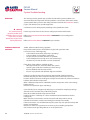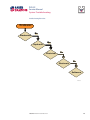
1
PVG 32
Proportional Valves
Service Manual
PVG 32
Service Manual
Revisions
HISTORY OF REVISIONS
Table of Revisions
Date
Page
Changed
Rev.
November 2012
December 2011
October 2010
March 2010
August 2008
41
41
last
last
-
Revised torque on assembly nuts
Revised torque on assembly nuts
new back page
Fix Osaka address
First edition
AE
AD
AC
AB
AA
© 2012 Sauer-Danfoss. All rights reserved.
Sauer-Danfoss accepts no responsibility for possible errors in catalogs, brochures and other printed material.
Sauer-Danfoss reserves the right to alter its products without prior notice. This also applies to products
already ordered provided that such alterations aren’t in conflict with agreed specifications. All trademarks in
this material are properties of their respective owners. Sauer-Danfoss and the Sauer-Danfoss logotype are
trademarks of the Sauer-Danfoss Group.
2
11039167 • Rev AE • November 2012
PVG 32
Service Manual
Contents
INTRODUCTION
Overview............................................................................................................................................................ 5
General instructions....................................................................................................................................... 5
Safety precautions.......................................................................................................................................... 6
Unintended machine movement........................................................................................................ 6
Flammable cleaning solvents................................................................................................................ 6
Fluid under pressure................................................................................................................................. 6
Personal safety............................................................................................................................................ 6
Hazardous material................................................................................................................................... 6
Acronyms........................................................................................................................................................... 7
OPERATION
PVG 32 group with open center PVP (PVB with flow control spool)............................................. 8
PVG 32 group with closed center PVP (PVB with flow control spool).......................................... 8
PVG 32 sectional drawing............................................................................................................................ 9
PVPC plug for external pilot oil supply..................................................................................................10
PVPC with check valve for open center PVP..................................................................................10
PVPC without check valve for open center PVP............................................................................10
Friction detent................................................................................................................................................11
PVMR Friction detent..............................................................................................................................11
PVMF Mechanical float position lock................................................................................................11
PVBS, main spools for flow control (standard)....................................................................................12
PVBS, main spools for flow control (with linear characteristics)...................................................12
PVBS, main spools for pressure control.................................................................................................12
PVPX Electrical LS unloading valve.........................................................................................................13
SYSTEM
TROUBLESHOOTING
Overview..........................................................................................................................................................14
Troubleshooting a PVG valve....................................................................................................................14
No cylinder/motor response in either direction when remote controller is actuated.........16
Cylinder/motor responds in one direction only.................................................................................16
Main valve spool moves without oil passing to cylinder/motor..................................................17
Cylinder/motor operates without remote controller being operated.......................................18
Cylinder/motor responds slowly to remote electrical or hydraulic controller actuation....19
Erratic cylinder/motor response to electrical or hydraulic controller operation....................19
Hydraulic oil supply......................................................................................................................................20
Electrical supply.............................................................................................................................................21
Hydraulic (remote) pilot control pressure............................................................................................21
11039167 • Rev AE • November 2012
3
PVG 32
Service Manual
Contents
PVG 32 COMPONENT
TROUBLESHOOTING
Pressure relief valve......................................................................................................................................22
Pressure reducing pilot valve....................................................................................................................22
Pressure gauge connection.......................................................................................................................24
Open center plug..........................................................................................................................................25
Closed center plug and orifice..................................................................................................................26
Pressure adjustment spool........................................................................................................................27
LS connection.................................................................................................................................................28
LS signal............................................................................................................................................................29
Shuttle valve....................................................................................................................................................30
LS pressure limiting valve...........................................................................................................................31
LS A, B shuttle..................................................................................................................................................32
Main spool.......................................................................................................................................................32
Shock and anti-cavitation valve PVLP....................................................................................................34
Pressure compensator.................................................................................................................................35
Load drop check valve . ..............................................................................................................................36
Maximum oil flow adjustment screws for ports A and B................................................................37
PVM module....................................................................................................................................................38
PVS module.....................................................................................................................................................39
PVPVM module..............................................................................................................................................40
PVAS module...................................................................................................................................................41
PVPX LS unloading valve............................................................................................................................41
PVEH, PVES, PVEA electrical actuators....................................................................................................42
PVEO On/Off electrical actuator..............................................................................................................44
4
11039167 • Rev AE • November 2012
PVG 32
Service Manual
Introduction
OVERVIEW
This manual includes information for servicing PVG 32 valves. It includes a description
of the units and their individual components, troubleshooting information, and minor
repair procedures.
Performing minor repairs may require removal from the vehicle/machine. Thoroughly
clean the unit before beginning maintenance or repair activities. Since dirt and
contamination are the greatest enemies of any type of hydraulic equipment, follow
cleanliness requirements strictly. This is especially important when changing the system
filter and when removing hoses or plumbing.
A worldwide network of Sauer-Danfoss Global Service Partners is available for major
repairs. Sauer-Danfoss trains and certifies Global Service Partners on a regular basis. You
can locate your nearest Global Service Partner using the distributor locator at www.
sauer-danfoss.com.
For specifications and operating parameters on PVG 32 valves, refer to PVG 32 Technical
Information Manual 520L0344.
Do not attempt to service PVG valves without build sheet specifications for reference.
GENERAL INSTRUCTIONS
Follow these general procedures when repairing PVG 32 valves.
wRemove the unit
Chock the wheels on the vehicle or lock the mechanism to inhibit movement. Prior to
performing repairs, remove the unit from the vehicle/machine. Be aware that hydraulic
fluid may be under high pressure and/or hot. Inspect the outside of the valve stack and
fittings for damage. Cap hoses after removal to prevent contamination.
eKeep it clean
Cleanliness is a primary means of assuring satisfactory motor life, on either new or
repaired units. Clean the outside of the valve thoroughly before disassembly. Take care
to avoid contamination of the port connections on the valve stack. Clean parts using a
clean solvent wash and air dry.
As with any precision equipment, keep all parts free of foreign materials and chemicals.
Protect all exposed sealing surfaces and open cavities from damage and foreign material.
If left unattended, cover the valve with a protective layer of plastic.
dReplace all O-rings and gaskets
Sauer-Danfoss recommends you replace all O-rings. Lightly lubricate all O-rings with
clean petroleum jelly prior to assembly.
tSecure the unit
For repair, place the unit in a stable position with the shaft pointing downward. Secure
the motor while removing and torquing controls, and valves.
11039167 • Rev AE • November 2012
5
PVG 32
Service Manual
Introduction
SAFETY PRECAUTIONS
Always consider safety precautions before beginning a service procedure. Protect
yourself and others from injury. Take the following general precautions whenever servicing a
hydraulic system.
Unintended machine movement
W Warning
Unintended movement of the machine or mechanism may cause injury to the technician
or bystanders. To protect against unintended movement, secure the machine or disable/
disconnect the mechanism while servicing.
Flammable cleaning solvents
W Warning
Some cleaning solvents are flammable. To avoid possible fire, do not use cleaning
solvents in an area where a source of ignition may be present.
Fluid under pressure
W Warning
Escaping hydraulic fluid under pressure can have sufficient force to penetrate your skin
causing serious injury and/or infection. This fluid may also be hot enough to cause burns.
Use caution when dealing with hydraulic fluid under pressure. Relieve pressure in the
system before removing hoses, fittings, gauges, or components. Never use your hand
or any other body part to check for leaks in a pressurized line. Seek medical attention
immediately if you are cut by hydraulic fluid.
Personal safety
W Warning
Protect yourself from injury. Use proper safety equipment, including safety glasses, at all
times.
Hazardous material
W Warning
Hydraulic fluid contains hazardous material. Avoid prolonged contact with hydraulic
fluid. Always dispose of used hydraulic fluid according to state and federal environmental
regulations.
6
11039167 • Rev AE • November 2012
PVG 32
Service Manual
Introduction
ACRONYMS
This table provides a definition of commonly used terms.
P = Proportional V = Valve
PVP
Pump side module
PVPV/M
Pump side module
PVB
Basic module
PVLA
Anti-cavitation valve
PVLP
Shock and anti-cavitation valve
PVS/PVSI
End plate
PVAS (PVP, PVPV/M)
Assembly kit for PVP, PVPV/M
PVPX, LS
LS Unloading valve
PVPC
Plug for external pilot oil supply
PVBS
Main spool
PVM
Mechanical activation
PVMD
Cover for mechanical activation
PVH
Cover for hydraulic activation
PVMF
Cover for mechanical float
PVMR
Cover for friction detent PVMR or float position
PVEH, PVES, PVEA
Electrical activation
PVEM
Electrical activation
PVEO
Electrical activation
11039167 • Rev AE • November 2012
7
PVG 32
Service Manual
Operation
PVG 32 GROUP WITH
OPEN CENTER PVP (PVB
WITH FLOW CONTROL
SPOOL)
When the pump starts, and the main spools in the individual basic modules (11) are in
the neutral position, oil flows from the pump, through connection P, across the pressure
adjustment spool (6) to tank. The oil flow led across the pressure adjustment spool
determines the pump pressure (stand-by pressure).
When one or more of the main spools actuate, the highest load pressure is fed through
the shuttle valve circuit (10) to the spring chamber behind the pressure adjustment
spool (6), and completely or partially closes the connection to tank.
Pump applies pressure to the right-hand side of the pressure adjustment spool (6). The
pressure relief valve (1) opens if the load pressure exceeds the set value, diverting pump
flow back to tank.
In a pressure-compensated basic module the compensator (14) maintains a constant
Pressure drop across the main spool—both when the load changes and when a module
with a higher load pressure is actuated.
With a non pressure-compensated basic module incorporating a load drop check valve
(18) in channel P, the check valve prevents return oil flow. The basic module can have the
load drop check valve in channel P for functions with over-center valves.
The shock valves PVLP (13) with fixed setting and the suction valves PVLA (17) on ports
A and B are used for the protection of the individual working function against overload
and/or cavitation.
An adjustable Load Sensing (LS) pressure limiting valve (12) can be built into the A and B
ports of pressure-compensated basic modules to limit the pressure from the individual
working functions.
The LS pressure limiting valves save energy compared to the shock valves PVLP. With
PVLP all the oil flow to the working function flows across the combined shock and
suction valves to tank if the pressure exceeds the fixed setting. With LS pressure limiting
valves, an oil flow of about 2 l/min [0.5 US gal/min] flows across the LS pressure limiting
valve to tank if the pressure exceeds the valve setting.
PVG 32 GROUP WITH
CLOSED CENTER PVP
(PVB WITH FLOW
CONTROL SPOOL)
In the closed center version, an orifice (5) and a plug (7) are fitted instead of the plug (4).
This means that the pressure adjustment spool (6) only opens to tank when the pressure
in channel P exceeds the set value of the pressure relief valve (1).
In LS systems, the load pressure flows to the pump regulator via the LS connection (8).
In the neutral position the pump control sets the displacement so that leakage in the
system is compensated to maintain the set stand-by pressure. When a main spool is
actuated, the pump regulator adjusts the displacement to maintain the set differential
pressure between P and LS.
The pressure relief valve (1) in PVP should be set at a pressure of approximately 30 bar
[435 psi] above maximum system pressure (set on the pump or external pressure relief
valve).
8
11039167 • Rev AE • November 2012
PVG 32
Service Manual
Operation
PVG 32 SECTIONAL
DRAWING
PVP
PVB
PVB
1.
2.
3.
4.
5.
6.
7.
8.
9.
10.
Pressure relief valve
Pressure reduction valve for pilot oil supply
Pressure gauge connection
Plug, open centre
Orifice, closed centre
Pressure adjustment spool
Plug, closed centre
LS connection
LS signal
Shuttle valve
11039167 • Rev AE • November 2012
11.
12.
13.
14.
15.
16.
17.
18.
19.
20.
Main spool
LS pressure limiting valve
Shock and suction valve, PVLP
Pressure compensator
LS connection, port A
LS connection, port B
Suction valve, PVLA
Load drop check valve
Pilot oil supply for PVE
Max. oil flow adjustment screws for
ports A and B
9
PVG 32
Service Manual
Operation
PVPC PLUG FOR
EXTERNAL PILOT OIL
SUPPLY
PVPC with check valve for open center PVP
PVPC, with check valve, is used in systems
where it is necessary to operate the
PVG 32 valve by means of the electrical
remote control without pump flow.
When the external solenoid valve is
opened, oil from the pressure side of the
cylinder is fed via the PVPC through the
pressure reducing valve to act as the
pilot supply for the electrical actuators.
This means that a load can be lowered
by means of the remote control lever
without starting the pump. The built-in
check valve prevents the oil from flowing
via the pressure adjustment spool to
tank.
Oil
Flow
Direction
With the pump functioning normally, the external solenoid valve is closed to ensure that
the load is not lowered due to the pilot supply oil flow requirement of approximately
1 l/min [0.26 US gal/min].
With closed center PVP, the external pilot oil supply can be connected to the pressure
gauge connection without the use of a PVPC plug.
PVPC without check valve for open center PVP
PVPC, without check valve, is used
in systems where it is necessary to
supply the PVG 32 valve with oil from a
manually operated emergency pump
without directing oil flow to the pilot oil
supply (oil consumption about 1 l/min)
Oil
[0.25 US gal/min].
Flow
When the main pump is working
Direction
normally, the oil is directed through
the PVPC plug through the pressure
reduction valve to the electrical
actuators.
When the main pump flow fails, the
external shuttle valve ensures that the
oil flow from the manually operated
emergency pump is used to pilot open
For specifications on PVG 32 valves, refer
the over center valve and lower the load.
to PVG 32 Technical Information Manual
The load can only be lowered using the
520L0344.
mechanical operating lever of the PVG
32 valve.
With closed center PVP, the external pilot oil supply can be connected to the pressure
gauge connection without the use of a PVPC plug.
10
11039167 • Rev AE • November 2012
PVG 32
Service Manual
Operation
FRICTION DETENT
PVMR Friction detent
The friction detent PVMR allows the
directional spool to be held in any
position, resulting in infinitely variable,
pressure compensated flow. The spool
position will be held indefinitely without
the necessity of holding the mechanical
lever.
PVMR should only be used together
with PVB basic modules with pressure
compensator.
PVMF Mechanical float position lock
This allows the float spool to be held in the float position after release of the mechanical
handle.
PVMF
P A F
(Standard assembly)
P B F
(Optional assembly)
11039167 • Rev AE • November 2012
PVMF
P B F
(Standard assembly)
P A F
(Optional assembly)
11
PVG 32
Service Manual
Operation
PVBS, MAIN SPOOLS
FOR FLOW CONTROL
(STANDARD)
When using standard flow control spools, the pump pressure is determined by the
highest load pressure. This is done either via the pressure adjustment spool in open
center PVP (fixed displacement pumps) or via the pump regulator (variable displacement
pumps).
In this way the pump pressure will always correspond to the load pressure plus the
stand-by pressure of the pressure adjustment spool or the pump regulator.
This will normally give optimum and stable adjustment of the oil flow.
PVBS, MAIN SPOOLS
FOR FLOW CONTROL
(WITH LINEAR
CHARACTERISTICS)
PVBS main spools with linear characteristic have less dead band than standard spools
and a completely proportional ratio between control signal and oil flow in the range
beyond the dead band.
W Warning
PVBS with linear characteristic must never be used together with PVEM electrical
actuators.
The interaction between the small dead band of the spools and the hysteresis of the
PVEM actuator of 20% involves a risk of building up a LS pressure in neutral position.
PVBS, MAIN SPOOLS FOR
PRESSURE CONTROL
In a few systems load sensing pump
pressure may result in unstable
adjustment of the oil flow and a
tendency towards system hunting. This
may be the case with working functions
that have a large moment of inertia
or over-center valves. In such systems
main spools for pressure control can be
advantageous. The spools are designed
in such a way that the pump pressure is
controlled by the spool travel. The main
spool must be displaced until the pump
pressure just exceeds the load pressure
before the working function is applied.
If the main spool is held in this position, the pump pressure will remain constant – even if
the load pressure changes – giving a stable system.
The use of pressure control spools, however, also means that:
• the oil flow is load dependent
• the dead band is load dependent
• the pump pressure can exceed the load pressure by more than is usual.
Due to these factors use pressure control spools only when you know for certain that
problems with stability will arise – or already have arisen.
Use LSA/B when pressure stability is an issue.
12
11039167 • Rev AE • November 2012
PVG 32
Service Manual
Operation
PVPX ELECTRICAL LS
UNLOADING VALVE
PVPX is a solenoid LS unloading valve. PVPX is fitted into the pump side module enabling
a connection to be made between the LS and the tank lines. Thus the LS signal can be
relieved to tank by means of an electric signal.
For a PVP pump side module in open center version the relief to tank of the LS signal
means that the pressure in the system is reduced to the sum of the tank port pressure
plus the neutral flow pressure for the pump side module.
For a PVP pump side module in closed center version, relief to tank of the LS signal
occurs when the pressure is reduced by the sum of the tank port pressure for the pump
side module plus the stand-by pressure of the pump.
C Caution
Protect yourself from injury. Use proper safety equipment, including safety glasses, at all
times.
11039167 • Rev AE • November 2012
13
PVG 32
Service Manual
System Troubleshooting
OVERVIEW
W Warning
This troubleshooting
guide for the PVG valve
assemblies does not cover
valves that have been
altered from original valve
build specifications
TROUBLESHOOTING A
PVG VALVE
This section provides general steps to follow if undesirable system conditions are
observed. Follow the steps listed until the problem is solved. Some of the items will be
system specific. Always observe the safety precautions listed in the Introduction section,
page 6, and related to your specific equipment.
Confirm that valve is built properly according to the specification sheet.
If necessary, install a lever to the valve to verify proper mechanical function.
Refer to PVG 32 Technical Information Manual 520L0344 for valve configuration
information.
Refer to PVG 32 Parts Manual 11006794 for part numbers.
THINK - before troubleshooting a problem.
Every fault location process should follow a logical and systematic order.
It is wisest to start at the beginning:
• Is the oil level correct when the pump is operating?
• Is the condition of oil and filters acceptable?
• Are pressure, flow, and flow direction as specified?
• Is the oil temperature too high or too low (oil viscosity)?
• Are there any unusual vibrations or noise (cavitation)?
If the driver of the vehicle is available, ask him:
• What type of fault it is and how it affects the system?
• How long he has felt that something has been wrong?
• If he has “fiddled” with the components?
• If he has any hydraulic and electrical diagrams available?
Diagrams are often found in the instructions included with vehicles/machines.
Unfortunately they are often so technical that they are not of much use in a fault
location situation. However; the diagram usually shows the order of, and the connections
between, the individual components.
When a defective component is identified, clean the component and its surroundings
before removal.
Remove loose paint from pipes and fittings.
Cover all holes, hoses and pipe ends with plugs or seal with, for example, plastic bags
after removal to avoid the entry of dirt during repairs.
Never disassemble hydraulic components outside.
Perform repairs in a workshop on a clean workbench (covered with clean cloth or
newspaper).
Make sure that a Sauer-Danfoss service manual for with the product is handy.
Follow the instructions word for word during disassembly and assembly.
If these instructions are not followed closely the system may not operate correctly after
repairs are completed.
Note that in some cases special tools are necessary for assembling the product.
Our service manuals give full guidance on use of special tools.
14
11039167 • Rev AE • November 2012
PVG 32
Service Manual
System Troubleshooting
Troubleshooting flow chart
Problem?
Mechanical
Mechanical
No
No
No
No
Hydraulic
Hydraulic
Electrical
Electrical
No
No
Electronic
Electronic
No
No
Software
P107 823
11039167 • Rev AE • November 2012
15
PVG 32
Service Manual
System Troubleshooting
NO CYLINDER/MOTOR RESPONSE IN EITHER DIRECTION WHEN REMOTE CONTROLLER IS ACTUATED
Cause
Verify if fault is mechanical,
electrical or hydraulic
Sticking main spool
Check
Corrective action
Operate manual lever to confirm mechanical or
electrical or hydraulic
If moving the manual lever operates the cylinder/
motor check electrical or hydraulic
Remove manual, electrical, and hydraulic
actuators from the valve section. Remove main
spool from valve section and inspected for
damage. If no damage reinstall the main valve
spool and it should move freely in the valve
section bore.
Replace the valve module and main spool. If any
damage is found on the main spool
Check movement of manual lever when
electrical controller is operated
If manual lever does not move check electrical
voltage signal from controller, wiring at the PVE
module
Internal filters blocked
Check movement of manual lever when
hydraulic controller is operated
If manual lever does not move check hydraulic
controller pressure at the PVG valve module - 25 Bar
[360 PSI]
If none of the above check pump per
manufacturers recommended procedure
Repair or replace pump per manufacturers
recommended procedure
Check for blockage in internal filters
Remove blockage
CYLINDER/MOTOR RESPONDS IN ONE DIRECTION ONLY
Cause
Check
Corrective action
Operate manual lever in both directions to
confirm if mechanical or electrical or hydraulic
If moving the manual lever operates the cylinder/
motor in both directions check electrical or
hydraulic
If operating the manual lever strokes the
cylinder/motor in one direction only, check
manual stop screw adjustment
Back out manual stop on manual controller and
torque the jam not to 8 Nm [70 lbf•in] Do not
exceed maximum torque
Check movement of manual lever when
electrical controller is operated
If manual lever does not move in one direction
check electrical signal from controller and wiring at
the PVE module
Check movement of manual lever when
hydraulic controller is operated
If manual lever does not move in both directions
check hydraulic pressure at the PVG module
Air in system
Entrained air generates heat under pressure
Look for foam or bubbles in reservoir. Check for
leaks on inlet side of charge pump.
Internal leakage
Excessive internal leakage may overheat the
system.
Install loop flushing defeat option and monitor case
flow. If case flow is excessive, motor may require
major repair. Contact Sauer-Danfoss Service.
Shock valves
Swap and see if problem follows
Replace valves
Solenoid actuation
If power is OK from controller
Repair wiring to PVE module
Main spool travel restricted
Stop on manual controller turned in too far
Back out manual stop on manual controller
Remote electrical controller
Insufficient signal from electrical controller
Repair or replace electrical controller
PVEO connections
Incorrect PVE/PVEO connections
Connect correct way
Remote hydraulic controller
PVRH
Insufficient pilot oil pressure from remote
hydraulic controller Pressure needs to be 25 Bar
[360 psi]
Repair or replace remote hydraulic controller
Verify if fault is mechanical,
electrical or hydraulic
16
11039167 • Rev AE • November 2012
PVG 32
Service Manual
System Troubleshooting
MAIN VALVE SPOOL MOVES WITHOUT OIL PASSING TO CYLINDER/MOTOR
Cause
Check
Corrective action
Insufficient oil supply to valve
Check the pump per manufacturers procedure
Repair or replace pump per manufacturers procedure
Optional pressure compensator in
valve section not functioning
Check compensator spool
Replace spool
Insufficient load pressure at
compensator spring chamber
LS drilling holes plugged
Clean or replace
Cylinder/motor load too high for
pressure setting of the system
Check pressure at the valve
If pressure is set to spec. per valve lower load on
cylinder/motor
Blocked LS galleries
Inspect for blockage in LS galleries
Remove blockage in LS galleries
Shuttle valve faulty
Inspect shuttle valve
Repair or replace
Blocked LS lines to pump controller
Inspect LS lines from PCG to pump controller
Remove blockage in LS lines from the PVG valve to
pump controller
Oil bypassing at shock valve/anticavitation check valve
Check if stuck open or damaged
Replace valve
Internal leakage in cylinder/motor
Inspect for by-passing of oil per cylinder/motor
manufacture per manufactures procedure
Repair or replace cylinder/motor per manufactures
procedure
Too much leakage in LS spool in
pump control
Check bleed orifice in LS control
Use a LS pump control with no bleed orifice
Blocked thermal orifice
check thermal orifice (blocked)
Replace thermal orifice
Load too high for system
Check for proper system pressure
Adjust pressure to valve specification
Internal leakage in cylinder/motor
Inspect for bypassing of oil per cylinder/motor
manufacturer specification
Repair or replace cylinder/motor
Shock valve or anti-cavitation check
valve faulty
Inspect for damage and contamination
Repair or replace cylinder/motor
System relief valve pressure set too
low for load
Install pressure gauge and check pressure
Adjust pressure to system specification
Lower load
Cylinder/motor load too high for
pressure settings of system
Check load pressure at PVB-LS port
Reduce load pressure if exceeds maximum pressure
limit of the system
Maximum system pressure should be approx. 25
Bar [365 PSI] above highest load pressure
Adjust maximum system pressure if necessary
Adjust pump pressure compensator setting if
necessary
11039167 • Rev AE • November 2012
17
PVG 32
Service Manual
System Troubleshooting
CYLINDER/MOTOR OPERATES WITHOUT REMOTE CONTROLLER BEING OPERATED
Cause
Check
Corrective action
Spool control tension rod loose
Confirm torque on spool control tension rod
Torque to 8 Nm [70 lbf•in]
Electrical feedback transducer not in
neutral position
Check the feedback pin in the PVE. It should be
loose
Replace transducer
Remote electrical controller neutral
position switch faulty
Disconnect the connection at the PVE. It should
come back to neutral
Repair or replace faulty switch or wiring at remote
controller
Sticking pressure control valve in
remote hydraulic controller
Disconnect the hydraulic signal line from valve
Repair or replace faulty remote hydraulic controller
Sticking main spool in valve section
Remove manual, electrical, and hydraulic
actuators from the valve section. Remove main
spool from valve section and inspected for
damage. If no damage reinstall the main valve
spool. Spool should move freely in the valve
section bore.
Replace the valve module and main spool if any
damage is found on the main spool
Internal fault in the PVE/PVEH/PVEM/ PVEO check continuity. All other PVE, check LED
PVEO
(Red means internal error)
Replace faulty PVE/PVEH/PVEM/PVEO
Contamination in the hydraulic oil
Flush hydraulic system. Fill with clean filtered oil.
18
Take oil samples to confirm
11039167 • Rev AE • November 2012
PVG 32
Service Manual
System Troubleshooting
CYLINDER/MOTOR RESPONDS SLOWLY TO REMOTE ELECTRICAL OR HYDRAULIC CONTROLLER ACTUATION
Cause
Check
Corrective action
Insufficient system pressure
Install pressure gauge and record pressure
If pressure is low adjust pressure setting to valve
specification or pump manufacturers specification
Main spool travel limited
Check stops on manual lever controller end
for proper adjustment. Refer to Component
troubleshooting section, page 22.
Adjust the manual lever stops and torque the jam
nuts to 8 Nm [70 lbf•in] Do not exceed maximum
torque
Incorrect signal voltage from
electrical controller
Check the signal voltage from the controller with
a volt meter
If signal voltage is incorrect repair or replace
electrical controller
Incorrect hydraulic pressure
signal from remote hydraulic
controller
Check pressure from the remote hydraulic
controller - 25 Bar [360 PSI]
If pressure is too low, repair or replace remote
hydraulic controller per manufacturers instructions.
Insufficient pilot oil - all sections
Check pilot for contamination and correctly
assembled parts - 10-15 bar [145-218 psi] Electric
- 25 bar [360 psi] Hydraulic
Replace inlet module NOTE: Check with S-D TST
Insufficient LS pump stand by
pressure
Check pilot PSI - 10-15 bar [145-218 psi] Electric 25 bar [360 psi] Hydraulic
Adjust or replace pump
Flow is not load independent
PVLP check for cracks
Check LS pressure vs load pressure
Replace valve
ERRATIC CYLINDER/MOTOR RESPONSE TO ELECTRICAL OR HYDRAULIC CONTROLLER OPERATION
Cause
Check
Corrective action
Electrical actuator faulty
Check signal from controller to PVE
Repair or replace PVE
Main spool centering spring
damaged
Check tension rod for correct torque or damage
Torque to 8 Nm [70 lbf•in] or replace
Main spool position feedback
transducer signal incorrect
Check feedback pin for damage
Replace PVE
Contamination in hydraulic oil
Take oil sample
Flush complete system.
Fill reservoir with clean filtered fluid per OEM
specification
Air in hydraulic pilot lines
Check for air trapped in signal lines from the
controller to the valve section module
Bleed air from the hose connection at the valve
section
Hydraulic remote actuator faulty
Check signal pressure from the remote hydraulic
controller
Repair or replace cylinder/motor
Low hydraulic oil supply
Check fluid level in reservoir
Fill reservoir with clean filtered fluid per OEM
specification
11039167 • Rev AE • November 2012
19
PVG 32
Service Manual
System Troubleshooting
HYDRAULIC OIL SUPPLY
Cause
Pump not running
Check
Corrective action
Check prime mover for operation
Repair or replace prime mover
Check condition of drive coupling
Repair or replace drive coupling
Insufficient oil in reservoir
Check fluid level in reservoir
Fill with clean filtered oil
Leaking or burst supply hose
Inspect lines to valve stack
Repair or replace damaged hose
Relief valve malfunction
Check for contamination and operation of relief
valve
Repair or replace relief valve
Isolating valves are closed
Check that all isolating valves are open and clear
Faulty pump control
Check pump compensator for correct operation
and setting per pump manufacturers
Repair or replace pump compensator per pump
manufacturers recommendations
Low standby pressure in PVP open center pump
Check idle standby pressure - 10 Bar [145 PSI]
Replace
Check condition of compensator spool spring
Replace module due to worn components
Low standby pressure in pump
control - variable pump
Check pump LS control for operation and setting
Stand by pressure should be 15 bar [220 psi]
minimum
Repair or replace LS control per pump
manufacturers procedures
PVP pressure relief valve faulty
Check pressure relief valve spool and spring for
freedom of operation
Replace
PVP orifices blocked
Check PVP orifices for blockage
Remove blockage
Internal filters blocked
Check for blockage in internal filters
Remove blockage
Supply lines blocked
Inspect supply lines for blockages
Remove blockage
Internal hydraulic pilot pressure
insufficient
Inspect pilot oil pressure reducing valve for
proper operation
Repair or replace
Blocked LS galleries
Check LS galleries for blockage
Clean blockage from LS galleries
Shuttle valves faulty
Check LS system shuttle valves for wear and
damage
Replace as needed
Check for contamination per specification HPP 030. Refer to Design Guideline for Hydraulic Fluid Cleanliness, Technical
Information Manual 520L0467. If fluid is out of spec., flush hydraulic system and fill with clean filtered oil.
20
11039167 • Rev AE • November 2012
PVG 32
Service Manual
System Troubleshooting
ELECTRICAL SUPPLY
Cause
No electrical power
Check
Corrective action
Check electrical circuit
Repair as needed
Verify emergency stop switch is in the proper operating
position
Reset
Neutral position switch faulty
Check operation of neutral position switch in remote controller
(if connected in circuit) PVRE/PVRES/PVREL
Replace switch
Incorrect signal voltage
Check voltage levels at solenoid plug
Proportional operation - Refer to page 43
Udc: Supply voltage (100%)
Us: Supply signal voltage (25-50-75%)
Ground: Live or ground connection
On-Off Operation
Udc: Supply voltage if selected
Us: Supply voltage if selected
Ground: Live or ground connection
Solenoid valve faulty PVHC
Check coil resistance
Check data for resistance
Insufficient pilot supply
Check pilot pressure - 10-15 bar [145-218 psi]/PVHC 25 bar [360
psi]
Replace
Main spool position feedback
transducer signal incorrect
Test oil for contamination and or water content
If oil contamination is too high, flush
hydraulic system or replace oil if necessary.
If problem persists change PVE
Incorrect PVE connections
Check that the proportional remote electrical controller has not
been connected to an ON-OFF PVEO solenoid
Connect wires correctly
HYDRAULIC (REMOTE) PILOT CONTROL PRESSURE
Cause
Insufficient pilot pressure
Check
Corrective action
Check pilot oil pressure 5-15 bar [72-220 psi] delta between A
and B port on remote
PVG32: 5-15 Bar [72-217 PSI]
Insufficient pilot oil supply
Check pilot oil flow rate is adequate
Pilot flow should be 1.0 L/min [0.264 GPM] per section
Check pilot lines for blockage
Remove blockage
Air in pilot line
Check for trapped air in pilot lines
Bleed air from pilot lines at PVH
Pilot lines incorrectly sized
Check pressure drop
Check and reduce length or pilot lines
Increase diameter of pilot lines
Use steel tube for long pilot line runs
Hydraulic remote pilot operator
faulty
Check operation of hydraulic remote pilot controller
Repair or replace
Check supply pressure to hydraulic remote controller minimum 25 bar [360 psi]
Repair or replace
Check and inspect movement of pressure control valve in
hydraulic controller
Repair per manufacturers procedure, or
replace
Check operation of remote hydraulic controller
Clean and/or repair as necessary
11039167 • Rev AE • November 2012
21
PVG 32
Service Manual
PVG 32 Component Troubleshooting
PRESSURE RELIEF VALVE
Description: Adjustable relief valve. Adjustment range 50 Bar [700 PSI] to 350 Bar [5000
PSI].
Location: The relief is in all PVP Inlet modules
Function: Provides maximum pressure setting above pump pressure setting 30 Bar [450
PSI] Delta for open center and closed inlet sections
Failure mode
Cause
Corrective action
Will not build pressure
Contamination
While under pressure, back out to minimum pressure and allow
oil to leak by for approx. 5 seconds and then readjust to correct
pressure - Replace valve
External leaking
Damaged seat and poppet
Replace complete assembly
Pressure setting is wrong
Pressure adjustment backs off (on open
center application)
Adjust to model code specification
Instability when PC and inlet
relief has too low of a delta
between them
PC at pump should be set 20 bar below
relief valve
Adjust to model code specification
Serviceability: Non serviceable.
Valve removal tool P/N: 155L6485. Torque to 20 Nm [180 lbf•in].
PRESSURE REDUCING
PILOT VALVE
Description: Pressure reducing valve at fixed pressure.
Location: The pressure reducing valve is a option in some PVP Inlet modules.
Function: Provides 10-15 bar [145-218 psi] internal pressure for electrical (PVE) actuators or
provide 25 Bar (360 PSI) (PVHC) and supply for external remote hydraulic actuators (HRC).
These pressures are only present when the load pressures are high enough to satisfy
the required regulated pressure. The open center system at low pump flow may only
develop 9 Bar (130 PSI)
22
11039167 • Rev AE • November 2012
PVG 32
Service Manual
PVG 32 Component Troubleshooting
PRESSURE REDUCING PILOT VALVE (CONTINUED)
Failure mode
Main spools are slow, driven by
PVE 13 Bar [190 PSI] pilot system
Main spools will not move
mechanically or electrical
PVHC 25 bar [360 psi] pilot
system - main spools are slow
Cause
Corrective action
Contamination
Disassemble and clean
Pump pressure too low - below 9 Bar [130
PSI]
Closed center: System increase stand-by to 13 Bar [190 PSI]
Open center: Check gear per pump manufacture procedure
Check system for other components before valve inlet that may
provide a path tank
High tank port pressure. Do not exceed
40 Bar [580 PSI] tank pressure (For PVPs
without T0 option)
Clear restrictions in return system.
Oil viscosity 460 mm2/S [2128 SUS] too high
(cold oil or incorrect viscosity oil)
Warm up system or replace oil with correct viscosity
For T0 option only not being connected to
tank or restricted to tank
Connect T0 (PVP) port option to tank or remove restriction
Internal pressure reducing valve parts
misassembled
Reassemble the internal pressure reducing valve parts correctly
Contamination
Disassemble and clean
Pump pressure too low - below 20 Bar [290
PSI]
Closed center: System increase stand-by to 20 Bar [290 PSI]
Open center: Check gear per pump manufacturers procedure
Check system for other components before valve inlet that may
provide a path tank
High tank port pressure. Tank pressure
should not exceed 40 Bar [580 PSI] (For
PVPs without T0 option)
Check for restrictions in return system and remove
Oil viscosity - 460 mm2/S [2128 SUS] too
high (cold oil or incorrect viscosity oil)
Warm up system or replace oil with correct viscosity
Serviceability: All internal components
can be removed from the cavity, cleaned,
inspected and reassembled back into the
valve
1. Use a 6 mm internal hex wrench to
remove the plug, and then remove
all the other internal components in
the cavity
Pressure reducing pilot valve
Plug
6 mm
25 Nm
[220 lbf•in]
O-ring
Spool
2. Clean all components with clean
solvent
Cone
3. Replace any damaged components.
Lubricate with clean hydraulic oil
4. Correctly reassemble the
components back into the cavity and
torque the plug to 25 Nm [221 lbf•in]
(use an M5 screw to install spool).
11039167 • Rev AE • November 2012
Spring
P107 733E
23
PVG 32
Service Manual
PVG 32 Component Troubleshooting
PRESSURE GAUGE
CONNECTION
Description: Port to install a pressure gauge to check pressure relief valve setting to
valve specification.
Location: On inlet cover to valve stack.
1. Use a 6 mm internal hex to remove and install plug.
2. Torque plug to 35 Nm [308 lbf•in].
Failure mode
Leaking
Cause
Corrective action
Bad seal
Replace with new seal (same type as original seal)
Pressure gauge port
Pressure gauge port
P107 735E
When valve is equipped with the PVPC option use a running tee to measure pressure.
Torque tee to hose adaptor torque specification.
PVPC with check valve
Tee into pressure port
to measure pressure
PVPC with check valve
P107 734E
24
11039167 • Rev AE • November 2012
PVG 32
Service Manual
PVG 32 Component Troubleshooting
OPEN CENTER PLUG
Description: Plug that is installed in the inlet cover for a system with a fixed
displacement pump.
Location: In the PVP module (Inlet cover).
Function: Connection for the load sense signal to shift the unloading spool to build
main system pressure and provides a connection to the main system relief valve.
Failure mode
Valve operates at system relief
setting at all times
Cause
Corrective action
Open center plug is not seated properly
Reinstall plug and torque to 4 Nm [35 lbf•in] using a 3 mm
internal hex wrench
Serviceability: Open center plug is serviceable.
1. Use a 6 mm internal hex to remove cavity plug from valve.
2. Use a 3 mm internal hex to remove open center plug.
3. Clean or replace open center plug.
4. Install open center plug.
5. Torque plug to 4 Nm [35 lbf•in].
6. Install new seal washer and install cavity plug. Torque to 35 Nm [130 lbf•in].
Open center plug
Plug
6 mm
35 Nm
[308 lbf•in]
Seal
washer
Open
center
plug
3 mm
4 Nm
[35 lbf•in]
P107 736E
11039167 • Rev AE • November 2012
25
PVG 32
Service Manual
PVG 32 Component Troubleshooting
CLOSED CENTER PLUG
AND ORIFICE
Description: Plug that is installed in the inlet cover for a system with a variable
displacement pump.
Location: In the PVP module (Inlet cover).
Function: Allow connection for the load sense signal to the pump and provide
connection to the main system relief valve.
Failure mode
Cause
Corrective action
Valve operates at system relief
setting at all times
Plug and orifice are not seated properly
Reinstall orifice and torque to 4 Nm [35 lbf•ft] using a 3 mm
internal hex wrench.
Reinstall plug and torque to 8 Nm [71 lbf•in] using a 8 mm
internal hex wrench
Can not adjust main relief above
pump pressure setting of 30 Bar
[450 psi] Delta for closed inlet
sections
Orifice is plugged
Remove and clean orifice. Reinstall
Serviceability: Closed center plug and orifice are serviceable.
1. Use a 6 mm internal hex to remove cavity plug from valve.
2. Use a 4 mm internal hex to remove closed center plug.
3. Use a 2.5 mm internal hex to remove orifice.
4. Clean or replace orifice. Install orifice. Torque to 4 Nm [35 lbf•in].
5. Install new seal and install closed center plug. Torque to 8 Nm [71 lbf•in].
6. Install new O-ring and install plug. Torque to 35 Nm [130 lbf•in].
Closed center plug
Plug
6 mm
35 Nm [308 lbf•in]
O-ring
Seal
Closed center
plug
4 mm
8 Nm
[70 lbf•in]
Orifice
2.5 mm
4 Nm
[35 lbf•in]
P107 737E
26
11039167 • Rev AE • November 2012
PVG 32
Service Manual
PVG 32 Component Troubleshooting
PRESSURE ADJUSTMENT
SPOOL
Description: Main pump flow unloading spool.
Location: PVP (inlet) module.
Function: For open center systems it is the main relief and unloading spool
For closed center systems it is the main relief spool.
Failure mode
Cause
Corrective action
In open center systems the valve
sections are unstable
High wear allows leakage to tank
Replace compete module
The adjusted pressure will not
Low viscosity oil allowing high leakage
Remove and clean orifice. Reinstall
remain static in a closed center
system
around spool to tank.
High wear
Replace compete module
Serviceability: Spool is not serviceable. Replace complete module.
Pressure adjustment spool
Pressure adjustment spool
Orifice
Plug
P107 739E
11039167 • Rev AE • November 2012
27
PVG 32
Service Manual
PVG 32 Component Troubleshooting
LS CONNECTION
Description: Port for LS signal for LS (static) option only controller for variable flow
pump.
Location: PVP (inlet) module.
Function: Provide a signal to the variable pump controller to create a pressure
differential to have the pump come on stroke for a closed center system.
Failure mode
In closed center systems the
valve sections are unstable
Cause
Insufficient LS flow to satisfy pump
controller
Corrective action
Ensure that the LS controller on the pump does not have
excessive internal leakage - 0.4 l/min [0.106 gal/min]. Repair or
replace the variable pump controller per pump manufactures
specifications
If there is more than one valve in the system ensure that the LS
shuttles are all working properly
Valve operation is slow to
respond or does not respond
Excessive air entrained in the hydraulic oil
Ensure that the oil has enough dwell time in tank, has
good anti-foaming agent, and pump inlet vacuum is within
manufacturers specifications
Air trapped in LS line
Bleed air for LS line at highest point
Insufficient LS flow to satisfy pump
controller
If more than one section, ensure that the LS controller on the
pump does not have excessive internal leakage. Repair or
replace the variable pump controller per pump manufactures
specifications
Excessive air entrained in the hydraulic oil
Ensure that the oil has enough dwell time in tank, has
good anti-foaming agent, and pump inlet vacuum is within
specifications
Air trapped in LS line
Bleed air for LS line at highest point
PVG valve is mounted above hydraulic oil reservoir when shut down and sits idle for some time, the valve could be
voided of oil and this would cause the valve to operate erratically and be slow to respond.
Serviceability: Port is serviceable. Need to connect hose to LS port on pump.
LS connection plug
LS Plug
6 mm
35 Nm [308 lbf•in]
P107 740E
28
11039167 • Rev AE • November 2012
PVG 32
Service Manual
PVG 32 Component Troubleshooting
LS SIGNAL
Description: The PVG32 uses an internal LS signal network for both Open Center and
Closed Center systems. In Open Center systems the internal LS signal network provides
a resolved load sense signal to the pressure adjustment spool controlling the proper
amount of flow and pressure to the operating valve sections. In Closed Center systems
the internal LS signal network provides a resolved load sense signal directly to the LS
pump control which in turn provides the proper amount of flow and pressure to the
operating valve sections.
Location: PVP/PVB Modules.
Function: Directs the highest load pressure to either OC or CC pump control to satisfy
the operating valve section.
Failure mode
Cause
No pump pressure developed in
one or more valve sections
LS passages blocked or restricted
Corrective action
Disassemble valve. Inspect passages for blockage
Serviceability: Not serviceable. Ensure entire system is clean.
LS circuit
PVP
PVB
PVB
LS
circuit
10. Shuttle valve
P107 815E
11039167 • Rev AE • November 2012
29
PVG 32
Service Manual
PVG 32 Component Troubleshooting
SHUTTLE VALVE
Description: Self cleaning internal shuttle system.
Location: PVB (valve section) module.
Function: Determines which valve section is developing highest load pressure.
Failure mode
Valve sections will not build
pressure (NOTE: Normally it
will be one section, but not all
sections)
Cause
Corrective action
Worn shuttle disc
Replace complete module (seat is pressed into module)
Excessive air entrained in the hydraulic oil
Ensure that the oil has enough dwell time in tank, has
good anti-foaming agent, and pump inlet vacuum is within
specifications
Serviceability: Not serviceable. Ensure entire system is clean.
Shuttle valve
Ball should move
freely behind disk.
Exploded view shows internal parts.
Do not disassemble valve.
Ball should move
freely behind disk.
P107 804
30
11039167 • Rev AE • November 2012
PVG 32
Service Manual
PVG 32 Component Troubleshooting
LS PRESSURE LIMITING
VALVE
Description: Optional adjustable pilot relief valve.
Location: PVB (spool body section) module.
Function: Controls the maximum working pressure delivered to each work port.
There is one LS pressure limiting valve for each work port.
Failure mode
Cause
Corrective action
Section will not build pressure in
one spool direction
Contamination
While under pressure back out to minimum pressure and allow
oil to leak by for approx. 5 seconds and then readjust to correct
pressure - Ensure system is clean - Replace PVB
External leaking
Low cartridge torque
Torque to 20 Nm [177 lbf•in] maximum
Replace complete assembly
Pressure adjustment backs off
Adjust pressure to valve specifications
If adjustment doesn’t hold, replace valve
Serviceability: Adjustable and non-serviceable. If adjustment does not solve the
problem, replace complete cartridge.
Valve removal tool P/N: 155L6485. Torque to 20 Nm [177 lbf•in].
11039167 • Rev AE • November 2012
31
PVG 32
Service Manual
PVG 32 Component Troubleshooting
LS A, B SHUTTLE
Description: The shuttle valve isolates the LS(A) and LS(B) load sense signal.
Location: Option PVB module with only load sense relief.
Function: Ensure that each pressure limiter valve can create separate pressures for A and
B LS signal.
Failure mode
Will not build pressure in A or B
work port
Cause
Contamination preventing shuttle ball from
building load sense relief pressure
Corrective action
Replace complete PVB module
LS A, B shuttle
Shuttle
ball
P107 821
MAIN SPOOL
Description: Main directional control.
Location: PVB (valve section) module.
Function: Controls oil flow from pump to work ports A or B.
Failure mode
Cause
Corrective action
Section will not build pressure in
one spool direction
Load sense passages in spool are blocked
Flush out load sense passages in the spool. Spool will need
to be removed to clean
Main valve spool stuck in valve
body (if being used with electrical
actuator)
Refer to Pressure reducing valve section,
page 22
Replace PVM and PVE. Be sure that pilot valve is assembled
correctly.
Mechanical actuator main valve
spool stuck in valve body
Hard particle binding spool in bore
Look down into the A and B work ports to see if the particle
can be removed while the spool is in the valve body. Replace
valve section.
NOTE: Valve body and spool will need to be replaced per
valve specifications
Main spool stuck in valve body
Tie rod over torqued
Replace tie rod kit which includes section seals and torque to
28 Nm [248 lbf•in]
Valve stack mounting surface is not flat
causing a bind on the valve stack
Ensure the mounting surface is flat*
* Flatness in millimeters - T= 0.35 mm X number of PVB modules + 1
32
11039167 • Rev AE • November 2012
PVG 32
Service Manual
PVG 32 Component Troubleshooting
MAIN SPOOL
(CONTINUED)
Serviceability: Main spool is serviceable depending on failure mode.
1. Remove manual actuator using a 5 mm internal hex wrench to remove the 4
mounting screws.
CAREFULLY place the main spool in to an appropriate fixture or vice with card board,
rubber hose or heavy shop towels on the jaws and tighten just enough to keep the spool
from turning in the vice. DO NOT over tighten the main spool in the vice as it will be
distorted and or scratched on sealing lands and the spool will need to be replaced.
2. Remove the tension rod end using a 13 mm open end wrench.
3. Remove the plug at the other end using an 11 mm, or if it has a detent option, use a
12 mm open end wrench.
3. Flush out openings into the main spool cavity at each end.
4. Install plug with a 11 mm or 12 mm open end wrench. Torque to 8 Nm [70 lbf•in].
5. Install centering spring and tension rod using a 13 mm open end wrench and torque
to 8 Nm [70 lbf•in].
6. Carefully reinstall the main valve spool into the valve housing. Do not force the
main spool back into the housing as you will damage the sealing lands in the valve
housing. The spool should move freely in the main spool bore when fully installed.
7. Install a manual actuator. Reassemble in reverse order and torque the 4 mounting
screws to 8 Nm [70 lbf•in]
If section does not build pressure in one direction, wrong spool may have been installed
in valve.
Main spool
Screw
11 mm
8 Nm
[70 lbf•in]
Clean holes
P107 805E
11039167 • Rev AE • November 2012
33
PVG 32
Service Manual
PVG 32 Component Troubleshooting
SHOCK AND
ANTI-CAVITATION
VALVE PVLP
Description: Optional work ports non adjustable pressure relief valve.
Location: PVB (valve section) Module.
Function: Removes any transient pressure spikes generated by the load.
The shock valves PVLP with fixed setting and the anti-cavitation valves PVLA on ports A
and B are used for the protection of the individual work function against overload and/
or cavitation.
There is one shock valve for each work port.
Failure mode
Will not build pressure in A or
B port
Cause
Valve may be damaged and not able to seal
Corrective action
Replace with correct part number per valve specification
Serviceability: This valve may be disassembled and cleaned, however, internal parts are
not available separately. If you suspect valve malfunction, replace with a new valve and
test system operation.
PVLP valve
Plug
13 mm
36 Nm
[310 lbf•in]
Do not try to adjust
or disassemble PVLP
P107 743E
34
11039167 • Rev AE • November 2012
PVG 32
Service Manual
PVG 32 Component Troubleshooting
PRESSURE
COMPENSATOR
Description: Optional pressure compensator maintains a constant pressure drop across
the main spool.
Location: PVB (Valve section) Module.
Function: In a pressure-compensated basic module the compensator maintains a
constant pressure drop across the main spool – both when the load changes and when a
module with a higher load pressure is actuated.
Failure mode
Cause
Corrective action
Valve section unstable flow
High wear allows leakage
Replace complete module
LS pressure limiting valve pressure
adjustment will not remain static
High wear
Replace complete module
Serviceability: Pressure compensator is not serviceable. If you suspect valve
malfunction, replace complete module.
Pressure compensator valve
P107 744E
Pressure compensator spool
Pressure compensator spool
P107 822
11039167 • Rev AE • November 2012
35
PVG 32
Service Manual
PVG 32 Component Troubleshooting
LOAD DROP CHECK
VALVE
Description: Keeps the load from dropping when transitioning from spool neutral to
lifting the load.
Location: PVB (valve section) module.
Function: Optional drop check to keep the load from dropping. Prevents high
pressure functions from supplying low pressure functions when both are actuated
simultaneously.
Failure mode
Load drops excessively when
trying to lift load
Cause
Corrective action
Worn parts.
Replace complete PVB module
Hard particle in seat area does not allow the
Replace complete module
seat to seal
Serviceability: Load drop check valve is not serviceable. If you suspect valve
malfunction, replace complete module.
Load drop check valve
Load drop check valve
P107 747E
Load drop check valve
P107 748E
36
11039167 • Rev AE • November 2012
PVG 32
Service Manual
PVG 32 Component Troubleshooting
MAXIMUM OIL FLOW
ADJUSTMENT SCREWS
FOR PORTS A AND B
Description: Optional mechanical flow limiter.
Location: PVM manual control handle.
Function: Determines the stroke of the main spool in the PVB.
Failure mode
Cause
Corrective action
Cylinder/motor functions too
slow or too fast
Mechanical stop screws out of adjustment
per valve spec.
Use a 8mm open end wrench to loosen the jam nut and then
3mm internal hex wrench to adjust the mechanical adjusting
screw CCW to increase speed. After adjusting hold the adjusting
screw and torque the jam nut to 8 Nm [70 lbf•in] maximum
Leaking past adjusting screws
Check torque on seal nut 8 Nm [71 lbf•in]
Retorque or replace seal nuts
C Caution
When adjusting main spool flow ensure that electrical or hydraulic actuators are not
active at the time, if so equipped.
Adjusting screws for ports A and B
For standard mount, top adjusting screw is B
and bottom adjusting screw is A
P107 816E
11039167 • Rev AE • November 2012
37
PVG 32
Service Manual
PVG 32 Component Troubleshooting
PVM MODULE
Description: Manual control lever.
Location: Mounted on either end of the PVB main spool.
Function: Manual override capable of limiting the stroke of the main spool, and is used
to center the spool in neutral.
Failure mode
Cause
Corrective action
Leaking externally between PVM
and PVB
Back pressure is exceeding 40 Bar [580 PSI]
on tank line
Replace PVM module, seals, and lower tank port pressure
T0 port not connected to tank or restricted
Connect to tank, remove restriction, and remove blockage
or blocked
PVM module
O-rings
Seal
Screw (x4)
5 mm
8 Nm [70 lbf•in]
P197 806E
38
11039167 • Rev AE • November 2012
PVG 32
Service Manual
PVG 32 Component Troubleshooting
PVS MODULE
Description: End cover.
Location: Mounted on the last PVB of the valve stack.
Function: Serves as blanking cover and drain for LS circuit.
Failure mode
Cause
Leaking externally between PVS
and PVB
Back pressure is exceeding 40 Bar [580 PSI]
on tank line
Replace PVS module, seals, and lower tank line pressure
Corrective action
Maximum pressure:
Aluminum - 300 bar [4500 psi]
Steel - 350 bar [5000 psi]
Reduce system pressure
PVS plugs
P107 707E
For specifications and operating parameters on PVG 32 valves, refer to PVG 32 Technical
Information Manual 520L0344.
11039167 • Rev AE • November 2012
39
PVG 32
Service Manual
PVG 32 Component Troubleshooting
PVPVM MODULE
Description: Mid-inlet module only for closed center systems.
Location: Mounted between multiple PVB’s in a valve stack.
Function: Provides pressure and tank connections to the valve stack allowing increased
flow.
Failure mode
Leaking externally between
PVPVM and PVB
Cause
Corrective action
Uneven mounting surface and mounting
screw torque
Ensure the valve stack is mounted on a even surface and torque
down correctly
Tie rods torqued too tight
Replace tie rod kit which include section seals and torque to 28
Nm [248 lbf•in]
Valve stack can not build
pressure per valve spec.
Flow exceeding 61 gpm
Lower flow to 61 gpm, and replace the tie rod kit and seals
Option PVLP (shock valve) not seating
correctly in cavity caused by valve not
being installed correctly or it has failed
Install components correctly or replaced damaged components
* Flatness in millimeters - T= 0.35 mm X number of PVB modules + 1
PVPVM module
Do not try to adjust
or disassenmble PVLP
13 mm
40 Nm
[354 lbf•in]
Plug
40
11039167 • Rev AE • November 2012
P107 808E
PVG 32
Service Manual
PVG 32 Component Troubleshooting
PVAS MODULE
Description: Tie rod kit.
Location: Through the valve stack.
Function: Holds the stack together.
Failure mode
Leaking externally between
sections
Cause
Corrective action
Tie rods under torqued
Check and retorque - 28 Nm [248 lbf•in]
Tie rods torque too tight
Replace and retorque - 28 Nm [248 lbf•in]
If replacing seal kit,
replace tie rods also
8-
248 -
PVPX LS UNLOADING
VALVE
(REFER TO PAGE 13 FOR
VALVE OPERATION)
P107 817E
Description: Optional two way two position solenoid.
Location: In the PVP.
Function: A safety device that dumps load sense to tank to prevent the pump from
building pressure.
Failure mode
Manual override leaking
externally
Solenoid will not shift
Cause
Corrective action
Not torqued correctly
Check and retorque to 45 Nm [400 lbf•in]
High usage
Replace per valve specification
Manual override is bent
Replace per valve specification
Coil not working
Replace coil per valve specification
Check with OHM meter:
12 volt system - 8.7 OHMs
24 volt system - 33 OHMs
Too high or too low of voltage
Confirm voltage in system from remote controller:
12 volt system should not exceed 13.2 volts
24 volt system should not exceed 26.4 volts
11039167 • Rev AE • November 2012
41
PVG 32
Service Manual
PVG 32 Component Troubleshooting
PVEH, PVES, PVEA
ELECTRICAL ACTUATORS
Description: Proportional electrical actuator.
Location: On the end of the main spool of the PVB.
Function: Convert an electrical command to move the main spool to a set position.
Troubleshooting considerations
Wiring Check: It is highly possible that in the case of one PVE failing that there could be a poor connection between
the joystick and the PVE in question. The PVE is reverse polarity protected and suppression protected; however an
intermittent connection could degrade the input electronics to a point of failure. Inspect all wiring and connectors for
corrosion and or pinch points.
Hirshman Receptacle and Mating Connector: Each PVE is supplied with a field installable 4-pin Hirshman mating
connector and gasket. It is recommended that the gasket be installed between the mating connector and PVE
receptacle also the rubber grommet be sealed around a multi-wire jacket in order to seal off moisture from the wiring
connections. The PVE is rated for IP65 only when the Hirshman connector is sealed.
Temperature Capability: The PVE is rated for 1000 hours @ 160 °F. ambient temperature. Oil temperature wise, the
area of the valve that creates the highest horsepower loss usually creates the highest temperature in the system. If
one PVE section is operated more frequently than others this would create more heat than any other part of the valve.
Under these conditions it is extremely important to insure that the hydraulic system is well cooled. Oil temperature
measurements at the reservoir and at the center of the PVG32 valve stack. The valve should be mounted to provide
the best ventilation for the PVE electronics. Poor filtration and low fluid levels may also add to temperature.
Failure mode
Does not work in either direction
LED is green
Cause
Corrective action
No control voltage from the electrical controller
Check voltage from the electrical controller
(25% to 75% of supply)
Command pin wire in mating connector is broken
Repair broken wire
Connector corroded - This condition is caused by
water ingression or ground connection
Replace PVE and mating connector
No power from the battery
Check power to electrical actuator
Power pin wire in mating connector is broken
Repair broken wire
Connector corroded - This condition is caused by
water ingression or ground connection
Replace PVE and mating connector
Ground connection must be hard wired straight
from the battery or from the electrical controller
Repair ground connection
LED is flashing Red
Control signal is out of range
Check wiring harness for short
Works in one direction
(Assuming that the manual
control lever and the main spool
move freely both directions)
No control voltage from the electrical controller
Ensure voltage from the electrical controller exists for
that direction
Lack of voltage to actuator (Minimum voltage 11
volts for 12 volt system and 22 volts for 24 volt
system)
Check system voltage
Electrical actuator is defective
Replace electrical actuator per spec. on the valve
Loose connection between the electrical actuator
and controller
Repair connector
Electrical actuator is defective
Replace electrical actuator per spec. on the valve
Short in wiring harness
Repair wiring harness
Does not work in either direction
LED is off
Works intermittently (if LED is
green it indicates a long on/off
42
11039167 • Rev AE • November 2012
PVG 32
Service Manual
PVG 32 Component Troubleshooting
PVEH, PVES, PVEA
ELECTRICAL ACTUATORS
(CONTINUED)
Failure mode
Works with no command
from controller
Cause
Corrective action
Short in wiring harness
Repair wiring harness
Electrical actuator position
feed back out of adjustment
Replace the electrical actuator per valve spec.
Fine particulate contamination
Replace PVE or electric actuator per valve
specs.
Checking input control signal:
1. Install volt meter to ground pin connection and signal pin with PVE in circuit.
2. Turn the power on for the electrical controller.
3. Actuate the electrical controller and read the voltage.
4. The control voltage should be per the electrical controller output signal.
On electrical actuators - coil resistance can not be measured at the pins.
When replacing an electrical actuator be sure that it has the same part number on it to
ensure original functionality.
If filter in the electrical actuator has pieces of contamination trapped in it, this is a good
indication that the complete system is contaminated and needs to be flushed. The filter
in the electrical actuator can be removed and cleaned.
P107 809E
11039167 • Rev AE • November 2012
43
PVG 32
Service Manual
PVG 32 Component Troubleshooting
PVEO ON/OFF
ELECTRICAL ACTUATOR
Description: Proportional electrical actuator.
Location: On the end of the main spool of the PVB.
Function: Convert an electrical command to move the main spool to a set position.
Failure mode
Does not work in either direction
Cause
Corrective action
No control voltage from the electrical
controller
Check voltage from the electrical controller
Resistance check (measures between pin 2 and ground):
17 OHMs for 12 volt systems
63 OHMs for 24 volt systems
Command pin wire in mating connector is
Repair broken wire
broken
Works in one direction
(Assuming that the manual
control lever and the main spool
moves freely both directions)
Works intermittently
Works with no command from
controller
44
Connector corroded
Replace PVE and mating connector - This condition is caused by
water ingression or ground connection
24 volt electrical actuator used on a 12 volt
system
Replace with the correct electrical actuator for a 24 volt system
No power from the battery
Check power to electrical actuator
Power pin wire in mating connector is
broken
Repair broken wire
Ground connection must be hard wired
straight from the battery or from the
electrical controller
Repair ground connection
No control voltage from the electrical
controller
Check voltage from the electrical controller is there for that
direction
Lack of voltage to actuator (Minimum
voltage 11 volts for 12 volt system and 22
volts for 24 volt system
Check system voltage
Electrical actuator is defective
Replace electrical actuator per spec. on the valve
Loose connection between the electrical
actuator and controller
Repair connector
Electrical actuator is defective
Replace electrical actuator per spec. on the valve
Short in wiring harness
Repair wiring harness
Fine contamination
Replace the electrical actuator per valve spec. and flush the
complete system and fill with filtered oil
Short in wiring harness
Repair wiring harness
11039167 • Rev AE • November 2012
PVG 32
Service Manual
PVG 32 Component Troubleshooting
PVPC PLUG FOR
EXTERNAL PILOT
CONTROL
Description: Pilot oil supply from another pump.
Location: On the end of the PVP.
Function: Provides a hydraulic pilot supply to the valve stack.
Failure mode
Main spool moves slow, or not at
all, in all sections
Cause
External hydraulic pilot pressure is too low
Corrective action
Check external hydraulic pressure from pilot pump and/or
restrictions
PVPC plug for external pilot
Tee into pressure port
to measure pressure
PVPC with check valve
P107 734E
11039167 • Rev AE • November 2012
45
PVG 32
Service Manual
PVG 32 Component Troubleshooting
PVMR FRICTION MODULE
Description: Mechanical friction hold.
Location: Mounted on main spool in the PVB.
Function: Infinite mechanical positioning of the main spool.
Failure mode
Flow changes
Flow changes or will not stay in
detent
Cause
Corrective action
Excessive flow across the main spool
Reduce flow (100 l/min or less)
Vibration
Reduce vibration
Broken spring
Replace broken springs
Check for proper assembly of parts
Install parts correctly per specification sheet
PVMR module
Plug
36 mm
15 Nm
[133 lbf•in]
Plug (x3)
11 mm
4 Nm
[35 lbf•in]
Mechanical detent
Screw (x4)
5 mm
8 Nm
[71 lbf•in]
P107 811E
46
11039167 • Rev AE • November 2012
PVG 32
Service Manual
PVG 32 Component Troubleshooting
PVEO ON/OFF
ELECTRICAL ACTUATOR
(CONTINUED)
Checking input control signal:
1. Install a volt meter to the ground pin connection and to the signal pin.
2. Turn the power on for the electrical controller.
3. Actuate the electrical controller and read the voltage.
4. The control voltage should be per the electrical controller output range.
When replacing an electrical actuator be sure that it has the same part number on it to
ensure original functionality.
P107 812E
11039167 • Rev AE • November 2012
47
Products we offer:
• Bent Axis Motors
• Closed Circuit Axial Piston Pumps
and Motors
• Displays
• Electrohydraulic Power Steering
• Electrohydraulics
• Hydraulic Power Steering
Sauer-Danfoss is a global manufacturer and supplier of highquality hydraulic and electronic components. We specialize in
providing state-of-the-art technology and solutions that excel in
the harsh operating conditions of the mobile off-highway market.
Building on our extensive applications expertise, we work closely
with our customers to ensure exceptional performance for a broad
range of off-highway vehicles.
We help OEMs around the world speed up system development,
reduce costs and bring vehicles to market faster.
Sauer-Danfoss – Your Strongest Partner in Mobile Hydraulics.
• Integrated Systems
• Joysticks and Control Handles
• Microcontrollers and Software
Go to www.sauer-danfoss.com for further product information.
• Open Circuit Axial Piston Pumps
• Orbital Motors
• PLUS+1™ GUIDE
• Proportional Valves
• Sensors
• Steering
Wherever off-highway vehicles are at work, so is Sauer-Danfoss.
We offer expert worldwide support for our customers, ensuring
the best possible solutions for outstanding performance. And with
an extensive network of Global Service Partners, we also provide
comprehensive global service for all of our components.
• Transit Mixer Drives
Please contact the Sauer-Danfoss representative nearest you.
Local address:
Members of the Sauer-Danfoss Group:
Comatrol
www.comatrol.com
Schwarzmüller-Inverter
www.schwarzmueller-inverter.com
Turolla
www.turollaocg.com
Hydro-Gear
www.hydro-gear.com
Sauer-Danfoss-Daikin
www.sauer-danfoss-daikin.com
11039167 •Rev AE • November 2012
Sauer-Danfoss (US) Company
2800 East 13th Street
Ames, IA 50010, USA
Phone: +1 515 239 6000
Fax:
+1 515 239 6618
Sauer-Danfoss ApS
DK-6430 Nordborg, Denmark
Phone: +45 7488 4444
Fax:
+45 7488 4400
Sauer-Danfoss GmbH & Co. OHG
Postfach 2460, D-24531 Neumünster
Krokamp 35, D-24539 Neumünster, Germany
Phone: +49 4321 871 0
Fax:
+49 4321 871 122
Sauer-Danfoss-Daikin LTD.
Shin-Osaka TERASAKI 3rd Bldg. 6F
1-5-28 Nishimiyahara, Yodogawa-ku
Osaka 532-0004, Japan
Phone: +81 6 6395 6066
Fax:
+81 6 6395 8585
www.sauer-danfoss.com