1
WALKnetTM Version 7.7
User’s Manual
Version 7.7
Part Number: 213765
26 February 2004
Legal Rights
Legal Rights
© Copyright 2003 Alvarion Ltd ("Alvarion"). All rights reserved.
The material contained herein is proprietary, privileged, and confidential. No
disclosure thereof shall be made to third parties without the express written
permission of Alvarion.
Alvarion reserves the right to alter the equipment specifications and descriptions in this publication without prior notice. No part of this publication
shall be deemed to be part of any contract or warranty unless specifically
incorporated by reference into such contract or warrant.
Trade Names
Alvarion, BreezeCOM, WALKair, WALKnet, BreezeNET, BreezeMANAGE,
BreezeACCESS, BreezeLINK, BreezePHONE, MGW, eMGW and/or other
products and/or services referenced here in are either registered trademarks, trademarks or service marks of Alvarion.
All other names are or may be the trademarks of their respective owners.
The content herein is subject to change without further notice.
ii
WALKnet User’s Manual
Contents
Chapter 1 - Introduction to WALKnet
Overview ................................................................................................... 1-2
WALKair 1000 System ..................................................................... 1-2
WALKair 3000 Shelf-Based System ................................................. 1-3
W3000 Stand-Alone BS-BU System ................................................ 1-3
System Requirements ............................................................................. 1-5
Installing WALKnet .................................................................................. 1-7
Installing WALKnet on Windows ...................................................... 1-7
Installing WALKnet on UNIX ............................................................ 1-8
Post installation .............................................................................. 1-12
Connecting WALKnet to a Database .................................................... 1-13
Product Support ............................................................................. 1-13
Connecting to Microsoft Access ..................................................... 1-14
Connecting to Oracle8i ................................................................... 1-14
Database Size Requirements ......................................................... 1-15
WALKnet Customization for UNIX .................................................. 1-15
Defining the Environmental Variable for Log Files ............................. 1-16
SNMP MIBs Supported by WALKnet .................................................... 1-19
Chapter 2 - Getting Started
Starting WALKnet .................................................................................... 2-2
WALKnet Main Window ........................................................................... 2-4
Title Bar ............................................................................................ 2-4
Contents
Menu Bar .......................................................................................... 2-4
Toolbar ........................................................................................... 2-10
Status Bar ...................................................................................... 2-11
Network Navigation Tree ................................................................ 2-12
Workspace ..................................................................................... 2-13
WALKnet Navigation Model .................................................................. 2-15
Horizontal Navigation ..................................................................... 2-19
Error Information ................................................................................... 2-22
Updating Information ............................................................................ 2-23
Chapter 3 - Map Management
Introduction .............................................................................................. 3-2
Creating Map Background Images ................................................... 3-2
Creating a New Map ................................................................................ 3-3
Changing a Map Background ........................................................... 3-4
Opening an Existing Map ........................................................................ 3-5
Saving Maps ............................................................................................. 3-6
Saving a New Map ........................................................................... 3-6
Saving a Map with a New Name ...................................................... 3-7
Chapter 4 - Cell Configuration
Workflow .................................................................................................. 4-2
Cell Management ..................................................................................... 4-3
Creating a New Cell ......................................................................... 4-3
Displaying Cell View ......................................................................... 4-4
Editing and Deleting Cells ................................................................ 4-6
Sector and Shelf Management ............................................................... 4-8
Sector Management ......................................................................... 4-8
2
WALKnet User’s Manual
Contents
Shelf Management ......................................................................... 4-19
Base Station Basic Unit Management ................................................. 4-30
WALKair 1000 Base Station Basic Unit Management ................... 4-30
WALKair 3000 Shelf Base Station Basic Unit Management .......... 4-38
WALKair 3000 Stand-Alone Base Station Basic Unit Management 4-49
Terminal Station Basic Unit Management ........................................... 4-58
WALKair 1000 Terminal Station Basic Unit Management .............. 4-58
WALKair 3000 Terminal Station Basic Unit Management .............. 4-66
Frequency Planning ............................................................................. 4-77
WALKair 1000 Frequency Planning ............................................... 4-77
WALKair 3000 Frequency Planning ............................................... 4-79
Configuring the RFU and Antenna ....................................................... 4-82
WALKair 1000 RFU and Antenna Configuration from Sector View 4-82
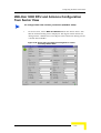
WALKair 3000 RFU and Antenna Configuration from Sector View 4-87
Configuring RFU and Antenna Parameters from BS-BU View (WALKair 1000
only) 4-91
Configuring TS-BU RFU & and Antenna Parameters (WALKair 1000 only)
4-93
Chapter 5 - Shelf Management
Hot Swap Controller Management ......................................................... 5-2
Creating Hot Swap Controller Cards ................................................ 5-2
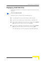
Displaying HSC View ....................................................................... 5-2
Deleting HSCs .................................................................................. 5-5
Modifying HSC Properties ................................................................ 5-5
Moving HSC Slot Positions .............................................................. 5-7
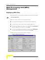
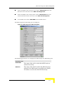
Main Processing Unit (MPU) Management ............................................ 5-8
Displaying MPU View ....................................................................... 5-8
WALKnet User’s Manual
3
Contents
Deleting MPUs ............................................................................... 5-10
Modifying MPU Properties ............................................................. 5-10
Saving an MPU Configuration ........................................................ 5-13
Uploading and Downloading an MPU Configuration ...................... 5-14
Accessing Software Reset Management ....................................... 5-16
Moving MPU Slot Positions ............................................................ 5-16
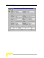
Network Interface Unit Management ................................................... 5-17
Creating Network Interface Units ................................................... 5-17
Displaying ATM-NIU View .............................................................. 5-17
Displaying 12xE1-NIU View ........................................................... 5-21
Displaying E3-NIU View ................................................................. 5-25
Deleting NIUs ................................................................................. 5-28
Modifying NIU Properties ............................................................... 5-28
Moving NIU Slot Positions .............................................................. 5-31
Accessing Software Reset Management ....................................... 5-31
Configuring ATM or E1 or E3 Interfaces ........................................ 5-31
Intermediate Frequency Unit (IFU) Management ................................ 5-32
Displaying IFU View ....................................................................... 5-32
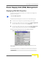
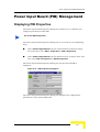
Power Supply Unit (PSU) Management ............................................... 5-35
Displaying PSU Edit Properties ...................................................... 5-35
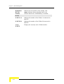
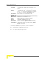
Power Input Board (PIB) Management ................................................ 5-37
Displaying PIB Properties .............................................................. 5-37
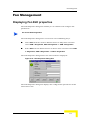
Fan Management ................................................................................... 5-39
Displaying Fan Edit properties ....................................................... 5-39
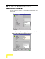
Chapter 6 - Telecom Port Configuration
WALKair 1000 Interfaces Configuration Parameters ........................... 6-2
4
WALKnet User’s Manual
Contents
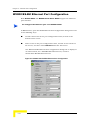
Changing the Configured Port Type ................................................. 6-3
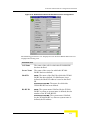
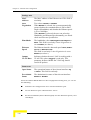
Modifying Port Configuration Parameters ........................................ 6-5
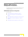
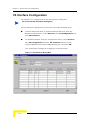
WALKair 3000 Interfaces Configuration Parameters ......................... 6-17
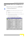
W3000 BS-BU Interfaces Configuration ......................................... 6-17
W3000 TS-BU Interfaces Configuration ......................................... 6-37
Chapter 7 - System Services Configuration
WALKair 1000 License Management ..................................................... 7-2
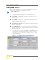
WALKair 1000 Leased Line Service Management ................................ 7-4
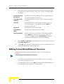
Adding Leased Line Services ........................................................... 7-6
Editing Leased Line Services ........................................................... 7-9
Deleting Leased Line Services ...................................................... 7-10
WALKair 1000 V5 Configuration .......................................................... 7-11
V5 Interface Configuration ............................................................. 7-12
V5 Subscribers ............................................................................... 7-19
V5 Global Parameters .................................................................... 7-25
WALKair 1000 Frame Relay and Ethernet Configuration .................. 7-26
Frame Relay Overview ................................................................... 7-26
Ethernet Overview .......................................................................... 7-26
Configuring Frame Relay and Ethernet .......................................... 7-26
Frame Relay Logical Port Configuration ........................................ 7-27
Frame Relay/Ethernet Service Configuration ................................. 7-34
WALKair 3000 Client Management ...................................................... 7-47
Adding Clients ................................................................................ 7-50
Editing Clients ................................................................................ 7-52
Deleting Clients .............................................................................. 7-53
WALKair 3000 IP SLA Management ..................................................... 7-55
WALKnet User’s Manual
5
Contents
Adding IP SLA ................................................................................ 7-60
Editing IP SLAs .............................................................................. 7-64
Deleting IP SLAs ............................................................................ 7-66
WALKair 3000 TDM SLA Management ................................................ 7-68
Adding TDM SLAs .......................................................................... 7-72
Editing TDM SLAs .......................................................................... 7-75
Deleting TDM SLAs ........................................................................ 7-76
WALKair 3000 Service Management .................................................... 7-78
Adding IP Services ......................................................................... 7-81
Editing IP Services ......................................................................... 7-86
Deleting IP Services ....................................................................... 7-86
Adding TDM Services .................................................................... 7-88
Editing TDM Services ..................................................................... 7-92
Deleting a TDM Service ................................................................. 7-94
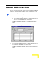
WALKair 3000 Show Clients ................................................................. 7-95
Chapter 8 - Performance Monitoring
WALKair 1000 Air Performance Monitoring .......................................... 8-2
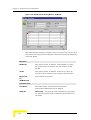
Air Performance Summary ............................................................... 8-2
Detailed Air Performance ................................................................. 8-6
WALKair 3000 Air Performance Monitoring ........................................ 8-11
Air Performance Summary ............................................................. 8-11
Detailed Air Performance ............................................................... 8-15
V5 Call Statistics .................................................................................... 8-20
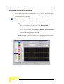
Performance Data Collection ............................................................... 8-24
Viewing the Collection Process ...................................................... 8-26
6
WALKnet User’s Manual
Contents
Configuring Performance Data Collection ...................................... 8-35
Frame Relay Statistics .......................................................................... 8-39
Port Signaling Statistics ................................................................. 8-39
End Point Traffic Statistics ............................................................. 8-46
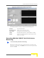
WALKair 3000 IP SLA Performance Monitoring ................................. 8-50
Accessing IP SLA Performance Monitoring ................................... 8-50
Executing WALKair 3000 IP SLA Performance Monitoring ............ 8-51
Chapter 9 - Security Management
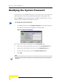
Modifying the System Password ........................................................... 9-2
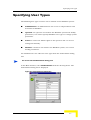
Specifying User Types ............................................................................ 9-3
Adding New Users ........................................................................... 9-4
Editing Users .................................................................................... 9-5
Deleting Users .................................................................................. 9-5
Chapter 10 - Utilities
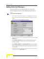
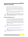
Authorized Managers ............................................................................ 10-2
Software Download ............................................................................... 10-7
Multiple BS-BU Download .............................................................. 10-7
Single Device Download .............................................................. 10-16
Configuration Upload and Download ................................................ 10-19
WALKair 1000 Configuration Upload and Download ................... 10-19
Creating Configuration Files ......................................................... 10-21
Loading Configuration .................................................................. 10-23
WALKair 3000 Shelf Configuration Upload and Download .......... 10-24
WALKair 3000 Stand-Alone BS-BU Configuration Upload and Download
10-25
Versions and Reset Management ...................................................... 10-27
WALKair 1000 Software Versions ................................................ 10-27
WALKnet User’s Manual
7
Contents
WALKair 3000 Software Versions ................................................ 10-33
Performing BER Tests ........................................................................ 10-44
Configuring SNMP Parameters .......................................................... 10-48
Chapter 11 - HPOV Customization
Integration Overview ............................................................................. 11-2
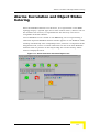
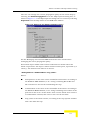
Alarms Correlation and Object Status Coloring ................................. 11-3
Disabling a Correlation Policy ........................................................ 11-9
Access to WALKair Base Station Element View .............................. 11-12
Chapter 12 - The WALKnet Alarm Browser
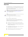
Overview ................................................................................................. 12-2
Alarm Browser Windows ...................................................................... 12-4
Manipulating Alarms ............................................................................. 12-9
Sorting Alarms ................................................................................ 12-9
Acknowledging Alarms ................................................................. 12-11
Deleting Alarms ............................................................................ 12-13
Saving an Alarms File .................................................................. 12-14
Opening an Alarms File ................................................................ 12-16
Requesting Active Alarms for a Device ........................................ 12-17
Closing the WALKnet Alarm Browser Windows ........................... 12-24
Appendix A - WALKair 1000 Trap Descriptions
8
WALKnet User’s Manual
Contents
Appendix B - WALKair 3000 Trap Descriptions
General Comments ..................................................................................B-2
Telecom Interface Traps .........................................................................B-3
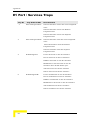
E1 Port / Services Traps .........................................................................B-4
E3 Port / Services Traps ........................................................................B-5
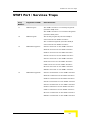
STM1 Port / Services Traps ...................................................................B-7
Devices Traps ..........................................................................................B-8
Hardware Traps .......................................................................................B-9
IFU Traps ................................................................................................B-10
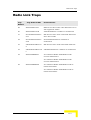
Radio Link Traps ...................................................................................B-11
RFU Traps ..............................................................................................B-12
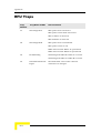
IF MUX Traps ..........................................................................................B-13
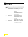
Software Traps .......................................................................................B-14
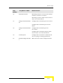
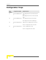
Configuration Traps ..............................................................................B-16
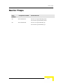
Sector Traps ...........................................................................................B-17
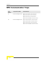
MPU Communication Traps ..................................................................B-18
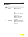
Shelf Traps .............................................................................................B-19
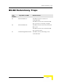
BS-BU Redundancy Traps ....................................................................B-21
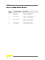
Service/SLA/Client Traps ......................................................................B-22
Clock Control Traps ..............................................................................B-23
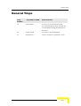
General Traps ........................................................................................B-25
Appendix C - WALKair 1000 Error Messages
WALKair 1000 Error Messages ..............................................................C-2
WALKnet User’s Manual
9
Contents
This page left intentionally blank.
10
WALKnet User’s Manual
1
Chapter 1 - Introduction to WALKnet
In This Chapter
“Overview” on page 1-2
“System Requirements” on page 1-5
“Installing WALKnet” on page 1-7
“Connecting WALKnet to a Database” on page 1-13
“Defining the Environmental Variable for Log Files” on page 1-16
“SNMP MIBs Supported by WALKnet” on page 1-19
Chapter 1 - Introduction to WALKnet
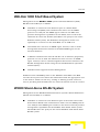
Overview
WALKnet is a management application that provides a graphical
representation of the WALKair 1000 (version 3.10 and higher) and/or
WALKair 3000 systems, and enables their configuration and maintenance.
WALKnet is a user-friendly application that runs on MicrosoftTM Windows
NT/2000/XP and UNIX platforms.
The WALKnet application uses the same concepts and terms as defined in
the WALKair 1000 System Description and WALKair 3000 System
Description. This manual assumes prior familiarity with these documents.
WALKair 1000 System
Management of the WALKair 1000 system's Network Elements (Base
Station Basic Units and Terminal Station Basic Units) is as follows:
WALKnet is connected to the Ethernet port of a Base Station Basic
Unit (BS-BU) and communicates with the BS-BU using the SNMP
protocol over UDP/IP. The SNMP agent resides in each BS-BU, and
provides management capabilities for the BS-BU and all connected
Terminal Station Basic Units (TS-BUs).
The BS-BU is the SNMP proxy for all the TS-BUs.
A BS-BU communicates with the TS-BUs via an Alvarion proprietary
protocol over an air link. The TS-BU does not have an SNMP agent.
Instead, it has a small management kernel that interfaces the BS-BU
SNMP agent using the air-link Embedded Operation Channel (EOC).
WALKnet sends all SNMP queries to the WALKair 1000 BS-BU. The BS-BU
encodes the requests and collects the information from the appropriate
TS-BU.
1-2
WALKnet User’s Manual
Overview
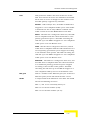
WALKair 3000 Shelf-Based System
Management of the WALKair 3000 system's Network Elements (Shelf,
BS-BUs and TS-BUs) is as follows:
WALKnet is connected to the Ethernet port of a Shelf's Main
Processing Unit (MPU) and communicates with it via the SNMP
protocol over UDP/IP. The SNMP agent resides in the MPU and
provides management capabilities for the Shelf, other cards in the
shelf and all connected TS-BUs (The MPU is the proxy for the entire
WALKair 3000 system). The WALKnet management station can
optionally be connected to the shelf MPU via an ATM card.
The BS-BU does not have an SNMP agent. Instead, it has a small
management kernel that interfaces the MPU SNMP agent via the
internal Shelf bus.
A BS-BU communicates with the TS-Bus via an Alvarion proprietary
protocol over an air link. The TS-BU also does not have an SNMP
agent. Instead, it has a small management kernel that interfaces the
BS-BU management kernel using the air-link Embedded Operation
Channel (EOC).
WALKair 3000 supports In Band Management.
WALKnet sends all SNMP queries to the WALKair 3000 MPU. The MPU
encodes the requests and collects the information from the appropriate card
in the shelf or TS-BU. In this way, viewing or defining system resources
and/or providing fault identification are achieved with the touch of a button.
W3000 Stand-Alone BS-BU System
Management of the WALKair3000 Stand-Alone system's Network Elements
(BS-BU and TS-BUs) is as follows:
WALKnet is connected to the Ethernet port of the main board of the
Stand-Alone BS-BU and communicates with it via the SNMP protocol
over UDP/IP. The SNMP agent resides on the main board and provides
management capabilities for the WalkAir 3000 Stand-Alone system.
The BS-BU SA is the proxy for the entire WALKair 3000 Stand-Alone
BS-BU system.
WALKnet User’s Manual
1-3
Chapter 1 - Introduction to WALKnet
A Stand-Alone BS-BU communicates with the TS-Bus via an Alvarion
proprietary protocol over an air link. The TS-BU does not have an
SNMP agent. Instead, it has a small management kernel that
interfaces the BS-BU management kernel using the air-link Embedded
Operation Channel (EOC).
The WALKair 3000 Stand-Alone BS-BU supports In Band Management
through the second Ethernet port.
WALKnet sends all SNMP queries to the WALKair 3000 Stand-Alone
BS-BU. The BS-BU encodes the requests and collects the information
from the appropriate TS-BUs (if required). In this way, viewing or
defining system resources and/or providing fault identification are
achieved with the touch of a button.
1-4
WALKnet User’s Manual
System Requirements
System Requirements
The WALKnet workstation and application requirements are as follows:
Ethernet Network Card
Windows Platform
Processor: IBM Compatible PC with Pentium IV CPU, 1.2 GHz
Operating System: Microsoft Windows NT 4.0/2000/XP
Memory: 1 GB RAM
Hard Disk: 6 GB
19 inch monitor
Screen Resolution: 1024 x 768 pixels
Font Size: small fonts
Color Palette: 16777216 colors
Microsoft Internet Explorer Version 5.5 or higher -Or- Netscape
Version 4.5 or higher for On-Line Help
CD Drive
WALKnet User’s Manual
1-5
Chapter 1 - Introduction to WALKnet
UNIX Platform
Processor: Sun Fire V210 Server
Operating System: Sun Solaris, Version 2.8 and 2.9
Memory: 1 GB RAM
Hard Disk: 9 GB
Netscape Version 7.0 for On-Line Help
U.W.SCSI-2
CD Drive.
Note
Database requirements: See “Connecting WALKnet to a Database” on
page 1-13.
1-6
WALKnet User’s Manual
Installing WALKnet
Installing WALKnet
WALKnet is installed on either Windows NT/2000/XP or UNIX. WALKnet
can also be installed either over HP OpenView (Network Node Manager
Version 6.4) or as a standalone application.
Note
When WALKnet is installed as a standalone application, SNMP Trap functionality is
available from the WALKnet Alarm Browser. See “The WALKnet Alarm Browser”
on page 12-1.
The following procedure describes how to install WALKnet on Windows
NT/2000/XP and UNIX platforms. It does not describe the installation of HP
OpenView (HPOV). For instructions on the installation of HP OpenView,
please see the instructions supplied by Hewlett Packard. After installation of
HP OpenView, test the HP OpenView Discover Your Network and perform a
map layout.
Installing WALKnet on Windows
The installation procedure is a standard Windows installation with
easy-to-follow, on-screen instructions.
To install WALKnet:
1
Install HP OpenView, if required.
2
Insert the WALKnet CD into your computer's CD-ROM drive.
3
Navigate to the WALKnet directory. Double-click the WALKnet.exe file
to invoke the WALKnet installation wizard.
4
Follow the on screen instructions. During the installation procedure,
you must select Standalone, HPOV or both. The HPOV option is only
available if HP OpenView is installed on your computer.
WALKnet User’s Manual
1-7
Chapter 1 - Introduction to WALKnet
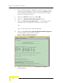
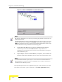
5
If WALKnet is installed over HP Open View, the traps must be
customized as follows: Open a DOS console window and navigate to
the <OpenView home directory>\bin, and perform the ovw - fields
commands.
Notes
The installation of WALKnet over HPOV customizes the HPOV. Refer to Chapter 11,
“HPOV Customization”, for more details.
If a previous version of WALKnet is installed on your computer, remove it and restart your
computer before installing this version of WALKnet.
Installing WALKnet on UNIX
The installation CD includes the following files:
Readme.txt, which includes installation instructions
wlkntfl.zip, which contains WALKnet software
To install WALKnet:
1
Log on to Your UNIX Machine with root privileges, and copy the
following WALKnet files to a temporary directory (e.g. /home/tmp):
wlkntfl.zip
readme.txt
2
Navigate to the temporary directory and unzip the wlkntfl.zip file.
3
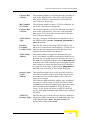
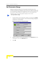
On the Unix terminal, verify you current User and Environment.
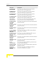
4
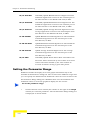
* For HP Open View Integration only (otherwise proceed to the next
step), modify your environment variable LD_LIBRARY_PATH
according to the following format:
>source <Hpov_root>/OV/bin/ov.envvars.csh, where <Hpov
root> is the directory where HP Open View is installed
>setenv LD_LIBRARY_PATH $OV_LIB
1-8
WALKnet User’s Manual
Installing WALKnet
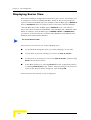
Following is an example screen.
Figure 1-1: LD_LIBRARY_PATH Environment Variable
Note
It is recommended to put those variables in the .cshrc file (for C shell users) or
.login /.profile for other shell users.
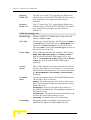
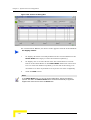
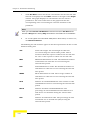
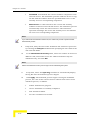
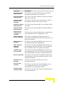
5
Check that the variables have been modified. An example screen is
shown below.
Figure 1-2: Variable Update Check
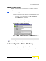
6
In the temporary directory where the WALKnet installation files are
stored, run the installation script by typing ./unix_install.
At the prompt, enter the full path for installation: for example,
/opt/Walknet7_5.
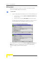
7
When the GeNMS Wizard opens, click on the Next button. Choose the
Network Platform by clicking the relevant check box: Stand Alone or
HPOV. You can also choose both platforms by checking both check
boxes (Stand Alone and HPOV). Click on the Next button to proceed.
WALKnet User’s Manual
1-9
Chapter 1 - Introduction to WALKnet
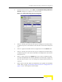
8
When the window appears displaying a summary of your settings,
check that the information is correct. Click on the Create button to
proceed with the installation. Approve any messages that appear
during the installation process.
9
Approve the Notice message (by clicking OK).
10
Approve the Wizard Finished Successfully message.
11
When the "Select the Oracle8i version……" line appears on the
terminal, if you are using Oracle, select the correct version.
OR—
If you are not using Oracle, select "6" (default).
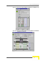
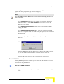
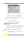
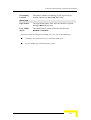
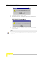
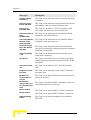
12
When the "Do you want to perform WALKair/HPOV integration"
message appears, type y or n, as required.
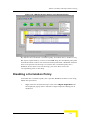
Figure 1-3: WALKnet/HPOV Integration
13
Follow the process until the *******Installation Complete****
message appears.
1-10
WALKnet User’s Manual
Installing WALKnet
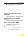
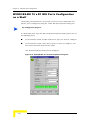
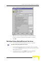
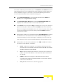
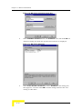
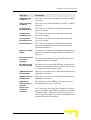
14
*For HP Open View integration only (otherwise proceed to the following
step), run the >ovw -fields command, as shown below.
Figure 1-4: ovw -fields command for HP Open View
Perform trap integration using the following command:
>xnmevents -merge <WALKnet_root>Install/HPOV/traps.dat
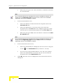
15
Enable Read & Write privileges to all Unix Users using the following
command:
>chmod 775 <walknet_root>/Projects/FLOWARE/
WALKNet/Ver1_0/Product/Data/AsciiDb/WALKNetMaps
WALKnet User’s Manual
1-11
Chapter 1 - Introduction to WALKnet
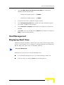
Post installation
After WALKnet has been successfully installed, but before it is invoked, you
must perform the following tasks:
To connect the management station to a WALKair 1000 BS BU, or a
WALKair 3000 Stand-Alone BS-BU, define the following IP parameters
on the BS-BU using the Local Craft Interface (LCI):
IP Address
Network Mask
Default IP Gateway Address
In order to connect the management station to the WALKair 3000
Shelf, define the following IP parameters on the MPU using the LCI:
IP Address
Network Mask
Default IP Gateway Address
1-12
WALKnet User’s Manual
Connecting WALKnet to a Database
Connecting WALKnet to a Database
This section requires some basic knowledge about relational databases and
their installation.
WALKnet uses a relational database to store air link performance data and
BS-BU configurations. The latter are stored in the local file system if a
database is not defined. The environment variable NMS_DB_NAME defines
the database to WALKnet.
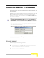
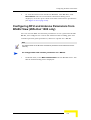
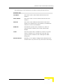
Note
Accessing the Environment Variable - On your PC, Select Settings, then
Control Panel. In the Control Panel, double-click on the System icon. In the System
Properties Window, select the Advanced tab. Click the Environmental Variables
button.
-OrRight -click on the My Computer icon, select Properties, Advanced Tab, and then
click on Environmental Variables.
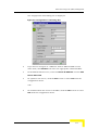
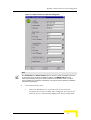
Figure 1-5: Database Environment Variable (example - Microsoft Access)
In order to establish connectivity between WALKnet and the database,
database user accounts (Oracle8i only) must be established and WALKnet's
environment must be set.
Product Support
WALKnet supports the following databases:
Oracle version 8.1.6 and higher. The Oracle server can be hosted
either on SUN Solaris or Windows NT/2000/XP.
Microsoft Access on NT/2000/XP.
WALKnet User’s Manual
1-13
Chapter 1 - Introduction to WALKnet
Connecting to Microsoft Access
To connect to Microsoft Access:
1
Using any name, define an ODBC data source name that uses the
Microsoft Access ODBC driver. Create the database in the process.
2
Set the NMS_DB_NAME environment variable to:
ODBC/<Your Data Source Name>
Connecting to Oracle8i
You can connect to an Oracle8i database from both WALKnet for Windows
NT/2000/XP and WALKnet for UNIX. The Oracle8i server can be hosted
either on Windows NT/2000/XP or UNIX.
WALKnet connects to Oracle8i with the user ID and password used to log in
to it. A WALKnet user must also be created as an Oracle8i user to be able to
connect to Oracle8i. The WALKnet admin user must be created before
WALKnet is run for the very first time, and should be granted table creation
permissions. Therefore the following procedure must be performed (creating
user tables).
To create user tables in the database:
1
Edit the sql file oracle8.sql, and the replace the sample lines to match
your system.
2
Execute the following SQLPLUS command:
SQL> start oracle8
To connect to an Oracle8i server from WALKnet for Windows:
1
Install the Oracle8i NT/2000/XP Client software.
2
Set the NMS_DB_NAME environment variable to oracle81/
<net service name>.
To connect to an Oracle8i server from UNIX:
1-14
WALKnet User’s Manual
Connecting WALKnet to a Database
1
If the Oracle8i server is on a different workstation, install the Oracle8i
client.
2
Set the NMS_DB_NAME environment variable to oracle81/<net
service name>.
3
Prepend the path of the Oracle library directory to the
LD_LIBRARY_PATH environment variable.
Database Size Requirements
The Air Link Performance Data Collection process inserts 96 records per
BS-BU/TS-BU air link, per day. The record size for Microsoft Access is 140
bytes. The record size for Oracle8i is 300 bytes.
WALKnet Customization for UNIX
This customization requires some basic knowledge about UNIX
administration.
After successfully installing WALKnet, the user login file should be modified
so that the path variable includes the directory into which WALKnet was
installed. To run WALKnet, enter the command Run_WALKnet.
Note
To enable the Help browser, set the GeNMS_UNIX_EXT_HELP_VIEWER
environment variable to the full path name of the browser.
WALKnet User’s Manual
1-15
Chapter 1 - Introduction to WALKnet
Defining the Environmental Variable
for Log Files
You need to define an environmental variable in order to save WALKnet log
files. When defining the variable you include a directory path under which
WALKnet will create the following directories for the log files:
SDL - includes software download files (see “Displaying the Software
Download Log” on page 10-13)
BER_Test - includes BER test results (“Performing BER Tests” on
page 10-44)
Audit_Log - includes user login information files (see “Starting
WALKnet” on page 2-2)
Trap - includes WALKnet Alarm Browser files (if this option is used).
(See “Saving an Alarms File” on page 12-14
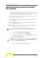
To define an environmental variable for the WALKnet Log Files:
1
On your PC, Select Settings, then Control Panel.
2
In the Control Panel, double-click on the System icon.
3
In the System Properties Window, select the Advanced tab. Click the
Environmental Variables button.
Note
Alternately, right -click on the My Computer icon, select Properties, Advanced Tab,
and then click on Environmental Variables.
The Environmental Variables Dialog Box is displayed.
1-16
WALKnet User’s Manual
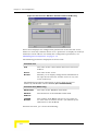
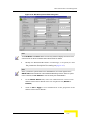
Defining the Environmental Variable for Log Files
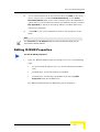
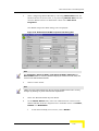
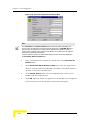
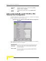
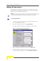
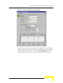
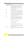
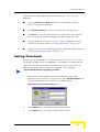
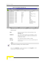
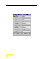
Figure 1-6: Environmental Variables Dialog Box
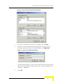
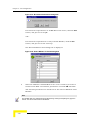
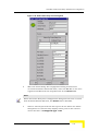
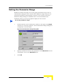
4
In the User variables area (top area of dialog box), click New.
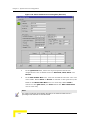
5
In the New User Variable dialog box displayed as below, type the
following variable name in the Variable Name area: NMS_LOG.
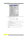
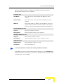
Figure 1-7: New User Variable Dialog Box
In the Variable Value area, type in the name of the directory path that
will include the WALKnet Log File directories created by WALKnet: for
example, c:\WALKnet.
6
Click OK.
WALKnet User’s Manual
1-17
Chapter 1 - Introduction to WALKnet
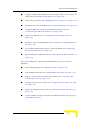
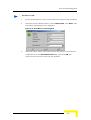
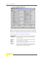
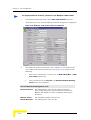
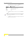
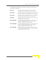
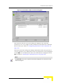
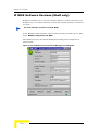
The Environmental Variables Dialog Box is updated.
Figure 1-8: Environmental Variables Dialog Box (updated)
7
If you are running Windows NT, close WALKnet and then restart your
PC.
-OrIf you are running Windows 2000 or Windows XP, close WALKnet and
then restart WALKnet.
1-18
WALKnet User’s Manual
SNMP MIBs Supported by WALKnet
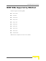
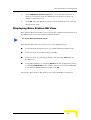
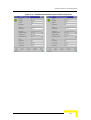
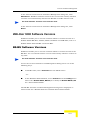
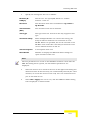
SNMP MIBs Supported by WALKnet
WALKnet supports the following MIBs:
Rfc1213.mib
ianaif.mib
rfc1604.mib
walk_ro.mib
walk_tc.mib
walkair.mib
walkv5.mib
rfc2514.mib
rfc2515.mib
walkair3k.mib
MIBs should be compiled in the above order in HPOV.
WALKnet User’s Manual
1-19
Chapter 1 - Introduction to WALKnet
This page left intentionally blank.
1-20
WALKnet User’s Manual
2
Chapter 2 - Getting Started
In This Chapter
“Starting WALKnet” on page 2-2
“WALKnet Main Window” on page 2-4
“WALKnet Navigation Model” on page 2-15
“Error Information” on page 2-22
“Updating Information” on page 2-23
If you are already familiar with the application, go to Chapter 4, “Cell
Configuration,” for more detailed instructions about procedures.
Chapter 2 - Getting Started
Starting WALKnet
The procedure for starting WALKnet varies according to whether it is
installed over HP OpenView or as a standalone application.
When installed over HP OpenView, invoke WALKnet from HP
OpenView by selecting Run_WALKNet from the HP OpenView Main
menu.
When installed as a standalone application over HP OpenView, invoke
WALKnet, as described below.
When installed over HP OpenView as a standalone application, you can
invoke WALKnet using either of the above methods.
To start WALKnet without HP OpenView on UNIX:
When WALKnet is installed on UNIX, WALKnet is invoked by activating
Run_WALKnet from the installation directory.
To start WALKnet without HP OpenView on Windows:
1
From the Windows Start menu, select Programs > WALKnet >
WALKnet. The WALKnet Login dialog box is displayed as shown
below:
Figure 2-1: WALKnet Login Dialog Box
2-2
WALKnet User’s Manual
Starting WALKnet
WALKnet tracks your Logins and keeps the results in log files. Log files are
named Access_WALKNet.txt and placed in the directory defined by the
NMS_LOG environment variable, sub-directory Audit_Log.
Notes
For information about how to define the NMS_LOG Environment Variable,
see “Defining the Environmental Variable for Log Files” on page 1-16.
Access to the WALKair system from WALKnet requires authentication.
An administrator user configures the user name and password. The
default user name is admin and the default password is ad. Refer to
Chapter 9, “Security Management”, for details.
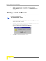
2
Enter your User Name and Password, and click OK. The WALKnet
Main window is displayed.
Figure 2-2: WALKnet Main Window
The WALKnet Main window is described in the following section.
WALKnet User’s Manual
2-3
Chapter 2 - Getting Started
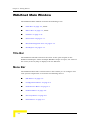
WALKnet Main Window
The WALKnet Main window includes the following areas:
“Title Bar” on page 2-4, below.
“Menu Bar” on page 2-4, below.
“Toolbar” on page 2-10.
“Status Bar” on page 2-11.
“Network Navigation Tree” on page 2-12.
“Workspace” on page 2-13.
Title Bar
The WALKnet Title Bar indicates the name of the open map file in the
WALKnet Workspace. When multiple WALKnet maps are open, the name of
the active (in-focus) map is displayed in the Title Bar.
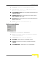
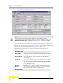
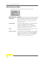
Menu Bar
The WALKnet Menu Bar contains menus that enable you to configure and
view system components. It includes the following menus:
“File Menu” on page 2-5.
“Configuration Menu” on page 2-6.
“Performance Menu” on page 2-7.
“Utilities Menu” on page 2-8.
“Security Menu” on page 2-8.
“Fault Menu” on page 2-9
2-4
WALKnet User’s Manual
WALKnet Main Window
“Help Menu” on page 2-9.
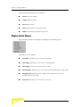
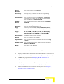
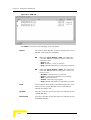
File Menu
The File menu includes the following options:
New Map: Enables you to create a new map.
Open Map: Enables you to open an existing map.
Save Map: Saves the current map in a file.
Save Map As: Enables you to save the open map file with a new name.
Background: Enables you to change the image file used as the
background for the map.
Login: Enables you to log in as a different user.
Exit: Exits from the WALKnet application, saving any configuration
changes.
WALKnet User’s Manual
2-5
Chapter 2 - Getting Started
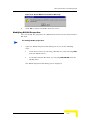
Configuration Menu
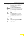
The Configuration menu includes the following options:
New Cell: Enables you to create a new cell.
Cell: Enables you to open Cell View for a selected cell.
Sector: Enables you to open Sector View for a selected sector.
Shelf: Enables you to open Shelf View for a selected shelf.
W3000 Shelf: Enables you to open BS-BU, Main Processing Unit
(MPU), Network Interface Unit (ATM-NIU) or Hot Swap Controller (HSC)
Views for a selected Shelf component.
W3000 BS-BU/SA: Enables you to open WALKair 3000 for a
Stand-Alone BS-BU.
W1000 BS-BU: Enables you to open WALKair 1000 for a selected
BS-BU.
Goto Terminal: Enables you to open TS-BU View for a selected
TS-BU.
Terminals: Enables you to display the Terminal Stations registered to
a selected BS-BU.
2-6
WALKnet User’s Manual
WALKnet Main Window
Frequencies: Enables you to assign frequencies to BS-BUs.
RFU and Antenna: Enables you to configure RFU and antenna
parameters for BS-BUs and TS-BUs.
Authorized Managers: Enables you to define Trap destinations and
authorized managers.
W3000 Services: Enables you to define services between telecom
ports of a WALKair 3000 system.
Services: Enables you to define services between telecom ports of a
WALKair 1000 system.
Refresh: Updates the status of devices on the map.
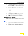
Performance Menu
The Performance menu includes the following options:
Air: Provides access to a summary of air performance and detailed
statistics of air performance.
Call Statistics: Provides access to V5 call statistics.
Frame Relay: Provides access to Frame Relay statistics.
Collection: Provides access to the air performance monitoring
collection.
IP SLA Performance: Provides access to IP SLA monitoring.
WALKnet User’s Manual
2-7
Chapter 2 - Getting Started
Utilities Menu
The Utilities menu includes the following options:
Tests: Enables you to perform BER tests.
Software Download: Enables you to perform software downloads to
devices.
Configuration Load: Enables you to download and upload WALKair
3000 and WALKair 1000 BS-BU configuration parameters.
Versions: Enables you to view resident software versions on devices.
SNMP Parameters: Enables you to specify SNMP parameters.
Security Menu
The Security menu includes the following options:
Authorization: Enables you to view a list of users and define new
users.
Change Password: Enables you to change the WALKnet access
password.
2-8
WALKnet User’s Manual
WALKnet Main Window
Fault Menu
The Fault menu is used to access displayed alarms in the WALKnet Alarm
Browser, and only appears if HP OpenView is not installed (or installed and
not running) in the system.
The Fault menu includes the following options:
WALKair Alarms Monitor - The WALKair Alarms Monitor Window
displays (in real-time) the most recent twenty SNMP traps (alarms)
sent by WALKair 1000/WALKair 3000 devices, and received by the
WALKnet application.
WALKair Alarms History - The WALKair Alarms History window can
display all the alarms from the devices. Its display is refreshed
manually by the operator.
Note
We recommend to use HP OpenView for large installations. For more information about
HP OpenView integration with WALKnet, see “HPOV Customization” on
page 11-1 of this user’s manual.
For more information about the WALKnet Alarm Browser, see “The WALKnet Alarm
Browser” on page 12-1 of this user’s manual.
Help Menu
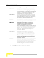
The Help menu includes the following options:
Help Index: Provides access to online help.
About: Displays version information for the WALKnet application.
WALKnet User’s Manual
2-9
Chapter 2 - Getting Started
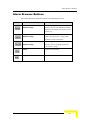
Toolbar
The WALKnet Toolbar contains icons for quick access to key menu options
that enable you to configure and view system components. It includes the
following tools:
New
Enables you to create a new map.
Open
Enables you to open an existing map.
Save
Saves the current map in a file.
Refresh
Enables you to refresh SNMP parameters
manually
View Cell
Enables you to open Cell View for a selected cell.
View Shelf
Enables you to open WALKair 3000 Shelf View for
a selected shelf.
View Sector
Enables you to open WALKair 1000 or WALKair
3000 Sector View for a selected sector according
the sector type.
View BS-BU
Enables you to open WALKair 1000 or WALKair
3000 BS-BU View for a selected BS-BU according
the BS-BU type.
View TS-BU
Enables you to open WALKair 1000 or WALKair
3000 TS-BU View for a selected TS-BU according
the TS-BU type.
View
Enables you to open WALKair 1000 or WALKair
Terminals
3000 Terminal Stations registered to a selected
BS-BU according the BS-BU type.
Sector
Enables you to assign frequencies to WALKair
Frequency
1000 and/or WALKair 3000 BS-BUs in the
selected sector according to the sector type.
2-10
RFU and
Enables you to configure RFU and antenna
Antenna
parameters for WALKair 1000 BS-BUs.
Software
Enables you to perform software downloads to
Download
devices.
WALKnet User’s Manual
WALKnet Main Window
Versions
Enables you to view resident software versions on
devices.
About
Displays version information for the WALKnet
application.
Help
Provides access to online help.
Status Bar
The WALKnet Status Bar indicates the current state of WALKnet while
communicating with devices. It also displays the time and date.
WALKnet User’s Manual
2-11
Chapter 2 - Getting Started
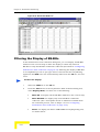
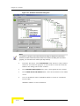
Network Navigation Tree
The WALKnet Network Navigation tree provides a hierarchical view of the
network, displaying all the objects defined on the open map.
Figure 2-3: WALKnet Network Navigation Tree
The color of the icon to the left of each element in the Network Navigation
Tree reflects the status of the element, as follows:
Green: OK, no alarms
Yellow: Minor alarm
Red: Major alarm
Gray: No connection with the device
2-12
WALKnet User’s Manual
WALKnet Main Window
Double-clicking an element in the Network Navigation tree displays the View
window for that element. For example, double-clicking a BS-BU displays
Base Station BU View for the BS-BU.
Use the Find field to locate an object by its name. You can either search all
objects in the Network Navigation tree or you can search objects of a specific
type.
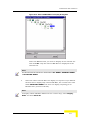
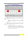
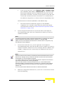
Workspace
The WALKnet Workspace is the main working area of the WALKnet
application. It displays maps that specify cell locations.
Figure 2-4: WALKnet Workspace
The cell icon, positioned on a.GIF background image of an area, indicates
the geographical location of a WALKair cell. The color of the cell icon alerts
the user to the general status of the devices within the cell. The color of the
base of the cell icon
reflects the status of the indoor equipment and
the color of the antenna waves
WALKnet User’s Manual
reflects the status of the air link.
2-13
Chapter 2 - Getting Started
The cell color indications are as follows:
Green: OK, no alarms
Yellow: Minor alarm
Red: Major alarm
Gray: All elements are disconnected
White: No defined elements in the cell
Right-click Menu
Right-clicking inside the Workspace displays the following menu:
The options are as follows:
New Map: Enables you to create a new map.
Open Map: Enables you to open an existing map.
Save Map: Saves the current map in a file.
Save Map As: Enables you to save the open map file with a new name.
Background: Enables you to change the image file used as the
background for the map.
New Cell: Enables you to create a new cell.
2-14
WALKnet User’s Manual
WALKnet Navigation Model
WALKnet Navigation Model
The WALKnet application uses a combination of look-down and
look-through methods, which provides both overall and specific views of the
WALKair system. To display and manage the WALKair network, a
hierarchical navigation model is used whereby you drill down from the cell
icons through the hierarchy of devices, as follows:
At each level, the parameters and configuration information are displayed in
a View of that level, as follows:
WALKnet User’s Manual
2-15
Chapter 2 - Getting Started
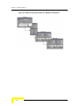
Figure 2-5: WALKnet Navigation Model for WALKair 1000 System
2-16
WALKnet User’s Manual
WALKnet Navigation Model
Figure 2-6: WALKnet Navigation Model for WALKair 3000 Shelf-based System
WALKnet User’s Manual
2-17
Chapter 2 - Getting Started
Figure 2-7: WALKnet Navigation Model for WALKair 3000 Stand-Alone System
At each level or View, you can view and edit the properties of the device, as
well as access the child or sub-elements of the device.
2-18
WALKnet User’s Manual
WALKnet Navigation Model
Horizontal Navigation
Additionally, the WALKnet navigation model enables you to navigate
horizontally in all hierarchical levels.
Cell
Cell
Cell
Shelf
Shelf
Shelf
Sector
Sector
Sector
BS-BU
BS-BU
BS-BU
TS-BU
TS-BU
TS-BU
MPU
MPU
MPU
NIU
NIU
NIU
HSC
HSC
HSC
This means you can move between Views, as follows:
When you are in Cell View for a selected cell, you can display the Cell
View information for another cell in the same map without closing Cell
View.
When you are in Shelf View for a selected shelf, you can display the
Shelf View information for another shelf in any cell within the map.
When you are in Sector View for a selected sector, you can display the
Sector View information for another sector in any cell within the map.
When you are in BS-BU or TS-BU View for a selected BS-BU or TS, you
can display the BS-BU or TS-BU View information for another BS-BU
or TS in any sector in any cell within the map.
WALKnet User’s Manual
2-19
Chapter 2 - Getting Started
When you are in MPU, NIU or HSC View for a selected MPU, NIU or
HSC, you can display the MPU, NIU or HSC View information for
another MPU, NIU or HSC in any shelf in any cell within the map.
Horizontal navigation enables rapid movement between cells, Shelves,
sectors, MPUs, NIUs, HSCs, BS-BUs and TS-BUs without having to close
the respective View.
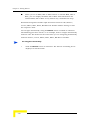
You navigate horizontally using the Browse button available in all Views.
The following procedure shows, as an example, how to navigate horizontally
between cells. The method is the same when you are navigating horizontally
between shelves, sectors, MPUs, NIUs, HSCs, BS-BUs or TS-BUs.
To navigate horizontally:
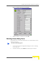
1
Click the Browse button in Cell View. The Browse Cell dialog box is
displayed as shown below:
2-20
WALKnet User’s Manual
WALKnet Navigation Model
Figure 2-8: Browse Cell Dialog Box
2
Expand the tree, and select another cell.
WALKnet User’s Manual
2-21
Chapter 2 - Getting Started
Note
To find a cell in the tree, specify its name in the Find field and click Do Find. If the
specified cell is found, it is selected in the tree.
3
Click OK. The Browse Cell dialog box is closed, and the open Cell View
now displays the configuration of the newly selected cell.
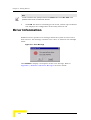
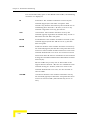
Error Information
WALKnet issues specific error messages when the system receives errors
from a device. The message contains error codes, as shown in the example
below.
Figure 2-9: Error Message
Click Details to display a description of the error message. Refer to
Appendix C, “WALKair 1000 Error Messages” for more details.
2-22
WALKnet User’s Manual
Updating Information
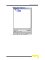
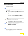
Updating Information
Whenever you open a WALKnet window or dialog box, WALKnet
automatically retrieves the latest data from the devices defined in the
WALKair system and updates the displayed information. You can manually
update the information in WALKnet windows or dialog boxes at any time.
To manually update information:
In the Main window, select Refresh from the Configuration menu, or
press <F3>. The WALKnet application transparently polls Shelves,
BS-BUs and TS-BUs defined in the system and updates the
information displayed in the open map.
Note
Click the Refresh button in an individual dialog box to update the information displayed
in that dialog box..
WALKnet User’s Manual
2-23
Chapter 2 - Getting Started
This page left intentionally blank.
2-24
WALKnet User’s Manual
3
Chapter 3 - Map Management
In This Chapter
“Introduction” on page 3-2
“Creating a New Map” on page 3-3
“Opening an Existing Map” on page 3-5
“Saving Maps” on page 3-6
Chapter 3 - Map Management
Introduction
Maps are displayed in the WALKnet Workspace. Maps display WALKair cells
within a specific geographical area and include the configuration of the
WALKair system. The geographical area is represented in the map by a
background image (GIF file). A map may show an entire county, a city or
only an area within a city. The use of a background image helps with
orientation, but is not required to create a map.
The cell icons, representing the WALKair cells, may be randomly arranged
on the gray default background or specifically positioned on the background
image showing the actual location within a city/area. Cell icon positions are
always displayed in the last saved location in the map.
Maps, including the configuration of the WALKair system, are saved in map
files in the WALKnet database.
Creating Map Background Images
A map background can be any image saved in GIF format. Background
image files are saved in the WALKnet Maps folder in order to be immediately
accessible when creating a new map. See “Creating a New Map” on page 3-3.
To create a map background:
Scan an image and save it as a GIF file in the Maps folder, located in
the WALKnet folder:
(<root>:\...\WALKnet\Maps\*.gif)
3-2
WALKnet User’s Manual
Creating a New Map
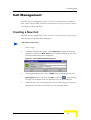
Creating a New Map
A map is created to represent a specific geographical area. The cells for that
area can then be defined. (Defining and configuring cells is described in
Chapter 4, “Cell Configuration.”)
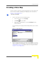
To create a new map:
1
Create a new map in one of the following ways:
From the File menu, select New Map.
Click New
in the toolbar.
Right-click in the Workspace, and select New Map from the
options displayed.
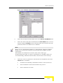
The Open dialog box is displayed with the Maps folder open as shown
below:
Figure 3-1: Open Dialog Box
2
Select a background image for your map, and click Open. The selected
image is displayed in the Workspace. You can now save your map (see
“Saving Maps” on page 3-6) or define cells in your map (described in
Chapter 4, “Cell Configuration”).
WALKnet User’s Manual
3-3
Chapter 3 - Map Management
Note
The size of the background image is fixed. When it is larger than the WALKnet
Workspace, scroll bars enable you to view the entire map. To reduce the size of the
background image, adjust the background image file (.GIF) itself.
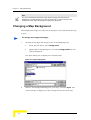
Changing a Map Background
The background image of a map can be changed at any time while the map
is open.
To change the background image:
1
Change the background image in one of the following ways:
From the File menu, select Background.
Right-click in the Workspace, and select Background from the
options displayed.
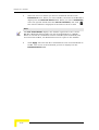
The Open dialog box is displayed as shown below:
Figure 3-2: Open Dialog Box
2
Select a new background image for your map, and click Open. The
selected image is displayed as the background for the open map.
3-4
WALKnet User’s Manual
Opening an Existing Map
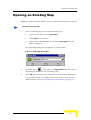
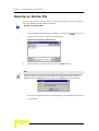
Opening an Existing Map
WALKnet enables multiple maps to be saved and opened whenever required.
To open an existing map:
1
Open an existing map in one of the following ways:
From the File menu, select Open Map.
Click Open in the toolbar.
Right-click in the Workspace, and select Open Map from the
options displayed.
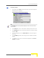
The Open Map dialog box is displayed as shown below:
Figure 3-3: Open Map Dialog Box
2
Click the arrow
to the right of the Map Name field, and select a
map from the dropdown list of existing maps.
3
Click OK. The selected map is displayed in the WALKnet Workspace.
You can now modify the configuration of this map or save it with a
different name. See “Saving a Map with a New Name” on page 3-7.
WALKnet User’s Manual
3-5
Chapter 3 - Map Management
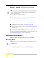
Saving Maps
To prevent the map and its cell configuration from being lost, WALKnet
enables you to save already defined maps with a different name. New maps
should be saved before closing the WALKnet application. This can save time
by enabling you to create a new map with the configuration of an existing
map. In this way, you can modify the configuration rather than defining the
map from the beginning.
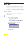
Saving a New Map
New maps should be saved before closing the WALKnet application.
WALKnet automatically prompts you to save any unsaved maps when
exiting the application.
To save a new map:
1
Save a new map in one of the following ways:
From the File menu, select Save Map.
Click Save in the toolbar.
Right-click in the Workspace, and select Save Map from the
options displayed.
The Save Map dialog box is displayed as shown below:
Figure 3-4: Save Map Dialog Box
2
Enter a name for the map (with no blank spaces) in the Map Name
field, and click OK. The map is saved in a map file, and the new name
appears in the Title Bar.
3-6
WALKnet User’s Manual
Saving Maps
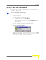
Saving a Map with a New Name
Any existing map, including its cell configuration, can be duplicated and
saved with a different name.
To save a map with a different name:
1
Open an existing map.
2
Save the map in one of the following ways:
From the File menu, select Save Map As.
Right-click in the Workspace, and select Save Map As from the
options displayed.
The Save Map dialog box is displayed as shown below:
Figure 3-5: Save Map Dialog Box
3
Enter a different name for the map (with no blank spaces) in the Map
Name field, and click OK. The map is saved in a map file with the new
name, and the new name appears in the Title Bar.
WALKnet User’s Manual
3-7
Chapter 3 - Map Management
3-8
WALKnet User’s Manual
4
Chapter 4 - Cell Configuration
In This Chapter
“Workflow” on page 4-2
“Cell Management” on page 4-3
“Sector and Shelf Management” on page 4-8
“Base Station Basic Unit Management” on page 4-30
“Terminal Station Basic Unit Management” on page 4-58
“Frequency Planning” on page 4-77
“Configuring the RFU and Antenna” on page 4-82
Chapter 4 - Cell Configuration
Workflow
To monitor and manage the WALKair system, you must first define and
create a representational view of the WALKair system. After creating a map
to represent the geographical area of the WALKair system (described in
Chapter 3, “Map Management”), you create and configure the cells within
the system.
The typical workflow for WALKair 3000 and WALKair 1000 is as follows:
The following sections describe each step of the workflow.
4-2
WALKnet User’s Manual
Cell Management
Cell Management
The first step in configuring a cell is to create a cell and locate it within a
map. Cells can be added, removed and renamed in a map, but they cannot
be transferred between maps.
Creating a New Cell
The first step in configuring a cell is to create a cell. To create a cell, a map
must be open in the WALKnet workspace.
To create a new cell:
1
Open a map.
2
From the Configuration menu, select New Cell, or right-click in the
Workspace and select New Cell from the options displayed. The Cell
Properties Edit dialog box is displayed:
Figure 4-1: Cell Properties Edit Dialog Box
3
In the appropriate fields, enter a Name (with no blank spaces) and
Description for the cell, and click OK. A cell icon
representing
the new cell is displayed in the top-left corner of the workspace.
4
Click the cell icon, and keeping the mouse button pressed, drag it to
the required location on the map as in the example below.
WALKnet User’s Manual
4-3
Chapter 4 - Cell Configuration
Figure 4-2: Locating Cell on Map
You have now defined a cell with no configuration properties. The next step
is to configure the cell by defining sectors within it. See “Sector and Shelf
Management” on page 4-8 for details.
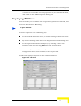
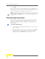
Displaying Cell View
Cell View displays configuration information for a cell and enables you to
configure a cell by defining sectors within it.
To access Cell View:
Cell View is accessed from the Main window in one of the following ways:
In the Network Navigation Tree, by double-clicking a cell node.
In the workspace, by double-clicking a cell.
By right-clicking a cell, and selecting Open from the options displayed.
From the Configuration menu, by selecting Cell or clicking View Cell
in the toolbar. Then browsing to the required cell in the Browse Cell
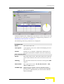
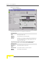
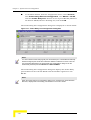
dialog box, and clicking OK.
The Cell View dialog box for the selected cell is displayed:
4-4
WALKnet User’s Manual
Cell Management
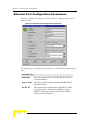
Figure 4-3: Cell View Dialog Box
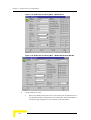
Cell View displays the configuration parameters of the selected cell. The
parameters are read-only. To modify the configuration parameters, see
“Modifying Cell Properties” on page 4-7.
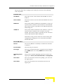
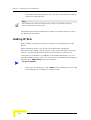
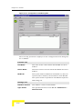
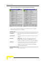
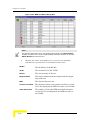
The following Cell View parameters are displayed:
Location area
Name
The name of the cell.
Description
A description of the cell, useful in identifying the location of the cell.
Browse
Enables you to display configuration information in
the open Cell View for another cell in the same map.
List of sectors area
Sector
The name of the sector. The color of the box to the left
of the name indicates the status of devices in the sector.
Heading
The direction in which the antenna is facing: 0 to 360
degrees.
Beam width
The angle of the sector: 15, 30, 45, 60, 90 or 120,
180 and 360 degrees.
IF-MUX Type
W1000 8 Ports, W1000 16 Ports, W3000 6 Ports
(Shelf), W3000 2 Ports (up to 2 Stand-Alone BS-BUs
per sector) or W3000 None (one Stand-Alone BS-BU
without IF MUX).
WALKnet User’s Manual
4-5
Chapter 4 - Cell Configuration
Shelf Name
Shelf only—The system name of the W3000 shelf
within which the IF-MUX is defined.
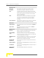
Note
The pie chart to the right of the List of sectors area provides a graphical representation
of the sectors defined in the cell. The color of the sector in the pie chart indicates the
status of devices in the sector.
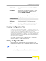
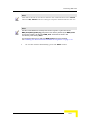
From Cell View, you can do the following:
Display configuration information for another cell in the same map
(see “Horizontal Navigation” on page 2-19)
Edit cell properties (see “Modifying Cell Properties” on page 4-7)
Assign frequencies to BS-BUs (see “Frequency Planning” on page 4-77)
Define new sectors (see “Sector Management” on page 4-8)
Modify and delete existing sectors (see “Deleting and Editing Sectors”
on page 4-14)
Access Sector View (see “Displaying Sector View” on page 4-10)
The next step in configuring a cell is to define the sectors within the cell. See
“Sector and Shelf Management” on page 4-8 for details.
Editing and Deleting Cells
Cells can be deleted from a map or their properties can be modified.
Deleting Cells
Deleting cells from a map also deletes the entire configuration of the cell.
To delete a cell:
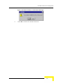
1
In the map, right-click a cell, and select Delete from the options
displayed. The Delete Cell confirmation message is displayed:
4-6
WALKnet User’s Manual
Cell Management
Figure 4-4: Delete Cell Confirmation Message
2
Click Yes to delete the cell from the map.
Modifying Cell Properties
Modifying the properties of a cell enables you to modify the name and
description of the cell.
To modify cell properties:
1
Modify the properties of a cell in one of the following ways:
In the map, by right-clicking a cell, and selecting Properties from
the options displayed.
In Cell View, by selecting Edit Cell from the Cell menu.
The Cell Properties Edit dialog box is displayed:
Figure 4-5: Cell Properties Edit Dialog Box
2
Modify the Name and Description of the cell, as required, and click
OK.
WALKnet User’s Manual
4-7
Chapter 4 - Cell Configuration
Sector and Shelf Management
The following section describes how to create and manage a sector. Shelf
management is described on page 4-19.
Sector Management
The next step in configuring a cell is to define the sectors within the cell. A
cell can include up to 16 sectors.
Creating a Sector
A sector is a division of a cell that contains Base Stations and Terminal
Stations and their respective devices (IF-MUX, RFU and antenna). Sectors
are defined from Cell View, according to the RFUs and antennas located at
the Base Station in your WALKair network. The direction and angle of
coverage of an antenna determine the heading and beam width of a sector.
The number of sectors that can be defined for a cell depends on the antenna
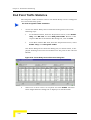
beam width, as follows:
Antenna Beam
Width
Maximum Number
of Sectors
15°
24
30°
12
45°
8
60°
6
90°
4
120°
3
180°
2
360°
1
For detailed descriptions and specifications of antenna types, see the
WALKair System Description.
4-8
WALKnet User’s Manual
Sector and Shelf Management
To create a sector:
1
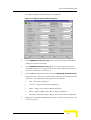
In Cell View, select New from the Sector menu. The Sector Properties
Edit dialog box is displayed:
Figure 4-6: Sector Properties Edit Dialog Box
Note
The Cell Name field is a read-only field that displays the name of the cell for which the
sector is defined.
2
In the Name field, enter a name (with no blank spaces) for the sector.
3
In the Heading field enter the direction in which the antenna is facing,
from 0 to 360.
4
From the dropdown list in the Beam width field, select the angle of
the sector.
5
In the IF-MUX Type field, select the type of the IF-MUX at the Base
Station.
6
Click OK. The new sector is created and is displayed in the List of
sectors in Cell View.
WALKnet User’s Manual
4-9
Chapter 4 - Cell Configuration
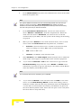
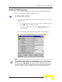
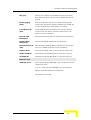
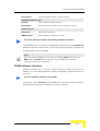
Displaying Sector View
Sector View displays configuration information for a sector and enables you
to configure a sector by defining BS-BUs, within it. Sector View depends
upon the selected IF-MUX type. For example, if the IF-MUX type is W1000 8
Ports or W1000 16 Ports you will see Sector View that contains WALKair
1000 BS-BUs only; if it's IF-MUX type is W3000 6 Ports, you will see a
Sector View that contains both WALKair 1000 BS-BUs and a WALKair 3000
Shelf. In addition, if the IF-MUX type is W3000 2 Ports or W3000 None,
you will see a Sector View that contains both WALKair 1000 BS-BUs and
WALKair 3000 Stand-Alone BS-BUs.
To access Sector View:
Sector View is accessed in one of the following ways:
In the Network Navigation Tree, by double-clicking a sector node.
In Cell View, by double-clicking a sector in the List of sectors.
In Cell View, by selecting a sector in the List of sectors, and selecting
View from the Sector menu.
In the Main window, by selecting Sector from the Configuration menu,
or clicking View Sector in the toolbar. Then browsing to the required
sector in the Browse Sector dialog box, and clicking OK.
Sector View for the selected sector is displayed:
4-10
WALKnet User’s Manual
Sector and Shelf Management
Figure 4-7: Sector View: W1000 IF-MUX, with WALKair 1000 BS-BUs only
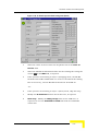
Figure 4-8: Sector View: W3000 IF-MUX, with both WALKair 1000 BS-BUs
and WALKair 3000 Shelf
WALKnet User’s Manual
4-11
Chapter 4 - Cell Configuration
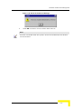
Figure 4-9: Sector View: WALKair 3000 Stand-Alone BS-BU only
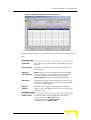
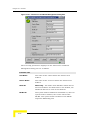
Sector View displays the configuration parameters of the selected sector,
which are read-only. Roll the mouse over a parameter to display its name (if
defined) or its IP address. To modify the configuration parameters, see
“Modifying Sector Properties” on page 4-15.
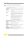
The following parameters displayed in Sector View:
Location area
Cell
The name of the cell for which this sector has been
defined.
Sector
The name of the sector.
Browse
Enables you to display configuration information in
the open Sector View for another sector in any cell
in the same map.
The following parameters will appear in Sector View for sectors
defined by the W3000 6 Ports IF-MUX (for a W3000 Shelf):
Location Area (Shelf-only)
Shelf Name
The name of the WALKair 3000 shelf.
Shelf IP
Address
The IP address of the WALKair 3000 shelf.
IF-MUX
Number
The number of IF-MUXs selected to serve this sector. The value is between 0 and 7 (as defined by the
DIP switch on the IF-MUX).
From Sector View, you can do the following:
4-12
WALKnet User’s Manual
Sector and Shelf Management
Display configuration information for another sector in any cell in the
same map (see “Horizontal Navigation” on page 2-19)
Edit sector properties (see “Modifying Sector Properties” on page 4-15)
Assign frequencies to BS-BUs (see “Frequency Planning” on page 4-77)
Configure RFU and antenna parameters for this sector (see
“Configuring the RFU and Antenna” on page 4-82)
Define new BS-BUs (see “Creating Base Station Basic Units” on
page 4-30)
Modify or delete existing BS-BUs (see “Deleting and Editing BS-BUs”
on page 4-34)
Access Base Station BU View for a selected BS-BU (see “Displaying
Base Station BU View” on page 4-31)
Move a BS-BU to a different slot (see “Moving BS-BU Slot Positions” on
page 4-37)
For sectors defined by a W3000 6 Ports IF-MUX, you also can do the
following:
Edit shelf properties (see “Editing a Shelf” on page 4-16)
Edit IF-MUX properties (see “Edit IF-MUX Properties” on page 4-17)
Define a new chassis card (BU, NIU or HSC) (see “Creating a New
Chassis Slot Card” on page 4-27)
Change the chassis card type (see “Changing Chassis Slot Card Type”
on page 4-27)
Delete an existing chassis card (see “Deleting Chassis Slot Card” on
page 4-27)
Access another chassis card View and Edit Properties (see Chapter 5,
“Shelf Management”)
WALKnet User’s Manual
4-13
Chapter 4 - Cell Configuration
Move a card to a different slot (see “Moving a Card to Another Chassis
Slot in Chassis” on page 4-28)
Access Power Supply Unit properties for a selected Power Supply Unit
card (see Power Supply Unit Management in Chapter 5, “Shelf
Management”)
Access Power Input Board properties (see Power Input Board
Management in Chapter 5, “Shelf Management”)
Access Fan properties (see Fan Management in Chapter 5, “Shelf
Management”)
The next step in configuring a cell in WALKair 1000 system is to define base
units within sectors (see “WALKair 1000 Base Station Basic Unit
Management” on page 4-30 for details).
The next step in configuring a WALKair 3000 system is to configure a shelf
and chassis (see Chapter 5, “Shelf Management”, for details).
Deleting and Editing Sectors
Sectors can be deleted from a cell or their properties can be modified.
Deleting Sectors
Deleting sectors from a cell also deletes the entire sector configuration.
To delete a sector:
1
In Cell View, select a sector in the List of sectors, and select Delete
from the Sector menu. The following Delete Sector confirmation
message is displayed:
Figure 4-10: Delete Sector Confirmation Message
2
4-14
Click Yes to delete the sector from the cell.
WALKnet User’s Manual
Sector and Shelf Management
Modifying Sector Properties
Modifying the properties of a sector enables you to modify the name and
configuration parameters of the sector.
To modify sector properties:
1
Open the Sector Properties Edit dialog box in one of the following ways:
In Cell View, by selecting a sector in the List of sectors, and
selecting Edit from the Sector menu.
In Sector View, by selecting Edit Sector from the Sector menu.
The Sector Properties Edit dialog box is displayed:
Figure 4-11: Sector Properties Edit Dialog Box
2
Modify the Name, Heading, Beam width and IF-MUX Type fields as
required, and click OK.
Note
If IF-MUX Type is W3000 6 Ports, W3000 2 Ports or W3000 None, this value cannot be changed (this field is disabled).
Sector Configuration Wizard (Shelf only)
The Sector Configuration Wizard guides you through the W3K Sector
definition by setting all necessary parameters. The wizard contains two
screens: The W3K Shelf Properties screen, and the W3K IF-MUX Properties
screen. To run the wizard, select Sector Configuration Wizard from the
Sector menu in Sector View.
WALKnet User’s Manual
4-15
Chapter 4 - Cell Configuration
Editing a Shelf
Editing shelf properties enables you to define and modify the shelf IP
address and SNMP configuration parameters.
To edit shelf:
1
Open the Shelf Properties Edit dialog box in one of the following ways:
In Sector View, by selecting Sector Configuration Wizard from
the Sector menu.
In Sector View, by selecting Edit Shelf from the Sector menu.
The Shelf Properties Edit dialog box is displayed, as shown in one of
the two windows below, depending on how it was accessed.
Figure 4-12: Shelf Properties Edit Dialog Box
If this dialog box is accessed from the Sector Configuration Wizard, the
Next button applies the shelf properties and opens the Edit IF-MUX
Properties dialog box (bottom window in figure).
OR—
4-16
WALKnet User’s Manual
Sector and Shelf Management
If this dialog box is accessed from selecting Edit Shelf, the OK button
applies the shelf properties (top window in figure).
Note
The Cell Name and Sector Name fields are read-only fields that display the names of
the cell and sector.
2
In the IP Address field, select the shelf IP address from the list of
defined shelves, or select New IP Address and enter the new IP
address for the shelf.
3
In the SNMP Poll Interval (sec) field, enter how often the NMS is
polling the shelf.
4
In the SNMP Poll Timeout (sec) field, enter the timeout period. If
there is no response from the shelf during this period, it is considered
disconnected.
The following dialog box is displayed when you change the shelf’s IP
address:
Figure 4-13: Update All Sectors Confirmation Message
Clicking Yes means that for all sectors in which this shelf is referred
to, the old shelf IP address will be replaced with the new one.
Clicking No means that only the current sector is updated.
Edit IF-MUX Properties
Editing IF-MUX properties enables you to select the IF-MUX for the sector
and to define its parameters.
To edit IF-MUX properties:
1
Open the W3K IF-MUX Properties dialog box in one of the following
ways:
WALKnet User’s Manual
4-17
Chapter 4 - Cell Configuration
In Sector View, by selecting Edit IF-MUX Properties from the
Sector menu.
By clicking the Next button in the first Sector Configuration
Wizard screen.
The W3000 IF-MUX Properties dialog box is displayed as shown in one
of the two windows below, depending on how it was accessed.
Figure 4-14: W3000 IF-MUX Properties Dialog Box
If this dialog box is accessed from the Sector Configuration Wizard,
a Previous button returns the user to the Shelf Properties Edit Dialog box, and OK applies the IF MUX properties (right window in figure).
OR—
If this dialog box is accessed from selecting Edit IF MUX Properties,
the OK button applies the IF MUX properties (left window in figure).
Note
The Cell Name, Sector Name, W3K Shelf Name and Shelf IP Address fields are
read-only fields that display the names of the cell, the defined Shelf sector, and the Shelf
IP address.
2
In the Setting Area, Select an IF-MUX number from the IF-MUX UD
Number list.
4-18
WALKnet User’s Manual
Sector and Shelf Management
3
In the Tx M&C Attenuator Default Gain [dB] field, modify the
IF-MUX TX VVA default value.
Default for 26 GHz system = – 6.00000
Default for 28 GHz system = – 1.00000
4
In the Tx Power field, modify the target Tx power.
5
In the Rx Operating Point field, modify the target default Rx power
per carrier, in dBm, at the antenna.
6
In the Reference Oscillator field define active TCXO (A or B) in the
IF-MUX.
7
Click OK to save any modifications, Cancel to exit without changes or
Help to open the Help window.
Shelf Management
Displaying Shelf View
Shelf View displays IF-MUXs, chassis slot cards, IFUs, Power Supply Units,
and so on and enables you to configure a shelf by defining and configuring
BS-BU, MPU, NIU, HSC cards and IF-MUXs within it.
To access Shelf View:
Shelf View is accessed in one of the following ways:
In the Network Navigation Tree, by double-clicking a shelf node.
In Sector View, by selecting View from the Shelf menu.
WALKnet User’s Manual
4-19
Chapter 4 - Cell Configuration
Shelf View is displayed:
Figure 4-15: Shelf View
The following parameters are displayed in Shelf View:
Location area
Cell
The name of the cell.
Shelf IP
Address
The IP address of the W3K shelf.
Browse
Enables you to display configuration information in
the open Shelf View for any other shelf in any cell
within the same map.
The following parameters will appear in Sector View for sectors
defined by the W3000 6 Ports IF-MUX (for a W3000 Shelf):
Settings area
4-20
Number in
Rack
The shelf number in the rack.
HW Revision
The shelf’s hardware revision number.
Serial
Number
The shelf’s serial number.
WALKnet User’s Manual
Sector and Shelf Management
Shelf Name
The system name of the shelf.
Shelf
Location
The physical location of the shelf.
Admin
Status
The administrative status of the shelf.
From Shelf View, you can do the following:
Analyze the shelf configuration parameters and examine the shelf
elements LEDs.
Display configuration information for another shelf in any cell in the
same map (see “Horizontal Navigation” on page 2-19)
Edit shelf properties (see “Editing Shelf Properties” on page 4-22):
SNMP configuration, system clock, and minimum alarm severity
Edit IF-MUX properties (see “Editing IF-MUX Properties” on page 4-25)
Define new chassis cards (BU, NIU or HSC) (see “Creating a New
Chassis Slot Card” on page 4-27)
Change type or delete existing chassis cards (see “Changing Chassis
Slot Card Type” on page 4-27)
Access Chassis Card View and edit properties (see Chapter 5, “Shelf
Management”)
Move chassis card to a different slot (see “Moving a Card to Another
Chassis Slot in Chassis” on page 4-28)
Access IF Unit View for a selected IF (Intermediate-Frequency) Unit
(see “Intermediate Frequency Unit (IFU) Management” on page 5-32 in
Chapter 5, “Shelf Management”)
Access Power Supply Unit View for a selected Power Supply Unit (see
“Power Supply Unit (PSU) Management” on page 5-35 in Chapter 5,
“Shelf Management”)
Access Power Input Board View (Chapter 5, “Shelf Management”)
WALKnet User’s Manual
4-21
Chapter 4 - Cell Configuration
Access Fan View (see “Fan Management” on page 5-39 in Chapter 5,
“Shelf Management”)
Save defined system services or topology on the shelf MPU (see “Saving
an MPU Configuration” on page 5-13 in Chapter 5, “Shelf
Management”)
Note
The LED display in Shelf View provides a graphical representation of the shelf front panel.
The LEDs are updated according to the Shelf Poll Interval SNMP parameter.
Editing Shelf Properties
SNMP, System Clock, Minimum Alarm Severity
In Shelf Properties, you can set the SNMP configuration, set the system
clock, and set the minimum alarm severity.
To edit shelf properties:
1
Open the Shelf Properties Edit dialog box in one of the following ways:
In Shelf View, by selecting Edit Properties from the Shelf menu.
In Sector View for sectors defined by W3000 6 Ports IF-MUX, by
selecting Edit Properties from the Shelf menu.
4-22
WALKnet User’s Manual
Sector and Shelf Management
The Shelf Properties Edit dialog box is displayed:
Figure 4-16: Shelf Properties Edit Dialog Box
2
In the SNMP Poll Interval (sec) field, enter in how often the NMS is
polling the shelf (in seconds).
3
In the SNMP Poll Timeout (sec) field, enter the timeout period (in
seconds). If there is no response from the shelf within this period, its
status is considered disconnected.
4
In the SNMP Configuration area, from the Minimum Alarm Severity
drop-down list, select the required Alarm Severity (the minimum level
of alarms to be displayed). The options are as follows:
Info - All alarms displayed
Critical - Only Critical alarms displayed
Major - Major and Critical alarms displayed
Minor - Minor, Major and Critical alarms displayed
Warning - Warning, Minor, Major and Critical alarms displayed
5
Modify the text fields identifying the name, location of the system, and
a contact person.
WALKnet User’s Manual
4-23
Chapter 4 - Cell Configuration
6
In the Admin Status field, select the administrative status of the shelf
from the dropdown list.
Note
The system default for the clock source is a Clock Primary Master in an NIU card (on
Port #1) in slot #1 of the shelf. If Clock Redundancy is applied, the system
default for Clock Secondary Master (that will replace the Primary in the event of failure)
is an NIU card (on Port #1) in slot #2 of the shelf.
7
In the Clock Source Selection field, choose the clock selection
mode—Manual or Automatic—from the dropdown list. When the
clock selection mode is Automatic, the clock source is selected
automatically by the MPU, and the system clock settings in the dialog
are grayed.
8
When you select Manual as the clock selection mode, select a clock
source from the Clock Source field dropdown list, as follows:
External—external clock source via NIU card (external clock
input according to G.703.2 MHz clock synchronization)
NIU—from an NIU card
Internal—via BS-BU cards’ internal clock
9
Select Enabled in the Clock Output field drop-down list to utilize the
shelf output clock signal to synchronize other external equipment.
10
If you selected External or NIU as the clock source type: from the
Clock Redundancy drop-down list, select Enable or Disable clock
redundancy to permit or prevent moving to a Secondary Clock Master
when the Primary Clock Master fails.
Note
For an Internal clock source, redundancy is not available.
11
If you selected Manual as the selection mode and NIU as the clock
source: In the Clock Primary Master section of the dialog, select a
shelf slot number (from the NIU drop-down list) where the ATM-NIU or
12 x E1-NIU card that will be the Primary Clock Master is placed in
the Clock Primary Master field. Select also the port on the card (from
the Clock Source drop-down list).
4-24
WALKnet User’s Manual
Sector and Shelf Management
12
If you selected Manual as the selection mode and NIU as the clock
source and you have enabled Clock Redundancy: In the Clock
Secondary Master field, select a slot number where the ATM-NIU or
12xE1-NIU card that will be Secondary Clock Master is placed. Select
Not Specified for when no Secondary Master is defined (this is for
redundancy disabled).
13
Click OK to save any modifications made to the properties of the
Shelf.
Note
The Cell Name and IP Address fields are read-only fields that display the cell
name and the Shelf IP address.
Editing IF-MUX Properties
To edit IF-MUX properties:
1
Open the W3000 IF-MUX Properties dialog box in one of the following
ways:
In the Network Navigation Tree, by double-clicking an IF-MUX
node.
In Shelf View, by double-clicking an IF-MUX.
In Shelf View, by selecting an IF-MUX, and selecting Edit
Properties from the IF-MUX menu.
The W3000 IF-MUX Properties Edit dialog box is displayed:
WALKnet User’s Manual
4-25
Chapter 4 - Cell Configuration
Figure 4-17: W3000 IF-MUX Properties Edit Dialog Box
2
In the Tx M&C Attenuator Default Gain field, modify the IF-MUX TX
VVA default value, if necessary:
Default for 26 GHz system = – 6.00000
Default for 28 GHz system = – 1.00000
3
In the Tx Power field, modify the target Tx power per W3K carrier, in
dBm, at the antenna.
4
In the Rx Operating Point field, modify the target default Rx power
per carrier, in dBm, at the antenna.
5
In System Name field, insert the system name of IF-MUX.
6
In the Reference Oscillator field, define active TCXO (A or B) in the
IF-MUX.
7
Click OK to save any modifications made to the properties of the
IF-MUX.
4-26
WALKnet User’s Manual
Sector and Shelf Management
Creating a New Chassis Slot Card
To create a new card:
1
In the chassis picture, select an empty slot.
2
From the Chassis Element menu, select Chassis Slot from the
Chassis Element menu, then New, and then the type of new card.
3
The new card is displayed in the selected slot in Chassis View.
Note
If a configured card is not detected (empty slot), or if a detected card is not configured
(configured type not equal to detected type), the card picture will appear in gray.
Deleting Chassis Slot Card
To delete a card:
1
In the chassis picture, select a slot.
2
From the Chassis Element menu, select Chassis Slot, then Delete.
3
The following Delete Chassis Slot Card confirmation message is
displayed:
Figure 4-18: Delete Chassis Slot Card Confirmation Message
4
Click Yes to delete a card from the chassis.
Changing Chassis Slot Card Type
To change chassis slot card type:
1
In the chassis picture, select a card.
WALKnet User’s Manual
4-27
Chapter 4 - Cell Configuration
2
From the Chassis Element menu, select Chassis Slot from the
Chassis Element menu, then Change Card Type, and then the new
card type. The type of card selected card is changed.
Note
You can change card type only for cards with an Admin status of Disable. If the
Admin status of the card is Enable, the following error message is displayed:
Moving a Card to Another Chassis Slot in
Chassis
A chassis slot card can be moved from one slot to another in the chassis to
ensure a correct correlation between the physical rack placement of the
units, and the position indicated in the WALKnet software.
4-28
WALKnet User’s Manual
Sector and Shelf Management
To move a card:
1
In the chassis picture, select a slot where the required card is defined.
2
From the Chassis Element menu, select Chassis Slot, then Move. The
Hsc9 Move Card dialog box is displayed:
Figure 4-19: Hsc9 Move Card Dialog Box
3
Select the slot to which you want to move the selected card from the
dropdown list in the Destination Slot field, and click OK. The
selected card is moved to the new slot position.
WALKnet User’s Manual
4-29
Chapter 4 - Cell Configuration
Base Station Basic Unit Management
WALKair 1000 Base Station Basic Unit
Management
Creating Base Station Basic Units
Base Station Basic Units (BS-BU) are identified by their IP Address, rather
than a name like cells and sectors. Once a BS-BU has been defined, its
configuration parameters and its registered Terminal Station Basic Units
(TS-BUs) are accessible.
To create a BS-BU:
1
In the Sector View, select an empty slot position.
2
From the BS-BU menu, select New or double-click on the selected
empty slot. The BS-BU Properties Edit dialog box is displayed:
Figure 4-20: BS-BU Properties Edit Dialog Box
Note
The Cell Name and Sector Name fields are read-only fields that display the names
of the cell and sector for which the BS-BU is defined.
3
In the IP Address field, enter the IP address of the BS-BU.
4
In the SNMP Poll Interval (sec) field, enter how often the NMS is
polling the BS-BU.
4-30
WALKnet User’s Manual
Base Station Basic Unit Management
5
In the SNMP Poll Timeout (sec) field, enter the timeout period. If
there is no response from the BS-BU for this period, its status is
considered disconnected.
6
Click OK. The new BS-BU is created and is displayed in the selected
slot in Sector View.
Displaying Base Station BU View
Base Station BU View enables you to specify the configuration parameters of
the BS-BU and access associated Terminal Stations.
To access Base Station BU View:
Base Station BU View is accessed in one of the following ways:
In the Network Navigation Tree, by double-clicking a BS-BU node.
In Sector View, by double-clicking a BS-BU.
In Sector View, by selecting a BS-BU, and selecting View from the
BS-BU menu.
In the Main window, by selecting BS-BU from the Configuration menu,
or clicking View BS-BU in the toolbar. Browse to the required BS-BU
in the Browse BS-BU dialog box, and click OK.
The ProbT—Base Station BU View for the selected BS-BU is displayed:
WALKnet User’s Manual
4-31
Chapter 4 - Cell Configuration
Figure 4-21: Base Station BU View
Note
The LED display at the bottom of Base Station BU View provides a graphical
representation of the front panel of the BS-BU. The LEDs are updated according to the
Gen Poll Interval SNMP parameter. See Chapter 10, “Utilities” for details.
Base Station BU View displays the configuration parameters of the selected
BS-BU. The parameters are read-only. In order to modify the configuration
parameters, see “Modifying BS–BU Properties” on page 4-35.
The following parameters are displayed in Base Station BU Views:
Location area
Cell Name
The name of the cell for which this BS–BU has been
defined.
Sector Name
The name of the sector for which this BS–BU has
been defined.
BS-BU ID
The system name if defined for the BS–BU or, when
no system name is defined, the IP address of the BS–
BU. The system name is defined in the BS–BU Properties Edit dialog box.
Browse
Button
Enables you to display configuration information in
the open Base Station BU View for another BS–BU in
any sector in any cell in the same map.
Settings area
4-32
WALKnet User’s Manual
Base Station Basic Unit Management
Serial
Number
The serial number of the BS–BU.
Frequency
Band
The frequency at which the BS–BU is operating.
Oper Status
The operational status of the BS–BU: Connected,
(meaning that at least one TS–BU is synchronized
with the BS–BU), or Disconnected.
Admin
Status
The administrative status of the BS–BU: Enabled or
Disabled.
Ports area
A list of telecom ports on the BS–BU.
Detected
Type
The type of telecom interface card
installed/detected: E1, E1-75/120W, V.35/X.21,
E1-FR, V.35/ X.21-FR (2M) or V.35/X.21-FR (4M).
Configured
Type
The type of telecom interface card configured: E1,
E1-75/120W, V.35/X.21, E1-FR, V.35-FR (2M),
X.21 FR (2M), V.35-FR (4M) or X.21 FR (4M).
Description
A full description of the interface.
Speed
The data transfer rate in Kbps.
Oper Status
The operational status of the telecom interfaces: up
or down.
Admin Status The administrative status of the telecom interfaces:
Enabled or Disabled.
Name
The name of the BS–BU.
Location
The location of the BS–BU.
From Base Station BU View, you can do the following:
Display configuration information for another BS–BU in any sector in
any cell in the same map (see “Horizontal Navigation” on page 2-19)
Edit BS–BU properties (see “Modifying BS–BU Properties” on
page 4-35)
Display the Terminal Stations registered to this BS–BU (see
“Displaying Terminal Station BU View” on page 4-61)
Define leased line services between telecom ports (see Chapter 7,
“System Services Configuration”)
WALKnet User’s Manual
4-33
Chapter 4 - Cell Configuration
Configure RFU and antenna parameters (see “WALKair 1000 RFU and
Antenna Configuration from Sector View” on page 4-82)
Define Trap destinations and authorized managers (see Chapter 10,
“Utilities”)
Perform software downloads to the BS-BU (see Chapter 10, “Utilities”)
Download and upload the configuration parameters of the BS-BU (see
Chapter 10, “Utilities”)
View resident software versions on the BS-BU (see Chapter 10,
“Utilities”)
Configure and manage V5 interfaces, subscribers and quality of
service (see Chapter 7, “System Services Configuration”).
Configure Frame Relay services (see Chapter 7, “System Services
Configuration”)
Edit the configuration of a port and change the configured type of port
(see Chapter 6, “Telecom Port Configuration”)
The next step in configuring a cell is to define the Terminal Stations
registered to the BS-BUs. See “Modifying TS-BU Properties” on page 4-65 for
details.
Deleting and Editing BS-BUs
BS-BUs can be deleted from a sector or their properties can be modified.
Deleting BS–BUs
Deleting BS–BUs from a sector permanently removes the BS-BU and all its
components from the sector.
To delete a BS-BU:
1
In Sector View, select a BS-BU slot, and select Delete from the BS-BU
menu. The Delete BS-BU confirmation message is displayed:
4-34
WALKnet User’s Manual
Base Station Basic Unit Management
Figure 4-22: Delete BS-BU Confirmation Message
2
Click Yes to delete the BS-BU from the sector.
Modifying BS–BU Properties
You can modify the properties of a BS-BU from Sector View or Base Station
BU View.
To modify BS-BU properties:
1
Open the BS-BU Properties Edit dialog box in one of the following
ways:
In the Sector View, by selecting a BS-BU slot, and selecting Edit
from the BS-BU menu,
In the Base Station BU View, by selecting Edit BS-BU from the
BS-BU menu.
The BS-BU Properties Edit dialog box is displayed:
WALKnet User’s Manual
4-35
Chapter 4 - Cell Configuration
Figure 4-23: BS-BU Properties Edit Dialog Box
Note
The Cell Name, Sector Name and BS-BU Address fields are read-only fields
that display the names of the cell and sector for which the BS-BU is defined and the
BS-BU IP address.
2
In the SNMP Poll Interval (sec) field, modify how often the NMS is
polling the BS-BU.
3
In the SNMP Poll Timeout (sec) field, modify the timeout period.
4
Modify the text fields identifying the name and location of the system,
and a contact person.
Note
When you define a system name for the BS-BU, that name appears in the BS-BU ID
field and the title bar of the BS-BU dialog boxes. When no system name is entered, the
IP address of the BS-BU appears in the BS-BU ID field and the title bar of the BS-BU
dialog boxes.
5
In the Admin Status field, select the administrative status of the
BS-BU from the dropdown list.
4-36
WALKnet User’s Manual
Base Station Basic Unit Management
6
In the Clock Source Selection field, select the clock selection mode—
Manual or Automatic—from the dropdown list. When the clock
selection mode is Automatic, the clock source is selected by the Base
Station.
7
When you select Manual as the clock selection mode, select a clock
source from the dropdown list in the Clock Source field:
Internal
External
Telecom1
Telecom2
Telecom3
8
In the Clock Output field, select Enabled to utilize the Base Station
output clock signal to synchronize other external equipment.
9
Click OK to save any modifications made to the properties of the
BS-BU.
Moving BS-BU Slot Positions
BS-BUs can be moved from one slot to another in the same sector to ensure
that there is correct correlation between the physical rack placement of the
units, and the position indicated in the WALKnet software.
To move a BS-BU:
1
In the Sector View, select the BS-BU slot in which the required BS-BU
is defined.
2
From the BS-BU menu, select Move. The Move BS-BU dialog box is
displayed:
WALKnet User’s Manual
4-37
Chapter 4 - Cell Configuration
Figure 4-24: Move BS-BU Dialog Box
3
In the Destination Slot field, select the slot to which you want to
move the selected BS-BU from the dropdown list, and click OK. The
selected BS-BU is moved to the new slot position in Sector View.
WALKair 3000 Shelf Base Station Basic Unit
Management
For Stand-Alone Base Station BS-BU management, see “WALKair 3000
Stand-Alone Base Station Basic Unit Management” on page 4-49.
Creating Shelf Basic Unit Cards
Once a W3000 BS-BU has been defined, its configuration parameters and
its registered Terminal Station (TSs) are accessible. A BS-BU can be defined
as either a normally working (in service) card or as a redundant (standby)
card that comes into service if a normally working card fails.
To create a Shelf W3000 BS-BU:
1
In Sector View or in Shelf View, select an empty slot position in the
shelf.
2
In Sector View select Chassis Slot from the Element menu, or select
Chassis Slot from the Chassis Element menu in Shelf View. Then
select BS-BU from the New submenu.
The new W3000 BS-BU is created and displayed in the selected slot.
4-38
WALKnet User’s Manual
Base Station Basic Unit Management
3
Start configuring W3000 BS-BU by selecting Chassis Slot from the
Element menu in Sector View, or by selecting Chassis Slot from the
Chassis Element menu in Shelf View. Then select Edit Card
Properties.
The BS-BU Properties Edit dialog box is displayed:
Figure 4-25: W3000 Shelf BS-BU Properties Edit Dialog Box
Note
The Cell Name, Sector A Name, and Sector B Name, Shelf ID, and
Slot Number fields are read-only fields that display the names of the cell, shelf, and
sectors for the defined W3000 BS-BU.
4
Select Carrier Index.
Note
Initially the carrier Index field has the value of the first available carrier index. You may
change it by selecting any other value from the dropdown list.
5
Enter the W3000 BS-BU System Name.
6
In the Admin Status field, select the administrative status of the
W3000 BS-BU from the dropdown list. Available values are Enable,
Disable and Redundant.
If this will normally be in service, select Enable.
WALKnet User’s Manual
4-39
Chapter 4 - Cell Configuration
If this card will be in standby, and will come into service only if
another card fails, select Redundant.
7
Select the IF-MUX parameters from the IF MUX A#, IF MUX B# and
Active IF-MUX dropdown list (according to your system).
Note
A standby BS-BU must be configured for the same IF-MUX as the normally working
BS-BU it will replace.
8
From the dropdown lists, select connected ATM-NIU or 12xE1-NIU
card numbers for Data and TDM services.
9
The Modulation Change enables to descend from QAM16 to QPSK
modulation in case of bad link performance, and to ascend from
QPSK to QAM16 modulation in case of improvement in link
performance. Set to Enable or Disable as required.
10
To configure the IP Mode, in the Settings area, from the Configured IP
Mode drop-down list, choose Basic for Layer 3 mode, or Bridging for
Layer 2 mode.
11
From the Redundancy Status drop-down list, select Enable if this
card will be normally in service, and another BU (standby) will back it
up. If this is a redundant (standby) card, this parameter is not
relevant.
12
From the Redundant BS-BU Slot Number drop down list:
If this card will be normally in service, and redundancy is not
required, select None.
If this card will normally be in service, and redundancy is
required, select the slot number of the standby W3000 BS-BU
that will come into service if this card fails.
If this is a redundant (standby) card, this parameter is not
relevant.
13
Click OK to save any modifications made to the properties of the
W3000 BS-BU.
Note
You can re-configure W3000 BS-BU parameters using the BS-BU Properties Edit Dialog
Box.
4-40
WALKnet User’s Manual
Base Station Basic Unit Management
Displaying W3000 Shelf BS-BU View
BS-BU View enables you to examine the configuration parameters of the
W3000 Shelf BS-BU and access associated Terminal Stations.
To access W3000 Shelf BS-BU View:
Shelf BS-BU View is accessed in one of the following ways:
In Navigation Tree, by double-clicking a W3000 BS-BU node.
In Sector View or Shelf View, by double-clicking a W3000 BS-BU Card.
In Sector View, by selecting Chassis Slot from the Element menu, and
then selecting View.
From the Chassis Element menu in Shelf View, by selecting Chassis
Slot and then select View.
The Shelf BS-BU View for the selected W3000 BS-BU is displayed:
WALKnet User’s Manual
4-41
Chapter 4 - Cell Configuration
Figure 4-26: W3000 Shelf BS-BU View
BS-BU View displays the configuration parameters of the selected W3000
BS-BU Card. The parameters are read-only. To modify the configuration
parameters, see “Modifying W3000 Shelf BS-BU Properties” on page 4-46.
The following parameters are displayed in BS-BU View:
Location area
4-42
Cell Name
The name of the cell for which this W3000 BS–BU
has been defined.
Sector A
Name
The name of the sector for which this W3000 BS-BU
has been defined via IF-MUX A.
Sector B
Name
The name of the sector for which this W3000 BS-BU
has been defined via IF-MUX B.
Shelf ID
The name of the shelf for which this W3000 BS-BU
has been defined. If Shelf name is not defined, the
Shelf’s IP Address is used as Shelf ID.
WALKnet User’s Manual
Base Station Basic Unit Management
BS-BU ID
The system name if defined for the W3000 BS-BU or,
when no system name is defined, carrier index of
W3000 BS-BU is used as BS-BU ID. The system
name is defined in the BS-BU Properties Edit dialog
box.
Slot Number
Number of slot in the shelf, where this BS-BU is
installed.
Browse
Button
Enables you to display configuration information for
another W3000 BS-BU in any sector in any cell in
the same map.
Status area
Admin
Status
Administrative status of the W3000 BS-BU (Enable,
Disable or Redundant).
Oper Status
Current card status (Up, Down, Test).
Fault status
The severity of the card fault. This is summarized
information regarding the card healthiness in the
slot (No Faults, Minor, Major, Critical).
Settings area
Serial
Number
The serial number of the W3000 BS-BU.
Vendor ID
The card vendor Id.
Actual
Frequency
Band
RF channel that indicates the frequency currently
used for transmission.
Configured
Frequency
Band
The frequency currently selected for transmission.
This RF channel will becomes active after the next
reset. At W3000 BS-BU reset Active RF channel is
set to Configured.
Data Service
ATM-NIU
Indicates the NIU number for ATM backbone connection of the W3000 BS-BU, used for creating IP
services.
TDM Service
NIU (ATM/12
x E1)
Indicates the NIU number for ATM/E1 backbone
connection of the W3000 BS-BU, used for creating
TDM services.
IF-MUX A #
Indicates the number of the first IF-MUX connected
to this W3000 BS-BU.
IF-MUX B #
Indicates the number of the second IF-MUX connected to this W3000 BS-BU.
Active
IF-MUX
Displays currently active IF-MUX.
WALKnet User’s Manual
4-43
Chapter 4 - Cell Configuration
Modulation
Change
Indicates if Modem Modulation Mode is selected
automatically by BS-BU (Enable) or is manually
defined (Disable).
Actual IP
Mode
The actual IP Mode is either Basic (Layer 3) or Bridging (Layer 2).
Configured IP The configured IP Mode is either Basic (Layer 3) or
Mode
Bridging (Layer 2).
Detected Card Type area
Detected
Card Type
The auto detected card type. Also indicates if a card
is inserted in the slot.
Redundancy area
Redundancy
Status
Indicates if redundancy is enabled for this W3000
BS-BU (normally working). For a standby card, this
parameter is irrelevant.
Stand By
Status
Indicates if the board is a standby device.
Redundant
BS-BU Slot
Number
Indicates the slot number of the Stand by W3000
BS-BU for this card. None indicates that redundant
card is not defined. If the card is a standby card, this
parameter is irrelevant.
Port area
Port Type
The type of the port.
Speed
The data transfer rate in Kbps.
Port Oper
Status
The operational status of the port: up or down.
Port Admin
Status
The administrative status of the port: Enabled or
Disabled.
From BS-BU View, you can do the following:
Display configuration information for another W3000 BS-BU in any
sector in any cell in the same map (see “Horizontal Navigation” on
page 2-19)
Edit W3000 BS-BU properties (see page 4-46)
Access the Terminal Stations registered to this W3000 BS-BU (see
page 4-66)
Edit the configuration of an onboard Ethernet port (see below)
4-44
WALKnet User’s Manual
Base Station Basic Unit Management
Manage Software Versions and Reset (see below)
Accessing Onboard Ethernet Port Configuration
Onboard Ethernet port configuration parameters may be accessed through
the BS-BU Ethernet Properties dialog. For details, see Telecom Ports
Configuration in Chapter 6, “Telecom Port Configuration”
Accessing Software Versions and Reset
Management
For a detailed description of Software Versions and Reset management, see
Versions and Reset Management in Chapter 10, “Utilities”.
Deleting W3000 Shelf BS-BUs
Deleting W3000 BS-BU from a sector permanently removes the W3000
BS-BU and all its components from the sector.
To delete a W3000 BS-BU:
1
To remove a W3000 BS-BU in one the following ways:
In Sector View, select Chassis Slot from the Element menu and
select Delete.
In Shelf View, select Chassis Slot from the Chassis Element
menu and select Delete.
The following Delete Card confirmation message is displayed:
Figure 4-27: Delete Card Confirmation Message
2
Click Yes to delete the W3000 BS-BU from the shelf.
WALKnet User’s Manual
4-45
Chapter 4 - Cell Configuration
Modifying W3000 Shelf BS-BU Properties
You can modify W3000 BS-BU properties from Sector View, Shelf View or
BS-BU View.
To modify W3000 BS-BU properties:
1
Open the W3000 BS-BU Properties Edit dialog box in one of the
following ways:
In Sector View, select Chassis Slot from the Element menu and
select Edit Card Properties.
In Shelf View, select Chassis Slot from the Chassis Element
menu and select Edit Card Properties.
In BS-BU View, select Edit BS-BU from the BS-BU menu.
The BS-BU Properties Edit dialog box is displayed:
Figure 4-28: BS-BU Properties Edit Dialog Box
Note
The Cell Name and Sector Name fields are read-only fields that display the
names of the cell and sector for which the W3000 BS-BU is defined.
4-46
WALKnet User’s Manual
Base Station Basic Unit Management
2
Modify the W3000 BS-BU name.
Note
When you define a System Name for the W3000 BS-BU, that name appears in the
BS-BU ID field and the title bar of the W3000 BS-BU dialog screens. When no
system name is entered, BS-BU Carrier Index is used to identify the W3000
BS-BU.
3
In the Admin Status field, select the administrative status of the
W3000 BS-BU from the dropdown list (Enable, Disable or
Redundant). If the BS-BU card will be in standby, select Redundant.
4
Select IF-MUX# parameters from dropdown lists.
Note
A standby BS-BU must be configured for the same IF-MUX as the normally working
BS-BU it will replace.
5
Select connected ATM-NIU or 12 x E1-NIU card numbers for Data and
TDM services from the dropdown lists.
6
The Modulation Change enables to descend from QAM16 to QPSK
modulation in case of bad link performance, and to ascend from
QPSK to QAM16 modulation in case of improvement in link
performance. Set to Enable or Disable as required.
7
To modify the IP Mode, in the Settings area, from the Configured IP
Mode drop-down list, choose Basic for Layer 3 mode, or Bridging for
Layer 2 mode.
8
From the Redundant BS-BU Slot Number drop down list, select a
stand by W3000 BS-BU. This parameter is not relevant for a standby
BS-BU.
9
Click OK or Apply to save any modifications made to the properties of
the W3000 BS-BU.
Moving W3000 BS-BU Slot Positions
BS-BUs, like all other cards, can be moved from one slot to another.
To move a W3000 BS-BU:
WALKnet User’s Manual
4-47
Chapter 4 - Cell Configuration
1
One of following ways may be used to move a W3000 BS-BU from one
slot to another
In Sector View, select Chassis Slot from the Element menu and
select Move.
In Shelf View, select Chassis Slot from the Chassis Element
menu and select Move.
The Move Card dialog box is displayed:
Figure 4-29: Move BS-BU Dialog Box
2
Select the slot to which you want to move the selected W3000 BS-BU
from the dropdown list in the Destination Slot field, and click OK.
The selected W3000 BS-BU is moved to the new slot position.
Note
You can only move those cards, whose Admin Status is Disabled and Fault
Status is No Faults.
4-48
WALKnet User’s Manual
Base Station Basic Unit Management
WALKair 3000 Stand-Alone Base Station Basic
Unit Management
Creating a Basic Unit
Once a W3000 BS-BU has been defined, its configuration parameters and
its registered Terminal Station (TSs) are accessible.
To create a W3000 Stand-Alone BS-BU:
1
For an IF MUX type W3000 None Stand-Alone BS-BU:
In Sector View select W3000 BS-BU/SA from the Element menu, and
then select New from the submenu.
OR—
For an IF MUX type W3000 2 Ports Stand-Alone BS-BU:
In Sector View, select a free slot, and then select New from the Element menu.
The new W3000 Stand-Alone BS-BU is created and displayed in the
selected slot.
2
Start configuring W3000 BS-BU by selecting W3000 BS-BU/SA from
the Element menu in Sector View, and then select Edit.
The BS-BU Properties Edit dialog box is displayed:
WALKnet User’s Manual
4-49
Chapter 4 - Cell Configuration
Figure 4-30: Stand-Alone BS-BU Parameters
3
In the SNMP Configuration area, from the Minimum Alarm Severity
drop-down list, select the required Alarm Severity (the minimum level
of alarms to be displayed). The options are as follows:
Info – All alarms displayed
Critical – Only Critical alarms displayed
Major – Major and Critical alarms displayed
Minor – Minor, Major and Critical alarms displayed
Warning – Warning, Minor, Major and Critical alarms displayed
4
In the Settings area, enter or accept the Tx Default Gain value as
follows:
For a system with a 2-Port MUX, but does not include WALKair
1000 units, the Default Gain = -4 (automatically).
For a system with a 2-Port MUX, and WALKair 1000 units,
the Default Gain = 0 (type in manually).
For a system with two 2-Port MUXes, and WALKair 1000 units,
the Default Gain = -4 (automatically).
4-50
WALKnet User’s Manual
Base Station Basic Unit Management
5
The Modulation Change enables descent from QAM16 to QPSK
modulation in case of bad link performance, and ascent from QPSK to
QAM16 modulation in case of improvement in link performance. Set
to Enable or Disable as required.
6
In the Settings area, enter the W3000 BS-BU System Name, Location
and Contact. Type in also the Tx Power (modem working point for Tx
in dB): up to 21.
7
In the Default Gateway area, type the name of the default gateway, IP
Address, Location and Contact.
8
In the SNMP Configuration area, in the SNMP Poll Interval (sec) field,
enter how often the NMS polls the Stand-Alone BS-BU (in seconds).
9
In the SNMP Poll Timeout (sec) field, enter the timeout period (in
seconds). If there is no response from the Stand-Alone BS-BU for this
period, its status is considered disconnected.
10
In the System Clock area, in the Clock Source Selection field,
choose the clock selection mode to be Manual from the dropdown list.
11
Select a clock source from the Clock Source field dropdown list, as
follows:
Telecom—E1 port
Internal—via Stand-Alone BS-BU internal clock.
12
Clock Redundancy (available for Telecom clock option):
If Clock Redundancy is not required, proceed to step 15.
OR—
If you selected Telecom as the clock source type:
From the Clock Redundancy drop-down list, select Enable or
Disable clock redundancy to permit or deny to move to a Secondary
Clock Master when the Primary Clock Master fails.
13
Choose the Clock Primary Master to be any available E1 port.
14
Choose the Clock Secondary Master to be any available E1 port.
15
In the Admin Status field, select the administrative status of the
W3000 Stand-Alone BS-BU from the dropdown list. Available values
are Enable and Disable.
WALKnet User’s Manual
4-51
Chapter 4 - Cell Configuration
16
Click the OK button to save any modifications made to the W3000
Stand-Alone BS-BU properties.
Note
You can re-configure W3000 Stand-Alone BS-BU parameters using the BS-BU
Properties Edit Dialog Box.
Displaying W3000 Stand-Alone BS-BU
View
To access W3000 Stand-Alone BS-BU View:
BS-BU View enables you to examine the configuration parameters of the
W3000 Stand-Alone BS-BU and access associated Terminal Stations.
Stand-Alone BS-BU View is accessed in one of the following ways:
In the Navigation Tree, by double-clicking a W3000 Stand-Alone
BS-BU node.
In Sector View, by double-clicking a W3000 Stand-Alone BS-BU.
In Sector View, by selecting W000 BS-BU/SA from the Element menu,
and then selecting View.
The BS-BU View for the selected W3000 BS-BU is displayed:
4-52
WALKnet User’s Manual
Base Station Basic Unit Management
Figure 4-31: W3000 Stand-Alone BS-BU View Dialog Box
BS-BU View displays the configuration parameters of the selected W3000
Stand-Alone BS-BU. The parameters are read-only. To modify the
configuration parameters, see “WALKair 3000 Stand-Alone Base Station
Basic Unit Management” on page 4-49.
The following parameters are displayed in BS-BU View:
Location area
Cell Name
The name of the cell for which this W3000
Stand-Alone BS-BU has been defined.
Sector
The name of the sector for which this W3000
Stand-Alone BS-BU has been defined.
BS-BU ID
The system name if defined for the W3000
Stand-Alone BS-BU or, when no system name is
defined, the IP Address of the W3000 Stand-Alone
BS-BU is used as BS-BU ID. The system name is
defined in the Stand-Alone BS-BU Properties Edit
dialog box.
Browse
Button
Enables you to display configuration information for
another W3000 BS-BU in any sector in any cell in
the same map.
WALKnet User’s Manual
4-53
Chapter 4 - Cell Configuration
Status area
Admin
Status
Administrative status of the W3000 BS-BU (Enable,
Disable or Redundant).
Oper Status
Current card status (Up, Down, Test).
Fault status
The severity of a BS-BU fault (No Faults, Minor,
Major, Critical).
Settings area
Serial
Number
The serial number of the W3000 Stand-Alone
BS-BU.
Vendor ID
N/A
Frequency
Band
RF channel that indicates the frequency used for
transmission.
Channel
Bandwidth
14 MHz for this release.
Modulation
Change
Indicates if Modem Modulation Mode is selected
automatically by BS-BU (Enable) or is manually
defined (Disable).
Actual IP
Mode
The actual IP Mode is either Basic (Layer 3) or Bridging (Layer 2).
Configured IP The configured IP Mode is either Basic (Layer 3) or
Mode
Bridging (Layer 2).
Card Type area
BS Type
Type of Stand-Alone BS-BU (defined according to
interface):
BS 3000 Type A—2 x Ethernet Ports
BS 3000 Type B—1 x Ethernet + 4 x E1 Ports
BS 3000 Type C—1 x Ethernet + 8 x E1 Ports
Detected
Type
BS-BU
Port area
Interface
Type
The type of interface.
Speed
The data transfer rate in Kbps.
Port Oper
Status
The operational status of the port: up or down.
Port Admin
Status
The administrative status of the port: Enabled or
Disabled.
From Stand-Alone BS-BU View, you can do the following:
4-54
WALKnet User’s Manual
Base Station Basic Unit Management
Display configuration information for another W3000 Stand-Alone
BS-BU in any sector in any cell in the same map (see “Horizontal
Navigation” on page 2-19)
Modify W3000 BS-BU properties (see “Modifying W3000 Stand-Alone
BS-BU Properties” on page 4-56)
Access the Terminal Stations registered to this W3000 BS-BU (see
“Accessing a Terminal Station Basic Unit” on page 4-66)
Edit the configuration of an onboard Ethernet or E1 port (see below)
Manage Software Versions and Reset (see below)
Accessing Onboard Ethernet and E1 Port
Configuration
Onboard Ethernet port and E1 port configuration parameters may be
accessed through BS-BU Ethernet or E1 Properties dialog boxes. For details,
see Telecom Ports Configuration in Chapter 6, “Telecom Port Configuration”.
Accessing Software Versions and Reset
Management
For a detailed description of Software Versions and Reset management,
please see Versions and Reset Management in Chapter 10, “Utilities”.
Deleting W3000 Stand-Alone BS-BUs
Deleting W3000 Stand-Alone BS-BU from a sector permanently removes the
W3000 BS-BU and all its components from the sector.
To delete a W3000 Stand-Alone BS-BU:
1
In Sector View, select W3000 BS-BU/SA from the Element menu and
then select Delete from the sub-menu.
The Delete Card confirmation message is displayed:
WALKnet User’s Manual
4-55
Chapter 4 - Cell Configuration
Figure 4-32: Delete BS-BU Confirmation Message
2
Click Yes to delete the W3000 Stand-Alone BS-BU from the sector.
Modifying W3000 Stand-Alone BS-BU Properties
You can modify W3000 Stand-Alone BS-BU properties from Sector View or
BS-BU View.
To modify W3000 Stand-Alone BS-BU properties:
1
Open the W3000 BS-BU Properties Edit dialog box in one of the
following ways:
In Sector View, select W3000 BS-BU/SA from the Element menu
and select Edit.
In BS-BU View, select Edit BS-BU from the BS-BU menu.
The BS-BU Properties Edit dialog box is displayed:
4-56
WALKnet User’s Manual
Base Station Basic Unit Management
Figure 4-33: BS-BU Properties Edit Dialog Box
Note
The Cell Name and Sector fields are read-only fields that display the names of the
cell and sector for which the W3000 Stand-Alone BS-BU is defined.
2
Modify the W3000 BS-BU Name and Settings, as required (see also
.the
parameters description list starting on page 4-53).
Note
When you define a System Name for the W3000 BS-BU, that name appears in the
BS-BU ID field and the title bar of the W3000 BS-BU dialog screens. When no system
name is entered, the IP Address is used to identify the W3000 BS-BU.
3
In the Admin Status field, select the administrative status of the
W3000 Stand-Alone BS-BU from the dropdown list (Enable or
Disable).
4
Click on OK or Apply to save modifications to the properties of the
W3000 Stand-Alone BS-BU..
WALKnet User’s Manual
4-57
Chapter 4 - Cell Configuration
Terminal Station Basic Unit
Management
WALKair 1000 Terminal Station Basic Unit
Management
Registration is the definition of the Terminal Station Basic Units (TS-BUs)
that are connected to the BS-BUs. Once a TS-BU is registered to a BS-BU,
you can configure the parameters and services for the TS-BU. TS-BUs are
identified by a Customer ID number.
Creating Terminal Station Basic Units
You can register a TS-BU and configure it before it is physically located in
the WALKair system. Then, when the air link is established, the TS-BU
receives all its configuration parameters from the BS-BU. TS-BUs are
defined from the Registered Terminals dialog box.
To register a new TS-BU:
1
Open the Registered Terminals dialog box in one of the following ways:
In Base Station BU View, select Registered Terminals from the
BS-BU menu.
In the Main window, select Terminals from the Configuration
menu, or click View Terminals in the toolbar. Browse to the
required BS-BU in the Browse BS-BU dialog box, and click OK.
The Registered Terminals dialog box is displayed:
4-58
WALKnet User’s Manual
Terminal Station Basic Unit Management
Figure 4-34: Registered Terminals Dialog Box
The Registered Terminals dialog box displays all Terminal Stations
registered with the current BS-BU.
Note
The Cell Name and Sector Name fields are read-only fields that display the names
of the cell and sector for which the BS-BU is defined. The BS-BU ID field is also
read-only and displays the system name if defined for the BS-BU or, when no system
name is defined, the IP address of the BS-BU. The system name is defined in the BS-BU
Properties Edit dialog box.
You can display the Terminal Stations registered to another BS-BU in any sector in any
cell in the same map by clicking Browse and selecting another BS-BU from the
displayed Browse BS-BU dialog box. For further information, see “Horizontal Navigation” on page 2-19.
2
Select an empty slot, and select New from the Terminals menu. The
Terminal Properties Edit dialog box is displayed:
WALKnet User’s Manual
4-59
Chapter 4 - Cell Configuration
Figure 4-35: Terminal Properties Edit Dialog Box
Note
The Cell Name and Sector Name fields are read-only fields that display the
names of the cell and sector for which the BS-BU is defined. The BS-BU ID field is
also read-only and displays the system name if defined for the BS-BU or, when no
system name is defined, the IP address of the BS-BU. The system name is defined in
the BS-BU Properties Edit dialog box.
A system reference number is automatically assigned to the TS-BU and displayed in
the Terminal Station Index field.
3
Enter an identification number for the TS--BU in the Customer ID
Number field.
4
In the Estimated BS-TS Distance (km) field, enter the approximate
distance (in km) between the BS-BU and TS-BU. Enter 0 to indicate a
distance of less than 10 kilometers.
5
In the Admin Status field, select the administrative status of the
TS-BU from the dropdown list.
6
Click OK. The new TS-BU is registered to the BS-BU and is displayed
in the selected slot in the Registered Terminals dialog box.
4-60
WALKnet User’s Manual
Terminal Station Basic Unit Management
Displaying Terminal Station BU View
Terminal Station BU View enables you to view and modify the configuration
of a TS-BU.
To access Terminal Station BU View:
Terminal Station BU View is accessed in one of the following ways:
In Navigation Tree, by double-clicking a TS-BU node.
In the Registered Terminals dialog box, by double-clicking a TS-BU.
In the Registered Terminals dialog box, by selecting a TS-BU, and
selecting View from the Terminals menu.
In the Main window, by selecting Go to Terminal from the
Configuration menu, or by clicking View TS-BU in the toolbar. Browse
to the required TS-BU in the Browse TS dialog box, and click OK.
Terminal Station BU View for the selected TS-BU is displayed:
WALKnet User’s Manual
4-61
Chapter 4 - Cell Configuration
Figure 4-36: Terminal Station BU View
Note
The LED display at the bottom of Terminal Station BU View provides a graphical
representation of the TS-BU front panel.
Terminal Station BU View displays the configuration parameters of the
selected TS-BU. The parameters are read-only. To modify the configuration
parameters, see “Modifying TS-BU Properties” on page 4-65.
The following parameters are displayed in Terminal Station BU View:
Location area
4-62
Cell Name
The name of the cell for which this TS-BU has been
defined.
Sector Name
The name of the sector for which this TS-BU has
been defined.
BS-BU ID
The system name if defined for the BS--BU to which
this TS--BU is registered or, when no system name
is defined, the IP address of the BS-BU. The system
name is defined in the BS-BU Properties Edit dialog
box.
TS-BU ID
The system name if defined for the TS--BU or, when
no system name is defined, the customer ID of the
TS-BU. The system name is defined in the Terminal
Station BU Properties Edit dialog box.
WALKnet User’s Manual
Terminal Station Basic Unit Management
Browse
Button
Enables you to display configuration information in
the open Terminal Station BU View for another
TS-BU in any sector in any cell in the same map.
Settings area
Serial
Number
The serial number of the TS-BU.
Frequency
Band
The frequency at which the TS-BU is operating.
Oper Status
The operational status of the TS-BU.
Admin
Status
The administrative status of the TS-BU:
Enable enables the TS--BU to establish a radio link
with the BS-BU.
Disable disables the radio link established between
the TS-BU and BS-BU.
Estimated
The approximate distance (in km) between the
BS-TS
BS--BU and TS--BU. 0 indicates a distance of less
Distance (km) than 10 kilometers.
Ports area
A list of telecom ports on the TS-BU.
Detected
Type
The type of telecom interface card
installed/detected: E1, E1-75/120W, V35X.21,
E1-FR V35/X.21-FR (2M), V.35/X.21-FR (4M),
Ethernet, QBRI or POTS.
Configured
Type
The type of telecom interface card configured: E1,
E1-75/120W, V35, X.21, E1-FR, V35-FR (2M),
X21 FR (2M), V35-FR (4M), X21-FR (4M), Ethernet, QBRI or POTS.
Description
A full description of the interface.
Speed
The data transfer rate in Kbps.
Oper Status
The operational status of the telecom interfaces:
up or down.
Admin Status The administrative status of the telecom interfaces:
up or down.
Name
The name of the TS-BU.
Location
The location of the TS-BU.
From Terminal Station BU View, you can do the following:
Display configuration information for another TS-BU in any sector in
any cell in the same map (see “Horizontal Navigation” on page 2-19)
Edit TS-BU properties (see “Modifying TS-BU Properties” on page 4-65)
WALKnet User’s Manual
4-63
Chapter 4 - Cell Configuration
Configure RFU and antenna parameters (see “Configuring the RFU
and Antenna” on page 4-82)
View resident software versions on the TS-BU (see See Chapter 10,
“Utilities”)
Configure and manage V5 interfaces, subscribers and quality of
service (see Chapter 7, “System Services Configuration”)
Display air performance statistics (see Chapter 8, “Performance
Monitoring”)
Edit the configuration of a port and change the configured type of port
(see Chapter 6, “Telecom Port Configuration”)
Editing and Deleting TS-BUs
TS-BUs can be deleted from the Registered Terminals dialog box so that they
are no longer registered to a BS-BU.
Deleting TS-BUs
Deleting a Terminal Station permanently removes the TS-BU and all its
components from the BS-BU.
To delete a TS-BU:
1
In the Registered Terminals dialog box, select a TS-BU slot, and select
Delete from the Terminals menu. The Delete Terminal confirmation
message is displayed:
Figure 4-37: Delete Terminal Confirmation Message
2
4-64
Click Yes to delete the TS-BU.
WALKnet User’s Manual
Terminal Station Basic Unit Management
Modifying TS-BU Properties
You can modify the properties of a TS-BU from the Registered Terminals
dialog box and from Terminal Station BU View.
To modify TS-BU properties:
1
Open the Terminal Station BU Properties Edit dialog box in one of the
following ways:
In the Registered Terminals dialog box, select a TS-BU slot, and
select Edit from the Terminals menu.
In Terminal Station BU View, select Edit Terminal from the
Terminal menu.
The Terminal Station BU Properties Edit dialog box is displayed:
Figure 4-38: Terminal Station BU Properties Edit Dialog Box
Note
The Cell Name, Sector Name and Customer ID fields are read-only fields that
display the names of the cell and sector for which the BS-BU is defined and the reference
ID of the TS-BU. The BS-BU ID field is also read-only and displays the system name if
defined for the BS-BU or, when no system name is defined, the IP address of the BS-BU.
The system name for the BS-BU is defined in the BS--BU Properties Edit dialog box.
WALKnet User’s Manual
4-65
Chapter 4 - Cell Configuration
2
Modify the text fields identifying the name and location of the system
and a contact person.
Note
When you define a system name for the TS-BU, that name appears in the TS--BU ID
field and the title bar of the TS-BU dialog boxes. When no system name is entered, the
customer ID of the TS--BU appears in the TS--BU ID field and in the title bar of the
TS-BU dialog boxes.
3
In the Admin Status field, select the administrative status of the
TS-BU from the dropdown list.
4
In the Estimated BS-TS Distance (km) field, enter the approximate
distance (in km) between the BS-BU and TS-BU. Enter 0 to indicate a
distance of less than 10 kilometers.
5
Click OK to save any modifications made to the properties of the
TS-BU.
WALKair 3000 Terminal Station Basic Unit
Management
This section covers procedures for both WALKair 3000 Shelf and WALKair
3000 Stand-Alone BS-BU units.
Accessing a Terminal Station Basic Unit
Terminal Stations registered to a W3000 BS-BU may be accessed through
the Registered Terminals dialog box.
To open the Registered Terminals dialog box:
In the Map window, select Terminals from the Configuration menu,
then select a W3000 BS-BU from the opened tree.
In the BS-BU View screen, select Registered Terminals from the
BS-BU menu.
The Registered Terminals dialog box is displayed:
4-66
WALKnet User’s Manual
Terminal Station Basic Unit Management
Figure 4-39: W3000 Registered Terminals Dialog
The following parameters are displayed in the Registered Terminals dialog
box:
Location area
Cell Name
The name of the cell for which this BS-BU has been
defined.
Sector Name
The name of the sector for which this BS-BU has
been defined.
Shelf ID
(Shelf Name)
Shelf: The name of the shelf for which this BS-BU
has been defined. If the Shelf name is not defined,
the Shelf’s IP Address is used as the Shelf ID.
Stand-Alone: Name of the Stand-Alone BS-BU.
BS-BU ID
The BS-BU system name if defined or, when no system name is defined, the Carrier Index of the BS-BU
is used as the BS-BU ID.
Browse
Button
Enables you to display the Registered Terminals
view for any other BS-BU in any sector in any cell in
the same map.
Terminals table
Fault status
WALKnet User’s Manual
A colored square representing the fault status:
• green represents No Fault status
• yellow represents a Minor Fault
• red represents a Major Fault
4-67
Chapter 4 - Cell Configuration
Terminal Sta- TS-BU reference number automatically assigned to
tion Index
TS.
System Name TS-BU Name assigned by the user.
Customer ID
A unique ID number per BS-BU.
The Operator defines Customer IDs.
Configured
Type
One of the available options is displayed:
• Not Installed (default value)
• TS Type A—TS unit (2 x Ethernet only)
• TS Type B—TS unit (2 x Ethernet + 4 x E1
• TS Type C—TS unit (2 x Ethernet + 8 x E1)
• TS Type D—TS unit (4 x Ethernet + 2 x E1)
Detected
Type
One of the available options is displayed, according
to your system:
• Not Installed (default value)
• TS Type A—TS unit (2 x Ethernet only)
• TS Type B—TS unit (2 x Ethernet + 4 x E1
• TS Type C—TS unit (2 x Ethernet + 8 x E1)
• TS Type D—TS unit (4 x Ethernet + 2 x E1)
Oper Status
The operational status of the TS.
Admin
Status
The administrative status of the TS:
• Enable
• Disable
Note
You can sort TSs, TS Index, TS ID, Customer ID, Oper Status and Admin
Status by clicking on the corresponding column header.
Creating Terminal Stations
Once a TS has been defined, its configuration parameters are accessible.
To create a TS:
1
From the Registered Terminals dialog box, select New from the
Terminal menu. The New Terminal dialog box is displayed:
4-68
WALKnet User’s Manual
Terminal Station Basic Unit Management
Figure 4-40: New Terminal Dialog Box
The following parameters are displayed in the New Terminal Properties
dialog box:
Location area
Cell Name
The name of the cell for which this TS has been
defined.
Sector Name
The name of the sector for which this TS has been
defined.
Shelf ID
Shelf only: The name of the shelf for which this TS
has been defined. If the Shelf name is not defined,
the Shelf’s IP Address is used as the Shelf ID.
Shelf Name
Stand-Alone only: Name of the Stand-Alone BS-BU.
BS-BU ID
Shelf only: The BS-BU system name, if defined, or,
when no system name is defined, the IP Address of
the BS-BU is used as the BS-BU ID.
WALKnet User’s Manual
4-69
Chapter 4 - Cell Configuration
Modem Modulation Area
Recommended Two available Modem Modulation values for Uplink
Modem
and Downlink:
Modulation
• Qam
• Qpsk
Terminal Area
Terminal
Station Index
Sequential number set by the program for the Terminal Station. Cannot be changed by the user.
Customer ID
Important! The customer ID can only be entered
once, when a new TS is created. It cannot be edited
later.
Configured
Type
One of the available options is displayed, according to
your system:
• Not Installed (default value)
• TS Type A—TS unit (2 x Ethernet only)
• TS Type B—TS unit (2 x Ethernet + 4 x E1
• TS Type C—TS unit (2 x Ethernet + 8 x E1)
• TS Type D—TS unit (4 x Ethernet + 2 x E1)
Settings area
System Name
The System Name is used as the TS ID. If the system
name is not defined, WALKnet uses the Customer ID
as the TS ID.
System
Location
Optional.
System
Contact
Optional.
Estimated
This field is mandatory: The distance in kilometers
BS-TS distance between the Base Station and the Terminal Station,
(km)
as estimated by the Operator.
Enter an integer between 0 and 15000 (0-15 Km).
Rx Operating
Point
This field is mandatory: Enter the target Rx power
per carrier, in dBm, at the antenna in the Rx Operating Point field. The default value is -80 dBm.
Use the following format: –80.00000.
VOP Admin
Status
VOP (Variable Operating Point). Select either Enable
or Disable.
Admin
Status
The administrative status of the TS. Select either
Enable or Disable.
2
4-70
Click the OK button.
WALKnet User’s Manual
Terminal Station Basic Unit Management
A new TS is created. The new TS properties may be viewed in TS View,
and edited in the TS Edit Properties dialog box.
Displaying TS View
TS View enables you to examine the configuration parameters of the TS, and
access Air Performance Monitoring.
To open TS View:
TS View is opened in one of following ways:
In the Network Navigation Tree, by double-clicking a W3000 TS node.
By double-clicking a table line in the Registered Terminals dialog box.
In the Registered Terminals dialog box, by selecting a line in the
terminals table and selecting View from the Terminal menu.
From the Map window, by selecting Goto terminal from the
Configuration menu, then browsing to the required TS.
The TS View displayed depends on the terminal interfaces.
Figure 4-41: TS View
WALKnet User’s Manual
4-71
Chapter 4 - Cell Configuration
TS View displays the configuration parameters of the selected TS and TS
type. In Figure 4-41, two examples are shown: on the left, TS view for a TS
3300 Type C includes 2 x Ethernet and 8 x E1 interfaces, and on the right,
TS View for a TS 3000 type A includes two Ethernet interfaces. The
parameters are read-only. In order to modify the configuration parameters,
see “Modifying TS-BU Properties” on page 4-65
The following parameters are displayed in TS View:
Location area
Cell Name
The name of the cell for which this TS has been
defined.
Sector Name
The name of the sector for which this TS has been
defined.
Shelf ID
Shelf only: The name of the shelf for which this TS
has been defined. If the Shelf name is not defined,
the Shelf’s IP Address is used as the Shelf ID.
Shelf Name
Stand-Alone only: Name of the Stand-Alone unit.
BS-BU ID
The BS-BU system name, if defined, or, when no system name is defined for a shelf, the slot number of
the BS-BU is used as the BS-BU ID.
TS ID
The TS system name, if defined, or, when no system
name is defined, the customer id ID of the TS is used
as the TS ID. The system name is defined in the TS
Properties Edit dialog box.
Serial number
Device identifier given during production.
Browse Button
Enables you to display configuration information for
another TS in any sector in any cell in the same map.
Settings area
4-72
Actual
Frequency Band
Current RF channel that is indicates the frequency
currently used for transmission.
Configured
Frequency Band
The frequency currently selected for transmission.
This RF channel will becomes active after the next
reset. At reset, the Active RF channel is set to Configured.
Actual Modem
Modulation
The actual Modem Modulation for Uplink and Downlink. Possible values:
• Qam
• Qpsk
Recommended
Modem
Modulation
The recommended Modem Modulation.
WALKnet User’s Manual
Terminal Station Basic Unit Management
Estimated BS-TS The distance in kilometers between the Base Station
distance (km)
and the Terminal Station, as estimated by the Operator.
Rx Operating
Point
The target Rx power per carrier, in dBm, at the
antenna. The default value is -80 dBm.
Use the following format: –80.00000.
VOP Admin
Status
VOP (Variable Operating Point):
Enable or Disable.
Detected and Configured area
Detected Type
One of the available options is displayed:
• Not Installed (default value)
• TS Type A—TS unit (2 x Ethernet only)
• TS Type B—TS unit (2 x Ethernet + 4 x E1
• TS Type C—TS unit (2 x Ethernet + 8 x E1)
• TS Type D—TS unit (4 x Ethernet + 2 x E1)
Configured Type One of the available options is displayed, according to
your system:
• Not Installed (default value)
• TS Type A—TS unit (2 x Ethernet only)
• TS Type B—TS unit (2 x Ethernet + 4 x E1
• TS Type C—TS unit (2 x Ethernet + 8 x E1)
• TS Type D—TS unit (4 x Ethernet + 2 x E1)
Status area
Oper Status
Current card status (Up, Down, Test).
Admin Status
Administrative status requested by NMS:
Enable / Disable
Fault status
The severity of the TS fault. This is summarized information regarding the card's status in the slot:
No Faults / Minor / Major / Critical
Port area
Interface Type
Select either Ethernet or E1.
Speed
The data transfer rate in Kbps.
Oper Status
The operational status of the port: up or down.
Admin Status
The administrative status of the port:
Enable / Disable
From TS View, you can do the following:
Display configuration information for another TS in any sector in any
cell in the same map (see “Horizontal Navigation” on page 2-19)
WALKnet User’s Manual
4-73
Chapter 4 - Cell Configuration
Edit TS properties (see “Modifying TS-BU Properties” on page 4-65)
Access the RFU and Antenna properties.
Edit the configuration of onboard E1 and Ethernet ports.
Access Air Performance Monitoring. See Chapter 8, “Performance
Monitoring”, for details.
Manage software versions and reset management. See Versions and
Reset Management in Chapter 10, “Utilities” for details.
Deleting and Editing TSs
TSs can be deleted from a BS-BU, or their properties can be modified.
Deleting TSs
Deleting TSs from a sector permanently removes the TS and all its
components from the BS-BU.
To delete a TS:
In the Registered Terminals dialog box, select a line in the terminals table
and select Delete from the Terminal menu.
Modifying TS Properties
You can modify the properties of the TS from the Registered Terminals dialog
box or TS View.
To modify TS properties:
In the Registered Terminals dialog box, select a line in the terminals
table and select Edit from the Terminal menu.
In TS View, select Edit from the Terminal menu.
The TS Properties Edit dialog box is displayed:
4-74
WALKnet User’s Manual
Terminal Station Basic Unit Management
Figure 4-42: TS Properties Edit Dialog Box
The following parameters are displayed in the TS Properties Edit dialog box:
Location area
Cell Name
The name of the cell for which this TS has been
defined.
Sector Name
The name of the sector for which this TS has been
defined.
Shelf ID
Shelf only: The name of the shelf for which this TS
has been defined. If the Shelf name is not defined,
the Shelf’s IP Address is used as the Shelf ID.
Shelf Name
Stand-Alone only: Name of the Stand-Alone unit.
BS-BU ID
Shelf: The BS-BU system name, if defined, or, when
no system name is defined, the slot number of the
BS-BU is used as the BS-BU ID.
Stand-Alone: The Stand-Alone BS-BU system name,
when no system name is defined, the IP Address of
the BS-BU.
WALKnet User’s Manual
4-75
Chapter 4 - Cell Configuration
Terminal Station Reference number automatically assigned to the TS.
Index
Customer ID
A unique ID number per BS-BU. TS ID numbers are
defined by the Operator. Read-only.
Modem modulation area
Actual Up
The actual Modem Modulation for Uplink.
Actual Down
The actual Modem Modulation for Downlink.
Recommended
The recommended Modem Modulation.
Possible values:
• Qam
• Qpsk
Terminal Area
System Name
The name of the TS.
System Location The location of the TS.
System Contact
TS Contact.
Estimated BU-TS The distance in kilometers between the Base Station
distance (km)
and the Terminal Station, as estimated by the Operator.
Admin Status
TS administrative status requested by the NMS:
Enable / Disable
Note
When you define a system name for the TS, that name appears in the TS ID field and
the title bar of the TS dialog boxes. When no system name is entered, the customer ID is
used to identify the TS.
4-76
WALKnet User’s Manual
Frequency Planning
Frequency Planning
Frequency planning enables you to assign frequencies for WALKair 1000
BS-BUs and WALKair 3000 BS-BUs in a sector. Frequencies are assigned
from the Sector Frequency Planning dialog box.
WALKair 1000 Frequency Planning
This section describes frequency planning for the sectors containing
WALKair 1000 BS-BUs only.
To assign BS-BU frequencies:
1
Open the Sector Frequency Planning dialog box in one of the following
ways:
In Sector View, select Frequencies from the Sector menu.
In Cell View, select a sector in the List of sectors area, and select
Frequencies from the Cell menu.
In the Main window, select Frequencies from the Configuration
menu, or click Sector Frequency in the toolbar. Browse to the
required sector in the Browse Sector dialog box, and click OK.
The Sector Frequency Planning dialog box is displayed:
WALKnet User’s Manual
4-77
Chapter 4 - Cell Configuration
Figure 4-43: Sector Frequency Planning Dialog Box for
“Pure” WALKair 1000 Sectors
The Location area displays the name of the sector for which the frequency assignment is performed, and the name of the cell to which
the sector belongs.
The BS-BU Frequency Assignment area provides a list of the BS-BUs
in the sector and the frequency channels assigned to them. The
Selected field displays the frequency currently operating on the
BS-BU.
The Frequency Scale area displays the specific Uplink and Downlink
frequencies in MHz associated with each frequency channel.
4-78
WALKnet User’s Manual
Frequency Planning
2
To change a frequency assignment for an operational BS-BU, select a
checkbox below the number of the required frequency channel.
Note
You cannot assign a frequency to a non-operational BS-BU. The checkboxes below the
numbers are disabled when the BS-BU is not operational.
3
Click Apply, and assign frequencies to other BS-BUs, if required.
Note
The selected frequency does not appear in the Selected field until you disable the
administrative status of the BS-BU and then enable it again. (See “Modifying BS–BU
Properties” on page 4-35)
4
Click OK when you have completed the sector frequency assignment.
for the sector
WALKair 3000 Frequency Planning
This section describes frequency planning for the sectors containing
WALKair 1000 and WALKair 3000 Shelf and Stand-Alone BS-BUs.
To assign WALKair 1000 and WALKair 3000 BS-BU frequencies:
1
Open the Sector Frequency Planning dialog box as follows:
In Sector View, select Frequencies from the Sector menu.
In the Main window, select Frequencies from the Configuration
menu, or click Sector Frequency in the toolbar. Browse to the
required sector in the Browse Sector dialog box, and click OK.
The Sector Frequency Planning Dialog box is displayed:
WALKnet User’s Manual
4-79
Chapter 4 - Cell Configuration
Figure 4-44: Sector Frequency Planning for the W3000 6 ports
IF-MUX sector (example)
The Location area displays the name of the sector for which frequency assignment is being performed, the name of the cell to which
the sector belongs, and the type of active RFU.TBD
Note
The Shelf Name and IF-MUX Number defined for this sector are displayed only for a
W3000 Shelf.
The BS-BU Frequency Assignment area provides a list of the WALKair 1000 BS-BUs and WALKair 3000 BS-BUs in the sector, and the
frequency channels assigned to them. The Channel in use field displays the frequency currently operating on the BS-BU. The Select
channel field is used to select a new frequency index/RF channel
number that becomes active after the next BS-BU reset of the BS-BU.
The Frequency Scale area displays the specific Uplink and Downlink
frequencies in MHz associated with each frequency channel. The Frequency scale contains two scales. The Frequency scale marked with
capital Fs is used to display WALKair 1000 frequencies. The Frequency scale marked with lowercase Fs is for WALKair 3000 frequencies.
4-80
WALKnet User’s Manual
Frequency Planning
2
To change a frequency assignment for an operational BS-BU, select a
new frequency index/RF channel number in the Select channel field.
3
Click OK when you have completed the frequency assignment for the
sector.
WALKnet User’s Manual
4-81
Chapter 4 - Cell Configuration
Configuring the RFU and Antenna
The RFU and antenna parameters specify details about the antenna, RFU
and cables for each BS-BU and TS-BU.
WALKair 1000 RFU and Antenna Configuration
from Sector View
All BS-BUs in a sector are connected to a single RFU and antenna and most
of their RFU and antenna parameters must therefore be the same. Thus,
you configure the RFU and antenna parameters for the sector, save them to
the WALKnet database and then broadcast them to all or selected BS-BUs in
the sector.
You can view the status of the communication with all the BS-BUs in a
sector in order to see whether the broadcast was successful.
Once you have broadcast the RFU and antenna parameters to a BS-BU in a
sector, you can view the RFU and antenna parameters on the individual
BS-BU and configure the current and default modem working point
parameters, which are specific for each BS-BU.
The RFU and antenna parameters are configured for each individual TS-BU.
To configure WALKair 1000 RFU and antenna parameters:
1
In Sector View, select RFU and Antenna from the Sector menu. The
RFU & Antenna dialog box is displayed:
4-82
WALKnet User’s Manual
Configuring the RFU and Antenna
Figure 4-45: Sector RFU and Antenna Dialog Box for
WALKair 1000 sector.
2
Click Edit to modify the parameters, as required. The following are
RFU and antenna parameters:
Location area (read-only)
Cell Name
The name of the cell for which the selected BS-BU
has been defined.
Sector Name
The name of the sector for which the selected BS-BU
has been defined.
Antenna area
Type
The only antenna type is vertical.
Altitude (m)
The elevation above sea level in meters.
Sector Type area
Redundancy
Whether redundancy is enabled or not:
Disabled / Enabled
RFU area
Type
WALKnet User’s Manual
The RFU head type.
4-83
Chapter 4 - Cell Configuration
Frequency
Raster
The frequency raster type:
Raster 1 / Raster 2.
RFU A H/W Rev
The RFU A head type hardware revision.
RFU B H/W Rev
The RFU B head type hardware revision. This field is
only enabled when redundancy is enabled.
Selection Mode
The selection mode: Automatic / Manual
Configured RFU
The active RFU: A / B
Oper Status
The operating status: Up / Down
RFU A and B IF Cable areas (The parameters in the RFU B IF Cable area
parameters are only enabled when redundancy is enabled.)
Type
The cable type:
Other / LMR400 / CF14CU2U500hCm
Length (m)
The length of cable in meters.
Gain Valid
The validity of the Tx and Rx Gain: Valid / Not Valid.
When Not Valid is selected, the system default Gain
is used.
Tx Gain (dB)
The current Tx Gain in dB.
Rx Gain (dB)
The current Rx Gain in dB.
External Attenuator areas (These fields are read-only)
Recommended
The recommended external attenuator.
Actual
The actual external attenuator.
3
Click Apply to save any modifications made to the RFU and antenna
parameters to the WALKnet database.
The Broadcast Parameters dialog box is displayed:
Figure 4-46: Broadcast Parameters Dialog Box
For broadcast of parameters to all BS-BUs in the sector, click the Yes
button, and proceed to step 6.
OR—
4-84
WALKnet User’s Manual
Configuring the RFU and Antenna
For broadcast of parameters to only selected BS-BUs, click the No
button, and proceed to the next step.
4
The Select BS-BUs To Send dialog box is displayed:
Figure 4-47: Select BS-BUs To Send Dialog Box
5
Select the BS-BUs in the sector to which you want to broadcast the
RFU and antenna parameters and click OK. The RFU and antenna
parameters are broadcast to the selected BS-BUs.
Note
The BS-BUs that were marked as being offline during a background polling are grayed in
the list. You cannot select them for broadcast.
6
To view the status of the broadcast BS-BUs, click Show Status. The
Sector Parameters Broadcast dialog box is displayed:
WALKnet User’s Manual
4-85
Chapter 4 - Cell Configuration
Figure 4-48: Sector Parameters Broadcast Dialog Box
Note
The BS-BUs that were marked as being offline during a background polling are grayed in
the list. You cannot select them for broadcast.
The color of the status LED indicates the status of the communication
with a BS-BU, as follows:
Green—Communication OK
Red—No communication
If the RFU and antenna parameters have been successfully set in the
BS-BU, the name/IP address of the BS-BU is colored green. If the
parameters were not successfully set, the name/IP address of the
BS-BU is colored red.
4-86
WALKnet User’s Manual
Configuring the RFU and Antenna
WALKair 3000 RFU and Antenna Configuration
from Sector View
To configure RFU and antenna parameters (WALKair 3000):
1
In Sector View, select RFU and Antenna from the Sector menu. The
RFU & Antenna dialog box is displayed: The figure below shows the
dialog box for a Shelf; the second figure below shows the dialog box for
a Stand-Alone BS-BU.
Figure 4-49: Sector RFU and Antenna Dialog Box for sector
served by W3000 Shelf
WALKnet User’s Manual
4-87
Chapter 4 - Cell Configuration
Figure 4-50: Sector RFU and Antenna Dialog Box for sector served by
WALKair 3000 Stand-Alone BS-BU
2
Click Edit to modify the parameters, as required.
Location area (read-only)
Cell Name
The name of the cell for which the selected BS-BU
has been defined.
Sector Name
The name of the sector for which the selected BS-BU
has been defined.
Shelf ID
Shelf only: The name or IP address of the master
W3K shelf that served this sector.
IF-MUX number
Shelf only: The number of the W3K 6 ports Mux
defined in this sector.
Antenna area
Type
The only antenna type is vertical.
Altitude (m)
The elevation above sea level in meters.
Sector Type area
Redundancy
Shelf only: Whether redundancy is enabled or not:
Disabled / Enabled
Stand-Alone BS-BU: Disable only.
RFU area
Type
4-88
The RFU head type.
WALKnet User’s Manual
Configuring the RFU and Antenna
RFU A H/W Rev
The RFU A head type hardware revision.
Stand-Alone BS-BU: Set to “A.”
RFU B H/W Rev
The RFU B head type hardware revision. This field is
only enabled when redundancy is enabled.
Selection Mode
The selection mode: Automatic / Manual
Active RFU
Shelf only: The active RFU— A / B
Oper Status
The operating status: Up / Down
RFU A and B IF Cable areas (The parameters in the RFU B IF Cable area
parameters are only enabled when redundancy is enabled.)
Type
The cable type:
Other / LMR400 / CF14CU2U500hCm
Length
The length of cable in measurement units.
Measurement
Units
Measurement units for cable length.
Gain Valid
The validity of the Tx and Rx Gain: Valid / Not Valid.
When Not Valid is selected, the system default Gain
is used.
Stand-Alone BS-BU: Set to Valid.
Tx Gain (dB)
The current Tx Gain in dB.
Stand-Alone BS-BU: If a DE-MUX is connected, the
cable gain attenuation must be measured together
with the DE-MUX.
Rx Gain (dB)
The current Rx Gain in dB.
Stand-Alone BS-BU: If a DE-MUX is connected, the
cable gain attenuation must be measured together
with the DE-MUX.
Note
If the cable length is measured in feet, WALKnet converts it to meters and transmits this
value to all WALKair 1000 BS-BUs defined in this sector. In BS-BU RFU and antenna
screens, you can view the cable length value in meters.
1
Click Apply to save any modifications made to the RFU and antenna
parameters to the MPU card.
In the case of a WALKair 1000 BS-BU configured in a WALKair 3000
Sector, the Broadcast Parameters dialog box is displayed:
WALKnet User’s Manual
4-89
Chapter 4 - Cell Configuration
Figure 4-51: Broadcast Parameters Dialog Box
For broadcast of parameters to all BS-BUs in the sector, click the Yes
button, and proceed to step 6.
OR—
For broadcast of parameters to only selected BS-BUs, click the No
button, and proceed to the next step.
The Select BS-BUs To Send dialog box is displayed:
Figure 4-52: Select BS-BUs To Send Dialog Box
2
Select the WALKair 1000 BS-BUs in the sector to which you want to
broadcast the RFU and antenna parameters and click OK. The RFU
and antenna parameters are broadcast to the selected WALKair 1000
BS-BUs.
Note
The BS-BUs that were marked as being offline during a background polling are grayed in
the list. You cannot select them for broadcast.
4-90
WALKnet User’s Manual
Configuring the RFU and Antenna
3
To view the status of the broadcast WALKair 1000 BS-BUs, click
Show Status. The Sector Parameters Broadcast dialog box is
displayed, as in the “pure” W1K sector RFU and antenna parameters
(see Figure 4-48 on page 4-86).
Configuring RFU and Antenna Parameters from
BS-BU View (WALKair 1000 only)
You can view the RFU and antenna parameters set on a particular W1000
BS-BU, and configure the current and default modem working point and
variable operation point parameters, which are specific for a BS-BU.
Note
For WALKair 3000 the TS-BU RFU and Antenna parameters are accessed from Sector
View only.
To configure RFU and antenna parameters for a BS-BU:
1
In BS-BU View, select RFU and Antenna from the BS-BU menu. The
RFU & Antenna dialog box is displayed:
WALKnet User’s Manual
4-91
Chapter 4 - Cell Configuration
Figure 4-53: BS-BU RFU & Antenna Dialog Box
Note
The BS-BU RFU and Antenna dialog box displays the RFU and antenna parameters
received from the selected BS-BU. If the parameters are different from those specified in
the WALKnet database, a warning message is displayed. The parameters should then be
retransmitted from the sector RFU & Antenna dialog box for the selected BS-BU. (For
details, see TBD-needcrossref.)
2
Modify the current and default working point parameters as follows:
Current Modem Working Point (dB) area
Nominal Tx
Power
The initial power value for Tx. This enables the
fine-tuning of distance measurements between the
BS-BU and TS-BU in order to optimize modem performance.
Nominal Max Tx
Power
The max power value for Tx.
Nominal Rx
Power
The initial power value for Rx.
Default Modem Working Point (dB) area (read-only)
4-92
Nominal Tx
Power
The default modem working point for initial Tx in dB.
Nominal Rx
Power
The default modem working point for initial Rx power
in dB.
WALKnet User’s Manual
Configuring the RFU and Antenna
3
Select whether VOP (Variable Operating Point) is enabled or disabled
in the VOP Admin Status field. The current VOP status is displayed
in the VOP Operational Status field.
4
Click Apply to save any modifications to the BS-BU.
Note
Click Update Current to automatically insert the default modem working point values
into the current modem working point values.
Configuring TS-BU RFU & and Antenna
Parameters (WALKair 1000 only)
The RFU and antenna parameters can be displayed for each WALKair 1000
TS-BU individually.
Note
For WALKair 3000 the TS-BU RFU and Antenna parameters are accessed from Sector
View only.
WALKnet User’s Manual
4-93
Chapter 4 - Cell Configuration
To display RFU and antenna parameters for WALKair 1000 TS-BU:
1
In Terminal Station BU View, select RFU and Antenna from the
Terminal menu. The Terminal RFU & Antenna dialog box is displayed:
Figure 4-54: WALKair 1000 Terminal RFU and Antenna
2
The RFU and antenna parameters for a TS-BU are the same as the
sector RFU and antenna parameters (see page 4-83) except for the
following:
There is no redundancy, so there are no RFU B H/W Rev or RFU
B IF Cable parameters.
The parameters in the Current and Default Modem Working
Point areas are as follows:
Current Modem Working Point area
4-94
Initial Tx Power
The initial power value for Tx. This enables the
fine-tuning of distance measurements between the
BS-BU and TS-BU in order to optimize modem performance.
Max Tx Power
The maximum power value for Tx.
Initial Rx Power
The initial power value for Rx.
WALKnet User’s Manual
Chapter 4 - Cell Configuration
Default Modem Working Point area (read-only)
4-95
Initial Tx Power
The initial power value for Tx for the default modem.
Max Tx Power
The maximum power value for Tx for the default
modem.
Initial Rx Power
The initial power value for Rx for the default modem.
WALKnet User’s Manual
Chapter 4 - Cell Configuration
This page left intentionally blank.
4-96
WALKnet User’s Manual
5
Chapter 5
Shelf Management
In This Chapter
“Hot Swap Controller Management” on page 5-2
“Main Processing Unit (MPU) Management” on page 5-8
“Network Interface Unit Management” on page 5-17
“Intermediate Frequency Unit (IFU) Management” on page 5-32
“Power Supply Unit (PSU) Management” on page 5-35
“Power Input Board (PIB) Management” on page 5-37
“Fan Management” on page 5-39
Chapter 5 - Shelf Management
Hot Swap Controller Management
Creating Hot Swap Controller Cards
For detailed description of creating WALKair 3000 HSC card refer to
“Modifying HSC Properties” on page 5-5. Once an HSC has been defined, its
configuration parameters are accessible.
Displaying HSC View
HSC View enables you to examine the configuration parameters of the HSC.
To access HSC View:
HSC View can be accessed in one of the following ways:
In the Network Navigation Tree, by double-clicking an HSC node.
In Sector View or Shelf View, by double-clicking an HSC Card.
Select an HSC Card in Sector View. Select Chassis Slot from the
Element menu and then select View.
Select an HSC Card in Shelf View. Select Chassis Slot from the
Chassis Element menu and then select View.
The HSC View screen for the selected HSC is displayed:
5-2
WALKnet User’s Manual
Hot Swap Controller Management
Figure 5-1: HSC View Dialog Box
HSC View displays the configuration parameters of the selected HSC Card.
The parameters are read-only. To modify the configuration parameters, refer
to “Modifying HSC Properties” on page 5-5.
The following parameters are displayed in HSC View:
Location area
Cell Name
The name of the cell for which this HSC has been
defined.
Shelf ID
The IP address of the W3K shelf.
HSC ID
The system name, if defined, for the HSC or, when
no system name is defined, a slot number is used as
HSC ID. The system name is defined in the HSC
Properties Edit dialog box.
Slot Number
Number of slot in the shelf, where this HSC is
installed.
Browse
Button
Enables you to display configuration information for
another HSC in any shelf within the same map.
Settings area
Serial
Number
WALKnet User’s Manual
The serial number of the HSC.
5-3
Chapter 5 - Shelf Management
PCI Bridge
Number
Bus number for the HSC Bridge slots PCI-to-PCI
bridge device.
HW Revision
Hardware version of a card.
Status area
Bridge
Connection
This flag is set when the automatic process that connects and initializes an HSC Bridge to the PCI bus
has completed (Connected, Disconnected,
Unknown).
Oper Status
Current card status (Up, Down, Test).
Admin
Status
Administrative status requested by NMS (Enable,
Disable).
Fault status
The severity of the card fault. This is summarized
information regarding the card's health in the slot
(No Faults, Minor, Major, Critical).
Detected Card Type area
Detected
Card Type
The auto detected card type. It also indicates
whether the slot has a card inserted in it or not.
Redundancy area
Redundancy
Status
Indicates whether redundancy is allowed for this
card.
Stand By
Status
Indicates whether the board is a standby device.
Redundant
HSC Slot
Number
Indicates the slot number of the standby card.
"None" indicates that a redundant card is not
defined.
From HSC View, you can do the following:
Display configuration information for another HSC in any sector in any
cell in the same map (see “Horizontal Navigation” on page 2-19).
Edit HSC properties (see below).
5-4
WALKnet User’s Manual
Hot Swap Controller Management
Deleting HSCs
Deleting HSC from a shelf permanently removes the HSC from the shelf.
To delete an HSC:
For detailed description of deleting WALKair 3000 slot cards refer to “Shelf
Management” on page 4-19.
Modifying HSC Properties
You can modify the properties of HSC from Sector View, Shelf View or HSC
View.
To modify HSC properties:
1
Open the HSC Properties Edit dialog box in one of the following ways:
Select an HSC Card in Sector View. Select Chassis Slot from the
Element menu and then select Edit Card Properties.
Select an HSC Card in Shelf View. Select Chassis Slot from the
Chassis Element menu and then select Edit Card Properties.
In the HSC View screen, select Edit HSC from the HSC menu.
The HSC Properties Edit dialog box is displayed:
WALKnet User’s Manual
5-5
Chapter 5 - Shelf Management
Figure 5-2: HSC Properties Edit Dialog Box
The following parameters are displayed in HSC Properties Edit dialog box:
Location area
Cell Name
The name of the cell for which this HSC has been
defined. Read-only.
Shelf ID
The name of the shelf for which this HSC has been
defined. If the Shelf name is not defined, the Shelf's
IP Address is used as the Shelf ID. Read-only.
Slot Number
Number of the slot in the shelf where this HSC is
installed. Read-only.
Settings area
System
Name
System name of the HSC. Read-write.
Redundancy area
5-6
Redundancy
Status
Indicates whether redundancy is allowed for this
card. Read-write.
Stand By
Status
Indicates whether the board is a standby device.
Read-only.
Redundant
HSC Slot
Number
Indicates the slot number of the standby card.
"None" indicates that a redundant card is not
defined. Read-write, if Redundancy is enabled.
WALKnet User’s Manual
Hot Swap Controller Management
Status area
Oper Status
Current card status (Up, Down, Test). Read-only.
Fault status
The severity of the card fault. This is summarized
information regarding the card's health in the slot
(No Faults, Minor, Major, Critical). Read-only.
Admin
Status
Administrative status requested by NMS (Enable,
Disable). Read-write.
Note
The Cell Name and Shelf ID fields are read-only fields that display the names of the
cell and shelf for which the HSC is defined.
Note
When you define a system name for the HSC, that name appears in the HSC ID field
and the title bar of the HSC dialog screens. When no system name is entered, HSC Slot
Number is used to identify the HSC.
Moving HSC Slot Positions
HSCs, like all other cards, can be moved from one slot to another.
For detailed description of moving HSCs, refer to Chapter 4, “Cell
Configuration.”
WALKnet User’s Manual
5-7
Chapter 5 - Shelf Management
Main Processing Unit (MPU)
Management
Displaying MPU View
MPU View enables you to examine the configuration parameters of the MPU.
To access MPU View:
MPU View can be accessed in one of the following ways:
In the Network Navigation Tree by double-clicking an MPU node.
In Sector View or Shelf View by double-clicking an MPU Card.
By selecting an MPU Card in Sector View. Then selecting Chassis Slot
from the Element menu and then selecting View.
By selecting an MPU Card in Shelf View. Then selecting Chassis Slot
from the Chassis Element menu and then selecting View.
The MPU View screen for the selected MPU is displayed:
Figure 5-3: MPU View Dialog Box
5-8
WALKnet User’s Manual
Main Processing Unit (MPU) Management
MPU View displays the configuration parameters of the selected MPU Card.
The parameters are read-only. To modify the configuration parameters, see
“Modifying MPU Properties” on page 5-10.
The following parameters are displayed in MPU View:
Location area
Cell Name
The name of the cell for which this MPU has been
defined.
Shelf ID
The name of the shelf for which this MPU has been
defined. If the Shelf name is not defined, the Shelf's
IP Address is used as the Shelf ID.
MPU ID
The system name, if defined, for the MPU or, when
no system name is defined, slot number is used as
MPU ID. The system name is defined in the MPU
Properties Edit dialog box.
Browse
Button
Enables you to display configuration information for
another MPU in any shelf within same map.
Settings area
Slot Number
Number of the slot in the shelf, where this MPU is
installed.
Serial
Number
The serial number of the MPU.
HW Revision
Hardware version of a card.
Default
Gateway ID
Bus number for the MPU Bridge slots PCI-to-PCI
bridge device.
Status area
Oper Status
Current card status (Up, Down, Test).
Fault status
The severity of the card fault. This is summarized
information regarding the card's health in the slot
(No Faults, Minor, Major, Critical).
Admin
Status
Administrative status requested by NMS (Enable,
Disable).
Detected Card Type area
Detected
Card Type
WALKnet User’s Manual
The auto detected card type. It also indicates
whether the slot has a card inserted in it or not.
5-9
Chapter 5 - Shelf Management
Redundancy area
Redundancy
Status
Indicates whether redundancy is allowed for this
card (Enabled, Disabled). Read-write.
Stand By
Status
Indicates whether the board is a standby device.
Read-only.
Redundant
MPU Slot
Number
Indicates the slot number of the standby card.
"None" indicates that a redundant card is not
defined. Read-write, if Redundancy is enabled.
From MPU View, you can do the following:
Display configuration information for another MPU in any sector in
any cell in the same map (see “Horizontal Navigation” on page 2-19).
Edit MPU properties (see “Modifying HSC Properties” on page 5-5).
Manage software versions resets (see “Shelf Management” on
page 4-19).
Deleting MPUs
Deleting MPU from a shelf permanently removes the MPU from the shelf.
To delete an MPU:
For detailed description of deleting WALKair 3000 slot cards, refer to “Sector
and Shelf Management” on page 4-8.
Modifying MPU Properties
You can modify the properties of MPU from Sector View, Shelf View or MPU
View.
To modify MPU properties:
Open the MPU Properties Edit dialog box in one of the following ways:
5-10
WALKnet User’s Manual
Main Processing Unit (MPU) Management
Select an MPU Card in Sector View. Select Chassis Slot from the
Element menu and then select Edit Card Properties.
Select an MPU Card in Shelf View. Select Chassis Slot from the
Chassis Element menu and then select Edit Card Properties.
In the MPU View select Edit MPU from the MPU menu.
The MPU Properties Edit dialog box is displayed:
Figure 5-4: MPU Properties Edit Dialog Box
The following parameters are displayed in MPU Properties Edit dialog box:
Location area
Cell Name
The name of the cell for which this MPU has been
defined. Read-only.
Shelf ID
The name of the shelf for which this MPU has been
defined. If the Shelf name is not defined, the Shelf's
IP Address is used as the Shelf ID. Read-only.
WALKnet User’s Manual
5-11
Chapter 5 - Shelf Management
Slot Number
Number of the slot in the shelf where this MPU is
installed. Read-only.
Default Gateway area
Name
Default Gateway name. Administrative information
describing the Default Gateway connected to the
Base station. It is useful to be in contact with Gateway staff in case of IP connection problems.
Read-write.
IP Address
Default Gateway IP address. This is administrative
information describing the Default Gateway connected to the Base station. It is useful to be in contact with Gateway staff in case of IP connection
problems. Read-write.
Location
Default Gateway location. This is administrative
information describing the Default Gateway connected to the Base station. It is useful to be in contact with Gateway staff in case of IP connection
problems. Read-write.
Contact
Default Gateway contact. This is administrative
information describing the Default Gateway connected to the Base station. It is useful to be in contact with Gateway staff in case of IP connection
problems. Read-write.
Settings area
System
Name
System name of the MPU. Read-write.
Redundancy
Status
Indicates whether redundancy is allowed for this
card (Enabled, Disabled). Read-write.
Redundant
MPU Slot
Number
Indicates the slot number of the standby card.
"None" indicates that a redundant card is not
defined.
Status area
5-12
Oper Status
Current card status (Up, Down, Test). Read-only.
Fault status
The severity of the card fault. This is summarized
information regarding the card's health in the slot
(No Faults, Minor, Major, Critical). Read-only.
WALKnet User’s Manual
Main Processing Unit (MPU) Management
Admin
Status
Administrative status requested by NMS (Enable,
Disable). Read-write.
Note
The Cell Name and Shelf ID fields are read-only fields that display the names of the
cell and shelf for which the MPU is defined.
Note
When you define a system name for the MPU, that name appears in the MPU ID field
and the title bar of the MPU dialog screens. When no system name is entered, MPU Slot
Number is used to identify the MPU.
Saving an MPU Configuration
The configuration of the defined system topology and/or defined system
services can be saved on the shelf MPU.
To save a configuration on the shelf MPU:
1
Open the Save Configuration dialog box in one of the following ways:
In Sector View, from the Shelf menu, select Configuration. Then
select Save Configuration.
In Shelf View, from the Shelf menu, select Configuration. Then
select Save Configuration.
The Save Configuration dialog box is displayed:
WALKnet User’s Manual
5-13
Chapter 5 - Shelf Management
Figure 5-5: Save Configuration Dialog Box
The Cell Name, Shelf Name and Shelf IP Address are displayed in the
dialog box.
2
To save a service configuration, check the Service check box.
3
To save a Topology configuration, check the Topology check box.
Note
Both Service and Topology can be saved at the same time.
4
To apply the changes, click Apply.
5
Click on OK to complete saving the configuration.
Uploading and Downloading an MPU
Configuration
Once an MPU card has been configured, its configuration can be uploaded
to a server. Later on, the saved configuration can be downloaded from the
server to another MPU, or to the original MPU if problems were encountered
after changing parameters and it is required to return to the original
configuration.
To upload or download an MPU configuration to a server:
1
In Sector View, from the Shelf menu, select Configuration. Then
select Configuration Load.
5-14
WALKnet User’s Manual
Main Processing Unit (MPU) Management
The Configuration Load dialog box is displayed:
Figure 5-6: Configuration Load Dialog Box
2
If you want to navigate to a different shelf or different MPU on the
same shelf, click Browse and select the appropriate shelf and MPU.
3
In the FTP Parameters area, enter the Server IP Address and the FTP
Server File Path.
4
To upload to the server, click the Put button or select Put from the
Configuration menu.
OR—
5
To download from the server to the MPU, click the Get button or select
Get from the Configuration menu.
WALKnet User’s Manual
5-15
Chapter 5 - Shelf Management
Accessing Software Reset Management
To Access Software Reset Management:
For a detailed description of software reset management, refer to Versions
and Reset Management in Chapter 10, “Utilities”.
Moving MPU Slot Positions
MPUs, like all other cards, can be moved from one slot to another.
For a detailed description of moving MPUs refer to “Shelf Management” on
page 4-19.
5-16
WALKnet User’s Manual
Network Interface Unit Management
Network Interface Unit Management
The next step when defining a WALKair 3000 Shelf is to define Network
Interface Units: ATM-NIUs for STM-1 or E3, or 12xE1 NIUs for E1.
Creating Network Interface Units
For a detailed description of creating a WALKair 3000 ATM-NIU/2xE1
NIU/E3 NIU card, refer to “Shelf Management” on page 4-19. Once an NIU is
defined, its configuration parameters are accessible.
Displaying ATM-NIU View
ATM-NIU View enables you to examine the configuration parameters of the
ATM-NIU.
To access ATM-NIU View:
ATM-NIU View can be accessed in one of the following ways:
In the Navigation Tree, by double-clicking an ATM-NIU node.
In Sector View or Shelf View, by double-clicking an ATM-NIU Card.
By selecting an ATM-NIU Card in Sector View. Then selecting Chassis
Slot from the Element menu and then selecting View.
By selecting an ATM-NIU Card in Shelf View. Then selecting Chassis
Slot from the Chassis Element menu and then selecting View.
The ATM-NIU View screen for the selected ATM-NIU is displayed:
WALKnet User’s Manual
5-17
Chapter 5 - Shelf Management
Figure 5-7: ATM-NIU View Dialog Box
5-18
WALKnet User’s Manual
Network Interface Unit Management
ATM NIU Configuration Parameters
ATM-NIU View displays the configuration parameters of the selected
ATM-NIU Card. The parameters are read-only. In order to modify the
configuration parameters, refer to “Modifying NIU Properties” on
page 5-28.
The following parameters are displayed in ATM-NIU View dialog box:
Location area
Cell Name
The name of the cell for which this ATM-NIU has
been defined. Read-only.
Shelf ID
The name of the shelf for which this ATM-NIU has
been defined. If the Shelf name is not defined, the
Shelf's IP Address is used as the Shelf ID.
ATM-NIU
ID
The system name, if defined, for the ATM-NIU or,
when no system name is defined, the slot number is
used as the ATM-NIU ID. The system name is
defined in the ATM-NIU Properties Edit dialog box.
Browse
Button
Enables you to display configuration information for
another ATM-NIU in any shelf within same map.
Slot Number
Number of the slot in the shelf where this ATM-NIU
is installed. Read-only.
Settings area
Serial
Number
The serial number of the ATM-NIU.
HW Revision
The hardware version of the card.
Vendor ID
The card vendor ID.
Status area
Oper Status
Current card status (Up, Down, Test).
Fault status
The severity of the card fault. This is summarized
information regarding the card's health in the slot
(No Faults, Minor, Major, Critical).
Admin
Status
Administrative status requested by NMS (Enable,
Disable).
Detected Card Type Area
WALKnet User’s Manual
5-19
Chapter 5 - Shelf Management
Detected
Card Type
The auto detected card type. It also indicates
whether the slot has a card inserted in it or not.
Clock Provider Status area
Configured
This parameter represents the configured status of
the ATM-NIU card as a clock provider.
Actual
This parameter represents the actual status of the
ATM-NIU card as a clock provider.
Redundancy area
Redundancy
Status
Indicates whether redundancy is allowed for this
card (Enabled, Disabled).
Stand By
Status
Indicates whether the board is a standby device.
Read-only.
Redundant
ATM-NIU
Slot Number
Indicates the slot number of the standby card.
"None" indicates that a redundant card is not
defined.
Interface list
at bottom of
dialog
Onboard ATM Ports Configuration parameters
(Read-only).
Port Type
Can be E3 or STM1.
Speed
The data transfer rate in Kbps.
Port Oper
Status
The operational status of the telecom interfaces:
up or down.
From ATM-NIU View, you can do the following:
Display configuration information for another ATM-NIU in any sector
in any cell in the same map (see “Horizontal Navigation” on page 2-19).
Edit properties (see “Modifying NIU Properties” on page 5-28).
Edit onboard ports properties (see “Configuring ATM or E1 or E3
Interfaces” on page 5-31).
Manage software versions resets (see “Accessing Software Reset
Management” on page 5-31).
5-20
WALKnet User’s Manual
Network Interface Unit Management
Displaying 12xE1-NIU View
12xE1-NIU View enables you to examine the configuration parameters of the
12xE1-NIU.
To access 12xE1 NIU View:
12xE1 View can be accessed in one of the following ways:
In the Navigation Tree by double-clicking a 12xE1 NIU node.
In Sector View or Shelf View by double-clicking a 12xE1 NIU Card.
By selecting a 12xE1 NIU Card in Sector View. Then selecting Chassis
Slot from the Element menu and then selecting View.
By selecting a 12xE1 NIU Card in Shelf View. Then selecting Chassis
Slot from the Chassis Element menu and then selecting View.
The 12xE1 NIU View screen for the selected 12xE1 NIU is displayed:
WALKnet User’s Manual
5-21
Chapter 5 - Shelf Management
Figure 5-8: 12 xE1-NIU View Dialog Box
5-22
WALKnet User’s Manual
Network Interface Unit Management
12 x E1 NIU Configuration Parameters
12xE1 NIU View displays the configuration parameters of the selected 12xE1
NIU Card. The parameters are read-only. In order to modify the
configuration parameters refer to “Modifying NIU Properties” on page 5-28.
The following parameters are displayed in the12xE1 NIU View dialog box:
Location area
Cell Name
The name of the cell for which this 12xE1 NIU has
been defined.
Shelf ID
The name of the shelf for which this 12xE1 NIU has
been defined. If the Shelf name is not defined, the
Shelf's IP Address is used as the Shelf ID.
12xE1 NIU ID
The system name, if defined, for the ATM-NIU or,
when no system name is defined, the slot number is
used as the ATM-NIU ID. The system name is
defined in the ATM-NIU Properties Edit dialog box.
Browse
Button
Enables you to display configuration information for
another 12xE1 NIU in any shelf within same map.
Slot Number
Number of the slot in the shelf where this
12xE1 NIU is installed.
Settings area
Serial
Number
The serial number of the 12xE1 NIU.
HW Revision
The hardware version of the 12xE1 NIU.
Vendor ID
The card vendor ID.
Status area
Oper Status
Current card status (Up, Down, Test).
Fault status
The severity of the card fault. This is summarized
information regarding the card's health in the slot
(No Faults, Minor, Major, Critical).
Admin
Status
Administrative status requested by NMS (Enable,
Disable).
Detected Card Type Area
Detected
Card Type
WALKnet User’s Manual
The auto detected card type. It also indicates
whether the slot has a card inserted in it or not.
5-23
Chapter 5 - Shelf Management
Clock Provider Status area
Configured
This parameter represents the configured status of
the 12xE1 NIU card as a clock provider.
Actual
This parameter represents the actual status of the
12xE1 NIU card as a clock provider.
Redundancy area
Redundancy
Status
Indicates whether redundancy is allowed for this
card (Enabled, Disabled).
Stand By
Status
Indicates whether the board is a standby device.
Read-only.
Redundant
NIU Slot
Indicates the slot number of the standby card.
"None" indicates that a redundant card is not
defined.
Interface list
at bottom of
dialog
Onboard E1 Ports Configuration parameters
(Read-only).
Interface
Type
Can be E1 only.
Speed
The data transfer rate in Kbps.
Port Oper
Status
The operational status of the telecom interfaces:
up or down.
Port Admin
Status
The administrative status of the telecom interfaces:
Enabled or Disabled.
From 12xE1 NIU View, you can do the following:
Display configuration information for another 12xE1 NIU in any sector
in any cell in the same map (see “Horizontal Navigation” on page 2-19).
Edit NIU properties (see “Modifying NIU Properties” on page 5-28).
Edit onboard ports properties (see “Configuring ATM or E1 or E3
Interfaces” on page 5-31.
Manage software versions resets (see “Shelf Management” on
page 4-19).
5-24
WALKnet User’s Manual
Network Interface Unit Management
Displaying E3-NIU View
E3-NIU View enables you to examine the configuration parameters of the
E3-NIU.
E3 View can be accessed in one of the following ways:
In the Navigation Tree by double-clicking an E3 NIU node.
In Sector View or Shelf View by double-clicking an E3 NIU Card.
By selecting an E3 NIU Card in Sector View. Then selecting Chassis
Slot from the Element menu and then selecting View.
By selecting an E3 NIU Card in Shelf View. Then selecting Chassis
Slot from the Chassis Element menu and then selecting View.
The E3-NIU View screen for the selected E3 NIU is displayed:
Figure 5-9: E3-NIU View Dialog Box
WALKnet User’s Manual
5-25
Chapter 5 - Shelf Management
E3 NIU Configuration Parameters
E3 NIU View displays the configuration parameters of the selected E3 NIU
Card.
Location area
Cell Name
The name of the cell for which this E3 NIU has been
defined.
Shelf ID
The name of the shelf for which this E3 NIU has
been defined. If the Shelf name is not defined, the
Shelf's IP Address is used as the Shelf ID.
ATM NIU ID
The system name, if defined, for the ATM-NIU or,
when no system name is defined, the slot number is
used as the ATM-NIU ID. The system name is
defined in the ATM-NIU Properties Edit dialog box.
Browse
Button
Enables you to display configuration information for
another E3 NIU in any shelf within same map.
Slot Number
Number of the slot in the shelf where this E3 NIU is
installed.
Settings area
Serial
Number
The serial number of the E3 NIU.
HW Revision
The hardware version of the E3 NIU.
Vendor ID
The card vendor ID.
Status area
Oper Status
Current card status (Up, Down, Test).
Fault status
The severity of the card fault. This is summarized
information regarding the card's health in the slot
(No Faults, Minor, Major, Critical).
Admin
Status
Administrative status requested by NMS (Enable,
Disable).
Detected Card Type Area
Detected
Card Type
The auto detected card type. It also indicates
whether the slot has a card inserted in it or not.
Clock Provider Status area
5-26
WALKnet User’s Manual
Network Interface Unit Management
Configured
This parameter represents the configured status of
the E3 NIU card as a clock provider.
Actual
This parameter represents the actual status of the E3
NIU card as a clock provider.
Redundancy area
Redundancy
Status
Indicates whether redundancy is allowed for this
card (Enabled, Disabled).
Stand By
Status
Indicates whether the board is a standby device.
Read-only.
Redundant
NIU Slot
Indicates the slot number of the standby card.
"None" indicates that a redundant card is not
defined.
Interface list
at bottom of
dialog
Onboard E1 Ports Configuration parameters
(Read-only).
Interface
Type
Can be E3 only.
Speed
The data transfer rate in Kbps.
Port Oper
Status
The operational status of the telecom interfaces:
up or down.
Port Admin
Status
The administrative status of the telecom interfaces:
Enabled or Disabled.
The parameters are read-only. In order to modify the configuration
parameters refer to “Modifying NIU Properties” on page 5-28.
From E3 NIU View, you can do the following:
Display configuration information for another E3 NIU in any sector in
any cell in the same map (see “Horizontal Navigation” on page 2-19).
Edit NIU properties (see “Modifying NIU Properties” on page 5-28).
Edit onboard ports properties (see “Configuring ATM or E1 or E3
Interfaces” on page 5-31.
Manage software versions resets (see “Shelf Management” on
page 4-19).
WALKnet User’s Manual
5-27
Chapter 5 - Shelf Management
Deleting NIUs
ATM-NIU or12xE1 NIU cards can be deleted from a shelf.
Deleting an ATM/12xE1/E3 NIU from a shelf permanently removes the NIU
from the shelf.
For a detailed description of deleting WALKair 3000 slot cards refer to “Shelf
Management” on page 4-19.
Modifying NIU Properties
You can modify the properties of an ATM/12xE1/E3 NIU from Sector View,
Shelf View or NIU View.
To modify NIU properties:
Open the ATM-NIU/12xE1 NIU/E3-NIU Properties Edit dialog box in one of
the following ways:
Select an NIU Card in Sector View. Select Chassis Slot from the
Element menu and then select Edit Card Properties.
Select an NIU Card in Shelf View. Select Chassis Slot from the
Chassis Element menu and then select Edit Card Properties.
In NIU View select Edit NIU from the NIU menu.
The Properties Edit dialog box is displayed. Two examples are shown
below: one for ATM-NIU (STM-1 or E3) and one for 12xE1 NIU).
5-28
WALKnet User’s Manual
Network Interface Unit Management
Figure 5-10: ATM-NIU/12xE1/E3 NIU Properties Edit Dialog Boxes
WALKnet User’s Manual
5-29
Chapter 5 - Shelf Management
NIU Properties Parameters
The following parameters are displayed in an NIU Properties Edit dialog box:
Location area
Cell Name
The name of the cell for which this NIU has been
defined.
Shelf ID
The name of the shelf for which this NIU has been
defined. If the Shelf name is not defined, the Shelf's
IP Address is used as the Shelf ID. Read-only.
Slot Number
Number of the slot in the shelf where this NIU is
installed.
Settings area
System Name
The system name of the NIU. Read-write.
Redundancy
Status
Indicates whether redundancy is allowed for this
card (Enabled, Disabled).
Redundant
NIU Slot
Number
Indicates the slot number of the standby card.
"None" indicates that a redundant card is not
defined. Read-write, if Redundancy is enabled.
Status area
Oper Status
Current card status (Up, Down, Test). Read-only.
Fault status
The severity of the card fault. This is summarized
information regarding the card's health in the slot
(No Faults, Minor, Major, Critical). Read-only.
Admin
Status
Administrative status requested by NMS (Enable,
Disable).
Note
The Cell Name and Shelf ID fields are read-only fields that display the names of
the cell and shelf for which the NIU is defined.
Note
When you define a system name for the ATM-NIU or 12xE1 NIU, that name appears in
the ATM NIU or 12xE1 NIU ID field and the title bar of the ATM-NIU or 12xE1 NIU
dialog screens. When no system name is entered, the ATM-NIU or 12xE1 NIU Slot
Number is used to identify the ATM-NIU or 12xE1 NIU.
5-30
WALKnet User’s Manual
Network Interface Unit Management
Moving NIU Slot Positions
NIU cards, like all other cards, can be moved from one slot to another.
For a detailed description of moving NIUs refer to “Shelf Management” on
page 4-19.
Accessing Software Reset Management
For a detailed description of software reset management refer to “Shelf
Management” on page 4-19.
Configuring ATM or E1 or E3 Interfaces
For a detailed description of configuring ATM or E1 interfaces please refer to
Telecom Interfaces in Chapter 6, “Telecom Port Configuration”.
WALKnet User’s Manual
5-31
Chapter 5 - Shelf Management
Intermediate Frequency Unit (IFU)
Management
Displaying IFU View
IFU View enables you to examine the configuration parameters of the IFU.
To access IFU View:
IFU View is accessed in one of the following ways:
In Sector View or Shelf View, by double-clicking an IFU image.
By selecting IF Unit from the Element menu in Sector View and then
selecting Properties.
By selecting an IFU in Shelf View. Then selecting IF Unit from the
Chassis Element menu and then selecting Properties.
The IFU Unit Properties dialog box for the selected IFU is displayed:
5-32
WALKnet User’s Manual
Intermediate Frequency Unit (IFU) Management
Figure 5-11: IFU Unit Properties Dialog Box
IFU View displays the configuration parameters of the selected IF Unit.
These parameters are read-only. The following parameters are displayed in
IFU View dialog box:
Location area
Cell Name
The name of the cell for which this IFU has been
defined.
Sector Name
The name of the sector for which this IFU has been
defined.
Shelf ID
The name of the shelf for which this IFU has been
defined. If the Shelf name is not defined, the Shelf's
IP Address is used as the Shelf ID. Read-only.
IFU Number
The IF Unit's number.
Settings area
Type
Type of IFU: Single or Two If-Mux connectivity.
BU ID
The BU ID of the W3000 BS-BU linked to current
IF Unit.
Oper Status
Current card status (Up, Down, Test). Read-only.
WALKnet User’s Manual
5-33
Chapter 5 - Shelf Management
Redundant
BU Slot
Number
Indicates the slot number of the standby card.
"None" indicates that a redundant card is not
defined. Read-write, if Redundancy is enabled.
If area
5-34
If-MUX A #
Indicates the number of the If-Mux A connected to
this IFU.
If-MUX B #
Indicates the number of the If-Mux B connected to
this IFU.
Active
If-MUX
Displays the currently active If-Mux number.
WALKnet User’s Manual
Power Supply Unit (PSU) Management
Power Supply Unit (PSU) Management
Displaying PSU Edit Properties
The PSU Properties dialog box enables you to examine and configure the
parameters of the PSU.
To access PSU Properties:
The PSU Properties dialog box is accessed in one of the following ways:
In Sector View or Shelf View, by double-clicking a PSU image.
By selecting a PSU in Sector View. Then selecting Power Supply Unit
from the Element menu and then selecting Properties.
By selecting a PSU in Shelf View. Then selecting Power Supply Unit
from the Chassis Element menu and then selecting Properties.
The PSU Properties dialog box for the selected PSU is displayed:
Figure 5-12: PSU Properties Dialog Box
PSU Properties dialog box displays the configuration parameters of the
selected PSU.
The following parameters are displayed in the PSU Properties dialog box:
Location area
WALKnet User’s Manual
5-35
Chapter 5 - Shelf Management
Cell Name
The name of the cell for which this PSU has been
defined.
Shelf ID
The name of the shelf for which this IFU has been
defined. If the Shelf name is not defined, the Shelf's
IP Address is used as the Shelf ID. Read-only.
PSU Number
Power Supply Unit's number. Read-only.
Settings area
HW Revision
PSU hardware revision. Read-write.
Power
Quality
Indicates the actual system power quality
(Tolerant, Intolerant). Read-only.
Oper Status
Current card status (Up, Down, Test). Read-only.
Admin Status
Administrative status requested by NMS (Enable,
Disable). Read-write.
From the PSU Properties dialog box, you can do the following:
Examine PSU’s configuration parameters.
Edit PSU’s configuration parameters.
5-36
WALKnet User’s Manual
Power Input Board (PIB) Management
Power Input Board (PIB) Management
Displaying PIB Properties
The Power Input Board Properties dialog box enables you to examine and
configure parameters of the PIB.
To access PIB Properties:
The Power Input Board Properties dialog box is accessed in one of following
ways:
Select Power Input Board from the Chassis Element menu in Shelf
View and then select PIB 1 Properties or PIB 2 Properties.
Select Power Input Board from the Element menu in Sector View and
then select PIB 1 Properties or PIB 2 Properties.
The Power Input Board Properties dialog box for the selected PIB is
displayed:
Figure 5-13: PIB Properties Dialog Box
The Power Input Board Properties dialog box displays the configuration
parameters of the selected PIB unit.
WALKnet User’s Manual
5-37
Chapter 5 - Shelf Management
The following parameters are displayed in the Power Input Board Properties
dialog box:
Location area
Cell Name
The name of the cell for which this PIB has been
defined.
Shelf ID
The name of the shelf for which this PIB has been
defined. If the Shelf name is not defined, the Shelf's
IP Address is used as the Shelf ID. Read-only.
PIB Number
Power Input Board's number.
Settings area
Oper Status
Indicates the operational state: Power feeding—
Power feed by this board. No Power—Power is not
present at this PIB. Read-only.
From the Power Input Board Properties dialog box, you can:
Examine the PIB’s configuration parameters.
5-38
WALKnet User’s Manual
Fan Management
Fan Management
Displaying Fan Edit properties
The FAN Properties dialog box enables you to examine and configure fan
parameters.
To access Fan Properties:
The FAN Properties dialog box is accessed in one of following ways:
Select Fan from the Chassis Element menu in Shelf View and then
select FAN 1 Properties, FAN 2 Properties or FAN 3 Properties.
Select Fan from the Element menu in Sector View and then select FAN
1 Properties, FAN 2 Properties or FAN 3 Properties.
The FAN Properties dialog box for the selected Fan is displayed:
Figure 5-14: FAN Properties Dialog Box
The FAN Properties dialog box displays the configuration parameters of the
selected fan unit.
WALKnet User’s Manual
5-39
Chapter 5 - Shelf Management
The following parameters are displayed in the FAN Properties dialog box:
Location area
Cell Name
The name of the cell for which this Fan has been
defined. Read-only.
Shelf ID
The name of the shelf for which this Fan has been
defined. If the Shelf name is not defined, the Shelf's
IP Address is used as the Shelf ID. Read-only.
Fan Number
Power Input Board's number. Read-only
Settings area
HW Revision
Fan hardware revision. Read-write.
Oper Status
Indicates the operational state: (Up, Down).
Read-only.
From Fan Edit Properties, you can do the following:
Examine the fan’s configuration parameters.
Edit the fan’s configuration parameters.
5-40
WALKnet User’s Manual
6
Chapter 6 - Telecom Port
Configuration
In This Chapter:
“WALKair 1000 Interfaces Configuration Parameters” on page 6-2
“WALKair 3000 Interfaces Configuration Parameters” on page 6-17
Chapter 6 - Telecom Port Configuration
WALKair 1000 Interfaces
Configuration Parameters
Each BS-BU and TS-BU in the WALKair system can have up to three
telecom ports. WALKnet enables you to define the telecom port type and to
configure its parameters for BS-BUs and registered TS-BUs. You can
configure the telecom ports for a TS-BU before it is physically located in the
WALKair system. Then, when the air link is established, the TS-BU receives
all its configuration parameters from the BS-BU.
In the case of a mismatch between the configured and detected port types,
WALKair transmits a Trap.
Below the list of ports in Base Station BU View and Terminal Station BU
View is a graphical representation of the front panel of the BS-BU/TS-BU
according to the configured port type. When there is a mismatch between
the configured and detected port types, the graphical representation is still
of the configured port type, but is inactive.
The LED indicators displayed in the graphical representation display the
following status of the telecom interfaces:
Int LED: Shows the operational status of the indoor equipment.
Ext LED: Shows the air link status.
Eth LED: Shows the operational status of the Ethernet interface (on
the BS-BU only).
The colors of the LEDs indicate the following:
Green: Operational
Yellow: Minor Alarm
Red: Major Alarm
Additionally, the Int LED may be Black, indicating that the telecom card is
not installed.
6-2
WALKnet User’s Manual
WALKair 1000 Interfaces Configuration Parameters
Changing the Configured Port Type
You can change the configured port type for a port on both BS-BUs and
TS-BUs. Configuring services for a port (see Chapter 7, “System Services
Configuration”) is done according to the configured port type.
Note
You cannot define two 4 Mbps ports on the same device.
To change the configured port type:
1
In Base Station BU View or Terminal Station BU View, open the
Change Configured Port Type dialog box in one of the following ways:
Select a port in the List of Ports area, and select Change
Configured Type from the Port menu.
Right-click a port in the graphical representation of the
BS-BU/TS-BU, and select Change Configured Type from the
options displayed.
The Change Configured Port Type dialog box is displayed:
Figure 6-1: Change Configured Port Type Dialog Box
WALKnet User’s Manual
6-3
Chapter 6 - Telecom Port Configuration
2
In the Configured Type field, select the required port type from the
dropdown list. The available port types are as follows:
E1
E1-FR
E1-75/120Ω
The port configuration parameters for these
port types are described on page 6-6.
V.35
X.21
V.35-FR (2M)
X.21-FR (2M)
V.35-FR (4M)
X.21-FR (4M)
The port configuration parameters for these
port types are described on page 6-8.
Ethernet
The port configuration parameters for this port
type are described on page 6-10.
QBRI
The port configuration parameters for this port
type are described page on page 6-13.
QPOTS
The port configuration parameters for this port
type are described page page 6-14.
Note
A QBRI or a QPOTS port can only be configured on a TS-BU.
3
Click OK. In Base Station BU View or Terminal Station BU View, the
new port type is displayed as the Configured Type for the selected
port.
Note
You cannot change the configured port type for ports participating in services or for ports
with the administrative status Enable.
6-4
WALKnet User’s Manual
WALKair 1000 Interfaces Configuration Parameters
Modifying Port Configuration Parameters
The configuration parameters for a port are viewed or modified from the Port
Configuration dialog box. The configuration parameters for a port vary
according to the port type. Access to the Port Configuration dialog box is the
same regardless of port type.
To modify port configuration parameters:
1
In Base Station BU View or Terminal Station BU View, open the Port
Configuration dialog box in one of the following ways:
Select a port in the List of Ports area, and select Edit Port from
the Port menu.
Double-click a port in the List of Ports area.
Right-click a port in the graphical representation of the BS
BU/TS BU, and select Edit Port from the options displayed.
The Port Configuration dialog box for the selected port type is displayed.
2
View or modify the configuration parameters in the Port Configuration
dialog box, as required, and click OK.
The configuration parameters for the different port types are described
in the following sections.
WALKnet User’s Manual
6-5
Chapter 6 - Telecom Port Configuration
E1, E1-FR or E1-75/120Ω Telecom Port
Configuration Parameters
The Port Configuration dialog box for an E1 or E1-FR configured port type is
shown below:
Figure 6-2: E1 or E1-FR Port Configuration Dialog Box
The Port Configuration dialog box for an E1-75/120Ω configured port type
has an additional field (Connector Type), and is shown below:
Figure 6-3: E1-75/120Ω Port Configuration Dialog Box
6-6
WALKnet User’s Manual
WALKair 1000 Interfaces Configuration Parameters
The following are configuration parameters for an E1, E1-FR or E1 75/120Ω
configured port type:
Location area
Cell Name
The name of the cell for which this BS-BU/TS-BU
has been defined.
Sector Name
The name of the sector for which this BS BU/TS BU
has been defined.
BS-BU ID
The system name if defined for the BS-BU or, when
no system name is defined, the IP address of the
BS-BU. The system name is defined in the BS-BU
Properties Edit dialog box.
TS-BU ID
(TS-BU
ports only)
The system name if defined for the TS-BU or, when
no system name is defined, the customer ID of the
TS-BU. The system name is defined in the Terminal
Station BU Properties Edit dialog box.
Port
The number of the port in the BS-BU/TS-BU.
Settings area
Line Type
The type of the E1 line: Unframed, Double Frame,
Multi Frame CRC4 or Multi Frame CRC4 (ext).
Loss Alarm
Mode
The standards used for the LOSS alarm criteria:
ETSI or ITUT.
Signaling
Mode
The signaling mode.
•
•
For E1 port type: Transparent, CCS or None.
For E1-FR port type: Transparent or None.
• For E1-75/120W port type: Transparent, CCS
(channel 16 is used for signaling), CCS2 (channels 15 and 16 are used for signaling), CCS3
(channels 15, 16 and 31 are used for signaling)
or None.
A Transparent or CCS (Common Channel Signal-
ing) signaling mode cannot be defined when the E1
Line Type is Unframed.
None should only be selected when the E1 Line
Type is Unframed.
Connector
Type
WALKnet User’s Manual
For E1-75/120Ω port type only. The physical connection for the port: BNC (75 Ohm) or RJ45 (120
Ohm).
6-7
Chapter 6 - Telecom Port Configuration
Loopback
Mode
Enables loopback testing for the following: None,
Remote, Local or Payload.
Admin
Status
Administrative status of the E1 port (Enable, Disable).
V.35 or X.21, V.35 FR or X.21 FR (2M or 4M)
Telecom Port Configuration
The Port Configuration dialog box for a V.35, X.21, V.35 FR or X.21 FR (2M
or 4M) configured port type is shown below:
Figure 6-4: V.35, X.21, V.35 FR or X.21 FR (2M or 4M) Port Configuration
Dialog Box
The configuration parameters for a V.35, X.21, V.35-FR or X.21-FR (2M or
4M) configured port type are as follows:
Location area
6-8
Cell Name
The name of the cell for which this BS-BU/TS-BU
has been defined.
Sector Name
The name of the sector for which this BS BU/TS BU
has been defined.
WALKnet User’s Manual
WALKair 1000 Interfaces Configuration Parameters
BS-BU ID
The system name if defined for the BS-BU or, when
no system name is defined, the IP address of the
BS-BU. The system name is defined in the BS-BU
Properties Edit dialog box.
Port
The number of the port in the BS-BU/TS-BU.
Settings area
Max
Bandwidth
The appropriate maximum bandwidth up to 4 Mbs.
Data Rate
The line data rate in Time slots.
Operating
Mode
The operating mode of the telecom card: DTE or
DCE.
Timing
Mode
The timing mode for the V.35, X.21 or FR port:
Internal or External.
The Timing Mode is forced to Internal when the
Operating Mode is DCE, and External when the
Operating Mode is DTE.
Clock Mode
The polarity of the clock: Standard or Inverse.
RX Clock
Mode
The polarity of the receive clock: Standard or
Inverse.
Loopback
Mode
Enables loopback testing for the following: None,
Remote, Local or Payload.
Admin
Status
Administrative status of the V.35, X.21 or FR port
(Enable, Disable).
WALKnet User’s Manual
6-9
Chapter 6 - Telecom Port Configuration
Ethernet Port Configuration Parameters
The Port Configuration dialog box for an Ethernet configured port type is
shown below:
Figure 6-5: Ethernet Port Configuration Dialog Box
The following are configuration parameters for an Ethernet configured port
type:
Location area
6-10
Cell Name
The name of the cell for which this BS-BU/TS-BU
has been defined.
Sector Name
The name of the sector for which this BS BU/TS BU
has been defined.
BS-BU ID
The system name if defined for the BS-BU or, when
no system name is defined, the IP address of the
BS-BU. The system name is defined in the BS-BU
Properties Edit dialog box.
WALKnet User’s Manual
WALKair 1000 Interfaces Configuration Parameters
TS-BU ID
The system name if defined for the TS-BU or, when
no system name is defined, the customer ID of the
TS-BU. The system name is defined in the Terminal
Station BU Properties Edit dialog box.
Port
The number of the port in the BS-BU/TS-BU.
Settings area
MAC
Address
The MAC address of the Ethernet Card. This field is
read-only and is valid only if an Ethernet card is
installed (i.e. the detected port type is Ethernet).
Working
Mode
The handshake value and speed.
The four options are:
Half Duplex 10, Half Duplex 100, Full Duplex 10
and Full Duplex 100. The working Mode is valid
only if an Ethernet card is installed.
Handshake
The handshake value: Half Duplex or Full Duplex.
This field is read-only and is valid only if an Ethernet card is actually installed, meaning the detected
port type is Ethernet. If an Ethernet card is not
installed, the value is None.
Speed
The speed of the interface: 10 Mbps or 100 Mbps.
This field is read-only and is valid only if an Ethernet card is actually installed, meaning the detected
port type is Ethernet. If an Ethernet card is not
installed, the value is None.
Max
Bandwidth
The maximum amount of bandwidth for this port:
4 Mbps or 2 Mbps.
This parameter is only present when configuring an
Ethernet port on a BS-BU.
Admin
Status
Administrative status of the Ethernet port (Enable,
Disable).
ARP/LAN Table
You can view the ARP/LAN table for a selected Ethernet card and VLAN.
To view the ARP/LAN table:
1
In Base Station BU View or Terminal Station BU View, open the
ArpTable dialog box in one of the following ways:
WALKnet User’s Manual
6-11
Chapter 6 - Telecom Port Configuration
Select an Ethernet port, and select ARP/LAN Table from the Port
menu.
Right-click an Ethernet port in the graphical representation of
the BS-BU/TS-BU, and select ARP/LAN Table from the options
displayed.
The ARP/LANTable dialog box is displayed:
Figure 6-6: ARP/LAN Table Dialog Box
2
In the VLAN Id field, select the required VLAN. The IP addresses and
MAC addresses for the selected VLAN are displayed.
From the ARP/LAN Table, you can do the following:
Click Previous and Next to scroll through the VLANs and display
the corresponding IP and MAC addresses.
Select a row in the ArpTable and click Delete Rows to delete the
selected row from the table.
6-12
WALKnet User’s Manual
WALKair 1000 Interfaces Configuration Parameters
Click Delete Table to delete the entire displayed ARP/LAN Table.
QBRI Port Configuration Parameters
The QBRI port can only be configured on a TS-BU. The Port Configuration
dialog box for a QBRI configured port type is shown below:
Figure 6-7: QBRI Port Configuration Dialog Box
The following configuration parameters are for a QBRI configured port type:
Location area
Cell Name
The name of the cell for which this BS-BU/TS-BU
has been defined.
Sector Name
The name of the sector for which this BS BU/TS BU
has been defined.
BS-BU ID
The system name if defined for the BS-BU or, when
no system name is defined, the IP address of the
BS-BU. The system name is defined in the BS-BU
Properties Edit dialog box.
TS-BU ID
The system name if defined for the TS-BU or, when
no system name is defined, the customer ID of the
TS-BU. The system name is defined in the Terminal
Station BU Properties Edit dialog box.
Port
The number of the port in the BS-BU/TS-BU.
WALKnet User’s Manual
6-13
Chapter 6 - Telecom Port Configuration
U-Interface Settings area (parameters set per line interface)
Select
U-interface
The U-interface: 1, 2, 3 or 4. If Loopback Mode
will be set (see below), select the required line interface (1, 2, 3 or 4), and then specify the required
parameter.
Loopback
Mode
Optional - Enables loopback testing for the following: None, Remote, Local, Payload or Repeater.
Operational
Status
The operational status of the QBRI port: This is a
read only parameter: Up, Down or Testing.
QBRI Ports Settings area (parameters set per port)
Power
Feeding
The power feeding of the QBRI port: On or Off.
If you change this field, the following warning is
displayed: "This change may disturb any service on
U-Interface."
NOTE: The Power Feeding parameter can only be
changed if Admin Status is set to Disable (see
below).
Admin
Status
The administrative status of the QBRI port:
Enable or Disable.
QPOTS Port Configuration Parameters
The QPOTS port can only be configured on a TS-BU. The Port Configuration
dialog box for a QPOTS configured port type is shown below:
6-14
WALKnet User’s Manual
WALKair 1000 Interfaces Configuration Parameters
Figure 6-8: QPOTS Port Configuration Dialog Box
The following configuration parameters are for a QPOTS configured port
type:
Location area
Cell Name
The name of the cell for which this BS-BU/TS-BU
has been defined.
Sector Name
The name of the sector for which this BS BU/TS BU
has been defined.
BS-BU ID
The system name if defined for the BS-BU or, when
no system name is defined, the IP address of the
BS-BU. The system name is defined in the BS-BU
Properties Edit dialog box.
TS-BU ID
The system name if defined for the TS-BU or, when
no system name is defined, the customer ID of the
TS-BU. The system name is defined in the Terminal
Station BU Properties Edit dialog box.
Port
The number of the port in the BS-BU/TS-BU.
A-Line Interface Settings area (parameters set per line interface)
WALKnet User’s Manual
6-15
Chapter 6 - Telecom Port Configuration
Select
A-Line
interface
Mandatory—The A-interface: 1, 2, 3 or 4. Select 1
and specify the Line Start Type and Line AC
Impedance, and then select 2 and specify the Line
Start Type, Line and AC Impedance, and so on.
Loopback
Mode
Optional—Enables loopback testing for the following: None, Local or XPayload. If the mode is specified is XPayload, then a second member line
interface must be selected under XPayload Loopback Pair (see below).
XPayload
Loopback
Pair
Optional—If Loopback Mode (see above) was set to
XPayload, then the second member of the line interface pair must be selected.
Line Start
Type
Mandatory—Enables the following Line Start
options: Loop Start or Ground Start. This parameter should be specified for each A-interface.
Line AC
Impedance
Mandatory—Enables the selection of one of the following impedances for an A-interface: 600Ω, 900Ω,
600Ω 216µF, 900Ω 216µF, 270-750Ω 150µF,
220-820Ω 120µF, 220-820Ω 115µF, 370-620Ω
310µF, This parameter must be specified for each
A-interface.
Operational
Status
The operational status of the line interface: The status can be Up, Down or Testing, reflecting the readiness of the line to provide a service. This parameter
is grayed and cannot be changed.
Port Settings area (parameters set per port)
6-16
Ring
Voltage
(Vrms)
Mandatory—Enables the user to enter a value for the
Ring Voltage between 20 Vrms and 60Vrms.
NOTE: the Ring Voltage can only be changed if the
Admin Status is set to Disable (see below).
Admin
Status
The administrative status of the QPOTS port:
Enable or Disable.
Operational
Status
The operational status of the QPOTS card: The status can be Up, Down or Testing, reflecting the readiness of the port to provide a service. This parameter
is grayed (read only) and cannot be changed.
WALKnet User’s Manual
WALKair 3000 Interfaces Configuration Parameters
WALKair 3000 Interfaces
Configuration Parameters
The configuration parameters for a port are viewed or modified from the Port
Configuration dialog box. The configuration parameters for a port vary
according to the port type.
W3000 BS-BU Interfaces Configuration
This section includes:
“W3000 BS-BU Ethernet Port Configuration” on page 6-18
“W3000 E1 Ports Configuration for a Stand-Alone BS-BU” on
page 6-21
“W3000 ATM NIU STM-1 Ports Configuration on a Shelf” on page 6-23
“W3000 BS-BU 12 x E1 NIU Ports Configuration on a Shelf” on
page 6-28
“W3000 BS-BU E3 NIU Ports Configuration on a Shelf” on page 6-31
WALKnet User’s Manual
6-17
Chapter 6 - Telecom Port Configuration
W3000 BS-BU Ethernet Port Configuration
Both W3000 Shelf and W3000 Stand-Alone BS-BU support the Ethernet
port interface.
To configure the Ethernet port on a W3000 BS-BU:
In BS-BU View, open the BS-BU Ethernet Port Configuration dialog box in one
of the following ways:
Double-click a line in the port configuration table, located at the
bottom of the screen.
Select a line in the port configuration table, located at the bottom of
the screen, and then select Edit Port from the Port menu.
The W3000 BS-BU Ethernet Port Configuration dialog box is displayed
as shown below, for a Shelf BS-BU Ethernet Port, and for a
Stand-Alone BS-BU Ethernet Port:
Figure 6-9: W3000 Shelf BS-BU Ethernet Port Configuration
6-18
WALKnet User’s Manual
WALKair 3000 Interfaces Configuration Parameters
Figure 6-10: W3000 Stand-Alone BS-BU Ethernet Port Configuration
The following parameters are displayed in the W3000 BS-BU Ethernet Port
Configuration dialog box:
Location area
Cell Name
The name of the cell for which this W3000BS-BU
has been defined.
Sector Name
The name of the sector for which this W3000
BS-BU has been defined.
Shelf ID
The name of the Shelf for which this W3000
BS-BU has been defined. If a Shelf name is not
defined, the Shelf's IP address is used as the Shelf
ID.
Stand-Alone BS-BU: The name for which this
W3000 BS-BU has been defined.
BS-BU ID
Shelf: The
WALKnet User’s Manual
Shelf:
system name if defined for the W3000
BS-BU or, when no system name is defined, the slot
number of the W3000 BS-BU.
Stand-Alone BS-BU: The system name if defined
for the W3000 BS-BU or, when no system name is
defined, the IP Address.
6-19
Chapter 6 - Telecom Port Configuration
Settings area
MAC
Address
The MAC address of the Ethernet card. This field is
read-only.
Auto
Negotiation
Two values: Enable or Disable.
When Enable is selected, the system automatically
senses whether the communication is Full or Half
Duplex (Handshake) and whether the Ethernet speed
is 10 or 100 Mbps.
When Disable is selected, the user can select the
Handshake and Ethernet Speed manually (see Handshake and Ethernet Speed below.
Handshake
The handshake value: Half Duplex, Full Duplex or
None. This field is read only if Auto Negotiation is
set to Enable (see above).
Ethernet
Speed
The Ethernet interface detected speed: None, Ethernet 10 or Ethernet 100.
This field is read only if Auto Negotiation is set to
Enable (see above).
Output
VLAN Data
Indicates whether the user's LAN is working with a
VLAN: This value (Tagged) is read only. This
parameter defines whether the VLAN tag should
send in IP packets.
Status area
Oper Status
The operational status of the telecom interface: Up
or Down. This field is read-only.
Port Admin
Status
The administrative status of the telecom interface:
Enable or Disable.
From the W3000 BS-BU Ethernet Port Configuration dialog box, you can do
the following:
Examine the configuration of an onboard Ethernet port.
Set the Ethernet port administrative status.
Set the Handshake (Full or Half Duplex) and the Ethernet Speed (10 or
100 Mbps).
6-20
WALKnet User’s Manual
WALKair 3000 Interfaces Configuration Parameters
W3000 E1 Ports Configuration for a Stand-Alone
BS-BU
The W3000 Stand-Alone BS-BU supports the E1 port interface.
To configure the E1 port on a W3000 Stand-Alone BS-BU:
1
In BS-BU View, open the BS-E1 Port Configuration dialog box in one of
the following ways:
Double-click a line in the port configuration table, located at the
bottom of the screen.
Select a line in the port configuration table, located at the bottom
of the screen, and then select Edit Port from the Port menu, to
display the W3000 BS-BU E1 Port Configuration dialog box:
Figure 6-11: W3000 Stand-Alone BS-BU E1 Port Configuration
WALKnet User’s Manual
6-21
Chapter 6 - Telecom Port Configuration
The following parameters are displayed in the W3000 BS-BU E1 Port
Configuration dialog box:
Location area
Cell Name
The name of the cell for which this BS has been
defined.
Sector Name
The name of the sector for which this BS has been
defined.
Shelf ID
The name for the Stand-Alone BS-BU
BS-BU ID
The system name if defined for the W3000
Stand-Alone BS-BU or, when no system name is
defined, the IP Address of the W3000 BS-BU.
Port Number
Ports 1-10 are occupied by Ethernet/E1 interfaces on
a Stand-Alone BS-BU. The port number for the
Ethernet card appears in the field.
Settings area
Line Type
The E1 interface framing format: Unframed,
Framed-No CRC, Framed-CRC4, Framed-CRC4
(Ext)
Loss Alarm
Mode
The E1 loss alarm mode: ITUT or ETSI. The standard used for loss alarm criteria.
Signaling
Mode
The E1 signaling mode: Transparent, CCS or None.
Loopback
mode
The type of the loopback applied to the E1 telecom
interface: None, Remote, Local, Payload or Other.
Status area
6-22
Oper Status
The operational status of the E1interface: Up or
Down. Read-only.
Port Admin
Status
The administrative status of the telecom interface:
Enabled or Disabled.
WALKnet User’s Manual
WALKair 3000 Interfaces Configuration Parameters
W3000 ATM NIU STM-1 Ports Configuration on a
Shelf
STM1 port parameters can be only accessed on the ATM-NIU STM1 card.
The STM1 port is configured using the STM1 Port Properties dialog box.
To configure Shelf ATM NIU STM1 ports:
In ATM NIU View, open the STM1 Port Properties dialog box in one of the
following ways:
In the Interface Table, double-click the STM1 port you want to
configure.
In the Interface Table, select the STM1 port you want to configure, and
then select Edit Port from the Port menu.
The STM1 Port Properties dialog box is displayed:
Figure 6-12: Shelf ATM NIU STM1 Port Properties Dialog Box
WALKnet User’s Manual
6-23
Chapter 6 - Telecom Port Configuration
ATM Configuration Parameters
The following parameters are displayed in the STM1 Port Properties dialog
box:
Location area
Cell Name
The name of the cell for which this ATM-NIU has been
defined.
Shelf ID
The name of the Shelf for which this ATM-NIU has been
defined. If a Shelf name is not defined, the Shelf's IP
address is used as the Shelf ID.
ATM-NIU ID
The system name if defined for the ATM-NIU or, when
no system name is defined, the slot number of the
ATM-NIU.
Port Number
The number of the onboard port.
ATM Settings area
Max Number
of VPCs
The maximum number of VPCs (PVPCs and SVPCs)
supported by this ATM interface. At the ATM UNI, the
maximum number of VPCs (PVPCs and SVPCs) ranges
from 0 to 256 only.
Max Number
of VCCs
The maximum number of VCCs (PVCCs and SVCCs)
supported by this ATM interface.
Number of
VPCs
currently in
use
The number of VPCs (PVPC, Soft PVPC and SVPC) currently in use at this ATM interface. This includes the
number of PVPCs and Soft PVPCs configured at the
interface, plus the number of SVPCs currently established
at the interface. At the ATM UNI, the configured number
of VPCs (PVPCs and SVPCs) can range from 0 to 256
only. Read-only.
Number of
VCCs
currently in
use
The number of VCCs (PVCC, Soft PVCC and SVCC)
currently in use at this ATM interface. This includes the
number of PVCCs and Soft PVCCs configured at the
interface, plus the number of SVCCs currently established at the interface. Read-only.
Max Number
of VPI bits
The maximum number of active VPI bits configured for
use at the ATM interface. At the ATM UNI, the maximum number of active VPI bits configured for use ranges
from 0 to 8 only. Read-only.
6-24
WALKnet User’s Manual
WALKair 3000 Interfaces Configuration Parameters
Current Max
VPI bits
The maximum number of VPI Bits that may currently be
used at this ATM interface. The value is the minimum
Max Active VPI bits for this interface and of the interface's UNI peer. Read-only.
Max Number
of VCI bits
The maximum number of active VCI bits configured for
use at this ATM interface. Read-only.
Current Max
VCI bits
The maximum number of VCI Bits that may currently be
used at this ATM interface. The value is the minimum
Max Active VCI bits for this interface and for the interface's UNI peer. Read-only.
ATM Address
Type
The type of primary ATM address configured for use at
this ATM interface: private, nsapE164, nativeE164 or
other. Read-only.
Interface
Loopback
Location Code
Specifies the code for incoming OAM Loopback cells
that are to be looped back at this interface. A value of zero
indicates that the management system has not set any
loopback location code for this interface
ATM Admin
Address
The primary address assigned for administrative purposes, for example, an address associated with the service
provider side of a public network UNI (thus, the value of
this address corresponds with the value of ifPhysAddress
at the host side). If this interface has no assigned administrative address, or when the address used for administrative purposes is the same as that used for ifPhysAddress,
then this is an octet string of zero length. Read-only.
Interface Subscriber
Address
The identifier assigned by a service provider to the network side of a public network UNI. If this interface has
no assigned service provider address, this is an octet
string of zero length.
The Address length implies the address type: no address
(0 octets), E.164 (8 octets) or NSAP (20 octets). When
subaddresses are used, the address may represent concatenation of address and subaddress: E.164_E.164 (16
octets), E.164_NSAP (28 octets) or NSAP_NSAP (40
octets). Other address lengths imply address types defined
elsewhere.
ATM UNI
Interface Type
Specifies the type of ATM cell layer interface defined on
the physical path termination point modeled by this entry
in the interface table: None, uni, bici or bissi. The
default value of this field is None.
WALKnet User’s Manual
6-25
Chapter 6 - Telecom Port Configuration
Interface
ILMI VPI
The VPI value of the VCC supporting the ILMI at this
ATM interface. If both ILMI VPI and ILMI VCI equal to
zero, then ILMI is not supported at this interface.
Default=0.
Interface
ILMI VCI
The VCI value of the VCC supporting the ILMI at this
ATM interface. If both ILMI VPI and ILMI VCI equal to
zero, then ILMI is not supported at this interface.
Default=16.
STM1 Port Settings area
Medium Type
Whether a SONET or a SDH signal is used across this
interface: sonet or sdh.
Line Type
The line type for this interface. The line types are Short
and Long Range Single Mode fiber or Multi-Mode fiber
interfaces, and Coax and UTP for electrical interfaces.
The value Other is used when the Line Type is not one of
the listed values. Read-only.
Line Coding
This variable describes the line coding for this interface:
B3ZS, CMI, NRZ, RZ or Other. The B3ZS and CMI are
used for electrical SONET/SDH signals (STS-1 and
STS-3). The Non-Return to Zero (NRZ) and the Return
to Zero are used for optical SONET/SDH signals.
Read-only.
Section
Status
This variable indicates the status of the interface and is a
bit map represented as a sum; therefore, it can represent
multiple defects simultaneously. The various bit positions
are: SectionNoDefect, SectionLOS, and SectionLOF.
Read-only.
Loopback
State
The current loopback state of the SONET/SDH interface.
The possible values are follows:
NoLoop: Not in the loopback state. A device that is incapable of performing a loopback on this interface always
returns this value.
FacilityLoop: The received signal at this interface is
looped back out through the corresponding transmitter in
the return direction.
TerminalLoop: The signal about to be transmitted is connected to the associated incoming receiver.
OtherLoop: Loopbacks that are not defined here.
Scrambling
Determines whether scrambling is performed at the
SDH/SONET. Options are On or Off. Read-only.
6-26
WALKnet User’s Manual
WALKair 3000 Interfaces Configuration Parameters
Scrambling
Payload
Determines whether scrambling of cell payload is performed. Options are On or Off. Read-only.
Status area
Oper Status
Port Admin
Status
The operational status of the telecom interface: Options
are Up or Down. Read-only.
The administrative status of the telecom interface:
or Disabled.
Enabled
From the STM1 Port Properties dialog box, you can do the following:
Configure the parameters of an onboard STM1 port.
Set the STM1 port administrative status.
WALKnet User’s Manual
6-27
Chapter 6 - Telecom Port Configuration
W3000 BS-BU 12 x E1 NIU Ports Configuration
on a Shelf
12xE1 NIU port parameters can be only accessed on the 12xE1 NIU card.
The E1 port is configured using the 12xE1 NIU Port Properties dialog box.
To configure an E1 port:
In 12xE1 NIU View, open the NIU 12xE1 Port Properties dialog box in one of
the following ways:
In the Interface Table, double-click the E1 port you want to configure.
In the Interface Table, select the E1 port you want to configure, and
then select Edit Port from the Port menu.
The E1 Port Properties dialog box is displayed:
Figure 6-13: Shelf BS-BU 12 x E1 Port Properties Dialog Box
6-28
WALKnet User’s Manual
WALKair 3000 Interfaces Configuration Parameters
12 x E1 Configuation Parameters
The following parameters are displayed in the 12 x E1 Port Properties dialog
box.
Location area
Cell Name
The name of the cell for which this BS has been
defined.
Shelf ID
The name of the Shelf for which this TS has been
defined. If a Shelf name is not defined, the Shelf's IP
address is used as the Shelf ID.
12xE1 NIU
ID
The system name if defined for the W3000 12xE1
NIU or, when no system name is defined, the customer ID of the 12xE1 NIU.
Port Number
The number of the 12xE1 NIU onboard port.
Settings area
Line Type
The E1 interface framing formats:
--Unframed
--Framed - No CRC
--Framed - CRC4
--Framed- CRC4 (Ext)
Loss Alarm
Mode
The E1 loss alarm mode: ITUT or ETSI. The standard used for loss alarm criteria.
Signaling
Mode
The E1 signaling mode: Transparent or None.
Loopback
mode
The type of the loopback applied to the E1 telecom
interface: None, Remote, Local, Payload or Other.
Note
Line Type and Signaling mode must have the same format on a TS that communicates
with the E1 x 12 NIU.
Status area
Oper Status
The operational status of the E1 interface: Up or
Down. Read-only.
Port Admin
Status
The administrative status of the E1 interface:
Enabled or Disabled.
WALKnet User’s Manual
6-29
Chapter 6 - Telecom Port Configuration
From the 12xE1 NIU E1 Port Configuration dialog box, you can do the
following:
Configure the parameters of an onboard E1 port.
Set the E1 port administrative status
6-30
WALKnet User’s Manual
WALKair 3000 Interfaces Configuration Parameters
W3000 BS-BU E3 NIU Ports Configuration on a
Shelf
E3 port parameters can be only accessed on the ATM-NIU E3 card. The E3
port is configured using the E3 Port Properties dialog box.
To configure an E3 port:
In ATM NIU View, open the E3 Port Properties dialog box in one of the
following ways:
In the Interface Table, double-click the E3 port you want to configure.
In the Interface Table, select the E3 port you want to configure, and
then select Edit Port from the Port menu.
The E3 Port Properties dialog box is displayed:
Figure 6-14: Shelf BS-BU NIU E3 Port Properties Dialog Box
WALKnet User’s Manual
6-31
Chapter 6 - Telecom Port Configuration
E3 NIU Configuration Parameters
The following parameters are displayed in the E3 Port Properties dialog box:
Location area
Cell Name
The name of the cell for which this ATM-NIU has
been defined.
Shelf ID
The name of the Shelf for which this ATM-NIU has
been defined. If a Shelf name is not defined, the
Shelf's IP address is used as the Shelf ID.
ATM-NIU ID
The system name if defined for the ATM-NIU or,
when no system name is defined, the slot number of
the ATM-NIU.
Port Number
The number of the onboard port.
ATM Settings area
6-32
Max Number
of VPCs
The maximum number of VPCs (PVPCs and
SVPCs) supported by this ATM interface. At the
ATM UNI, the maximum number of VPCs (PVPCs
and SVPCs) ranges from 0 to 256 only.
Max Number
of VCCs
The maximum number of VCCs (PVCCs and
SVCCs) supported by this ATM interface.
Number of
VPCs
currently in
use
The number of VPCs (PVPC, Soft PVPC and
SVPC) currently in use at this ATM interface. It
includes the number of PVPCs and Soft PVPCs configured at the interface, plus the number of SVPCs
currently established at the interface. At the ATM
UNI, the configured number of VPCs (PVPCs and
SVPCs) can range from 0 to 256 only. Read-only.
Number of
VCCs
currently in
use
The number of VCCs (PVCC, Soft PVCC and
SVCC) currently in use at this ATM interface. This
includes the number of PVCCs and Soft PVCCs that
are configured at the interface, plus the number of
SVCCs that are currently established at the interface.
Read-only.
Max Number
of VPI bits
The maximum number of active VPI bits configured
for use at the ATM interface. At the ATM UNI, the
maximum number of active VPI bits configured for
use ranges from 0 to 8 only.
WALKnet User’s Manual
WALKair 3000 Interfaces Configuration Parameters
Current Max
VPI bits
The maximum number of VPI Bits that may currently be used at this ATM interface. The value is
the minimum Max Active VPI bits for this interface
and of the interface's UNI peer. Read-only.
Max Number
of VCI bits
The maximum number of active VCI bits configured
for use at this ATM interface.
Current Max
VCI bits
The maximum number of VCI Bits that may currently be used at this ATM interface. The value is
the minimum Max Active VCI bits for this interface
and of the interface's UNI peer. Read-only.
ATM Address
Type
The type of primary ATM address configured for
use at this ATM interface: private, nsapE164,
nativeE164 or other. Read-only.
Interface
Loopback
Location
Code
Specifies the code for incoming OAM Loopback
cells that are to be looped back at this interface. A
value of zero indicates that the management system
has not set any loopback location code for this interface
Interface Subscriber
Address
The identifier assigned by a service provider to the
network side of a public network UNI. If this interface has no assigned service provider address, this is
an octet string of zero length.
The Address length implies the address type: no
address (0 octets), E.164 (8 octets) or NSAP (20
octets). When subaddresses are used, the address
may represent concatenation of address and subaddress: E.164_E.164 (16 octets), E.164_NSAP (28
octets) or NSAP_NSAP (40 octets). Other address
lengths imply address types defined elsewhere.
ATM Admin
Address
The primary address assigned for administrative
purposes, for example, an address associated with
the service provider side of a public network UNI
(thus, the value of this address corresponds with the
value of ifPhysAddress at the host side). If this
interface has no assigned administrative address, or
when the address used for administrative purposes is
the same as that used for ifPhysAddress, then this is
an octet string of zero length. Read-only.
WALKnet User’s Manual
6-33
Chapter 6 - Telecom Port Configuration
ATM UNI
Interface
Type
Specifies the type of ATM cell layer interface
defined on the physical path termination point modeled by this entry in the interface table: None, uni,
bici or bissi. The default value of this field is None.
E3 Port Settings area
Medium Type
Line Coding
The variety of DS3 C-bit or E3 application implementing this interface. The type of interface affects
the interpretation of the usage and error statistics.
The rate of DS3 is 44.736 Mbps and E3 is 34.368
Mbps. The dsx3ClearChannel value means that the
C-bits are not used except for sending/receiving
AIS. The values, in sequence, describe: dsx3M23
ANSI T1.107-1988 [9] dsx3SYNTRAN ANSI
T1.107-1988 [9] dsx3CbitParity ANSI
T1.107a-1990 [9a] dsx3ClearChannel ANSI
T1.102-1987 [8] e3Framed CCITT G.751 [12]
e3Plcp ETSI T/NA(91)18 [13]. Read-only.
The line coding for this interface: B3ZS, CMI, NRZ,
The B3ZS and CMI are used for electrical SONET/SDH signals (STS-1 and STS-3). The
Non-Return to Zero (NRZ) and the Return to Zero
are used for optical SONET/SDH signals.
Read-only.
RZB or Other.
6-34
WALKnet User’s Manual
WALKair 3000 Interfaces Configuration Parameters
Section Status
The line status of the interface. This contains loopback state information and failure state information.
The dsx3LineStatus is a bitmap represented as a
sum; therefore, it can represent multiple failures and
a loopback (see dsx3LoopbackConfig object for the
type of loopback) simultaneously. The
dsx3NoAlarm must be set if (and only if) no other
flag is set. If the dsx3loopbackState bit is set, the
loopback in effect determined from the
dsx3loopbackConfig object. The various bit positions are:
NoAlarm: No alarm present
RcvRAIFailure: Receiving Yellow/Remote Alarm
Indication
XmitRAIAlarm: Transmitting Yellow/Remote
Alarm Indication
RcvAIS: Receiving AIS failure state
XmitAIS: Transmitting AIS
LOF: Receiving LOF failure state
LOS: Receiving LOS failure state
LoopbackState: Looping the received signal
RcvTestCode: Receiving a Test Pattern
OtherFailure: Any line status not defined here
UnavailSigState: Near End in Unavailable Signal
State
NetEquipOOS: Carrier Equipment Out of Service
Loopback
State
The current loopback state of the SONET/SDH
interface. The values mean:
NoLoop: Not in the loopback state. A device that is
incapable of performing a loopback on this interface
will always return this value.
FacilityLoop: The received signal at this interface is
looped back out through the corresponding transmitter in the return direction.
TerminalLoop: The signal to be transmitted is connected to the associated incoming receiver.
OtherLoop: Loopbacks that are not defined here.
ATM Mapping
Describes the way the ATM cells are mapped into
the E3 frame. Options are PLCP or Direct mapping.
Line Length
Describes the length of the E3 line (coax) - Options
are Short or Long.
WALKnet User’s Manual
6-35
Chapter 6 - Telecom Port Configuration
Scrambling
Determines whether scrambling is performed at the
E3. Options are On or Off.
Framing
Determines the framing used - options are G.751 or
G.832.
Status area
Oper Status
The operational status of the telecom interface: Up
or Down. Read-only.
Port Admin
Status
The administrative status of the telecom interface:
Enable or Disable.
From the E3 Port Properties dialog box, you can do the following:
Configure the parameters of an onboard E3 port.
Set the E3 port administrative status.
6-36
WALKnet User’s Manual
WALKair 3000 Interfaces Configuration Parameters
W3000 TS-BU Interfaces Configuration
There are two available interfaces on a WALKair 3000 Terminal Station:
Ethernet and E1. They are configured separately.
TS Ethernet Port Configuration
To configure a TS Ethernet port:
In TS View, open the TS Ethernet Port Configuration dialog box in one of the
following ways:
Double-click a line in the port configuration table, located at the
bottom of the screen.
Select a line in the port configuration table, located at the bottom of
the screen and then select Edit Port from the Port menu.
WALKnet User’s Manual
6-37
Chapter 6 - Telecom Port Configuration
Note
If you select Edit Port without selecting a line in the port configuration table, the
following warning is displayed:
Figure 6-15: No Port Selected Warning
Note
The line you select must correspond to an Ethernet port. The Port Configuration dialog
box varies according to port type.
The TS Ethernet Port Configuration dialog box is displayed:
Figure 6-16: TS Ethernet Port Configuration Dialog Box
6-38
WALKnet User’s Manual
WALKair 3000 Interfaces Configuration Parameters
The following parameters are displayed in the TS Ethernet Port Configuration
dialog box:
Location area
Cell Name
The name of the cell for which this TS has been
defined.
Sector Name
The name of the sector for which this TS has been
defined.
Shelf ID
The name of the Shelf for which this TS has been
defined. If a Shelf name is not defined, the Shelf's IP
address is used as the Shelf ID.
If this is a Stand-Alone TS-BU, Shelf ID = the name
of the Stand-Alone BS-BU.
BS-BU ID
The system name if defined for the W3000 BS-BU
or, when no system name is defined, the customer
ID of the W3000 BS-BU.
TS ID
The system name if defined for the TS or, when no
system name is defined, the customer ID of the TS.
Port Number
The number of the onboard port.
Settings area
MAC
Address
The MAC address of the Ethernet card. This field is
read-only.
Auto
Negotiation
Two values: Enable or Disable.
When Enable is selected, the system automatically
senses whether the communication is Full or Half
Duplex (Handshake) and whether the Ethernet speed
is 10 or 100 Mbps.
When Disable is selected, the user can select the
Handshake and Ethernet Speed manually (see Handshake and Ethernet Speed below.
Handshake
The handshake value: Half Duplex, Full Duplex or
None. This field is read-only if Auto Negotiation is
set to Enable (see above).
Ethernet
Speed
WALKnet User’s Manual
The Ethernet interface detected speed: None, Etheror Ethernet 100.
This field is read-only if Auto Negotiation is set to
Enable (see above).
net 10
6-39
Chapter 6 - Telecom Port Configuration
Output
VLAN Data
Indicates whether the user's LAN is working with a
VLAN: Tagged, Untagged. This parameter defines
whether the VLAN tag should send in IP packets.
Status area
Oper Status
The operational status of the telecom interface:
Up or Down.
Port Admin
Status
The administrative status of the telecom interface:
Enabled or Disabled.
From the TS Ethernet Port Configuration dialog box, you can do the following:
Examine the configuration of an onboard Ethernet port.
Set the Ethernet port administrative status.
Set the Handshake (Full or Half Duplex) and the Ethernet Speed (10 or
100 Mbps).
Set the Ethernet port output VLAN data tag.
6-40
WALKnet User’s Manual
WALKair 3000 Interfaces Configuration Parameters
TS E1 Port Configuration
To configure a TS E1 port:
In TS View, open the TS E1 Port Configuration dialog box in one of the
following ways:
Double-click a line in the port configuration table, located at the
bottom of the screen.
Select a line in the port configuration table, located at the bottom of
the screen and then select Edit Port from the Port menu.
Note
If you select Edit Port without selecting a line in the port configuration table, the
following warning is displayed:
Figure 6-17: No Port Selected Warning
Note
The line you select must correspond to an Ethernet port. The Port Configuration dialog
box varies according to port type.
The TS E1 Port Configuration dialog box is displayed as shown below:
WALKnet User’s Manual
6-41
Chapter 6 - Telecom Port Configuration
Figure 6-18: TS E1 Port Configuration Dialog Box
The following parameters are displayed in the TS E1 Port Configuration
dialog box:
Location area
6-42
Cell Name
The name of the cell for which this TS has been
defined.
Sector Name
The name of the sector for which this TS has been
defined.
Shelf ID
The name of the Shelf for which this TS has been
defined. If a Shelf name is not defined, the Shelf's IP
address is used as the Shelf ID.
If this is a Stand-Alone TS-BU, Shelf ID = the name
of the Stand-Alone BS-BU.
BS-BU ID
The system name if defined for the W3000 BS-BU
or, when no system name is defined, the customer
ID of the W3000 BS-BU.
WALKnet User’s Manual
WALKair 3000 Interfaces Configuration Parameters
TS ID
The system name if defined for the TS or, when no
system name is defined, the customer ID of the TS.
Port Number
The number of the onboard port.
Settings area
Line Type
The E1 interface framing format: Unframed, Double Frame, Multi Frame CRC4, Multi Frame
CRC4(Ext).
Loss Alarm
Mode
The E1 loss alarm mode: ITUT or ETSI. The standard used for loss alarm criteria.
Signaling
Mode
The E1 signaling mode: Transparent, CCS or None.
Loopback
mode
The type of the loopback applied to the E1 telecom
interface: None, Remote, Local, Payload or Other.
Status area
Oper Status
The operational status of the telecom interface: Up
or Down. Read-only.
Port Admin
Status
The administrative status of the telecom interface:
Enabled or Disabled.
From the TS Ethernet Port Configuration dialog box, you can do the
following:
Configure the parameters of an onboard E1 port.
Set the E1 port administrative status.
WALKnet User’s Manual
6-43
Chapter 6 - Telecom Port Configuration
This page left intentionally blank.
6-44
WALKnet User’s Manual
7
Chapter 7 - System Services
Configuration
In This Chapter
“WALKair 1000 License Management” on page 7-2
“WALKair 1000 Leased Line Service Management” on page 7-4
“WALKair 1000 V5 Configuration” on page 7-11
“WALKair 1000 Frame Relay and Ethernet Configuration” on
page 7-26
“WALKair 3000 Client Management” on page 7-47
“WALKair 3000 IP SLA Management” on page 7-55
“WALKair 3000 TDM SLA Management” on page 7-68
“WALKair 3000 Service Management” on page 7-78
“WALKair 3000 Show Clients” on page 7-95
Chapter 7 - System Services Configuration
WALKair 1000 License Management
In WALKair 1000, certain device features are required to be licensed for
BS-BU and TS 1300. You can view the features currently supported in the
system at any time. If an unlicensed feature is accessed, the device will
return an error in WALKnet.
To apply the license key:
1
Access Base Station BU View in one of the following ways:
In the Network Navigation Tree by double-clicking a BS-BU node.
In Sector View by double-clicking a BS-BU, or by selecting a
BS-BU and then selecting View from the BS-BU menu.
In the Main window, by selecting BS-BU from the Configuration
menu, or clicking View BS-BU in the toolbar. Browse to the
required BS-BU in the Browse BS-BU dialog box, and click OK.
2
In BS-BU view, from the BS-BU menu, select License, to display the
License dialog box, an example of which is shown below.
Figure 7-1: License Dialog Box for a BS-BU
3
7-2
Enter the license key supplied and then click Apply.
WALKnet User’s Manual
WALKair 1000 License Management
The license is transmitted to WALKair 1000 via SNMP.
4
Verify that the WALKair features provided by your license are
available, by clicking Refresh.
In the example dialog box shown below for a BS-BU, the license key
entered enabled the WALKair V5.2 and Class of Service features.
Figure 7-2: Enabled BS-BU Options in License Dialog Box
5
Click OK to continue.
WALKnet User’s Manual
7-3
Chapter 7 - System Services Configuration
WALKair 1000 Leased Line Service
Management
Leased lines are defined between telecom ports. WALKair supports leased
line services defined over E1, E1-75/120W and V.35/X.21 telecom cards.
You configure leased line services from the telecom port of a BS-BU to the
telecom port of TS-BUs registered to the BS-BU.
You can configure these services for a TS-BU before it is physically located
in the WALKair system or when it is disconnected from the BS-BU. Upon
establishing the air link, the TS-BU receives all its configuration parameters
from the BS-BU.
Leased line services are configured from the Leased Line Services dialog box.
To access the Leased Line Services dialog box:
1
In Base Station BU View, from the BS-BU menu, select Services, then
Leased Line Services.
The Leased Line Services dialog box is displayed, as shown below:
Figure 7-3: Leased Line Services Dialog Box
7-4
WALKnet User’s Manual
WALKair 1000 Leased Line Service Management
The Leased Line Services dialog box displays a list of leased line services
currently defined on the BS-BU. It includes the following read-only fields:
Location area
Cell Name
The name of the cell for which this BS-BU has been
defined..
Sector Name
The name of the sector for which this BS-BU has been
defined.
BS-BU ID
The system name if defined for the BS-BU or, when no
system name is defined, the IP address of the BS-BU.
The system name is specified in the BS-BU Properties
Edit dialog box.
List of Leased Line Services
BS Port
The number of the port in the BS-BU.
BS Port Type
The configured BS-BU port type: E1, E1-75/120Ω,
V.35 or X.21.
TS Customer Id
The identification number of the TS-BU.
TS Port
The number of the port in the associated TS-BU.
TS Port Type
The configured TS-BU port type: E1, E1-75/120Ω,
V.35 or X.21.
Bandwidth
(x 64KBPS)
The bandwidth (x 64Kbps) allocated for the specified
leased line service.
Oper Status
The operational status of the leased line service: Connected or Disconnected.
Admin Status
The administrative status of the leased line service:
Enable or Disable.
From the Leased Line Services dialog box, you can add new leased line
services between ports and edit or delete existing services.
WALKnet User’s Manual
7-5
Chapter 7 - System Services Configuration
Adding Leased Line Services
When adding leased line services, you specify the ports on the BS-BU and
TS-BU participating in the service and the bandwidth provided by the
service.
To add leased line services:
1
In the Leased Line Services dialog box, from the Leased Line Services
menu select Add. The Add Leased Line Service dialog box is displayed
as shown below:
7-6
WALKnet User’s Manual
WALKair 1000 Leased Line Service Management
Figure 7-4: Add Leased Line Service Dialog Box
Note
The Cell Name and Sector Name fields are read-only fields that display the names
of the cell and sector for which the BS-BU is defined. The BS-BU ID field is also
read-only and displays the system name if defined for the BS-BU or, when no system
name is defined, the IP address of the BS-BU. The system name is defined in the BS-BU
Properties Edit dialog box.
2
In the Base Station area,
Select the BS-BU port (1-3) for the new service from the
dropdown list in the Port field. The configured port type of the
selected port is automatically displayed in the Port Type field.
WALKnet User’s Manual
7-7
Chapter 7 - System Services Configuration
When the port type is E1, select the first E1 channel in the First
E1 Channel field.
Note
The E1 channels defined for the signaling for the port are unavailable for selection. For
example, when the Signaling Type for the port is CCS, channel 16 is unavailable.
Additionally, channel 0 is unavailable for selection.
3
In the Terminal Station area,
Select the TS-BU Customer ID from the dropdown list in the
Customer Id field.
Select the TS-BU port (1-3) for the new service from the
dropdown list in the Port field. The configured port type of the
selected port is automatically displayed in the Port Type field.
When the port type is E1, select the first E1 channel in the First
E1 Channel field.
Note
The E1 channels defined for the signaling for the port are unavailable for selection. For
example, when the Signaling Type for the port is CCS, channel 16 is unavailable.
Additionally, channel 0 is unavailable for selection.
4
In the Leased Line Service area,
Select the bandwidth (n x 64Kbps) for the new service using the
arrows
in the Bandwidth field (n between 1 and 32).
LL services are only possible with E1, X.21 and V.35 packets.
Select the administrative status for the new service from the
dropdown list in the Admin Status field.
5
Click OK. The new service is displayed in the Leased Line Services
dialog box.
7-8
WALKnet User’s Manual
WALKair 1000 Leased Line Service Management
Editing Leased Line Services
The administrative status of existing leased line services can be edited.
To edit leased line services:
1
In the Leased Line Services dialog box; select an existing service from
the list of leased line services.
2
From the Leased Line Services menu, select Edit.
The Edit Leased Line Service dialog box is displayed.
Figure 7-5: Edit Leased Line Service Dialog Box
WALKnet User’s Manual
7-9
Chapter 7 - System Services Configuration
3
Modify the administrative status of the service by selecting
Enable/Disable from the dropdown list in the Admin Status field.
4
Click OK.
Deleting Leased Line Services
To delete a leased line service from the system, the administrative status of
the service must be disabled.
To delete leased line services:
1
In the Leased Line Services dialog box; select an existing service from
the list of leased line services.
2
From the Leased Line Services menu, select Delete. The Delete Table
Row confirmation message is displayed:
Figure 7-6: Delete Table Row Confirmation Message
3
7-10
Click Yes to delete the leased line service.
WALKnet User’s Manual
WALKair 1000 V5 Configuration
WALKair 1000 V5 Configuration
V5 configuration involves the management of the following items:
V5 Interfaces
V5 Subscribers
V5 Global Parameters
The V5 interface can take two forms: V5.1 and V5.2. The BS-BU is
connected to the Public Switch by the V5.2 interface, which supports up to
three E1 links and provides a protection mechanism. PSTN or ISDN traffic
runs over the V5.2 interface. The TS-BU supports the V5.1 interface and
each TS-BU can support up to three V5.1 or BRI interfaces. The V5.1
interface can be defined over E1 (single interface per E1 link with no
protection). The BRI interface can be defined over the BRI telecom interface
on the TS-BU. In this case, WALKair translates the ISDN protocol to ISDN
over V5.2 on the BS-BU side. The POTS interface can be defined over the
POTS telecom interface on the TS-BU. In this case, WALKair translates the
protocol over V5.2 on the BS-BU side. The V5 interfaces database is located
on BS-BU.
You can define V5 configuration for a TS-BU before it is physically located in
the WALKair system or when it is disconnected from the BS-BU. Then, when
the air link is established and the administrative status of both the TS-BU
and the BS-BU is enabled, the TS-BU receives all its configuration
parameters from the BS-BU.
WALKnet User’s Manual
7-11
Chapter 7 - System Services Configuration
V5 Interface Configuration
V5 interfaces are configured from the V5 Interfaces dialog box.
To access the V5 Interfaces dialog box:
The V5 Interfaces dialog box is accessed in one of the following ways:
In Base Station BU View or Terminal Station BU View, from the
BS-BU/Terminal menu, select Services, then V5 Configuration and
then V5 Interfaces.
In the Main window, from the Configuration menu, select Services,
then V5 Configuration and then V5 Interfaces. Browse to the
required BS-BU in the Browse BS-BU dialog box, and click OK.
The V5 Interfaces dialog box is displayed as shown below:
Figure 7-7: V5 Interfaces Dialog Box
7-12
WALKnet User’s Manual
WALKair 1000 V5 Configuration
The V5 Interfaces dialog box displays the V5 interfaces defined on the
selected BS-BU and the TS-BUs registered to the BS-BU.
Note
When the V5 Interfaces dialog box is accessed from Terminal Station BU View, it
displays the V5 interfaces defined on the current TS-BU and the BS-BU to which it is
connected (registered).
The V5 Interfaces dialog box includes the following read-only fields:
Location area
Cell Name
The name of the cell for which this BS-BU has been
defined..
Sector Name
The name of the sector for which this BS-BU has been
defined.
BS-BU ID
The system name if defined for the BS-BU or, when no
system name is defined, the IP address of the BS-BU.
The system name is specified in the BS-BU Properties
Edit dialog box.
TS-BU ID
The system name if defined for the TS-BU or, when no
system name is defined, the customer ID of the
TS-BU. The system name is specified in the Terminal
Station BU Properties Edit dialog box.
This field is only present when the V5 Interfaces
dialog box is accessed from Terminal Station BU
View.
List of Leased Line Services
Interface Index
Uniquely identifies the interface.
Device
The device (BS-BU or TS-BU) on which the interface is
defined.
Type
The type of V5 interface supported by the device:
V5.1, V5.2, QBRI or QPOTS.
WALKnet User’s Manual
7-13
Chapter 7 - System Services Configuration
Interface ID
The identification or reference number for the interface.
Subscribers
The number of subscribers using the V5 interface.
Oper Status
The operational status of the V5 interface: In Service
or Out of Service.
Admin Status
The administrative status of the V5 interface: Enable
or Disable. By default, the administrative status of V5
interfaces is Disable.
From the V5 Interfaces dialog box, you can define new V5 interfaces, view
and edit the properties of existing interfaces and delete interfaces.
Adding V5 Interfaces
V5 interfaces are defined on BS-BUs and TS-BUs. However, V5 interfaces
can only be defined when the V5 Interfaces dialog box is accessed from Base
Station BU View or from the WALKnet Main window.
On the BS-BU, you can define a V5.2 interface over up to three E1 links. On
the TS-BU, you can define a V5.1, QBRI or QPOTS interface over a single
E1, QBRI or QPOTS card.
To add V5 interfaces:
1
Access the V5 Interfaces dialog box from Base Station BU View or from
the WALKnet Main window.
2
From the V5 Interface menu, select Add Interface. The Add V5
Interfaces dialog box is displayed as shown below:
7-14
WALKnet User’s Manual
WALKair 1000 V5 Configuration
Figure 7-8: Add V5 Interfaces Dialog Box
3
Select the BS-BU or TS-BU for which you want to define the interface
from the dropdown list in the Device field. The V5 protocol supported
by the selected device (V5.1 or V5.2) is automatically displayed in the
Protocol field. The available E1, E1-75/120Ω, QBRI and QPOTS
ports on the selected device are displayed in the Available Links area.
Notes
To define V5 over E1 and E1-75/120W, the signaling must be CCS. Therefore only E1
and E1-75/120W ports with CCS signaling are displayed in the Available Links area.
By default, the administrative status of a V5 interface is Disable. You can modify this
status in the Change V5 Interface Admin Status dialog box. Refer to “Editing V5 Interfaces” on page 7-17 for details.
4
Enter numbers in the V5 Interface Id and Variant ID fields, as
required.
Notes
The V5 Interface Idx field displays an identifier for the V5 interface.
5
When defining an interface for a TS-BU, enter the maximum number
of calls that can run over the V5 interface in the Max Number of Calls
field. The number can be between 0-31 for E1 and E1-75/120Ω ports,
between 0-8 for QBRI ports and between 0-4 for POTS ports.
WALKnet User’s Manual
7-15
Chapter 7 - System Services Configuration
6
Select the checkbox in the Select field to select the port for
participation in the V5 interface.
Notes
When you select a QBRI port, the E1 Link Id, E1 Link Type, C-Ch Log # and
C-Ch C-Path fields are not relevant and are disabled.
7
If you selected an E1 or E1-75/120Ω port, further define the V5
interface, as follows:
Enter an ID number for the port in the E1 Link Id field.
When defining an interface for a BS-BU, select an E1 link type of
Primary, Secondary or None from the dropdown list in the E1
Link Type field. When defining an interface for a TS-BU, this
field is disabled, and the E1 Link Type is None.
In the C-Ch Log # and C-Path fields, enter the V5 C-Channel
logical number and C-Path (None, ISDN, PSTN or ISDN and
PSTN) for each signaling channel.
Notes
When you select an E1 port, only one channel is available for signaling therefore you only
need to specify values in the C_Ch16 Log # and C_Ch16 C-Path fields.
E1-75/120Ω ports can have up to three channels for signaling, as follows:
- 16 (CCS) – specify values in C_Ch16 Log # and C_Ch16 C-Path fields.
- 15 and 16 (CCS2) – specify values in C_Ch16 Log #, C_Ch16 C-Path,
Log # and C_Ch15 C-Path fields.
C_Ch15
- 15, 16 and 31 (CCS3) – specify values in C_Ch16 Log #, C_Ch16 C-Path,
C_Ch15 Log #, C_Ch15 C-Path, C_Ch31 Log # and C_Ch31 C-Path fields.
8
Click OK. The new interface is displayed in the V5 Interfaces dialog
box.
Viewing V5 Interface Properties
When you have added a V5 interface, you can view its properties.
To view V5 interfaces:
1
In the V5 Interfaces dialog box; select an existing interface from the
list of V5 interfaces.
2
From the V5 Interface menu, select View Interface. The View V5
Interface dialog box is displayed as shown below:
7-16
WALKnet User’s Manual
WALKair 1000 V5 Configuration
Figure 7-9: View V5 Interface Dialog Box
The View V5 Interface dialog box displays the properties of the V5
interface specified during the add procedure. To modify the properties,
see “Editing V5 Interfaces” on page 7-17.
Editing V5 Interfaces
The properties of an existing V5 interface can be modified when the
administrative status is Disable.
To edit V5 interfaces:
1
In the V5 Interfaces dialog box; select an existing interface with a Disable administrative status from the list of V5 interfaces.
2
From the V5 Interface menu, select Edit Interface. The Edit V5
Interface dialog box is displayed as shown below:
WALKnet User’s Manual
7-17
Chapter 7 - System Services Configuration
Figure 7-10: Edit V5 Interface Dialog Box
3
Modify the V5 Interface Id, Variant ID and the fields in the Available
Links area, as required.
Notes
By default, the administrative status of a V5 interface is Disable. You can modify this
status in the Change V5 Interface Admin Status dialog box. Refer to page 7-18 for
details.
4
Click OK.
Changing the Administrative Status
The administrative status of a V5 interface is modified separately from the
other properties.
To change the administrative status:
1
In the V5 Interfaces dialog box; select an existing interface from the
list of V5 interfaces.
2
From the V5 Interface menu, select Change Interface Status.
The Change V5 Interface Admin Status dialog box is displayed as
shown below:
7-18
WALKnet User’s Manual
WALKair 1000 V5 Configuration
Figure 7-11: Change V5 Interface Admin Status Dialog Box
3
Modify the administrative status of the V5 interface by selecting
Enable/Disable from the dropdown list in the Admin Status field.
4
Click OK.
Deleting V5 Interfaces
To delete a V5 interface, the BS-BU's V5 interface must have a Disable administrative
status.
To V5 interfaces:
1
In the V5 Interfaces dialog box; select an existing interface from the
list of V5 interfaces.
2
From the V5 Interface menu, select Delete. The selected interface is
deleted.
V5 Subscribers
When V5 interfaces have been defined, you can define V5 subscribers over
these interfaces. WALKair enables the definition of up to 600 V5
subscribers.
Defined subscribers can be saved and loaded to subscriber files containing
the default extension *.sub. Filter options provide you with the ability to
filter the subscriber display and view only those subscribers with special
parameters or all subscribers located on a specified TS-BU.
WALKnet User’s Manual
7-19
Chapter 7 - System Services Configuration
V5 subscribers are defined in the V5 Subscribers dialog box.
To access the V5 Subscribers dialog box:
The V5 Subscribers dialog box is accessed in one of the following ways:
In Base Station BU View or Terminal Station BU View, from the BS-BU
menu select Services, then V5 Configuration and then V5
Subscribers.
In the Main window, from the Configuration menu select Services,
then V5 Configuration and then V5 Subscribers. Browse to the
required BS-BU in the Browse BS-BU dialog box, and click OK.
The V5 Subscribers dialog box is displayed as shown below:
Figure 7-12: V5 Subscribers Dialog Box
The V5 Subscribers dialog box displays the V5 subscribers defined on the
selected BS-BU and TS-BUs registered to the BS-BU.
Notes
When the V5 Subscribers dialog box is accessed from Terminal Station BU View, it
displays the V5 subscribers defined on the current TS-BU and the BS-BU to which it is
connected (registered).
7-20
WALKnet User’s Manual
WALKair 1000 V5 Configuration
The V5 Subscribers dialog box includes the following read-only fields:
Location area
Cell Name
The name of the cell for which this BS-BU has been
defined..
Sector Name
The name of the sector for which this BS-BU has been
defined.
BS-BU ID
The system name if defined for the BS-BU or, when no
system name is defined, the IP address of the BS-BU.
The system name is specified in the BS-BU Properties
Edit dialog box.
TS-BU ID
The system name if defined for the TS-BU or, when no
system name is defined, the customer ID of the
TS-BU. The system name is specified in the Terminal
Station BU Properties Edit dialog box.
This field is only present when the V5 Interfaces
dialog box is accessed from Terminal Station BU
View.
List of V5 Subscribers
User ID
The unique subscriber identification number.
BS V5 Interface
The BS-BU V5.2 interface over which the subscriber
is defined.
BS V5/EF L3
Address
The specific L3 address identifying the subscriber on
TS Customer Id
The identification number of the TS-BU.
TS V5 Interface
The TS-BU interface over which the subscriber is
the BS-BU V5 interface.
defined.
TS V5/EF L3
Address
The specific L3 address identifying the subscriber on
TS E1 Channel
The E1 channel allocated for the subscriber on the
the TS-BU V5 interface.
TS-BU side.
Oper Status
The operational status of the subscriber: Removed,
Blocked, or Unblocked
User Type
The user type: PSTN over V5, ISDN over V5. ISDN
(over the QBRI interface) or PSTN (over the QPOTS
interface).
WALKnet User’s Manual
7-21
Chapter 7 - System Services Configuration
Adding V5 Subscribers
V5 subscribers are defined over V5 interfaces. Subscribers can only be
defined when the V5 Subscribers dialog box is accessed from Base Station
BU View or from the WALKnet Main window.
Notes
Ensure that you have first defined a V5 interface on the BS-BU and on the TS-BU.
To add V5 Subscribers:
1
Access the V5 Subscribers dialog box from Base Station BU View or
from the WALKnet Main window.
2
From the V5 Subscriber menu, select Add Subscriber.
The Add V5 Subscribers dialog box is displayed as shown below:
Figure 7-13: Add V5 Subscribers Dialog Box
3
Enter a subscriber identification number in the User Id field.
4
Select the BS-BU V5 interface over which you want to define the
subscriber from the dropdown list in the V5 Interface Index field.
7-22
WALKnet User’s Manual
WALKair 1000 V5 Configuration
5
Enter a BS-BU L3 address for the subscriber in the V5/EF L3
Address field.
6
Select the TS-BU over which you want to define the subscriber from
the dropdown list in the Customer ID field.
7
Select the TS-BU V5 interface over which you want to define the
subscriber from the dropdown list in the V5 Interface Index field.
8
Enter a TS-BU L3 address for the subscriber in the V5/EF L3
Address field.
9
Select the E1 channel on the TS-BU for the subscriber from the
dropdown list in the E1 Channel field.
10
Select PSTN over V5, ISDN over V5 or ISDN as the user type from
the dropdown list in the User Type field.
11
Click OK. The new subscriber is displayed in the V5 Subscribers
dialog box.
Deleting V5 Subscribers
To delete a subscriber from the V5 service, the subscriber must have a
Disable administrative status.
To delete V5 Subscribers:
1
In the V5 Subscribers dialog box; select an existing subscriber from
the list of V5 subscribers.
2
From the V5 Subscribers menu, select Delete. The Delete Table Row
confirmation message is displayed as shown below:
Figure 7-14: Delete Table Row Confirmation Message
3
Click Yes to delete the selected subscriber.
WALKnet User’s Manual
7-23
Chapter 7 - System Services Configuration
Configuring V5 Subscribers Display Filter
The list of subscribers in the V5 Subscribers dialog box can be filtered to
display only subscribers with specific parameters, or all subscribers located
on a specific TS-BU.
To configure the V5 subscriber display filter:
1
In the V5 Subscribers dialog box; select Configure Filter from the V5
Subscribers menu. The Configure V5 Subscribers Filter dialog box is
displayed as shown below:
Figure 7-15: Configure V5 Subscribers Filter Dialog Box
2
Specify one or more parameters that you want to use as a filter, and
click OK. The list of subscribers in the V5 Subscribers dialog box
displays only those V5 subscribers that share the specified filter
parameters.
7-24
WALKnet User’s Manual
WALKair 1000 V5 Configuration
V5 Global Parameters
If the National Protocol File was downloaded to a BS-BU (that communicates
with one or more POTS interfaces on its connected TS-BUs), you can verify
that the protocol is active by accessing the V5 Global Parameters Dialog Box
for the BS-BU.
To access the V5 Global Parameters for a BS-BU:
The V5 Globals dialog box is accessed in one of the following ways:
In Base Station BU View BS-BU menu select Services, then V5
Configuration and then V5 Globals.
In the Main window, from the Configuration menu select Services,
then V5 Configuration, BS-BU, and then V5 Globals. Browse to the
required BS-BU in the Browse BS-BU dialog box, and click OK.
The V5 Globals dialog box for a BS-BU is displayed as shown below:
Figure 7-16: V5 Globals Dialog Box
The National Protocol for the BS-BU is displayed in the National Protocol
field.
WALKnet User’s Manual
7-25
Chapter 7 - System Services Configuration
WALKair 1000 Frame Relay and
Ethernet Configuration
This section describes Frame Relay and Ethernet configuration.
Frame Relay Overview
The WALKair system provides a full Frame Relay access network, where the
BS-BU implements a Network-to-Network Interface (NNI) and a User to
Network Interface (UNI) to the Frame Relay network, and the TS-BU
implements a UNI to the CPE (FRAD). In the case of the UNI, only the
network side is supported.
The WALKair Frame Relay interface runs on the dedicated telecom card over
the V35/X21, E1 or Ethernet physical interface.
Ethernet Overview
WALKair's Ethernet port implementation leverages WALKair's Frame Relay
functionality towards the CPE. WALKair's Ethernet port encapsulates the
outgoing packets and decapsulates the incoming packets with the Frame
Relay RFC1490 Route encapsulation. Multiple DLCIs are assigned to the
Ethernet port, up to 250 DLCIs at the Base Station, and up to 30 at the
Terminal Station.
Packets coming from the Ethernet interface are sent over the air through the
different PVCs using the following mapping mechanisms: VLAN-based DLCI
mapping, and source/destination IP subnet DLCI mapping.
Frames that arrive from the air are transmitted by the Ethernet interface to
the connected device containing VLAN tags, or not, according to the source
DLCI.
Configuring Frame Relay and Ethernet
Configuration and maintenance of the WALKair Frame Relay application
involves the management of the following RFC 1604 MIB objects:
Frame Relay Logical Port Table
7-26
WALKnet User’s Manual
WALKair 1000 Frame Relay and Ethernet Configuration
Frame Relay Management VC Signaling Table
Frame Relay PVC End-Point Table
Frame Relay PVC Connection Table
Frame Relay parameters can be configured for BS-BUs and all registered
TS-BUs. The BS-BU stores the Frame Relay configuration and transfers it to
the TS-BUs when the air link is established. When there is a configuration
mismatch between the configured parameters and the installed hardware,
the TS-BU transmits a configuration mismatch Trap.
The workflow for configuring Frame Relay services is as follows:
Define the Configured Type as FR or Ethernet. Refer to Chapter 6,
“Telecom Port Configuration”.
Define Frame Relay logical ports over the physical Frame Relay card.
Refer to “Frame Relay Logical Port Configuration” on page 7-27.
Define the Frame Relay/Ethernet connection over the logical ports.
See Frame“Frame Relay/Ethernet Service Configuration” on
page 7-34.
Frame Relay Logical Port Configuration
WALKair supports a single Frame Relay port per Frame Relay card and
enables you to define Frame Relay logical ports over the telecom interfaces
configured as V.35-FR (2M and 4M), X.21-FR (2M and 4M) or E1-FR.
To define Frame Relay logical ports:
The Frame Relay Port Configuration dialog box is accessed in one of the
following ways:
In Base Station BU View, from the BS-BU menu, select Services, then
Frame Relay/Ethernet Configuration and then Frame Relay Port.
In Terminal Station BU View, from the Terminal menu, select Services,
then Frame Relay/Ethernet Configuration and then Frame Relay
Port.
WALKnet User’s Manual
7-27
Chapter 7 - System Services Configuration
In the Main window, from the Configuration menu, select Services,
then Frame Relay/Ethernet Configuration, then BS-BU or TS-BU,
and then Frame Relay Port. Browse to the required BS-BU/TS-BU in
the Browse BS-BU/Browse TS dialog box, and click OK.
The Frame Relay Port Configuration dialog box is displayed as shown below:
Figure 7-17: Frame Relay Port Configuration Dialog Box
Notes
You cannot define Frame Relay logical ports for Ethernet ports. The BS-BU automatically
defines the logical ports for Ethernet interfaces defined on a BS-BU or TS-BU. Thus the
only parameters displayed in the Frame Relay Port Configuration dialog box for the
Frame Relay Ethernet ports are Device and Port Number.
The Frame Relay Port Configuration dialog box displays the Frame Relay
ports defined on the selected BS-BU and the TS-BUs registered to the
BS-BU.
Notes
When the Frame Relay Port Configuration dialog box is accessed from Terminal Station
BU View, it displays the Frame Relay ports defined on the current TS-BU.
7-28
WALKnet User’s Manual
WALKair 1000 Frame Relay and Ethernet Configuration
The Frame Relay Port Configuration dialog box includes the following
read-only fields:
Location area
Cell Name
The name of the cell for which this BS-BU has been
defined..
Sector Name
The name of the sector for which this BS-BU has been
defined.
BS-BU ID
The system name if defined for the BS-BU or, when no
system name is defined, the IP address of the BS-BU.
The system name is specified in the BS-BU Properties
Edit dialog box.
TS-BU ID
The system name if defined for the TS-BU or, when no
system name is defined, the customer ID of the
TS-BU. The system name is specified in the Terminal
Station BU Properties Edit dialog box.
This field is only present when the Frame Relay Port
Configuration dialog box is accessed from Terminal
Station BU View.
List of FR Ports
Device
The device (BS-BU or TS?BU) on which the interface
is defined.
Port Number
The telecom port number.
Port Type
The type of network interface supported by the logical
port: UUNI (UNI user side), NUNI UNI network side),
or NNI.
Signaling Protocol
The local in-channel signaling protocol used for the
User N391
The user-side N391 full status polling cycle value for
logical port: None, Lmi, AnsiT1617D or CcittQ933A.
the logical port.
User N392
The user-side N392 error threshold value for the
logical port.
WALKnet User’s Manual
7-29
Chapter 7 - System Services Configuration
User N393
The user-side N393 monitored events count value for
the logical port.
User T391
The user-side T391 link integrity verification polling
timer value for the logical port.
Net N392
The network-side N392 error threshold value for the
logical port.
Net N393
The network-side N393 monitored events count value
for the logical port.
User T392
The network-side T392 polling verification timer value
for the logical port.
From the Frame Relay Port Configuration dialog box, you can define new
Frame Relay logical ports, view and edit the properties of existing Frame
Relay logical ports, and delete Frame Relay logical ports.
Adding Frame Relay Ports
Frame Relay logical ports are defined from the Frame Relay Port
Configuration dialog box when it is accessed from Base Station BU View,
Terminal Station BU View, or from the WALKnet Main window.
To add Frame Relay ports:
1
In the Frame Relay Port Configuration dialog box, from the Port menu,
select Add. The Add Frame Relay Port dialog box is displayed as
shown below:
7-30
WALKnet User’s Manual
WALKair 1000 Frame Relay and Ethernet Configuration
Figure 7-18: Add Frame Relay Port Dialog Box
2
When the Frame Relay Port Configuration dialog box has been
accessed from Base Station BU View, select the BS-BU or one of its
registered TS-BUs from the dropdown list in the Device field.
Notes
When the Frame Relay Port Configuration dialog box has been accessed
from Terminal Station BU View, the Device field is disabled.
3
Select a telecom port from the list of ports in the Select One Frame
Relay Port area. This list only displays those ports in the selected
device that have a Configured Type of FR.
WALKnet User’s Manual
7-31
Chapter 7 - System Services Configuration
4
When the selected device is a BS-BU, select UUNI, NUNI or NNI as the
port type from the dropdown list in the Port Type field.
5
Select values from the dropdown lists in the remaining fields, as
required.
6
When the Frame Relay port is defined over an E1-FR telecom card and
the Line Type is Unframed, enter the E1 time slot (1 to 31) allocated
for the specified Frame Relay port in the E1 Time Slots field. You can
enter a number and/or ranges separated by commas, for example, 1,
2, 3-15, 30-32.
7
Click OK. The new Frame Relay port is displayed in the Frame Relay
Port Configuration dialog box.
Editing Frame Relay Ports
The properties of an existing Frame Relay port can be modified when its
administrative status is Disable, and there are no Frame Relay services
defined over the port.
To edit Frame Relay ports:
1
In the Frame Relay Port Configuration dialog box, select an existing
Frame Relay port.
2
From the Port menu, select Edit. The Edit Frame Relay Port dialog box
is displayed as shown below:
7-32
WALKnet User’s Manual
WALKair 1000 Frame Relay and Ethernet Configuration
Figure 7-19: Edit Frame Relay Port Dialog Box
3
Modify the fields, as required, and click OK.
Deleting Frame Relay Ports
Frame Relay ports can be deleted when there are no Frame Relay services
defined over the port.
To delete Frame Relay ports:
1
In the Frame Relay Port Configuration dialog box, select an existing
Frame Relay port.
2
From the Port menu, select Delete. The selected port is deleted.
WALKnet User’s Manual
7-33
Chapter 7 - System Services Configuration
Frame Relay/Ethernet Service Configuration
The WALKair Frame Relay/Ethernet service is presented by the PVC
connection established between the port on the BS-BU and the port on the
TS-BU, and is identified by DLCI. In the current version, the BS-BU and
TS-BU DLCI involved in the connection have the same value.
Frame Relay/Ethernet services are defined in the Frame Relay/Ethernet
Service dialog box.
To access the Frame Relay/Ethernet Service dialog box:
The Frame Relay/Ethernet Service dialog box is accessed in one of the
following ways:
In Base Station BU View, from the BS-BU menu, select Services, then
Frame Relay/Ethernet Configuration and then Frame
Relay/Ethernet Service.
In the Main window, in the Browse BS-BU dialog box, select Services,
then Frame Relay/Ethernet Configuration, then BS-BU, and then
Frame Relay/Ethernet Service from the Configuration menu. Browse
to the required BS-BU, and click OK.
The Frame Relay/Ethernet Service dialog box is displayed as shown
below:
Figure 7-20: Frame Relay/Ethernet Service Dialog Box
7-34
WALKnet User’s Manual
WALKair 1000 Frame Relay and Ethernet Configuration
The Frame Relay/Ethernet Service dialog box displays all the connections
defined on the selected BS-BU, and TS-BUs registered to the BS-BU.
The Frame Relay/Ethernet Service dialog box includes the following
read-only fields:
Location area
Cell Name
The name of the cell for which this BS-BU has been
defined..
Sector Name
The name of the sector for which this BS-BU has been
defined.
BS-BU ID
The system name if defined for the BS-BU or, when no
system name is defined, the IP address of the BS-BU.
The system name is specified in the BS-BU Properties
Edit dialog box.
List of Connections
FR Service Number
Frame Relay service identifier.
DLCI Id
The DLCI value for the PVC end-point on the BS-BU
or TS-BU.
BS Port
The BS-BU telecom port participating in the
connection: Port-1, Port-2 or Port-3.
TS Id
The customer ID number of the TS-BU.
TS Port
The TS-BU telecom port participating in the
connection.
UBC Kbits
The Committed Burst size (measured in Kbits) for the
PVC end-point in the uplink direction.
UBE Kbits
The Excess Burst size (measured in Kbits) for the PVC
end-point in the uplink direction.
UP-CIR Kbits/Sec
The Committed Information Rate (measured in Kbits
per second) for the PVC end-point in the uplink
direction.
DBC Kbits
The Committed Burst size (measured in Kbits) for the
PVC end-point in the downlink direction.
DBE Kbits
The Excess Burst size (measured in Kbits) for the PVC
end-point in the downlink direction.
WALKnet User’s Manual
7-35
Chapter 7 - System Services Configuration
DOWN-CIR
Kbits/Sec
The Committed Information Rate (measured in Kbits
per second) for the PVC end-point in the downlink
direction.
LLCIR Kbits/S
The Leased Line Committed Information Rate
(measured in Kbits per second) for the PVC end?point.
This bandwidth is permanently allocated for the
service.
VLAN ID
The identification of the virtual LAN. This field is only
enabled when service is defined over Ethernet.
IP Subnet
The IP address of the IP subnet related to this Frame
Relay connection. This field is only enabled when
service is defined over Ethernet.
Peer DLCI Status
When the Port Type is UUNI or NUNI, the Peer DLCI
Status is None. When the Port Type is NNI, the Peer
DLCI Status is Deleted, Active, Inactive or None.
Oper Status
The operational status of the PVC connection.
Admin Status
The administrative status of the PVC connection:
Active or Inactive.
Concentration
Ratio (CRO)
The quality of service for the DLCIs with CIR equal to
0. QOS is supplied according to the following rule: if
CRO is n, for each n DLCIs with CIR = 0, a single ATS
(64 K) is allocated.
Adding Frame Relay/Ethernet Services
Frame Relay/Ethernet services can only be defined when the Frame
Relay/Ethernet Service dialog box is accessed from Base Station BU View or
from the WALKnet Main window.
Notes
Ensure that you have first defined Frame Relay logical ports on the BS-BU and on the
TS-BU.
To add Frame Relay/Ethernet services:
1
Access the Frame Relay/Ethernet Service dialog box from Base Station
BU View or from the WALKnet Main window.
7-36
WALKnet User’s Manual
WALKair 1000 Frame Relay and Ethernet Configuration
2
From the Service menu, select Add. The Add Frame Relay/Ethernet
Service dialog box is displayed as shown below:
Figure 7-21: Add Frame Relay Service Dialog Box
3
Select a telecom port from the list of ports configured as Frame Relay
or Ethernet ports on the BS-BU in the left Select One Frame Relay Port
area.
4
Select a registered TS-BU from the dropdown list in the Device field.
5
Select a telecom port from the list of ports configured as Frame Relay
or Ethernet ports on the selected TS-BU in the right Select One Frame
Relay Port area.
6
Enter a unique DLCI in the DLCI field. If you select an Ethernet port
on both sides (BS-BU and TS-BU), WALKnet automatically assigns the
first free DLCI number. You can change the assigned DLCI number, if
required.
7
Enter values in the BC, BE and CIR fields for the uplink and downlink
traffic. Refer to page “Frame Relay/Ethernet Service Configuration” on
page 7-34 for a description of these fields.
WALKnet User’s Manual
7-37
Chapter 7 - System Services Configuration
8
When the service is defined over Ethernet (meaning an Ethernet port
is selected for at least one side), enter values in the remaining fields,
as follows:
Default Gateway
IP Address
The IP address of the gateway used to send non?local
Local Router IP
Address
The IP address of the router used on the local LAN (if
VLAN Id
The identification of the virtual LAN. This is used in
IP traffic. This field is mandatory.
it exists).
case of VLAN Tag - DLCI Mapping. Enter None if a
VLAN ID is not used.
IP Subnet
The IP address of the local LAN.
Local Subnet
Mask
The IP subnet mask of the local LAN.
Routing Method
This is used in the case of DLCI - IP subnet mapping.
When Source is selected, the source IP address is
used for mapping and when Destination is selected,
the destination IP address is used for mapping.
9
Select Active or Inactive as the administrative status of the service in
the Admin Status field.
10
Click OK. The new Frame Relay/Ethernet service is displayed in the
Frame Relay/Ethernet Service dialog box.
Editing Frame Relay/Ethernet Services
The properties of a Frame Relay/Ethernet service can be modified as
required.
To edit Frame Relay/Ethernet services:
1
In the Frame Relay/Ethernet Service dialog box, select an existing
service from the list of services.
2
From the Service menu, select Edit. The Edit Frame Relay/Ethernet
Service dialog box is displayed as shown below:
7-38
WALKnet User’s Manual
WALKair 1000 Frame Relay and Ethernet Configuration
Figure 7-22: Edit Frame Relay/Ethernet Service Dialog Box
3
When the service is defined over Ethernet, modify all fields as
required. Otherwise, the Ethernet-related fields are disabled.
4
Click OK.
Deleting Frame Relay/Ethernet Services
5
You can delete Frame Relay/Ethernet services, as required.
To delete Frame Relay/Ethernet services:
1
In the Frame Relay/Ethernet Service dialog box, select an existing
service with an Inactive administrative status from the list of Frame
Relay/Ethernet services.
2
From the Service menu, select Delete. The Delete Table Row
confirmation message is displayed as shown below:
WALKnet User’s Manual
7-39
Chapter 7 - System Services Configuration
Figure 7-23: Delete Table Row Confirmation Message
3
Click Yes to delete the Frame Relay/Ethernet service.
Configuring Quality of Service
WALKnet enables you to define Quality of Service (QoS) for Frame
Relay/Ethernet services. You can define global QoS parameters and specific
QoS parameters for individual services.
Global QoS Parameters
The global QoS parameters apply system-wide. You can enable QoS and
then specify the DiffServer Code Points for different traffic priority and
maximum packet size for high and medium priority traffic.
To configure global QoS parameters:
1
From the Forwarding Rules menu in the Frame Relay/Ethernet Service
dialog box, select Global Parameters. The Global Parameters dialog
box is displayed as shown below:
7-40
WALKnet User’s Manual
WALKair 1000 Frame Relay and Ethernet Configuration
Figure 7-24: Global Parameters Dialog Box
2
Click Edit.
Notes
When Edit is not clicked, the parameters are read-only and their values are
automatically refreshed. When Edit is clicked, the parameters can be modified and
automatic refresh is disabled.
3
Select the Enable Quality Of Service checkbox to enable QoS. The
remaining parameters become enabled.
4
Select the Ethernet card Working Mode from the drop-down list:
either Layer 2 or Layer 3.
5
Enter values in the DiffServ Code Points area to determine the
DiffServer Code Points for high, medium, low and best effort priority
traffic. You can enter a single number, multiple single numbers
(separated by a comma), a range of numbers (for example, 1-64) or a
combination of these.
WALKnet User’s Manual
7-41
Chapter 7 - System Services Configuration
6
In the Max Packet Size For High Priority Traffic field, enter the
maximum packet size (64 to 1500) permitted for high priority traffic.
7
In the Max Packet Size For Medium Priority Traffic field, enter the
maximum packet size (64 to 1500) permitted for medium priority
traffic.
8
Click OK to apply the global QoS parameters.
Service QoS Parameters
WALKnet enables you to define QoS parameters for individual Frame
Relay/Ethernet services.
To configure service QoS parameters:
1
In the Frame Relay/Ethernet Service dialog box, select an existing
service from the list of Frame Relay/Ethernet services.
2
From the Forwarding Rules menu, select Value Added Service. The
Value Added Services dialog box is displayed as shown below.
3
Click Edit.
Notes
When Edit is not clicked, the parameters are read-only and their values are
automatically refreshed. When Edit is clicked, the parameters can be modified and
automatic refresh is disabled.
7-42
WALKnet User’s Manual
WALKair 1000 Frame Relay and Ethernet Configuration
Figure 7-25: Value Added Services Dialog Box
In the above example, the selected service is defined over Frame Relay.
When the selected service is defined over Ethernet, the Value Added
Services dialog box includes an additional IP Parameters area that
displays read-only IP parameters of connections as shown below.
WALKnet User’s Manual
7-43
Chapter 7 - System Services Configuration
Figure 7-26: Value Added Services Dialog Box (Ethernet)
4
In the QOS Level field, select the required QoS level from the
dropdown list. The available levels are Platinum, Gold, Silver and
Bronze.
5
In the Max Traffic Rate area, enter the maximum rates for voice and
video traffic. When Silver or Bronze is selected as the QOS Level, the
fields in the Max Traffic Rate area are read-only. When Gold is
selected as the QOS Level, the Voice field in the Max Traffic Rate
area is read-only.
Notes
The value in the % field, automatically calculated, is the maximum traffic rate as a
percentage of the minimum of UCIR and DCIR.
7-44
WALKnet User’s Manual
WALKair 1000 Frame Relay and Ethernet Configuration
6
In the Access List area, you can define the prioritization and filtering
of traffic by specifying a particular action for certain types of traffic.
For example, you might want WALKair to limit access to TCP/IP data.
To add an entry to the Access List table, select Add from the Access
List menu. The Add Access List Entry dialog box is displayed as shown
below.
Figure 7-27: Add Access List Entry Dialog Box
7
In the Protocol field, select the protocol type from the dropdown list.
The available protocol types are TCP, UDP, FTP, TFTP, SMTP,
Telnet, HTTP, SNMP/SNMP Trap, ICQ and NETBIOS.
8
When you select TCP or UDP as the protocol, specify the range of port
numbers in the From Port and To Port fields.
9
In the Action field, select the action to be performed on the defined
traffic from the dropdown list. The available options are as follows:
High: Give the traffic high priority
Medium: Give the traffic medium priority
Low: Give the traffic low priority
Best Effort: Give the traffic best effort priority
Blocked: Drop the traffic
WALKnet User’s Manual
7-45
Chapter 7 - System Services Configuration
The availability of these actions depends on the QOS Level selected in
the IP Value Added Services dialog box, as follows:
QOS Level
Actions Available
Platinum
All
Gold
Medium, Low, Best Effort, Block
Silver
Low, Best Effort, Block
Bronze
Block
10
Click OK. The definitions are added as an entry in the Access List
table.
Notes
You can delete entries in the Access List table by selecting an entry and selecting Delete
from the Access List menu.
11
Click OK in the IP Value Added Services dialog box to apply the QoS
parameters to the selected service.
7-46
WALKnet User’s Manual
WALKair 3000 Client Management
WALKair 3000 Client Management
Client records contain information about the customer such as name,
location, textual identification of the contact person, together with the
information on how to contact this person, and so on.
WALKair 3000 system supports a maximum of 4000 clients. The user can
define up to 64 clients on a single TS. Each client belongs to a specific TS.
You can configure the client details and change the client services via the
Client List dialog box.
To access the Client List dialog box:
The Client list dialog box is accessed in one of the following ways:
Shelf BS-BU or Stand Alone BS-BU - In the Main window - select
Clients and Services from the W3000 Services submenu of the
Configuration menu. Browse to the required shelf or Stand-Alone
BS-BU in the Browse Shelf dialog box and click OK.
Shelf BS-BU only - In Sector View - select Clients and Services from
the Services submenu of the Shelf menu.
Shelf BS-BU only - In Shelf View - select Clients and Services from
the Services menu.
Stand-Alone BS-BU only – In BS-BU View, select Clients and
Services from the Services menu
The Client List dialog box is displayed as shown below.
WALKnet User’s Manual
7-47
Chapter 7 - System Services Configuration
Figure 7-28: Client List Dialog Box
For a Stand-Alone BS-BU, the Sector name appears instead of the Shelf ID.
To display clients:
1
To display all clients currently defined on the current shelf leave the
Client Name field empty or enter the wildcard symbol (*).
2
To display one or several clients enter the Client Name or several
letters of the Client Name in the Client Name field of the Client area.
You can enter the wildcard symbol (*) at the end of the string. It is
assumed to be there by default even if you do not enter it explicitly.
3
Click the Find button.
Notes
In the Client Name field, you can only enter English letters, spaces and wildcard
symbols. The data in the Client Name field is converted automatically to uppercase
English letters when the user clicks the Find button.
7-48
WALKnet User’s Manual
WALKair 3000 Client Management
The Client List dialog box displays a list of clients. It includes the following read-only fields:
Location area
Cell Name
The name of the cell for which this shelf has been
defined.
Shelf ID
The system name, if defined, of the shelf or
Stand-Alone BS-BU, or, when no system name is
defined, the IP address of the shelf.
Sector
The system name, if defined, of the Stand-Alone
BS-BU or, when no system name is defined, the IP
address.
Client List
Small square
Indicates the client's service status:
Green - All services function properly.
Red - One or more services failed.
Gray - There are no services defined.
Client Name
The administratively assigned name for this Client. By
convention, this is the fully qualified name in
UPPERCASE.
Location
The physical location of this Client (e.g. Client's
address).
Info
The textual identification of the contact person,
together with the information on how to contact this
person (e.g. Client's Phone number).
BS-BU ID
The system name, if defined, of the BS-BU or, when
no system name is defined, the Carrier Index of the
BS-BU.
TS ID
The system name, if defined, of the TS or, when no
system name is defined, the Customer Id of the TS.
IP
Defines whether a Client has at least one IP service
defined: Yes or No.
TDM
Defines whether a Client has at least one TDM service
defined: Yes or No.
Admin
The administrative status of the client: Enable or
Disable.
WALKnet User’s Manual
7-49
Chapter 7 - System Services Configuration
From the Client List dialog box, you can add new clients and edit or delete
existing clients.
Adding Clients
When adding clients, you specify the Client Name, Location, Information,
BS-BU ID, TS ID and Administrative Status.
To add a client:
1
In the Client List dialog box, select Add from the Clients menu. The
Add Client dialog box is displayed as shown below, for a Shelf and for
a Stand-Alone BS-BU.
Figure 7-29: W3000 Shelf BS-BU Add Client Dialog Box
7-50
WALKnet User’s Manual
WALKair 3000 Client Management
Figure 7-30: W3000 Stand-Alone BS-BU Add Client Dialog Box
Notes
For a Stand-Alone BS-BU, the Sector name appears instead of the Shelf
ID and the BS-BU ID drop-down list is grayed.
2
In the Location area the Cell Name field is the read-only field that
displays the name of the cell for which the shelf or Stand-Alone
BS-BU is defined.
The Shelf ID field (Shelf only) displays the system name if defined for
the shelf or, when no system name is defined, the IP address of the
shelf.
The Sector field (Stand-Alone BS-BU only), displays the system name
if defined for the BS-BU or, when no system name is defined, the IP
address of the BS-BU.
3
In the Client area,
Enter an administratively assigned name for this Client in the
Client Name field.
Enter a physical location for this Client (e.g. Client's address) in
the Location field.
WALKnet User’s Manual
7-51
Chapter 7 - System Services Configuration
Enter the textual identification of the contact person, together
with the information on how to contact this person (e.g. Client's
Phone number) in the Information field.
4
Shelf only - Select the BS-BU for the client from the dropdown list in
the BS-BU ID field. The TS ID dropdown list is automatically filled
with the configured TSs of this BS-BU and blank value is displayed by
default.
5
Select the TS for the new client from the dropdown list in the TS ID
field.
6
Select the administrative status of the new client by selecting
Enable/Disable from the dropdown list in the Admin Status field.
7
Click OK. The new client is displayed in the Client List dialog box.
Notes
In the Client Name field, you can only enter English letters, spaces and wildcard
symbols. The data in the Client Name field is converted automatically to uppercase
English letters when the user clicks the OK button.
Editing Clients
The Location, Information and Administrative Status of an existing client
can be edited.
To add a client:
1
In the Client List dialog box, select a client from the list.
From the Clients menu, select Edit. Double Click on the line in the
table identical to the Edit selected line option. The Client Properties
Edit dialog box is d
7-52
WALKnet User’s Manual
WALKair 3000 Client Management
Figure 7-31: Client Properties Edit Dialog Box
2
Modify the Location and Information fields in the Client area, as
required.
3
Modify the administrative status of the client by selecting
Enable/Disable from the dropdown list in the Admin Status field, as
required.
4
Click OK or Apply.
Deleting Clients
To delete a client from the system, all services defined for this client should
be deleted first.
To delete clients:
1
In the Client List dialog box, select an existing client(s) from the list of
clients (multiple selections enabled).
2
From the Clients menu, select Delete. The Delete Client confirmation
message is displayed as shown below:
WALKnet User’s Manual
7-53
Chapter 7 - System Services Configuration
Figure 7-32: Delete Client Confirmation Message
3
Click Yes to delete the selected clients.
4
The Delete Client Error message box appears if any of the selected
clients have services:
Figure 7-33: Delete Client Error Message
5
Click OK to delete only the clients without services from the list of
selected clients.
Notes
To delete a client from the system, all services defined for this client are
deleted first.
7-54
WALKnet User’s Manual
WALKair 3000 IP SLA Management
WALKair 3000 IP SLA Management
The Service Level Agreement (SLA) defines the template of parameter values
that is selected during the definition of an IP service for a client.
A WALKair 3000 system supports up to 1024 IP SLA. The user can define up
to 16 IP SLA on a specific TS. Each IP SLA is associated with a specific TS.
You can configure an IP SLA details via the IP SLA List dialog box.
To access the IP SLA List dialog box:
The IP SLA list dialog box is accessed in one of the following ways:
Shelf BS-BU - In Sector View, select Shelf menu then select IP SLA
from the SLA submenu of the Services menu.
Shelf or Stand Alone BS-BU- In the Main window, select
Configuration menu then select IP SLA from the SLA submenu of the
W3000 Services menu. Browse to the required BS-BU in the Browse
dialog box and click OK.
Shelf BS-BU - in Shelf View, select IP SLA from the SLA submenu of
the Services menu.
Stand-Alone BS-BU only - In BS-BU View, select SLA, IP SLA from the
Services menu.
The IP SLA List dialog box is displayed as shown below.
WALKnet User’s Manual
7-55
Chapter 7 - System Services Configuration
Figure 7-34: IP SLA List Dialog Box (Shelf)
Notes
For a Stand-Alone BS-BU, the Sector name appears instead of the Shelf
ID and the BS-BU ID drop-down list is grayed.
.
To display IP SLA:
1
After opening the IP SLA List dialog box, select the BS-BU from the
dropdown list in the BS-BU ID field
2
Select the TS from the dropdown list in the TS ID field.
3
To display all IP SLAs currently defined on the selected BS-BU and TS,
select All from the dropdown list in the IP SLA ID field.
4
To display one IP SLA defined on the selected BS-BU and TS, select IP
SLA ID from the dropdown list in the IP SLA ID field.
7-56
WALKnet User’s Manual
WALKair 3000 IP SLA Management
5
Click the Find button.
Notes
The IP SLA ID field is disabled when there are no IP SLAs on the selected BS-BU and
TS.
The IP SLA List dialog box displays a list of IP SLA currently defined
on the selected BS-BU and TS. This list includes the following
read-only fields:
Location area
Cell Name
The name of the cell for which this shelf has been
defined.
Shelf ID
(W3000 Shelf only) The system name, if defined, of the
shelf or, when no system name is defined, the IP
address of the shelf.
Sector
(W3000 Stand-Alone BS-BU only) The name of the
sector in which the unit is defined.
SLA ID Selection area
BS-BU ID
The system name, if defined, of the BS-BU or, when
no system name is defined, the Carrier Index of the
BS-BU.
TS ID
The system name, if defined, of the TS or, when no
system name is defined, the Customer ID of the TS.
IP SLA ID
The number of the SLA for the IP Data service.
List of IP SLA
SLA ID
The number of the SLA for the IP Data service. Up to
16 SLA for IP Data services can be defined on a
particular TS. The SLA ID is unique for this TS.
SLA Name
WALKnet User’s Manual
The SLA description set by an Operator.
7-57
Chapter 7 - System Services Configuration
CIR
The summarized SLA Committed Information Rate.
This rate is calculated as the sum of all CIR(s)
assigned for all clients that share this SLA for IP
services.
The value of this parameter is N, when the actual CIR
equals to N*256 Kbps.
This defines the committed information rate for all the
IP traffic. The system guarantees this rate to be
transferred in the air.
MIR
This parameter defines the maximum rate for this
pipe, provided that free BW is available for allocation
to it. The pipe rate cannot exceed this number.
The value of this parameter is N, when the actual MIR
equals to N*256 Kbps
7-58
WALKnet User’s Manual
WALKair 3000 IP SLA Management
CoS
This parameter defines the Class of Service of this
SLA. Four classes of service are defined for an IP SLA.
Each class of service is mapped to the number of an
IP traffic priority supported by this SLA:
Bronze - CIR is always zero; all traffic is UBR and is
mapped to a non compliant traffic queue. This traffic
is forwarded to the air only if BW is available. This
traffic cannot exceed the MIR defined in the SLA.
Silver - The SLA has a CIR greater then zero, IP traffic
that is compliant with the CIR is forwarded to a low
priority guaranteed queue. All traffic exceeding the
CIR and up to the MIR is mapped to a non-compliant
traffic queue as in the Bronze class.
Gold - The SLA has a CIR greater then zero, and IP
traffic that is compliant with the CIR is forwarded to a
second priority guaranteed queue mapped according
to the ToS bits of the packet. All traffic exceeding the
CIR and up to the MIR is mapped to a non-compliant
traffic queue as in the Bronze class.
Platinum - The SLA has a CIR greater then zero, and
IP traffic that is compliant with the CIR is forwarded
to a maximum priority guaranteed queue mapped
according to the ToS bits of the packet. All traffic
exceeding the CIR and up to the MIR is mapped to a
non-compliant traffic queue as in the Bronze class.
Eth port
This is a number of the Ethernet port (one of the four
Ethernet ports) on the TS which the SLA serves.
VLAN
A unique VLAN Id is defined for each SLA. The VLAN
ID has the following structure:
Bits 11, and 10 are constantly binary 10
Bits 9-4 are the TS number (0-63)
Bits 3-0 are the SLA number (16-31)
WALKnet User’s Manual
7-59
Chapter 7 - System Services Configuration
From the IP SLA List dialog box, you can add a new IP SLA and edit or
delete an existing IP SLA.
Notes
The IP SLA Add, Edit and Delete menu items are disabled until you
select the BS-BU ID and TS ID.
The IP SLA Add, Edit and Delete menu items are disabled until you select
the BS-BU ID and TS ID.
Adding IP SLA
Before adding a IP SLA, ports must be defined on the BS-BU and on the
TS-BU.
When adding an IP SLA, you specify the IP SLA Name, Maximum
Information Rate (MIR), Class of Service (CoS), Local and Default router IP
address, and Subnet Mask and Ethernet port number on the TS. If a
connection is established via ATM-NIU card (W3000 Shelf only), you can
specify the VPI(s)/VCI(s) values. If a connection is established via a BS-BU’s
Ethernet port, VPI(s)/VCI(s) fields are disabled.
To add an IP SLA:
1
The IP SLA List dialog box, select Add from the IP SLA menu. The Add
IP SLA dialog box is displayed as shown below.
7-60
WALKnet User’s Manual
WALKair 3000 IP SLA Management
Figure 7-35: Add IP SLA Dialog Box (Shelf)
2
Select the Class of Service from the dropdown list in the Class of
Service field, select the Ethernet port number from the dropdown list
in the Eth port field, select the MIR for the new IP SLA using the
up/down arrows
in the MIR field, and enter the values in the
remaining fields.
3
If the system is functioning in Layer 2 (bridging) mode, the BS-BU
VLAN ID and TS-BU VLAN fields are active in the Add IP SLA Dialog
Box. If so, enter the BS-BU VLAN ID and TS VLAN ID.
-Or-
4
If the system is functioning in Layer 3 (basic) mode, skip this step.
WALKnet User’s Manual
7-61
Chapter 7 - System Services Configuration
Location area (read-only)
Cell Name
The name of the cell for which this shelf or
Stand-Alone BS-BU has been defined.
Shelf ID
W3000 Shelf only - The system name, if defined, of
the shelf or, when no system name is defined, the IP
address of the shelf.
Sector
W3000 Stand-Alone BS-BU only - The name of the
sector in which the unit is defined.
BS-BU ID
W3000 Shelf: The system name, if defined, of the
BS-BU or, when no system name is defined, the slot
number of the BS-BU.
W3000 Stand-Alone BS-BU - The system name, if
defined, of the BS-BU or, when no system name is
defined, the IP Address.
TS ID
The system name, if defined of the TS or, when no
system name is defined, the Customer ID of the TS.
IP SLA area
IP SLA ID
The number of the SLA for the IP Data service. Up to
16 SLA for an IP Data service can be defined on a
particular TS. The SLA ID is unique for this TS. This
field is read-only.
IP SLA Name
This is IP SLA description.
CIR
Summarized SLA Committed Information Rate. This
rate is calculated as the sum of all CIR(s) assigned for
all Clients that share this SLA for IP services.
This field defines the Committed Information Rate for
the entire IP traffic. The system guarantees this rate
to be transferred in the air. This field is read-only.
MIR
This parameter defines the Maximum Information
Rate this pipe can achieve, providing that free BW is
available for allocation to it. The pipe rate cannot
exceed this number.
Class of Service
This parameter defines the Class of Service of this
SLA: Platinum, Gold, Silver or Bronze.
Ethernet area
7-62
WALKnet User’s Manual
WALKair 3000 IP SLA Management
Eth port
This is the number of the Ethernet port (one of the
four Ethernet ports) on the TS, by which the SLA is
served.
VLAN tagging
mode
Indicates whether the user's LAN is working with
VLAN. This parameter defines whether the VLAN tag
is sent in IP packets. This field is read-only.
Local Router IP
Addr
Local (LAN) Router IP Address in case the client is
connected to the TS via a Router. The router's IP
address must be defined.
Dest IP Addr
Behind LR
The Destination IP Address behind the Local Router.
Subnet Mask
Behind LR
The Subnet Mask behind the Local Router.
Default Router IP
Addr
The backbone Default Router IP address. Each SLA
Subnet Mask
The Subnet Mask used in the TS on the client side.
BS-BU VLAN ID
VLAN ID for the BS-BU (field is active for Layer 2)
TS VLAN ID
VLAN ID for the TS-BU (field is active for Layer 2)
can use a different Router on the backbone.
Ethernet area
ATM-NIU for IP
The number of the ATM-NIU card to define IP service
connection path.
1 to 16 - indicates the ATM-NIU card slot number.
Blank - indicates Ethernet connection.
This field is read-only.
WALKnet User’s Manual
7-63
Chapter 7 - System Services Configuration
ATM port
The ATM-NIU port/interface number required
defining the service connection path. This field is
read-only.
CBR VPI/VCI
The VCi/VPi defined for level 1. If the ATM-NIU for IP
field indicates Ethernet connection, or if the selected
Class of Service is not Platinum, this field is read-only
and blank.
rtVBR VPI/VCI
The VCI/VPI defined for level 2. If the ATM-NIU for IP
field indicates Ethernet connection, or if the selected
Class of Service is not Platinum or Gold, this field is
read-only.
NrtVBR VPI/VCI
The VCI/VPI defined for level 3. If the ATM-NIU for IP
field indicates Ethernet connection, or if the selected
Class of Service is Bronze, this field is read-only.
UBR VPI/VCI
The VCI/VPI defined for level 4. If the ATM-NIU for IP
field indicates an Ethernet connection, this field is
read-only.
5
Click OK. The new IP SLA is displayed in the IP SLA List dialog box.
Editing IP SLAs
The IP SLA Name, MIR, Class of Service can be edited for W3000 Shelf and
W3000 Stand-Alone BS-BU. For W3000 Shelf only, VPI(s)/VCI(s) of existing
IP SLAs can be edited.
To add an IP SLA:
1
In the IP SLA List dialog box, select an existing IP SLA from the list of
IP SLAs.
2
From the IP SLA menu, select Edit. Double click on the line in the
table identical to the Edit selected line option. The IP SLA Properties
Edit dialog box in edit IP SLA mode appears, as shown below.
7-64
WALKnet User’s Manual
WALKair 3000 IP SLA Management
Figure 7-36: IP SLA Properties Edit Dialog Box (Shelf)
3
Select the Class of Service from the dropdown list in the Class of
Service field.
4
Select the Maximum Information Rate for the existing SLA using the
arrows
5
in the MIR field, if required.
If the system is functioning in Layer 2 (bridging) mode, the BS-BU
VLAN ID and TS-BU VLAN fields are active in the Add IP SLA Dialog
Box. If necessary, edit the BS-BU VLAN ID and TS VLAN ID.
-Or-
6
If the system is functioning in Layer 3 (basic) mode, skip this step.
7
Modify the IP SLA Name field in the IP SLA area, if required.
8
Shelf only - Modify the VPI(s)/VCI(s) fields in the ATM area, if
required, in case the ATM-NIU for TDM field indicates ATM-NIU
connection.
WALKnet User’s Manual
7-65
Chapter 7 - System Services Configuration
9
Click OK or Apply.
Notes
If the ATM-NIU for IP field indicates an Ethernet connection, the VPI(s)/VCI(s) fields
are all read-only.
If the selected Class of Service is Platinum, all the VPI(s)/VCI(s) fields are enabled for
editing.
If the selected Class of Service is Gold, the only read-only and blank field is the CBR
VPI/VCI field.
If the selected Class of Service is Silver, the CBR VPI/VCI field and rtVBR
VPI/VCI fields are read-only and blank.
If the selected Class of Service is Bronze, the CBR VPI/VCI field, rtVBR VPI/VCI
and nrtVBR VPI/VCI fields are read-only and blank.
Deleting IP SLAs
To delete an IP SLA from the system, all services defined for this IP SLA are
first deleted.
To delete an IP SLA:
1
In the IP SLA List dialog box, select an existing IP SLA from the list of
IP SLAs.
2
From the IP SLA menu, select Delete. The Delete IP SLA confirmation
message is displayed as shown below:
Figure 7-37: Delete IP SLA Confirmation Message
3
Click Yes to delete the selected IP SLA.
4
The Delete IP SLA Error message box appears if the selected IP SLA
has services:
7-66
WALKnet User’s Manual
WALKair 3000 IP SLA Management
Figure 7-38: Delete IP SLA Error Message
5
Click OK and delete services before SLA removal.
Notes
To delete an IP SLA from the system, all services defined for this IP SLA
are first deleted.
WALKnet User’s Manual
7-67
Chapter 7 - System Services Configuration
WALKair 3000 TDM SLA Management
The Service Level Agreement (SLA) defines the template of parameter values
that are selected during the definition of TDM service to a client.
WALKair 3000 entire system supports up to 1024 TDM SLA. The user can
define up to 16 TDM SLA on a single TS. Each TDM SLA belongs to a specific
TS.
You can configure the TDM SLA details via the TDM SLA List dialog box.
To access the TDM SLA List dialog box:
The TDM SLA list dialog box is accessed in one of the following ways:
In the Main window, select Configuration then select TDM SLA from
the SLA submenu of the W3000 Services menu. Browse to the required
shelf in the Browse Shelf dialog box and click OK.
Shelf only - In Shelf View, select TDM SLA from the SLA submenu of
the Services menu.
Shelf only - In Sector View, select Shelf then select TDM SLA from the
SLA submenu of the Services menu.
The TDM SLA List dialog box is displayed as shown below.
7-68
WALKnet User’s Manual
WALKair 3000 TDM SLA Management
Figure 7-39: TDM SLA List Dialog Box (Shelf)
Notes
For a Stand-Alone BS-BU, the Sector name appears instead of the Shelf
ID and the BS-BU ID drop-down list is grayed.
To display TDM SLA:
1
Select the BS-BU from the dropdown list in the BS-BU ID field.
2
Select the TS from the dropdown list in the TS ID field.
3
To display all TDM SLAs currently defined on the selected BS-BU and
TS, select All from the dropdown list in the TDM SLA ID field.
4
To display one TDM SLA defined on the selected BS-BU and TS, select
TDM SLA ID from the dropdown list in the TDM SLA ID field.
5
Click the Find button.
Notes
The TDM SLA ID field is disabled in case there are no TDM SLAs on the selected
BS-BU and TS.
WALKnet User’s Manual
7-69
Chapter 7 - System Services Configuration
The TDM SLA List dialog box displays a list of TDM SLAs currently defined
on the selected BS-BU and TS. This list includes the following read-only
fields:
7-70
WALKnet User’s Manual
WALKair 3000 TDM SLA Management
Location area
Cell Name
The name of the cell for which this shelf or
Stand-Alone BS-BU has been defined.
Shelf ID
W3000 Shelf only - The system name, if defined, of
the shelf or, when no system name is defined, the IP
address of the shelf.
Sector
W3000 Stand-Alone BS-BU only - The name of the
sector in which the unit is defined.
SLA ID Selection area
BS-BU ID
Shelf: The system name, if defined, of the BS-BU or,
when no system name is defined, the slot number of
the BS-BU.
Stand-Alone BS-BU - The system name, if defined, of
the BS-BU or, when no system name is defined, the IP
Address of the BS-BU.
TS ID
The system name, if defined, of the TS or, when no
system name is defined, the Customer Id of the TS.
TDM SLA ID
The number of the SLA for the TDM Data service.
List of TDM SLA
SLA ID
The number of the SLA for the TDM Data service. Up
to 16 SLA for TDM Data services can be defined on a
particular TS. The SLA ID is unique for this TS.
SLA Name
This is the SLA description, as set by an Operator.
Bandwidth
The Leased Line bandwidth size is the number of air
time slots (ATS) used within this E1 port for this SLA.
This parameter provides the summarized bandwidth
of all services that use this SLA. Each ATS is 64 Kbps,
so the actual bandwidth allocated for this TDM SLA
equals the number of ATSs x 64Kbps.
TS E1 port
This is the number of the E1 port (one of the two E1
ports) on the TS by which the SLA is served.
TS Line Type
WALKnet User’s Manual
The E1 Interface framing format.
7-71
Chapter 7 - System Services Configuration
From the TDM SLA List dialog box you can add a new TDM SLA and edit or
delete an existing TDM SLA. TDM SLAs can be added for either an ATM-NIU
or a 12xE1 NIU.
Notes
The TDM SLA Add, Edit, and Delete menu items are disabled until you
select the BS-BU ID and TS ID.
Adding TDM SLAs
Before adding a TDM SLA, ports must be defined on the BS-BU and on the
TS-BU.
When adding a TDM SLA, you specify the TDM SLA Name and E1 port
number on the TS.
For a W3000 Shelf, if the connection is established via an ATM-NIU card,
you can specify the VPI/VCI values, and if the connection is established via
a BS-BU Ethernet port, then the VPI/VCI fields are disabled and blank. For
a 12xE1 NIU, first channel is specified.
To add a TDM SLA:
1
In the TDM SLA List dialog box, select Add from the TDM SLA menu.
The Add TDM SLA dialog box that is displayed depends on whether
the system is Shelf-based or is a Stand-Alone BS-BU.
If a Shelf, it also depends on whether an ATM-NIU card or an 12xE1
NIU card is installed on the shelf.
The figure below shows Add TDM SLA dialog boxes for a W3000 Shelf
ATM-NIU, a W3000 Shelf 12 x E1NIU, and a W3000 Stand-Alone
BS-BU.
7-72
WALKnet User’s Manual
WALKair 3000 TDM SLA Management
Figure 7-40: Add TDM SLA Dialog Box
2
Select the E1 port number from the dropdown list in the E1 Port field
and enter values in the remaining fields, as follows:
WALKnet User’s Manual
7-73
Chapter 7 - System Services Configuration
Location area (read-only)
Cell Name
The name of the cell for which this shelf or
Stand-Alone BS-BU has been defined.
Shelf ID
W3000 Shelf only - The system name, if defined, of
the shelf or, when no system name is defined, the IP
address of the shelf.
Sector
Stand-Alone BS-BU only - The name of the sector.
BS-BU ID
Shelf: The system name, if defined, of the BS-BU or,
when no system name is defined, the slot number of
the BS-BU.
Stand-Alone BS-BU - The system name, if defined, of
the BS-BU or, when no system name is defined, the IP
Address of the BS-BU.
TS ID
The system name, if defined, of the TS or, when no
system name is defined, the Customer ID of the TS.
E1 area
E1 port
This is a number of the E1 port (one of the two E1
ports) on the TS by which the SLA is served.
Line Type
The E1 Interface framing format.
TDM SLA area
TDM SLA ID
The number of the SLA for the TDM Data service. Up
to 16 SLAs for the TDM Data service are defined on a
particular TS. The SLA ID is unique for this TS. This
field is read-only.
TDM SLA Name
This is the SLA description.
ATM area (W300 Shelf ATM-NIU card only)
ATM-NIU for TDM
The number of the ATM-NIU card to define TDM
service connection path.
This field is read-only.
ATM port
The ATM-NIU port/interface number is required to
define the service connection path. This field is
read-only.
VPI/VCI
The VPI/VCI fields define the ATM virtual channel. If
the ATM-NIU card number field indicates Ethernet
connection, these fields are read-only.
7-74
WALKnet User’s Manual
WALKair 3000 TDM SLA Management
12xE1 NIU area (Shelf 12xE1 NIU card only)
NIU Slot Number
The number of the ATM-NIU E1 card to define TDM
service connection path.
This field is read-only.
E1 port
The E1-NIU port/interface number is required to
define the service connection path. This number
ranges from 1 to 12.
Line Type
The E1 interface framing format.
This framing format must be identical to the format in
the E1 area for the TS (described earlier in this table).
This field is read-only.
First Channel
The time slot 1-31
BS-BU/SA E1 Area (Stand-Alone BS-BU only)
E1 port
The E1 port/interface number is required to define
the service connection path. This number ranges from
2-9, and depends on the type interface on the
Stand-Alone BS-BU.
BS 3000 Type B - 2-5
BS 3000 Type C - 2-9
Line type
The E1 interface framing format.T
his framing format must be identical to the format in
the E1 area for the TS (described earlier in this table).
This field is read-only.
First Channel
3
The time slot 1-31
Click OK. The new TDM SLA is displayed in the TDM SLA List dialog
box.
Editing TDM SLAs
Only the TDM SLA Name of an existing TDM SLA can be edited.
To add a TDM SLA:
1
In the TDM SLA List dialog box, select a TDM SLA from the list.
WALKnet User’s Manual
7-75
Chapter 7 - System Services Configuration
2
From the TDM SLA menu, select Edit. Double click on the line in the
table identical to the Edit selected line option. The TDM SLA Properties
Edit dialog box that is displayed depends on the system (Shelf or
Stand-Alone), and the type of interface. In either case, only the TDM
SLA Name can be edited.
3
Modify the TDM SLA Name field in the TDM SLA area, as required.
4
Click OK or Apply.
Deleting TDM SLAs
To delete a TDM SLA from the system, all services defined for this TDM SLA
should be deleted first.
To add a TDM SLA:
1
In the TDM SLA List dialog box, select an existing TDM SLA from the
list of TDM SLAs.
2
From the TDM SLA menu, select Delete. The Delete TDM SLA
confirmation message is displayed as shown below:
Figure 7-41: Delete TDM SLA Confirmation Message
3
Click Yes to delete the selected TDM SLA.
4
The following message box appears if the selected TDM SLA has
services:
Figure 7-42: Delete TDM SLA Error Message
7-76
WALKnet User’s Manual
WALKair 3000 TDM SLA Management
5
Click OK and delete services before SLA removal.
Notes
To delete a TDM SLA from the system, first delete all services defined for this
TDM SLA.
WALKnet User’s Manual
7-77
Chapter 7 - System Services Configuration
WALKair 3000 Service Management
The WALKair 3000 provides the following types of services:
IP services – provide Data and VoIP services carried over the IP traffic
to the customer
TDM Services – provide Telephony and Leased Line services carried
over the TDM PCM traffic, or Serial bit stream traffic to the customer
IP services and TDM services are configured from the Service list dialog box.
To add a TDM SLA:
The Service list dialog box is accessed in the one of following ways:
In the Client List dialog box, select a client in the client table and click
the Service button.
In the Show Clients dialog box, select a client in the client table and
click the Service button.
The Service list dialog box is displayed as shown below.
7-78
WALKnet User’s Manual
WALKair 3000 Service Management
Figure 7-43: Service List Dialog Box
The Service List dialog box displays a list of services currently defined
on the selected client. This list includes the following read-only fields:
Location area
Cell Name
The name of the cell for which this shelf or
Stand-Alone BS-BU has been defined.
Shelf ID
Shelf only - The system name, if defined, of the shelf
or, when no system name is defined, the IP address of
the shelf.
Sector
Stand-Alone BS-BU only - The system name, if
defined, of the unit or, when no system name is
defined, the IP address of the unit.
Client area
Client Name
The administratively assigned name for this Client.
Location
The physical location of this Client (e.g. Client's
address).
WALKnet User’s Manual
7-79
Chapter 7 - System Services Configuration
BS-BU ID
Shelf: The system name, if defined, of the BS-BU or,
when no system name is defined, the slot number of
the BS-BU.
Stand-Alone BS-BU: The system name, if defined, of
the BS-BU or, when no system name is defined, the IP
Address of the BS-BU.
TS ID
The system name, if defined, of the TS or, when no
system name is defined, the Customer ID of the TS.
List of IP Services
SLA ID
The number of the SLA for the IP Data service. Up to
16 SLA for the IP Data service can be defined on the
particular TS. The SLA Id is unique for this TS.
SLA Name
This is the SLA description, as set by an Operator.
CIR
Committed Information Rate (CIR) for the IP traffic
defined for this client in this particular IP service. The
CIR of the service cannot exceed the CIR of the SLA it
is using.
MIR
This parameter defines the maximum rate for this
pipe, providing that free BW is available for allocation
to it. The pipe rate cannot exceed this number.
Class of Service
This parameter defines the Class of Service: Bronze,
Silver, Gold or Platinum.
Eth port
This is the number of the Ethernet port (one of the
four Ethernet ports) on the TS by which the SLA is
served.
Admin
The administrative status of the service.
Oper
Indicates the current status of the service.
List of TDM Services
SLA ID
The number of the SLA for the TDM Data service.
SLA Name
This is the SLA description set by an Operator.
E1 port
This is the number of the E1 port (one of the two E1
ports) on the TS by which the SLA is served.
7-80
WALKnet User’s Manual
WALKair 3000 Service Management
Line Type
The E1 Interface framing format.
First Channel
The first air time slot allocated for the specified TDM
service.
Bandwidth
Leased Line bandwidth size that is the number of the
air time slots (ATS) used within this E1 port for this
SLA. This parameter provides the summarized
bandwidth of all services defined with this SLA. Each
ATS is 64 Kbps, therefore the actual bandwidth
allocated for this TDM SLA is the number of ATSs x
64Kbps.
Admin
The administrative status of the service.
Oper
Indicates the current status of the service.
From the Services List dialog box, you can add a new IP Service, TDM
Service, IP SLA and TDM SLA. You can edit existing IP Service, TDM
Service, IP SLA and TDM SLA. You can delete an existing IP Service or
TDM Service.
Adding IP Services
When adding an IP service, you can select the IP SLA ID, specify the
committed information rate and administrative status.
To add an IP service:
1
In the Services List dialog box, select Add from the IP Services menu.
The Add IP Service dialog box is displayed as shown below (7-44 on
page 7-82 for a W3000 Shelf and 7-45 on page 7-82 for a Stand-Alone
BS-BU.
WALKnet User’s Manual
7-81
Chapter 7 - System Services Configuration
Figure 7-44: Add IP Service Dialog Box – W3000 Shelf
Figure 7-45: Add IP Service Dialog Box – W3000 Stand-Alone BS-BU
2
In the IP Service area:
Select the IP SLA ID for the new service from the dropdown list in
the IP SLA ID field. Information describing the selected IP SLA is
automatically displayed in the related read-only fields.
7-82
WALKnet User’s Manual
WALKair 3000 Service Management
Select the committed information rate (CIR) for the new IP Service
using the arrows
in the CIR field.
Notes
For a Bronze SLA, the CIR must be set to "0".
The CIR cannot exceed the maximum MIR in QAM and QPSK.
3
If the system is functioning in Layer 2 (bridging) mode, the BS-BU
VLAN ID and TS-BU VLAN fields are active in the Add IP Service
Dialog Box. If so, enter the BS-BU VLAN ID and TS VLAN ID.
-OrIf the system is functioning in Layer 3 (basic) mode, skip this step.
4
In the Status area:
Select the administrative status for the new service from the
dropdown list in the Admin Status field.
Location area (read only)
Cell Name
The name of the cell for which this shelf or
Stand-Alone BS-BU has been defined.
Shelf ID
Shelf only - The system name, if defined, of the shelf
or, when no system name is defined, the IP address of
the shelf.
Sector
Stand-Alone BS-BU only - The system name, if
defined, of the unit or, when no system name is
defined, the IP address of the unit.
Client area (read only)
Client Name
The administratively assigned name for this Client.
Location
The physical location of this Client (e.g. Client's
address).
BS-BU ID
The system name, if defined, of the BS-BU or, when
no system name is defined, the slot number of the
BS-BU.
TS ID
The system name, if defined, of the TS or, when no
system name is defined, the Customer ID of the TS.
WALKnet User’s Manual
7-83
Chapter 7 - System Services Configuration
IP Service area
IP SLA ID
The number of the SLA for the IP Data service.
SLA Name
The IP SLA description. This field is read-only.
CIR
Committed Information Rate (CIR) for the IP traffic
defined for this client in this particular IP service. The
value of this parameter is N, when the actual CIR
equals to N*256 Kbps.
MIR
This parameter defines the maximum rate this pipe
can achieve ( not guaranteed). Only if free BW is
available is it allocated for this pipe. This field is
read-only.
Class of Service
This parameter defines the Class of Service: Platinum,
Gold, Silver or Bronze. This field is read-only.
Status area
Admin Status
The administrative status of the IP Service: Enable or
Disable.
Oper status
The operational status of the IP Service: Active or
Inactive. This field is read-only.
Ethernet area
Eth port
This is a number of the Ethernet port on the TS by
which the SLA is served (read-only).
VLAN tagging
mode
Indicates whether the user's LAN is working with
VLAN. This parameter defines whether the VLAN tag
is sent in IP packets (read-only).
Local Router IP
Addr
The Local (LAN) Router IP Address. In case the client
is connected to the TS via a router, the router's IP
address must be defined (read-only).
Dest IP Addr
Behind LR
The Destination IP Address behind the Local Router
BS-BU VLAN ID
Active for Layer 2 (Bridging Mode), Grayed for Layer 3
(read-only).
(Basic Mode).
TS VLAN ID
Active for Layer 2 (Bridging Mode), Grayed for Layer 3
(Basic Mode).
Subnet Mask
Behind LR
7-84
The Subnet Mask behind the Local Router.
WALKnet User’s Manual
WALKair 3000 Service Management
Default Router IP
Addr
The backbone Default Router IP address. Each SLA
Subnet Mask
The Subnet Mask used in the TS on the client side.
VLAN Tag
Unique VLAN ID defined for the SLA (read-only).
VLAN Tag
Unique VLAN ID defined for the SLA (read-only).
can use a different router on the backbone.
ATM area (read-only) - For Shelf with ATM only
ATM-NIU for IP
The number of the ATM-NIU card to define the IP
service connection path.
1 to 16 - Indicates the ATM-NIU card slot number.
Blank - Indicates Ethernet connection.
ATM port
The ATM-NIU card port/interface number required to
define the service connection path.
CBR VPI/VCI
The VCI/VPI defined for level 1.
RtVBR VPI/VCI
The VCI/VPI defined for level 2.
NrtVBR VPI/VCI
The VCI/VPI defined for level 3.
UBR VPI/VCI
The VCI/VPI defined for level 4.
5
Click OK. The new IP Service is displayed in the Services List dialog
box.
WALKnet User’s Manual
7-85
Chapter 7 - System Services Configuration
Editing IP Services
The IP SLA ID, CIR and administrative status of an existing IP service can be
edited.
To edit an IP service:
1
In the Services List dialog box, select an existing IP service from the
list of IP services.
2
From the IP Service menu, select Edit. Double Click on the line in the
table that is identical to the Edit selected line option. The IP Service
Properties Edit dialog box is displayed. The IP Service Properties Edit
dialog box has the same editable fields as the Add IP Service Dialog
Box (see Figure 7-44 on page 7-82 and Figure 7-45 on page 7-82).
3
If required, modify the IP SLA ID as required, by selecting the IP SLA
ID from the dropdown list in the IP SLA ID field.
4
If required, modify the committed information rate (CIR)for the
existing IP Service using the arrows
5
in the CIR field, as required.
If required, modify the administrative status of the service by selecting
Enable/Disable from the dropdown list in the Admin Status field.
6
If required, for Ethernet Layer 2 only, in the Ethernet area, modify the
BS-BU VLAN ID and TS VLAN ID. For Ethernet Layer 3, these fields
are grayed.
7
Click OK or Apply.
Deleting IP Services
IP services can be deleted from the system.
To delete an IP service:
1
In the Services List dialog box, select an existing IP service from the
list of IP services.
2
From the IP Service menu, select Delete. The Delete IP Service
confirmation message is displayed as shown below:
7-86
WALKnet User’s Manual
WALKair 3000 Service Management
Figure 7-46: Delete IP Service Confirmation Message
3
Click Yes to delete the selected IP Service.
WALKnet User’s Manual
7-87
Chapter 7 - System Services Configuration
Adding TDM Services
When adding a TDM service, you can select the TDM SLA ID, specify the
First Channel, Bandwidth and Administrative status.
To add a TDM service:
1
Access the Client list dialog box in one of the following ways:
Shelf BS-BU - In Shelf View - select Clients and Services from the
Services menu.
Shelf BS-BU - In Sector View - select Clients and Services from the
Services submenu of the Shelf menu.
Stand-Alone BS-BU only - In BS-BU View, select Clients and Services
from the Services menu.
In the Main window - select Clients and Services from the W3000
Services submenu of the Configuration menu. Browse to the required
BS-BU and click OK
2
In the Services List dialog box, select Add from the TDM Service menu.
The Add TDM Service Properties Edit dialog is displayed as shown
below (Figure 7-51 for a W3000 Shelf and Figure 7-52 for a W3000
Stand-Alone BS-BU).
Figure 7-47: Add TDM Service Properties Edit - W3000 Shelf
7-88
WALKnet User’s Manual
WALKair 3000 Service Management
Figure 7-48: Add TDM Service Properties Edit - W3000 Stand-Alone
BS-BU
3
In the TDM Service area:
Select the TDM SLA ID for the new service from the dropdown list
in the TDM SLA ID field. Information describing the selected
TDM SLA is automatically displayed in the read-only fields.
Select the First Channel for the new TDM service from the
dropdown list in the First Channel field.
Select the Bandwidth for the new TDM Service using the arrows
in the Bandwidth field.
4
In the Status area:
Select the administrative status for the new service from the
dropdown list in the Admin Status field.
Notes
The First Channel and Bandwidth fields are read-only when the Line Type of the
E1 Port is Unframed.
WALKnet User’s Manual
7-89
Chapter 7 - System Services Configuration
Location area (read only)
Cell Name
The name of the cell for which this shelf or
Stand-Alone BS-BU has been defined.
Shelf ID
Shelf only - The system name, if defined, of the shelf
or, when no system name is defined, the IP address of
the shelf.
Sector
Stand-Alone BS-BU only - The system name, if
defined, of the unit or, when no system name is
defined, the IP address of the unit.
Client area (read only)
Client Name
The administratively assigned name for this Client.
Location
The physical location of this Client (e.g. Client's
address).
BS-BU ID
Shelf - The system name, if defined, of the BS-BU or,
when no system name is defined, the slot number of
the BS-BU.
Stand-Alone BS-BU - The system name, if defined, of
the BS-BU or, when no system name is defined, the IP
Address of the BS-BU.
TS ID
The system name, if defined, of the TS or, when no
system name is defined, the Customer ID of the TS.
Status area
Admin Status
The administrative status of the TDM Service: Enable
or Disable.
Oper status
The operational status of the TDM Service: Active or
Inactive. This field is read-only.
TDM Service area
TDM SLA ID
The number of the SLA for the TDM service.
TDM SLA Name
This is the SLA description set by an Operator. This
field is read-only.
First Channel
The first air time slot allocated for the specified TDM
service.
Bandwidth
The Leased Line bandwidth size, expressed in the
number of Air Time Slots (ATS). Each ATS is 64 Kbps,
therefore the actual bandwidth allocated for this TDM
service equals the number of ATSs x 64Kbps.
7-90
WALKnet User’s Manual
WALKair 3000 Service Management
E1 port
This is the number of the E1 port (one of the two E1
ports) on the TS by which the SLA will be served. This
field is read-only.
Line Type
The E1 Interface framing format. This field is
read-only.
W3000 Shelf only - ATM NIU card area (read-only)
ATM-NIU for TDM
The number of the ATM-NIU card to define the TDM
service connection path.
1 to 16 - Indicates the ATM-NIU card slot number.
Blank - indicates Ethernet connection.
ATM port
The ATM-NIU card port/interface number required for
definition of the service connection path.
VPI/VCI
The VPI/VCI fields define the ATM virtual channel.
W3000 Shelf only - 12xE1 Card Area (read-only)
NIU Slot Number
The number of the ATM-NIU E1 card to define TDM
service connection path.
1 to 16 - Indicates the ATM-NIU card slot number.
Blank - indicates Ethernet connection.
E1 port
The E1-NIU port/interface number is required to
define the service connection path. This number
ranges from 1 to 12.
Line Type
The E1 interface framing format.
This framing format must be identical to the format in
the E1 area for the TS (described earlier in this table).
WALKnet User’s Manual
7-91
Chapter 7 - System Services Configuration
First Channel
The time slot 1-31
W3000 Stand-Alone only - BS-BU/SA E1 Area (read-only)
E1 port
The E1 port/interface number is required to define
the service connection path. This number ranges from
2 to 9 and depends on the BS-BU interface:
BS 3000 Type B - 2-5
BS 3000 Type C - 2-9
Line Type
The E1 interface framing format.
This framing format must be identical to the format in
the E1 area for the TS (described earlier in this table).
First Channel
5
The time slot 1-31
Click OK. The new TDM Service is displayed in the Services List dialog
box.
Editing TDM Services
The TDM SLA ID, Bandwidth and administrative status of an existing TDM
service can be edited. The first Channel can only be edited if you select
another TDM SLA ID.
To edit a TDM service:
1
In the Services List dialog box, select an existing TDM service from the
list of TDM services.
2
From the TDM Service menu, select Edit. Double click on the line in
the table that is identical to the Edit selected line option. The TDM
Service Properties Edit dialog box is displayed as shown below (7-49 on
page 7-93 for a W3000 Shelf and 7-50 on page 7-93 for a W3000
Stand-Alone BS-BU).
7-92
WALKnet User’s Manual
WALKair 3000 Service Management
Figure 7-49: TDM Service Properties Edit Dialog Box –W3000 Shelf
Figure 7-50: TDM Service Properties Edit Dialog Box – W3000
Stand-Alone BS-BU
3
Modify the TDM SLA ID of the service by selecting an available TDM
SLA ID from the dropdown list in the TDM SLA ID field.
4
If you select another TDM SLA ID, you can modify the First Channel
by selecting an available channel from the dropdown list in the First
Channel field. If the TDM SLA ID is not changed, the First Channel
field is read-only.
5
Modify the Bandwidth for an existing TDM Service using the arrows
in the Bandwidth field.
6
Modify the administrative status of the service by selecting
Enable/Disable from the dropdown list in the Admin Status field.
WALKnet User’s Manual
7-93
Chapter 7 - System Services Configuration
7
Click OK or Apply.
Notes
The First Channel and Bandwidth fields are read-only when the Line Type of the
E1 Port is Unframed.
Deleting a TDM Service
TDM services can be deleted from the system.
To delete a TDM service:
1
n the Services List dialog box, select an existing TDM service from the
list of TDM services.
2
From the TDM Service menu, select Delete. The Delete TDM Service
confirmation message is displayed as shown below:
Figure 7-51: Delete TDM Service Confirmation Message
3
7-94
Click Yes to delete the selected TDM Service.
WALKnet User’s Manual
WALKair 3000 Show Clients
WALKair 3000 Show Clients
You can view a list of clients that use services based on the IP or TDM SLA,
configure a client’s details and invoke the service list of the client via the
Show Clients dialog box.
To access the Show Clients dialog box:
1
The Show Clients list dialog box is accessed as follows:
In the IP SLA List dialog box, select an existing IP SLA from the
list of IP SLA and click the Show Clients button.
The Show Clients dialog box on the IP SLA is displayed as shown
below.
Figure 7-52: Show Clients Dialog Box on the IP SLA
1
In the TDM SLA List dialog box, select an existing TDM SLA from the
list of TDM SLA and click the Show Clients button.
The Show Clients dialog box on the TDM SLA is displayed as shown
below.
WALKnet User’s Manual
7-95
Chapter 7 - System Services Configuration
Figure 7-53: Show Clients Dialog Box for TDM SLA
The Show Clients dialog box displays a list of clients that use the SLA
was selected in the previous dialog box. This list includes the following
read-only fields:
SLA area
BS-BU ID
The system name, if defined, of the BS-BU or, when
no system name is defined, the slot number of the
BS-BU.
TS ID
The system name, if defined, of the TS or, when no
system name is defined, the Customer ID of the TS.
IP SLA ID
The number of the SLA.
Or
TDM SLA ID
Location area
Cell Name
The name of the cell for which this shelf or
Stand-Alone BS-BU has been defined.
Shelf ID
Shelf only - The system name, if defined, of the shelf
or, when no system name is defined, the IP address of
the shelf.
7-96
WALKnet User’s Manual
WALKair 3000 Show Clients
Sector
Stand-Alone BS-BU only - The system name, if
defined, of the unit or, when no system name is
defined, the IP address of the unit.
Client List
Small square
Indicates the client's service status:
Green - All services function properly
Red - One or more services failed
Gray - There are no services defined
Client Name
The administratively assigned name for this Client.
Location
The physical location of this client (e.g. client's
address).
Info
The textual identification of the contact person,
together with the information on how to contact this
person (e.g. client's phone number).
Admin
The administrative status of the client: Enable or
Disable.
From the Show Clients dialog box you can edit existing clients and
invoke the Service List dialog box.
WALKnet User’s Manual
7-97
Chapter 7 - System Services Configuration
This page left intentionally blank.
7-98
WALKnet User’s Manual
8
Chapter 8 - Performance Monitoring
In This Chapter
“WALKair 1000 Air Performance Monitoring” on page 8-2
“WALKair 3000 Air Performance Monitoring” on page 8-11
“V5 Call Statistics” on page 8-20
“Performance Data Collection” on page 8-24
“Frame Relay Statistics” on page 8-39
“WALKair 3000 IP SLA Performance Monitoring” on page 8-50
Chapter 8 - Performance Monitoring
WALKair 1000 Air Performance
Monitoring
WALKair provides air performance monitoring for the bi-directional air link
path between a BS-BU and the Terminal stations connected to it. Air
performance monitoring is based on the error performance measurements of
5-msec, fixed-size air frames. Each air frame is monitored by means of a
Cyclic Redundancy Check (CRC). WALKair's air performance monitoring is
compliant with
ITU-T Recommendation G.826 and ITU-T Recommendation G.821.
WALKair provides an air performance summary with details of air
performance for the current 15 minutes and the last 24 hours. In addition,
WALKair accumulates APM parameters for up to 96 15-minute intervals,
and displays these parameter values and their graphical representation in a
detailed air performance table.
Air Performance Summary
The air performance summary enables you to view the Downlink (DL) and
Uplink (UL) parameters for selected time intervals.
To view the air performance summary:
1
Access the Air Performance Summary dialog box in one of the
following ways:
In the Terminal Station BU View, select Air Performance
Summary from the Performance menu.
In the Main window, select Air, then Air Performance Summary
from the Performance menu. Browse to the required TS-BU in the
Browse TS dialog box, and click OK.
The Air Performance Summary dialog box is displayed as shown below:
8-2
WALKnet User’s Manual
WALKair 1000 Air Performance Monitoring
Figure 8-1: Air Performance Summary Dialog Box
2
Select the time period for which you want to view air performance:
Current 15 Minutes or Last 24 Hours. The air link parameters for
the selected time interval are displayed.
WALKnet User’s Manual
8-3
Chapter 8 - Performance Monitoring
The air performance summary parameters are as follows:
Location area
Cell Name
The name of the cell for which the TS-BU has been
defined.
Sector Name
The name of the sector for which the TS-BU has been
defined.
BS-BU ID
The system name if defined for the BS-BU to which
this TS-BU is registered or, when no system name is
defined, the IP address of the BS-BU. The system
name is defined in the BS-BU Properties Edit dialog
box.
TS-BU ID
The system name if defined for the TS-BU or, when no
system name is defined, the customer ID of the
TS-BU. The system name is defined in the Terminal
Station BU Properties Edit dialog box.
8-4
WALKnet User’s Manual
WALKair 1000 Air Performance Monitoring
Downlink/Uplink areas
UAT
Unavailable Time. The percentage of time that the air
link path was unavailable. The air link path is
considered unavailable from the onset of 10
contiguous SESs, or from the onset of the condition
leading to a link failure.
AT
Available Time. The percentage of time that the air
link path was available.
ES
Errored Seconds. The percentage of ESs that were
counted during AT. ES is a one-second time interval
with one or more CRC errors over the air link path.
SES
Severely Errored Seconds. The percentage of SESs
that occurred during AT. SES is a one-second time
interval containing over 30% errored air frames or at
least one defect (a second with 60 or more errored air
frames). SES is a subset of ES.
DM
Degraded Minutes. The percentage of degraded
minutes that were counted in the specified time
interval (15 min or 24 hrs). DM is a one-minute time
interval in which the estimated frame errorrate
exceeds 1E-6 but does not exceed 1E-3 (see G.821
[1]).
- DMs are determined by the following:
- Collecting all available Seconds.Removing any SESs.
- Grouping the results in 60-sec-long groups.
- Counting a 60-sec-long group (minute) as degraded
if the cumulative errors during the seconds present in
the group exceed 1E-6.
NDM
Non-Degraded Minutes. The percentage of NDMs that
were counted in the specified time interval (15 min or
24 hrs).
WALKnet User’s Manual
8-5
Chapter 8 - Performance Monitoring
Detailed Air Performance
The detailed air performance parameters include both DL parameters (that
refer to measurements at the TS—BU), and UL parameters (that refer to
measurements at the BS-BU).
To view the detailed air performance parameters:
1
Access the Air Performance Summary dialog box in one of the following
ways:
In the Terminal Station BU View, select Detailed Air
Performance from the Performance menu.
In the Main window, select Air, then Detailed Air Performance
from the Performance menu. Browse to the required TS-BU in the
Browse TS dialog box, and click OK.
The Detailed Air Performance dialog box is displayed as shown below:
Figure 8-2: Detailed Air Performance Dialog Box
8-6
WALKnet User’s Manual
WALKair 1000 Air Performance Monitoring
2
Select the time period for which you want to view detailed air
performance by selecting one of the following:
Current 15 Minutes: Displays the reported performance
parameters for the current 15 minute interval.
Last 24 Hours: Displays the reported performance parameters
for the last 24 hour period (including the current 15 minute
interval).
Selected 15 Min Intervals: Displays the reported performance
parameters for up to 96 15 minute intervals.
3
If you select Selected 15 Minute Intervals, select the time interval by
selecting start and finish times from the dropdown lists in the From
Time and To Time fields.
Notes
The From Time and To Time fields are only displayed when Selected 15 Min
Intervals option is selected.
4
In the list of parameters, select the Graph checkbox to the right of a
parameter to display that parameter in the graph.
5
Click Get Data. Values for the air link parameters for the selected
time interval are displayed in the column to the right of the Graph
column. The graph displays air performance measurements for the
selected parameters. The color of the lines in the graph matches the
corresponding color surrounding the selected checkbox of the
parameter.
Notes
When you select Current 15 Minutes as the time interval, the Get Data button becomes a
Stop button. Clicking Stop terminates the accumulation of air link measurements.
6
To set all Uplink and Downlink FER (Frame Error Rate) counters to 0,
click Reset FER Counters.
WALKnet User’s Manual
8-7
Chapter 8 - Performance Monitoring
The detailed air performance parameters appearing in the list of parameters
in the Detailed Air Performance dialog box are as follows:
DL/UL ES
Downlink/Uplink Errored Seconds. The ES ratio
measured at the TS-BU or BS-BU, as a percentage.
DL/UL SES
Downlink/Uplink Severely Errored Seconds. The SES
ratio measured at the TS-BU or BS-BU, as a
percentage.
DL/UL UAS
Downlink/Uplink Unavailable Seconds. The UAS ratio
measured at the TS-BU or BS-BU, as a percentage.
DL/UP DM
Downlink/Uplink DMs. The DM ratio measured at the
TS-BU or BS-BU, as a percentage.
DL/UL SNR MIN
Downlink/Uplink Minimal Signal to Noise Ratio. The
estimated minimum SNR measured by the TS-BU's
modem or the BS-BU's modem, in dB.
DL/UL SNR MAX
Downlink/Uplink Maximal Signal to Noise Ratio. The
estimated maximum SNR measured by the TS-BU's
modem or the BS-BU's modem, in dB.
DL/UL SNR AVG
Downlink/Uplink Average Signal to Noise Ratio.The
estimated average SNR measured by the TS-BU's
modem or the BS-BU's modem, in dB.
DL/UL SIG MIN
Downlink/Uplink Minimal Received Signal Level.The
minimum signal level received at the antenna port of
the TS-BU's RF Unit or the BS-BU's RF Unit, in dBm.
DL\UL SIG MAX
Downlink/Uplink Maximal Received Signal Level. The
maximum signal level received at the antenna port of
the TS-BU's RF Unit or the BS-BU's RF Unit, in dBm.
8-8
WALKnet User’s Manual
WALKair 1000 Air Performance Monitoring
DL\UL SIG AVG
Downlink/Uplink Average Received Signal Level. The
average signal level received at the antenna port of the
TS-BU's RF Unit or the BS-BU's RF Unit, in dBm.
UL TX SIGMIN
Uplink Minimal Transmit Signal Level. Theminimum
transmitted signal level at the antenna port of the
TS-BU's RF Unit, in dBm.
UL TX SIG MAX
Uplink Maximal Transmit Signal Level. The maximum
transmitted signal level at the antenna port of the
TS-BU's RF Unit, in dBm.
UL TX SIGAVG
Uplink Average Transmit Signal Level. The average
transmitted signal level at the antenna port of the
TS-BU's RF Unit, in dBm.
AFC MIN
Downlink Minimal Automatic Frequency Control. The
minimum carrier frequency offsets. The sum of the
synthesizer's frequency offsets.
Transmit Path - Base Station
Receive Path – Terminal Station
Units: Hz
AFC MAX
Downlink Maximal Automatic Frequency Control. The
maximum carrier frequency offsets. The sum of the
synthesizer's frequency offsets.
Transmit Path – Base Station
Receive Path – Terminal Station
Units: Hz
DL/UL FER
Downlink/Uplink Frame Errors Rate. The FER at the
TS-BU or BS-BU. This is measured by the number of
received errored air frames divided by the total
number of received air frames during a given time
period.
WALKnet User’s Manual
8-9
Chapter 8 - Performance Monitoring
Set Parameter Range
WALKnet enables the display of several graphs simultaneously in the
Detailed Air Performance dialog box. The counters have different ranges and
you can specify the minimum and maximum values for each counter in the
Set Parameter Range dialog box. WALKnet then uses the minimum and
maximum values to scale the graphical display for the counter.
To set parameter range:
1
Double-click the value column (the column to the right of the Graph
column) of a selected parameter. The Set Parameter Range dialog box
is displayed as shown below:
Figure 8-3: Set Parameter Range Dialog Box
2
Specify a minimum value for the parameter in the Minimum field and
a maximum value in the Maximum field.
3
8-10
Click OK.
WALKnet User’s Manual
WALKair 3000 Air Performance Monitoring
WALKair 3000 Air Performance
Monitoring
WALKair 3000 provides air performance monitoring for the bi-directional air
link path between a BS-BU and the TSs connected to it. Air performance
monitoring is based on the error performance measurements of 5-msec,
fixed-size air frames. Each air frame is monitored by means of a Cyclic
Redundancy Check (CRC). WALKair's 3000 air performance monitoring is
compliant with ITU-T Recommendation G.826 and ITU-T Recommendation
G.821.
WALKair 3000 provides an air performance summary with the details of an
air performance for the current 15 minutes and the last 24 hours. In
addition, WALKair 3000 accumulates APM parameters for up to 96
15-minute intervals, and displays these parameter values and their
graphical representation in a detailed air performance table.
Air Performance Summary
The air performance summary enables you to view the Downlink (DL) and
Uplink (UL) parameters for selected time intervals.
To view the air performance summary:
1
Access the Air Performance Summary dialog box in one of the
following ways:
In the Terminal Station View, select Air Performance Summary
from the Performance menu.
In the Main window, select Air, then Air Performance Summary
from the Performance menu. Browse to the required TS in the
Browse TS dialog box, and click OK.
The Air Performance Summary dialog box is displayed as shown below:
WALKnet User’s Manual
8-11
Chapter 8 - Performance Monitoring
Figure 8-4: Air Performance Summary Dialog Box
2
Select the time period for which you want to view air performance:
Current 15 Minutes or Last 24 Hours. The air link parameters for
the selected time interval are displayed.
8-12
WALKnet User’s Manual
WALKair 3000 Air Performance Monitoring
The following are Air Performance Summary dialog box parameters:
Location area
Cell Name
The name of the cell for which this TS has been
defined.
Sector Name
The name of the sector for which this TS has been
defined.
Shelf ID
The name of the Shelf for which this TS has been
defined. If a Shelf name is not defined, the Shelf’s IP
address is used as the Shelf ID.
BS-BU ID
The BS-BU system name, if defined or, when no
system name is defined, the carrier index of the
BS-BU.
TS ID
The TS system name, if defined or, when no system
name is defined, the customer ID of the TS. The
system name is defined in the TS Properties Edit
dialog box.
Browse Button
Enables you to display configuration information for
another TS in any sector in any cell in the same map.
WALKnet User’s Manual
8-13
Chapter 8 - Performance Monitoring
Downlink/Uplink areas
UAT
Unavailable Time. The percentage of time that the air
link path was unavailable. The air link path is
considered unavailable from the onset of 10
contiguous SESs, or from the onset of the condition
leading to a link failure.
AT
Available Time. The percentage of time that the air
link path was available.
ES
Errored Seconds. The percentage of ESs that were
counted during AT. ES is a one-second time interval
with one or more CRC errors over the air link path.
SES
Severely Errored Seconds. The percentage of SESs
that occurred during AT. SES is a one-second time
interval containing over 30% errored air frames or at
least one defect (a second with 60 or more errored air
frames). SES is a subset of ES.
DM
Degraded Minutes. The percentage of degraded
minutes that were counted in the specified time
interval (15 min or 24 hrs). DM is a one-minute time
interval in which the estimated frame error rate
exceeds 1E-6 but does not exceed 1E-3 (see G.821
[1]).
DMs are determined by the following:
- Collecting all available seconds.
- Removing any SESs.
- Grouping the results in 60-sec-long groups.
- Counting a 60-sec-long group (minute) as degraded
if the cumulative errors during the seconds present in
the group exceed 1E-6.
NDM
Non-Degraded Minutes. The percentage of NDMs that
were counted in the specified time interval (15 min or
24 hrs).
8-14
WALKnet User’s Manual
WALKair 3000 Air Performance Monitoring
Detailed Air Performance
The detailed air performance parameters include both DL parameters that
refer to measurements at the TS and UL parameters that refer to
measurements at the BS-BU.
To view the detailed air performance parameters:
1
Access the Air Performance Summary dialog box in one of the following
ways:
In Terminal Station View, select Detailed Air Performance from
the Performance menu.
In the Main window, select Air, then Detailed Air Performance
from the Performance menu. Browse to the required TS in the
Browse TS dialog box, and click OK.
The Detailed Air Performance dialog box is displayed as shown below:
Figure 8-5: Detailed Air Performance Dialog Box
WALKnet User’s Manual
8-15
Chapter 8 - Performance Monitoring
2
Select the time period for which you want to view detailed air
performance by selecting one of the following:
Current 90 Minutes: Displays the reported performance
parameters for the current 90 minute interval.
Last 24 Hours: Displays the reported performance parameters
for the last 24 hour period (including the current 15 minute
interval).
Selected 15 Min Intervals: Displays the reported performance
parameters for up to 96 15 minute intervals.
3
If you select Selected 15 Minute Intervals, select the time interval by
selecting start and finish times from the dropdown lists in the From
Time and To Time fields.
Notes
The From Time and To Time fields are only displayed when Selected 90 Min
Intervals is selected.
4
In the list of parameters, select the Graph checkbox to the right of a
parameter to display that parameter in the graph.
5
Click Get Data. Values for the air link parameters for the selected
time interval are displayed in the column to the right of the Graph
column. The graph displays air performance measurements for the
selected parameters. The colors of the lines in the graph match the
corresponding color surrounding the selected checkbox of the
parameter.
Notes
When you select Current 15 Minutes as the time interval, the Get Data button
becomes a Stop button. Clicking Stop terminates the accumulation of air link
measurements.
8-16
WALKnet User’s Manual
WALKair 3000 Air Performance Monitoring
The following air performance parameters appear in the Detailed Air
Performance dialog box:
DL/UL ES
Downlink/Uplink Errored Seconds. The ES ratio
measured at the TS or BS-BU, as a percentage.
DL/UL SES
Downlink/Uplink Severely Errored Seconds. The SES
ratio measured at the TS or BS-BU, as a percentage.
DL/UL UAS
Downlink/Uplink Unavailable Seconds. The UAS ratio
measured at the TS or BS-BU, as a percentage.
DL/UP DM
Downlink/Uplink DMs. The DM ratio measured at the
TS or BS-BU, as a percentage.
DL/UL SNR MIN
Downlink/Uplink Minimal Signal to Noise Ratio. The
estimated minimum SNR measured by the TS's
modem or the BS-BU's modem, in dB.
DL/UL SNR MAX
Downlink/Uplink Maximal Signal to Noise Ratio. The
estimated maximum SNR measured by the TS's
modem or the BS-BU's modem, in dB.
DL/UL SNR AVG
Downlink/Uplink Average Signal to Noise Ratio.The
estimated average SNR measured by the TS's modem
or the BS-BU's modem, in dB.
WALKnet User’s Manual
8-17
Chapter 8 - Performance Monitoring
DL/UL SIG MIN
Downlink/Uplink Minimal Received Signal Level.The
minimum signal level received at the antenna port of
the TS's RF Unit or the BS-BU's RF Unit,in dBm.
DL\UL SIG MAX
Downlink/Uplink Maximal Received Signal Level. The
maximum signal level received at the antenna port of
the TS's RF Unit or the BS-BU's RF Unit, in dBm.
DL\UL SIG AVG
Downlink/Uplink Average Received Signal Level. The
average signal level received at the antennaport of the
TS's RF Unit or the BS-BU's RF Unit, in dBm.
UL TX SIGMIN
Uplink Minimal Transmit Signal Level. The minimum
transmitted signal level at the antenna port of the
TS's RF Unit, in dBm.
UL TX SIG MAX
Uplink Maximal Transmit Signal Level. The maximum
transmitted signal level at the antenna port of the
TS's RF Unit, in dBm.
UL TX SIGAVG
Uplink Average Transmit Signal Level. The average
transmitted signal level at the antenna port of the
TS's RF Unit, in dBm.
DL/UL FER
Downlink/Uplink Frame Errors Rate. The FER at the
TS or BU. This is measured by the number of received
errored air frames divided by the total number of
received air frames during a given time period.
Setting the Parameter Range
WALKnet enables the display of several graphs simultaneously in the
Detailed Air Performance dialog box. The counters have different ranges and
you can specify the minimum and maximum values for each counter in the
Set Parameter Range dialog box. WALKnet then uses the minimum and
maximum values to scale the graphical display for the counter.
To set the parameter range:
1
Double-click the value column (the column to the right of the Graph
column) of a selected parameter. The Set Parameter Range dialog box
is displayed as shown below:
8-18
WALKnet User’s Manual
WALKair 3000 Air Performance Monitoring
Figure 8-6: Set Parameter Range Dialog Box
2
Specify a minimum value for the parameter in the Minimum field and
a maximum value in the Maximum field.
3
Click OK.
WALKnet User’s Manual
8-19
Chapter 8 - Performance Monitoring
V5 Call Statistics
WALKair provides monitoring of V5 call statistics with details of V5 call
statistics for the current 15 minutes and the last 24 hours. In addition,
WALKair accumulates V5 call statistics for up to 96 15-minute intervals,
and displays parameter values and their graphical representation in a
detailed table.
To view V5 call statistics:
1
Access the V5 Call Statistics dialog box in one of the following ways:
In the Base Station BU View, select V5 Call Statistics from the
Performance menu.
In the Main window, select V5 Call Statistics from the
Performance menu. Browse to the required BS-BU in the Browse
BS dialog box, and click OK.
The V5 Call Statistics dialog box is displayed as shown below:
Figure 8-7: V5 Call Statistics Dialog Box
8-20
WALKnet User’s Manual
V5 Call Statistics
Notes
The Cell Name and Sector Name fields are read-only fields that display the names
of the cell and sector for which the BS-BU is defined. The BS-BU ID field is also read-only
and displays the system name if defined for the BS-BU or, when no system name is
defined, the IP address of the BS-BU. The system name for the BS-BU is defined in the
BS-BU Properties Edit dialog box.
2
In the Source area, select a TS-BU from the Device dropdown list.
The list includes all TS-BUs registered to the BS-BU.
3
Select a V5 interface on the selected TS-BU from the V5 Interface
Index dropdown list.
4
Select the time period for which you want to view V5 call statistics by
selecting one of the following:
Current 15 Minutes: Displays the reported statistics for the
current 15 minute interval.
Last 24 Hours: Displays the reported statistics for the last 24
hour period (including the current 15 minute interval).
Selected 15 Min Intervals: Displays the reported statistics for
up to 96 15 minute intervals.
5
If you select Selected 15 Min Intervals, select the time interval by
selecting start and finish times from the dropdown lists in the From
Time and To Time fields.
Notes
The From Time and To Time fields are only displayed when Selected 15 Min
Intervals is selected.
6
In the list of parameters, select the Graph checkbox to the right of a
parameter to display that parameter in the graph.
WALKnet User’s Manual
8-21
Chapter 8 - Performance Monitoring
7
Click Get Data. Values for the V5 call statistics for the selected time
interval are displayed in the Value column to the right of the Graph
column. The graph displays V5 call statistics for the selected
parameters. The color of the lines in the graph matches the
corresponding color surrounding the selected checkbox of the
parameter.
Notes
When you select Current 15 Minutes as the time interval, the Get Data button
becomes a Stop button. Clicking Stop terminates the accumulation of V5 call statistics.
8
To set all Uplink and Downlink FER (Frame Error Rate) counters to 0,
click Reset Counters.
The following V5 call statistics appear in the list of parameters in the V5 Call
Statistics dialog box:
TCL
Total Call Length. The total length of calls that
occurred during the selected time period. This is
measured from the request to allocate the air time slot
for voice to the request to release the air time slot.
MSC
Minimum Simultaneous Calls. The minimum number
of simultaneous calls that occurred during the
selected time period.
PSC
Peak Simultaneous Calls. The maximum number of
simultaneous calls that occurred during the selected
time period.
MNSC
Mean Simultaneous Calls. The average number of
simultaneous calls that occurred during the selected
time period.
NCE
Number of Call Establishments. The number of calls
establishments that occurred during the selected time
period.
NFCE
Number of Failed Call Establishments. The
percentage of call establishments that failed due to
lack of free air channels during the selected time
period.
NTC
Number of Terminated Calls. The percentage of calls
terminated due to air link loss (ALL) during the
selected time period.
8-22
WALKnet User’s Manual
V5 Call Statistics
Setting the Parameter Range
WALKnet enables the display of several graphs simultaneously in the V5
Call Statistics dialog box. The counters have different ranges and you can
specify the minimum and maximum values for each counter in the Set
Parameter Range dialog box. WALKnet then uses the minimum and
maximum values to scale the graphical display for the counter.
To set the parameter range:
1
Double-click the value column (the column to the right of the Graph
column) of a selected parameter. The Set Parameter Range dialog box
is displayed as shown below:
Figure 8-8: Set Parameter Range Dialog Box
2
Specify a minimum value for the parameter in the Minimum field and
a maximum value in the Maximum field.
3
Click OK.
WALKnet User’s Manual
8-23
Chapter 8 - Performance Monitoring
Performance Data Collection
This section describes how WALKnet collects the air performance
monitoring data and V5 call statistics data from BS-Bus and TS-Bus. It also
describes how you can monitor the collection process and configure some
parameters, such as the frequency of collection cycles.
WALKnet automatically collects the air performance monitoring data and V5
call statistics data from all BS-BUs and TS-BUs defined on the current map,
and saves it in the database.
BS-BUs accumulate data in 15-minute intervals for a 24-hour period.
WALKnet performs data collection on a cyclical basis and collects closed
intervals that it has not previously collected. A cycle ends when all the
BS-BUs have been processed. You can specify how often WALKnet runs a
data collection cycle, whether to collect from BS-BUs concurrently or
consecutively and whether to eliminate selected BS-BUs from the collection
process. Refer to “Configuring Performance Data Collection” on page 8-35.
WALKnet collects data in two modes: Client and Server. In Server mode,
WALKnet reads the data from the BS-BUs and TS-BUs and stores it in the
database. In Client mode, WALKnet does not read from the BS-BUs or the
TS-BUs. Instead, it provides a view into the database and information about
what another WALKnet session is collecting. This is to avoid the possibility
of multiple WALKnet sessions collecting and storing data in the database.
A typical management system configuration includes one workstation
running WALKnet configured as a collection Server and zero or more
WALKnet sessions (on the same or a different workstation) configured as
collection Clients. You can run two or more WALKnet sessions configured as
collection Servers only if they are not using the same database, or if there is
no overlapping of BS-BUs between them.
Data collection is performed as long as WALKnet is running. You can
monitor and configure the collection process from the Performance Data
Collection dialog box.
To display the Performance Data Collection dialog box:
In the Main window, select Collection from the Performance menu. The
Performance Data Collection dialog box is displayed as shown below:
8-24
WALKnet User’s Manual
Performance Data Collection
Figure 8-9: Performance Data Collection Dialog Box
The Collection Process area of the dialog box displays data collection
parameters. You can configure some parameters and initiate the collection
process mid-cycle. Refer to “Configuring Performance Data Collection” on
page 8-35.
The lower half of the dialog box displays information about the previous or
current collection cycle. Information about air performance data is displayed
in the APM tab and information about V5 call statistics is displayed in the
V5 tab. Refer to “Viewing the Collection Process” on page 8-26.
Notes
Click Refresh at any time to update the information displayed in the Performance Data
Collection dialog box.
WALKnet User’s Manual
8-25
Chapter 8 - Performance Monitoring
Viewing the Collection Process
Data collection is performed as long as WALKnet is running. You can
monitor the process at any time from the Performance Data Collection dialog
box. Each area of the dialog box is described below. The following tools are
available when viewing the collection process:
“Viewing Data for a Selected BS-BU” on page 8-30.
“Filtering the Display of BS-BUs” on page 8-32.
“Displaying Database Errors” on page 8-34.
Performance Data Collection Dialog Box
The Performance Data Collection dialog box includes parameters about the
collection cycle and displays information about the collection process for
each BS-BU. The Performance Data Collection dialog box conatains the
following three areas:
“Collection Process Area” on page 8-26
“APM Tab” on page 8-27
“V5 Tab” on page 8-29
Collection Process Area
The Collection Process area includes parameters that define the collection
process, such as the frequency of the process, as well as information about
the current or last collection cycle, as shown below:
Figure 8-10: Collection Process Area
8-26
WALKnet User’s Manual
Performance Data Collection
The Collection Process area includes the following read-only fields:
Operational Mode
The operational mode of the WALKnet session: Client
or Server.
Cycle Status
The status of the collection cycle.
Busy: WALKnet is currently collecting data from
BS-BUs (Server mode) or receiving information from
the database (Client mode).
Idle: WALKnet is between collection cycles.
Previous Cycle
The start time of the previous collection cycle. When
Start
the Cycle Status is Busy, this field is called Current
Cycle Start and displays the start time of the current
collection cycle.
Next Cycle Start
The start time of the next collection cycle.
DB Connection
The connection status. WALKnet must be connected
Status
to the database (Connected) to perform data
collection. If there is no connection, WALKnet will try
to connect every minute.
Cycle Progress
Displays the progress of the collection process when
WALKnet is collecting data.
Notes
The Cycle Interval (min) and Max Concurrency fields can be modified and are
described in “Configuring Performance Data Collection” on page 8-35
APM Tab
The APM tab displays information about the air performance monitoring
data collected during the current or last collection cycle, as shown below:
WALKnet User’s Manual
8-27
Chapter 8 - Performance Monitoring
Figure 8-11: APM Tab
The APM tab includes the following read-only fields:
Status
The status of the BS-BU. A LED is displayed for every
BS-BU, indicating the following:
When the Cycle Status is Idle, the LED indicates the BS-BU completion status of the last
collection cycle:
- Green: OK
- Red: Problem – error or timeout
- Gray: BS-BU disabled for collection purposes
When the Cycle Status is Busy, the LED indicates the BS-BU status during the current collection cycle:
- No LED: Collection not yet started
- Green: Collection completed successfully
- Red: Collection failed
- Yellow: Collection in progress
- Gray: BS-BU disabled for collection purposes
Link
A description of the link in the following format: (cell
name) (sector name) (BS-BU name or IP address)
(TS-BU Customer ID).
Up Link
The date and time of the last interval collected for the
uplink (BS-BU).
Down Link
The date and time of the last interval collected for the
downlink (TS-BU).
8-28
WALKnet User’s Manual
Performance Data Collection
V5 Tab
The V5 tab displays information about the V5 call statistics data collected
during the current or last collection cycle as shown below:
Figure 8-12: V5 Tab
WALKnet User’s Manual
8-29
Chapter 8 - Performance Monitoring
The V5 tab includes the following read-only fields:
Status
The status of the BS-BU. A LED is displayed for every
BS-BU, indicating the following:
When the Cycle Status is Idle, the LED indicates the BS-BU completion status of the last
collection cycle:
Green: OK
Red: Problem – error or timeout
Gray: BS-BU disabled for collection purposes
When the Cycle Status is Busy, the LED indicates the BS-BU status during the current collection cycle:
No LED: Collection not yet started
Green: Collection completed successfully
Red: Collection failed
Yellow: Collection in progress
Gray: BS-BU disabled for collection purposes
Interface
A description of the link in the following format: (cell
name) (sector name) (BS-BU name or IP address)
(TS-BU Customer ID) (IF - V5 Interface Index).
Interval
The date and time of the last interval collected for the
BS-BU. The BS-BU accumulates V5 call statistics for
the whole interface so there is no distinction between
uplink and downlink.
Viewing Data for a Selected BS-BU
You can view all the data saved in the database for a selected BS-BU or
TS-BU at any time.
The data is stored in Excel files (CSV format), named
APM_<BS-BU IP Address>_<TS_BU Customer Id>.
8-30
WALKnet User’s Manual
Performance Data Collection
By default, data files are saved in the directory
<WALKnet root>\NMSApmLog\<map_name>.
You can change the directory name by setting the environment variable
NmsApmLogDir.
To view data collected for a specific BS-BU/TS-BU:
1
In the Performance Data Collection dialog box, select a BS-BU/TS-BU
from the APM or V5 tab, and click Generate. The Select APM Intervals
dialog box is displayed as shown below:
Figure 8-13: Select APM Intervals Dialog Box
This dialog box indicates the available time period for which data for
the selected link is available in the database.
2
In the Select Intervals area, select the time period for which you want
to view data collected for the selected link.
3
Click OK. All the data saved in the database for the selected link
during the selected time period is displayed. The following example
shows the data displayed for a TS-BU selected in the V5 tab:
WALKnet User’s Manual
8-31
Chapter 8 - Performance Monitoring
Figure 8-14: Generated Data File
Filtering the Display of BS-BUs
In the Performance Data Collection dialog box, you can display all BS-BUs
defined on the current map or filter the display to show only selected
BS-BUs or only the BS-BUs enabled for collection (described in “Configuring
Performance Data Collection” on page 8-35). Filtering the display of BS-BUs
is accomplished per tab or per type of data. This means that any filtering
applied in the APM tab is not automatically reflected in the V5 tab, and vise
versa.
To filter the display:
1
Select the APM tab or the V5 tab.
2
From the View menu in the Performance Data Collection dialog box,
select Display Mode, and then one of the following:
Show All: To display all the BS-BUs defined on the current map.
Show Enabled: To display only those BS-BUs enabled for
collection. (For a description of how to eliminate a BS-BU from
the collection process, refer to Steps 4 to 6 in “Configuring
Performance Data Collection” on page 8-35.)
Select: To display the Select APM BSBUs To Display dialog box,
as shown below:
8-32
WALKnet User’s Manual
Performance Data Collection
Figure 8-15: Select APM BSBUs To Display Dialog Box
Select the BS-BUs that you want to display in the selected tab
and click OK. Only the selected BS-BUs are displayed in the
selected tab.
Notes
The title above the tab indicates the selected filter: ALL BSBUs, ENABLED BSBUs,
or SELECTED BSBUs.
3
Select the other tab and filter the display as required. If you filtered
the first tab to display only selected BS-BUs, the second tab is also
titled SELECTED BSBUs and does not display anything (as no
BS-BUs have yet been selected).
Notes
To display all the BS-BUs defined on the current map, select Display
Mode and then Show All.
WALKnet User’s Manual
8-33
Chapter 8 - Performance Monitoring
Displaying Database Errors
You can display the last database error by selecting Last Database Error
from the View menu in the Performance Data Collection dialog box.
If there is no database error, the Last Database Error message is
displayed, as shown below:
Figure 8-16: Last Database Error Message Box-A
If there is a database error, it is displayed as follows:
Figure 8-17: Last Database Error Message Box-B
Acknowledge the error by clicking Clear.
You can display a more detailed description of database errors by setting the
environment variable NMS_VERBOSE to TRUE.
8-34
WALKnet User’s Manual
Performance Data Collection
Configuring Performance Data Collection
You can specify how often WALKnet runs a data collection cycle, whether to
collect from BS-BUs concurrently or consecutively, and which BS-BUs to
include in the collection process. You can also initiate the collection process
mid-cycle, stop, and resume the collection process.
To configure performance data collection:
1
In the Performance Data Collection dialog box, modify how often
WALKnet collects data in the Cycle Interval field. The cycle interval
must be between 15 to 180 minutes.
2
In the Max Concurrency field, enter the number of BS-BUs that
WALKnet can collect data from at the same time. The value must be
between 1 and 10.
Notes
To collect data more quickly, increase the Max Concurrency value.
3
Click Apply.
4
To specify which BS-BUs to include in the data collection process,
click BS-BUs. The Select APM BSBUs To Enable dialog box is displayed
as shown below:
WALKnet User’s Manual
8-35
Chapter 8 - Performance Monitoring
Figure 8-18: Select APM BSBUs To Enable Dialog Box
Notes
By default, all BS-BUs are selected, meaning they will be included in the
collection process.
Disabling BS-BUs from the collection process is done per tab or per type
of data. In the above example, the BS-BUs button was clicked with the
APM tab displayed and any subsequent disabling of BS-BUs relates only
to the collection of air performance monitoring data.
5
Uncheck the BS-BUs that you want to eliminate from the data
collection process and click OK. WALKnet only collects air
performance monitoring data from the selected BS-BUs during the
next collection cycle.
6
Repeat Steps 4 and 5 from the V5 tab, if required, and uncheck the
BS-BUs from which WALKnet will not collect V5 call statistics data.
Notes
To enable disabled BS-BUs, repeat Steps 4 to 6 and reselect the deselected BS-BUs.
When WALKnet is started or restarted, all BS-BUs are by default enabled and
included in the collection process.
The specified parameters are applied during the next collection cycle (the
start time for the next cycle is indicated in the Next Cycle Start field).
8-36
WALKnet User’s Manual
Performance Data Collection
To run the collection process mid-cycle, click Collect. (The Collect button is
only enabled if you are an administrator and authorized to work in Server
mode.) WALKnet begins a collection cycle and the following indications
occur in the Performance Data Collection dialog box:
The Operational Mode is automatically switched from Client to
Server, and the Cycle Status is Busy.
The Previous Cycle Start field becomes Current Cycle Start and
displays the start time of the current collection cycle.
The Collect button becomes Stop, enabling you to stop the collection
process at any time. When you click the Stop button, the collection
process is stopped and WALKnet does not collect any more data (even
at the next configured cycle start time) until the Collect button is
activated once more.
The progress of the cycle is indicated in the Cycle Progress bar and in
the status bar in the Performance Data Collection dialog box. The
status bar displays various messages, including cycle start and end,
and collection errors (such as BS-BU timeouts and database errors).
FThe LED to the left of each BS-BU in the APM and V5 tabs reflects
the status of the BS-BU, as follows:
Green: Collection completed successfully. This indicates that
data has been successfully collected from the BS-BU and all the
TS-BUs connected to the BS-BU.
Red: Collection failed. This indicates that there was a failure to
collect data from the BS-BU or one of the TS-BUs connected to
the BS-BU.
Yellow: Collection in progress. This indicates that data is
currently being collected from the BS-BU or one of the TS-BUs
connected to the BS-BU.
Gray: BS-BU disabled for collection purposes.
WALKnet User’s Manual
8-37
Chapter 8 - Performance Monitoring
Once the collection process is complete, the Cycle Status is Idle until the
next collection cycle, the start time of which is indicated in the Next Cycle
Start field.
Notes
The first time the Collect button is clicked, the collection process switches from Client
mode to Server mode. Once in Server mode, additional clicking of the Stop/Collect
button has the effect of stopping and restarting the collection but does not change the
mode. You are unable to switch back from Server mode to Client mode.
8-38
WALKnet User’s Manual
Frame Relay Statistics
Frame Relay Statistics
When BS-BUs and TS-BUs are powered on, data is collected on Frame Relay
performance, using error and traffic statistics counters, defined in RFC
1604.
WALKnet can poll the BS-BUs and TS-BUs at specified intervals and collect
this data. The data is kept in WALKnet's internal database and displayed
using the Frame Relay statistics application. Thus, for example, WALKnet
can provide information on how many times during a specified interval there
was user side reliability errors on a particular device. WALKnet collects data
on a session basis, meaning it does not keep any history of Frame Relay
statistics.
WALKnet provides the following Frame Relay statistics:
Port signaling statistics relating to Frame Relay ports on BS-BUs and
TS-BUs.
End point traffic statistics relating to the Frame Relay service itself.
Port Signaling Statistics
From the Frame Relay Signaling Statistics dialog box, you can view the
Frame Relay signaling statistics for all Frame Relay ports defined on a
selected BS-BU or TS-BU.
To configure performance data collection:
1
Access the Frame Relay Signaling Statistics dialog box in one of the
following ways:
In the Main window, from the Performance menu, select Frame
relay, then BS-BU and then Ports signaling. Browse to the
required BS-BU in the Browse BS dialog box, and click OK.
In the Main window, from the Performance menu, select Frame
relay, then TS-BU. Browse to the required TS-BU in the Browse
TS dialog box, and click OK.
In the Base Station BU View, from the Performance menu select
Frame relay, then Ports signaling.
WALKnet User’s Manual
8-39
Chapter 8 - Performance Monitoring
In the Terminal Station BU View, from the Performance menu
select Frame relay.
The Frame Relay Signaling Statistics dialog box is displayed as shown
below:
Figure 8-19: Frame Relay Signaling Statistics Dialog Box
Notes
The Polling Time information displays the last time that WALKnet polled the selected
device.
8-40
WALKnet User’s Manual
Frame Relay Statistics
2
Specify how often WALKnet polls the selected device in the Duration
(minutes) field and click Apply. You can specify between 5 and 60
minutes.
Notes
WALKnet stores data in a cyclic buffer in its database for up to 96 intervals (whatever
length the interval).
3
Click Get Data. The Get Data button becomes a Stop button and
WALKnet polls the selected device at the specified intervals, displaying
the collected data for each Frame Relay port on the selected device.
When the Frame Relay Signaling Statistics dialog box is accessed for a
BS-BU, statistics relating to the Frame Relay ports on the BS-BU itself
and all its registered TS-BUs are displayed. When the Frame Relay
Signaling Statistics dialog box is accessed for a TS-BU, only statistics
relating to the Frame Relay ports on the TS-BU itself are displayed.
WALKnet User’s Manual
8-41
Chapter 8 - Performance Monitoring
For each Frame Relay port, the following statistics are displayed:
U Rel Errors
User-side Link Reliability Error. The number of
user-side local in-channel signaling link reliability
errors (meaning non-receipt of Status/Status Enquiry
messages or invalid sequence numbers in a Link
Integrity Verification Information Element).
U Prot Errors
User-side protocol Error. The number of user-side
local in-channel signaling protocol errors (meaning
protocol discriminator, message type, call reference,
and mandatory information element errors).
U Inactive
Channel Inactive. The number of times the user-side
channel was declared inactive (meaning N392 errors
in N393 events).
N Rel Errors
Network Side Protocol Error. The number of
network-side local in-channel signaling links
reliability errors (meaning non-receipt of
Status/Status Enquiry messages or invalid sequence
numbers in a Link Integrity Verification Information
Element). This counter is not displayed when the
Frame Relay Signaling Statistics dialog box is
accessed for a TS-BU.
N Prot Errors
Network Side Protocol Error. The number of
network-side local in-channel signaling protocol
errors (meaning protocol, discriminator, message
type, call reference, and mandatory information
element errors). This counter is not displayed when
the Frame Relay Signaling Statistics dialog box is
accessed for a TS-BU.
N Inactive
Network Side Channel Inactive. The number of times
the network-side channel was declared inactive
(meaning N392 errors in N393 events). This counter is
not displayed when the Frame Relay Signaling
Statistics dialog box is accessed for a TS-BU.
4
8-42
Click Stop at any time to stop the data collection.
WALKnet User’s Manual
Frame Relay Statistics
From the Frame Relay Signaling Statistics dialog box, you can do the
following:
Use the Previous and Next buttons to scroll through the data
collected in previous intervals.
Click Reset Counters to reset the counters for selected ports.
Click Save to save the collected data in an Excel file. The full path
name of the generated file is $NMS_LOG/FR/<yy:mm:dd>.fsm.
Set thresholds for counters. A counter value is highlighted when it
exceeds its threshold. Refer to “Setting Thresholds” on page 8-43.
Display a Frame Relay signaling graph for a selected counter. Refer to
“Displaying Signaling Graphs” on page 8-44.
Setting Thresholds
You can specify thresholds for a signaling counter so that counter values
exceeding specified values are highlighted. Thresholds are applied for the
values received during 10-minute intervals. If an interval other than 10
minutes is defined, counter values are adjusted correspondingly.
To set thresholds for a signaling counter:
1
In the Frame Relay Signaling Statistics dialog box, right-click
anywhere in the column of a counter and select Set Thresholds. The
Set Threshold dialog box is displayed, as shown below:
Figure 8-20: Set Threshold Dialog Box
2
In the Minor field, set a minor value for the counter.
3
In the Major field, set a major value for the counter.
WALKnet User’s Manual
8-43
Chapter 8 - Performance Monitoring
4
Click OK.
When the counter value exceeds the minor threshold, it is highlighted in
yellow, and when it exceeds the major threshold, it is highlighted in red. The
threshold functionality is not applied to the first interval.
Notes
When the Minor and Major fields are 0, no thresholds are applied to the
counter.
Displaying Signaling Graphs
You can display a signaling graph for a selected counter that shows the
statistics for a selected port or ports. WALKnet polls the device every 10
seconds and displays the statistics relating to a selected counter in the
signaling graph.
To display a signaling graph:
1
In the Frame Relay Signaling Statistics dialog box, select one or more
ports as required.
2
Right-click anywhere in the column of a counter and select Graph. A
signaling graph for the selected counter is displayed. A sample
signaling graph for the U Rel Errors counter is shown below:
8-44
WALKnet User’s Manual
Frame Relay Statistics
Figure 8-21: Signaling Graph
3
In the list of ports, select the Graph checkbox to the right of a port to
display the counter statistics for that port in the graph.
4
Click Get Data. Data is displayed in the graph for the selected ports
as it is collected. Values for the selected counter received after the first
10 second polls are displayed permanently in the First fields. The
difference between the value from the current poll and the previous
poll is displayed in the Value fields.
Notes
You can change the scale of the graph by entering values in the Minimum and Maxi-
mum fields in the Scale area and clicking Apply.
5
Click Stop at any time to stop the collection of data.
WALKnet User’s Manual
8-45
Chapter 8 - Performance Monitoring
End Point Traffic Statistics
The end point traffic statistics relate to the Frame Relay services configured
over the Frame Relay ports.
To view end point traffic statistics:
1
Access the Frame Relay Service Selection dialog box in one of the
following ways:
In the Main window, from the Performance menu, select Frame
relay, then BS—BU, and then End point traffic. Browse to the
required BS-BU in the Browse BS dialog box, and click OK.
In the Base Station BU View, from the Performance menu, select
Frame relay, then End point traffic.
The Frame Relay Service Selection dialog box, as shown below, is displayed showing a list of services defined over the ports on the selected
BS-BU.
Figure 8-22: Frame Relay Service Selection Dialog Box
2
Select one or more services as required and click Traffic. The End
Point Traffic Statistics dialog box is displayed as shown below:
8-46
WALKnet User’s Manual
Frame Relay Statistics
Figure 8-23: End Point Traffic Statistics Dialog Box
Notes
The Polling Time information displays the last time that WALKnet polled the selected
device.
3
Specify how often WALKnet polls the selected device in the Duration
(minutes) field, and click Apply. You can specify between 5 and 60
minutes.
Notes
WALKnet stores data in a cyclic buffer in its database for up to 96 intervals (whatever length the interval).
4
Click Get Data. The Get Data button becomes a Stop button and
WALKnet polls the selected device at the specified intervals, displaying
the collected data for each Frame Relay port on the BS-BU and TS-BU
over which the selected service (or services) is configured. Scroll to the
right to see the data for the TS-BU ports.
WALKnet User’s Manual
8-47
Chapter 8 - Performance Monitoring
For each Frame Relay port on the BS-BU and TS-BU, the following
statistics are displayed:
In
In Frames. The number of frames received by the
network (ingress) for this PVC end-point. This
includes any frames discarded by the network due to
submitting more than Bc + Be data, or due to any
network congestion recovery procedures.
Out
Out Frames. The number of frames sent by the
network (egress) regardless of whether they are Bc or
Be frames for this PVC end-point.
In DE
In DE Frames. The number of frames received by the
network (ingress) with the DE bit set to (1) for this
PVC end-point.
In EX
In Excess Frames. The number of frames received by
the network (ingress) for this PVC end-point that were
treated as excess traffic. Frames which are sent to the
network with DE bit set to zero are treated as excess
when more than Bc bits are submitted to the network
during the Committed Information Rate Measurement
Interval (Tc).
Excess traffic may or may not be discarded at the
ingress if more than Bc + Be bits are submitted to the
network during Tc. Frames, which are sent to the
network with DE bit set to one, are also treated as
excess traffic.
Out EX
Out Excess Frames. The number of frames sent by
the network (egress) for this PVC end-point that were
treated as excess traffic. (The DE bit may be set to
one.)
8-48
WALKnet User’s Manual
Frame Relay Statistics
In Disc
In Discards Frames. The number of frames received
by the network (ingress) that were discarded due to
traffic enforcement for this PVC end-point.
In Oct
In Octets. The number of octets received by the
network (ingress) for this PVC end-point. This counter
should only count octets from the beginning of the
Frame Relay header field to the end of user data.
Out Oct
Out Octets. The number of octets sent by the network
(egress) for this PVC end-point. This counter should
only count octets from the beginning of the Frame
Relay header field to the end of user data.
5
Click Stop at any time to stop the collection of data.
From the End Point Traffic Statistics dialog box, you can do the following:
Use the Previous and Next buttons to scroll through the data
collected in previous intervals.
Click Reset Counters to reset the counters for all or selected ports.
Click Save to save the collected data in an Excel file. The full path
name of the generated file is
$NMS_LOG\FR\<yy:mm:dd hh:mm>.ftm.
Set thresholds for counters. A counter value is highlighted when it
exceeds its threshold. This procedure is the same as when setting
thresholds for counters in the Frame Relay Signaling Statistics dialog
box, described in “Setting Thresholds” on page 8-43.
Display a Frame Relay end point traffic graph for a selected counter.
This procedure is the same as when displaying graphs from the Frame
Relay Signaling Statistics dialog box, described in “Displaying
Signaling Graphs” on page 8-44.
WALKnet User’s Manual
8-49
Chapter 8 - Performance Monitoring
WALKair 3000 IP SLA Performance
Monitoring
WALKair 3000 provides performance monitoring for IP SLAs for both uplink
and downlink directions. The downlink parameters refer to measurements
at the Terminal Station, and uplink parameters refer to measurements at
the Base Station. A graphical representation of traffic rates in kbps is
displayed for CIR (Committed Information Rate), MIR (Maximum
Information Rate), and the traffic priority levels configured for the specific IP
SLAs. Each parameter is displayed in a unique color to enable easy viewing.
WALKair 3000 provides IP SLA performance details for either a selected
15-minute interval or the last 24 hours. Up to 96 15-minuite intervals are
stored by the program.
Accessing IP SLA Performance Monitoring
To access IP SLA performance monitoring:
1
In the Main window, select the Performance menu, then IP SLA Performance.
2
In the Browse Shelf window that opens, browse to the required shelf,
and then click OK.
The IP SLA Performance dialog box is displayed as shown below.
8-50
WALKnet User’s Manual
WALKair 3000 IP SLA Performance Monitoring
Figure 8-24: IP SLA Performance Monitoring Dialog Box
The IP SLA Performance dialog is composed of the following areas:
Location
Cell and Shelf details
SLA ID Selection
BS-BU, TS ID and IP SLA details
Time Period
Selecting the monitoring time period
Traffic
Selecting traffic priorities, CIR and MIR, for viewing
Graphs
Uplink and downlink graphical representations of the
traffic rates in kbps
Executing WALKair 3000 IP SLA Performance
Monitoring
To access IP SLA performance monitoring:
Referring to the figure below, if the required shelf does not appear in the
location area of the dialog, click Browse, find and select the required shelf,
and then click OK.
WALKnet User’s Manual
8-51
Chapter 8 - Performance Monitoring
Figure 8-25: IP SLA Performance Monitoring
Notes
If an IP SLA has not been defined for the selected Terminal Station, no IP SLA will
be available in the IP SLA ID drop down list. Defining IP SLAs is dealt with in
Chapter 7, “System Services Configuration”.
3
In the SLA ID selection area, select the required BS-BU, TS ID, and
the SLA ID for the IP SLA to monitor.
4
Select the time period for which you want to view IP SLA Performance
by selecting one of the following:
Current 15 Minutes: Displays the reported performance
parameters for the current 15 minute interval.
Last 24 Hours: Displays the reported performance parameters
for the last 24 hour period (including the current 15 minute
interval).
Selected 15 Min Intervals: Displays the reported performance
parameters for up to 96 15 minute intervals.
8-52
WALKnet User’s Manual
WALKair 3000 IP SLA Performance Monitoring
5
If you select Selected 15 Minute Intervals, select the time interval by
selecting start and finish times from the dropdown lists in the From
Time and To Time fields.
Notes
The From Time and To Time fields are only displayed when Selected 15
Min Intervals option is selected.
The following traffic types are monitored:
High Priority
IP traffic compliant with CIR forwarded to the highest
priority guaranteed queue mapped according to ToS
bits of packets (in platinum SLAs only).
Medium Priority
IP traffic compliant with the CIR is forwarded to the
medium priority guaranteed queue mapped according
to ToS bits of packets (in platinum or gold SLAs).
Low Priority
IP traffic compliant with the CIR is forwarded to the
low priority guaranteed queue (in platinum, gold or
silver SLAs).
Best Effort
IP traffic is mapped to the non-compliant queue. This
traffic is forwarded only if bandwidth is available.
This traffic results from the bronze SLA, regardless of
rate and ToS, and from non-compliant (> CIR) traffic
of platinum, gold or silver SLAs.
Total
Total summed traffic for the above 4 types.
CIR
The summarized IP SLA Committed Information Rate.
The rate displayed is the sum of all CIRs assigned for
all clients that share this SLA for IP services.
MIR
The Maximum Information Rate for the pipe, provided
that free bandwidth is available for allocation to it.
The pipe rate cannot exceed this value.
Select the required traffic types to display in the uplink and downlink
graphs, by clicking the relevant check box.
WALKnet User’s Manual
8-53
Chapter 8 - Performance Monitoring
Figure 8-26: Selecting Traffic Types to display
When a check box is checked, the display color for the traffic type
appears.
6
Click the Get Data button to display the required data. An example is
shown below.
Figure 8-27: IP SLA Performance Monitoring Data
8-54
WALKnet User’s Manual
9
Chapter 9 - Security Management
In This Chapter:
“Modifying the System Password” on page 9-2
“Specifying User Types” on page 9-3
Chapter 9 - Security Management
Modifying the System Password
To gain access to the WALKnet system, a user must enter a user name and
a password for security and authentication purposes. The default user
name is admin and the default password is ad. An administrator user can
modify a user's password and define new users.
To change the system password:
1
In the Main window, select Change Password from the Security menu.
The Edit User dialog box is displayed as shown below:
Figure 9-1: Edit User Dialog Box
The current user's name is displayed in the User Name field.
2
Enter the current password for the user in the CurrPassword field.
3
Enter the new password for the user in the NewPassword field.
4
Re-enter the new password in the Confirm Password field.
5
Click OK.
Note
All users can change their own password. Only Administrator users can change all users'
passwords.
9-2
WALKnet User’s Manual
Specifying User Types
Specifying User Types
The following four types of users can be defined in the WALKnet system:
Administrator: An Administrator has access to all parameters and
functions in WALKnet.
Operator: An operator can monitor the WALKair system and modify
parameters, but cannot specify WALKnet user types or change system
passwords.
Tester: A tester has similar rights to the operator and can access
testing functionality.
Monitor: A monitor can monitor the WALKair system, but cannot
modify parameters.
An Administrator user allocates user types from the Authorization dialog
box.
To access the Authorization dialog box:
In the Main window, select Authorization from the Security menu. The
Authorization dialog box is displayed:
Figure 9-2: Authorization Dialog Box
WALKnet User’s Manual
9-3
Chapter 9 - Security Management
The Authorization dialog box displays a list of users defined in the WALKnet
system and indicates their user type. From the Authorization dialog box, an
Administrator user can add new users to the system, and edit and delete
existing users.
Adding New Users
An Administrator user can add new users to the WALKnet system,
specifying a name, password and user type for each user.
To add a new user:
1
In the Authorization dialog box, select Add User from the Authorization
menu. The New User dialog box is displayed:
Figure 9-3: New User Dialog Box
2
Enter a name for the new user in the User Name field. This is the
name the user must enter in the WALKnet Login dialog box when
starting WALKnet (see Chapter 2, “Getting Started”).
3
Select a user type from the dropdown list in the User Type field. The
user type will determine the amount of access the user will have to
WALKnet functions.
4
Enter a password for the new user in the Password field. This is the
password the user must enter in the WALKnet Login dialog box in
order to access WALKnet (see Chapter 2, “Getting Started”).
5
Re-enter the password in the Confirm Password field.
6
Click OK. The new user is displayed in the List of users in the
Authorization dialog box.
9-4
WALKnet User’s Manual
Specifying User Types
Editing Users
An Administrator user can edit an existing user in the WALKnet system by
modifying their user type and password.
Note
All users can change their own password. Only Administrator users can change all users'
passwords and user types.
To edit a user:
1
In the Authorization dialog box, select a user in the List of users, and
select Edit User from the Authorization menu. The Edit User dialog
box is displayed:
Figure 9-4: Edit User Dialog Box
2
Modify the user type and password, as required, and click OK.
Deleting Users
An Administrator user can delete existing users from the WALKnet system.
A deleted user cannot access the WALKnet application.
To delete a user:
1
In the Authorization dialog box, select a user in the List of users, and
select Delete User from the Authorization menu. The Delete User
confirmation message is displayed:
WALKnet User’s Manual
9-5
Chapter 9 - Security Management
Figure 9-5: Delete User Confirmation Message
2
9-6
Click Yes. The user has been deleted from the users list.
WALKnet User’s Manual
10
Chapter 10 - Utilities
In This Chapter
“Authorized Managers” on page 10-2
“Software Download” on page 10-7
“Configuration Upload and Download” on page 10-19
“Versions and Reset Management” on page 10-27
“Performing BER Tests” on page 10-44
“Configuring SNMP Parameters” on page 10-48
Chapter 10 - Utilities
Authorized Managers
The Authorized Manager is the management station that receives Traps and
that can modify WALKair 1000 parameters. To enable the transmission of
Traps and the modification of parameters, you must specify to WALKair the
IP address of the Authorized Manager.
The Authorized Managers defined in your system are displayed in the
Authorized Managers dialog box.
To access the Authorized Managers dialog box:
Access the Authorized Managers dialog box in one of the following ways:
For WALKair 1000, in Base Station BU View, from the BS-BU menu,
select Authorized Managers. For WALKair 3000, in Shelf View, select
Authorized Managers.
In the Main window, select Authorized Managers from the
Configuration menu. Browse to the required BS-BU or Shelf in the
Browse BS-BU dialog box, and click OK.
The Authorized Managers dialog box is displayed as shown below:
Figure 10-1: Authorized Managers Dialog Box
10-2
WALKnet User’s Manual
Authorized Managers
The read-only parameters displayed in the Authorized Managers dialog box
are as follows:
Location area
Cell Name
The name of the cell for which this BS-BU has been
defined.
Sector Name
The name of the sector for which this BS-BU has been
defined.
BS-BU ID
The system name if defined for the BS-BU or, when no
system name is defined, the IP address of the BS-BU.
The system name is specified in the BS-BU Properties
Edit dialog box.
Authorized Managers List
IP Address
The IP address of the authorized management station.
Trap Transmission
Whether or not the BS-BU transmits Traps to the
Set Operation
Whether the management station is permitted to
management station: Enable or Disable.
perform Set operations on the BS-BU (meaning,
change the parameters stored in the BS-BU): Enable
or Disable.
Community
The community string (up to 16 letters) included in
Traps sent by the BS-BU.
From the Authorized Managers dialog box, you can add, edit and delete
authorized management stations.
Notes
Each BS-BU can support up to ten IP addresses (each Address is a Manager). Each BS-BU can support up to ten Authorized Managers. Only
Authorized Managers are permitted to add, edit or delete other Authorized Managers. The first Authorized Manager must therefore be specified using the LCI. Refer to the Base Station Management Guide for
details.
WALKnet User’s Manual
10-3
Chapter 10 - Utilities
Adding Authorized Managers
Only Authorized Managers are permitted to add, edit or delete other
Authorized Managers. The first Authorized Manager must therefore be
specified using the LCI. Refer to the Base Station Management Guide for
details.
To add Authorized Managers:
1
In the Authorized Managers dialog box, select Add from the Manager
menu. The Add Authorized Manager dialog box is displayed as shown
below:
Figure 10-2: Add Authorized Manager Dialog Box
2
Specify the IP address of the authorized management station in the IP
Address field.
3
Select Enable or Disable in the Trap Transmission field to specify
whether the BS-BU transmits Traps to the management station
specified in Step 2.
4
Select Enable or Disable in the Set Operation field to specify whether
the management station, specified in Step 2, is permitted to perform
Set operations on the BS-BU (meaning, change the parameters stored
in the BS-BU).
5
Specify the community string (up to 16 letters) included in Traps sent
by the BS-BU in the Community field.
10-4
WALKnet User’s Manual
Authorized Managers
6
Click OK.
Modifying Authorized Managers
The parameters for an Authorized Manager can be modified.
To modify Authorized Managers:
1
In the Authorized Managers dialog box, select an Authorized Manager.
2
From the Manager menu, select Edit. The Edit Authorized Manager
dialog box is displayed as shown below:
Figure 10-3: Edit Authorized Manager Dialog Box
3
Modify the values in the Trap Transmission, Set Operation and
Community fields, as required.
4
Click OK.
Deleting Authorized Managers
Authorized Managers can be deleted from WALKnet.
To add Authorized Managers:
1
In the Authorized Managers dialog box, select an Authorized Manager.
WALKnet User’s Manual
10-5
Chapter 10 - Utilities
2
From the Manager menu, select Delete. The Delete Confirmation
message is displayed as shown below:
Figure 10-4: Delete Confirmation Message
3
10-6
Click Yes. The Authorized Manager is deleted.
WALKnet User’s Manual
Software Download
Software Download
WALKnet provides a software download feature that enables you to
download software to several devices simultaneously at a predefined time.
Software can also be downloaded to a single device. In WALKair 1000,
system software can be downloaded to BS-BUs and TS-BUs. In addition, the
National Protocol File used for QPOTS can also be downloaded to BS-BUs in
WALKair 1000.
In WALKair 3000, software can be downloaded to MPUs, BS-BUs, TS-BUs,
NIUs and IF-MUXs. Before starting the download procedure, ensure that the
TFTP server is operational and able to load the required files.
Notes
WALKnet provides a TFTP Server application for users without a TFTP Server. The TFTP
application is only available for NT versions. UNIX does not require a TFTP application.
The TFTP server is included in the Solaris OS.
Multiple BS-BU Download
You can download software to multiple devices at the same time. Software
can be downloaded to selected BS-BUs, selected TS-BUs, Frame Relay
telecom cards on selected BS-BUs and TS-BUs, and Ethernet/QBRI/QPOTS
telecom cards on selected TS-BUs. Additionally, in WALKair 3000, software
can be downloaded to selected MPUs, ATM-NIUs and IF-MUXs. The software
is downloaded as a single file for each device, in S3 format, using the TFTP
protocol. The WALKair system is the TFTP client and the software update file
is located on a TFTP server host.
Notes
The TFTP server may be on the same station as WALKnet, or any other host.
If you want to download a National protocol to multiple BS-BUs, see
“National Protocol System Variable Definition” on page 10-8.
Notes
For download to a single BS-BU, this procedure is not required. See “Single Device
Download” on page 10-16.
WALKnet User’s Manual
10-7
Chapter 10 - Utilities
For all other downloads to multiple devices, see “Downloading to Multiple
Devices” on page 10-9.
National Protocol System Variable Definition
To define a system variable for the National Protocol:
1
On your PC, Select Settings, then Control Panel.
2
In the Control Panel, double-click on the System icon.
3
In the System Properties Window, select the Advanced tab.
4
Click the Environmental Variables button.
The Environmental Variables Dialog Box is displayed.
Figure 10-5: Environmental Variables Dialog Box
5
10-8
In the User variables area (top area of dialog box), click New.
WALKnet User’s Manual
Software Download
6
In the New User Variable dialog box displayed as below, type the
following variable name in the Variable Name area:
NMS_NATIONAL_PROTOCOL_FILE.
Figure 10-6: New User Variable Dialog Box
In the Variable Value area, type in the name of the file that includes
the National Protocol parameters.
7
Click OK.
The new National Protocol variable is displayed in the top area of the
Environmental Variables dialog box.
8
On your PC, create a new local folder for the National Protocol file. You
can call it, for example, NatProtocol. Copy the National Protocol File
(supplied by Alvarion) to the folder. You can easily identify the
National Protocol File. It starts with “np”.
9
10
Restart your PC.
You can now download the National Protocol File to a WALKair 1000
BS-BU that communicates with a POTS interface. Proceed to
Downloading to Multiple Devices.
Downloading to Multiple Devices
To download software to multiple devices:
1
In the Main window, select Software Download from the Utilities
menu, and then select Software Download. The Software Download
dialog box is displayed as shown below (if a session is in progress).
WALKnet User’s Manual
10-9
Chapter 10 - Utilities
Figure 10-7: Software Download Dialog Box
Notes
If a session is in progress, the Software Download dialog box displays the parameters
defined for the last software download session.If the fields in the dialog box are inactive
(grayed), you must start a new session (see step 2 below).
2
From the File menu, select New Session. This button is only enabled
if there is no session in progress. A new session is activated and the
fields in the dialog box become enabled.
3
In the Session Description field, enter a description for the session.
4
In the TFTP Server IP Address field, enter the IP address of the TFTP
server.
5
You can download either a WALKair software version or a National
Protocol File.
WALKair software version download:
10-10
WALKnet User’s Manual
Software Download
In the Version File area, select WALKair 1000 or WALKair 3000
(for a WALKair 3000 Shelf), or WALKair SA (for a WALKair 3000
Stand-Alone BS-BU) from the dropdown list and enter the full
path of the version file, or browse to the required version file. The
version file contains the names of the files to be downloaded to
the different components, as well as relevant compatibility rules.
National Protocol download (WALKair 1000 BS-BU only):
The National Protocol filename appears in the WALKair
component tree. The file is taken from the previously defined
environmental variable (see “National Protocol System Variable
Definition” on page 10-8).
6
In the Component Selection tree (on the left side of the Software
Download dialog box), select the components to which you want to
download software.
Notes
If the selected version file contains a software download file for a component, the name of
the file is displayed in parentheses after the component, for example, QBRI
(QBRI_104.s19). If the selected version file does not include a file for a component, only
the component name is displayed.
7
In the Device Selection tree, (on the right side of the Software
Download dialog box), select the specific devices to which you want to
download software. All the devices, for example, Shelves, BS-BUs and
TS-BUs, configured in the current map are displayed in the Device
Selection tree.
Notes
Selecting an element in the hierarchy automatically selects all the elements below it in the
hierarchy. For example, when you select the cell, all the devices in the cell are selected
automatically. You can then deselect as required.
If you select a device and you have not selected the software component for the device in
the Component Selection tree, a warning is displayed.
When you select a BS-BU in the Device Selection tree, you cannot deselect all the
associated TS-BUs. To download software to a BS-BU only, leave the TS-BUs selected
in the Device Selection tree but do not select the TS-BU component in the Component
Selection tree.
You can only download a National Protocol File to a WALKair 1000 BS-BU.
8
Below the Component Selection tree, select one or both of the actions
from the following:
WALKnet User’s Manual
10-11
Chapter 10 - Utilities
Download: To download the selected software component to the
selected devices. The download operation tells the device to copy
the file with the software from the specified TFTP server to the
standby area of a corresponding component.
Switch over: To switch between the current and standby
software versions on the selected devices. The switchover process
automatically resets the selected devices. The switchover
operation exchanges the active and standby areas and initiates
the reset of a corresponding component.
Notes
If you select both Download and Switch over, the switchover process is performed after
the download process.
9
If required, delay the start of the download and switchover processes
by selecting the Delayed checkbox and specifying the start time in the
date and time fields.
10
In the Download Concurrency field, select the number of devices in
different cells, which will receive the software download request
simultaneously, and click Set.
Notes
Set the Download Concurrency low enough to avoid overloading the system.
11
If required, select the Open Log checkbox to automatically display
the log file after the download process begins.
12
Click Apply. The download process begins. During the download
process, the color of the selected devices reflects their status in the
download process, as follows:
Yellow: Download in progress.
Green: Download successfully completed.
Red: Download failed.
No color: Download not started.
10-12
WALKnet User’s Manual
Software Download
At any time during the download process, you can click Abort to abort
the process or Pause to temporarily stop the process. During a pause
in the download process, you can select/deselect devices in the Device
Selection tree that are uncolored. Click Resume to restart the download process.
Notes
The Pause button toggles between Pause and Resume enabling you to pause and
restart the session at any time.
Displaying the Software Download Log
WALKnet tracks software download sessions and keeps the results in log
files. Log files are named SDL(date)(time).log and placed in the directory
defined by the NMS_LOG environment variable, sub-directory SDL.
Notes
For information about how to define the NMS_LOG Environment Variable,
see “Defining the Environmental Variable for Log Files” on page 1-16.
To display the software download log:
Access the Software Download Log dialog box in one of the following ways:
In the Software Download dialog box, select Open Log from the File
menu.
In the Main window, select Software Download from the Utilities
menu, and then select Software Download Log.
The Software Download Log dialog box is displayed showing information for
the current or last software download session.
WALKnet User’s Manual
10-13
Chapter 10 - Utilities
Figure 10-8: Software Download Log
Information about the current or last download session is displayed in the
following fields:
Date
The date and time of the action (described in the
Message field).
BS-BU ID
The system name if defined for the BS-BU or shelf.
When no system name is defined, the IP address of
the BS-BU or Shelf.
Device
The component within a BS-BU or Shelf.
Message
Information about the status of the download process
on the device.
Notes
Sort the list by clicking on the column headers.
You can click Refresh to update the display or click Log File to select
another previously generated log file.
10-14
WALKnet User’s Manual
Software Download
Displaying the Versions Report
The Versions report enables you to view the current and backup versions
currently installed on a selected device.
To display a Versions report:
1
In the Component Selection tree, select the components for which you
want to view version information.
2
In the Device Selection tree, select the specific devices for which you
want to view version information.
3
From the Versions menu, select Versions. The Versions report is
displayed as shown below:
Figure 10-9: Versions Report
WALKnet User’s Manual
10-15
Chapter 10 - Utilities
Information about the software versions installed on the selected device is
displayed in the following fields:
Device
The type of device.
Current Version
The current version.
Current
The description of the current version.
Description
Current
The CRC of the current version.
Checksum
Standby Version
The current standby version.
Standby
The description of the current standby version.
Description
Standby
The CRC of the current standby version.
Checksum
Notes
The LED to the left of the device name indicates the communication status with the device. When communication fails, only the LED and
Device information are displayed.
You can click Refresh to update the display or click Save to save the
versions report. Versions reports are saved in files named
VER(date)(time).log and placed in the directory defined by the NMS_LOG
environment variable, sub-directory INVENTORY.
Single Device Download
You can download software to an individual WALKair 1000 BS-BU or
TS-BU.
To download software to a single device:
1
In Base Station BU View, select Software Download from the BS-BU
menu. The Software Download dialog box is displayed as shown
below:
10-16
WALKnet User’s Manual
Software Download
Figure 10-10: Software Download Dialog Box
2
Enter the IP address of the TFTP server in the Server IP Address field.
3
Enter the name of the file to download in the File Name field, or locate
the file using the Browse button. The file name must include the full
path from where the TFTP server is defined.
Notes
When you are downloading software to a Frame Relay, Ethernet, QBRI or
POTS card, the file name should start with FR, Eth or QBRI or POTS,
respectively.
The software is downloaded to all the cards of the same type.
A National Protocol File can only be downloaded to a BS-BU. When you
are downloading a National Protocol File, the file name starts with np..
4
Select the action to perform on the file from the dropdown list in the
Action field, as follows:
Download To StandBy: Downloads the file to selected devices.
Abort Download: Aborts the download in process.
None: Performs no action.
WALKnet User’s Manual
10-17
Chapter 10 - Utilities
5
Select the device to which you want to download the file in the
Download To area. When you select BS-BU, the name of the BS-BU is
displayed in the Selected devices field. When you select Terminal(s),
select the specific TS-BU from the List Of Terminals, and click
.
The selected TS-BU is displayed in the Selected devices field.
Notes
The List Of Terminals displays the TS-BUs registered to the current
BS-BU.A National Protocol File can only be downloaded to a BS-BU.
When an air link is established between a BS-BU (after download) and
its associated TS-BUs, the National Protocol is copied to the TS-BUs..
6
Click Apply. The selected file is downloaded to the selected BS-BU or
TS-BU. The status of the download process is displayed in the
Download Status field.
10-18
WALKnet User’s Manual
Configuration Upload and Download
Configuration Upload and Download
WALKair 1000 Configuration Upload and
Download
A WALKair 1000 BS-BU stores the configuration for itself and all its
registered TS-BUs in non-volatile memory. The configuration can be
uploaded from the BS-BU and saved in the WALKnet database, and
downloaded from the WALKnet database to any BS-BU. This enables
backup of your WALKair 1000 system configuration and can also speed up
the configuration process, or be used for BS-BU replacement.
Uploading and downloading BS-BU configurations are performed from the
Configuration Load dialog box.
To access the Configuration Load dialog box:
Access the Configuration Load dialog box in one of the following ways:
In Base Station BU View, select Configuration Load from the BS-BU
menu.
In the Main window, select Configuration Load from the Utilities
menu. Browse to the required BS-BU in the Browse BS-BU dialog box,
and click OK.
The Configuration Load dialog box is displayed as shown below:
WALKnet User’s Manual
10-19
Chapter 10 - Utilities
Figure 10-11: Configuration Load Dialog Box
The read-only parameters displayed in the Configuration Load dialog box
are as follows:
Location area
Cell Name
The name of the cell for which this BS-BU has been
defined.
Sector Name
The name of the sector for which this BS-BU has been
defined.
BS-BU ID
The system name if defined for the BS-BU or, when no
system name is defined, the IP address of the BS-BU.
The system name is specified in the BS-BU Properties
Edit dialog box.
Settings area
Software Version
The software version of the BS-BU.
Oper Status
The operational status of the BS-BU: Connected or
Disconnected.
10-20
WALKnet User’s Manual
Configuration Upload and Download
Admin Status
The administrative status of the BS-BU: Enabled or
Disabled.
Load Action
The load action currently being performed or, when
no load action is in progress, the load action last
performed: Upload or Download.
Load Status
The status of the load action currently being
performed: None, In Progress, Successful, Aborted,
S/W Version err, File CRC err, File Format err, File
Corrupted (NOT IN USE) or General error.
Configurations area
Name
The name of the configuration file.
Description
An optional description of the configuration file.
Date
The date the configuration file was saved. When no
date is displayed, the configuration file is empty.
Creating Configuration Files
To upload the configuration from a BS-BU to the WALKnet database, you
must either have an existing configuration file in the WALKnet database, or
you must create a new configuration file. When you create a new
configuration file, it is an empty file, meaning it is a shell with a name and a
description into which data can be uploaded. You can also upload data to
existing full configuration files, meaning files that already include data. In
this case, the data is overwritten.
You can add any number of empty configuration files to the WALKnet
database, and delete or modify configuration files.
Adding Configuration Files
When creating a new configuration file, you add an empty file to the
WALKnet database. Data can then be saved to this file during the upload
process.
To add configuration files:
1
In the Configuration Load dialog box, select New from the File menu.
The Add Configuration File dialog box is displayed as shown below:
WALKnet User’s Manual
10-21
Chapter 10 - Utilities
Figure 10-12: Add Configuration File Dialog Box
2
Enter a unique name for the configuration file in the
3
Enter a description for the configuration file, if required, in the
4
field.
Description field.
4
Click OK. The new configuration file is displayed in the list of
configuration files in the Configuration Load dialog box. No date is
displayed in the Date field because the file is empty.
Modifying Configuration Files
The description for a configuration file can be modified.
To modify configuration files:
1
In the Configuration Load dialog box, select a configuration file.
2
From the Edit menu, select Edit. The Edit Configuration File dialog
box is displayed as shown below:
Figure 10-13: Edit Configuration File Dialog Box
3
Modify the description for the configuration file in the Description
field and click OK.
10-22
WALKnet User’s Manual
Configuration Upload and Download
Deleting Configuration Files
Configuration files can be deleted from the WALKnet database.
To delete configuration files:
1
In the Configuration Load dialog box, select a configuration file.
2
From the Edit menu, select Delete. The Delete Confirmation message
is displayed as shown below:
Figure 10-14: Delete Configuration File Message
3
Click OK. The Configuration file is deleted.
Loading Configuration
You can upload BS-BU configurations either to empty configuration files in
the WALKnet database, or to full configuration files, in which case the
existing data is overwritten with the new data. You can only download full
configuration files to BS-BUs.
To upload configuration files:
1
In the Configuration Load dialog box, select a configuration file and
click Upload. When the selected file is empty, the upload process
begins immediately. When the selected configuration file already
contains data, the Configuration Upload Warning is displayed as
shown below:
Figure 10-15: Configuration Upload Warning
WALKnet User’s Manual
10-23
Chapter 10 - Utilities
2
Click OK to upload the configuration of the current BS-BU to the
selected file.
While the upload process is in progress, the Load Status field displays In Progress. When the upload process is completed, the Load
Status field displays Successful, and the selected file receives a date
stamp in the Date field.
To download configuration files:
In the Configuration Load dialog box, select a full configuration file and click
Download. The configuration in the selected file is downloaded to the
current BS-BU.
Notes
If the selected configuration file is empty, an error message is displayed..
When the download process is completed, the Load Status field displays
Successful. The configuration download process is about three or four
minutes long.
If the BS-BU cannot perform the download process, the Load Status field
displays General Error. You should try again, a short time later.
The download process can also be rejected by the BS-BU if it finds a
problem with the file. In this case, the Load Status field indicates the
problem.
WALKair 3000 Shelf Configuration Upload and
Download
See Chapter 5, “Shelf Management”.
10-24
WALKnet User’s Manual
Configuration Upload and Download
WALKair 3000 Stand-Alone BS-BU Configuration
Upload and Download
A WALKair 3000 Stand-Alone BS-BU stores the configuration for itself and
all its registered TS-BUs in non-volatile memory. The configuration can be
uploaded from the BS-BU and saved in the WALKnet database, and
downloaded from the WALKnet database to any other BS-BU. This enables
backup of your WALKair 3000 system configuration and can also speed up
the configuration process, or be used for BS-BU replacement.
Uploading and downloading BS-BU configurations are performed from the
Configuration Load dialog box.
To access the Configuration Load dialog box:
1
Access the Configuration Load dialog box in one of the following ways:
In Base Station BU View, select Configuration Load from the
BS-BU menu.
In the Main window, select Configuration Load from the Utilities
menu. Select W3000 BS0-BU/SA and browse to the required
BS-BU in the Browse BS-BU dialog box, and then click OK.
The Configuration Load dialog box is displayed as shown below.
WALKnet User’s Manual
10-25
Chapter 10 - Utilities
Figure 10-16: Configuration Load Dialog Box – W3000 Stand-Alone
BS-BU
2
If you want to navigate to a different BS-BU, click Browse and select
the appropriate BS-BU.
3
In the FTP Parameters area, enter the Server IP Address and the FTP
Server File Path.
4
To upload to the server, click the Put button or select Put from the
Configuration menu.
–OrTo download from the server to the BS-BU, click the Get button or
select Get from the Configuration menu.
10-26
WALKnet User’s Manual
Versions and Reset Management
Versions and Reset Management
WALKnet enables you to view the resident software versions located in the
various components of the WALKair 1000 and WALKair 3000 systems. You
can switch between current and standby software versions at any time.
WALKair 1000 Software Versions
WALKnet enables you to view the resident software versions located in
BS-BUs and TS-BUs, and the telecom cards located in them.
To view software versions on a BS-BU:
Open the Versions and Reset Management dialog box in one of the following
ways:
In Base Station BU View, select Versions from the BS-BU menu.
In the Main window, select Versions from the Utilities menu, or click
Versions in the toolbar. Browse to the required BS-BU in the Browse
BS-BU dialog box, and click OK.
The Versions and Reset Management dialog box is displayed as shown
below:
WALKnet User’s Manual
10-27
Chapter 10 - Utilities
Figure 10-17: Versions and Reset Management Dialog Box
The parameters in the Versions and Reset Management dialog box are
described below.
To view software versions on a TS-BU:
In Terminal Station BU View, select Versions from the Terminal menu. The
Terminal Versions and Reset Management dialog box is displayed as shown
below:
10-28
WALKnet User’s Manual
Versions and Reset Management
Figure 10-18: Terminal Versions and Reset Management Dialog Box
To switch between current and backup software versions:
The read-only parameters displayed in the Versions and Reset Management
dialog box and Terminal Versions and Reset Management dialog box are as
follows:
WALKnet User’s Manual
10-29
Chapter 10 - Utilities
:
Location area
Cell Name
The name of the cell for which the BS-BU/TS-BU has
been defined.
Sector Name
The name of the sector for which the BS-BU/TS-BU
has been defined.
BS-BU ID
The system name if defined for the BS-BU or, when no
system name is defined, the IP address of the BS-BU.
The system name is defined in the BS-BU Properties
Edit dialog box.
TS-BU ID
The system name if defined for the TS-BU or, when no
system name is defined, the customer ID of the
TS-BU. The system name is defined in the Terminal
Station BU Properties Edit dialog box.
This field appears in the Terminal Versions and Reset
Management dialog box only.
Current Software area
Version
The current version.
Description
The description of the current version.
Checksum
The CRC of the current version.
Stand By Software area
Version
The current standby version.
Description
The description of the current standby version.
Checksum
The CRC of the current standby version.
Hardware Revisions area
BU
The BS-BU hardware version.
IFU
The IFU hardware version.
10-30
WALKnet User’s Manual
Versions and Reset Management
In the Versions and Reset Management dialog box or the Terminal Versions
and Reset Management dialog box, click Switchover. WALKnet switches
between the current and standby software versions and automatically resets
the BS-BU or TS-BU.
Notes
You can reset the BS-BU or TS-BU at any time by clicking Reset. However, do NOT click the Reset button until you are certain that a software
switchover has been completed..
Telecom Card Software Versions
WALKnet enables you to view the resident FR, Ethernet and QBRI software
versions located in the BS-BUs and TS-BUs. You can switch between
current and standby software versions at any time.
To view software versions on a telecom card:
1
In Base Station BU View or Terminal Station BU View, select an FR,
Ethernet, QBRI or QPOTS port.
2
From the Port menu, select Versions. The Telecom Card Versions and
Reset Management dialog box is displayed as shown below:
Figure 10-19: Telecom Card Versions and Reset Management Dialog Box
WALKnet User’s Manual
10-31
Chapter 10 - Utilities
To switch between current and backup software versions:
The read-only parameters displayed in the Telecom Card Versions and Reset
Management dialog box are as follows:
Location area
Cell Name
The name of the cell for which the BS-BU/TS-BU has
been defined.
Sector Name
The name of the sector for which the BS-BU/TS-BU
has been defined.
BS-BU ID
The system name if defined for the BS-BU or, when no
system name is defined, the IP address of the BS-BU.
The system name is defined in the BS-BU Properties
Edit dialog box.
TS-BU ID
The system name if defined for the TS-BU or, when no
system name is defined, the customer ID of the
TS-BU. The system name is defined in the Terminal
Station BU Properties Edit dialog box.
This field only appears when the Telecom Card
Versions and Reset Management dialog box is
accessed from Terminal Station BU View.
Current Software area
Version
The current version.
Description
The description of the current version.
Checksum
The CRC of the current version.
Stand By Software area
Version
The current standby version.
Description
The description of the current standby version.
Checksum
The CRC of the current standby version.
Hardware Revisions area
Interface Card
10-32
The Telecom card hardware version.
WALKnet User’s Manual
Versions and Reset Management
In the Telecom Card Versions and Reset Management dialog box, click
Switchover. WALKnet switches between the current and standby software
versions and automatically switches the BS-BU or TS-BU telecom card.
To view software versions on a telecom card:
In the Telecom Card Versions and Reset Management dialog box, click
Reset.
WALKair 3000 Software Versions
WALKnet enables you to view the resident software versions located on a
W3000 Shelf’s BS-BUs, TS-BUs, MPUs, IF MUXs and ATM-NIUs, and on a
W3000 Stand-Alone BS-BU and its TS-BUs.
BS-BU Software Versions
WALKnet enables you to view the resident software versions located in the
BS-BUs. You can switch between current and standby software versions at
any time.
To view software versions on a telecom card:
Access the Versions and Reset and Management dialog box in one of the
following ways:
In BS-BU View, select Versions from the BS-BU menu.
-OrIn the WALKnet Main Window, select Versions from the Utility menu.
Then select W3000 Shelf, BS-BU (for a Shelf) OR W3000 BS-BU/SA
for a Stand-Alone BS-BU.
The BS-BU Versions and Reset Management dialog box is displayed as
shown below for a W3000 Shelf and a W3000 Stand-Alone BS-BU.
WALKnet User’s Manual
10-33
Chapter 10 - Utilities
Figure 10-20: BS-BU Versions and Reset Management Dialog Box
The read-only parameters displayed in the BS-BU Versions and Reset
Management dialog box are as follows:
Location area
Cell Name
The name of the cell for which the BS-BU has been
defined.
Sector Name
The name of the sector for which the BS-BU has been
defined.
Shelf ID
Shelf only - The name of the Shelf for which the
BS-BU has been defined. If a Shelf name is not
defined, the Shelf's IP address is used as the Shelf ID.
BS-BU ID
The system name if defined for the BS-BU or, when no
system name is defined, the carrier index of the
BS-BU. The system name is defined in the BS-BU
Properties Edit dialog box.
Current Software area
Version
10-34
The current version.
WALKnet User’s Manual
Versions and Reset Management
Description
The description of the current version.
Stand By Software area
Version
The current standby version.
Description
The description of the current standby version.
Card Info area
Vendor ID
The card vendor ID.
HW Revision
The hardware version of a card.
To switch between current and backup software versions:
In the BS-BU Versions and Reset Management dialog box, click Switchover.
WALKnet switches between the current and standby software versions and
automatically resets the BS-BU.
Notes
You can reset the BS-BU at any time by clicking Reset. However, do
NOT click the Reset button until you are certain that a software
switchover has been completed..
TS-BU Software Versions
WALKnet enables you to view the resident software versions located in the
TS-BUs. You can switch between current and standby software versions at
any time.
To view software versions on a TS-BU:
In TS View, select Versions from the TS menu. The TS Versions and Reset
Management dialog box is displayed as shown below for
WALKnet User’s Manual
10-35
Chapter 10 - Utilities
Figure 10-21: TS Versions and Reset Management Dialog Box
The read-only parameters displayed in the TS Versions and Reset
Management dialog box are as follows:
Location area
Cell Name
The name of the cell for which the TS has been
defined.
Sector Name
The name of the sector for which the TS has been
defined.
Shelf ID
Shelf only - The name of the Shelf for which the TS
has been defined. If a Shelf name is not defined, the
Shelf's IP address is used as the Shelf ID.
BS-BU ID
The system name if defined for the BS-BU or, when no
system name is defined, the carrier index of the
BS-BU. The system name is defined in the BS-BU
Properties Edit dialog box.
10-36
WALKnet User’s Manual
Versions and Reset Management
TS ID
The TS system name if defined or, when no system
name is defined, the customer ID of the TS. The
system name is defined in the TS Properties Edit
dialog box.
Current Software area
Version
The current version.
Description
The description of the current version.
Stand By Software area
Version
The current standby version.
Description
The description of the current standby version.
Card Info area
HW Revision
The hardware version of a card.
To switch between current and backup software versions:
In the TS Versions and Reset Management dialog box, click Switchover.
WALKnet switches between the current and standby software versions and
automatically resets the TS-BU.
Notes
You can reset the TS-BU at any time by clicking Reset. However, do NOT
click the Reset button until you are certain that a software switchover
has been completed..
MPU Software Versions (Shelf only)
WALKnet enables you to view the resident software versions located in the
MPUs. You can switch between current and standby software versions at
any time.
To view software versions on an MPU:
Access the Versions and Reset and Management dialog box in one of the
following ways:
In MPU View, select Versions from the MPU menu.
-Or-
WALKnet User’s Manual
10-37
Chapter 10 - Utilities
In the WALKnet Main Window, select Versions from the Utility menu.
Then select W3000 Components, MPU.
The MPU Versions and Reset Management dialog box is displayed as shown
below:
Figure 10-22: MPU Versions and Reset Management Dialog Box
10-38
WALKnet User’s Manual
Versions and Reset Management
The read-only parameters displayed in the MPU Versions and Reset
Management dialog box are as follows:
Location area
Cell Name
The name of the cell for which the MPU has been
defined.
Sector Name
The name of the sector for which the MPU has been
defined.
MPU ID
The system name, if defined, for the MPU or, when no
system name is defined, the slot number. The system
name is defined in the MPU Properties Edit dialog box.
Current Software area
Version
The active software version.
Description
The description of the active software.
Stand By Software area
Version
The current standby version.
Description
The description of the current standby version.
Card Info area
HW Revision
The hardware version of a card.
Vendor ID
The card vendor ID
To switch between current and backup software versions:
In the MPU Versions and Reset Management dialog box, click Switchover.
WALKnet switches between the current and standby software versions and
automatically resets the MPU.
WALKnet User’s Manual
10-39
Chapter 10 - Utilities
IF MUX Software Versions (Shelf only)
WALKnet enables you to view the resident software versions located in the
IF MUXs. You can switch between current and standby software versions at
any time.
To view software versions on an IF MUX:
In the WALKnet Main Window, select Versions from the Utility menu. Then
select W3000 Components, IF MUX.
The IF MUX Versions and Reset Management dialog box is displayed as
shown below.
Figure 10-23: IF MUX Versions and Reset Management Dialog Box
10-40
WALKnet User’s Manual
Versions and Reset Management
The read-only parameters displayed in the IF MUX Versions and Reset
Management dialog box are as follows:
Location area
Cell Name
The name of the cell for which the IF MUX has been
defined.
Sector Name
The name of the Sector for which the IF MUX has
been defined.
Shelf ID
The name of the Shelf for which the IF MUX has been
defined. If a Shelf name is not defined, the Shelf's IP
address is used as the Shelf ID.
IF MUX Number
Number of the IF MUX
Current Software area
Version
The active software version.
Description
The description of the active software.
Stand By Software area
Version
The current standby version.
Description
The description of the current standby version.
Card Info area
HW Revision
The hardware version of a card.
To switch between current and backup software versions:
In the IF MUX Versions and Reset Management dialog box, click
Switchover. WALKnet switches between the current and standby software
versions and automatically resets the IF MUX.
WALKnet User’s Manual
10-41
Chapter 10 - Utilities
ATM-NIU Software Versions
WALKnet enables you to view the resident software versions located in the
ATM-NIUs. You can switch between current and standby software versions
at any time.
To view software versions on an ATM-NIU:
Access the Versions and Reset and Management dialog box in one of the
following ways:
In ATM-NIU View, select Versions from the ATM-NIU menu.
-OrIn the WALKnet Main Window, select Versions from the Utility menu.
Then select W3000 Components, ATM-NIU.
The ATM-NIU Versions and Reset Management dialog box is displayed as
shown below:
Figure 10-24: ATM-NIU Versions and Reset Management Dialog Box
10-42
WALKnet User’s Manual
Versions and Reset Management
The read-only parameters displayed in the ATM-NIU Versions and Reset
Management dialog box are as follows:
Location area
Cell Name
The name of the cell for which the NIU has been
defined.
Shelf ID
The name of the Shelf for which the NIU has been
defined. If a Shelf name is not defined, the Shelf's IP
address is used as the Shelf ID.
ATM-NIU ID
The system name, if defined, for the ATM-NIU or,
when no system name is defined, the slot number.
The system name is defined in the ATM-NIU Properties
Edit dialog box.
Current Software area
Version
The active software version.
Description
The description of the active software.
Stand By Software area
Version
The current standby version.
Description
The description of the current standby version.
Card Info area
HW Revision
The hardware version of a card.
Vendor ID
The card vendor ID.
To switch between current and backup software versions:
In the ATM-NIU Versions and Reset Management dialog box, click
Switchover. WALKnet switches between the current and standby software
versions and automatically resets the ATM-NIU.
WALKnet User’s Manual
10-43
Chapter 10 - Utilities
Performing BER Tests
WALKnet enables you to test the BER (Bit Error Rate) without interfering
with the normal WALKair operations. The BER meter allows accurate
measures of radio air link performance. The BER meter counts the exact
number of errored bits, and reports the error measurement to WALKnet.
To activate the BER Test:
1
In the Main window, select Utilities from the Tests menu and then
select BER Test. The BER Test dialog box is displayed as shown
below:
Figure 10-25: BER Test Dialog Box
2
From the File menu, select New Session. The fields in the Test
Settings area are enabled.
10-44
WALKnet User’s Manual
Performing BER Tests
3
Specify the settings for the test as follows:
Bit Rate (N *
64Kbps)
Direction
The bit rate. You specify N, which is a number
between 1 and 32.
The direction of the data transmission: Up, Down or
Up & Down.
Test Duration
(Min)
The duration of the test in minutes.
Test Type
The type of the test. Unicast is the only supported test
type.
Activation Delay
When multiple BS-BUs are selected for testing, the
delay in minutes between test activation on each
BS-BU. When 0 is specified, the test is activated on all
BS-BUs at the same time. The delay is in minutes and
can be defined between 0 and 24.
Test Description
A description of the test.
Show Status
Whether to display the BER Test Status dialog box
upon activation of the test.
Notes
The test parameters are saved in the WALKnet database. Each time the
BER Test dialog box is opened, the last defined parameters are
displayed..
4
Select the devices to be tested in the tree on the right of the dialog box.
All devices lower in the hierarchy are automatically selected (if a cell is
checked, so are all the devices in the cell). You can uncheck devices
you do not wish to test.
5
Select OK or Apply. The test is run, and the BER Test Status dialog
box is displayed as shown below:
WALKnet User’s Manual
10-45
Chapter 10 - Utilities
Figure 10-26: BER Test Status Dialog Box
Notes
The BER Test Status dialog box is only displayed automatically if the Show Status
checkbox is selected. You can also display the BER Test Status dialog box by selecting
Show Results from the File menu..
6
Monitor the status of the BER test as required. The following
information is provided for each BS-BU/TS-TU tested:
BS-BU
The IP address of the BS-BU.
TS ID
The customer ID of the TS-BU.
Status
The current status of the test.
Elapsed Time
The time in minutes that has elapsed since the beginning of the test.
BER
The detected bit error rate.
Counter Overflow
The number of times error counters overflow occurred.
If 0 is not displayed, the BER test value is not reliable.
Task Starvation
The number of times the BER meter task starvation
occurred. If 0 is not displayed, the BER test value is
not reliable.
10-46
WALKnet User’s Manual
Performing BER Tests
Notes
TThe LED to the left of each device indicates the communication status: Green
indicates OK, Yellow indicates waiting for response and Red indicates time out.
Notes
WALKnet tracks BER tests and keeps the results in log files. Log files are named
BER_Test(date)(time).log and placed in the directory defined by the NMS_LOG
environment variable, sub-directory BER_Test. Information is saved to this
sub-directory when clicking Save.
For information about how to define the NMS_LOG Environment Variable,
see “Defining the Environmental Variable for Log Files” on page 1-16.
7
To end the session immediately, press the Abort button.
WALKnet User’s Manual
10-47
Chapter 10 - Utilities
Configuring SNMP Parameters
WALKnet enables you to view and modify parameters relating to WALKnet's
communication at the SNMP level. For example, you can specify the
frequency at which WALKnet updates statuses.
To view/modify SNMP parameters:
1
In the Main window, select SNMP Parameters from the Utilities menu.
The SNMP Parameters dialog box is displayed as shown below:
Figure 10-27: SNMP Parameters Dialog Box
2
Modify the following parameters, as required:
SNMP General Poll Interval (sec): The frequency at which
WALKnet polls the BS-BUs to update parameters and statuses.
SNMP Windows Poll Interval (sec): The frequency at which
WALKnet refreshes open windows.
SNMP Map Status Poll Interval (sec): The frequency at which
WALKnet polls the WALKair devices to update the cell icon on an
open map.
SNMP Poll Timeout (sec): The period for which WALKnet waits for
a response from the BS-BU before considering the BS-BU's
status disconnected.
Led Blink Rate (sec): The rate at which the LEDs blink.
3
10-48
Click OK.
WALKnet User’s Manual
11
Chapter 11 - HPOV Customization
In This Chapter:
“Integration Overview” on page 11-2
“Alarms Correlation and Object Status Coloring” on page 11-3
“Access to WALKair Base Station Element View” on page 11-12
Note
Management of both WALKair 3000 and WALKair 1000 elements can be integrated within
HP OpenView. WALKair 3000 and WALKair 1000 functions will be referred to jointly as
WALKair.
Chapter 11 - HPOV Customization
Integration Overview
There are three ways in which HP OpenView is customized by the
installation of WALKnet:
1
The WALKair alarms correlation policy is implemented so that HP
OpenView conforms to the following requirements:
If the NNM Event Subsystem receives an ON-type trap (alarm) from a
WALKair element and one or more OFF-type traps are received
subsequently, the primary ON-type trap and all of the subsequent
traps are acknowledged automatically if the following conditions are
true:
The IP address of the source of the subsequent traps (the BU
element on the WALKair 1000 and the MPU element on the
WALKair 3000) is equal to the IP address of the source of the
primary trap.
The buAlarmData and/or buTrapSource values that came with
the subsequent traps are equal to the corresponding values of
the primary trap.
If the NNM Event Subsystem receives a sequence of equal traps from
the same element and the buAlarmData and/or buTrapSource values
of subsequent traps are equal to the corresponding values of the
primary trap, then all the subsequent traps within the OV Alarm
Browser are correlated under the first trap.
The user is able to turn off this automated correlation policy so that
the correct behavior of the Get Active Alarms operation for a specific
element is not prevented.
2
The color of the symbol that represents a specific BU element on the
NNM network topology map reflects a maximal severity of the events
that came from that element to the OV Event Subsystem.
3
The user can open Base Station Element View from the contextual
menu of a specific BU object on an NNM topology map. For more
details, see “Access to WALKair Base Station Element View” on
page 11-12.
11-2
WALKnet User’s Manual
Alarms Correlation and Object Status Coloring
Alarms Correlation and Object Status
Coloring
Since the WALKair element is an IP device, it is represented on the NNM
topology map by a specific type of icon. The netmon service, which is one of
the standard OV services, is responsible for the discovery and correct
recognition of the BU element.
Once a WALKair icon is created on the NNM map, an icon representing a
collection of parent WALKair element alarms appears on the WALKair child
submap automatically. The watopomap service, which is a component of the
Integration Pack, creates an alarm collection icon for each of the WALKair
elements that are present on the map during the OV GUI startup. These
icons are displayed below:
Figure 11-1: Alarm Collection and Alarm Object Icons
WALKnet User’s Manual
11-3
Chapter 11 - HPOV Customization
The alarm collection contains alarms that come from the specific WALKair
device. Once an alarm comes to the OV Event Subsystem from the BU, it is
received by the waalertmgr service, which is the component of the
Integration Pack responsible for events correlation. When the waalertmgr
service receives an alarm, it retrieves the alarm data necessary to make a
decision concerning how to handle the alarm. The service then looks
through the contents of the WALKair element's alarm collection. If the same
type and source of alarm is found in the alarm collection, the following
occurs:
If the received alarm is an ON-type alarm, it is correlated under the
previous alarm within the OV Alarm Browser. No new object is created
for such an alarm.
If the current alarm is an OFF-type alarm, the existing ON-type alarm,
as well as all the alarms correlated under it, is acknowledged within
the OV Alarm Browser.
All acknowledged alarms, regardless of how they were acknowledged,
either automatically or manually, are removed from the alarm
collection.
If no alarm object of the same type and source is found in the alarm
collection, a new object is created for the ON-type alarm only.
Each of the objects within the alarm collection represents an existing
problem with the corresponding BU. If a problem arises, the alarm comes to
the OV Event Subsystem and is visualized by means of an alarm object. If
subsequent alarms reporting the same problem arrive from the same
source, they are only correlated under the existing alarm in the Alarm
Browser and no new alarm objects are created within the alarm collection. If
the problem is solved, an OFF-type alarm is sent to the OV Event
Subsystem, causing automatic acknowledgment of the corresponding
ON-type alarms.
Each alarm object that is in the alarm collection is colored according to the
status of the alarm that came with the trap data. This color is carried over to
the parent object via the standard status-propagation mechanism provided
by the NNM. Thus, the status of an alarm is propagated to the alarm
collection and subsequently to the parent BU object. The final status and
color of the BU object depends on the status propagation policy the current
NNM map dictates.
11-4
WALKnet User’s Manual
Alarms Correlation and Object Status Coloring
The user can change the current propagation policy for the entire map by
selecting the Status Propagation tab in the Map Properties dialog box, as
shown in Figure 11-2. The Map Properties dialog box is accessed by selecting
Properties from the Map menu in the NNM main window.
Figure 11-2: Setting Up the Status Propagation Policy
See the Managing Your Network NNM manual for more details about
managing the status propagation policy.
Each alarm object within a BU's alarm collection has details about the
alarm it represents. The object's label consists of three parts, separated by a
colon (:). The format of the label is as shown:
<buTrapSource>:<buAlarmData><trap_name>
Where:
buTrapSource is the value of the varbind $6 of the alarm. According to
the WALKair MIB definition, it is a string containing BS for BS and
TS<customer id> for the TS transmitting the trap.
buAlarmData is the value of the varbind $5 of the alarm. According to
the WALKair MIB definition, it is a string containing the number of the
port that is the source of the alarm. If the current alarm does not have
a buAlarmData varbind, this value is not used in the label.
Trap_name is the alarm's name, according to the trap-specific number
that came with the trap.
WALKnet User’s Manual
11-5
Chapter 11 - HPOV Customization
You can display additional properties of the alarm object by right-clicking
the alarm object and then selecting Object Properties from the displayed
popup menu. The Object Properties dialog box for that alarm is displayed:
Figure 11-3: Alarm Object Properties Dialog Box
Select WALKair Attributes from the Attributes area and click OK. An
Attributes dialog box with the specific alarm attributes appears, as shown in
Figure 11-4.
11-6
WALKnet User’s Manual
Alarms Correlation and Object Status Coloring
Figure 11-4: Alarm attributes
The following is a list of attributes displayed in the dialog box:
Attribute Name
Trap Specific
The trap-specific number that came within the trap
data.
Trap Name
The alarm's name, according to the MIB definition.
Each alarm (trap) has a specific name that corresponds to the trap-specific number that came
within the trap data.
Alarm Type
The value of the varbind $1 (buAlarmType) that
came within the trap data.
Alarm
Severity
The value of the varbind $2 (buAlarmSeverity) that
came within the trap data.
Alarm State
The value of the varbind $3 (buAlarmState) that
came within the trap data. This value determines
whether the alarm is ON- or OFF-type.
Alarm
Source
The value of the varbind $4 (buAlarmSource) that
came within the trap data. According to the MIB
description, this value currently has no special
meaning and is reserved for the future use.
WALKnet User’s Manual
11-7
Chapter 11 - HPOV Customization
Alarm Data
The value of the varbind $5 (buAlarmData) that
came within the trap data. According to the WALKair MIB definition, it is a string containing the
number of the port that is the source of the alarm.
Trap Source
The value of the varbind $6 (buTrapSource) that
came within the trap data. According to the WALKair MIB definition, it is a string containing BS for
BS and TS<customer id> for the TS transmitting
the trap.
Alarm
Source IP
The IP address of the BU device that is the source of
the alarm. The value is stored in the string format.
Alarm Date
and Time
The time stamp when the alarm was received by the
OV Event Subsystem.
Parent Base
Unit
The name of the object representing the BU on the
NNM map that is the source of the alarm.
All of these attributes are read only. When you are finished, click OK or
Cancel to close the Attributes dialog box.
All alarms that come from the WALKair devices are displayed in a special
popup window of the OV Alarm Browser named WALKair Alarms. This
enables the user to easily and directly access those alarms that are specific
to the WALKair environment only, and saves the time that it would have
otherwise taken to filter these events from the common flow. To display this
popup window, switch to the Alarm Categories window, and then select
WALKair Alarms.
The WALKair Alarms window is displayed:
11-8
WALKnet User’s Manual
Alarms Correlation and Object Status Coloring
Figure 11-5: WALKair Alarms Section in the Alarms Browser
By default, the automated correlation policy described above, works for any
BU object represented by an icon on the NNM map. No correlation policy will
work if the alarm came to the OV Event Subsystem from a WALKair element
that is not present on the map. To activate the correlation policy for a
WALKair device that is not on the map, you must first create the
corresponding icon on the map.
Disabling a Correlation Policy
To disable the correlation policy for a specific WALKair element on the map,
follow this procedure:
1
Right-click the desired BU object and select Object Properties from
the displayed popup menu. The BU's Object Properties dialog box is
displayed:
WALKnet User’s Manual
11-9
Chapter 11 - HPOV Customization
Figure 11-6: BU Object Properties Dialog Box
2
Select WALKair Attributes from the Attributes area and click OK. An
Attributes dialog box with the specific BU attributes is displayed:
Figure 11-7: BU Object Attributes
3
Select Auto Alarms Correlation, choose Disabled in the dialog box
that appears, and then click OK in all the dialog boxes for the new
setting to take effect.
11-10
WALKnet User’s Manual
Alarms Correlation and Object Status Coloring
Remember that when you turn the correlation policy on or off, it influences
all the alarms originating from the specific device. It is not possible to enable
or disable a correlation policy for each alarm selectively.
WALKnet User’s Manual
11-11
Chapter 11 - HPOV Customization
Access to WALKair Base Station
Element View
To start a WALKair Base Station Element View window from a specific BU
object's contextual menu, select Start BS/BU View Window from the
right-click popup menu of the icon representing that BU element on the
NNM map. For WALKair 3000, select Start Shelf View Window from the
right-click popup menu of the icon representing the MPU on the NNM map.
The following occurs:
If the WALKnet application is not currently running, it is launched so
that the required screen for the specific object is displayed
automatically. The user must complete the proper login procedure.
When the WALKnet application starts, a special window responsible
for communication with HP OpenView appears, as shown in Figure
11-8. Do not close this window until the interaction between HPOV
and WALKnet is no longer required.
Figure 11-8: Starting WALKnet
If the WALKnet application is already running, it displays the required
screen automatically, and no authorization procedure is needed (as it
was done previously, when the WALKnet application was started). If
the WALKnet application does not respond to the request within a
predefined time interval, an error message appears, notifying the user
11-12
WALKnet User’s Manual
Access to WALKair Base Station Element View
that the time limit has expired. If this happens, the current WALKnet
session should be closed manually, and the user should attempt to
open the WALKair Base Station Element View window again.
To change the timeout value for a WALKnet response, follow this procedure:
1
Right-click the desired WALKair element and select Object Properties
from the displayed popup menu. The Object Properties dialog box
appears, as shown in Figure 11-6 on page 11-10.
2
Select WALKair Attributes from the Attributes area and click OK. An
Attributes dialog box with the specific WALKair attributes appears, as
shown in Figure 11-7 on page 11-10.
3
Select WALKnet response timeout, choose a value between five and
60 seconds in the dialog box that is displayed, and then click OK for
the new value to take effect.
WALKnet User’s Manual
11-13
Chapter 11 - HPOV Customization
This page left intentionally blank.
11-14
WALKnet User’s Manual
12
Chapter 12 -
The WALKnet Alarm
Browser
In This Chapter:
This Chapter describes the WALKnet Alarm Browser.
Chapter 12 - The WALKnet Alarm Browser
Overview
From WALKnet Version 7.7, as an alternative to HP OpenView, you can use
the WALKnet Alarms Browser to view the SNMP traps that arrive from the
WALKair 1000 and WALKair 3000 configured devices to WALKnet, without
having to install any additional software.
Note
We recommend to use HP OpenView for large installations. For more information about
HP OpenView integration with WALKnet, see “HPOV Customization” on
page 11-1 of this user’s manual.
Note
The WALKnet Alarms Browser is only available if
HP OpenView is installed on the terminal, but is not currently open.
-OrHP OpenView is not installed on the terminal.
WALKnet’s Alarm Browser provides a convenient central location for
monitoring critical events on your network. The WALKnet Alarm Browser
enables you to perform the following operations:
Displaying useful information about why an alarm was initiated
Sorting alarms in an alarms list according to various parameters: for
example, according to the date and time when the alarms were sent, or
according to the alarm severity
Acknowledging that the problem causing an alarm is being addressed,
by marking the alarm in an alarms list
Deleting alarms from an alarms list after the issues are resolved
Opening and displaying previously archived alarms lists
12-2
WALKnet User’s Manual
Overview
The WALKnet Alarm Browser saves a text file that includes all the
alarms (traps) that were sent during the current day. This occurs
automatically at 12:00 AM. The file, with extension *.trap, has the format mm-dd-yyyy.trap. The file can be opened in text editors, and you
can change the filename if necessary.
Saving an edited alarms list in a text file, in the format *.trap. Later on,
the archived alarms list can be opened for reference or analysis
Requesting to send traps (alarms) from a WALKair 1000 or WALKair
3000 device and displaying the device’s alarms in an alarms list.
WALKnet User’s Manual
12-3
Chapter 12 - The WALKnet Alarm Browser
Alarm Browser Windows
WALKnet’s Alarm Browser includes two alarm display windows as follows:
WALKair Alarms Monitor window
WALKair Alarms History window
The WALKair Alarms Monitor and WALKair Alarms History windows are
shown below.
Figure 12-1: WALKair Alarms Monitor Window
12-4
WALKnet User’s Manual
Alarm Browser Windows
Figure 12-2: WALKair Alarms History Window
The WALKair Alarms Monitor Window displays (in real-time) the most recent
twenty SNMP traps (alarms) sent by WALKair 1000/WALKair 3000 devices,
and received by the WALKnet application. The WALKair Alarms History
window can display all the alarms from the devices. Its display is refreshed
manually by the operator.
Opening the WALKair Alarms Monitor and
Alarms History Windows
To open the WALKair Alarms Monitor window:
In the WALKnet Map (main) window, from the Fault menu, select WALKair
Alarms Monitor from the list.
To open the WALKair Alarms History window:
In the WALKnet Map (main) window, from the Fault menu, select WALKair
Alarms History from the list.
WALKnet User’s Manual
12-5
Chapter 12 - The WALKnet Alarm Browser
WALKair Alarms Lists
Both the WALKair Alarms Monitor window and WALKair Alarms History
window contain a WALKair alarms list that includes the following columns.
Column
Meaning
Ack
Acknowledge: Check this check-box to indicate that the alarm
has been dealt with
Severity
Indicates the severity of the alarm. Alarm severities are listed
later in this section (see “Alarm Severity Levels Display” on
page 12-6).
Date/Time
Indicates the Date and Time when the alarm was sent.
Source
The IP Address of the unit where the alarm originated
Device
The type of the device in which the alarm originated: WALKair
1000 or WALKair 3000.
Status
Indicates whether the alarm is active (ON) or has been cleared
(OFF)
Message
Description of the initiated alarm.
Alarm Severity Levels Display
WALKnet’s Alarms Browser displays alarm severity levels according to the
following color codes
Alarm
Color
Critical
Red
Major
Orange
Minor
Yellow
Normal
White
Warning
White
12-6
WALKnet User’s Manual
Alarm Browser Windows
Alarm Browser Buttons
The Alarm Browser windows include the following buttons:
Button
Title
Function
Refresh (Alarms History
Refreshes (updates) the WALKair
window only)
Alarms List in the WALKnet Alarm
Browser to include the most recent
alarm (s).
Trap File (Alarms History
Enables you to open a Trap file
window only)
(with the extension *.trap), that
includes a list of alarms.
Save File (Alarms History
Enables you to save selected
window only)
alarms into a Trap file (with the
extension *.trap)
Close
Closes the window.
Help
Opens the Help file.
WALKnet User’s Manual
12-7
Chapter 12 - The WALKnet Alarm Browser
Alarm Browser Menu
The WALKair Alarms History window includes an Actions menu.
Actions Menu Item
Meaning
Acknowledge
Marks a selected group of alarms, or all the alarms in
the WALKair Alarms History window, by checking the
Ack column check-boxes, as alarms that have been
dealt with or cleared.
Unacknowledge
Alarms in the History windows are unacknowledged by
default, i.e, the Ack column check-boxes are
unchecked (see above). You can unacknowledge
previously acknowledged alarms by unchecking the
Ack column check boxes for the alarms.
Delete
Deletes a selected group of alarms, or all the alarms in
the WALKair Alarms History window.
Get Active Alarms
Gets alarms from a selected WALKair 1000 or WALKair
3000 device, and displays the alarms in the WALKair
Alarms Monitor window. You can initiate Get Active
Alarms from either the WALKair Alarms History
window, or from Sector View for any device.
12-8
WALKnet User’s Manual
Manipulating Alarms
Manipulating Alarms
Sorting Alarms
You can sort alarms in both the WALKair Alarms Monitor and Alarms
History windows.
In the WALKair Alarms Monitor window, you can sort the Severity,
Date/Time, Source (IP Address), Device (W3000 or W1000) or Status, by
clicking the column header for the item to sort
Note
When you sort according to Date/Time in the WALKair Alarms Monitor window, the most
recent alarm is displayed at the bottom of the list.
For example, to display the alarms in groups according to their severity
levels, click on the Severity column header (shown below).
Figure 12-3: Alarms sorted according to Severity in the Alarms List
WALKnet User’s Manual
12-9
Chapter 12 - The WALKnet Alarm Browser
In the WALKair Alarms History window, you can sort the Severity,
Date/Time, Source (IP Address) and Device (W3000 or W1000) or Status, by
clicking the column header for the item to sort.
Note
The columns in the WALKair Alarms History window support toggled sorting: For
example, if you click once on the Date/Time column header, the most recent alarm is
displayed as the bottom of the list. If you click again on the same column header, the most
recent alarm is displayed at the top of the list.
12-10
WALKnet User’s Manual
Manipulating Alarms
Acknowledging Alarms
You acknowledge an alarm to indicate that the alarm was dealt with, or that
the problem or issue is solved.
To acknowledge a group of alarms in the alarms list:
You can do this in either of the following ways in the WALKair Alarms
History window:
Select one or more alarms by clicking the Ack column check box(es) in
the alarm(s) row(s) for the alarm(s).
-OrSelect one or more alarms by clicking the row(s) for the alarm(s) Then,
from the Actions menu, select Acknowledge, and then Selected
Alarms.
Note
Use the <CTRL> key on the keyboard and mouse to select alarms one by one, and the
<Shift> key and mouse to select a group of adjacent alarms.
For each selected alarm, the Ack column check box is marked.
In the WALKair Alarms History window, from the Actions menu, select
To acknowledge all the alarms in the alarms list:
Acknowledge, and then All Alarms.
For each alarm in the list, the Ack column check box is marked.
To unacknowledge a group of alarms:
If you want to mark one or more previously acknowledged alarm(s) as
unacknowledged, you can do this in one of the following ways in the
WALKair Alarms History window:
WALKnet User’s Manual
12-11
Chapter 12 - The WALKnet Alarm Browser
Unselect one or more alarms by clearing the Ack column check
box(es), one by one, in the alarm(s) row(s) for the alarm(s).
-OrSelect one or more acknowledged alarms by clicking the row(s) for the
alarm(s) Then, from the Actions menu, select Unacknowledge, and
then Selected Alarms.
Note
Use the <CTRL> key on the keyboard and mouse to select alarms one by one, and the
<Shift> key and mouse to select a group of adjacent alarms.
For each selected alarm, the Ack column check box mark is removed.
To unacknowledge all the alarms in the alarms list:
In the WALKair Alarms History window, from the Actions menu, select
Unacknowledge, and then All Alarms.
For each alarm in the list, the Ack column check box is cleared.
12-12
WALKnet User’s Manual
Manipulating Alarms
Deleting Alarms
You can delete one or more alarms from the alarms list in the WALKair
Alarms History window. You can delete either a group of selected alarms,
acknowledged alarms (see “Acknowledging Alarms” on page 12-11), or all
the alarms in the list.
Note
To delete alarms you must log in to WALKnet as either an Administrator or an Operator.
Tester and Monitor users are not authorized to delete alarms.
To delete selected alarms:
1
In the WALKair Alarms History window, select one or more alarms by
clicking on the alarm row(s).
Note
Use the <CTRL> key on the keyboard and mouse to select alarms one by one, and the
<Shift> key and mouse to select a group of adjacent alarms.
2
From the Actions menu, select Delete, and then Selected Alarms.
The selected alarms are removed from the alarms list.
To delete acknowledged alarms:
1
In the WALKair Alarms History window, from the Actions menu, select
Delete, and then Acknowledged Alarms.
The acknowledged alarms are removed from the alarms list
WALKnet User’s Manual
12-13
Chapter 12 - The WALKnet Alarm Browser
.
To delete all the alarms in the alarms list:
1
In the WALKair Alarms History window, from the Actions menu, select
Delete, and then All Alarms.
Saving an Alarms File
At any time, you can save an alarms file, with a filename of your choice, that
includes all the alarms currently displayed in the WALKair Alarms History
window.
Note
To save an alarms file, you must log in to WALKnet as either an Administrator or an
Operator. Tester and Monitor users are not authorized to delete alarms.
WALKnet tracks your WALKnet Alarm Browser file saves and keeps the
results in log files. Log files are named (date).trap and placed in the
directory defined by the NMS_LOG environment variable, sub-directory
Trap.
Notes
For information about how to define the NMS_LOG Environment Variable,
see “Defining the Environmental Variable for Log Files” on page 1-16.
To save an alarms file:
1
In the WALKair Alarms History window, click on the
button to
display the Save File for Alarms Data window.
12-14
WALKnet User’s Manual
Manipulating Alarms
Figure 12-4: Saving an Alarms File
2
Type a name for the file, and click on the Save button.
WALKnet User’s Manual
12-15
Chapter 12 - The WALKnet Alarm Browser
Opening an Alarms File
You can open any previously saved *.trap file (according to date) and load it
into the WALKair Alarms History window.
To open an alarms file:
1
In the WALKair Alarms History window, click on the
button to
open the Select File for Alarms Data window.
Figure 12-5: Opening an Alarms File
2
Select the file you want and click on the Open button.
Note
if the alarms file you want to open is at least 300 kb in size (including approximately 3000
alarms), it will take some to load. In such cases, the message box shown on the left is
displayed. Click on the Yes button to proceed or on the No button to cancel file open.
The selected alarms in the trap file display in the WALKair Alarms History window.
12-16
WALKnet User’s Manual
Manipulating Alarms
Requesting Active Alarms for a Device
You can send a request (Get Active Alarms) to a WALKair 1000 or WALKair
3000 device to send its active alarms to the WALKair Alarms Monitor for
display. You can initiate Get Active Alarms from either the WALKair Alarms
History window, or from Sector View (for any WALKair BS-BU).
Requesting Active Alarms from the WALKair
Alarms History Window
To request active alarms display for a device:
1
Display both the WALKair Alarms Monitor and WALKair Alarms
History on your monitor.
2
In the WALKair Alarms History window, click on a row for the device.
In the example below, the device with IP Address 10.0.15.59.
Figure 12-6: Selecting a Device - WALKair Alarms History
3
In the Actions menu, select Get Active Alarms.
In the WALKair Alarms Monitor window, the latest alarms for the
selected device are displayed (example shown below).
WALKnet User’s Manual
12-17
Chapter 12 - The WALKnet Alarm Browser
Figure 12-7: Returned Active Alarms - WALKair Alarms Monitor
To view the update in the WALKair Alarms History window, click on the
Refresh
12-18
button.
WALKnet User’s Manual
Manipulating Alarms
Requesting Active Alarms from Sector View
Accessing Sector View is similar for WALKair 3000 and WALKair 1000
BS-BUs, and is described below. The following procedures also include
cases for mixed WALKair 1000 and WALKair 3000 sectors.
Accessing Sector View
To access Sector View:
1
Access Sector View in one of the following ways:
In the Network Navigation Tree, by double-clicking a sector node.
In Cell View, by double-clicking a sector in the List of sectors.
In Cell View, by selecting a sector in the List of sectors, and
selecting View from the Sector menu.
In the Main window, by selecting Sector from the Configuration
menu, or clicking View Sector in the toolbar. Then browsing to
the required sector in the Browse Sector dialog box, and clicking
OK.
Sector View for the selected sector is displayed.
WALKnet User’s Manual
12-19
Chapter 12 - The WALKnet Alarm Browser
Requesting Alarms from a WALKair 1000 BS-BU
To request alarms from a WALKair 1000 BS-BU:
1
Access Sector View (see “Accessing Sector View” on page 12-19).
Figure 12-8: W1000 Sector View - Selecting W1000 BS-BU
2
In Sector View, click on the WALKair 1000 BS-BU you want to display
alarms for.
3
From the BS-BU menu, select Get Active Alarms.
In the WALKair Alarms Monitor window, the latest alarms for the
selected device are displayed.
12-20
WALKnet User’s Manual
Manipulating Alarms
Requesting Alarms from a WALKair 1000 BS-BU (Mixed Sector
with WALKair 3000 Shelf)
To request alarms from a WALKair 1000 BS-BU (Mixed Sector with
WALKair 3000 Shelf):
1
Access Sector View (see “Accessing Sector View” on page 12-19).
Figure 12-9: W1000/W 3000 Shelf - Sector View
2
In Sector View, click on the WALKair 1000 BS-BU you want to display
alarms for.
3
From the Element menu, select W1000 BS-BU, Get Active Alarms.
In the WALKair Alarms Monitor window, the latest alarms for the
selected device are displayed.
WALKnet User’s Manual
12-21
Chapter 12 - The WALKnet Alarm Browser
Requesting Alarms from a WALKair 1000 BS-BU (Mixed Sector
with WALKair 3000 Stand-Alone BS-BU)
To request alarms from a WALKair 1000 BS-BU
(Mixed Sector with WALKair 3000 Stand-Alone BS-BU:
1
Access Sector View (see “Accessing Sector View” on page 12-19).
Figure 12-10: W1000/W 3000 Stand-Alone Sector View
2
In Sector View, click on the WALKair 1000 BS-BU you want to display
alarms for.
3
From the W1000 BS-BU menu, select W1000 BS-BU, Get Active
Alarms.
In the WALKair Alarms Monitor window, the latest alarms for the
selected device are displayed.
12-22
WALKnet User’s Manual
Chapter 12 - The WALKnet Alarm Browser
Requesting Alarms from a WALKair 3000 Shelf BS-BU
To request alarms from a WALKair 3000 Shelf BS-BU:
1
Access Sector View (see “Accessing Sector View” on page 12-19).
Figure 12-11: W3000 Shelf Sector View
2
In Sector View, click on the WALKair 3000 Shelf BS-BU you want to
display alarms for.
3
From the Shelf menu, select Get Active Alarms.
In the WALKair Alarms Monitor window, the latest alarms for the
selected device are displayed.
12-23
WALKnet User’s Manual
Chapter 12 - The WALKnet Alarm Browser
Requesting Alarms from a WALKair 3000 Stand-Alone BS-BU
To request alarms from a WALKair 3000 Stand-Alone BS-BU:
1
Access Sector View (see “Accessing Sector View” on page 12-19)
Figure 12-12: W3000 Stand-Alone Sector View
2
In Sector View, click on the WALKair 3000 Stand-Alone BS-BU you
want to display alarms for.
3
From the Element menu, select W1000 BS-BU, Get Active Alarms.
In the WALKair Alarms Monitor window, the latest alarms for the
selected device are displayed.
Closing the WALKnet Alarm Browser Windows
To close the WALKair Alarms Monitor or Alarms History window:
Click on the
12-24
button in the window.
WALKnet User’s Manual
A
Appendix A WALKair 1000 Trap
Descriptions
In this Appendix
WALkair 1000 traps associated with WALKnet
Appendix A
Trap Type
Description
E1 Local Loopback ON/OFF
This Trap is sent when the E1 telecom interface
enters/exits the Local Loopback state.
E1 Remote Payload ON/OFF
This Trap is sent when the E1 telecom interface
enters/exits the Remote Loopback state.
E1 Payload Loopback ON/OFF
This Trap is sent when the E1 telecom interface
enters/exits the Payload Loopback state.
E1 Channel Loopback ON/OFF
This Trap is sent when the E1 telecom interface
enters/exits the Channel Loopback state.
Telecom Disabled/Enabled
This Trap is sent when the operational status of the
telecom interface becomes Disabled/Enabled.
E1 Alarm Indication Signal
ON/OFF
This Trap is sent when the AIS is detected/terminated
on the E1 interface.
E1 Loss of Frame
Alignment
ON/OFF
This Trap is sent when the LFA is detected/terminated
on the E1 interface.
E1 Loss of Signal
ON/OFF
This Trap is sent when the LOS is detected/terminated
on the E1 interface.
E1 Loss of Multiframe AlignmentON\OFF
This Trap is sent when the LMFA is detected/terminated on the E1 interface.
E1 Remote Alarm
Indication CRC
ON/OFF
This Trap is sent when the RAI and CRC errors are
detected/terminated on the E1 interface.
E1 Remote Alarm
Indication
ON/OFF
This Trap is sent when the RAI is detected/terminated
on the E1 interface.
Telecom IF Fault
ON/OFF
This Trap is sent when a telecom interface fault is
detected/terminated.
BU Disabled/Enabled
This Trap is sent when the BS-BU operational status
becomes Disabled/Enabled.
Diagnostic RAM
Fault ON/OFF
This Trap is sent when a RAM test fault is detected/a
RAM test is passed.
Diagnostic
E2PROM Fault
ON/OFF
This Trap is sent when an E2PROM test fault is
detected/an E2PROM test is passed.
A-2
WALKnet User’s Manual
WALKair 1000 Trap Descriptions
Trap Type
Description
Diagnostic Flash
Fault ON/OFF
This Trap is sent when a Flash memory test fault is
detected/a Flash memory test is passed.
Diagnostic Matrix
Fault ON/OFF
This Trap is sent when a Matrix test fault is detected/a
Matrix test is passed.
Diagnostic S/W
Version Fault
ON/OFF
This Trap is sent when the wrong software version is
detected/the software version test is passed.
Diagnostic ORCA
Fault ON/OFF
This Trap is sent when the ORCA test fails/the ORCA
test passes.
Diagnostic DSP
Fault ON/OFF
This Trap is sent when the DSP test fails/the DSP test
passes.
Illegal Service
Configuration
ON/OFF
This Trap is sent when an illegal service configuration
is detected/when service configuration is OK.
Radio Link Interference ON/OFF
This Trap is sent when radio link interference is
detected by the BS-BU/the radio link interference condition is terminated.
Radio Link Loss
ON/OFF
This Trap is sent when the BS-BU detects the loss of
the Downlink/radio link establishment.
Most TS Radio
Link Loss
ON/OFF
This Trap is sent when the BS-BU detects the loss of
the radio link with more than 50% of the TS-BUs/the
Most TS Radio Link Loss condition terminated.
TS Radio Link
Loss ON/OFF
This Trap is sent when the BS-BU detects the loss of
the radio link with one of the TS-BUs registered with
it/the TS-BU Radio Link Loss condition terminated.
IFU Lock ON/OFF
This Trap is sent when the IF synthesizer fails to lock
on the frequency set on the synthesizer/the IFU Lock
condition terminated.
RFU Power Loss
ON/OFF
This Trap is sent when an RFU power loss is
detected/terminated.
Serv Not Ack
ON/OFF
This Trap is sent when the acknowledgment for service configuration was not received from the
TS-BU/was received from the TS-BU.
Software Download Start/End
This Trap is sent when the software download process
is started/completed.
WALKnet User’s Manual
A-3
Appendix A
Trap Type
Description
Software Download Abort
This Trap is sent when the software download process
is aborted.
Switch Version
Failed ON/OFF
This Trap is sent when the switch between the current
and standby software versions fails/succeeds.
Isdi Loss of
ClockON/OFF
This Trap is sent when a V.35/X.21 interface clock
loss is detected/interface recovered from loss.
Telecom If Board
LoopbackON/OFF
This Trap is sent when the telecom interface Board
loopback is activated/removed.
Telecom If Matrix
Remote Loopback ON/OFF
This Trap is sent when the telecom interface Matrix
loopback is activated/removed.
Telecom If Type
Does Not Match
ON/OFF
This Trap is sent when the actual telecom interface
type does not match the configured type/the mismatch
condition is terminated.
Telecom IfDown
/ UP
This Trap is sent when the telecom interface operational state is down/up.
Cpe Event
This Trap is sent when the event is detected from the
customer premises equipment connected to the TS-BU
serial port.
V52 Link Id Failure
This Trap is sent when the V5.2 Link Id procedure
fails.
V5 Restart Interface Fail
This Trap is sent when the restart of the V5 interface
procedure fails.
IF Mux Connected/Disconnected
This Trap is sent when an IF Mux connection/disconnection is detected.
RFU Redundancy Cable Connected/Disconne
cted
This Trap is sent when an RFU redundancy cable connection/disconnection is detected.
RFU A Failed
This Trap is sent when an RFU A failure is detected.
RFU B Failed
This Trap is sent when an RFU B failure is detected.
ODU Switching
Failed
This Trap is sent when switching to the redundant
RFU fails.
A-4
WALKnet User’s Manual
WALKair 1000 Trap Descriptions
Trap Type
Description
ODU Switching
To RFU A
This Trap is sent when switching from RFU B to RFU
A occurrs.
ODU Switching
To RFU B
This Trap is sent when switching from RFU A to RFU
B occurrs.
Configuration
Download Start
This Trap is sent when the configuration download
process is started.
Configuration
Download End
This Trap is sent when the configuration download
process is finished.
Configuration
Download Abort
This Trap is sent when the configuration download
process is aborted.
Reset Required
This Trap is sent when the configuration download
process is finished and the user is trying to change
WALKair parameters.
Phys If Conf Mismatch
This trap is sent when the configuration of the physical
port does not match the logical interface defined over
this port.
External Attenuator Value
Changed
This trap is sent when the recommended value of the
external attenuator is changed.
BU Office Clock
Failure ON/OFF
This trap is sent from the BS-BU when external clock
source is selected and failed/is unselected after the failure or has recovered from the failure.
QBRI U-interface
LOS ON/OFF
This trap is sent when LOS is detected/terminated on a
QBRI port U-interface.
QBRI T-interface
LOS ON/OFF
This trap is sent when LOS is detected/terminated on a
QBRI port T-interface.
QBRI Power
Feeding Failure
ON/OFF
This trap is sent when QBRI port U-interface power
feeding failure/recovery is detected.
qtlcm Local
Loopback
ON/OFF
ON - This trap is sent when local loopback is defined
on the U-Interface. buAlrmData contains the Port# and
U-Interface.OFF - This trap is sent when local loopback is removed on the U-Interface. buAlrmData contains the Port# and U-Interface#.
WALKnet User’s Manual
A-5
Appendix A
Trap Type
Description
qtlcm Remote
Loopback
ON/OFF
ON - This trap is sent when remote loopback is defined
on the U-Interface. buAlrmData contains the Port# and
U-Interface#.OFF - This trap is sent when remote
loopback is removed on the U-Interface. buAlrmData
contains the Port# and U-Interface#.
qtlcm Payload
Loopback
ON/OFF
ON - This trap is sent when payload loopback is
defined on the U-Interface. buAlrmData contains the
Port# and U-Interface#.OFF - This trap is sent when
payload loopback is removed on the U-Interface.
buAlrmData contains the Port# and U-Interface#.
qtlcm Repeater
Loopback
ON/OFF
ON - This trap is sent when repeater loopback is
defined on the U-Interface. buAlrmData contains the
Port# and U-Interface#.OFF - This trap is sent when
repeater loopback is removed on the U-Interface.
buAlrmData contains the Port# and U-Interface#.
qtlcm Operational Status
ON/OFF
ON - This trap is sent when operational status of
U-Interface is Up. buAlrmData contains the Port# and
U-Interface#.OFF - This trap is sent when operational
status of U-Interface is down. buAlrmData contains
the Port# and U-Interface#.
DiagnosticsIntFaultON/OFF
ON - This trap is sent when a U-Interface# or Analog
line# test fault is detected. This trap is sent when operational status of U-Interface is down. buAlrmData contains the Port# and Analog Line# or U-InterfaceOFF This trap is sent when U-Interface# or Analog line#
test passed
QtlcmPresistentPowerAlarmON/OFF
ON - This trap is sent when Persistent Power Alarm is
detected on the QPOTS Analog line. buAlrmData contains the Port# and Analog line#.OFF - This trap is sent
when recovery from the Persistent Power Alarm is
detected on the QPOTS Analog-line. buAlrmData contains the Port# and Analog-line#.
qtlcmTransientPowerAlarm
This trap is sent when a Transient Power Alarm is
detected on the QPOTS Analog line. buAlrmData contains the Port# and Analog line#.
A
A-6
WALKnet User’s Manual
B
Appendix B WALKair 3000 Trap
Descriptions
In this Appendix
“General Comments” on page B-2
“Telecom Interface Traps” on page B-3
“E1 Port / Services Traps” on page B-4
“E3 Port / Services Traps” on page B-5
“STM1 Port / Services Traps” on page B-7
“Devices Traps” on page B-8
“IFU Traps” on page B-10
“Radio Link Traps” on page B-11
“RFU Traps” on page B-12
“IF MUX Traps” on page B-13
“Software Traps” on page B-14
“Configuration Traps” on page B-16
“Sector Traps” on page B-17
“MPU Communication Traps” on page B-18
“Shelf Traps” on page B-19
“BS-BU Redundancy Traps” on page B-21
“Service/SLA/Client Traps” on page B-22
“Clock Control Traps” on page B-23
“General Traps” on page B-25
Appendix B
General Comments
Traps are sent from MPU to the management stations according to the Trap
manager list.
The variables attached to each trap are:
BuAlrmType - contains the number of the trap transmitted when the
alarm is ON
BuAlrmSeverity - Alarm Severity (major(1), minor (2), warning (3),
info(4),critical(5))
BuAlrmState - Alarm State (on (1), off (2))
BuAlrmData - The data string includes additional alarm information.
trapSource- predefined string that represents the entity that
transmitted the trap, or on behalf of which the trap is transmitted by
the MPU.
Note: The WALKnet application for HP Open View correlates Traps
according to Trap numbers (in BuAlrmType), the information in
BuAlrmData , trapSource.
B-2
WALKnet User’s Manual
Telecom Interface Traps
Telecom Interface Traps
Trap
Trap Name in MIB
Send Criterion
TelecomIfChangedOn
Telecom interface fault is detected
Number
1
Telecom interface is operationally
down
Admin status of the telecom
interface becomes enable
2
TelecomIfChangedOff
Telecom interface fault is terminated
Telecom interface is operationally up
Admin status of the telecom
interface becomes enable
WALKnet User’s Manual
B-3
Appendix B
E1 Port / Services Traps
Trap No
3
Trap Name in MIB
TelecomLoopbackOn
Send Criterion
Telecom Interface enters the Local Loopback
state
Telecom Interface enters the Remote
Loopback state
Telecom Interface enters the Payload
Loopback state
4
TelecomLoopbackOff
Telecom Interface exits the Local Loopback
state
Telecom Interface exits the Remote
Loopback state
Telecom Interface exits the Payload
Loopback state
5
E1IfChangedOn
LOS is detected on the E1 interface
LFA is detected on the E1 interface
LMFA is detected on the E1 interface
Multiframe is not detected on the E1
interface after double-frame sync.
AIS is detected on the E1 interface
RAI is detected on the E1 interface
6
E1IfChangedOFF
LOS is terminated on the E1 interface
LFA is terminated on the E1 interface
LMFA is terminated on the E1 interface
Multiframe is detected on the E1 interface
AIS terminated on the E1 interface
RAI is terminated on the E1 interface
B-4
WALKnet User’s Manual
E3 Port / Services Traps
E3 Port / Services Traps
Trap
Trap Name in MIB
Send Criterion
Number
7
E3LoopOn
The E3 interface is in facility loopback
(towards ATM) state.
The E3 interface is in terminal loopback
(towards W3K) state.
8
E3LoopOff
The facility loopback (towards ATM) is
removed from the E3 interface
The terminal loopback (towards W3K) is
removed from the E3 interface
9
E3IfChangedOn
SLOS is detected on the E3 interface
RAI is detected on the E3 interface
OOF is detected on the E3 interface
LOF is detected on the E3 interface
PLCP OOF is detected on the E3 interface
PLCP LOF is detected on the E3 interface
PLCP RAI is detected on the E3 interface
PLCP Framing Error is detected on the E3
interface
Loss of Cell Delineation is detected on the
E3 interface
AIS is detected on the E3 interface
WALKnet User’s Manual
B-5
Appendix B
Trap
Trap Name in MIB
Send Criterion
Number
10
E3IfChangedOff
SLOS is terminated on the E3 interface
RAI is terminated on the E3 interface
OOF is terminated on the E3 interface
LOF is terminated on the E3 interface
PLCP OOF is terminated on the E3 interface
PLCP LOF is terminated on the E3 interface
PLCP RAI is terminated on the E3 interface
PLCP Framing Error is terminated on the E3
interface
Loss of Cell Delineation condition is
terminated on the E3 interface
AIS is terminated on the E3 interface
B-6
WALKnet User’s Manual
STM1 Port / Services Traps
STM1 Port / Services Traps
Trap
Trap Name in MIB
Send Criterion
STM1LoopOn
The STM1 interface is in facility loopback
Number
11
(towards ATM) state.
The STM1 interface is in terminal loopback
(towards W3K) state.
12
STM1LoopOff
The facility loopback (towards ATM) is
removed from the STM1 interface
The terminal loopback (towards W3K) is
removed from the STM1 interface
13
STM1IfChangedOn
SLOS is detected on the STM1 interface
PRDI is detected on the STM1 interface
LRDI is detected on the STM1 interface
SOOF is detected on the STM1 interface
SLOF is detected on the STM1 interface
PAIS is detected on the STM1 interface
LAIS is detected on the STM1 interface
PLOP is detected on the STM1 interface
PSLM is detected on the STM1 interface
14
STM1IfChangedOff
SLOS is terminated on the STM1 interface
PRDI is terminated on the STM1 interface
LRDI is terminated on the STM1 interface
SOOF is terminated on the STM1 interface
SLOF is terminated on the STM1 interface
PAIS is terminated on the STM1 interface
LAIS is terminated on the STM1 interface
PLOP is terminated on the STM1 interface
PSLM is terminated on the STM1 interface
WALKnet User’s Manual
B-7
Appendix B
Devices Traps
Trap
Trap Name in MIB
Send Criterion
Number
15
DeviceStatusOn
BS admin status became disable
TS admin status became disable
NIU admin status became disable
IF MUX admin status became disable
BS operational status became down
TS operational status became down
NIU operational status became down
IF MUX operational status became down
16
DeviceStatusOff
BS admin status became enable
TS admin status became enable
NIU admin status became enable
IF MUX admin status became enable
BS operational status became up
TS operational status became up
NIU operational status became up
IF MUX operational status became up
19
20
21
22
B-8
tsUlModChangeQAM
Modulation used by the TS in uplink has
toQPSK
changed from QAM to QPSK
tsUlModChangeQPS
Modulation used by the TS in uplink has
KtoQAM
changed from QPSK to QAM
tsDlModChangeQAM
Modulation used by the TS in downlink has
toQPSK
changed from QAM to QPSK
tsDlModChangeQPS
Modulation used by the TS in downlink has
KtoQAM
changed from QPSK to QAM
WALKnet User’s Manual
Hardware Traps
Hardware Traps
Trap
Trap Name in MIB
Send Criterion
Number
23
diagnosticsFaultOn
HW fault is detected
RAM test fault is detected
FLASH test fault is detected
FPGA test fault is detected
SWITI test fault is detected
MODEM test failed
DSP test failed
GALILEO test failed
GALBRIDGE test failed
FALC test failed
Expansion card (E1/Eth) test failed
24
diagnosticsFaultOff
HW test passed successfully
RAM test passed successfully
FLASH test passed successfully
FPGA test passed successfully
SWITI test passed successfully
MODEM test passed successfully
DSP test passed successfully
GALILEO test passed successfully
GALBRIDGE test passed successfully
FALC test passed successfully
Expansion card (E1/Eth) test passed
successfully
WALKnet User’s Manual
B-9
Appendix B
IFU Traps
Trap
Trap Name in MIB
Send Criterion
Number
25
ifuConnLostOn
Connection between BU and IFU is lost
Connection between IF-MUX and IFU is lost
26
ifuConnLostOff
Connection between BU and IFU is OK
Connection between IF-MUX and IFU is OK
27
ifuLockOn
IF synthesizer failed to lock on the frequency
set on the synthesizer
28
B-10
ifuLockOff
IFU Lock condition terminated
WALKnet User’s Manual
Radio Link Traps
Radio Link Traps
Trap
Trap Name in MIB
Send Criterion
Number
29
RadioLinkLossOn
BS detected loss of the radio link with one of
TSs registered with it
30
RadioLinkLossOff
TsRadioLinkLoss condition is terminated
31
mostTsRadioLinkLos
BS detected loss of the radio link with more
sOn
then 50% of TSs
mostTsRadioLinkLos
mostTsRadioLinkLoss condition is
sOff
terminated
allTsRadioLinkLossO
BS detected loss of all radio links with TSs
32
33
n
34
allTsRadioLinkLossOf
allTsRadioLinkLoss condition is terminated
f
35
RadioLinkBEROn
Accumulated Radio Link BER of a BU
exceeds Threshold 1
Accumulated Radio Link BER of a BU
exceeds Threshold 2
36
RadioLinkBEROff
Accumulated Radio Link BER of a BU is
below Threshold 1
Accumulated Radio Link BER of a BU is
below Threshold 2
WALKnet User’s Manual
B-11
Appendix B
RFU Traps
Trap
Trap Name in MIB
Send Criterion
Number
37
rfuChangeedOn
RFU power loss is detected
RFU power sense fault is detected
RFU A failure is detected
RFU B failure is detected
38
rfuChangeedOff
RFU power loss is terminated
RFU power sense is OK
MPU detected that RFU A is operational
MPU detected that RFU B is operational
39
oduSwitching
Switching from RFU B to RFU A occurred
Switching from RFU A to RFU B occurred
40
B-12
externAttenValueCh
Recommended value of the external
anged
attenuator is changed
WALKnet User’s Manual
IF MUX Traps
IF MUX Traps
See the “IFU Traps” on page B-10 and “Devices Traps” on page B-8.
WALKnet User’s Manual
B-13
Appendix B
Software Traps
Trap
Trap Name in MIB
Send Criterion
Number
41
softwarewDownloadOn
Software download process is started
Software download process has failed
Software download process is aborted
42
softwarewDownloadOff
Software download process is finished
succeeded
Software download failure is cleared
after successful download
Software download abort is cleared after
successful download
43
diagnosticsSwOn
Software version fault is detected
Unsupported Software version is
detected
44
diagnosticsSwOff
Software version test passed
successfully
Supported Software version is detected
45
switchVersionOn
Switching between the current and the
standby software versions started
Switching between the current and the
standby software versions failed
B-14
WALKnet User’s Manual
Software Traps
Trap
Trap Name in MIB
Send Criterion
Number
46
switchVersionOff
Switching between current and standby
software versions succeeded
Switching version “failed” alarm cleared
after successful switch
47
configurationDownload
Configuration download process started
On
Configuration download process has
failed
48
configurationDownload
Configuration download process
Off
succeeded
Configuration download “failed” alarm
cleared after successful download.
49
resetRequired
Configuration download is finished and
user is trying to change parameters
50
InvalidConfigurationFil
MPU detected invalid configuration file
e
WALKnet User’s Manual
B-15
Appendix B
Configuration Traps
Trap
Trap Name in MIB
Send Criterion
Number
51
DeviceConfMismatchO
TS configuration does not match the TS
n
Type
BS configuration does not match the BS
Type
52
DeviceConfMismatchO
TS configuration match the TS Type
ff
BS configuration match the BS Type
53
ServiceConfigurationO
Illegal service configuration is detected
n
Service configuration was not acked
54
ServiceConfigurationO
service configuration is OK
ff
Service configuration was acked
B-16
WALKnet User’s Manual
Sector Traps
Sector Traps
Trap
Trap Name in MIB
Send Criterion
Number
55
SectorDownOn
Sector A is operationally down
Sector B is operationally down
56
SectorDownOff
Sector A is operationally up
Sector B is operationally up
WALKnet User’s Manual
B-17
Appendix B
MPU Communication Traps
Trap
Trap Name in MIB
Send Criterion
Number
57
connectionToMpuLostOn
MPU detected NIU connection Error
MPU detected BU connection Error
MPU detected TS connection Error
MPU detected IF-MUX connection Error
58
connectionToMpuLostOn
MPU terminated NIU connection Error
MPU terminated BU connection Error
MPU terminated TS connection Error
MPU detected IF-MUX connection Error
B-18
WALKnet User’s Manual
Shelf Traps
Shelf Traps
Trap
Trap Name in MIB
Send Criterion
Number
59
BusErrorOn
MPU detected TDM bus Error
MPU detected PCI Allocation Fault
60
BusErrorOff
MPU terminated TDM bus Error
MPU terminated PCI Allocation Fault
61
shelfcCangeOn
MPU detected card extraction at a PCI
slot
MPU detected a fault in a Power Supply
Unit
MPU detected a failure in the power
supply for the shelf
MPU detected a fault in a shelf Fan
MPU detected that the shelf is
over-heated
MPU detected a fault in the Alarm and
Control Module
62
shelfcCangeOff
MPU detected card insertion at a PCI slot
MPU detected that the Power Supply Unit
is operational
MPU detected that the power supply for
the shelf is OK
WALKnet User’s Manual
B-19
Appendix B
Trap
Trap Name in MIB
Send Criterion
Number
MPU detected a that the Fan is
operational.
MPU detected that self temperature is OK
MPU detected that the Alarm and Control
Module is operational
63
DryContactOn
MPU detected that a dry-contact input is
On.
MPU detected that a dry-contact output
is On
64
DryContactOff
MPU detected that a dry-contact input is
Off
MPU detected that a dry-contact output
is Off
B-20
WALKnet User’s Manual
BS-BU Redundancy Traps
BS-BU Redundancy Traps
Trap
Trap Name in MIB
Send Criterion
Number
65
RedundantBuOn
The MPU detected a fault in a
redundant BU.
The MPU detected the redundant BU
(for a sector) is currently occupied.
66
RedundantBuOff
The MPU detected that the redundant
BU is OK.
The MPU detected the redundant BU
(for a sector) is free.
67
buSwitchingToRedundant
The MPU started switching to the
redundant BU.
WALKnet User’s Manual
B-21
Appendix B
Service/SLA/Client Traps
Trap
Trap Name in MIB
Send Criterion
Number
70
SlaStatusOn
An SLA is operationally down
71
SlaStatusOff
An SLA is operationally up
78
ServiceStatusOn
An Service is operationally down
An Service is Admin-disabled
79
ServiceStatusOff
An Service is operationally up
An Service is Admin-enabled
80
ClientStatusOn
An Client is Admin-disabled
81
ClientStatusOff
An Client is Admin-enabled
B-22
WALKnet User’s Manual
Clock Control Traps
Clock Control Traps
Trap
Trap Name in MIB
Send Criterion
Number
72
ClockChangeOn
The BU is operating on internal clock
Clock-control detected that the Master
Clock Card has failed
Clock-control detected that the Master
Clock Link has failed
Clock-control detected that the
Redundant Clock Card has failed
Clock-control detected that the
Redundant Clock Link has failed
Clock-control detected that the clock on
bus A has failed
Clock-control detected that the clock on
bus B has failed
Clock-control detected that both clocks
on bus A and bus B failed
Clock-control detected that the system is
operating on free-running clock
WALKnet User’s Manual
B-23
Appendix B
Trap
Trap Name in MIB
Send Criterion
Number
73
ClockChangeOff
The BU is operating on clock from the
shelf
Clock-control detected that the Master
Clock Card has failed
Clock-control detected that the Master
Clock Link is operational
Clock-control detected that the
Redundant Clock Card is operational
Clock-control detected that the
Redundant Clock Link is operational
Clock-control detected that the clock on
bus A is OK
Clock-control detected that the clock on
bus B is OK
Clock-control detected that at least one
of the clocks (bus A or bus B) is OK
Clock-control detected that system is
operating on valid (from telecom) clock
B-24
WALKnet User’s Manual
General Traps
General Traps
Trap
Trap Name in MIB
Send Criterion
Number
75
LciAccessOn
An access via LCI was detected
An unauthorized access attempt via
LCI (multiple wrong password) was
detected
76
LciAccessOff
LCI access was terminated
77
DeviceReset
Device is about to perform a reset
WALKnet User’s Manual
B-25
Appendix B
This page left intentionally blank.
B-26
WALKnet User’s Manual
C
Appendix C WALKair 1000 Error
Messages
In this Appendix
This appendix describes the errors issued by WALKnet.
Appendix C
WALKair 1000 Error Messages
WALKnet issues a specific error message when the system receives errors
from a device. The message contains error codes:
“Change Configured Port Type” on page C-4
“E1 Port Configuration” on page C-4
“V35/X21 Port Configuration” on page C-5
“Ethernet Port Configuration” on page C-5
“QBRI Port Configuration” on page C-6
“Arp Table” on page C-6
“Telecom Card Versions and Reset Management” on page C-6
“Leased Line Service” on page C-6
“Add Leased Line Services” on page C-7
“Edit Leased Line Services” on page C-8
“V5 Interfaces” on page C-8
“Add V5 Interfaces” on page C-8
“Edit V5 Interfaces” on page C-9
“Change V5 Interface Admin Status” on page C-9
“Add V5 Subscribers” on page C-9
“Delete V5 Subscriber” on page C-9
“Add Frame Relay Port” on page C-10
“Edit Frame Relay Port” on page C-10
“Frame Relay Port Configuration (Delete Port)” on page C-11
“Add Frame Relay Service” on page C-11
“Edit Frame Relay Service” on page C-13
“Frame Relay Service (Delete FR Service)” on page C-13
“Add Authorized Manager” on page C-14
“Edit Authorized Manager” on page C-14
“Software Download” on page C-14
“BS-BU Properties Edit” on page C-14
“Terminal Properties Edit (Add New TS)” on page C-15
C-2
WALKnet User’s Manual
WALKair 1000 Error Messages
“Terminal Station BU Properties Edit” on page C-15
“Sector RFU and Antenna (No Redundancy)” on page C-15
“Sector RFU and Antenna (Redundancy)” on page C-15
“Terminal RFU and Antenna” on page C-16
WALKnet User’s Manual
C-3
Appendix C
Change Configured Port Type
Error Type
Description
110
Internal device problem.
111
Impossible to change type when there is an Enabled
Service over this port.
112
If the Port type is Ethernet, you cannot change its
type if there are DLCIs defined on this port.
113
If the Port type is changed to Ethernet, you will be
unable to create FR LPort over Ethernet.
E1 Port Configuration
Error Type
Description
120
Change of port AdminStatus from "Enable" to
"Disable" is allowed only if Service over this port is
Disabled.
121
Incorrect physical configuration parameters. Verify
consistence of E1SignallingMode and E1LineType
setting.
122
Incorrect Loopback Mode. Only the following modes
are valid: none, local, remote and payload.
123
C-4
Internal device problem.
WALKnet User’s Manual
WALKair 1000 Error Messages
V35/X21 Port Configuration
Error Type
Description
130
Change of port AdminStatus from "Enable" to
"Disable" is allowed only if Service over this port (if
exists) is Disabled.
131
Incorrect Loopback Mode. Only the following modes
are valid: none, local, remote and payload.
132
Change of port AdminStatus to "Disable" is allowed
only if Service over this port is Disabled.
133
Incorrect configuration of port parameters. Verify
consistence of Interface Protocol, DataRate,
OperatingMode, TimingMode, ClockMode and
RxClockMode values.
134
Internal device problem.
Ethernet Port Configuration
Error Type
Description
140
Change of port AdminStatus to "Disable" is allowed
only if Service over this port is Disabled.
141
WALKnet User’s Manual
Internal device problem.
C-5
Appendix C
QBRI Port Configuration
Error Type
Description
151
OperStatus must be "Down".
151
AdminStatus cannot be changed to "Enable" if
detected port type is not QBRI.
152
Admin Status cannot be changed to "Disable" if QBRI
Interface Admin Status is Enabled and Subscriber is
defined over this Interface.
153
Internal device problem.
Arp Table
Error Type
Description
160
Internal device problem.
Telecom Card Versions and Reset
Management
Error Type
Description
170
No connection with the card.
Leased Line Service
Error Type
Description
210
Service delete is allowed only if Service is disabled.
C-6
WALKnet User’s Manual
WALKair 1000 Error Messages
Add Leased Line Services
Error Type
Description
220
Invalid E1 Channels selected.
221
Inconsistent service configuration and telecom port
configuration: Selected bandwidth does not match the
rate on V.35/X.21 card.
222
E1Channels are being used by another service.
223
Inconsistent service configuration and telecom port
configuration:
E1 channel #0 cannot be used if the E1 Mode is
Transparent.
Only 32 E1 channels are allowed if the E1 Mode
is Unframed.
E1 Channel #0 and E1 Channel #16 cannot be
used if the E1 Mode is CCS
224
AdminStatus cannot be changed to "Enable" if the
Telecom Interface AdminStatus is disabled.
225
AdminStatus cannot be changed to "Enable" if the
Service Operational Status is Invalid.
226
AdminStatus cannot be changed to "Enable" - Device
cannot allocate the bandwidth for this service on the
BS/TS side.
227
The Service can be defined only over the E1 or
V35/X21 configured Telecom port.
228
Inconsistent bit-rate between E1 and V35/X21
Telecom ports selected for the service.
229
WALKnet User’s Manual
Internal device problem.
C-7
Appendix C
Edit Leased Line Services
Error Type
Description
230
Inconsistent service configuration and Telecom port
configuration: AdminStatus cannot be changed to
"Enable" if the Service Operational Status is Invalid.
231
AdminStatus cannot be changed to "Enable" –
E1Channels are not available for this Service.
232
AdminStatus cannot be changed to "Enable" if the
Telecom Interface AdminStatus is Disabled.
233
Internal device problem.
V5 Interfaces
Error Type
Description
310
Internal device problem.
311
Delete Interface is allowed only when AdminStatus is
"Disable" and OperStatus is "Out of Service".
Add V5 Interfaces
Error Type
Description
320
The E1 port is already in use by another service.
321
Invalid Telecom Ports configuration: if the port type is
E1, only CCS Signaling mode is allowed.
322
C-8
Internal device problem.
WALKnet User’s Manual
WALKair 1000 Error Messages
Edit V5 Interfaces
Error Type
Description
330
The E1 port is already in use by another service.
331
Invalid Telecom Ports configuration: if the port type is
E1, only CCS Signaling mode is allowed.
332
Internal device problem.
Change V5 Interface Admin Status
Error Type
Description
340
Internal device problem.
Add V5 Subscribers
Error Type
410
Description
Wrong L3 Address for ISDN subscriber; must be
Integer between 0 and 8175.
411
Subscriber already exists.
412
Selected E1 channel is already in use by another
service.
413
Internal device problem.
Delete V5 Subscriber
Error Type
Description
430
Delete is allowed if AdminStatus is "Disable",
Operational Status is "Out of Service".
431
WALKnet User’s Manual
Internal device problem.
C-9
Appendix C
Add Frame Relay Port
Error Type
Description
510
Max number of FR LPorts is 20.
511
Illegal Signaling Protocol–ansiT1617B is not
supported.
512
The FR Port is already used by another service.
513
Unable to allocate E1 Channels for the FR LPort.
514
Internal device problem.
Edit Frame Relay Port
Error Type
520
Description
Change is allowed only if FR Service over this port is
Disabled.
521
Illegal Signaling Protocol – ansiT1617B is not
supported
522
If Signaling Protocol is changed from "LMI" to another
one, check that there is no DLCI(s) with a value of
more then 991 defined on this port.
523
Incorrect setting: NetT392 must be greater than
UserT391.
524
The FR Port is already used by another service.
525
Internal device problem.
C-10
WALKnet User’s Manual
WALKair 1000 Error Messages
Frame Relay Port Configuration
(Delete Port)
Error Type
Description
530
There are DLCI(s) defined on this FR Logical Port.
531
Internal device problem.
Add Frame Relay Service
Error Type
Description
610
Internal device problem.
611
DLCI Value must be in range 16 to 991. If the
Signaling protocol is "LMI", the range must be 16 to
1007.
612
Wrong "CIR", "BE" or "BC" value – must be in range 0
to Max Bandwidth.
613
Inconsistency between CIR and BC values.
614
Connection already exists.
615
No LPort is Defined on the selected port.
616
Invalid total Bandwidth on port–total Bandwidth on
port should not be greater than 32/64 time slots (for
2 Mbps/4 Mbps card types correspondingly). Check
CIR setting.
617
The LPort on TS side is participating in another FR
Connection.
618
No more than 30 DLCIs are allowed on TS LPort.
619
Invalid Telecom Port Configuration.
WALKnet User’s Manual
C-11
Appendix C
6110
AdminStatus cannot be changed to "Enable": The
Telecom Interface has to be enabled first.
6111
AdminStatus cannot be changed to "Enable": The
Telecom Interface on TS side does not support 4 Mbps
bandwidth.
6112
AdminStatus cannot be changed to "Enable": S CIR
Exceeds either BS or TS Port Physical Rate.
6113
Default Gateway IP Address should not be:
"00.00.00.00" or "255.255.255.255".
6114
IP Subnet should not be: "00.00.00.00" or
"255.255.255.255".
6115
Local Router should not be "255.255.255.255".
6116
Subnet Mask must be continuing 1 and should not
be: "255.255.255.254" or "255.255.255.255".
C-12
WALKnet User’s Manual
WALKair 1000 Error Messages
Edit Frame Relay Service
Error Type
Description
620
AdminStatus should be disabled.
621
Inconsistency between CIR and BC values.
622
Admin Status cannot be changed to “Enable”: The
Telecom Interface on TS side does not support 4 Mbps
bandwidth.
623
Invalid Telecom Port type.
624
AdminStatus cannot be changed to "Enable": The
Telecom Interface has to be enabled first.
625
AdminStatus cannot be changed to "Enable": S CIR
Exceed BS/TS Port Physical Rate.
626
Default Gateway IP Address should not be:
"00.00.00.00" or "255.255.255.255".
627
IP Subnet should not be: "00.00.00.00" or
"255.255.255.255".
628
Local Router should not be "255.255.255.255".
629
Subnet Mask must be continuing 1 and should not
be: "255.255.255.254" or "255.255.255.255".
6210
Internal device problem.
Frame Relay Service (Delete FR
Service)
Error Type
Description
630
Admin Status of the Connection must be Disabled.
WALKnet User’s Manual
C-13
Appendix C
Add Authorized Manager
Error Type
Description
710
Maximum 10 Managers can be defined.
711
Internal device problem.
Edit Authorized Manager
Error Type
Description
720
Internal device problem.
Software Download
Error Type
Description
810
Download cannot be started–Software Download TFTP
session is already in OPEN state.
811
Software Download cannot be Aborted–Software
Download TFTP session is already in CLOSE state.
BS-BU Properties Edit
Error Type
Description
910
Internal device problem.
C-14
WALKnet User’s Manual
WALKair 1000 Error Messages
Terminal Properties Edit (Add New TS)
Error Type
Description
920
Customer ID is already assigned to another Terminal
Station on this BS-BU.
921
Internal device problem.
Terminal Station BU Properties Edit
Error Type
930
Description
Estimated BS-TS Distance can be changed only when
TS AdminStatus is "Disable".
931
Internal device problem.
Sector RFU and Antenna (No
Redundancy)
Error Type
Description
1010
The IF band is NOT valid for IF actual hardware card
type.
1011
Internal device problem.
Sector RFU and Antenna (Redundancy)
Error Type
Description
1020
The IF band is NOT valid for IF actual hardware card
type.
1021
WALKnet User’s Manual
Internal device problem.
C-15
Appendix C
Terminal RFU and Antenna
Error Type
Description
1030
The IF band is NOT valid for IF actual hardware card
type.
1031
C-16
Internal device problem.
WALKnet User’s Manual