1
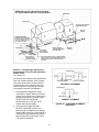
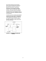
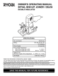
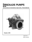
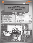
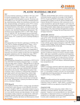
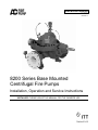
Instruction Manual
AC2675
REVISION A
8200 Series Base Mounted
Centrifugal Fire Pumps
Installation, Operation and Service Instructions
INSTALLER: PLEASE LEAVE THIS MANUAL FOR THE OWNER’S USE.
1
TABLE OF CONTENTS
DESCRIPTION......................................................3
MAINTENANCE TIME TABLE........................... 19
OPERATIONAL LIMITS .......................................3
TROUBLE SHOOTING ...................................... 20
MAXIMUM WORKING PRESSURE .....................3
CHANGING ROTATION .................................... 23
SEAL OPERATING LIMITS .................................3
PACKING ......................................................3
SERVICE INSTRUCTIONS ................................ 24
DISASSEMBLY AND REASSEMBLY
PROCEDURES ................................... 24
DISMANTLING (PUMP WITH PACKING) .. 24
ASSEMBLY (PUMP WITH PACKING) ....... 27
PUMP IDENTIFICATION ......................................3
SAFETY INSTRUCTIONS ....................................4
ADDITIONAL SAFETY REQUIREMENTS:...4
APPENDIX “A” ENGINEERING DATA ............. 30
APPENDIX “B” .................................................. 31
EXPLODED VIEW – 8200 SERIES FIRE
PUMP .................................................. 31
REPLACEMENT PARTS LIST ................... 32
INSTRUCTIONS FOR ORDERING PARTS33
ADDITIONAL SAFETY REQUIREMENTS:..........5
ELECTRICAL SAFETY: ................................5
THERMAL SAFETY: .....................................5
MECHANICAL SAFETY:...............................5
INSTALLATION ....................................................6
PUMP LOCATION.........................................6
RECEIVING PUMP .......................................6
TEMPORARY STORAGE .............................7
LOCATION ....................................................7
FOUNDATION...............................................7
BASE PLATE SETTING (BEFORE PIPING) 8
GROUTING PROCEDURE ...........................8
SEE ANSI/OSHA COUPLER GUARD
REMOVAL/INSTALLATION ..................8
ALIGNMENT PROCEDURE .........................8
ANSI/OSHA COUPLER GUARD
REMOVAL/INSTALLATION ..................9
DOWELING .................................................11
SUCTION AND DISCHARGE PIPING ........11
STUFFING BOX LUBRICATION.................14
PACKING ....................................................14
APPENDIX “C” FIELD TEST REPORT ............ 34
USEFUL FORMULAS................................. 35
NOTE
The information contained in this book is intended
to assist operating personnel by providing
information on the characteristics of the purchased
equipment.
It does not relieve the user of their responsibility of
using accepted engineering practices in the
installation, operation, and maintenance of this
equipment.
Any further questions, contact ITT A-C Pump,
(847) 966-3700.
OPERATION .......................................................16
PRE-START CHECKS ................................16
PRIMING .....................................................16
STARTING ..................................................16
OPERATING CHECKS ...............................16
FREEZING PROTECTION..........................17
FIELD TESTING..........................................17
MAINTENANCE..................................................17
GENERAL MAINTENANCE ........................17
MAINTENANCE OF PUMP DUE TO FLOOD
DAMAGE .............................................17
BEARING LUBRICATION – GREASE ........18
PACKING SEAL ..........................................18
CLEANING WITHOUT DISMANTLING
PUMP ..................................................18
2
DESCRIPTION
PUMP IDENTIFICATION
The 8200 Series Centrifugal Fire Pumps are
framed mounted pumps which feature – high
efficiency, rugged construction, compact
design, foot mounted volute and regreasable
bearings. These features, along with the
horizontal split case, make installation,
operation and service easy to perform.
There are two identification plates on each
pump. The pump rating plate gives
identification and rating information. Figure 1
shows an example of a typical Rating Plate.
Permanent records for this pump are
referenced by the Serial Number and it must,
therefore, be used with all correspondence to
order all spare parts and replacement parts.
The fourth digit indicates the specific pump
on orders for more than one pump. For
example, if an order called for six pumps, all
pumps would have the same first three sets
of digits and the last digit will change to
identify each of the six. (e.g. 03-123456-0101, 03-123456-01-02, etc.)
OPERATIONAL LIMITS
Unless special provisions have been made
for your pump by ITT A-C Fire Pump
Systems, the operational limits for 8200
Series Centrifugal Fire Pumps are as follows:
MAXIMUM WORKING PRESSURE
The frame plate, shown below in Figure 2,
gives information concerning the bearings
and their lubrication. The inboard and
outboard bearing numbers refer to the
bearing manufacturer’s numbers.
Listed on pump nameplate.
SEAL OPERATING LIMITS
PACKING
PH Limitations 7-9; Temperature Range 0 to
+200°F
For use on open or closed systems which
require a large amount of makeup water, as
well as systems which are subjected to widely
varying chemical conditions and solids
buildup.
FIGURE 1 – RATING PLATE
FIGURE 2 – FRAME PLATE
3
ADDITIONAL SAFETY REQUIREMENTS:
1. Electrical connections to be made by
qualified Electrician in accordance with all
national, state and local codes.
SAFETY INSTRUCTIONS
SAFETY INSTRUCTIONS
This safety alert symbol will be used in this
manual and on the pump safety instruction decals
to draw attention to safety related instructions.
When used the safety alert symbol means
ATTENTION! BECOME ALERT! YOUR SAFETY
IS INVOLVED! FAILURE TO FOLLOW THE
INSTRUCTIONS MAY RESULT IN A SAFETY
HAZARD.
2. Motor must have properly sized starter
with properly sized heaters to provide
overload and undervoltage protection.
3. If pump, motor or piping are operating at
extremely high or low temperatures,
guarding or insulation is required.
4. The maximum working pressure of the
pump is listed on the pump nameplate, do
not exceed this pressure.
Your 8200 Series Centrifugal Fire Pump should
have the following safety instruction decals
displayed. If the decals are missing or illegible
contact your local ITT A-C Fire Pump Systems
representative for a replacement.
WARNING
ROTATING COMPONENTS
DISCONNECT AND LOCKOUT
POWER BEFORE SERVICING.
DO NOT OPERATE WITHOUT
ALL GUARDS IN PLACE.
CONSULT INSTALLATION
AND SERVICE INSTRUCTION
SHEET BEFORE OPERATING
OR SERVICING.
FAILURE TO FOLLOW
INSTRUCTIONS COULD
RESULT IN INJURY
OR DEATH.
WARNING
EYEBOLTS OR LIFTING
LUGS IF PROVIDED ARE
FOR LIFTING ONLY THE
COMPONENTS TO WHICH
THEY ARE ATTACHED.
FAILURE TO FOLLOW
INSTRUCTIONS COULD
RESULT IN INJURY
OR DEATH.
CAUTION
COUPLER ALIGNMENT IS
REQUIRED! LEVEL AND
GROUT PUMP BEFORE USE!
CHECK ALIGNMENT BEFORE
GROUTING, AFTER SYSTEM
IS FILLED, AFTER SERVICING
PUMP, AND AS REQUIRED.
CONSULT THE SERVICE
INSTRUCTIONS FOR DETAILS.
FAILURE TO FOLLOW THESE
INSTRUCTIONS COULD
RESULT IN INJURY OR
PROPERTY DAMAGE.
CAUTION
DO NOT RUN PUMP DRY,
SEAL DAMAGE MAY OCCUR.
INSPECT PUMP SEAL
REGULARKY FOR LEAKS,
REPLACE AS REQUIRED.
FOR LUBRICATION
REQUIREMENTS, CONSULT
SERVICE INSTRUCTIONS.
FAILURE TO FOLLOW
INSTRUCTIONS COULD
RESULT IN INJURY OR
PROPERTY DAMAGE.
FIGURE 3 - SAFETY INSTRUCTION DECALS
4
ADDITIONAL SAFETY REQUIREMENTS:
ELECTRICAL SAFETY:
MECHANICAL SAFETY:
WARNING: Electrical Shock Hazard
Electrical connections to be made by a
qualified electrician in accordance with all
applicable codes, ordinances, and good practices.
Failure to follow these instructions could result in
serious personal injury or death, and property
damage.
WARNING: Unexpected Startup Hazard
Disconnect and lockout power before
servicing. Failure to follow these instructions could
result in serious personal injury or death, and
property damage.
WARNING: Excessive System Pressure
Hazard
The maximum working pressure of the pump is
listed on the nameplate, do not exceed this
pressure. Failure to follow these instructions could
result in serious personal injury or death, and
property damage.
WARNING: Electrical Overload Hazard
Three phase motors must have properly
sized heaters to provide overload and under
voltage protection. Single-phase motors have
built-in overload protectors. Failure to follow these
instructions could result in serious personal injury
or death, and property damage.
WARNING: Excessive Pressure Hazard
WARNING
Volumetric Expansion
The heating of water and other fluids causes
volumetric expansion. The associated forces may
cause failure of system components and release
of high temperature fluids. Installing properly sized
and located compression tanks and pressure relief
valves will prevent this. Failure to follow these
instructions could result in serious personal injury
or death, and property damage.
THERMAL SAFETY:
WARNING: Extreme Temperature
Hazard
If pump, motor, or piping is operating at extremely
high or low temperature, guarding or insulation is
required. Failure to follow these instructions could
result in serious personal injury or death, and
property damage.
CAUTION
WARNING
5
INSTALLATION
PUMP LOCATION
Locate the pump so there is sufficient room
for inspection, maintenance and service. If
the use of a hoist or tackle is needed, allow
ample head room.
NYLON SLING,
CHAIN OR WIRE
ROPE
WARNING: Falling Objects Hazard
Eyebolts or lifting lugs, if provided, are for
lifting only the components to which they are
attached. Failure to follow these instructions could
result in serious personal injury or death, or
property damage.
CHOKER
HITCH
AROUND
BEARING
FRAME
If lifting base pump is required, use a nylon
string, chain, or wire rope, hitch around both
bearing supports. If lifting of the entire pump is
required, do so with slings placed under the
base rails as shown.
FIGURE 4
Care must be taken to size equipment for
unbalanced loads which may exist if the
motor is not mounted on the base at the time
of lifting. Motor may or may not be mounted
at the factory.
If the pump is not on a closed system, it
should be placed as near as possible to the
source of the liquid supply, and located to
permit installation with the fewest number of
bends or elbows in the suction pipe.
Pump, base, and driver assemblies where the
base length exceeds 100 inches may not be
safe to lift as a complete assembly. Damage to
the baseplate may occur. If the driver has
been mounted on the baseplate at the factory,
it is safe to lift the entire assembly. If the driver
has not been mounted at the factory, and the
overall baseplate length exceeds 100 inches,
do not lift the entire assembly consisting of
pump, base, and driver. Instead, lift the pump
and baseplate to its final location without the
driver. Then mount the driver.
The installation must be evaluated to
determine that the Net Positive Suction Head
Available (NPSHA) meets or exceeds the Net
Positive Suction Head Required (NPSHR), as
stated by the pump performance curve. See
page 11 for more details on proper suction
piping installation.
RECEIVING PUMP
Check pump for shortages and damage
immediately upon arrival. (An absolute must.)
Prompt reporting to the carrier’s agent with
notations made on the freight bill, will
expedite satisfactory adjustment by the
carrier.
The best pump location for sound and
vibration ab-sorption is on a concrete floor
with subsoil underneath. If the pump location
is overhead, special precautions should be
undertaken to reduce possible sound
transmission. Consult a sound specialist.
Pumps and drivers normally are shipped from
the factory mounted and painted with primer
and one finish coat. Couplings may be either
completely assembled or have the coupling
hubs mounted on the shafts and the
connecting members removed. When the
connecting members are removed, they will
be packaged in a separate container and
shipped with the pump or attached to the
base plate.
Shafts are in alignment when the unit is
shipped; however, due to shipping, the
pumps may arrive mis-aligned and, therefore,
alignment must be established during
6
collect should be blown out with compressed
air.
installation. ITT AC Fire Pump Systems has
determined that proper and correct alignment
can only be made by accepted erection
practices. Refer to the following paragraphs
on “Foundation,” “Base Plate Setting,”
“Grouting Procedure,” “Alignment Procedure”
and “Doweling.”
Make sure there is a suitable power source
available for the pump driver. If motor driven,
electrical characteristics should be identical to
those shown on motor data plate.
FOUNDATION
A substantial foundation and footing should
be built to suit local conditions. The
foundation must be substantial enough to
absorb vibration. (Hydraulic Institute
Standards recommends the foundation weigh
at least five (5) times the weight of the pump
unit.) It must form a permanent and rigid
support for the baseplate. This is important in
maintaining the alignment of the flexibly
coupled unit.
TEMPORARY STORAGE
If the pump is not to be installed and operated
soon after arrival, store it in a clean, dry place
having slow, moderate changes in ambient
temperature. Rotate the shaft periodically to
coat the bearings with lubricant and to retard
oxidation, corrosion, and to reduce the
possibility of false brinelling of the bearings.
LOCATION
The pump should be installed as near the
suction supply as possible, but no less than
five suction diameters (refer to page 11,
suction and discharge piping section) with the
shortest and most direct suction pipe
practical. The total dynamic suction lift (static
lift plus friction losses in suction line) should
not exceed the limits for which the pump was
sold.
The foundation should be poured without
interruption to within 1/2 to 1-1/2 inches of the
finished height. The top surface of the
foundation should be well scored and
grooved before the concrete sets; this
provides a bonding surface for the grout.
Foundation bolts should be set in concrete as
shown in Figure 5. An optional 4-inch long
tube around the bolts at the top of the
concrete will allow some flexibility in bolt
alignment to match the holes in the base
plate. Allow enough bolt length for grout,
shims, lower base plate flange, nuts and
washers. The foundation should be allowed
to cure for several days before the base plate
is shimmed and grouted.
The pump must be primed before starting.
Whenever possible, the pump should be
located below the fluid level to facilitate
priming and assure a steady flow of liquid.
This condition provides a positive suction
head on the pump. It is also possible to prime
the pump by pressurizing the suction vessel.
When installing the pump, consider its
location in relation to the system to assure
that sufficient Net Positive Suction Head
(NPSH) at pump suction is provided.
Available NPSH must always equal or exceed
the required NPSH of the pump.
PIPE SLEEVE
The pump should be installed with sufficient
accessibility for inspection and maintenance.
A clear space with ample head room should
be allowed for the use of an overhead crane
or hoist sufficiently strong to lift the unit.
FOUNDATION
BOLT
(OPTIONAL)
WASHER
NOTE: Allow sufficient space to be able to
dismantle pump without disturbing the pump
inlet and discharge piping.
BUILT-UP CONCRETE
FOUNDATION
FIGURE 5 – FOUNDATION
Select a dry place above the floor level
wherever possible. Take care to prevent
pump from freezing during cold weather when
not in operation. Should the possibility of
freezing exist during a shut-down period, the
pump should be completely drained, and all
passages and pockets where liquid might
7
operator). Final alignment procedures are
covered under “Alignment Procedures.”
BASE PLATE SETTING (BEFORE PIPING)
NOTE: This procedure assumes that a
concrete foundation has been prepared with
anchor or hold down bolts extending up ready
to receive unit. It must be understood that
pump and motor have been mounted and
rough aligned at the factory. If motor is to be
field mounted, consult factory for
recommendations. ITT AC Fire Pump
Systems cannot assume responsibility for
final alignment.
ALLOW 1" FOR
SHIMS. PLACE ON
BOTH SIDES OF
ANCHOR BOLTS.
NOTE:
TO KEEP SHIMS IN
PLACE ALLOW GROUT
TO FLOW AROUND
HOLD DOWN LUGS.
e. Check to make sure the piping can be
aligned to the pump flanges without
placing pipe strain on either flange.
f. Grout in base plate completely (See
“Grouting Procedure”) and allow grout to
dry thoroughly before attaching piping to
pump. (24 hours is sufficient time with
approved grouting procedure.)
GROUTING PROCEDURE
Grout compensates for uneven foundation,
distributes weight of unit, and prevents
shifting. Use an approved, non-shrinking
grout, after setting and leveling unit (See
Figure 6).
GROUT ONLY TO
TOP OF BASE RAIL.
PUMP BASE
RAIL
a. Build strong form around the foundation to
contain grout.
b. Soak top of concrete foundation
thoroughly, then remove surface water.
GROUT
APPROX. 1" GAP
c. Base plate should be completely filled with
grout.
CONCRETE
FOUNDATION
d. After the grout has thoroughly hardened,
check the foundation bolts and tighten if
necessary.
LEVELING OF PUMP BASE
ON CONCRETE FOUNDATION.
FIGURE 6 – SETTING BASE PLATE AND
GROUTING
e. Check the alignment after the foundation
bolts are tightened.
a. Use blocks and shims under base for
support at anchor bolts and midway
between bolts, to position base
approximately 1" above the concrete
foundation, with studs extending through
holes in the base plate.
f. Approximately 14 days after the grout has
been poured or when the grout has
thoroughly dried, apply an oil base paint to
the exposed edges of the grout to prevent
air and moisture from coming in contact
with the grout.
b. By adding or removing shims under the
base, level and plumb the pump shaft and
flanges. The base plate does not have to
be level.
SEE ANSI/OSHA COUPLER GUARD
REMOVAL/INSTALLATION
(SEE BELOW)
c. Draw anchor nuts tight against base, and
observe pump and motor shafts or
coupling hubs for alignment. (Temporarily
remove coupling guard for checking
alignment.)
ALIGNMENT PROCEDURE
NOTE: A flexible coupling will only
compensate for small amounts of
misalignment. Permissible misalignment will
vary with the make of coupling. Consult
coupling manufacturer’s data when in doubt.
d. If alignment needs improvement, add
shims or wedges at appropriate positions
under base, so that retightening of anchor
nuts will shift shafts into closer alignment.
Repeat this procedure until a reasonable
alignment is reached.
Allowances are to be made for thermal
expansion during cold alignment, so that the
coupling will be aligned at operating
temperature. In all cases, a coupling must be
in alignment for continuous operation. Even
though the coupling may be lubricated,
misalignment causes excessive wear,
NOTE: Reasonable alignment is defined as
that which is mutually agreed upon by pump
contractor and the accepting facility (final
8
vibration, and bearing loads that result in
premature bearing failure and ultimate seizing
of the pump. Misalignment can be angular,
parallel, or a combination of these, and in the
horizontal and vertical planes. Final alignment
should be made by moving and shimming the
motor on the base plate, until the coupling
hubs are within the recommended tolerances
measured in total run-out. All measurements
should be taken with the pump and motor foot
bolts tightened. The shaft of sleeve bearing
motors should be in the center of its
mechanical float.
c. Remove the capscrew that holds the inner
guard to the support bracket.
d. Spread the inner guard and pull it over the
coupler.
Installation
a. Check coupler alignment before
proceeding. Correct if necessary.
b. Spread the inner guard and place it over
the coupler.
c. With the inner guard straddling the
support bracket, install a capscrew
through the hole (or slot) in the support
bracket and guard located closest to the
pump. Do not tighten the capscrew.
NOTE: Proper alignment is essential for
correct pump operation. This should be
performed after base plate has been properly
set and grout has dried thoroughly according
to instructions. Final alignment should be
made by shimming driver only. Alignment
should be made at operating temperatures.
d. Spread the outer guard and place it over
the inner guard.
e. Install the outer guard capscrews by
following the step stated below which
pertains to your particular pump:
WARNING: Unexpected Start-up Hazard
Disconnect and lock out power before
servicing. Failure to follow these instructions could
result in serious personal injury or death and
property damage.
i. For pumps with a motor saddle support
bracket: Ensure the outer guard is
straddling the support arm, and install
but do not tighten the two remaining
capscrews.
ANSI/OSHA COUPLER GUARD
REMOVAL/INSTALLATION
ii. For pumps without a motor saddle
support bracket: Insert the spacer
washer between the holes located
closest to the motor in the outer guard,
and install, but do not tighten, the two
remaining capscrews.
WARNING: Unexpected Start-up Hazard
Disconnect and lock out power before
servicing. Failure to follow these instructions could
result in serious personal injury or death and
property damage.
NOTE: Do not spread the inner and outer
guards more than necessary for guard
removal or installation. Over spreading the
guards may alter their fit and appearance.
f. Position the outer guard so it is centered
around the shaft, and so there is less than
a 1/4" of the motor shaft exposed. On
guards that utilize a slotted support
bracket, the inner guard will have to be
positioned so there is only a 1/4" of the
pump shaft exposed.
Removal
a. Remove the two capscrews that hold the
outer (motor side) coupler guard to the
support bracket(s).
g. Holding the guard in this position, tighten
the three capscrews.
b. Spread the outer guard and pull it off the
inner guard.
9
ANSI/OSHA Coupling Guard Exploded View
For Typical 8200 Series Fire Pump Installation
INNER GUARD
OUTER GUARD
ATTACH SUPPORT BRACKET
TO BEARING HOUSING
SUPPORT
BRACKET
LOCATE SUPPORT ARM
BETWEEN OUTER GUARD ENDS.
ALIGN THE ARM WITH HOLES IN
THE OUTER GUARD AND HOLES
IN THE SADDLE BRACKET.
NUT
BRACKET SUPPORT
ATTACHED INSIDE HERE
IN LINE WITH BOLT
LOCKWASHER
CAPSCREW
BRACKET
SUPPORT
FLAT WASHER
SPACER WASHER
MOTOR SADDLE
BRACKET ATTACH
TO MOTOR SADDLE
THIS OPTION USED IN PLACE OF SPACER WHERE
OVERALL LENGTH OF GUARD EXCEEDS 12 INCHES
OR GUARD WITH IS OVER 10 INCHES ACROSS
THE FLATS.
Method 1 – Straight Edge Alignment for
Standard Sleeve Type Coupler with Black
Rubber Insert
(See Figure 7A)
STRAIGHT EDGE
Proceed with this method only if satisfied that
face and outside diameters of the coupling
halves are square and concentric with the
coupling borers. If this condition does not
exist or elastomeric couplings do not make
this method convenient, use Method 2.
FEELER GAGE
ANGULAR ALIGNMENT
PARALLEL ALIGNMENT
INCORRECT ALIGNMENT
STRAIGHT EDGE
1. Check angular misalignment using a
micrometer or caliper. Measure from the
outside of one flange to the outside of the
opposite flange at four points 90° apart.
DO NOT ROTATE COUPLER.
Misalignment up to 1/64" per inch of
coupler radius is permissible.
FEELER GAGE
CORRECT ALIGNMENT
FIGURE 7A – CHECKING ALIGNMENT
(METHOD 1)
2. At four points 90° apart (DO NOT
ROTATE COUPLER), measure the
parallel coupler misalignment by laying a
straight edge across one coupler half and
measuring the gap between the straight
edge and opposite coupler half. Up to a
1/64" gap is permissible.
10
Final Alignment
Final alignment cannot be accomplished until
the pump has been operated initially for a
sufficient length of time to attain operating
temperature. When normal operating
temperature has been attained, secure the
pump to re-check alignment and compensate
for temperature accordingly. See Alignment
Section.
Method 2 – For Orange Hytrel Insert, 3500
RPM Operation, or All Other Coupler
Types
(See Figure 7B)
a. Make sure each hub is secured to its
respective shaft and that all connecting
and/or spacing elements are removed at
this time.
b. The gap between the coupling hubs is set
by the manufacturer before the units are
shipped. However, this dimension should
be checked. (Refer to the coupling
manufacturer’s specifications supplied
with the unit.)
WARNING: Rotating Components
Hazard
Do not operate pump without all guards in place.
Failure to follow these instructions could result in
serious personal injury or death and property
damage.
c. Scribe index lines on coupling halves as
shown in Figure 7B.
OPTIONAL Alignment Procedure
If desired, the pump and motor feet can be
doweled to the base after final alignment is
complete. This should not be done until the
unit has been run for a sufficient length of
time and alignment is within the tolerance.
See Doweling Section.
d. Mount dial indicator on one hub as shown
for parallel alignment. Set dial to zero.
e. Turn both coupling halves so that index
lines remain matched. Observe dial
reading to see whether driver needs
adjustment (See paragraph i below).
f. Mount dial indicator on one hub as shown
for angular alignment. Set dial to zero.
CAUTION: Extreme Temperature and/or
Flying Debris Hazard
Eye protection and gloves required. Failure to
follow these instructions could result in property
damage and/or moderate personal injury.
g. Turn both coupling halves so that index
lines remain matched. Observe dial
reading to see whether driver needs
adjustment (See paragraph i below).
NOTE: Pump may have been doweled to
base at factory.
h. Assemble coupling. Tighten all bolts and
set screw(s). It may be necessary to
repeat steps c through f for a final check.
DOWELING
Dowel the pump and driving unit as follows:
i. For single element couplings, a
satisfactory parallel misalignment is
.004"T.I.R., while a satisfactory angular
misalignment is .004"T.I.R. per inch of
radius R (See Figure 7B).
PARALLEL
ALIGNMENT
a. Drill holes through diagonally opposite feet
and into the base. Holes must be of a
diameter 1/64 inch less than the diameter
of the dowel pins. Clean out the chips.
b. Ream the holes in feet and base to the
proper diameter for the pins (light push fit).
Clean out the chips.
DIAL
INDICATOR
c. Insert pins to be approximately flush with
feet.
INDEX LINE
SUCTION AND DISCHARGE PIPING
RESILIENT
SEPARATOR
ANGULAR
ALIGNMENT
General
When installing the pump piping, be sure to
observe the following precautions:
DIAL
INDICATOR
Piping should always be run to the pump.
Do not move pump to pipe. This could make
final alignment impossible.
FIGURE 7B – CHECKING ALIGNMENT
(METHOD 2)
Both the suction and discharge piping should
be supported independently near the pump
11
and properly aligned, so that no strain is
transmitted to the pump when the flange bolts
are tightened. Use pipe hangers or other
supports at necessary intervals to provide
support. When expansion joints are used in
the piping system, they must be installed
beyond the piping supports closest to the
pump. Tie bolts should be used with
expansion joints to prevent pipe strain. Do not
install expansion joints next to the pump or in
any way that would cause a strain on the
pump resulting from system pressure
changes. It is usually advisable to increase
the size of both suction and discharge pipes
at the pump connections to decrease the loss
of head from friction.
SUCTION PIPE INSTALLED WITH A
GRADUAL RISE TO PUMP
CHECK VALVE
GATE VALVE
INCREASER
LEVEL
CORRECT
CENTER LINE
OF PIPE
AIR POCKET
INCORRECT
AIR POCKET
Install piping as straight as possible, avoiding
unnecessary bends. Where necessary, use
45-degree or long sweep 90-degree fitting to
decrease friction losses.
INCORRECT
Make sure that all piping joints are air-tight.
AIR POCKET
Where flanged joints are used, assure that
inside diameters match properly.
INCORRECT
Remove burrs and sharp edges when making
up joints.
Do not “spring” piping when making any
connections.
GRADUAL RISE
TO PUMP
Provide for pipe expansion when hot fluids are
to be pumped.
NO AIR
POCKETS
CORRECT
Suction Piping
When installing the suction piping, observe
the following precautions. Figure 8 shows
some correct and incorrect suction piping
arrangements.
NO AIR
POCKETS
GRADUAL RISE
TO PUMP
ECCENTRIC
REDUCER
CORRECT
The sizing and installation of the suction
piping is extremely important. It must be
selected and installed so that pressure losses
are minimized and sufficient liquid will flow
into the pump when started and operated.
Many NPSH (Net Positive Suction Head)
problems can be attributed directly to
improper suction piping systems.
DISTANCE PLUS
ECCENTRIC REDUCER
STRAIGNTENS FLOW
Friction losses caused by undersized suction
piping can increase the fluid’s velocity into the
pump. As recommended by the Hydraulic
Institute Standard ANSI/HI 1.1-1.5-1994,
suction pipe velocity should not exceed the
velocity in the pump suction nozzle. In some
situations pipe velocity may need to be
further reduced to satisfy pump NPSH
requirements and to control suction line
losses. Pipe friction can be reduced by using
pipes that are one to two sizes larger than the
pump suction nozzle in order to maintain pipe
velocities less than 5 feet/second.
CORRECT
PATH OF WATER
INCORRECT
FIGURE 8 – SUCTION INSTALLATIONS
(PIPING SUPPORTS NOT SHOWN)
12
spring type, sized to avoid excessive
friction in the suction line. (Under all other
conditions, a check valve, if used, should
be installed in the discharge line.) (See
“Valves in Discharge Piping”)
Suction piping should be short in length, as
direct as possible, and never smaller in
diameter than the pump suction opening. A
minimum of ten (10) pipe diameters between
any elbow or tee and the pump should be
allowed. If a long suction pipe is required, it
should be one or two sizes larger than the
suction opening, depending on its length.
b. When foot valves are used, or where there
are other possibilities of “water hammer,”
close the discharge valve slowly before
shutting down the pump.
CAUTION:
An elbow should not be used directly
before the suction of a double suction pump if its
plane is parallel to the pump shaft. This can cause
an excessive axial load or NPSH problems in the
pump due to an uneven flow distribution. If there is
no other choice, the elbow should have
straightening vanes to help evenly distribute the
flow. Failure to follow these instructions could
result in injury or property damage.
c. Where two or more pumps are connected
to the same suction line, install gate
valves so that any pump can be isolated
from the line. Gate valves should be
installed on the suction side of all pumps
with a positive pressure for maintenance
purposes. Install gate valves with stems
horizontal to avoid air pockets. Globe
valves should not be used, particularly
where NPSH is critical.
Eccentric reducers should be limited to one
pipe size reduction each to avoid excessive
turbulence and noise. They should be of the
conical type. Contour reducers are not
recommended.
d. The pump must never be throttled by the
use of a valve on the suction side of the
pump. Suction valves should be used only
to isolate the pump or maintenance
purposes, and should always be installed
in positions to avoid air pockets.
When operating on a suction lift, the suction
pipe should slope upward to the pump
nozzle. A horizontal suction line must have a
gradual rise to the pump. Any high point in
the pipe can become filled with air and
prevent proper operation of the pump. When
reducing the piping to the suction opening
diameter, use an eccentric reducer with the
eccentric side down to avoid air pockets.
e. A pump drain valve should be installed in
the suction piping between the isolation
valve and the pump.
Discharge Piping
If the discharge piping is short, the pipe
diameter can be the same as the discharge
opening. If the piping is long, pipe diameter
should be one or two sizes larger than the
discharge opening. On long horizontal runs, it
is desirable to maintain as even a grade as
possible. Avoid high spots, such as loops,
which will collect air and throttle the system or
lead to erratic pumping.
NOTE: When operating on suction lift never
use a concentric reducer in a horizontal
suction line, as it tends to form an air pocket
in the top of the re-ducer and the pipe.
To facilitate cleaning pump liquid passage
without dismantling pump, a short section of
pipe (Dutchman or spool piece) so designed
that it can be readily dropped out of the line
can be installed adjacent to the suction
flange. With this arrangement, any matter
clogging the impeller is accessible by
removing the nozzle (or pipe section).
Valves in Discharge Piping
A slow closing check valve and an isolating
gate valve should be installed in the
discharge line. The check valve (triple duty
valve), placed between pump and gate valve,
protects the pump from excessive back
pressure, and prevents liquid from running
back through the pump in case of power
failure. The gate valve is used in priming and
starting, and when shutting the pump down.
Valves in Suction Piping
When installing valves in the suction piping,
observe the following precautions:
a. If the pump is operating under static
suction lift conditions, a foot valve may be
installed in the suction line to avoid the
necessity of priming each time the pump
is started. This valve should be of the
flapper type, rather than the multiple
13
lubricate packing. Only when all of the
following conditions prevail, can this be done:
Pressure Gauges
Properly sized pressure gauges should be
installed in both the suction and discharge
nozzles in the gauge taps provided. The
gauges will enable the operator to easily
observe the operation of the pump, and also
determine if the pump is operating in
conformance with the performance curve. If
cavitation, vapor binding, or other unstable
operation should occur, widely fluctuating
discharge pressure will be noted.
1. Liquid is clean, free from sediment and
chemical precipitation and is compatible
with seal materials.
2. Temperature is above 32°F and below
160°F.
3. Suction pressure is below 75 psig.
4. Lubrication (pumped liquid) has lubricating
qualities.
Pump Insulation
On chilled water applications most pumps are
insulated. As part of this practice, the pump
bearing housings should not be insulated
since this would tend to “trap” heat inside the
housing. This could lead to increased bearing
temperatures and premature bearing failures.
5. Liquid is non-toxic and non-volatile.
When the liquid being pumped contains
solids or is otherwise not compatible with
packing materials, an outside supply of seal
liquid should be furnished. In general,
external-injection liquid (from an outside
source) is required when any of the above
conditions cannot be met.
STUFFING BOX LUBRICATION
Contaminants in the pumped liquid must not
enter the stuffing box. These contaminants
may cause severe abrasion or corrosion of
the shaft, or shaft sleeve, and rapid packing
deterioration; they can even plug the stuffing
box flushing and lubrication system. The
stuffing box must be supplied at all times with
a source of clean, clear liquid to flush and
lubricate the packing or seal. It is important to
establish the optimum flushing pressure that
will keep contaminants from the stuffing box
cavity. If this pressure is too low, fluid being
pumped may enter the stuffing box. If the
pressure is too high, excessive packing wear
may result; and extreme heat may develop in
the shaft causing higher bearing
temperatures. The most desirable condition,
therefore, is to use a seal water pressure 1520 psig above the maximum stuffing box
pressure.
The standard stuffing box consists of rings of
packing (see assembly section for number of
rings), a seal cage, a bushing and a gland. A
shaft sleeve which extends through the box
and under the gland is provided to protect the
shaft.
A tapped hole is supplied in the stuffing box
directly over the seal cage to introduce a
clean, clear sealing medium. The stuffing box
must, at all times, be supplied with sealing
liquid at a high enough pressure to keep the
box free from foreign matter, which would
quickly destroy the packing and score the
shaft sleeve.
Only a sufficient volume of sealing liquid to
create a definite direction of flow from the
stuffing box inward to the pump casing is
required, but the pressure is important. Apply
seal water at a rate of approximately .25
GPM at a pressure approximately 15 to 20
psig above the suction pressure.
(Approximately one (1) drop per second.)
PACKING
Standard pumps are normally packed before
shipment. If the pump is installed within 60
days after shipment, the packing will be in
good condition with a sufficient supply of
lubrication. If the pump is stored for a longer
period, it may be necessary to repack the
stuffing box. In all cases, however, inspect
the packing before the pump is started.
One recommended method to minimize error
in regulating flushing water is a “Controlled
Pressure System” (Figure 9). It is important to
set the pressure reducing valve adjusted to a
value slightly exceeding the maximum
stuffing box operating pressure (assuming it
is reasonably constant). A flow indicating
device will detect a failing of the bottom
packing rings allowing leakage in the pump.
NOTE: Packing adjustment is covered in the
MAINTENANCE section of this manual.
On some applications, it is possible to use
internal liquid lubrication (pumped liquid) to
External sealing liquid should be adjusted to
the point where the packing runs only slightly
warm, with a very slow drip from the stuffing
14
box. Excess pressure from an external
source can be very destructive to packing.
More pressure is required, however, for
abrasive slurries than for clear liquids.
Examination of the leakage will indicate
whether to increase or decrease external
pressure. If slurry is present in the leakage,
increase the pressure until only clear liquid
drips from the box. If the drippage is corrosive
or harmful to personnel, it should be collected
and piped away.
A common error is to open the external piping
valve wide and then control the drippage by
tightening the packing gland. A combination
of both adjustments is essential to arrive at
the optimum condition. The life of packing
and sleeve depends on careful control more
than any other factor.
FLOWMETER
PRESSURE
GAUGE
PRESSURE
REDUCING
VALVE
STUFFING BOX
FIGURE 9 – CONTROLLED PRESSURE
SYSTEM
15
OPERATION
WARNING: Rotating Components
Hazard
Do not operate pump without all guards in place.
Failure to follow these instructions could result in
serious personal injury or death and property
damage.
WARNING: Unexpected Startup Hazard
Disconnect and lockout power before
servicing. Failure to follow these instructions could
result in serious personal injury or death, or
property damage.
WARNING: Electrical Shock Hazard
Electrical connections to be made by a
qualified electrician in accordance with all
applicable codes, ordinances, and good practices.
Failure to follow these instructions could result in
serious personal injury or death, or property
damage.
CAUTION: Seal Damage Hazard
Do not run pump dry, seal damage may
occur. Failure to follow these instructions could
result in property damage and/or moderate
personal injury.
PRIMING
If the pump is installed with a positive head
on the suction, it can be primed by opening
the suction and vent valve and allowing the
liquid to enter the casing.
PRE-START CHECKS
Before initial start of the pump, make the
following inspections:
a. Check alignment between pump and
motor.
If the pump is installed with a suction lift,
priming must be done by other methods such
as foot valves, ejectors, or by manually filling
the casing and suction line.
b. Check all connections to motor and
starting device with wiring diagram. Check
voltage, phase, and frequency on motor
nameplate with line circuit.
WARNING: Rotating Components
Hazard
Do not operate pump without all guards in place.
Failure to follow these instructions could result in
serious personal injury or death and property
damage.
c. Check suction and discharge piping and
pressure gauges for proper operation.
d. Check impeller adjustment, see specific
section for proper adjustment.
e. Turn rotating element by hand to assure
that it rotates freely.
STARTING
a. Close drain valves and valve in discharge
line.
f. Check driver lubrication.
g. Assure that pump bearings are properly
lubricated.
b. Open fully all valves in the suction line.
h. Assure that coupling is properly lubricated,
if required.
NOTE: If the pump does not prime properly,
or loses prime during start-up, it should be
shutdown and the condition corrected before
the procedure is repeated.
c. Prime the pump.
i. Assure that pump is full of liquid (See
Priming) and all valves are properly set
and operational, with the discharge valve
closed, and the suction valve open.
d. When the pump is operating at full speed,
open the discharge valve slowly. This
should be done promptly after start-up to
prevent damage to pump by operating at
zero flow.
j. Check rotation. Be sure that the drive
operates in the direction indicated by the
arrow on the pump casing as serious
damage can result if the pump is operated
with incorrect rotation. Check rotation
each time the motor leads have been
disconnected.
OPERATING CHECKS
a. Check the pump and piping to assure that
there are no leaks.
16
b. Check and record pressure gauge
readings for future reference.
CAUTION: Bearing/Seal Damage Hazard
Do not let heated pump temperature rise
above 150°F. Failure to follow these instructions
could result in property damage and/or moderate
personal injury.
c. Check and record voltage, amperage per
phase, and kw if an indicating wattmeter is
available.
d. Check bearings for lubrication and
temperature. Normal temperature is 180°
maximum.
FIELD TESTING
A typical performance curve for a specific
pump can be obtained from ITT A-C Fire
Pump Systems. This can be used in
conjunction with a field test, if one is required.
All ITT A-C Fire Pump Systems tests and
curves are based on the Hydraulic Institute
Standards. Any field test must be conducted
according to these Standards.
e. Make all pump output adjustments with
the discharge line.
CAUTION: Cavitation Damage Hazard
Do not throttle the suction line to adjust the
pump output. Failure to follow these instructions
could result in property damage and/or moderate
personal injury.
Unless otherwise specifically agreed, all
capacity, head, and efficiencies are based on
shop tests when handling clear, cold, fresh
water at a temperature not over 85°F.
FREEZING PROTECTION
Pumps that are shut down during freezing
conditions should be protected by one of the
following methods.
Appendix “C” (Pages 34-35) contains a field
test report sheet and some useful equations
which can be used when conducting a field
test.
a. Drain the pump; remove all liquids from
the casing.
b. Keep fluid moving in the pump and
insulate or heat the pump to prevent
freezing.
MAINTENANCE
system can be followed until a maximum
period of operation is reached which should
be considered the operating schedule
between inspections.
GENERAL MAINTENANCE
Operating conditions vary so widely that to
recommend one schedule of preventative
maintenance for all centrifugal pumps is not
possible. Yet some sort of regular inspection
must be planned and followed. We suggest a
permanent record be kept of the periodic
inspections and maintenance performed on
your pump. This recognition of maintenance
procedure will keep your pump in good
working condition, and prevent costly
breakdown.
MAINTENANCE OF PUMP DUE TO FLOOD
DAMAGE
WARNING: Unexpected Startup Hazard
Disconnect and lockout power before
servicing. Failure to follow these instructions could
result in serious personal injury or death, or
property damage.
One of the best rules to follow in the proper
maintenance of your centrifugal pump is to
keep a record of actual operating hours.
Then, after a predetermined period of
operation has elapsed, the pump should be
given a thorough inspection. The length of
this operating period will vary with different
applications, and can only be determined
from experience. New equipment, however,
should be examined after a relatively short
period of operation. The next inspection
period can be lengthened somewhat. This
WARNING: Electrical Shock Hazard
Electrical connections to be made by a
qualified electrician in accordance will all
applicable codes, ordinances, and good practices.
Failure to follow these instructions could result in
serious personal injury or death, or property
damage.
The servicing of centrifugal pumps after a
flooded condition is a comparatively simple
matter under normal conditions.
17
greases are Texaco Multifak No. 2 and
Mobilux No. 2 grease.
Bearings are a primary concern on pumping
units. First, dismantle the bearings; clean and
inspect them for any rusted or badly worn
surfaces. If bearings are free from rust and
wear, reassemble and relubricate them with
one of the recommended pump lubricants.
Depending on the length of time the pump
has remained in the flooded area, it is unlikely
that bearing replacement is necessary;
however, in the event that rust or worn
surfaces appear, it may be necessary to
replace the bearings.
Greases made from animal or vegetable oils
are not recommended due to the danger of
deterioration and forming of acid. Do not use
graphite. Use of an ISO VG 100 mineral base
oil with rust and oxidation inhabitors is
recommended.
The maximum desirable operating
temperature for ball bearings is 180°F.
Should the temperature of the bearing frame
rise above 180°F, the pump should be shut
down to determine the cause.
Next, inspect the stuffing box, and clean out
any foreign matter that might clog the box.
Mechanical seals should be cleaned and
thoroughly flushed.
PACKING SEAL
When a pump with packing is first started it is
advisable to have the packing slightly loose
without causing an air leak. As the pump runs
in, gradually tighten the gland bolts evenly.
The gland should never be drawn to the point
where packing is compressed too tightly and
no leakage occurs. This will cause the
packing to burn, score the shaft sleeve and
prevent liquid from circulating through the
stuffing box cooling the package.
Couplings should be dismantled and
thoroughly cleaned.
Any pump that is properly sealed at all joints
and connected to both the suction and
discharge should exclude outside liquid.
Therefore, it should not be necessary to go
beyond the bearings, stuffing box, and
coupling when servicing the pump.
BEARING LUBRICATION – GREASE
Grease lubricated ball bearings are packed
with grease at the factory and ordinarily will
require no attention before starting, provided
the pump has been stored in a clean, dry
place prior to its first operation. The bearings
should be watched the first hour or so after
the pump has been started to see that they
are operating properly.
NOTE: Eccentric run-out of the shaft or
sleeve through the packing could result in
excessive leakage that cannot be
compensated for. Correction of this defect
requires shaft and/or sleeve replacement.
Packing should be checked frequently and
replaced as service indicates. Six months
might be a reasonable expected life,
depending on the operating conditions.
The importance of proper lubrication cannot
be over emphasized. It is difficult to say how
often a bearing should be greased, since that
depends on the conditions of operation. It is
well to add one ounce of grease at regular
intervals, but it is equally important to avoid
adding too much grease. For average
operating conditions, it is recommended that
1 oz. of grease be added at intervals of three
to six months, and only clean grease be
used. It is always best if unit can be stopped
while grease is added to avoid overloading.
CLEANING WITHOUT DISMANTLING PUMP
A short section of pipe so designed that it can
be readily dropped out of the line can be
installed adjacent to the suction flange. With
this arrangement, any matter clogging the
impeller is accessible by removing the pipe
section.
If the pump cannot be freed of clogging after
the above methods have been tried,
dismantle the unit as previously described to
locate the trouble.
NOTE: Excess grease is the most common
cause of over-heating.
A lithium based NLGI-2 grade grease should
be used for lubricating bearings where the
ambient temperature is above -20°F. Grease
lubricated bearings are packed at the factory
with Shell Alvania No 2. Other recommended
18
MAINTENANCE TIME TABLE
EVERY MONTH
Check bearing temperature with a thermometer, not by hand. If bearings are
running hot (over 180°F), it may be the result of too much lubricant. If changing the
lubricant does not correct the condition, disassembly and inspect the bearings. Lip
seals bearing on the shaft may also cause the housing to run hot. Lubricate lip
seals to correct.
EVERY 3
MONTHS
Check grease lubricated bearings for saponification. This condition is usually
caused by the infiltration of water or other fluid past the bearing shaft seals and
can be noticed immediately upon inspection, since it gives the grease a whitish
color. Wash out the bearings with a clean industrial solvent and replace the grease
with the proper type as recommended.
EVERY 6
MONTHS
Check the packing and replace if necessary. Use the grade recommended. Be
sure the seal cages are centered in the stuffing box at the entrance of the stuffing
box piping connection.
Take vibration readings on the bearing housings. Compare the readings with the
last set of readings to check for possible pump component failure (e.g. bearings)
Check shaft or shaft sleeve for scoring. Scoring accelerates packing wear.
Check alignment of pump and motor. Shim up units if necessary. If misalignment
reoccurs frequently, inspect the entire piping system. Unbolt piping at suction and
discharge flanges to see if it springs away, thereby indicating strain on the casing.
Inspect all piping supports for soundness and effective support of load. Correct as
necessary.
EVERY YEAR
Remove the upper half of the casing. Inspect the pump thoroughly for wear, and
order replacement parts if necessary.
Check wear ring clearances. Replace when clearances become three (3) times
their normal clearance or when a significant decrease in discharge pressure for the
same flow rate is observed. See Engineering Data Section for standard
clearances.
Remove any deposit or scaling. Clean out stuffing box piping.
Measure total dynamic suction and discharge head as a test of pump performance
and pipe condition. Record the figures and compare them with the figures of the
last test. This is important, especially where the fluid being pumped tends to form a
deposit on internal surfaces. Inspect foot valves and check valves, especially the
check valve which safeguards against water hammer when the pump stops. A
faulty foot or check valve will reflect also in poor performance of the pump while in
operation.
NOTE: The above time table is based on the assumption that after start-up, the unit had been constantly
monitored and such a schedule was found to be consistent with operation, as shown by stable readings.
Extreme or unusual applications or conditions should be taken into consideration when establishing the
maintenance intervals.
19
TROUBLE SHOOTING
Between regular maintenance inspections, be alert for signs of motor or pump trouble. Common
symptoms are listed below. Correct any trouble immediately and AVOID COSTLY REPAIR AND
SHUTDOWN.
CAUSES
CURES
No Liquid Delivered
1. Lack of prime.
Fill pump and suction pipe completely with liquid.
2. Loss of prime.
Check for leaks in suction pipe joints and fittings; vent casing to remove
accumulated air. Check mechanical seal or packing.
3. Suction lift too high (a
negative suction gauge
reading).
If there is no obstruction at inlet and suction valves are open, check for
pipe friction losses. However, static lift may be too great. Measure with
mercury column or vacuum gauge while pump operates. If static lift is
too high, liquid to be pumped must be raised or pump lowered.
4. System static head too
high.
Check with factory to see if a larger impeller can be used; otherwise,
cut pipe losses or increase speed – or both, as needed. But be careful
not to overload driver by more than the service factor.
5. Speed too low.
Check whether motor is directly across-the-line and receiving full
voltage. Frequency may be too low. Motor may have an open phase.
6. Wrong direction of
rotation.
Check motor rotation with directional arrow on pump casing. If rotation
is correct with arrow, check the relationship of the impeller with casing.
(This will require removing casing upper half.)
See Figure 10 on page 23.
7. No rotation.
Check power, coupling, line shaft and shaft keys.
8. Impeller loose on shaft.
Check key, locknut and set screws.
9. Impeller completely
plugged.
Dismantle pump and clean impeller.
10. System head or required
discharge head too high.
Check pipe friction losses. Large piping may correct condition. Check
that valves are wide open.
Not Enough Liquid Delivered
11. Air leaks in suction piping.
If liquid pumped is water or other non-explosive and explosive gas or
dust is not present, test flanges for leakage with flame or match. For
such liquids as gasoline, suction line can be tested by shutting off or
plugging inlet and putting line under pressure. A gauge will indicate a
leak with a drop of pressure.
12. Air leaks in stuffing box.
Replace packing and sleeves if appropriate or increase seal lubricant
pressure to above atmosphere.
13. Speed too low.
See item 5.
14. Discharge head too high.
See item 10.
15. Suction lift too large.
See item 3.
20
TROUBLE SHOOTING (CONT.)
CAUSES
CURES
16. Impeller partially plugged.
See item 9.
17. Cavitation; insufficient
NPSHA (Net Positive
Suction Head Available).
a. Increase positive suction head on pump by lowering pump or
increasing suction pipe and fittings size.
b. Sub-cool suction piping at inlet to lower entering liquid temperature.
c. Pressurize suction vessel.
18. Defective impeller.
Inspect impeller, bearings and shaft. Replace if damaged or vane
sections badly eroded.
19. Foot valve too small or
partially obstructed.
Area through ports of valve should be at least as large as area of
suction pipe (preferably 1.5 times). If strainer is used, net clear area
should be 3 to 4 times area of suction pipe.
20. Suction inlet not immersed
deep enough.
If inlet cannot be lowered or if eddies through which air is sucked
persist when it is lowered, chain a board to suction pipe. It will be drawn
into eddies, smothering the vortex.
21. Wrong direction of
rotation.
Symptoms are an overloaded driver and about one third rated capacity
from pump. Compare rotation of motor with directional arrow on pump
casing. If rotation is correct with arrow, impeller may have to be turned
180°. (See CHANGING ROTATION.)
22. System head too high.
See item 4.
23. Defective mechanical seal.
Repair or replace seal.
Not Enough Pressure
24. Speed too low.
See item 5.
25. Air leaks in suction piping
or stuffing box.
See item 11.
26. Mechanical defects.
See item 18.
27. Vortex at suction inlet.
See item 20.
28. Obstruction in liquid
passages.
Check to see if suction and discharge valves are fully open. Dismantle
pump and inspect passages and casing. Remove obstruction.
29. Air or gases in liquid.
May be possible to over rate pump to a point where it will provide
adequate pressure despite condition. Better provide gas separation
chamber on suction line near pump and periodically exhaust
accumulated gas. See item 17.
21
TROUBLE SHOOTING (CONT.)
CAUSES
CURES
Pump Operates For Short Time, Then Stops
30. Insufficient NPSHA.
See item 17.
31. System head too high.
See items 4 and 10.
Pump Takes Too Much Power
32. Head lower than rating;
thereby pumping too much
liquid.
Machine impeller’s O.D. to size advised by factory or reduce speed.
33. Cavitation
See item 17.
34. Mechanical defects.
See items 18, 19, 21, and 23.
35. Suction inlet not
immersed.
See item 20.
36. Liquid heavier (in either
viscosity or specific
gravity) than allowed for.
Use larger driver. Consult factory for recommended size. Test liquid for
viscosity and specific gravity.
37. Wrong direction of
rotation.
See item 6.
38. Stuffing box glands too
tight.
Release gland pressure. Tighten reasonably. If sealing liquid does not
flow while pump operates, replace packing.
39. Casing distorted by
excessive strains from
suction or discharge
piping.
Check alignment. Examine pump for rubbing between impeller and
casing. Replace damaged parts. Repipe pump.
40. Shaft bent due to damage
– through shipment,
operation, or overhaul.
Check deflection of rotor by turning on bearing journals. Total indicator
run-out should not exceed .002" on shaft and .004" on impeller wearing
surface.
41. Mechanical failure of
critical pump parts.
Check wear rings and impeller for damage. Any irregularity in these
parts will cause a drag on shaft.
42. Misalignment.
Realign pump and driver.
43. Speed may be too high.
Check voltage on motor. Check speed versus pump nameplate rating.
44. Electrical defects.
The voltage and frequency of the electrical current may be lower than
that for this motor was built, or there may be defects in motor. The
motor may not be ventilated properly due to a poor location.
45. Mechanical defects in
turbine, engine or other
type of drive exclusive of
motor.
If trouble cannot be located, consult factory.
22
CHANGING ROTATION
3. Set the rotating element back in the
casing and reassemble the pump.
WARNING: Rotating Components
Hazard
Do not operate pump without all guards in place. Failure
to follow these instructions could result in serious
personal injury or death and property damage.
NOTE: The impeller and casing are in the
same relationship to each other as they were
originally. The shaft and motor are also in the
same relationship to each other as they were
originally. The suction and discharge are
offset, so the piping will need to be changed
to accommodate the new flange locations.
8200 Series centrifugal pumps can be
operated clockwise or counterclockwise when
viewed from the coupling end of the pump. If
you wish to reverse the suction and discharge
nozzles; i.e., change rotation, this can be
accomplished with the same pump as follows:
4. Reassemble the pump and realign the
coupling as called for in the alignment
instructions.
1. Remove the impeller from the shaft, and
relocate the two impellers per Figure 10 for the
desired rotation. (Follow the disassembly
procedures given in this manual.)
5. The rotation of the motor must be
changed by switching the motor leads.
NOTE: Unless the motor rotation is reversed
the impeller will run backward.
2. With the rotating element out of the
casing, remove the casing from the base
and turn 180°. (Factory bases are drilled
for both rotations.)
SUCTION
CW ROTATION
“A”
“A”
2ND STAGE
IMPELLER
1ST STAGE
IMPELLER
DISCHARGE
DISCHARGE
IMPELLER VANE
ORIENTATION “A-A”
SUCTION
CLOCKWISE ROTATION
VIEWED FROM THE COUPLING END
CCW ROTATION
DISCHARGE
“A”
“A”
1ST STAGE
IMPELLER
2ND STAGE
IMPELLER
IMPELLER VANE
ORIENTATION “A-A”
SUCTION
SUCTION
DISCHARGE
COUNTERCLOCKWISE ROTATION
VIEWED FROM THE COUPLING END
FIGURE 10 – CORRECT RELATIONSHIP OF THE IMPELLERS AND CASING
23
SERVICE INSTRUCTIONS
suction and discharge nozzle. (See
Exploded View on page 31).
DISASSEMBLY AND REASSEMBLY
PROCEDURES
The procedures outlined in this section cover
the dismantling and reassembly of the 8200
Series Centrifugal Fire Pumps.
2. Remove coupling guard and separate the
coupling to disconnect the pump form the
driver.
3. Remove seal lines (1-952-0).
When working on the pump, use accepted
mechanical practices to avoid unnecessary
damage to parts. Check clearances and
conditions of parts when pump is dismantled
and replace if necessary. Steps should
usually be taken to restore impeller and
casing ring clearance when it exceeds three
times the original clearance.
4. Remove gland bolts (1-904-9), washers (1909-9), and gland (1-014-9) from each
stuffing box.
5. Remove all casing main joint cap screws
(2-904-1) and dowels (2-916-0). Use slot
in casing main joint and separate the
casing halves with a pry bar. Lift upper
half casing (2-001-7) by castlugs.
DISMANTLING (PUMP WITH PACKING)
WARNING: Unexpected Startup Hazard
Disconnect and lockout power before
servicing. Failure to follow these instructions could
result in serious personal injury or death, or
property damage.
NOTE: Casings have jacking screws.
6. Remove packing (1-924-9) and seal cage
(1-013-9) from each stuffing box.
7. Remove cap screws (3-904-9) which hold
bearing housings (3-025-3) to the casing
and lift rotating element out of lower
casing (2-001-8). Rotating element may
now be moved to suitable working
location.
WARNING: Electrical Shock Hazard
Electrical connections to be made by a
qualified electrician in accordance with all
applicable codes, ordinances, and good practices.
Failure to follow these instructions could result in
serious personal injury or death, or property
damage.
8. Pull coupling half and key (3-911-2) off
shaft (3-007-0).
NOTE: A spare rotating element can be
installed at this point.
WARNING:
Prior to working on pump the power source
should be disconnected with lockout provisions so
power cannot be re-energized to the motor. Close
isolating suction and discharge valves. Failure to
follow these instructions could result in property
damage, severe personal injury, or death.
9. Remove cap screws (5-904-9) from
bearing covers (5-018-0).
10. Remove bearing housings (3-025-3),
locknut (3-516-4), and lockwasher (3-5174). Mount bearing puller and remove
bearings (3-026-2). Remove retaining
collar and split ring on outboard side and
snap ring on inboard side.
CAUTION: Extreme Temperature Hazard
Allow pump temperatures to reach
acceptable levels before proceeding. Open drain
valve, do not proceed until liquid stops coming out
of drain valve. If liquid does not stop flowing from
drain valve, isolation valves are not sealing and
should be repaired before proceeding. After liquid
stops flowing from drain valve, leave valve open
and continue. Remove the drain plug located on
the bottom of the pump housing. Do not reinstall
plug or close drain valve until reassembly is
completed. Failure to follow these instructions
could result in property damage and/or moderate
personal injury.
CAUTION:
DO NOT REUSE THE BALL BEARINGS.
Failure to follow these instructions could result in
injury or property damage.
NOTE: Locknut and lockwasher are not used
on inboard end bearing.
11. Remove bearing covers (5-018-0) and
push oil seals (3-177-9) out of bearing
covers. Pull deflectors (3-136-9) off shaft.
Slide stuff box bushings (6-008-0) off of
shaft.
1. Drain pump by opening vent plug (2-9109) and removing drain plugs (2-910-9) on
24
12. Remove casing rings (3-003-9) from
impeller (4-002-0).
CAUTION:
DO NOT EXCEED 275°F. Failure to follow
these instructions could result in injury or property
damage.
13. Remove set screw (3-902-9) from shaft
nuts. Remove shaft nuts (3-015-9),
O-rings (3-914-9), sleeves (3-009-9),
interstage bushing (3-231-0), and
impellers (4-002-0).
To further assist in removing the sleeves,
hold the shaft vertically and drop it on a block
of wood. The impeller weight should force
both the impellers and sleeves from the shaft.
NOTE: Apply heat uniformly to the shaft
sleeve to loosen the sealant between the
shaft and sleeve.
25
2ND STAGE
IMPELLER
1ST STAGE
IMPELLER
Dimension “A” = 12.06”
FIGURE 11 – ASSEMBLY SECTION: PUMP WITH PACKING CLOCKWISE ROTATION
2ND STAGE
IMPELLER
1ST STAGE
IMPELLER
Dimension “A” = 12.06”
FIGURE 12 – ASSEMBLY SECTION: PUMP WITH PACKING COUNTER-CLOCKWISE ROTATION
26
sleeve engages into keyway of impellers
and push sleeves against impeller face
until the sleeve is flush against the face.
Wipe off any excess sealant.
ASSEMBLY (PUMP WITH PACKING)
All bearings, O-rings, seals, gaskets, impeller
rings, and casing wear rings should be
replaced with new parts during assembly. All
reusable parts should be cleaned of all
foreign matter before reassembling. The main
casing joint gasket can be made using the
upper or lower half as a template. Lay the
gasket material on the casing joint and mark
it by pressing it against the edges of the
casing. Trim the gasket so that it is flush with
the inside edges of the casing.
8. Place the sleeve O-ring (3-914-9) onto
shaft and place in sleeve counterbore.
Verify that dimension ‘A’ is maintained,
then using a pin spanner wrench and
hammer, securely tighten the shaft sleeve
nuts (3-015-9). Drill a shallow recess in
the shaft through the set screw hole in
each of the shaft sleeve nuts. Stake each
shaft sleeve nut in position with cup point
set screws (3-902-9).
NOTE: Precut casing gaskets (2-153-5, -6)
can be ordered to minimize the amount of
trimming.
9. Slide casing rings (3-003-9) onto the
impellers.
1. Place impeller key (3-911-1) in shaft (3007-0).
10. Place two O-rings (6-914-9) on each
stuffbox bushing (6-008-0), then slide over
shaft sleeve with the beveled end facing
the impeller.
2. Identify the first and second stage
impellers (4-002-0) by the cast label. For
clockwise rotation, locate the second
stage impeller on the shaft per Figure 11
dimension ‘A’. For counter-clockwise
rotation, locate the first stage impeller per
Figure 12 dimension ‘A’.
11. Start heating bearings (3-026-3, -4) so
they will be ready to use in a later step.
Use dry heat from induction heat lamps or
electric furnace, or a 10 - 15% soluble oil
and water solution.
3. Pre-assemble interstage bushing (3-0340) and diaphragm (3-231-0) assembly as
follows:
CAUTION:
DO NOT EXCEED 275°F. Failure to follow
these instructions could result in injury or property
damage.
a) Install O-rings (3-914-7, -8) in the
three grooves on the interstage
bushing.
CAUTION:
These are precision, high quality bearings.
Exercise care at all times to keep them clean and
free from foreign matter. Failure to follow these
instructions could result in injury or property
damage.
b) Lightly press the bushing into the
diaphragm, locating the hole in the
bushing over the pin in the diaphragm.
Install snap ring (3-915-0) to secure
assembly.
4. Slide interstage busing assembly over
shaft and place over the rear hub of the
impeller.
12. Assemble lip seal (3-177-9) in each
bearing cap (5-018-0). Seal lip or pressure
side of seal must point away from the end
of the shaft the lip seal is assembled on.
5. Place the other impeller on the shaft and
slide under the interstage bushing until it
touches the impeller already installed.
Verify dimension ‘A’ is maintained. See
Figure 11 or 12.
13. Slide deflectors (3-136-9) and bearing
caps on the shaft. Install snap ring (5-9153) on the inboard side of shaft. Install the
split ring (5-050-4) and retaining collar (5421-4) on the outboard side of shaft.
6. Apply RTV (Dow Corning Silicone Sealant
or equivalent) uniformly about shaft sleeve
(3-009-9) inside diameter, covering an
area of about 1/2 inch at each impeller
end of sleeve. Also, apply sealant to the
face of the impellers.
14. Using gloves, install the double row ball
bearing on the inboard side and locate
against snap ring.
15. Using gloves, install the two angular
contact bearings on the outboard end of
shaft. These bearings must be installed
“back to back” (wide shoulders of outer
7. Slide shaft sleeves onto shaft, rotating the
sleeves to evenly distribute the sealant
applied in above step. Rotate until pin in
27
holes in the gaskets with the holes in the
casing and press the gaskets firmly
against the lower half casing face in the
area coated by the adhesive.
race contacting, as shown on assembly
section).
a) Remove the preservative from the
outside diameter and faces of the
bearings. Heat both bearings to 200°F
at the same time. Place the first
bearing on the shaft. Very quickly
place the second bearing on the shaft.
When installing the second bearing,
push against the inner race to remove
all clearance between the inner races
of the two bearings, and between the
inner race of the first bearing and the
retaining collar.
23. Trim the gaskets flush with the lower
casing bores, if this has not been done
yet.
CAUTION:
Machined casing bores must remain sharp
at the casing parting line. Gaskets must be flush
with bore in order to contact O-rings. Leakage can
result around stuff box O-ring if this step is not
properly followed. Failure to follow these
instructions could result in injury or property
damage.
b) Use locknut (3-516-4) to hold the
bearings together against the retaining
ring while they cool. First, place the
bearing lockwasher (3-517-4) on the
shaft with the locking tabs away from
bearing. Install the locknut with the
beveled edge facing the bearing.
Tighten it as much as possible with a
spanner wrench turned by hand.
c) After the bearings have cooled to
room temperature, retighten the
locknut as much as possible with a
spanner wrench turned by hand. Then
use a hammer on the wrench to
tighten the locknut an additional
eighth to quarter turn. Be sure a slot
on the nut lines up with a tab on the
lockwasher. Bend one of the
lockwasher tabs into matching slot on
the bearing locknut.
350 FT.LBS MIN. TORQUE REQUIRED
FIGURE 13 – TORQUE PATTERN FOR CASING
MAIN JOINT
16. Once bearings are cooled to room
temperature, coat with 2 to 3 ounces of a
recommended grease.
17. Slide bearing housings (3-025-3, -4) onto
shaft over bearings.
18. Assemble bearing caps to bearing
housings using cap screws (5-904-9).
NOTE: These are grade 8 screws.
19. Assemble pipe plugs (2-910-9) and
grease fittings (5-905-9) as required.
20. Replace pump coupling half and key.
21. Clean gasket surfaces of the casing.
Apply Scotch 3M-77 spray adhesive or
equivalent to the lower half of the casing.
(2-001-8).
22. Within one minute of spraying, set the
untrimmed gaskets (2-123-5 and -6) in
place on the lower half casing, align the
28
31. Assemble seal water flush and bleed lines
(1-952-0).
24. Assemble rotating element in lower half
casing. Correctly locate casing ring pins,
stuff box bushing pins, and interstage
diaphragm pins in casing main joint slots.
Sliding the inboard bearing housing
towards the coupling slightly will ease
assembly.
a) Clockwise – Figure 11
b) Counter-clockwise – Figure 12
32. Check coupling alignment and realign if
necessary.
25. Bolt outboard bearing housing in place. Be
sure that both housings are seated
properly in lower half casing.
26. Bolt inboard bearing housing in place.
Rotating element should now turn freely.
CAUTION:
Double check rotation of pump before
installing the upper half casing. Failure to follow
these instructions could result in injury or property
damage.
27. Lower the upper half casing (2-001-7) into
place, locate using the dowels (2-916-0),
and install casing main joint bolts (2-9041). The casing joint bolts should be
tightened to the torque specified in Figure
16.
NOTE: Torque values are essential in
obtaining proper gasket compression so no
leakage can occur at main joint.
28. Slide deflectors toward bearing covers.
Allow rotating clearance of approximately
1/16".
29. Rotate shaft by hand to assure that it turns
smoothly and is free from rubbing and
binding.
30. Cut full rings packing (1-924-9) so that
ends butt, leaving no gap between
packing and casing. Install three rings of
packing and tap fully to bottom of both
stuffing boxes. Stagger joints of each ring
of packing at least 90°. Install seal cage
(1-013-9) and be sure that it will line up
with seal water inlet when packing is
compressed. Install remaining two rings of
packing with joints staggered. Assemble
glands (1-014-9) square with stuffing box
and pull up tight. Then loosen gland bolts
(1-904-9) to permit packing to expand,
and retighten finger tight. Final adjustment
of gland bolts must be done when pump is
running. Allow 30 minutes between
adjustments.
29
APPENDIX “A” ENGINEERING DATA
A
Pump Size
Number of Stages
Approval Flow Rate (GPM)
8x6x14F-S
8200
H8x6x14F-S
8200
8x6x14F-L
8200
H8x6x14F-L
8200
8x6x18
8200
H8x6x18
8200
2
2
2
2
2
2
500/750
/1000
500/750
/1000
500/750
/1000
500/750
/1000
500/750
/1000
500/750
/1000
CASING DATA
(All Dimensions in Inches)
Flange Rating ASA
Standard
Suction
125 or 250
125 or 250
125 or 250
125 or 250
125
250
250
800
250
800
250
250
Cast Iron
ASTM A48
Class 35
Ductile Iron
ASTM A536
Gr. 65-45-12
Cast Iron
ASTM A48
Class 35
Ductile Iron
ASTM A536
Gr. 65-45-12
Cast Iron
ASTM A48
Class 35
Ductile Iron
ASTM A536
Gr. 65-45-12
Max. Working Pressure (PSIG)
500
800
500
800
375
500
Max. Suction Pressure (PSIG)
100
300
100
300
100
200
Max. Hydrostatic Pressure (PSIG)
750
1200
750
1200
563
750
Standard Hydrostatic Test
Pressure (PSIG)
625
1000
625
1000
468
625
Casing Wall Thickness
.75
.75
.75
.75
.75
.75
Discharge
Casing Material
STUFFING BOX DATA
(All Dimensions in Inches)
Bore
3.75
3.75
3.75
3.75
3.75
3.75
Depth
4.06
4.06
4.06
4.06
4.06
4.06
Packing: No. Rings/Size Square
5/.50
5/.50
5/.50
5/.50
5/.50
5/.50
Seal Cage Width
.94
.94
.94
.94
.94
.94
Shaft Sleeve O.D.
2.75
2.75
2.75
2.75
2.75
2.75
IMPELLER DESIGN DATA
(All Dimensions in Inches)
No. of Vanes
6
6
6
6
6
6
Inlet Area (Sq. Inches)
26.75
26.75
33.14
33.14
28.72
28.72
Maximum Diameter
14.0
14.0
14.0
14.0
18.0
18.0
Minimum Diameter
9.0
9.0
9.0
9.0
13.5
13.5
Maximum Sphere
.50
.50
.63
.63
.63
.63
WR for Max. Dia. (Lbs-Ft)
8.5
8.5
8.0
8.0
20.0
20.0
.015-.017
.015-.017
015-.017
015-.017
015-.017
015-.017
Wear Ring Clearance - Diametral
SHAFT AND BEARING DATA
(All Dimensions in Inches)
Diameter Thru Impeller
2.437
2.437
2.437
2.437
2.437
2.437
Diameter Thru Sleeve
2.375
2.375
2.375
2.375
2.375
2.375
Diameter at Coupling
2.125
2.125
2.125
2.125
2.125
2.125
Shaft Span – Brg. to Brg.
33.45
33.45
33.45
33.45
33.45
33.45
Ball Bearings
Inboard Brg. No.
5311
5311
5311
5311
5311
5311
2.1654
2.1654
2.1654
2.1654
2.1654
2.1654
7311 BG (2)
7311 BG (2)
7311 BG (2)
7311 BG (2)
7311 BG (2)
7311 BG (2)
2.1654
2.1654
2.1654
2.1654
2.1654
2.1654
Frame Number
F27-A1
F27-A1
F27-A1
F27-A1
F27-A1
F27-A1
Instruction Book Number
AC2675
AC2675
AC2675
AC2675
AC2675
AC2675
Dia. Thru Brg.
Outboard Brg. No.
Dia. Thru Brg.
A (H) Prefix indicates High Pressure Casing
30
APPENDIX “B”
EXPLODED VIEW – 8200 SERIES FIRE PUMP
CLOCKWISE ROTATION
31
APPENDIX “B”
REPLACEMENT PARTS LIST
Part Number
1-952-0
1-952-0
0-910-9
1-013-9
1-014-9
1-901-9
1-909-9
1-924-9
2-001-7
2-001-8
2-123-5
2-123-5
2-904-1
1-439-0
3-003-9
3-007-0
3-009-9
3-015-9
5-018-0
3-025-3
3-026-3
3-026-4
5-050-4
5-421-4
3-169-9
3-177-9
3-516-4
3-514-4
3-902-9
5-904-9
3-911-1
3-911-2
3-914-9
6-914-9
6-008-0
3-034-0
3-231-0
3-914-7
5-915-0
3-915-0
4-002-0
Part Name
Bleed Line
Flush Line
Pipe Plug
Seal Cage
Gland
Gland Bolt
Washer, Gland Bolt
Packing Ring
Casing, Upper Half
Casing, Lower Half
Casing Joint Gasket (Suction)
Casing Joint Gasket (Discharge)
Cap Screw (Casing)
Dowel
Casing Ring
Shaft
Shaft Sleeve
Shaft Sleeve Nut
Bearing Housing Cover
Bearing Housing
Bearing, Inboard
Bearing, Outboard
Split Ring
Retaining Collar
Deflector
Lip Seal
Locknut
Lockwasher
Set Screw
Bearing Cover Bolt
Key (Impeller)
Key (Coupling)
O-Ring (Shaft Sleeve)
O-Ring (Stuffbox Bushing)
Stuffbox Bushing
Interstage Bushing
Interstage Diaphragm
O-Ring (Interstage Bushing)
Snap Ring (Bearing)
Snap Ring (Interstage Bushing)
Impeller
32
Quantity
1
1
14
2
2
4
4
10
1
1
1
1
Varies with size
2
2
1
2
2
2
1
1
2
1
1
2
2
1
1
2
8
1
1
2
4
2
1
1
3
1
1
2
APPENDIX “B”
INSTRUCTIONS FOR ORDERING PARTS
When ordering parts for 8200 Series Fire Pumps, be sure to furnish the following information to the ITT
A-C Fire Pump Systems stocking distributor in your area:
–
Serial Number
–
Pump Size & Type
–
Pump Model Number
–
Pump Frame Number
–
Description of Part
–
Catalog Code
–
Quantity Required
–
Definite Billing and Shipping Instructions
–
Date Required
Refer to parts list on page 32 for a complete parts list and recommended spare parts.
Parts should be ordered as far in advance of their need as possible, since circumstances beyond the
control of ITT A-C Fire Pump Systems may reduce existing stock. All parts are not carried in stock.
Some are made for each order. If replacement parts required are to be made of different materials than
originally specified, give exact requirements and the reason for changing. Special care in furnishing the
above information with the original order for parts will facilitate shipment.
33
APPENDIX “C” FIELD TEST REPORT
34
APPENDIX “C” FIELD TEST REPORT
USEFUL FORMULAS
1) Head (ft.) =
Pressure (psig.) x 2.31
S.G.
S.G. = specific gravity;
S.G. of water = 1.0 at 70°F
2) TDH (ft.) = Total Dynamic Head (ft.) = (Disch. pressure gauge reading - Suct. pressure gauge reading) +
(Discharge velocity head - Suction velocity head) +
(Elevation correction to disch. gauge - Elevation correction to suct. gauge)
3) PUMP INPUT HP (BHP) - calculated:
Single Phase Motor
BHP =
Three Phase Motor
Amps x Volts x nm x p.f.
746
BHP =
Avg. Amps x Volts x 1.732 x nm x p.f.
746
where nm = motor efficiency, p.f. = motor power factor, Avg. Amps =
leg 1 + leg 2 + leg 3
3
4) Pump Efficiency (np):
np =
GPM x TDH
3960 x BHP
5) Affinity Laws for correcting GPM, TDH, and BHP for speed (RPM):
GPM1
RPM1
=
GPM2
RPM2
TDH1
=
TDH2
RPM
( RPM
)
2
(
BHP1
RPM1
=
BHP2
RPM2
GPM1 = GPM2 x
or
TDH1 = TDH2 x
RPM
( RPM
)
or
BHP1 = BHP2 x
RPM
( RPM
)
2
1
)
RPM1
RPM2
or
3
1
2
2
1
3
2
6) NPSHA DETERMINATION:
NPSHA = Net Positive Suction Head Available
NPSHA = (Atmospheric pressure - Vapor pressure of liquid + Total suction head)
Total Suction Head = (Suction pressure gauge reading + Suction velocity head + Elevation correction to
suction gauge)
NOTE: NPSHA must always be greater than NPSHR (NPSHA ≥ NPSHR) for the pump to operate without concern
of cavitation.
NPSHR refers to Net Positive Suction Head Required by pump. This is a published value obtained from
the Pump Manufacturer’s curve.
2 of 2
35
© COPYRIGHT 2005 BY ITT INDUSTRIES, INC.
PRINTED IN U.S.A. 11-05
A-C Fire Pump
8200 N. Austin Avenue
Morton Grove, IL 60053
Phone: (847) 966-3700
Fax: (847) 966-1914
www.acfirepump.com
36
In Canada
Fluid Products Canada
55 Royal Road
Guelph, Ontario, N1H 1T1, Canada
Phone: (519) 821-1900
Fax (519) 821-2569