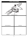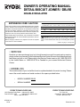
1
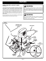
OWNER'S OPERATING MANUAL
DETAIL BISCUIT JOINER / DBJ50
DOUBLE INSULATED
5
16
45°
3
2
1
3
4
32 1
0
90°
SPECIFICATIONS:
No Load Speed
Rating
Fence Angles
Fence Height Adjustment
With Fence Angle Set on 90°
With Fence Angle Set on 45°
Depth Of Cut
With Micro Depth Of Cut Adjustment
Net Weight
19,000 rpm
120 volts, 60 Hz, AC
3.5 Amperes
45° and 90°
0 - 3/4 in.
5/16 in. - 13/16 in.
0 - 9/32 in. (0 - 7 mm)
3.625 lbs (1.65 kg.)
THANK YOU FOR BUYING A RYOBI DETAIL BISCUIT JOINER.
Your new detail biscuit joiner has been engineered and manufactured to Ryobi's high standard for dependability, ease of
operation, and operator safety. Properly cared for, it will give you years of rugged, trouble-free performance.
CAUTION: Carefully read through this entire owner's manual before using your new detail biscuit joiner.
Pay close attention to the Rules for Safe Operation, Warnings, and Cautions. If you use your detail biscuit joiner properly and
only for what it is intended, you will enjoy years of safe, reliable service.
Thank you again for buying Ryobi tools.
SAVE THIS MANUAL FOR FUTURE REFERENCE
RULES FOR SAFE OPERATION
The purpose of safety symbols is to attract your attention to possible dangers. The safety symbols, and the
explanations with them, deserve your careful attention and understanding. The safety warnings do not by
themselves eliminate any danger. The instructions or warnings they give are not substitutes for proper accident
prevention measures.
SYMBOL
MEANING
SAFETY ALERT SYMBOL:
Indicates caution or warning. May be used in conjunction with other symbols or pictographs.
DANGER: Failure to obey a safety warning will result in serious injury to yourself or to others. Always
follow the safety precautions to reduce the risk of fire, electric shock and personal injury.
WARNING: Failure to obey a safety warning can result in serious injury to yourself or to others. Always
follow the safety precautions to reduce the risk of fire, electric shock and personal injury.
CAUTION: Failure to obey a safety warning may result in property damage or personal injury to yourself
or to others. Always follow the safety precautions to reduce the risk of fire, electric shock and personal
injury.
NOTE:
Advises you of information or instructions vital to the operation or maintenance of the equipment.
IMPORTANT
DANGER:
Servicing of a tool with double insulation requires
extreme care and knowledge of the system and should
be performed only by a qualified service technician.
For service we suggest you return the tool to your
nearest RYOBI AUTHORIZED SERVICE CENTER for
repair. When servicing use only identical Ryobi
replacement parts.
To avoid serious personal injury, keep hands out of
blade path.
DOUBLE INSULATION
Double insulation is a concept in safety, in electric power
tools, which eliminates the need for the usual three-wire
grounded power cord. All exposed metal parts are isolated
from the internal metal motor components with protecting
insulation. Double insulated tools do not need to be grounded.
WARNING:
The double insulated system is intended to protect the
user from shock resulting from a break in the tool's
internal wiring. Observe all normal safety precautions
related to avoiding electrical shock.
WARNING:
Do not attempt to operate this tool until you have read
thoroughly and understand completely all instructions,
safety rules, etc. contained in this manual. Failure to
comply can result in accidents involving fire, electric
shock, or serious personal injury. Save owner's manual
and review frequently for continuing safe operation, and
instructing others who may use this tool.
Page 2
READ ALL INSTRUCTIONS
1. KNOW YOUR POWER TOOL. Read owner's
manual carefully. Learn its applications and
limitations as well as the specific potential
hazards related to this tool.
2. GUARD AGAINST ELECTRICAL SHOCK
BY PREVENTING BODY CONTACT WITH
GROUNDED SURFACES. For example:
Pipes, radiators, ranges, refrigerator
enclosures.
3. KEEP WORK AREA CLEAN. Cluttered areas
and benches invite accidents.
14. SECURE WORK. Use clamps or a vise to
hold work. It's safer than using your hand and
it frees both hands to operate tool.
15. DON'T OVERREACH. Keep proper footing
and balance at all times. Do not use on a
ladder or unstable support.
16. MAINTAIN TOOLS WITH CARE. Keep tools
sharp at all times, and clean for best and
safest performance. Follow instructions for
lubricating and changing accessories.
4. AVOID DANGEROUS ENVIRONMENT.
Don't use power tools in damp or wet locations
or expose to rain. Keep work area well lit.
17. DISCONNECT TOOLS. When not in use,
before servicing, or when changing
attachments, blades, bits, cutters, etc., all
tools should be disconnected.
5. KEEP CHILDREN AND VISITORS AWAY.
All visitors should wear safety glasses and be
kept a safe distance from work area. Do not let
visitors contact tool or extension cord.
18. REMOVE ADJUSTING KEYS AND
WRENCHES. Form habit of checking to see
that keys and adjusting wrenches are removed
from tool before turning it on.
6. STORE IDLE TOOLS. When not in use tools
should be stored in a dry, high or locked-up
place – out of the reach of children.
19. AVOID ACCIDENTAL STARTING. Don't
carry plugged-in tool with finger on switch. Be
sure switch is off when plugging in.
7. DON'T FORCE TOOL. It will do the job better
and safer at the rate for which it was designed.
20. MAKE SURE YOUR EXTENSION CORD IS
IN GOOD CONDITION. When using an
extension cord, be sure to use one heavy
enough to carry the current your product will
draw. An undersized cord will cause a drop in
line voltage resulting in loss of power and
overheating. A wire gage size (A.W.G.) of at
least 16 is recommended for an extension
cord 50 feet or less in length. A cord exceeding
100 feet is not recommended. If in doubt, use
the next heavier gage. The smaller the gage
number, the heavier the cord.
8. USE RIGHT TOOL. Don't force small tool or
attachment to do the job of a heavy duty tool.
Don't use tool for purpose not intended – for
example – Don't use a circular saw for cutting
tree limbs or logs.
9. DRESS PROPERLY. Do not wear loose
clothing or jewelry. They can be caught in
moving parts. Rubber gloves and nonskid
footwear are recommended when working
outdoors. Also, wear protective hair covering
to contain long hair and keep it from being
drawn into air vents.
10. ALWAYS WEAR SAFETY GLASSES WITH
SIDE SHIELDS. Everyday eyeglasses have
only impact resistant lenses; they are NOT
safety glasses.
11. PROTECT YOUR LUNGS. Wear a face or
dust mask if operation is dusty.
12. PROTECT YOUR HEARING. Wear hearing
protection during extended periods of
operation.
13. DON'T ABUSE CORD. Never carry tool by
cord or yank it to disconnect from receptacle.
Keep cord from heat, oil, and sharp edges.
21. OUTDOOR USE EXTENSION CORDS.
When tool is used outdoors, use only extension
cords intended for use outdoors. Outdoor
approved cords are marked with the suffix WA, for example - SJTW-A or SJOW-A.
22. KEEP BLADES CLEAN AND SHARP. Sharp
blades minimize stalling and kickback.
23. KEEP HANDS AWAY FROM CUTTING
AREA. Keep hands away from blades. Do not
reach underneath work while blade is rotating.
WARNING: BLADES COAST AFTER TURN
OFF.
24. NEVER USE IN AN EXPLOSIVE
ATMOSPHERE. Normal sparking of the motor
could ignite flammable liquids, gases, or
fumes.
Page 3
RULES FOR SAFE OPERATION (Continued)
25. INSPECT TOOL CORDS PERIODICALLY
and if damaged, have repaired at your nearest
authorized service center. Stay constantly
aware of cord location and keep it well away
from the rotating blade.
26. INSPECT EXTENSION CORDS PERIODICALLY and replace if damaged.
27. KEEP HANDLES DRY, CLEAN, AND FREE
FROM OIL AND GREASE. Always use a
clean cloth when cleaning. Never use brake
fluids, gasoline, petroleum-based products,
or any strong solvents to clean your tool.
28. STAY ALERT AND EXERCISE CONTROL.
Watch what you are doing and use common
sense. Do not operate tool when you are tired.
Do not rush.
29. CHECK DAMAGED PARTS. Before further
use of the tool, a guard or other part that is
damaged should be carefully checked to
determine that it will operate properly and
perform its intended function. Check for
alignment of moving parts, binding of moving
parts, breakage of parts, mounting, and any
other conditions that may affect its operation.
A guard or other part that is damaged should
be properly repaired or replaced by an
authorized service center.
30. DO NOT USE TOOL IF SWITCH DOES NOT
TURN IT ON AND OFF. Have switches
replaced by an authorized service center.
34. AVOID CUTTING NAILS. Inspect for and
remove all nails from lumber before cutting.
35. NEVER touch the blade or other moving parts
during use.
36. NEVER start a tool when the blade is in
contact with the workpiece.
37. NEVER lay a tool down before the blade has
come to a complete stop.
38. POLARIZED PLUGS. To reduce the risk of
electric shock, this equipment has a polarized
plug (one blade is wider than the other). This
plug will fit in a polarized outlet only one way.
If the plug does not fit fully in the outlet,
reverse the plug. If it still does not fit, contact
a qualified electrician to install the proper
outlet. Do not change the plug in any way.
39. WHEN SERVICING USE ONLY IDENTICAL
RYOBI REPLACEMENT PARTS.
40. SAVE THESE INSTRUCTIONS. Refer to them
frequently and use them to instruct others
who may use this tool. If you loan someone
this tool, loan them these instructions also.
WARNING:
Some dust created by power sanding, sawing, grinding,
drilling, and other construction activities contains
chemicals known to cause cancer, birth defects or
other reproductive harm. Some examples of these
chemicals are:
31. DRUGS, ALCOHOL, MEDICATION. Do not
operate this tool while under the influence of
drugs, alcohol, or any medication.
• lead from lead-based paints,
32. GUARD AGAINST KICKBACK. Kickback
occurs when the blade stalls rapidly and the
biscuit joiner is driven in the direction opposite
blade rotation. Release switch immediately if
blade binds or joiner stalls.
• arsenic and chromium from chemically-treated
lumber.
33. USE ONLY 1-1/2 in. (38 mm) DIAMETER
SPECIFIED BLADES. Do not use blades with
incorrect size holes. Never use blade washers
or bolts that are defective, incorrect, or not
specified.
• crystalline silica from bricks and cement and other
masonry products, and
Your risk from these exposures varies, depending on
how often you do this type of work. To reduce your
exposure to these chemicals: work in a well ventilated
area, and work with approved safety equipment, such
as those dust masks that are specially designed to filter
out microscopic particles.
SAVE THESE INSTRUCTIONS
Page 4
TABLE OF CONTENTS
■
■
■
■
■
■
■
■
■
■
Rules For Safe Operation ...........................................................2-4
Table of Contents / Introduction ..................................................... 5
Typical Applications ....................................................................... 6
Features .....................................................................................7-8
Adjustments..............................................................................9-10
Operation................................................................................ 11-16
Maintenance ...........................................................................17-19
Optional Accessories ................................................................... 19
Troubleshooting ........................................................................... 20
Service Information...................................................................... 22
INTRODUCTION
Spline joinery is one of the strongest methods of joinery
used in woodworking. When glue is properly applied to a
spline and to the joint area of the wood pieces being
connected, a large surface area receives the adhesion
properties of the glue. This forms a very strong joint.
Traditional spline joinery requires cutting slots with a router
or table saw. Small, thin strips of wood must then be cut to
fit inside the slots and act as splines.
Newer methods of spline joinery use a plate or biscuit
joiner to cut precise mating oval slots in adjoining boards.
Your new biscuit joiner is a fast, simple, and accurate
plunge cutting tool that can be used for this purpose. It can
be used to cut slots in hardwood, softwood, plywood, particle board, and other pressed woods.
Football shaped wafers, called biscuits, are then placed
inside the slots with glue and used to help line up adjoining
surfaces. When a water based glue is used, the biscuits
swell in the joint, making an extremely strong and firm
bond. White glue, yellow glue, carpenters glue, hide glue,
and aliphatic resin glue are examples of water based glues.
This bonding technique has traditionally been limited to
making edge-to-edge joints. However, with the use of your
new biscuit joiner, biscuits can now be easily used to
connect butt, miter, and T-joints. Biscuit joining can be as
strong as mortise and tenon, tongue and groove, standard
spline, and doweled joints. In most cases the material
around the biscuit will break before the biscuit itself will
break. A greater surface area is exposed to glue in a biscuit
joint, making the seams stronger.
WARNING:
WEAR YOUR
SAFETY
GLASSES
FORESIGHT IS BETTER
THAN NO SIGHT
The operation of any biscuit joiner can result in foreign objects being thrown into your
eyes, which can result in severe eye damage. Before beginning power tool operation,
always wear safety goggles or safety glasses with side shields and a full face shield
when needed. We recommend Wide Vision Safety Mask for use over eyeglasses or
standard safety glasses with side shields.
Look for this symbol to point out important safety precautions.
It means attention!!! Your safety is involved.
Page 5
TYPICAL APPLICATIONS
5
16
1
3
2
12
45
°
3
4
0
90
°
DETAIL BISCUIT JOINER / DBJ50
EDGE-TO-EDGE JOINTS
BUTT JOINTS
MITER JOINTS
T- JOINT
Page 6
FEATURES
Your detail biscuit joiner has been designed for making fast,
accurate, and simple plunge cuts in wood, etc. so that
biscuits can be used to join two or more boards together.
When used properly and only for what it is intended, this
versatile tool will give you years of trouble-free performance.
It is professionally engineered, but its ease of operation
allows the amateur to produce beautiful and precise work.
#R1 = 7/32 in. x 5/8 in.
SWITCH
#R2 = 9/32 in. x 3/4 in.
2
To turn your biscuit joiner ON, depress the switch trigger.
Release switch trigger to turn your biscuit joiner OFF.
MOTOR
Your biscuit joiner has a powerful motor with sufficient power
to handle tough cutting jobs. It develops a no load speed of
19,000 RPM.
#R3 = 1/2 in. x 1 in.
BLADE
3
Your biscuit joiner has a 1-1/2 in. (38 mm) 6 tooth blade for
cutting biscuit slots.
BISCUITS
See Figure 1.
Biscuits are available in three standard sizes:
#R1 (7/32 in. x 5/8 in.)
#R2 (9/32 in. x 3/4 in.)
#R3 (1/2 in. x 1 in.)
NOTE: Store biscuits in a dry place because they swell
rapidly upon contact with water-based woodworking glues.
REVERSIBLE FENCE FOR 45° AND 90° CUTS
Your biscuit joiner has a reversible fence. By loosening the
height adjustment knobs, the fence can be removed through
key hole slots. Once removed, it can be rotated 180° changing
the angle of cut from 90° to 45° or vice versa. The height of
the fence at 90° can be set between 0 to 3/4 in. from the
center of the blade. The height of the fence at 45° can be set
between 5/16 in. to 13/16 in. from the center of the blade.
The fence should always be used to guide and balance your
biscuit joiner, providing ease of operation and maintaining
safe control.
NONSKID BACKING PAD
The fence on your biscuit joiner is padded with a nonskid
backing pad to hold it stationary against the workpiece. It
helps prevent skidding when making cuts. It also prevents
marring of the workpiece from biscuit joiner when cutting.
Fig. 1
APPLICATIONS
(Use only for the purpose listed below)
■ Cutting precise mating oval slots in hardwood, softwood,
plywood, particle board, etc. for spline joinery applications.
ELECTRICAL CONNECTION
Your biscuit joiner has a precision built electric motor. It
should be connected to a power supply that is 120 volts,
60 Hz, AC only (normal household current). Do not
operate this tool on direct current (DC). A substantial voltage
drop will cause a loss of power and the motor will overheat.
If your biscuit joiner does not operate when plugged into an
outlet, double-check the power supply.
DEPTH ADJUSTMENT KNOB
A spring loaded depth adjustment knob makes it possible to
make proper settings for three standard size biscuits. Fine
adjustments to the cutting depth can be made with a knurled
adjustment knob and jam nut located behind the depth
adjustment knob. Once the correct depth setting has been
made for one biscuit size, the other two depth settings will be
automatically set.
INDICATOR MARKS
Centerline and line of cut indicator marks have been provided
on your biscuit joiner. See Figure 2.
WARNING:
Your detail biscuit joiner should never be connected to power supply when you are assembling parts, making
adjustments, assembling or removing blades, cleaning or when not in use. Disconnecting your detail biscuit joiner will
prevent accidental starting that could cause serious personal injury.
Page 7
O
A
b
p
FEATURES
KNOW YOUR DETAIL BISCUIT JOINER
See Figure 2.
Your biscuit joiner has been shipped completely assembled
and ready for use. An owner's manual and warranty
registration are also included. Inspect your new biscuit joiner
carefully to make sure no breakage or damage has occurred
during shipping. If any parts are damaged or missing, contact
your local Ryobi factory or authorized service center to
obtain replacement parts before attempting to operate your
biscuit joiner.
Before attempting to use any tool familiarize yourself with all
operating features and safety requirements.
WARNING:
Do not attempt to modify this tool or create accessories
not recommended for use with this tool. Any such
alteration or modification is misuse and could result in a
hazardous condition leading to possible serious personal
injury.
WARNING:
Do not allow familiarity with tools to make you careless.
Remember that a careless fraction of a second is
sufficient to inflict severe injury.
LINE OF
CUT WINDOW
CENTERLINE / LINE
OF CUT INDICATOR
MARK(S)
REAR HANDLE
WIDTH OF
CUT SCALE
DEPTH
ADJUSTMENT
KNOB
SWITCH
TRIGGER
KNURLED
ADJUSTMENT
KNOB
JAM
NUT
FENCE
HEIGHT
SETTING SCALE
5
16
45°
3
4
3
2
1
5
16
45°
32 1
0
90°
FRONT
BASE
HEIGHT
ADJUSTMENT
KNOBS (2)
NONSKID
BACKING PAD
3
4
REAR
BASE
BOTTOM
SHOE
0
90°
HEIGHT
INDICATOR MARK
Fig. 2
Page 8
ADJUSTMENTS
WARNING:
DEPTH
INDICATOR
MARK
If any parts are missing, do not operate tool until the
missing parts are replaced. Failure to do so could result
in possible serious personal injury.
ROTATE TO
DESIRED SETTING
1, 2, OR 3
DEPTH OF CUT ADJUSTMENTS
3
PULL AND HOLD TO
ROTATE DEPTH
ADJUSTMENT KNOB
2
Your biscuit joiner can be adjusted to three standard
cutting depths to accommodate three standard size biscuits
— #R1, #R2, and #R3. Adjustments are made by engaging
slots on depth adjustment knob with tabs on rear base. For
example, when using a #R1 size biscuit, rotate the depth
adjustment knob until the slot marked 1 aligns with the
depth indicator mark on the rear base. When using a #R2
size biscuit, rotate the depth adjustment knob until the slot
marked 2 aligns with the depth indicator mark on the rear
base, and when using a #R3 size biscuit rotate the depth
adjustment knob until the slot marked 3 aligns with the
depth indicator mark on the rear base. See Figure 3.
REAR
BASE
RELEASE TO APPLY
PRESSURE AGAINST DEPTH
ADJUSTMENT KNOB
KNURLED
ADJUSTMENT
KNOB
TABS
TO SET DEPTH ADJUSTMENT KNOB
■ Unplug your detail biscuit joiner.
JAM
NUT
WARNING:
Failure to unplug biscuit joiner could result in accidental
starting causing possible serious personal injury.
SLOT
■ Pull knurled adjustment knob and jam nut in the direction
of the arrow shown in figure 3.
NOTE: Knob and jam nut are spring loaded, therefore
pulling them in the direction of the arrow shown puts
pressure on the spring and releases pressure from the
depth adjustment knob.
■ Rotate depth adjustment knob until desired slot setting
aligns with tabs on rear base — 1, 2, or 3.
■ Next release knurled adjustment knob and jam nut applying
pressure from spring on depth adjustment knob.
TO MAKE FINE ADJUSTMENTS
See Figure 4.
■ Unplug your detail biscuit joiner.
■ Loosen knurled adjustment knob. This knob is used as a
lock nut only. Loosen by twisting it in the opposite direction away from jam nut.
Fig. 3
3
2
Make a test cut in a scrap piece of wood. Fit the correct size
biscuit into biscuit slot. If biscuit slot is too deep or too
shallow, fine adjustments to the depth setting can be made
by loosening knurled adjustment knob and making fine
adjustments with the jam nut. Turning jam nut forward will cut
shallow biscuit slots. Turning jam nut backwards will cut
deeper biscuit slots. The biscuit slot should be deep enough
to allow slightly more than one-half of the biscuit into the slot.
This extra room allows for proper alignment of the wood
being joined.
DEPTH
ADJUSTMENT
KNOB
TURN FORWARD
FOR SHALLOW
BISCUIT SLOTS
TURN BACKWARDS FOR
DEEPER BISCUIT SLOTS
KNURLED ADJUSTMENT KNOB USED AS A LOCK NUT.
JAM NUT USED TO MAKE FINE ADJUSTMENTS. Fig. 4
■ Turn jam nut forward for a more shallow cut, or
backwards for a deeper cut.
■ Once desired depth of cut is reached, hold jam nut so that
it will not move out of adjustment. Next, tighten knurled
adjustment knob against jam nut.
■ Recheck depth setting by making a test cut in a scrap
piece of wood. Also periodically check depth setting for
accuracy. See Figure 4.
Page 9
ADJUSTMENTS
FENCE HEIGHT ADJUSTMENT
See Figure 5.
The fence on your biscuit joiner can be moved up and down
to adjust the position of the blade in relation to the top of the
workpiece. A scale on both sides of the front base indicates
height settings for both 45° and 90° angles. The fence and
height indicator mark can be positioned from 5/16 in. to 13/16
in. from the center of the blade for 45° angles. It can be
positioned from 0 to 3/4 in. from the center of the blade for 90°
angles. Scale marks are in increments of 1/16 in.
FENCE
HEIGHT
ADJUSTMENT
KNOB(S)
5
16
45°
3
4
0
90°
TO ADJUST HEIGHT SETTING
See Figure 5.
■ Unplug your detail biscuit joiner.
HEIGHT
SETTING SCALE
Fig. 5
TO LOWER
FENCE
WARNING:
Failure to unplug your detail biscuit joiner could result in
accidental starting causing possible serious personal
injury.
■ Loosen the two height adjustment knobs.
■ Pull the fence forward and slide it up or down until the
height indicator mark is aligned with the desired dimension on the scale.
■ Tighten height adjustment knobs securely.
3
4
0
90°
32 1
HEIGHT
ADJUSTMENT
KNOBS
(1) PULL
FORWARD
3
2
1
NOTE: Slots in the front base align with a tab on the
backside of the fence. See Figure 6. This alignment
keeps the fence square at each height setting.
5
16
45°
FENCE ROTATION / ANGLE ADJUSTMENT
FENCE
See Figure 6.
The fence on your biscuit joiner can be rotated 180° and set
at either 45° or 90° angles.
FRONT
BASE
(2) SLIDE
DOWN
FENCE ORIENTATION
FOR 45° ANGLES
TO ROTATE FENCE / CHANGE ANGLE SETTING
See Figure 6.
■ Unplug your detail biscuit joiner.
WARNING:
Failure to unplug your detail biscuit joiner could result in
accidental starting causing possible serious personal
injury.
■ Loosen the two height adjustment knobs.
■ Pull the fence forward and slide it down the front base until
it can be removed through the key hole slots.
■ Rotate the fence 180°.
■ Reinstall the fence on the front base. Place height adjustment knob bolts in key hole slots and align bolt heads with
the slots on back of front base.
■ Slide fence up the front base to desired depth of cut.
■ Tighten height adjustment knobs securely. See Figure 6.
HEIGHT
ADJUSTMENT
KNOB BOLT(S)
SLOTS
TABS
KEY
HOLE
SLOTS
FENCE ORIENTATION
FOR 90° ANGLES
SLOT(S)
FRONT
BASE
Fig. 6
Page 10
OPERATION
WARNING:
Always wear safety goggles or safety glasses with side
shields when operating tools. Failure to do so could
result in objects being thrown into your eyes, resulting in
possible serious injury.
INDICATOR
MARK(S)
3
21
12
A variety of spline joints can be made using your biscuit
joiner. The number and size biscuits needed for each joint
depends on the thickness of the wood and the length of the
joint. In general, the small #R1 biscuits should be used for
miter cuts in small, thin materials. The larger biscuits should
be used for edge-to-edge joinery.
When joining thick materials, stack two biscuits, one above
the other. For example, joining 2 in. x 4 in. dressed lumber.
See Figure 9. When joining even thicker materials, use
additional biscuits, stacked above each other.
When making edge-to-edge joints the more biscuits you use,
the stronger the joint will be.
The following sections illustrate how to make various spline
joints using your biscuit joiner.
3
LINE OF
CENTERLINE
CUT
WINDOW
MARK(S)
TOP VIEW OF DETAIL BISCUIT JOINER
Fig. 7
CENTERLINE
MARKS
EDGE-TO-EDGE JOINTS
See Figures 7 and 8.
Edge-to-edge joinery is one of the most basic and easiest
joints to construct. In general, two basic adjustments have
to be made for all biscuit joinery applications. One is the
depth of cut and the other is the location of the cut.
BISCUIT(S)
HOW TO MAKE EDGE-TO-EDGE JOINTS
■ Unplug your detail biscuit joiner.
■ Prepare the workpieces by laying them side by side on a
workbench in the order in which they will be assembled.
■ Using a square, determine the location of each biscuit
spline joint and mark the center of each joint by drawing
a line across each workpiece. Mark the edges 1 in. from
the ends of workpieces. The joint will be stronger if you
use multiple biscuits placed close together.
■ Set fence angle at 90°.
■ Loosen height adjustment knobs, then pull and slide the
fence up or down until the indicator point is aligned with
the desired dimension on the scale. REMEMBER: The
scale indicates the height of the fence from the center of
blade.
■ Tighten height adjustment knobs securely.
■ Select the correct depth of cut setting to match the biscuit
size you are planning to use. We suggest that you make
a test cut in a scrap piece of wood from the same
workpiece if possible.
■ Clamp workpiece securely so that it will not move during
the cut.
■ Plug your biscuit joiner into power supply and prepare to
make your first cut. Grasp and hold your biscuit joiner
securely with both hands.
BISCUIT SLOT(S)
EDGE-TO-EDGE JOINTS
Fig. 8
■ Place the fence against the board and align the indicator
marks on the fence with the centerline mark(s) on the
board. See Figure 7.
■ Depress the switch trigger and let the motor build to its
maximum speed, then gradually push biscuit joiner forward
to extend the blade into the wood.
■ When the base assembly bottoms out against the depth
of cut adjustment knob setting, pull back releasing pressure
on the spring. Blade will retract from biscuit slot.
■ Repeat this procedure for all desired biscuit slots.
■ Once all biscuit slots have been cut, place a biscuit in
each joint and dry assemble the workpieces. Make sure
each joint lines up and fits.
■ Finally, disassemble the workpieces and place a bead of
glue in each slot. Also, spread a bead of glue over the
entire surface of the joint. Reinsert the biscuits and
assemble the workpieces. See Figure 8.
■ Clamp workpieces together until the glue sets up.
Page 11
OPERATION
BUTT JOINTS
See Figure 9.
A butt joint is one of the weakest joints in woodworking.
This type of joint is mating the end grain of one board with
the edge grain of another. The bonding of glue on this type
of surface is poor. However, by using biscuits you can
create a very strong joint that gives a mortise-and-tenon
effect.
BISCUIT
SLOT(S)
BISCUIT(S)
HOW TO MAKE BUTT JOINTS
■ Unplug your detail biscuit joiner.
■ Place the two pieces of wood to be joined on a level
workbench. Align them against each other in the
arrangement in which they will be assembled.
■ Using a square, determine the location of each biscuit
spline joint and mark the center of each joint by drawing
a line across the edges of the two boards.
■ Set fence angle at 90°.
■ Loosen height adjustment knobs, then pull and slide the
fence up or down until the indicator point is aligned with
the desired dimension on the scale. REMEMBER: The
scale indicates the height of the fence from the center of
the blade.
■ Tighten height adjustment knobs securely.
■ Select the correct depth of cut setting to match the biscuit
size you are planning to use. We suggest that you make
a test cut in a scrap piece of wood from the same
workpiece if possible.
■ Clamp workpiece securely so that it will not move during
the cut.
■ Plug your biscuit joiner into power supply and prepare to
make your first cut. Grasp and hold your biscuit joiner
securely with both hands.
■ Place the fence against the board and align the indicator
marks on the fence with the centerline mark(s) on the
board.
■ Depress the switch trigger and let the motor build to its
maximum speed, then gradually push biscuit joiner forward
to extend the blade into the wood.
■ When the base assembly bottoms out against the depth
of cut adjustment knob setting, pull back releasing pressure
on the spring. Blade will retract from biscuit slot.
■ Repeat this procedure for cutting the slot in the mating
workpiece.
■ Once all biscuit slots have been cut, place a biscuit in
each joint and dry assemble the workpieces. Make sure
each joint lines up and fits.
■ Finally, disassemble the workpieces and place a bead of
glue in each slot. Also, spread a bead of glue over the
entire surface of the joint. Reinsert the biscuits and
assemble the workpieces. See Figure 9.
■ Clamp workpieces together until the glue sets up.
CENTERLINE
MARK(S)
MULTIPLE
BISCUITS STACKED
BUTT JOINTS
Fig. 9
OFFSET BUTT JOINT
BISCUIT
SLOT
BISCUIT
CENTERLINE
MARK(S)
Fig. 10
OFFSET BUTT JOINTS
See Figure 10.
The rails of a table or workbench are often offset from the
front of the table legs. When offsets are required, it is
necessary to cut the slots in the rails first, then re-adjust the
fence to cut the slots in the legs.
Keeping this one exception in mind, the procedure for cutting
offset butt joints is identical to the procedure for cutting butt
joints.
For example — If a 1/4 in. offset is desired, you would mark
the centerlines for cutting a butt joint as mentioned in the
procedures for cutting butt joints, and cut the slots in the ends
of the rails. Next you would raise the fence 1/4 in. to the
desired offset and cut the slots in the legs.
Page 12
OPERATION
T- JOINTS
See Figures 11-15.
A T-joint is used when the end of a board is joined to the
face of another board as shown in figure 11. Attaching
shelves to bookcases and inner support braces to frames
are typical applications. Actual cutting of a T-joint is as
simple as any other cut. However, it is critical that you mark
the centerlines, mark the intersection points for each slot,
and cut each slot correctly. See Figure 11.
CENTERLINE
MARK(S)
BISCUIT(S)
HOW TO MAKE T- JOINTS
■ Unplug your detail biscuit joiner.
■ Place the two pieces of wood to be joined on a level
workbench as shown in figure 12. The inside face of the
vertical board should be facing up.
■ Determine the location of each biscuit joint and mark the
centerlines on each board as shown. The centerlines for
both boards must line-up with each other. Measure
carefully, these measurements must be accurate and
precise. TIP: Measure twice and cut once. In addition to
the centerlines lining up, the spacing of the biscuit slots
from side-to-side must also match.
■ Plug your biscuit joiner into power supply and cut slots in
all boards that require end slots. See Figure 13. Follow
procedures explained in "Edge-To-Edge Joints". Rotate
fence angle to 90°, set fence height at desired dimension
on the scale, select the correct depth of cut setting for the
biscuit size you plan to use, clamp workpiece securely,
then cut each slot at the marked centerline intersection.
■ Next, you must remove the fence from your biscuit joiner
in order to cut slots into the face of the vertical board.
TO REMOVE FENCE:
■ Unplug your detail biscuit joiner.
■ Loosen height adjustment knobs, pull fence forward and
slide it down the front base until it can be removed through
the key hole slots. See Figure 14. Next, select the correct
depth of cut setting for the biscuit size you plan to use,
clamp workpiece securely, and cut each slot at the marked
centerline intersection.
BISCUIT SLOT(S)
Fig. 11
T- JOINT
HORIZONTAL BOARD
BISCUIT SLOT
CENTERLINE MARK(S)
BOARD
CENTERLINES
VERTICAL BOARD
Fig. 12
HORIZONTAL BOARD
WARNING:
When the fence is removed, the cutter may be exposed.
Use extreme caution to avoid serious personal injury.
3
2
1
5
16
45°
3
4
0
90°
■ Place your biscuit joiner on vertical board as shown in
figure 15 and align indicator marks on bottom shoe with
centerline on vertical board.
■ Place a straight piece of wood on the vertical board and
securely clamp it flush against the bottom shoe. This piece
of wood is used for a fence or guide. It must be square with
the sides of the vertical board and parallel with the
centerline.
■ Align centerline on bottom of shoe with marked intersection
for biscuit slot.
Page 13
CLAMP
TO CUT END SLOTS IN
HORIZONTAL BOARDS
Fig. 13
OPERATION
T-JOINTS (Continued)
■ Plug your biscuit joiner into power supply and prepare to
cut slot.
■ Depress the switch trigger and let the motor build to its
maximum speed, then gradually push biscuit joiner forward
to extend the blade into the wood.
■ When the base assembly bottoms out against the depth of
cut adjustment knob setting, pull back releasing pressure
on the spring. Blade will retract from biscuit slot.
■ Repeat this procedure for cutting all required slots in
vertical boards.
■ Once all slots have been cut, place a biscuit in each joint
and dry assemble the workpieces. Make sure each joint
lines up and fits.
■ Finally, disassemble the workpieces and place a bead of
glue in each slot. Also, spread a bead of glue over the
entire surface of the joint. Reinsert the biscuits and
assemble the workpieces. See Figure 11.
■ Clamp workpieces together until the glue sets up.
Upon completion of a T-joint cutting operation, reinstall
the fence on the front base by reversing "TO REMOVE
FENCE" procedure. Place height adjustment knob bolts in
key hole slots and align bolt heads with the slots on back of
front base. Slide fence up the front base to desired depth of
cut. Tighten height adjustment knobs securely.
5
16
45°
3
4
0
90°
REMOVE FENCE TO MAKE
FACE CUTS IN VERTICAL BOARDS
Fig. 14
BOTTOM SIDE OF BOTTOM SHOE
CENTERLINE MARK
ON WORKPIECE
INDICATOR
MARK
HORIZONTAL
BOARD
MITER JOINTS
See Figures16-18.
There are two types of miter joints that can be made using
biscuits: flat miters and edge miters. Flat miters are used
when making picture frames. Edge miters are used when
making boxes or things where you don't want to show the
end grain of the wood. Butt joints show the end grain in
wood.
HOW TO MAKE FLAT MITER JOINTS
■ Unplug your detail biscuit joiner.
WARNING:
Failure to unplug your detail biscuit joiner could result in
accidental starting causing possible serious personal injury.
■ Place the pieces of wood to be joined on a level
workbench as shown in figure 16.
■ Using a combination square, draw a line through the
center of each joint perpendicular to the mitered edges.
■ Set fence angle at 90°, set fence height at desired dimension
on the scale, select the correct depth of cut setting for the
biscuit size you plan to use, and clamp workpiece securely.
■ Align indicator mark on fence with the centerline on the
workpiece.
■ Plug your biscuit joiner into power supply and prepare to
cut slot.
Page 14
VERTICAL
BOARD
Fig. 15
TO CUT SLOTS IN VERTICAL BOARDS
CLAMP
CENTERLINE
MARK(S)
BISCUIT
SLOT
FLAT MITER JOINTS
BISCUIT
Fig. 16
OPERATION
FLAT MITER JOINTS (Continued)
■ Depress the switch trigger and let the motor build to its
maximum speed, then gradually push biscuit joiner forward
to extend the blade into the wood.
■ When the base assembly bottoms out against the depth of
cut adjustment knob setting, pull back releasing pressure
on the spring. Blade will retract from biscuit slot.
■ Repeat this procedure for cutting mating slot and all
required miter joint slots.
■ Once all slots have been cut, place a biscuit in each joint
and dry assemble the workpieces. Make sure each joint
lines up and fits.
■ Finally, disassemble the workpieces and place a bead of
glue in each slot. Also, spread a bead of glue over the
entire surface of the joint. Reinsert the biscuits and
assemble the workpieces. See Figure 16.
BISCUIT
SLOT
CENTERLINE
MARK(S)
EDGE MITER JOINTS
■ Clamp workpieces together until the glue sets up.
Fig. 17
CUTTING EDGE MITER SLOT
FROM LONG SIDE OF WORKPIECE
HOW TO MAKE EDGE MITER JOINTS
45
16
5
°
4
3
0
90
°
■ Unplug your detail biscuit joiner.
■ Place the pieces of wood to be joined on a level workbench
as shown in figure 17.
■ Mark centerline of the joint on each board.
■ When making edge miter joints with workpieces that have
different thicknesses, clamp securely to a workbench
with the long sides up. This will assure that the outside
surfaces will match. See Figure 18.
■ Set fence angle at 45°.
■ Slide the fence up or down until fence height is at desired
setting.
■ Tighten height adjustment knobs securely.
■ Place your biscuit joiner on workpiece with the fence
resting on the long side of workpiece as shown in figure
18. The front base should be against the mitered edge of
the workpiece.
■ Recheck fence height setting to make sure it will not cut
through the workpiece.
■ Align indicator mark on fence with the centerline on the
workpiece. Make sure the front base is pressed flat
against the mitered edge of the workpiece.
■ Plug your biscuit joiner into power supply and prepare to
cut slot.
■ Depress the switch trigger and let the motor build to its
maximum speed, then gradually push biscuit joiner forward
to extend the blade into the wood.
■ When the base assembly bottoms out against the depth
of cut adjustment knob setting, pull back releasing pressure on the spring. Blade will retract from biscuit slot.
BISCUIT
Fig. 18
■ Repeat this procedure for cutting mating slot and all
required miter joint slots.
■ Once all slots have been cut, place a biscuit in each joint
and dry assemble the workpieces. Make sure each joint
lines up and fits.
■ Finally, disassemble workpieces and place a bead of glue
in each slot. Also, spread a bead of glue over the entire
surface of the joint. Reinsert the biscuits and assemble
workpieces. See Figure 17.
■ Clamp workpieces together until the glue sets up.
Page 15
OPERATION
HINGE JOINTS
See Figure 19.
Hinge joints are used when joining two boards using hinges
supplied in one of Ryobi's optional hinge kits. Jewelry boxes,
doors on clocks, recipe boxes, etc. are typical applications.
HINGE
SLOT(S)
HOW TO MAKE HINGE JOINTS
■ Unplug your detail biscuit joiner.
■ Prepare the workpieces to be joined by laying them side
by side on a workbench in the order in which they will be
hinged.
■ Determine the location of each hinge joint and mark the
center of each joint by drawing a line across each workpiece.
■ Set fence angle at 90°.
■ Loosen height adjustment knobs, then pull and slide the
fence down the scale until the height indicator mark is set
at zero depth of cut. REMEMBER: The scale indicates the
height of the fence from the center of the blade, which is
approximately .050 of an inch.
■ Tighten height adjustment knobs securely.
■ Select the #3 depth of cut setting. We suggest that you
make a test cut in a scrap piece of wood from the same
workpiece if possible.
■ Clamp workpiece securely so that it will not move during
the cut.
■ Plug your biscuit joiner into power supply and prepare to
make your first cut. Grasp and hold your biscuit joiner
securely with both hands.
■ Place the fence against the board and align the indicator
marks on the fence with the centerline mark(s) on the
board. See Figure 19.
■ Depress the switch trigger and let the motor build to its
maximum speed, then gradually push biscuit joiner forward
to extend the blade into the wood.
■ When the base assembly bottoms out against the depth
of cut adjustment knob setting, pull back releasing pressure
on the spring. Blade will retract from hinge slot.
■ Repeat this procedure for all desired hinge slots.
■ Once all hinge slots have been cut, place a hinge in each
slot and dry assemble the workpieces. Make sure each
slot lines up and fits.
■ Finally, assemble the hinges to the workpieces and
secure with the fasteners supplied.
HINGE
FASTENERS
HINGE
Fig. 19
EXTENSION CORDS
The use of any extension cord will cause some loss of power.
To keep the loss to a minimum and to prevent tool overheating,
use an extension cord that is heavy enough to carry the
current the tool will draw.
A wire gage size (A.W.G.) of at least 16 is recommended for
an extension cord 50 feet or less in length. When working
outdoors, use an extension cord that is suitable for outdoor
use. The cord's jacket will be marked WA.
WARNING:
Check extension cords before each use. If damaged,
replace immediately. Never use tool with a damaged
cord since touching the damaged area could cause
electrical shock resulting in serious injury.
CAUTION:
Keep extension cords away from the cutting area and
position the cord so that it will not get caught on lumber,
tools, etc. during cutting operations.
LUBRICATION
All of the bearings in this tool are lubricated with a sufficient
amount of high grade lubricant for the life of the unit under
normal operating conditions. Therefore, no further lubrication
is required.
Page 16
MAINTENANCE
BLADE REPLACEMENT
SCREWS (4)
See Figures 20– 22.
After extended use, the blade on your biscuit joiner may
become dull. If you accidentally hit a nail or other blunt
object, it will dull or break the blade. These situations
require replacing the blade.
BOTTOM
SHOE
HOW TO REPLACE THE BLADE
■ Unplug your detail biscuit joiner.
WARNING:
Failure to unplug your detail biscuit joiner could result in
accidental starting causing possible serious personal injury.
3
■ Place your biscuit joiner upside down on a workbench and
remove the bottom shoe screws (4) and bottom shoe. See
Figure 20.
■ Place a #1 Phillips screwdriver or 3/16 in. diameter pin
between the blade and front base. See Figure 21.
■ Place one of the blade teeth against the screwdriver or pin
and lock blade preventing it from rotating.
■ Using a 9/64 in. hex key, remove blade screw.
NOTE: Turn blade screw counterclockwise to remove.
See Figure 22.
■ Remove outer blade washer and blade.
■ Clean wood particles and resin from blade washer and all
surrounding parts.
2
Fig. 20
#1 PHILLIPS SCREWDRIVER
OR 3/16 in. DIAMETER PIN
BLADE
FRONT BASE
WARNING:
2
3
If inner blade washer has been removed, replace it
before installing new blade. Failure to do so could cause
an accident since blade screw will not tighten properly.
OUTER
BLADE WASHER
BLADE SCREW
GEAR
SPINDLE
FLATS
BLADE
BLADE
FLATS
INNER
BLADE
WASHER
GEAR
SPINDLE
2
3
■ Place inner blade washer on gear spindle. See Figure 22.
■ Place new blade onto gear spindle and align flats on blade
with flats on gear spindle.
■ Secure with outer blade washer and blade screw.
■ Place a #1 Phillips screwdriver or 3/16 in. diameter pin
between the blade and front base. See Figure 21.
■ Place one of the blade teeth against the screwdriver or pin
and lock blade preventing it from rotating.
NOTE: Blade teeth point toward the right of your biscuit
joiner when held in normal operating position. An arrow
on the bottom shoe also indicates direction of blade
rotation. See Figure 20.
■ Tighten blade screw securely.
NOTE: Turn blade screw clockwise to tighten.
■ Reassemble bottom shoe.
■ Replace screws (4) and tighten securely.
Fig. 21
Fig. 22
Page 17
MAINTENANCE
WARNING:
FRONT BASE
TO
REMOVE
SCREWDRIVER
When servicing, use only identical Ryobi replacement
parts. Use of any other part may create a hazard or
cause product damage.
CLEANING BASE ASSEMBLY
2
3
See Figures 23-25.
After extended use, wood particles and resin may build up
inside the base assembly of your biscuit joiner and clog the
path for wood particles going through dust exhaust opening.
Wood particles packing up in this area makes cutting biscuit
slots more difficult.
SCREW
HOLE
HOW TO CLEAN BASE ASSEMBLY
■ Unplug your detail biscuit joiner.
Fig. 23
WARNING:
Failure to unplug your detail biscuit joiner could result in
accidental starting causing possible serious personal injury.
■ Place your biscuit joiner upside down on a workbench and
remove the bottom shoe screws (4) and bottom shoe.
■ Remove the blade. See "Blade Replacement" section.
■ With your biscuit joiner still upside down on a workbench,
remove front base screws (2). See Figure 23.
■ Pull front base in the direction shown by the arrow in figure
23 and remove.
■ Using a pair of needle nose pliers, stretch and release
springs from tabs on bearing plate. See Figure 24.
■ Lift adjustment rod away from bearing plate and remove
rear base.
■ With front and rear base assemblies removed, place your
biscuit joiner upside down on a workbench and clean
wood particles and resin from bearing plate and surrounding
areas. NOTE: Also clean the blade, blade washers, etc.
NOTCH(ES)
REAR BASE
TAB(S)
BEARING
PLATE
SPRING(S)
Fig. 24
ADJUSTMENT
ROD
REAR
BASE SLOT
CAUTION:
Blade tips are sharp. Be carefull not to cut yourself
when cleaning.
■ Clean wood particles and resin from slots and surrounding
areas on front and rear base. See Figure 25. Apply a thin
coat of general purpose grease in slots or on bearing plate
where base slides.
■ Replace rear base. Position adjustment rod in its proper
place as shown in figure 24.
■ Secure rear base in place with the two springs. Hook one
end of each spring in notch on each side of rear base.
Using needle nose pliers, stretch each spring and hook it
over tabs on bearing plate.
■ Reassemble front base. Replace screws and tighten securely.
REAR
BASE SLOT
FRONT
BASE SLOT
FRONT
BASE SLOT
Fig. 25
■ Reinstall blade. Tighten blade screw securely.
■ Reassemble bottom shoe. Tighten screws (4) securely.
Page 18
MAINTENANCE
Avoid using solvents when cleaning plastic parts. Most
plastics are susceptible to damage from various types of
commercial solvents and may be damaged by their use.
Use clean cloths to remove dirt, dust, oil, grease, etc.
WARNING:
When electric tools are used on fiberglass it has been
found that they are subject to accelerated wear and possible
premature failure, as the fiberglass chips and grindings are
highly abrasive to bearings, brushes, commutator, etc.
Consequently it is not recommended that this tool be used
for extended work on any fiberglass material. During any
use on fiberglass it is extremely important that the tool is
cleaned frequently by blowing with an air jet.
Do not at any time let brake fluids, gasoline, petroleumbased products, penetrating oils, etc. come in contact
with plastic parts. They contain chemicals that can
damage, weaken or destroy plastic.
WARNING:
Always wear safety goggles or safety glasses with side
shields during power tool operation or when blowing
dust. If operation is dusty, also wear a dust mask.
OPTIONAL ACCESSORIES
The following recommended accessories are current and were available at the time this manual was printed:
Item No.
Description
Quantity
4600411
4600412
4600413
4600415
4600435
4600450
4600451
Size #R1 Accu Biscuits™, Canister Pack
Size #R2 Accu Biscuits™, Canister Pack
Size #R3 Accu Biscuits™, Canister Pack
Size #R3 Value Pack
High Speed Steel Blade
Brass Hinge Kit
Chrome Hinge Kit
110 Pcs.
100 Pcs.
90 Pcs.
Total 1000 Pcs.
1
6 Pcs.
6 Pcs.
HELPFUL HINTS
✓
✓
✓
✓
Always clamp workpiece securely before cutting.
✓
Always dry assemble your project before gluing it
together.
✓
✓
✓
For loose fit situations, wet biscuits to make them swell.
✓
✓
✓
✓
✓
✓
✓
Study all safety rules and do the job safely.
The more biscuits used, the stronger the joint will be.
✓
Keep blade clean. When the blade becomes dull,
replace it.
DO NOT ABUSE POWER TOOLS. Abusive practices
can damage tool as well as workpiece.
✓
THINK SAFETY BY THINKING AHEAD.
A safe operator is one who thinks ahead.
Always wear eye protection when cutting slots.
Make set-up adjustments carefully. Then double check.
Measure twice and cut once.
Don’t let familiarity make you careless.
Page 19
NEVER place your hands in jeopardy.
Make certain clamps can’t loosen while in use.
Test difficult set-ups on scrap—Don’t waste lumber.
Plan each operation before you begin.
Provide for smoother operation by cleaning your biscuit joiner frequently. Shake biscuit joiner or blow with
an air jet to remove wood particle build-up.
TROUBLESHOOTING
PROBLEM
SOLUTION
1. Biscuits do not fit slots. Biscuits not fitting slots may
also cause misalignment of boards being joined.
A. Biscuit slots are too deep or too shallow. Make fine
adjustments to depth setting. See "TO MAKE FINE
ADJUSTMENTS" section on page 9.
B. Biscuit thickness may be out of tolerance. Compress
biscuits in a vise if they are too thick.
C. Check to see if biscuits are the correct size for the
size slots that have been cut: #1, #2, or #3.
D. Check to see if biscuits have gotten wet and swollen.
E. If biscuits fit loose in slots, wet them to take up the
loose fit.
2. Wood particles begin to backup on front of unit.
A. Dust exhaust may be clogged preventing wood
particles from going through dust exhaust opening.
Remove bottom shoe and clean blade, bearing
plate, base assembly slots, and surrounding areas.
See "CLEANING BASE ASSEMBLY" section on
page 18.
3. Blade becomes difficult to push in when cutting
slots. Blade does not retract properly when cutting
slots.
A. Wood particles and resin have built up on base
assembly slots and surrounding areas. Remove
front and rear base assemblies and clean blade,
bearing plate, base assembly slots and surrounding
areas. Apply a thin coat of general purpose grease
in slots or on bearing plate where base slides. See
"CLEANING BASE ASSEMBLY" section on page
18.
4. Cutting performance is poor and there is a loss of
power or stalling of motor when cutting slots.
A. Blade is dull. Replace blade. See "BLADE
REPLACEMENT" section on page 17.
B. Resin has built up on blade. Remove blade and
clean it with gum and pitch remover. See "BLADE
REPLACEMENT" section on page 17 for blade
removing instructions. Once clean, follow "BLADE
REPLACEMENT" instructions to replace the blade.
Page 20
NOTES
Page 21
OWNER'S OPERATING MANUAL
DETAIL BISCUIT JOINER / DBJ50
DOUBLE INSULATED
EXTENSION CORD CAUTION
When using a power tool at a considerable distance from a power
source, be sure to use an extension cord that has the capacity to
handle the current the tool will draw. An undersized cord will cause
a drop in line voltage, resulting in overheating and loss of power.
Use the chart to determine the minimum wire size required in an
extension cord. Only round jacketed cords should be used.
When working with a tool outdoors, use an extension cord that is
designed for outside use. This is indicated by the letters "WA" on
the cord's jacket.
Before using any extension cord, inspect it for loose or exposed
wires and cut or worn insulation.
**Ampere rating
(on tool data plate)
0-2.0
Cord Length
2.1-3.4
3.5-5.0
5.1-7.0
7.1-12.0 12.1-16.0
Wire Size (A.W.G.)
25'
16
16
16
16
14
14
50'
16
16
16
14
14
12
100'
16
16
14
12
10
—
CAUTION: Keep the extension cord clear of the working
area. Position the cord so that it will not get caught on lumber,
tools or other obstructions while you are working with a power
tool.
**Used on 12 gauge - 20 amp circuit.
• SERVICE
Now that you have purchased your tool, should a need ever exist for repair parts or service,
simply contact your nearest Ryobi Authorized Service Center. Be sure to provide all pertinent
facts when you call or visit. Please refer to the Service Center insert or call 1-800-525-2579
in the United States or 1-800-265-6778 in Canada for your nearest Authorized Service
Center.
• MODEL NO.
The model number of your tool will be found on a plate attached to the motor housing. Please
record the model number and serial number in the space provided below.
•
MODEL NUMBER DBJ50
•
SERIAL NUMBER
RYOBI TECHNOLOGIES INC.
RYOBI TECHNOLOGIES INC.
1428 Pearman Dairy Road Anderson SC 29625
Post Office Box 1207
Anderson SC 29622-1207
Phone 1-800-525-2579
P.O. Box 910
Cambridge, Ontario N1R 6K2
Phone 1-800-265-6778
972000-311
10-00
Printed in U.S.A.