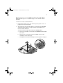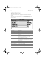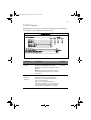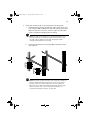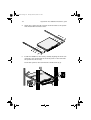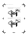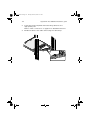
1
aa r300.book Page i Tuesday, March 4, 2003 9:39 AM
Altos R300
User’s guide
aa r300.book Page ii Tuesday, March 4, 2003 9:39 AM
Copyright © 2003 Acer Incorporated
All Rights Reserved.
Altos R300
User’s guide
Changes may be made periodically to the information in this publication without obligation
to notify any person of such revision or changes. Such changes will be incorporated in new
editions of this manual or supplementary documents and publications. This company makes
no representations or warranties, either expressed or implied, with respect to the contents
hereof and specifically disclaims the implied warranties of merchantability or fitness for a
particular purpose.
Record the model number, serial number, purchase date, and place of purchase information in
the space provided below. The serial number and model number are recorded on the label
affixed to your computer. All correspondense concerning your unit should include the serial
number, model number, and purchase information.
No part of this publication may be reproduced, stored in a retrieval system, or transmitted, in
any form or by any means, electronic, mechanical, photocopy, recording, or otherwise,
without the prior written permission of Acer Incorporated.
Model Number : _________________________________
Serial Number: ___________________________________
Purchase Date: ___________________________________
Place of Purchase: ________________________________
Acer and the Acer Logo are registered trademarks of Acer Inc. Other company’s product
names or trademarks are used herein for identification purposes only and belong to their
respective companies.
aa r300.book Page iii Tuesday, March 4, 2003 9:39 AM
iii
Notices
FCC notice
This device has been tested and found to comply with the limits for a Class B
digital device pursuant to Part 15 of the FCC Rules. These limits are designed to
provide reasonable protection against harmful interference in a residential
installation. This device generates, uses, and can radiate radio frequency
energy, and if not installed and used in accordance with the instructions, may
cause harmful interference to radio communications.
However, there is no guarantee that interference will not occur in a particular
installation. If this device does cause harmful interference to radio or television
reception, which can be determined by turning the device off and on, the user
is encouraged to try to correct the interference by one or more of the following
measures:
•
Reorient or relocate the receiving antenna
•
Increase the separation between the device and receiver
•
Connect the device into an outlet on a circuit different from that to which
the receiver is connected
•
Consult the dealer or an experienced radio/television technician for help
Notice: Shield cables
All connections to other computing devices must be made using shielded cables
to maintain compliance with FCC regulations.
Notice: Peripheral devices
Only peripherals (input/output devices, terminals, printers, etc.) certified to
comply with the Class B limits may be attached to this equipment. Operation
with noncertified peripherals is likely to result in interference to radio and TV
reception.
Caution! Changes or modifications not expressly approved by the
manufacturer could void the user’s authority, which is granted by
the Federal Communications Commission, to operate this system.
aa r300.book Page iv Tuesday, March 4, 2003 9:39 AM
iv
Use conditions
This part complies with Part 15 of the FCC Rules. Operation is subject to the
following two conditions: (1) this device may not cause harmful interference,
and (2) this device must accept any interference received, including interference
that may cause undesired operation.
Notice: Canadian users
This Class B digital apparatus meets all requirements of the Canadian
Interference-Causing Equipment Regulations.
Remarque à l’intention des utilisateurs canadiens
Cet appareil numérique de la classe B respected toutes les exigences du
Règlement sur le matériel brouilleur du Canada.
aa r300.book Page v Tuesday, March 4, 2003 9:39 AM
v
Important safety information
Checking the power cords
Warning! To avoid electrical shock, do not attempt to
modify or use the supplied AC power cord(s), if they are
not the exact type required.
If a power cord(s) supplied is not compatible with the AC wall outlet in your
region, get one that meets the following criteria:
•
The power cord must be properly rated for the AC voltage in your region.
•
The power cord plug cap must have an electrical current rating that is at
least 125% of the electrical current rating of the product.
•
The power cord plug cap that plugs into the wall socket-outlet must have a
grounding-type male plug designed for use in your region.
•
The power cord must have safety certifications for your region, and shall
be marked with the certification markings.
•
The power supply cord(s) is the main disconnect device to AC power. The
socket outlet(s) shall be near the equipment and shall be readily accessible
for disconnection.
Multiple power cords
Warning! To avoid electrical shock, disconnect all AC power cords before
accessing system internals.
Earth grounded socket outlets
Warning! To avoid electrical shock, the system power cord(s) must be plugged
into socket-outlet(s) that is/are provided with a suitable earth ground.
aa r300.book Page vi Tuesday, March 4, 2003 9:39 AM
vi
Precautionary reminders
•
Power supply modules
Power supply modules have double-pole/neutral fusing.
•
Ventilation considerations
The equipment rack must provide sufficient airflow to the front of the
system to maintain proper cooling. The rack selected and the ventilation
provided must be suitable to the environment in which the system will be
used.
•
Fans
To avoid injury do not touch moving fan blades.
•
Cooling and airflow
For proper cooling and airflow, always install all access covers before
turning on the system. Operating the system for longer than five minutes
without the covers in place can cause overheating and damage to system
components.
•
Temperature limits
The operating temperature of the system, when installed in the rack, must
not go below 10°C (50°F) or rise above 35°C (95°F). Extreme fluctuations in
temperature may cause a variety of system problems, and safety limits may
be broken.
•
Lifting and Moving
Do not attempt to lift or move the system by the handles on the power
supplies.
•
System covers
The system cover is an integral part of this product. If you need to open
your system to install new components, always remember to reinstall the
system cover before turning on the system.
aa r300.book Page vii Tuesday, March 4, 2003 9:39 AM
vii
Important safety instructions
Read these instructions carefully. Save these instructions for future reference.
1
Follow all warnings and instructions marked on the product.
2
Unplug this product from the wall outlet before cleaning. Do not use
liquid cleaners or aerosol cleaners. Use a damp cloth for cleaning.
3
Do not use this product near water.
4
Do not place this product on an unstable cart, stand, or table. The product
may fall, causing serious damage to the product.
5
Slots and openings in the housing and the back or bottom are provided for
ventilation; to ensure reliable operation of the product and to protect it
from overheating, these openings must not be blocked or covered. The
openings should never be blocked by placing the product on a bed, sofa,
rug, or other similar surface. This product should never be placed near or
over a radiator or heat register, or in a built-in installation unless proper
ventilation is provided.
6
This product should be operated from the type of power indicated on the
marking label. If you are not sure of the type of power available, consult
your dealer or local power company.
7
Do not allow anything to rest on the power cord. Do not locate this
product where persons will walk on the cord.
8
If an extension cord is used with this product, make sure that the total
ampere rating of the equipment plugged into the extension cord does not
exceed the extension cord ampere rating. Also, make sure that the total
rating of all products plugged into the wall outlet does not exceed the fuse
rating.
9
Never push objects of any kind into this product through cabinet slots as
they may touch dangerous voltage points or short out parts that could
result in a fire or electric shock. Never spill liquid of any kind on the
product.
10
Do not attempt to service this product yourself, as opening or removing
covers may expose you to dangerous voltage points or other risks. Refer all
servicing to qualified service personnel.
11
Unplug this product from the wall outlet and refer servicing to qualified
service personnel under the following conditions:
a
When the power cord or plug is damaged or frayed
b
If liquid has been spilled into the product
c
If the product has been exposed to rain or water
aa r300.book Page viii Tuesday, March 4, 2003 9:39 AM
viii
d
If the product does not operate normally when the operating
instructions are followed. Adjust only those controls that are covered
by the operating instructions since improper adjustment of other
controls may result in damage and will often require extensive work
by a qualified service personnel to restore the product to normal
condition.
e
If the product has been dropped or the cabinet has been damaged
f
If the product exhibits a distinct change in performance, indicating a
need for service.
12
Replace the battery with the same type as the product's battery we
recommend. Use of another battery may present a risk of fire or explosion.
Refer battery replacement to a qualified service personnel.
13
Warning! Batteries may explode if not handled properly. Do not
disassemble or dispose of them in fire. Keep them away from children and
dispose of used batteries promptly.
14
Use only the proper type of power supply cord set (provided in your
accessories box) for this unit.
aa r300.book Page ix Tuesday, March 4, 2003 9:39 AM
ix
Important installation instructions
Since Altos R300 is also considered to be rack-mountable, instructions
addressing suitable installation of the equipment in a rack are required to be
supplied by the equipment manufacturer. Through the use of simple statements
in the installation instructions, the following general hazards shall be
addressed. These potential hazards are considered common to most rack
installations:
1
Elevated operating ambient temperature
The details should be provided so that consideration shall be given to
installing the equipment in an environment compatible with the
manufacturer’s maximum rated ambient temperature 35°C (95°F).
2
Reduced air flow
Installation of the equipment in a rack shall be such that the amount of
airflow required for safe operation of the equipment is not compromised.
3
Mechanical loading
Mounting of the equipment in the rack shall be such that a hazardous
condition is not achieved due to uneven mechanical loading.
4
Circuit overloading
Consideration should be given to connection of the equipment to the
supply circuit and the effect that overloading circuits may have on
overcurrent protection and supply wiring. Appropriate consideration of
the equipment nameplate rating should be used when addressing this
concern.
5
Reliable earthing
Reliable earthing of the rack mounted equipment should be maintained.
aa r300.book Page x Tuesday, March 4, 2003 9:39 AM
x
Laser compliance statement
The CD-ROM drive in this system is a laser product. The CD-ROM drive’s
classification label (shown below) is located on the drive.
CLASS 1 LASER PRODUCT
CAUTION: INVISIBLE LASER RADIATION WHEN OPEN. AVOID EXPOSURE TO
BEAM.
Notices
FCC notice
Important safety information
Important safety instructions
Important installation instructions
Laser compliance statement
iii
iii
v
vii
ix
x
1 System overview
1
Overview
Processors
Memory
System chipsets
Expansion slot
Hardware management support
Features summary
Weight
Power consumption
Thermal dissipation
3
3
4
4
5
5
6
7
7
8
2 System tour
External and internal structure
Front panel
Rear panel
Internal components
System board
Mainboard layout
Disk drives
Floppy disk drive
CD-ROM drive
Hard disk drive
Preinstallation requirements
Selecting a site
Checking the package contents
Basic connections
Connecting the PS/2 keyboard
Connecting the PS/2 mouse
Connecting the VGA monitor
Connecting the power cable
Connecting option
USB devices
Network
Turning on your system
9
11
11
12
13
14
14
17
17
18
19
20
20
20
21
21
22
23
24
25
25
26
27
Contents
aa r300.book Page xi Tuesday, March 4, 2003 9:39 AM
aa r300.book Page xii Tuesday, March 4, 2003 9:39 AM
Power-on problems
Turning off your system
3 Upgrading your system
Installation precautions
ESD precautions
Preinstallation instructions
Post-installation instructions
Opening your system
Removing the system cover
Replacing the system cover
Installing an expansion card
To install a PCI card on PCI slot 1
To install a PCI-SCSI card on PCI slot 2
Removing or installing the hard disk drive
Installing SCSI hard disks
Removing and installing the CPU
Removing the CPU
Installing the CPU
Removing and installing memory modules
Removing a DDR DIMM
Installing a DDR DIMM
4 BIOS Setup utility
BIOS Setup utility
Entering Setup
System Summary
Product Information
Devices and I/O Ports
Console Redirection
Serial Port Setup
USB Setup
IDE Primary Master Device
IDE Secondary Master Device
Start Options
Startup Sequence
Date and Time
System Security
Setting and changing the password
Removing a password
Advanced Setup
Memory/Cache Options
PnP/PCI Options
27
29
31
33
33
33
34
35
35
36
37
37
39
41
45
47
47
48
50
50
51
53
55
56
58
60
61
63
66
67
68
71
73
75
76
77
79
80
81
82
83
aa r300.book Page xiii Tuesday, March 4, 2003 9:39 AM
CPU Frequency
Memory Settings
Power Management
Error Log
View Event Log
Save Settings
Restore Settings
Load Default Settings
Exit Setup
86
88
89
90
91
92
93
94
95
Appendix A: ASM quick installation guide
97
Installing ASM
System requirements
System setup
99
99
100
Appendix B: Altos R300
Rack installation guide
System rack installation
Vertical mounting hole pattern
Screw types used
Installing cage nuts
Installing the system into the rack
To install the system into a four-post rack
To install the system into a two-post rack
103
105
107
108
109
110
110
115
aa r300.book Page xiv Tuesday, March 4, 2003 9:39 AM
aa r300.book Page 1 Tuesday, March 4, 2003 9:39 AM
1 System overview
aa r300.book Page 2 Tuesday, March 4, 2003 9:39 AM
The Altos R300 is a 1U, high-density,
rack-mountable single-processor system loaded
with a host of new and innovative features.
The system offers a new standard for flexible
productivity ideal for local or wide area
networks and multi-user server environments.
aa r300.book Page 3 Tuesday, March 4, 2003 9:39 AM
3
Overview
The Altos R300 system is a PCI bus based processor system built on an
optimized baseboard. It comes with a single socket 478 processor slot
utilizing an Intel® Pentium® 4 processor or Intel® Celeron processor
with the Server Works GC-SL core logic chipset consisting of three
distinct components: CMIC-SL, CIOBX2 and CSB5. The mainboard also
integrates two Broadcom BCM 5703 10/100/1000 Base-T Gigabit
Ethernet controllers solution for high performance network
applications reducing power consumption.
For expandability, the system includes two 64-bit/100 MHz PCI-X bus
slots and four DIMM slots that allow memory installation up to a
maximum capacity of 4 GB.
For connectivity, the mainboard provides two USB (Universal Serial Bus)
connectors, PS/2 interfaces for both mouse and keyboard, one UART
serial port, one monitor port and two LAN ports.
For media storage, Altos R300 supports one slim-type CD-ROM drive,
one slim-type floppy disk drive and a hard disk drive.
The system is fully compatible with Windows 2000 Server, SCO
OpenServer 5.0.6, Unixware 7.1.1, NetWare 6, and Red Hat Linux 8.
Processors
The Intel® Pentium® 4 processor implements a new scalable system bus
protocol. The system bus uses SST (Source-Synchronous Transfer) of
addresses and data to improve performance for servers or
workstations. With its on-die 512-KB level two (L2) cache implementing
the Advanced Transfer Cache Architecture, the Intel® Pentium® 4
processor delivers higher performance than previous Pentium III
processors while maintaining binary compatibility with all previous
Intel® Architecture processors.
The mainboard supports FSB (front-side bus) speed up to 533 MHz.
aa r300.book Page 4 Tuesday, March 4, 2003 9:39 AM
4
1 System overview
Memory
The four DIMM sockets on board accept 256-, 512-MB or 1-GB DDR
(Double Data Rate) SDRAM for a maximum memory capacity of up to
4 GB.
For data integrity, the default setting for the ECC (error correcting
code) function of the memory system in BIOS is enabled.
Note: The mainboard supports PC2100/DDR-266 SDRAM DIMMs.
Refer to “Mainboard layout” on page 14 for the location of these
DIMM slots on the mainboard.
System chipsets
Server Works chipset
The Server Works GC-SL(Grand Champion – Super Lite) chipset is
specifically designed to meet the needs of high performance systems. It
consists of the following components:
•
CMIC-SL (north bridge) is responsible for communication between
the processor, the memory bus, and the IMB (inter-module bus)
bus. It runs directly to the processor bus at 133MHz and integrates
the functions of main memory controller for DDR. IMB interface
unit runs at 400MHz and connects to CIOBX2, and one narrowversion of IMB (Thin-IMB) connects to South Bridge CSB5.
•
CIOBX2 (I/O bridge) is a peripheral chip that performs PCI bridging
function between the IMB and the 2 PCI-X buses.
•
CSB5 (south bridge) integrates the LPC interface that links super
I/O functions like keyboard and mouse interface, floppy disk
controller, advanced digital data separator, serial port, on-chip 12
mA AT bus drivers, one floppy direct drive support, and IPM
(intelligent power management) support.
aa r300.book Page 5 Tuesday, March 4, 2003 9:39 AM
5
LAN subsystem
Integrated in your system are two Gigabit Ethernet controllers,
BCM5703 10/100/1000BASE-T Ethernet LAN controllers. With
sophisticated 64-bit PCI component and combination of triple-speed
Ethernet transceiver, the LAN subsystem enables high-level command
processing and multiple solutions for high-performance network
applications.
Video subsystem
The ATI Rage XL harbors 2D and 3D display capabilities that bring life
to multimedia and work applications. It also supports hardware DVD
decoding. With remarkable color depth and high resolution of up to
1280 x 1024 it enhances every visual experience on your system.
The onboard ATI Rage XL chipset comes with 8 MB SDRAM and
supports up to 1280 x 1024 display mode at true color.
Expansion slot
PCI bus
The mainboard has two 64-bit/100 MHz PCI-X bus slots one onboard
and another on riser card.
Hardware management support
The mainboard supports a power management function that conforms
to the power saving standards of the U.S. Environmental Protection
Agency (EPA) Energy Star program. It also offers Plug-and-Play
features which help save users from configuration problems, making
the system more user-friendly.
Additional features include hardware support for ASM (Acer Server
Manager). ASM performs server management tasks. It detects
problems in the CPU thermal condition, CPU working voltage detection
(±12V/±5V/3.3V/1.5V), and PCI bus utilization calculation. It also
detects if the CPU fan or the chassis fan malfunctions.
aa r300.book Page 6 Tuesday, March 4, 2003 9:39 AM
6
1 System overview
Features summary
The system has the following major components:
•
FC-PGA (Flip-Chip Pin Grid Array) 478 processor socket that
supports :
•
Intel® Pentium® 4 processor up to 3.06 GHz
(533 MHz system bus)
•
Intel® Celeron processor up to 2.2 GHz
(400 MHz system bus) or above
•
Server Works GC-SL chipset which includes the north, south and I/O
bridge
•
Onboard dual Broadcom BCM 5703 10/100/1000 Base-T Gigabit
Ethernet controllers
•
Four DIMM sockets that accept 256-, 512-MB and 1-GB DDR 266
SDRAM DIMMs for a maximum memory capacity of 4 GB
•
Storage support for:
•
One slim-type CD-ROM drive
•
One slim-type floppy disk drive
•
Two 64-bit/100 MHz PCI-X slots
•
NS PC87414-ICK Super I/O chipset
•
ATI Rage XL video chipset
•
System clock/calendar with battery backup
•
Auxiliary power connector for ATX power supply
•
Advanced Server Management (ASM) controller chipsets
•
External ports:
• 2 USB ports (front)
• PS/2-compatible keyboard port
• PS/2-compatible mouse port
•
•
•
Serial port
2 LAN ports (RJ-45)
Monitor/VGA port
aa r300.book Page 7 Tuesday, March 4, 2003 9:39 AM
7
Weight
The table below lists the weight of individual components used in the
deployment of this system in third-party racks.
Item
Weight in kg
Weight in lbs
Fully configured system
(with rack mount kit)
13 kg
28.6 lbs
Rack mount kit
3.1 kg
6.82 lbs
CPU and heat sink
0.6 kg
1.32 lbs
Hard disk drive
1kg
2.2 lbs
Power supply module
1.3 kg
2.86 lbs
Floppy disk drive
0.16 kg
0.35 lbs
CD-ROM drive
0.3 kg
0.66 lbs
PCI card
0.04 ~ 0.4 kg
0.09 ~ 0.88 lbs
Power consumption
The server power supply is rated for a maximum 200W DC output.
Maximum input AC power consumption is approximately 307W.
•
Using 110V AC power, a fully loaded system can consume up to
2.944A
•
Using 200V AC power, a fully loaded system can consume up to
1.619A
Deployment of ultra-dense 1U servers represent a significant power
requirement. A simple formula to calculate server power requirements
for an installation is:
(Number of servers) x (307W) = maximum power requirements for servers
aa r300.book Page 8 Tuesday, March 4, 2003 9:39 AM
8
1 System overview
Thermal dissipation
Altos R300 has the following cooling systems:
•
Three 4-cm CPU fans
•
One rear chassis fan
A fully configured Altos R300 server under maximum workload can
produce approximately 900 BTU/hr. Air temperature measurements
around the system may vary as much as 25°C (45°F) from front to back.
Deployment of multiple ultra-dense servers will produce a significant
amount of heat. For example, 42 server under maximum workload can
generate as much as 37,820 BTU/hr.
aa r300.book Page 9 Tuesday, March 4, 2003 9:39 AM
2 System tour
aa r300.book Page 10 Tuesday, March 4, 2003 9:39 AM
This chapter discusses the features and
components of your system. Instructions on
how to set up your system and connect basic
and optional peripherals are also explained.
aa r300.book Page 11 Tuesday, March 4, 2003 9:39 AM
11
External and internal structure
Front panel
No.
Icon
Description
1
CD-ROM drive
2
CD-ROM drive indicator
3
CD-ROM drive eject button
4
CD-ROM drive emergency eject hole
5
Floppy disk drive indicator
6
Floppy disk drive
7
Floppy disk drive eject button
8
System event indicator
9
Hard disk activity indicator
10
Reset button
11
Power button
12
Power indicator
13
USB ports (2 ports)
14
Rack mount bracket thumbscrew
aa r300.book Page 12 Tuesday, March 4, 2003 9:39 AM
12
2 System tour
Rear panel
No.
Icon
Color
Description
1
Power cable socket
2
Add-on low profile PCI card bracket
thumbscrew
3
Fan blower
4
Add-on low profile PCI card bracket
5
Add-on PCI card bracket
6
Add-on PCI card bracket thumbscrew
7
Rear system fan
8
Teal or
turquiose
Serial port
9
Black
Gigabit LAN 1 port
10
Black
Gigabit LAN 2 port
11
Blue
Monitor/VGA port
12
Green
PS/2 mouse port
13
Purple
PS/2 keyboard port
aa r300.book Page 13 Tuesday, March 4, 2003 9:39 AM
13
No.
Icon
Color
Description
14
Power supply indicator
15
System event indicator
Internal components
No.
Item
1
Power supply
2
Slim type floppy disk drive (top)
Hard disk drive (bottom)
3
Slim type CD-ROM drive (top)
Hard disk drive (bottom)
4
DIMM sockets
5
Air baffle
6
Mainboard
aa r300.book Page 14 Tuesday, March 4, 2003 9:39 AM
14
2 System tour
System board
Mainboard layout
The mainboard becomes accessible once you open the system. It
should look like the figure shown below.
Item
Description
BT1
Battery
CN1
LED board connector
CN2
Secondary IDE connector
CN3
Primary IDE connector
CN4
PSU (power supply unit) 12V input connector
aa r300.book Page 15 Tuesday, March 4, 2003 9:39 AM
15
Item
Description
CN5
24-pin ATX power supply connector
CN6
USB connector
CN7
Slim-type FDD connector
CN12
ARMC (Altos Remote Management Card) connector
CN13
Wake on LAN connector
CN16
Lattice chip (not functioning)
CN17
Gigabit LAN port(RJ-45)
CN18
Gigabit LAN port (RJ-45)
CN19
Serial port
CN20
Monitor/VGA port
CN21
SCSI LED connector
CPU
CPU socket
DIMM1 to
DIMM4
DIMM slots
HFAN1
CPU cooling fan 1 connector
HFAN2
CPU cooling fan 2 connector
HFAN4
3-pin fan connector
JK1
PS/2 keyboard port
JK2
PS/2 mouse port
JP2
CMOS clear jumper
JP3
ASR (automatic server restart) disable jumper
JP4
Boot block jumper
JP5
HDD power connector
aa r300.book Page 16 Tuesday, March 4, 2003 9:39 AM
16
2 System tour
Item
Description
JP6
IMB training jumper
JP7
I2C bus connector
LAN1 and
LAN2
Broadcom BCM5703 Gigabit chips
LED5
Event LED
LED6
Power LED
P1
PCI slot (for debug card purpose only)
PCI slot 1 and
64-bit/100 MHz PCI-X slots (3.3v)
PCI slot 2
SW1
NMI (non-maskable interrupt) switch
SYSTEM FAN3
3-pin fan connector
U25
CMIC-SL (north bridge)
U26
CSB5 (south bridge)
U27
CIOBX2 (I/O bridge)
U35
ATI Rage XL VGA chipset
U44
Flash BIOS
aa r300.book Page 17 Tuesday, March 4, 2003 9:39 AM
17
Disk drives
Your system comes with the following disk drives:
Floppy disk drive
Your system’s 3.5-inch slim-type floppy disk drive can handle 1.44- and
2.88-MB capacity diskettes.
Floppy diskettes are compact, lightweight, and easy to carry around.
Here are some tips on how to take care of your diskettes:
•
Always make backup copies of the diskettes that contain
important data or program files.
•
Keep diskettes away from magnetic fields and sources of heat.
•
Avoid removing a diskette from the floppy drive when the drive
activity indicator is on.
•
Write-protect your diskettes to prevent accidental erasure. To do
this, slide the write-protect tab to the write-protect position (1).
Sliding the write-protect tab to the not-write-protect position (2)
will allow you to store and modify data in your diskettes.
•
When you put a label on a 3.5-inch diskette, make sure that the
label is properly attached (flat on the surface) and within the
labeling area (area with a slight surface depression) on the
diskette. An improperly attached label may cause a diskette to get
stuck in the floppy drive when you are inserting or removing it.
aa r300.book Page 18 Tuesday, March 4, 2003 9:39 AM
18
2 System tour
CD-ROM drive
Your system comes with a slim-type CD-ROM drive. This drive is located
on the front panel of your system. The CD-ROM drive is used to access
data on compact discs (CDs).
CDs, like diskettes, are also compact, lightweight, and easy to carry
around. However, they are more delicate than diskettes and must be
handled with extra care.
To insert a CD into your system’s CD-ROM drive:
1
Gently press the eject button located on the front panel.
2
When the disc tray slides open, insert the CD. Make sure that the
label or title side of the disc is facing upward.
Caution! Hold the disc by the edges to avoid leaving smudges or
fingerprints.
3
Press the eject button again to close the tray.
To eject the CD tray
•
To eject the CD tray when the system is turned on, press the CDROM drive eject button
•
To eject the CD tray when the system is turned off, insert the tip of
a pen or a paperclip into the emergency eject hole to pop out the
tray.
To take care of your CDs:
•
Keep your discs in a disk case when not in use to avoid scratches or
other damage. Any kind of dirt or damage can affect the data on
the disc, impair the disc lens reader on the CD-ROM drive, or stop
the system from successfully reading the disc.
•
When handling discs, always hold them by the edges to avoid
smudges or fingerprints.
•
When cleaning discs, use a clean, dust-free cloth and wipe in a
straight line from the center to the edge. Do not wipe in a circular
motion.
aa r300.book Page 19 Tuesday, March 4, 2003 9:39 AM
19
•
Clean your CD-ROM drive periodically. You may refer to a cleaning
kit for instructions. Cleaning kits can be purchased in any
computer or electronics shop.
Hard disk drive
Your system can support two high-capacity Enhanced-IDE (E-IDE) hard
disk.
For instructions on how to upgrade or replace your hard disk, refer to
page 41.
aa r300.book Page 20 Tuesday, March 4, 2003 9:39 AM
20
2 System tour
Preinstallation requirements
Selecting a site
Before unpacking and installing the system, select a suitable site for
the system for maximum efficiency. Consider the following factors
when choosing a site for the system:
•
Near a grounded power outlet
•
Clean and dust-free
•
Sturdy surface free from vibration
•
Well-ventilated and away from sources of heat
•
Secluded from electromagnetic fields produced by electrical
devices such as air conditioners, radio and TV transmitters, etc.
Checking the package contents
Check the following items from the package:
•
Altos R300 system
•
Altos R300 User’s guide
•
Acer EasyBUILDTM
•
Altos R300 accessory box
If any of the above items are damaged or missing, contact your dealer
immediately.
Save the boxes and packing materials for future use.
aa r300.book Page 21 Tuesday, March 4, 2003 9:39 AM
21
Basic connections
The system unit, PS/2 keyboard, PS/2 mouse, and monitor constitute
the basic system. Before connecting any other peripherals, connect
these peripherals first to test if the system is running properly.
Connecting the PS/2 keyboard
Plug the PS/2 keyboard cable into the PS/2 keyboard port
port) located on the rear panel of your system.
(purple
Note: If you are using a USB keyboard, plug the keyboard cable
into either of the USB ports located on the front panel of your
system.
aa r300.book Page 22 Tuesday, March 4, 2003 9:39 AM
22
2 System tour
Connecting the PS/2 mouse
Plug the PS/2 mouse cable into the PS/2 mouse port
located on the rear panel of your system.
(green port)
Note: If you are using a USB mouse, plug the mouse cable into
either of the USB ports located on the front panel of your system.
aa r300.book Page 23 Tuesday, March 4, 2003 9:39 AM
23
Connecting the VGA monitor
To connect the VGA monitor, simply plug the monitor cable into the
monitor/VGA port
system.
(blue port) located on the rear panel of your
aa r300.book Page 24 Tuesday, March 4, 2003 9:39 AM
24
2 System tour
Connecting the power cable
Plug the power cable into the power cable socket located on the rear
panel of your system. Then plug the other end of the power cable into
a power outlet.
aa r300.book Page 25 Tuesday, March 4, 2003 9:39 AM
25
Connecting option
USB devices
Universal Serial Bus (USB) is a serial bus design that is capable of
cascading low-/medium-speed peripherals (less than 12 Mbps) such as a
keyboard, mouse, joystick, scanner, printer and modem. With USB,
complex cable connections can be eliminated.
Your system comes with two USB ports located on the front panel.
These ports allow you to connect additional serial devices to your
system without using up its system resources.
To connect a USB device, simply plug the device cable into either USB
port
(black port) located on the front panel of your system.
Note: Some USB devices have a built-in USB port which allows you
to daisy-chain other devices.
aa r300.book Page 26 Tuesday, March 4, 2003 9:39 AM
26
2 System tour
Network
You can connect your system to a Local Area Network (LAN) using a
network cable. To do so, simply plug the network cable into either of
the two network ports
your system.
(black port) located on the rear panel of
Note: Consult your operating system manual for information on
how to configure your network.
aa r300.book Page 27 Tuesday, March 4, 2003 9:39 AM
27
Turning on your system
After making sure that you have set up the system properly and
connected all the required cables, you can now power on your system.
To power on the system, press the power button on the front panel.
The system starts up and displays a welcome message. After that, a
series of power-on self-test (POST) messages appears. The POST
messages indicate if the system is running properly or not.
Note: If the system does not turn on or boot after pressing the
power button, go to the next section for the possible causes of the
boot failure.
Aside from the POST messages, you can determine if the system is in
good condition by checking if the following occurred:
•
Power indicator on the front panel lights up (green)
•
Num Lock, Caps Lock, and Scroll Lock indicators on the keyboard
light up
Power-on problems
If the system does not boot after you have applied power, check the
following factors that might have caused the boot failure.
•
The external power cable may be loosely connected.
Check the power cable connection from the power source to the
power cable socket on the rear panel. Make sure that the cable is
properly connected to the power source and to the power cable
socket.
•
No power comes from the grounded power outlet.
Have an electrician check your power outlet.
aa r300.book Page 28 Tuesday, March 4, 2003 9:39 AM
28
•
2 System tour
Loose or improperly connected internal power cables.
Check the internal cable connections. If you are not confident to
perform this step, ask a qualified technician to assist you.
Warning! Make sure all power cords are disconnected from
the electrical outlet before performing this task.
Note: If you have gone through the preceding actions and the
system still fails to boot, ask your dealer or a qualified technician
for assistance.
aa r300.book Page 29 Tuesday, March 4, 2003 9:39 AM
29
Turning off your system
To turn off your system in Windows, on the Windows taskbar click on
the Start button, select Shut down from the drop-down window
then click on OK. You can then turn off all peripherals connected to
your system.
If you cannot shut down your system, press the power button for at
least four seconds. Quickly pressing the button may put the system in a
Suspend mode only.
Note: For other operating systems, refer to their documentation.
aa r300.book Page 30 Tuesday, March 4, 2003 9:39 AM
30
2 System tour
aa r300.book Page 31 Tuesday, March 4, 2003 9:39 AM
3 Upgrading your
system
aa r300.book Page 32 Tuesday, March 4, 2003 9:39 AM
This chapter contains basic information about
your system board that you will find helpful
when performing the instructions of the
upgrade process which are also discussed in
this chapter.
aa r300.book Page 33 Tuesday, March 4, 2003 9:39 AM
33
Installation precautions
Before you install any system component, we recommend that you
read the following sections. These sections contain important ESD
precautions along with preinstallation and post-installation
instructions.
ESD precautions
Electrostatic discharge (ESD) can damage your processor, disk drives,
expansion boards, and other components. Always observe the
following precautions before you install a system component:
1
Do not remove a component from its protective packaging until
you are ready to install it.
2
Wear a wrist grounding strap and attach it to a metal part of the
system before handling components. If a wrist strap is not
available, maintain contact with the system throughout any
procedure requiring ESD protection.
Preinstallation instructions
Always observe the following before you install any component:
1
Turn off your system and all the peripherals connected to it.
2
Unplug all cables from the power outlets.
3
Open your system according to the instructions on page 33.
4
Follow the ESD precautions described above when handling a
system component.
5
Remove any expansion board(s) or peripheral(s) that block access
to the DIMM socket or other component connector.
See the following sections for specific installation instructions on the
component you wish to install.
Warning! Failure to properly turn off the system before
you start installing components may cause serious
damage.
Do not attempt the procedures described in the following
sections unless you are a qualified service technician.
aa r300.book Page 34 Tuesday, March 4, 2003 9:39 AM
34
3 Upgrading your system
Post-installation instructions
Observe the following after installing a system component:
1
See to it that all components are installed according to the
described step-by-step instructions.
2
Replace any expansion board(s) or peripheral(s) that you have
previously removed.
3
Connect the necessary cables.
4
Replace the system cover.
5
Turn on the system.
aa r300.book Page 35 Tuesday, March 4, 2003 9:39 AM
35
Opening your system
Caution! Before you proceed, make sure that you have turned
off your system and all peripherals connected to it. Read the
“Preinstallation instructions” on page 33.
Warning! DO NOT attempt the procedures in the following
sections unless you are confident of your capability to
perform them. Otherwise, ask a service technician for
assistance.
Removing the system cover
You need to open your system before you can install additional
components.
1
Turn off the power to the system unit and unplug all cables.
2
Place your system unit on a flat, steady surface.
3
Turn the thumbscrews counterclockwise to release the cover (1).
Hold the cover with both hands and gently pull back the cover to
detach it from the housing (2).
aa r300.book Page 36 Tuesday, March 4, 2003 9:39 AM
36
3 Upgrading your system
Replacing the system cover
Align the cover to the housing frame and then push it back in to slide it
back into place (1). Turn the thumbscrews clockwise to secure the cover
(2).
aa r300.book Page 37 Tuesday, March 4, 2003 9:39 AM
37
Installing an expansion card
This section explains how to install an expansion card. The onboard
expansion slots support PCI (Peripheral Component Interconnect)
cards.
Note: The BIOS setup automatically detects and assigns resources
to the new device (applicable only to Plug-and-Play expansion
cards).
To install a PCI card on PCI slot 1
1
Remove the system cover. See “Removing the system cover” on
page 35 for more information.
2
Loosen the thumbscrew on the add-on card metal bracket (1), then
lift up the metal bracket from the housing (2).
3
Remove the expansion slot bracket on one side of the metal
bracket.
aa r300.book Page 38 Tuesday, March 4, 2003 9:39 AM
38
3 Upgrading your system
4
Align then insert the PCI card into the slot bracket (1) , then
reinstall the metal bracket onto the housing (2). Secure the metal
bracket with the thumbscrew (3).
5
Replace the system cover.
aa r300.book Page 39 Tuesday, March 4, 2003 9:39 AM
39
To install a PCI-SCSI card on PCI slot 2
1
Remove the system cover. See “Removing the system cover” on
page 35 for more information.
2
Remove the two screws that hold the fan blower to the housing
(1).
Disconnect the cable to the fan blower (2) then lift up the fan
blower from the housing (3).
3
Loosen the thumbscrew on the add-on low profile PCI card metal
bracket (1). Flip the latch up to secure the metal bracket to the
system housing (2).
Remove the expansion slot bracket.
Slide the PCI-SCSI card under the fan then insert the card into the
slot bracket (3).
aa r300.book Page 40 Tuesday, March 4, 2003 9:39 AM
40
3 Upgrading your system
4
Secure the metal bracket with the thumbscrew.
5
Reinstall the fan blower to the housing (1).
Secure it with the screws removed earlier (2) then connect the fan
blower cable (3).
6
Replace the system cover.
aa r300.book Page 41 Tuesday, March 4, 2003 9:39 AM
41
Removing or installing the hard disk
drive
To remove or install a hard disk drive:
1
Remove the system cover. See “Removing the system cover” on
page 35 for more information.
2
The system has two hard disk drives located below the CD-ROM
and floppy drive. Refer to the procedures described below to
remove a hard disk drive.
To remove the hard disk drive under the CD-ROM drive:
a
Disconnect all cables connected to the CD-ROM and hard disk
(1, 2, 3, 4).
b
Remove the screw that holds the CD-ROM and hard disk
assembly to the housing (5).
c
Slide (6) then lift up the assembly from the system housing (7).
aa r300.book Page 42 Tuesday, March 4, 2003 9:39 AM
42
3 Upgrading your system
To remove the hard disk drive under the floppy disk drive:
a
Disconnect the diskette drive (1), hard disk (2) and power
cable (3) connected to the floppy drive and hard disk.
Note: To remove the floppy drive cable, use your fingers or a flat
screw driver to gently lift the cable retainer on the connector (a)
then lift the cable up as shown inset on the figure below.
Attach the cable retainer to the connector and push it in to
connect the floppy disk drive cable (b,c).
b
Remove the screw that holds the diskette drive and hard disk
assembly to the housing (4).
c
Slide (5) then lift up the assembly from the system housing (6).
aa r300.book Page 43 Tuesday, March 4, 2003 9:39 AM
43
3
Remove the four screws that hold the hard disk to the disk frame
(1) and pull out the hard disk drive (2). Keep the screws for later
use.
4
Install a new hard disk drive (1) and secure it with the four screws
removed earlier (2).
5
After installing the new hard disk drive, reinstall it back in its
proper location.
To install the CD-ROM and hard disk drive assembly:
a
Slide the CD-ROM and hard disk drive assembly into the
housing (1, 2) then secure it with the screw removed earlier
(3).
aa r300.book Page 44 Tuesday, March 4, 2003 9:39 AM
44
3 Upgrading your system
b
Connect all cables (4, 5, 6, 7).
To install a floppy disk drive and hard disk drive assembly:
a
Slide the floppy disk drive and hard disk assembly into the
housing (1, 2) then secure it with the screw removed earlier
(3).
b
Connect all cables (4, 5, 6).
Note: Make sure that the other ends of the disk cables are
securely connected to their corresponding connectors on the
mainboard.
6
Replace the system cover.
aa r300.book Page 45 Tuesday, March 4, 2003 9:39 AM
45
Installing SCSI hard disks
Note: Before you install a SCSI hard disk in your system, you need
to install a SCSI controller card. The SCSI controller card shown in
the illustration below is for your reference only. The actual system
may not be bundled with a SCSI adapter card.
For more instructions on how to install a SCSI card to your system,
refer to page 39.
To install two SCSI hard disks:
1
Remove the system cover. See “Removing the system cover” on
page 35 for more information.
2
Configure the jumper settings, SCSI ID and terminators.
Note: Refer to the SCSI hard disk documentation for more
information.
3
Install the SCSI hard disks to your system following the instruction
on page 43.
4
Locate the SCSI controller card on the mainboard.
5
Remove the fan blower. See page 39 step 2 for more information.
Note: If you want to connect more than one SCSI hard disks in a
daisy-chain fashion, you may need a SCSI terminator. SCSI
terminators are usually installed at the end of the SCSI cables to
let fast signals be passed without distortion.
6
Plug one end of the SCSI cable to the SCSI controller card
connector (1).
Route the cable along the side of the mainboard and air baffle.
Connect the second SCSI cable to the first SCSI hard disk connector
(2).
Connect the last SCSI cable to the SCSI hard disk connector (3) then
attach a terminator to the end of the SCSI cable (4).
aa r300.book Page 46 Tuesday, March 4, 2003 9:39 AM
46
3 Upgrading your system
7
Reinstall the fan blower.
8
Replace the system cover.
aa r300.book Page 47 Tuesday, March 4, 2003 9:39 AM
47
Removing and installing the CPU
The mainboard supports Intel® Pentium® 4 processor running at 533
MHz to 3.06 GHz or Intel® Celeron processor running at 400 MHz to 2.2
GHz and future generations of Celeron CPUs.
Caution! Always observe the ESD precautions when installing or
removing a system component. Refer to the “Installation
precautions” on page 33.
Removing the CPU
Follow these steps to remove a CPU:
1
Remove the system cover. See page 35 for more detailed
instructions.
2
Remove the air baffle by lifting it up (1) then sliding it to the
direction shown below (2).
3
Locate the CPU socket on the mainboard.
Warning! The heatsink may feel hot after long period of
usage. It is recommended to allow a few minutes of
cooling period before attempting the upgrade.
aa r300.book Page 48 Tuesday, March 4, 2003 9:39 AM
48
4
3 Upgrading your system
Loosen the two screws that hold the heatsink to the heatsink base
(1) then flip the clips outward (2). Remove the heatsink (3).
Gently press the socket lever down and slightly outward (4) then
pull it up to a 90° angle (5).
Carefully remove the CPU (6).
Installing the CPU
Before you proceed make sure that there is no CPU installed in the CPU
socket. Follow the steps below to install a CPU:
1
Locate the CPU socket on the mainboard.
2
Raise the socket lever up to a 90° angle.
aa r300.book Page 49 Tuesday, March 4, 2003 9:39 AM
49
3
Align the the new CPU into its socket (1). Make sure that pin 1
(indicated by a notched corner) of the CPU connects to hole 1 of
the socket (2).
Press down the socket lever to lock the new CPU into the socket
(3).
Place the heatsink on top of the CPU (4). Secure the clips (5) then
tighten the screws to secure the assembly (6).
4
Align the air baffle to the housing (1) then gently push it into
place (2).
5
Replace the system cover.
aa r300.book Page 50 Tuesday, March 4, 2003 9:39 AM
50
3 Upgrading your system
Removing and installing memory
modules
The four DIMM sockets on board accept 256-, 512-MB and 1-GB DDR
(Double Data Rate) SDRAM DIMMs for a maximum memory capacity of
4 GB.
Note: The mainboard supports PC2100/DDR-266 SDRAM DIMMs.
Contact your dealer for qualified DIMM vendors.
Refer to “Mainboard layout” on page 14 for the location of these
DIMM slots in the mainboard.
Each DDR DIMM socket is independent from the other. This
independence allows you to install DDR DIMMs with different
capacities to form different configurations.
Note: The DDR DIMM has only one notch located on the center of
the module.
Removing a DDR DIMM
Before you can install a new DIMM in a socket, remove first any
previously installed DIMM from that socket.
1
Remove the system cover. See page 35 for more detailed
instructions.
2
Locate the DDR DIMM socket on the mainboard.
aa r300.book Page 51 Tuesday, March 4, 2003 9:39 AM
51
3
Press the holding clips on both sides of the socket outward to
release the DDR DIMM (1). Gently pull the DDR DIMM out of the
socket (2).
Note: Place your forefingers on the top of the DIMM before
pressing the holding clips to gently disengage the DIMM from the
socket.
Installing a DDR DIMM
Note: The DDR DIMMs must be installed in the following order:
DIMM1, DIMM2, DIMM3 and DIMM4. Refer to the “Mainboard
layout” on page 14 for the location of the DIMM.
1
Locate the DDR DIMM socket on the mainboard.
aa r300.book Page 52 Tuesday, March 4, 2003 9:39 AM
52
2
3 Upgrading your system
Align the DDR DIMM with the socket (1). Press the holding clips
inward to lock the DDR DIMM in place (2).
Note: The DDR DIMM socket is slotted to ensure proper
installation. If you insert a DDR DIMM but it does not fit easily
into the socket, you may have inserted it incorrectly. Reverse the
orientation of the DDR DIMM.
Reconfiguring the system memory
The system automatically detects the amount of memory installed.
Run the BIOS Setup utility to view the new value for total system
memory and make a note of it. Refer to “4 BIOS Setup utility” on page
53 for more information.
aa r300.book Page 53 Tuesday, March 4, 2003 9:39 AM
4 BIOS Setup
utility
aa r300.book Page 54 Tuesday, March 4, 2003 9:39 AM
This chapter gives information about the
system BIOS and discusses how to configure the
system by changing the settings of the BIOS
parameters.
aa r300.book Page 55 Tuesday, March 4, 2003 9:39 AM
55
BIOS Setup utility
The BIOS Setup utility is a hardware configuration program built into
your system's Basic Input/Output System (BIOS). Since most systems are
already properly configured and optimized, there is no need to run this
utility. However, if you encounter configuration problems and get the
"Run Setup" message, you will need to run this utility.
The Setup program loads the configuration values in a battery-backed
nonvolatile memory called CMOS RAM. This memory area is not part
of the system RAM which allows configuration data to be retained
when power is turned off.
Note: If you repeatedly receive Run Setup messages, the battery
may be bad. In this case, the system cannot retain configuration
values in CMOS. Ask a qualified technician for assistance.
Before you run Setup, make sure that you have saved all open files.
The system reboots immediately after you exit Setup.
aa r300.book Page 56 Tuesday, March 4, 2003 9:39 AM
56
4 BIOS Setup utility
Entering Setup
Power on the system to start the system POST (Power On Self Test)
process. While booting, press the key combination Ctrl+Alt+Esc
simultaneously.
The Configuration/Setup Utility main menu will appear.
Note: You must press Ctrl+Alt+Esc while the system is booting.
This key combination does not work during any other time.
The system supports two Setup Utility levels: Configuration and
Advanced.
If you are an advanced user, you may want to check the detailed
configuration of your system. Detailed system configurations are
contained in the Advanced Level. To view the Advanced Level, press
F8 while viewing the Configuration/Setup Utility main menu.
The Key Help Guide (press <Alt+H> to activate) shows you how to
move around the BIOS setup screen:
•
Use the Up and Down arrow keys to move around the Setup
Utility screen.
•
Use the Left and Right arrow keys to move to the next page or to
return to the previous page if the setup screen has more than one
page available.
•
Use the Page Up, Page Down, +, or - keys to select the options if
they are available.
•
Press Esc to return to the Main menu.
Note: The parameters on the screens shown in this User’s guide
display default system values. These values may not be the same as
those in your system. The grayed-out items on the screens have
fixed settings and are not user-configurable.
aa r300.book Page 57 Tuesday, March 4, 2003 9:39 AM
57
Configuration/Setup Utility main menu
Advanced Setup Utility main menu
In the descriptive table following each of the main menu option
screens:
•
An asterisk (*) mark indicates that the parameter appears only
when you are in the Advanced Level.
•
The settings in boldface are the default and suggested parameter
settings.
aa r300.book Page 58 Tuesday, March 4, 2003 9:39 AM
58
4 BIOS Setup utility
System Summary
The System Summary menu displays basic information about the
system.
The screen below appears when you select System Summary from
the main menu:
Parameter
Description
Processor Type
Type of processor currently installed in your system.
Processor Speed
Clock speed of the processor currently installed in
your system.
Level 1 Cache
Total amount of first-level cache memory or the
internal fast accessed memory size (i.e., the
memory integrated into the CPU).
Level 2 Cache
Total amount of second-level cache memory that
comes with the CPU. The available cache sizes are
256 and 512 KB.
Diskette Drive A
Current system settings for floppy disk drive A.
IDE Hard Disk Drive 0
Indicates a hard disk type.
IDE Hard Disk Drive 1
Indicates a hard disk type.
IDE Hard Disk Drive 2
Indicates a hard disk type.
aa r300.book Page 59 Tuesday, March 4, 2003 9:39 AM
59
Parameter
Description
IDE Hard Disk Drive 3
Indicates a hard disk type.
Total Memory
Total amount of onboard memory. The memory
size is automatically detected by BIOS during the
POST. If you install additional memory, the system
automatically adjusts this parameter to display the
new memory size.
aa r300.book Page 60 Tuesday, March 4, 2003 9:39 AM
60
4 BIOS Setup utility
Product Information
Product Information menu displays the general data about the system,
such as the product name, BIOS version, mainboard ID, serial number,
etc. These information are necessary for troubleshooting and may be
required when asking for technical support. These entries are for your
reference only and are not user-configurable.
The screen below shows the Product Information parameters:
Parameter
Description
System Product Name
Official name of the system.
System Serial Number
System’s serial number.
Baseboard ID
Mainboard’s identification number.
Baseboard Serial No
Mainboard’s serial number.
BIOS Date
Release date of the BIOS utlility.
BIOS Version
Version of the BIOS utility.
SMBIOS Version
Version of the SMBIOS. SMBIOS (System
Management BIOS) allows you to check your
system’s hardware without actually opening it
up. Hardware checking is done via software
checkpoints during start up.
aa r300.book Page 61 Tuesday, March 4, 2003 9:39 AM
61
Devices and I/O Ports
Devices and I/O Ports allows you to configure the onboard
communication ports and the onboard devices. Selecting this option
displays the screen below:
Parameter
Description
Option
PS/2 Mouse
Enables or disables the onboard
PS/2 mouse controller.
Enabled
Disabled
Diskette Drive A
Indicates the floppy disk drive
type.
1.44 MB, 3.5-inch
None
360 KB, 5.25-inch
1.2 MB, 5.25-inch
720 KB, 3.5-inch
2.88 MB, 3.5-inch
USB Floppy
Drive Use As
Sets the default USB floppy disk
drive.
Floppy Drive A*
Normal
aa r300.book Page 62 Tuesday, March 4, 2003 9:39 AM
62
4 BIOS Setup utility
Parameter
Description
Option
Floppy Disk
Controller
Enables or disables the onboard
floppy disk drive controller.
Enabled
Disabled
IDE Controller
Enables or disables the onboard
IDE controller.
Both
Onboard
Ethernet Chip 1
Enables or disables the first
onboard network feature.
Enabled
Onboard
Ethernet Chip 2
Enables or disables the second
onboard network feature.
Enabled
Preboot
Execution
Environment 1
(PXE)
When enabled, allows you to boot
PXE server from LAN port 1.
Enabled
Preboot
Execution
Environment 2
(PXE)
When enabled, allows you to boot
PXE server from LAN port 2.
Enabled
Console
Redirection
Press Enter to access the Console
Redirection submenu.
Serial Port
Setup
Press Enter to access the Serial
Port Setup submenu.
USB Setup
Press Enter to access the USB
Setup submenu.
IDE Primary
Master Device
Press Enter to access the IDE
Primary Master Device submenu.
IDE Primary
Slave Device
Press Enter to access the IDE
Primary Slave Device submenu.
IDE Secondary
Master Device
Press Enter to access the IDE
Secondary Master Device
submenu.
IDE Secondary
Slave Device
Press Enter to access the IDE
Secondary Slave Device submenu.
Disabled
Primary
Disabled
Disabled
Disabled
Disabled
aa r300.book Page 63 Tuesday, March 4, 2003 9:39 AM
63
Console Redirection
The screen below appears when you select the Console Redirection
parameter from the Devices and I/O Ports screen:
Parameter
Description
Option
Console
Redirection
Enables or disables the BIOS console
redirection during system boot up. It
utilizes a null modem that allows you
to remotely monitor and analyze a
server condition, update system BIOS
settings and quickly restore the system
to normal operation via local site or
remote console.
Console redirection aims to maximize
server uptime, bring the benefit of
higher productivity and lower server
ownership costs.
Disabled
Enabled
The control keys for remote station
management are listed on page 65.
Connection
over
Supports null modem connection via
serial port.
Null Modem
Serial Port
Selects the serial port to be used for
connecting to the console.
COM1
Disabled
aa r300.book Page 64 Tuesday, March 4, 2003 9:39 AM
64
4 BIOS Setup utility
Parameter
Description
Option
COM Port
Baud Rate
This parameter lets you set the
transfer rate of the COM port. The
parameter setting depends on your
modem specification; therefore,
before you change the setting of this
parameter, check the documentation
that came with your modem.
9600 BPS
19.2 K
UART stop
bit length
The UART (universal asynchronous
receiver-transmitter) stop bit length
indicates one stop bit will occur after
a modem transmitts a serial data to
the system.
1 Bit
UART parity
mode
There is no parity checking in UART.
Parity checking refers to the use of
parity bits to ensure data has been
transmitted accurately.
None
UART data
length
The data bit length for every serial
data transmitted to the system is 8
bits.
8 Bit
38.4 K
57.6 K
115.2 K
aa r300.book Page 65 Tuesday, March 4, 2003 9:39 AM
65
Listed in the table below are the commonly used hot keys. You can
only activate the key mapping when Console Redirection function is
enabled.
Hot keys/Mapping keys
(remote station and console)
F1
F10
F12
Up Arrow
Down Arrow
Right Arrow
Left Arrow
<Enter>
<Esc>
<Ctrl>+<Alt>+<Esc> (Enter BIOS Setup)
<Ctrl>+<Alt>+<Del> (Warm Reboot)
<Ctrl>+A (Adapter SCSI Setup)
<Ctrl>+C (LSI SCSI Setup)
<Ctrl>+M (LSI RAID)
<Ctrl>+H (LSI Web-RAID BIOS)
aa r300.book Page 66 Tuesday, March 4, 2003 9:39 AM
66
4 BIOS Setup utility
Serial Port Setup
The screen below appears when you select the Serial Port Setup
parameter from the Devices and I/O Ports screen:
Parameter
Description
Option
Serial Port
Enables or disables the serial port.
Enabled
Disabled
Serial Port
Address
Sets the I/O base address of the serial
port.
3F8h
2F8h
3E8h
2E8h
Serial Port
IRQ
Sets the IRQ (interrupt request)
channel of the serial port.
4
11
aa r300.book Page 67 Tuesday, March 4, 2003 9:39 AM
67
USB Setup
The screen below appears when you select the USB Setup parameter
from the Devices and I/O Ports screen:
Parameter
Description
Option
USB Support
Enables or disables the on-chip USB.
Enabled
Disabled
USB
Keyboard/
Mouse
Support
Enables or disables the USB keyboard
or mouse driver on the onboard BIOS.
The keyboard/mouse driver simulates
legacy keyboard/mouse commands
and lets you use a USB keyboard/
mouse during POST or after boot if
you don’t have a USB driver in the
operating system.
Disabled
Enabled
aa r300.book Page 68 Tuesday, March 4, 2003 9:39 AM
68
4 BIOS Setup utility
IDE Primary Master Device
The screen below appears when you select any of the the IDE drive
parameters from the Devices and I/O Ports screen:
Parameter
Description
Option
Device
Detection
Mode
Lets you specify the type of hard disk
installed in your system. If you want
BIOS to automatically configure this
hard disk, select Auto.
If you know your hard disk type, you
can enter the setting manually.
Auto
User input
None
Device Type
Indicates a hard disk type device.
Cylinder
Specifies the number of cylinders in
your hard disk, and is automatically
set depending on your Type
parameter setting.
User input
Head
Specifies the number of heads in your
hard disk, and is automatically set
depending on your Type parameter
setting.
User input
aa r300.book Page 69 Tuesday, March 4, 2003 9:39 AM
69
Parameter
Description
Option
Sector
Specifies the number of sectors in your
hard disk, and is automatically set
depending on your Type parameter
setting.
User input
Size
Specifies the size of your hard disk,
in MB.
User input
Hard Disk LBA
Mode*
When set to Auto, the BIOS utility
automatically detects if the installed
hard disk supports the function. If
supported, it allows you to use a hard
disk with a capacity of more than
528 MB. This is made possible
through the Logical Block Address
(LBA) mode translation. However, this
enhanced IDE feature works only
under DOS, Windows 3.x, Windows
95, Windows 98, Windows NT 3.5 and
above, and Windows 2000.
Other operating systems require this
parameter to be set to Disabled.
Auto
Hard Disk Block
Mode*
Enhances disk performance
depending on the hard disk in use. If
you set this parameter to Auto, the
BIOS utility automatically detects if
the installed hard disk drive suports
the Block Mode function. If
supported, it allows data transfer in
blocks (multiple sectors) at a rate of
256 bytes per cycle.
Auto
Hard Disk
32-bit
Access *
Improves system performance by
allowing the use of the 32-bit hard
disk access. This enhanced IDE feature
works only under DOS, Windows 3.x,
Windows 95, Windows 98, Windows
NT, Windows 2000, and Novell
Netware. If your software or hard
disk does not support this function,
set this parameter to Disabled.
Enabled
Disabled
Disabled
Disabled
aa r300.book Page 70 Tuesday, March 4, 2003 9:39 AM
70
4 BIOS Setup utility
Parameter
Description
Option
Advanced PIO
Mode *
When set to Auto, the BIOS utility
automatically detects if the installed
hard disk supports the function.
If supported, it allows for faster data
recovery and read/write timing that
reduces hard disk activity time.
This results in better hard disk
performance. To disregard this
feature, change the setting to
Disabled.
Enabled
Auto
The Ultra DMA and Multi-DMA modes
enhance hard disk performance by
increasing the transfer rate. However,
besides enabling these features in the
BIOS Setup, both the Ultra DMA and
Multi-DMA modes require the DMA
driver to be loaded.
Auto
DMA
Transfer
Mode *
Mode 0
Mode 1
Mode 2
Mode 3
Mode 4
Disabled
Multiword
Mode 0
Multiword
Mode 1
Multiword
Mode 2
Ultra Mode 0
Ultra Mode 1
Ultra Mode 2
Ultra Mode 3
Ultra Mode 4
Ultra Mode 5
Disabled
aa r300.book Page 71 Tuesday, March 4, 2003 9:39 AM
71
IDE Secondary Master Device
The screen below appears when you select any of the the IDE drive
parameters from the Devices and I/O Ports screen:
Parameter
Description
Option
Device
Detection
Mode
Lets you specify the type of hard disk
installed in your system.
If you want BIOS to automatically
configure your hard disk, select Auto.
If you know your hard disk type, you
can enter the setting manually.
Auto
Device Type
Advanced PIO
Mode *
User input
None
Indicates a hard disk type device.
When set to Auto, the BIOS utility
automatically detects if the installed
hard disk supports the function.
If supported, it allows for faster data
recovery and read/write timing that
reduces hard disk activity time.
This results in better hard disk
performance.
To disregard the feature, change the
setting to Disabled.
Enabled
Auto
Mode 0
Mode 1
Mode 2
Mode 3
Mode 4
Disabled
aa r300.book Page 72 Tuesday, March 4, 2003 9:39 AM
72
4 BIOS Setup utility
Parameter
Description
Option
DMA
Transfer
Mode *
The Ultra DMA and Multi-DMA modes
enhance hard disk performance by
increasing the transfer rate. However,
besides enabling these features in the
BIOS Setup, both the Ultra DMA and
Multi-DMA modes require the DMA
driver to be loaded.
Auto
Multiword
Mode 0
Multiword
Mode 1
Multiword
Mode 2
Ultra Mode 0
Ultra Mode 1
Ultra Mode 2
Ultra Mode 3
Ultra Mode 4
Ultra Mode 5
Disabled
aa r300.book Page 73 Tuesday, March 4, 2003 9:39 AM
73
Start Options
Start Options allows you to specify your preferred settings for boot up.
The screen below appears when you select Start Options from the
main menu:
Parameter
Description
Startup
Sequence
Press Enter to access the Startup
Sequence submenu.
Quick Boot
Allows the system to boot faster by
skipping some POST (Power On Self Test)
routines.
Option
Auto
Disabled
aa r300.book Page 74 Tuesday, March 4, 2003 9:39 AM
74
4 BIOS Setup utility
Parameter
Description
Option
Quiet Boot
Enables or disables the Quiet boot
function. When set to Enabled, BIOS
setup is in graphical mode and displays
only an identification logo during POST
and while booting. After booting, the
screen displays the operating system
prompt (such as DOS) or logo (such as
Windows). If any error occurs while
booting, the system automatically
switches to text mode.
Enabled
Disabled
Even if your setting is Enabled, you may
still switch to text mode, while booting
by pressing the CTRL-ALT-ESC key when
you see the “Press CTRL-ALT-ESC key to
enter setup” message on the screen.
When set to Disabled, BIOS setup is in the
conventional text mode where you see
the system initialization details on the
screen.
Select Active
Video
When set to Auto, this parameter allows
the system to enable or disable the
onboard VGA card.
Onboard
Bootup
NumLock Status
Allows you to activate the Num Lock
function upon booting.
On
Memory Test
When set to Enabled, this parameter
allows the system to perform a RAM test
during the POST routine.
When set to Disabled, the system detects
only the memory size and bypasses the
test routine.
Note: This parameter can only be
configured when the Quick Boot
parameter is disabled.
Disabled
Wait for F1 If
Error
When this item is enabled you will be
prompted to press F1 when an error is
detected during boot up.
Enabled
Configuration
Table
Displays preboot system configuration
table when enabled.
Enabled
Disabled
Auto
Off
Enabled
Disabled
aa r300.book Page 75 Tuesday, March 4, 2003 9:39 AM
75
Startup Sequence
The screen below appears when you select the Startup Sequence
parameter from the Start Options screen:
Parameter
Description
Option
First Startup
Device
Sets the first device from which the
BIOS will attempt to boot up.
Diskette Drive
CD-ROM
Hard Disk
Second
Startup Device
Third Startup
Device
Fourth Startup
Device
Sets the device from which the system
will attempt to boot up when the first
attempt failed.
CD-ROM
Hard Disk
Sets the device from which the system
will attempt to boot up when the first
and second attempts failed.
Hard Disk 0
Sets the device from which the system
will attempt to boot up when the
first, second and third attempts
failed.
Disabled
Floppy
Floppy
CD-ROM
Enabled
aa r300.book Page 76 Tuesday, March 4, 2003 9:39 AM
76
4 BIOS Setup utility
Date and Time
The real-time clock keeps the system date and time. After setting the
date and time, you do not need to enter them every time you turn on
the system. As long as the internal battery remains good
(approximately seven years) and connected, the clock continues to
keep the date and time accurately even when the power is off.
Selecting this option displays the screen below:
Parameter
Description
Date
Set the date following the weekday-month-day-year
format. Valid values for month, day, and year are:
Month: 01 to 12
Day: 1 to 31
Year: 1980 to 2079
Time
Set the time following the hour-minute-second format.
Valid values for hour, minute, and second are:
Hour: 00 to 23
Minute: 00 to 59
Second: 00 to 59
aa r300.book Page 77 Tuesday, March 4, 2003 9:39 AM
77
System Security
The System Security menu allows you to safeguard and protect the
system from unauthorized use by setting up access passwords.
The screen below appears when you select System Security from the
main menu:
Parameter
Administrator
Password
User Password
Password on
Boot
Disk Drive
Controller
Description
Option
Prevents unauthorized access to the
BIOS Setup utility. The Present setting
allows you to set an Administrator
password.
None
Secures your system against
unauthorized use. User password is
available only when a Administrator
password is set. The Present settings
allows you to set a User password.
None
Select Enabled to activate security
check during POST.
Disabled
The disk drive control feature enables
or disables the read/write functions of
the disk drives. This parameter can
also control the diskette drive boot
function to prevent loading
operating systems or other programs
from a certain drive while the other
drives remain operational.
Present
Present
Enabled
aa r300.book Page 78 Tuesday, March 4, 2003 9:39 AM
78
4 BIOS Setup utility
Parameter
Floppy Drive
Description
Option
Sets the control level of the floppy
drive.
Normal
Write Protect
All Sectors
Write Protect
Boot Sectors
Disabled
Hard Disk Drive
Sets the control level of the hard disk
drive.
Normal
Present
aa r300.book Page 79 Tuesday, March 4, 2003 9:39 AM
79
Setting and changing the password
To set or change an Administrator/User password:
1
Enable the Administrator Password or User Password parameter in
the System Security menu by pressing the Up or Down arrow key
to select Present. The corresponding password window appears:
Administrator Password window
User Password window
2
Type a password then press Enter. The password may consist of up
to seven alphanumeric characters.
Note: Be careful when typing your password because the actual
characters do not appear on the screen; password characters
appear as asterisks (*).
3
Retype the password to verify your first entry then press Enter.
4
Highlight the Set or Change Password option then press Enter.
5
Press Esc to return to the System Security screen.
6
Press Esc to exit Setup. The Exit Setup screen appears.
aa r300.book Page 80 Tuesday, March 4, 2003 9:39 AM
80
7
4 BIOS Setup utility
Choose Yes to save your settings and exit Setup. Your password
will be saved to CMOS.
Removing a password
To remove your Administrator/User password:
1
Disable the Administrator Password or User Password parameter in
the System Security menu by pressing the up or down arrow key to
select None.
2
Press Esc to return to the System Security menu.
3
Press Esc to exit Setup. The Exit Setup screen appears.
4
Choose Yes to save your settings and exit Setup. Your previous
password will be removed from CMOS.
aa r300.book Page 81 Tuesday, March 4, 2003 9:39 AM
81
Advanced Setup
Caution! To avoid damaging the system, do not change any
settings in the Advanced Setup submenus unless you are a
qualified technician.
The Advanced Setup screen allows you to configure the system
memory, PCI device settings, CPU frequency and memory settings.
The screen below shows the Advanced Setup parameters:
aa r300.book Page 82 Tuesday, March 4, 2003 9:39 AM
82
4 BIOS Setup utility
Memory/Cache Options
Memory/Cache Options allows you to configure the advanced system
memory functions. Selecting this option displays the screen below:
Parameter
Description
Option
Level 1 Cache
Enables or disables the first-level or
internal memory, that is, the memory
integrated into the CPU.
Enabled
Level 2 Cache
Enables or disables the second-level cache
memory which is incorporated in the CPU
module.
Enabled
Disabled
Memory at 15
MB- 18 MB
Reserved for
Lets you reserve system memory area for
special ISA (Industry Standard Architecture)
bus cards.
System
Add on card
Disabled
aa r300.book Page 83 Tuesday, March 4, 2003 9:39 AM
83
PnP/PCI Options
PnP/PCI Options allows you to specify the settings for your PCI devices.
Selecting this option displays the screen below:
Parameter
Description
Option
PCI IRQ
Setting
Select Auto to let BIOS automatically
configure the plug-and-play devices
installed on your system; otherwise, select
Manual.
Note: Refer to the documentation that
came with your PCI card for more technical
information.
Auto
PCI Slot 1
When you set the PCI IRQ Setting
parameter to Auto, these parameters
specify the auto-assigned interrupt for
each of the PCI devices.
When you set the PCI IRQ Setting
parameter to Manual, you need to specify
the interrupt that you want to assign for
each PCI device installed in your system.
User input
PCI Slot 2
PCI Slot 3
Manual
aa r300.book Page 84 Tuesday, March 4, 2003 9:39 AM
84
4 BIOS Setup utility
Parameter
Description
Option
Onboard LAN 1
Onboard LAN 2
When you set the PCI IRQ Setting
parameter to Auto, this parameter
specifies the auto-assigned interrupt for
the onboard LAN controlers installed in
your system.
When you set the PCI IRQ Setting
parameter to Manual, you need to specify
the interrupt that you want to assign for
the onboard LAN controllers installed in
your system.
User input
Onboard VGA
When you set the PCI IRQ Setting
parameter to Auto, this parameter
specifies the auto-assigned interrupt for
the onboard VGA controller installed in
your system.
User input
When you set the PCI IRQ Setting
parameter to Manual, you need to specify
the interrupt that you want to assign for
the onboard VGA controller installed in
your system.
PCI IRQ Sharing
Setting this parameter to Yes allows you to
assign the same IRQ to two different
devices. To disable the feature, select No.
Note: If there are no IRQs available to
assign for the remaining device function,
it is recommended that you enable this
parameter.
Yes
No
aa r300.book Page 85 Tuesday, March 4, 2003 9:39 AM
85
Parameter
Description
Option
VGA Palette
Snoop
This parameter permits you to use the
palette snooping feature if you installed
more than one VGA card in the system.
The VGA palette snoop function allows
the control palette register (CPR) to
manage and update the VGA RAMDAC
(Digital Analog Converter, a color data
storage) of each VGA card installed in the
system. The snooping process lets the CPR
send a signal to all the VGA cards so that
they can update their individual
RAMDACs. The signal goes through the
cards continuously until all RAMDAC data
has been updated. This allows the display
of multiple images on the screen.
Disabled
Enabled
Note: Some VGA cards require specific
settings for this feature. Check your VGA
card documentation before setting this
parameter.
Plug and Play
Operating
System
When this parameter is set to Yes, BIOS
initializes only PnP boot devices such as
SCSI cards.
When set to No, BIOS initializes all PnP
boot and non-boot devices such as sound
cards.
Note: Set this parameter to Yes only if
your operating system is Windows 95/98 or
Windows 2000.
No
Reset Resource
Assignments
Set this parameter to Yes to avoid IRQ
conflicts when installing non-PnP or PnP
ISA cards. This clears all resource
assignments and allows BIOS to reassign
resources to all installed PnP devices the
next time the system boots. After clearing
the resource data, the parameter resets to
No.
No
Yes
Yes
aa r300.book Page 86 Tuesday, March 4, 2003 9:39 AM
86
4 BIOS Setup utility
CPU Frequency
This parameter displays your CPU’s speed and bus frequency. Selecting
this option displays the screen below:
Parameter
Description
Bus Frequency
The bus frequency refers to the speed
by which data is transferred between
internal system components and the
CPU or the main memory of the CPU.
A fast bus allows data to be transferred
faster, which makes applications run
faster.
CPU Frequency
Multiplier
The CPU/Bus ratio of the system.
Processor
Speed
The processor speed is the speed at
which a microprocessor executes
instructions. Clock speeds are
expressed in megahertz (MHz), with 1
MHz being equal to 1 million cycles per
second. The faster the clock, the more
instructions the CPU can execute per
second.
Option
20 X
aa r300.book Page 87 Tuesday, March 4, 2003 9:39 AM
87
Parameter
Description
Option
Single
Processor MP
Table
Enabling this parameter allows BIOS to
create a multiprocessor (MP) table for
Windows NT use. In a single-processor
system running Windows NT, you may
disable this parameter to enhance
system performance. If you install
another CPU for a dual system, enable
this parameter then reinstall Windows
NT.
Enabled
Disabled
In cases when this parameter is
enabled before installing Windows NT
in a single-processor system, you may
upgrade to a multiprocessor system
without reinstalling Windows NT.
MP Table
Version
This parameter allows you to choose
the version of the multiprocessor specifications.
V1.4
V1.1
HyperThreading
Technology
Enables or disables the hyperthreading function of the processor.
Enabled
Disabled
When enabled, one physical processor
acts as two logical processors by
“threading” two sets of data instructions in parallel streams of processing.
The processor can then simultaneously
manage incoming data from different
applications without losing track of the
data processing status of each.
Note: When a processor does not support the Hyper-Threading feature, this
parameter will be grayed out.
aa r300.book Page 88 Tuesday, March 4, 2003 9:39 AM
88
4 BIOS Setup utility
Memory Settings
This parameter allows you to configure the memory sockets when a
memory fault is detected by your system. Selecting this option displays
the screen below.
Parameter
Description
Option
DIMM x:Row x
When a memory fault is detected
during POST, BIOS will disable the
faulty DIMM slot on the mainboard
and set its parameter to Disabled by
user. You have to manually set the
this parameter to Row is Enabled
when a new memory card is installed
on the DIMM slot.
For more instructions on how to
remove and install a memory module,
see page 50.
Row is Enabled
Disabled by user
Row is empty
aa r300.book Page 89 Tuesday, March 4, 2003 9:39 AM
89
Power Management
The Power Management menu allows you to setup various power
saving features, when the system is in standby or suspend mode.
The screen below appears when you select Power Management from
the main menu:
Parameter
Description
Option
PCI Wake Up
When enabled, the onboard local area
network device or add-on PCI card activity
wakes up the system from suspend mode.
Enabled
Defines the power state to resume to after
a system shutdown that is due to a power
failure.
Previous
State
AC Lost
Recovery
When set to Previous State, the system will
return to the active power state prior to
shutdown.
When set to Disabled, the system remains
off after a power failure.
Disabled
Disabled
aa r300.book Page 90 Tuesday, March 4, 2003 9:39 AM
90
4 BIOS Setup utility
Error Log
The Error Log lets you specify the appropriate settings for the system’s
event handling function. The system event log enables you to record
and monitor events that occur in the system.
The screen below appears when you select Event Log from the main
menu:
Parameter
Description
Option
Event Logging
Enables or disables the event logging
function of the system.
Enabled
When this item is set to Enabled, the event
log is cleared and this parameter is set to
Disabled for the next system bootup.
Disabled
Clear All Event
Logs
View Event
Log
Disabled
Enabled
Press Enter to access the View Event Log
submenu.
BIOS POST
Event Logging
BIOS checks the bad processors and
memory modules during the POST process.
When this parameter is enabled, it will
make a log for POST error.
Enabled
ECC Event
Logging
ECC (Error Correcting Code) tests the
accuracy of data as it passes in and out of
memory. When this parameter is enabled,
single-bit and multi-bit memory errors will
be recorded in the event log.
Enabled
Disabled
Disabled
aa r300.book Page 91 Tuesday, March 4, 2003 9:39 AM
91
Parameter
Description
Option
PCI Event
Logging
When this parameter is enabled, any PCI
device error will be recorded in the event
log.
Enabled
Disabled
View Event Log
The screen below appears when you select the View Event Log
parameter from the Event Log screen:
The View Event Log screen displays the system log event file, such as
number, type, time and status.
aa r300.book Page 92 Tuesday, March 4, 2003 9:39 AM
92
4 BIOS Setup utility
Save Settings
Use this option to save the changes made and close the BIOS setup.
The dialog box below appears when you select Save Settings from
the main menu:
Press the Enter key.
Select Yes to save settings before exiting the BIOS Setup utility.
Select No to ignore the message and return to the BIOS Setup utility
main menu.
aa r300.book Page 93 Tuesday, March 4, 2003 9:39 AM
93
Restore Settings
Use this option to return to the previous configuration settings.
The dialog box below appears when you select Restore Settings from
the main menu:
Press the Enter key.
Select Yes to return to the previous configuration settings.
Select No to ignore the message and return to the BIOS Setup utility
main menu.
aa r300.book Page 94 Tuesday, March 4, 2003 9:39 AM
94
4 BIOS Setup utility
Load Default Settings
Use this option to load the default settings for optimized system
configuration. When you load the default settings, some of the
parameters are grayed-out with their fixed settings. These grayed-out
parameters are not user-configurable.
The dialog box below appears when you select Load Default
Settings from the main menu:
Press the Enter key.
Select Yes to load the default settings.
Select No to ignore the message and return to the BIOS Setup utility
main menu.
aa r300.book Page 95 Tuesday, March 4, 2003 9:39 AM
95
Exit Setup
Examine the system configuration values. When you are satisfied that
all the values are correct, write them down. Store the recorded values
in a safe place. In the future, if the battery loses power or the CMOS
chip is damaged, you will know what values to enter when you rerun
Setup.
Use the arrow keys to select your response.
Press the Enter key.
If you made any changes to the Setup utility, the dialog box below is
displayed.
Use the arrow keys to select your response.
Select Yes to save the changes in CMOS.
Select No to retain the previous configuration values.
Press the Enter key to exit.
aa r300.book Page 96 Tuesday, March 4, 2003 9:39 AM
96
4 BIOS Setup utility
aa r300.book Page 97 Tuesday, March 4, 2003 9:39 AM
Appendix A: ASM quick
installation guide
aa r300.book Page 98 Tuesday, March 4, 2003 9:39 AM
This appendix shows you how to install the
ASM software package.
aa r300.book Page 99 Tuesday, March 4, 2003 9:39 AM
99
Installing ASM
Acer Server Manager (ASM) consists of the ASM Agent, ASM
Management Server and ASM Console. These components are
required to perform server management tasks.
System requirements
ASM requires TCP/IP connectivity between the ASM Agent, ASM
Management Server and the ASM Console.
ASM Agent
•
Altos Server System
•
Minimum of 128 MB RAM
•
SCSI/IDE hard drive with at least 100 MB free hard disk space
•
Microsoft Windows NT 4.0 or Windows 2000 Server/Advanced
Server operating system
ASM Management Server
•
Altos Server System
•
Minimum of 128 MB RAM
•
SCSI/IDE hard drive with at least 100 MB free hard disk space
•
Microsoft Windows NT 4.0 or Windows 2000 Server/Advanced
Server operating system
ASM Console
•
Intel Pentium III (500 MHz) or higher processor
•
128 MB of RAM
•
SCSI/IDE hard drive with at least 100 MB free hard disk space
•
Microsoft Windows 2000 Professional/XP/Server/Advanced Server
operating system
•
Ethernet card
aa r300.book Page 100 Tuesday, March 4, 2003 9:39 AM
100
Appendix A: ASM quick installation guide
System setup
Make sure that your system meets the requirements listed above
before proceeding. You may also want to change your screen to
800 x 600 resolution or higher for optimum viewing.
Installing ASM Agent
To install ASM Agent:
1
Log in to the managed server using the Administrator account.
2
Insert the EasyBUILDTM Management CD into the server’s CD-ROM
drive.
The installation sequence will automatically be displayed.
3
Select the option for ASM installation.
The installation wizard will be initialized.
4
Follow the installation wizard until you are prompted to choose
the proper components you want to install.
5
Select ASM Agent then click Next.
6
Follow all onscreen instructions to complete installation.
For detailed instructions on installing ASM Agent, refer to the
ASM User’s manual.
To launch the program, on the Windows taskbar click on the Start
button, point to Programs, select Acer Server Management Suite
then click ASM Agent.
Installing ASM Management Server
To install ASM Agent:
1
Log in to the managed server using the Administrator account.
2
Insert the EasyBUILDTM Management CD into the server’s CD-ROM
drive.
The installation sequence will automatically be displayed.
3
Select the option for ASM installation.
The installation wizard will be initialized.
aa r300.book Page 101 Tuesday, March 4, 2003 9:39 AM
101
4
Follow the installation wizard until you are prompted to choose
the proper components you want to install.
5
Select ASM Management Server then click Next.
6
Follow all onscreen instructions to complete installation.
For detailed instructions on installing ASM Management Server,
refer to the ASM User’s manual.
To launch the program, on the Windows taskbar click on the Start
button, point to Programs, select Acer Server Management Suite
then click ASM Management Server.
Installing ASM Console
To install ASM Console:
1
Log in to the target Windows-based PC using the Administrator
account.
2
Insert the EasyBUILDTM Management CD into the system’s
CD-ROM drive.
The installation sequence will automatically be displayed.
3
Select the option for ASM installation.
The installation wizard will be initialized.
4
Follow the installation wizard until you are prompted to choose
the proper components you want to install.
5
Select ASM Console then click Next.
6
Follow all onscreen instructions to complete installation.
For detailed instructions on installing ASM Console, refer to the
ASM User’s manual.
To launch the program, on the Windows taskbar click on the Start
button, point to Programs, select Acer Server Management Suite
then click ASM Console.
aa r300.book Page 102 Tuesday, March 4, 2003 9:39 AM
102
Appendix A: ASM quick installation guide
aa r300.book Page 103 Tuesday, March 4, 2003 9:39 AM
Appendix B: Altos R300 Rack
installation guide
aa r300.book Page 104 Tuesday, March 4, 2003 9:39 AM
This appendix shows you how to install the
Altos R300 on the optional rack mount kit.
aa r300.book Page 105 Tuesday, March 4, 2003 9:39 AM
105
System rack installation
Important! Observe the electrostatic discharge (ESD) precautions
indicated on page 33 when perfoming the following procedures.
Do not attempt the procedures described in the following sections
unless you are a qualified technician.
Equipment rack precautions
Follow the rack manufacturer's safety and installation instructions for
proper rack installation.
The following additional rack safety installation measures should be
considered:
•
Anchor the equipment rack
The equipment rack must be anchored to an unmovable suitable
support to prevent the rack from falling over when one or more
systems are fully extended out of the rack assembly. You must also
consider the weight of any other devices installed in the rack
assembly. The equipment rack must be installed according to the
manufacturer's instructions.
•
Main AC power disconnect
You are responsible for installing an AC power disconnect for the
entire rack unit. This main disconnect must be readily accessible,
and it must be labeled as controlling power to the entire unit, not
just to the system(s).
•
Earth ground the rack installation
To avoid the potential for an electrical shock hazard, the rack
assembly itself must be suitably earth grounded, according to your
local regional electrical codes. This typically will require the rack to
have its own separate earth ground. We recommend you consult
your local approved electrician.
aa r300.book Page 106 Tuesday, March 4, 2003 9:39 AM
106
•
Appendix B: Altos R300 Rack installation guide
Elevated Operating Ambient Temperature
The maximum operating temperature of the system is 35 °C (95°F).
Careful consideration should be given to installing the system in
an environment compatible with the 35 °C (95°F) maximum
ambient temperature.
•
Reduced Airflow
The amount of airflow required for the safe operation of the
equipment should not be compromised when installing the system
in a rack.
•
Mechanical Loading
Exercise care when mounting the system in a rack to avoid any
accidents.
•
Circuit Overloading
Appropriate consideration should be given when connecting the
supply circuit to the system to avoid any circuit overload. The
system nameplate rating should be used when addressing
concerns about circuit overload.
aa r300.book Page 107 Tuesday, March 4, 2003 9:39 AM
107
Vertical mounting hole pattern
The four vertical rails of the system rack contain mounting holes
arranged in a manner shown in the figure below:
The system occupies 1U in the rack. Count the U positions and hole
numbers from the bottom up.
Note: The unit of measurement used in this document is "U"
(1U = 1.75 inches or 44.45 mm). The total sum of the heights of all
components in the rack measured in "U" cannot exceed the
height of the rack.
For more information, refer to the documentation that came with
your system rack.
The distance from the center of two holes with closer spacing to the
center of the next pair is equivalent to 1U.
When installing components, you must start your measurement from
the center of the two holes with closer spacing. Otherwise, the screw
holes on the component may not match those on the rack.
aa r300.book Page 108 Tuesday, March 4, 2003 9:39 AM
108
Appendix B: Altos R300 Rack installation guide
Screw types used
The following screws are used in the assembly of the Altos R300 system
and bundled rack-mountable components:
Screw type and
part number
M4 x L5
M4 x L8
M4 nut
M6 x L10
12J5289
M6 Cage nut
12J5288
M610 Cage nut
00N8709
Figure
Usage
•
Securing the inner mounting
rails to the system
•
Securing the cable carrier to the
cable carrier bracket
Securing the mounting brackets to
the inner sliding piece
•
Securing the cable carrier to the
rack
•
Securing the component rail to
the rack
•
Securing the system
components to the rack
Supports the M6 metal screws for
securing system components to the
rack
Supports the M6 metal screws for
securing system components to the
rack
aa r300.book Page 109 Tuesday, March 4, 2003 9:39 AM
109
Installing cage nuts
Cage nuts are used to secure systems and other components to the
vertical rails in the rack.
To install cage nuts:
1
Insert the lower lip of the cage nut over the bottom of the
opening at the back of a rail.
2
Insert the small end of the cage-nut installation tool through the
opening in front of the rail and hook the tool over the top lip of
the M6 cage nut as shown below.
Note: If the rack’s rail has a rounded screw hole you must use the
M610 cage nut.
3
Push in the cage nut while rotating the tool up and pulling the
tool back toward you until the top lip of the cage nut snaps into
position.
4
Repeat this process to install the other cage nuts in their
appropriate locations.
aa r300.book Page 110 Tuesday, March 4, 2003 9:39 AM
110
Appendix B: Altos R300 Rack installation guide
Installing the system into the rack
To install the system into a four-post rack
1
Extend the component rail from the mounting rail until the
component rail release latch clicks (1). Depress the release latch
and slip the component rail out of the mounting rail (2). Do the
same thing to the other mounting rail (3).
Note: The mounting rails allow the system to slide in and out of
the rackmount for maintenance purposes.
Each mounting rail consists of a fixed outer piece that is screwed
onto the mounting bracket with a M4 x L8 metal screw and nut
and an inner sliding piece controlled by a steel ball gearing
movement.
2
Put the component rails aside.
aa r300.book Page 111 Tuesday, March 4, 2003 9:39 AM
111
3
Install the mounting rails to the rack by the following steps:
a
Install the left mounting rail with the cable carrier first to the
rack using five M6 x L10 metal screws and cage nuts (see page
109 for instructions on how to install a cage nut). The cable
carrier is installed overlapping the mounting.
Note: The cable carrier allows you to tie-wrap all cables to and
from the system. As you slide the system in and out of the rack,
the cable carrier collapses and extends, keeping the cables
untangled and attached to the system.
b
Install right mounting rail using five M6 x L10 metal screws
and cage nuts.
Note: The system occupies 1U in the rack. Count the U positions
and hole numbers from the bottom up. Secure the mounting
bracket on the 1st and the 2nd holes of the 1st U using four
M6 x L10 screws. Make sure that both mounting rails are at the
same level. Take note of the vertical rail hole pattern. See
“Vertical mounting hole pattern” on page 107.
aa r300.book Page 112 Tuesday, March 4, 2003 9:39 AM
112
Appendix B: Altos R300 Rack installation guide
4
Attach the component rails and rack mount bracket to the system
with sixteen M4 x L5 metal screws.
5
Install Altos R300 into the rack by carefully aligning the inner rails
attached to the system with the mounting rails on the rack. Slide
the system into the rack (1).
Secure the system to the rack with two thumbscrews (2,3).
aa r300.book Page 113 Tuesday, March 4, 2003 9:39 AM
113
6
Attach the cable carrier bracket to the rear of the system using
two M4 x L5 metal screws.
7
Align then slide the cable carrier to the cable carrier bracket until
the release latch clicks.
aa r300.book Page 114 Tuesday, March 4, 2003 9:39 AM
114
Appendix B: Altos R300 Rack installation guide
8
Insert the power, peripheral and networking cables into the
appropriate ports.
Refer to “Basic connections” on page 21 for detailed instructions.
9
Bundle all cables to the cable carrier using the cable straps.
aa r300.book Page 115 Tuesday, March 4, 2003 9:39 AM
115
To install the system into a two-post rack
Attach the metal rails to the system with four M4 x L5 metal screws (1).
Install Altos R300 into the rack with four M6 x L10 metal screws (2).
aa r300.book Page 116 Tuesday, March 4, 2003 9:39 AM
116
Appendix B: Altos R300 Rack installation guide