1
CoreBuilder® 7000 Family
ATM Switches
Installation & Startup Guide
Software Version 4.55 Base and Extended
http://www.3com.com/
Part No. DUA3700-0BAA06
Published January 2000
3Com Corporation
5400 Bayfront Plaza
Santa Clara, California
95052-8145
Copyright © 1999, 3Com Corporation. All rights reserved. No part of this documentation may be reproduced
in any form or by any means or used to make any derivative work (such as translation, transformation, or
adaptation) without written permission from 3Com Corporation.
3Com Corporation reserves the right to revise this documentation and to make changes in content from time
to time without obligation on the part of 3Com Corporation to provide notification of such revision or change.
3Com Corporation provides this documentation without warranty, term, or condition of any kind, either
implied or expressed, including, but not limited to, the implied warranties, terms or conditions of
merchantability, satisfactory quality, and fitness for a particular purpose. 3Com may make improvements or
changes in the product(s) and/or the program(s) described in this documentation at any time.
If there is any software on removable media described in this documentation, it is furnished under a license
agreement included with the product as a separate document, in the hard copy documentation, or on the
removable media in a directory file named LICENSE.TXT or !LICENSE.TXT. If you are unable to locate a copy,
please contact 3Com and a copy will be provided to you.
UNITED STATES GOVERNMENT LEGEND
If you are a United States government agency, then this documentation and the software described herein are
provided to you subject to the following:
All technical data and computer software are commercial in nature and developed solely at private expense.
Software is delivered as “Commercial Computer Software” as defined in DFARS 252.227-7014 (June 1995) or
as a “commercial item” as defined in FAR 2.101(a) and as such is provided with only such rights as are
provided in 3Com’s standard commercial license for the Software. Technical data is provided with limited rights
only as provided in DFAR 252.227-7015 (Nov 1995) or FAR 52.227-14 (June 1987), whichever is applicable.
You agree not to remove or deface any portion of any legend provided on any licensed program or
documentation contained in, or delivered to you in conjunction with, this User Guide.
Unless otherwise indicated, 3Com registered trademarks are registered in the United States and may or may
not be registered in other countries.
3Com, the 3Com logo, CoreBuilder, Net Age, NETBuilder II, SuperStack, Transcend, and TranscendWare are
registered trademarks of 3Com Corporation. ATMLink is a trademark of 3Com Corporation. 3ComFacts is a
service mark of 3Com Corporation.
CompuServe is a registered trademark of CompuServe, Inc. Microsoft, MS-DOS, Windows, and Windows NT
are registered trademarks of Microsoft Corporation.
HP OpenView is a registered trademark of Hewlett-Packard Company. SunNet Manager is a trademark of the
Sun Microsystems, Inc.
All other company and product names may be trademarks of the respective companies with which they are
associated.
Guide written by Laura Novich. Edited by Debbie Zioni. Illustrated by Pearl Goldberg.
ii
CONTENTS
ABOUT THIS GUIDE
Finding Specific Information in This Guide 9
Conventions 10
Documentation 11
CoreBuilder 7000 Family ATM Switch Documents
Related Documents 12
Documentation Road Map 13
Documentation Comments 14
Year 2000 Compliance 14
1
11
OVERVIEW
CoreBuilder 7000 Family 16
CoreBuilder 7000 Switch 16
CoreBuilder 7000HD Switch 16
Component Summary 17
Installing the CoreBuilder 7000 Family ATM Switch 18
Starting up the CoreBuilder 7000 Family ATM Switch 19
Redundancy in the CoreBuilder 7000 Family ATM Switch 19
Troubleshooting 19
2
UNPACKING INSTRUCTIONS
Unpacking the CoreBuilder 7000 Family ATM Switch
Taking Inventory 22
3
21
INSTALLING A COREBUILDER 7000 FAMILY ATM SWITCH
Safety Precautions 23
Vorsichtsmaßnahmen 24
Mesures de sécurité 24
Preparation 25
Table Top Installation 25
Distribution Rack Installation 26
Unit and Rack Preparation 26
Mounting the CoreBuilder 7000 Family ATM Switch
4
28
INSTALLING AND CONNECTING COREBUILDER MODULES
Safety Precautions 29
Vorsichtsmaßnahmen 30
Mesures de sécurité 30
Power Supply Module 30
Installing a Power Supply Module 31
Replacing a Redundant Power Supply Module 31
Switch Module 32
Installing a Switch Module 32
Replacing a Switch Module 33
Setting up Switch Module Redundancy 34
Setting up Switch Module Hardware Redundancy 35
Setting up Hardware Redundancy and LANE Redundancy
4-Port Interface Module 41
ATM Interface Daughter Cards 41
Installing the ATM Interface Daughter Cards 43
Installing a 4-Port Interface Module 43
Replacing a 4-Port Interface Module 44
Fan Tray 44
Connecting to Network Devices 44
Connecting to an ATM Optical Interface 45
Connecting the Control Terminal 46
Connecting to the Ethernet Port 46
Connecting to the Power Source 47
5
POWER-ON
System States 49
System States and Switching Module LEDs
System Power-on 51
Software Loading and Diagnostics 51
Indicators 51
4-Port Interface Module LEDs 51
49
35
DS-3 Status LEDs
6
52
CONFIGURING THE COREBUILDER 7000 FAMILY ATM SWITCH
Logging in to the LMA 55
Integrated Fast Setup 56
Setup Modes 58
Setup Procedure Sections 59
Entering Data 60
Navigation Aids 60
Integrated Fast Setup Operation 60
Additional Switch Configuration 72
Viewing Network Statistics 74
Storing and Retrieving Configuration Parameters 75
Configuration Upload/Download 75
Uploading Selected Data Types 76
Organizing Configuration Files 76
Activating the Downloaded Configuration 77
Uploading the Configuration of a Card 77
Downloading the Configuration of a Card 79
Loading Software and Configuration Data by Utilities
Running a Batch File 82
Returning to Operational Mode 82
Upgrading from E-IISP to PNNI 83
PNNI in E-IISP 83
7
81
REDUNDANCY IN THE COREBUILDER 7000 FAMILY ATM
SWITCH
Redundant Power Supply 85
Types of Power Supplies 85
Power Supply Operation 86
Calculating the Power Consumption of CoreBuilder Switch
Required Power Supply for Various CoreBuilder Installations
Providing Redundancy for Various Power Loads 90
Power Supply Specifications 91
86
89
8
TROUBLESHOOTING
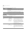
Solving Common Problems 93
Power Supply Troubleshooting 94
Related Diagnostic Procedures 95
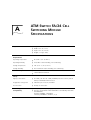
A
ATM SWITCH FA/24 CELL SWITCHING MODULE
SPECIFICATIONS
B
SAFETY INFORMATION
Bodily Harm 101
Körperliche Schäden 102
Dommages corporels 102
Equipment Damage 102
Schäden am Gerät 103
Dommage causé à l'équipement
C
103
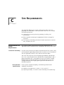
SITE REQUIREMENTS
Environmental and Safety Requirements 105
Protective Grounding 105
Environmental Specifications 105
Thermal
Recommendations 106
General Recommendations 106
Power and Heat Specifications 106
Wiring Closet Considerations 106
Distribution Rack Requirements 107
Mechanical Requirements 107
D
CABLING REQUIREMENTS
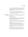
Installing New Cabling 109
Cable Labeling and Record Keeping 109
ATM Cabling 110
Caring for Fiber Optic Transceivers 111
Multi-mode Fiber Standards 112
Calculating Insertion Losses for Unlike Fibers
113
Verifying Modal Bandwidth 115
Single Mode Fiber Standards 115
Comparing Fiber to Specifications 116
Verifying Maximum Attenuation for Mixed Fibers
DS-3 Coax Cables 118
Ethernet Cabling 118
Cable Pinouts 119
E
TECHNICAL SUPPORT
Online Technical Services 123
World Wide Web Site 123
3Com Knowledgebase Web Services 123
3Com FTP Site 124
3Com Bulletin Board Service 124
3Com Facts Automated Fax Service 125
Support from Your Network Supplier 125
Support from 3Com 125
Returning Products for Repair 127
GLOSSARY
3COM CORPORATION LIMITED WARRANTY
118
ABOUT THIS GUIDE
The CoreBuilder® 7000 Family ATM Switches Installation and Startup
Guide provides all the information you need for installing and powering
up the CoreBuilder 7000 family ATM switch in ATM networking
environments. It is applicable for both the Base and Extended versions of
the software.
This guide is intended for the system administrator, network equipment
technician, or network manager who is responsible for installing and
managing network hardware such as the CoreBuilder 7000 family ATM
switch. It assumes a working knowledge of network operations and
familiarity with communications protocols that are used in networks. No
prior knowledge of 3Com’s CoreBuilder 7000 networking equipment is
necessary to understand this manual.
If the information in the release notes that are shipped with this product
differs from the information in this guide, follow the instructions in the
release notes.
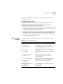
Finding Specific
Information in
This Guide
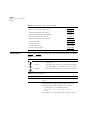
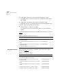
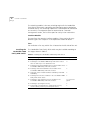
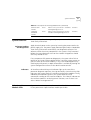
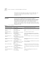
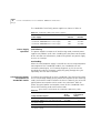
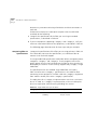
This table shows the location of specific information in this guide:
Table 1 Information in this Guide
If you are looking for
Turn to
An overview of the CoreBuilder 7000 family ATM switch and
components
Chapter 1
Instructions for unpacking the CoreBuilder 7000 family ATM
switch
Chapter 2
Information about installing your CoreBuilder 7000 family ATM
switch
Chapter 3
How to install and hot swap modules and cards and connect
cables
Chapter 4
The system power-up procedure and initial system checks
Chapter 5
10
ABOUT THIS GUIDE
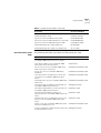
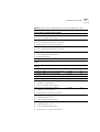
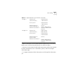
Table 1 Information in this Guide (continued)
Conventions
How to configure the CoreBuilder 7000 family ATM switch
Chapter 6
How to use the Fast Setup procedure
Chapter 6
Installing a redundant power supply
Chapter 7
Installing a redundant switching module
Chapter 7
How to troubleshoot your system
Chapter 8
Hardware and protocol specifications
Appendix A
Safety information
Appendix B
Site Requirements
Appendix C
Cabling requirements
Appendix D
Getting technical support
Appendix E
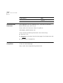
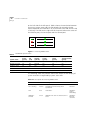
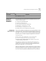
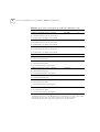
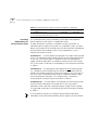
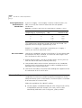
Table 2 and Table 3 list conventions that are used throughout this guide.
Table 2 Notice Icons
Icon
Notice Type
Description
Information note
Information that describes important features or
instructions
Caution
Information that alerts you to potential loss of data or
potential damage to an application, system, or device
Warning
Information that alerts you to potential personal injury
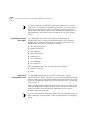
Table 3 Text Conventions
Convention
Description
Screen displays This typeface represents information as it appears on the
screen.
Syntax
The word “syntax” means that you must evaluate the syntax
provided and then supply the appropriate values for the
placeholders that appear in angle brackets. Example:
To enable RIPIP, use the following syntax:
SETDefault !<port> -RIPIP CONTrol =
Listen
In this example, you must supply a port number for <port>.
Documentation
11
Table 3 Text Conventions (continued)
Convention
Description
Commands
The word “command” means that you must enter the
command exactly as shown and then press Return or Enter.
Commands appear in bold. Example:
To remove the IP address, enter the following command:
SETDefault !0 -IP NETaddr = 0.0.0.0
The words “enter”
and “type”
When you see the word “enter” in this guide, you must type
something, and then press Return or Enter. Do not press
Return or Enter when an instruction simply says “type.”
Keyboard key names
If you must press two or more keys simultaneously, the key
names are linked with a plus sign (+). Example:
Press Ctrl+Alt+Del
Words in italics
Italics are used to:
■
■
■
Emphasize a point.
Denote a new term at the place where it is defined in the
text.
Identify menu names, menu commands, and software
button names. Examples:
From the Help menu, select Contents.
Click OK.
Documentation
CoreBuilder 7000
Family ATM Switch
Documents
This section provides information about supporting documentation,
including:
■
CoreBuilder 7000 Family ATM Switch Documents
■
Related Documents
■
Documentation Road Map
The CD-ROM that comes with your system contains on-line versions of
the documents:
■
CoreBuilder 7000 Family ATM Switches Installation and Startup
Guide
This guide describes how to install and setup a CoreBuilder 7000
family ATM switch.
12
ABOUT THIS GUIDE
■
CoreBuilder 7000 Family ATM Switches Management Guide
This guide explains how to configure the CoreBuilder 7000 family
ATM switch.
■
CoreBuilder 7000 Family ATM Switches Operations Guide
This guide contains a detailed explanation of the CoreBuilder 7000
family ATM Switch theory of operation.
■
Release Notes (on separate CD-ROM)
The release notes contain information about the latest software
release.
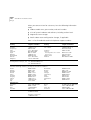
The complete documentation for the CoreBuilder 7000 family is shown in
Table 4.
.
Table 4 CoreBuilder 7000 Documentation
Document
3Com Part Number
CoreBuilder 7000 Family ATM Switches
Management Guide
DMA3700-0AAA01
CoreBuilder 7000 Family ATM Switches Operations DOA3700-0AAA01
Guide
CoreBuilder 7000 Family ATM Switches Installation DUA3700-0BAA05
and Startup Guide
CoreBuilder 7000HD Switch Release Notes
Related Documents
Documentation related to the CoreBuilder 7000 family ATM switch is
presented in Table 5.
.
Table 5 Related Documentation
Document
3Com Part Number
CoreBuilder 7200 Ethernet/ATM Interface Card
Installation and Administration Guide
DUA7200-0BAA01
CoreBuilder 7200 Ethernet/ATM Interface Card
Operation Guide
DUA7200-0AAA01
CoreBuilder 7400 Ethernet/ATM Interface Card User
Guide
DUA7400-0AAA01
CoreBuilder 7600 Fast Ethernet Interface Card User
Guide
DUA7600-0AAA01
8-Port Board ATM Interface Card User Guide
DUA3708-0AAA01
622 Mbps ATM Interface Module User Guide
DUA3762-1AAA01
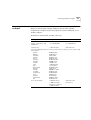
Documentation
13
Table 5 Related Documentation (continued)
Documentation Road
Map
Document
3Com Part Number
DS-3 Interface Module Installation Guide
DIA00DS-1AAA01
FastBUS Board User Guide
DUA37FB-1AAA01
SuperStack II Switch 2700 Operation Guide
DUA2700-0AAA02
SuperStack II Switch 2700 Installation & Setup Guide
DUA2700-0BAA02
SuperStack II Switch 2700 Adminstration Guide
DUA2700-OCAA02
ATMvLAN Manager User Guide (UNIX 4.22)
09-1046-002
ATMvLAN Manager User Guide ('97 Windows NT)
09-1112-001
The following table helps you locate the information you need.
If you want to...
Read...
Learn about new features or corrections in the
CoreBuilder 7000 family ATM switch software.
Release Notes
Learn about changes to the CoreBuilder 7000
family ATM switch’s documentation.
Release Notes
Get an overview of the CoreBuilder 7000 family
ATM switch system components.
Installation and Startup Guide
Prepare your site for CoreBuilder 7000 family
installation.
Installation and Startup Guide
Learn about various configurations in which you
can install your CoreBuilder 7000 family ATM
switch.
Installation and Startup Guide
Install and power up your CoreBuilder 7000 family Installation and Startup Guide
ATM switch.
Learn about how you administer and manage the
CoreBuilder 7000 family ATM switch.
Management Guide
Learn about ATM and how it is implemented in the Operations Guide
CoreBuilder 7000 family ATM switch.
Learn about LAN Emulation and how it is
implemented in the CoreBuilder 7000 family ATM
switch.
Operations Guide
Find out what type of configuration tasks you can
perform on the CoreBuilder 7000 family ATM
switch.
Operations Guide
Quickly set up your CoreBuilder 7000 family ATM
switch for management access.
Installation and Startup Guide
Perform configuration or administration tasks using Management Guide
the Administration Console.
14
ABOUT THIS GUIDE
Documentation
Comments
If you want to...
Read...
Get assistance.
Technical Support Appendix in
any guide
Your suggestions are very important to us. They help us make our
documentation more useful to you.
Please send e-mail comments about this guide to:
[email protected]
Please include the following information when commenting:
Year 2000
Compliance
■
Document Title
■
Document Part Number (found on back page of each document and
in Table 4)
■
Page Number (if appropriate)
For information on Year 2000 compliance and 3Com products, visit the
3Com Year 2000 Web page:
http://www.3com.com/products/yr2000.html
1
OVERVIEW
This chapter contains an overview of the CoreBuilder® 7000 family ATM
switches including:
■
CoreBuilder 7000 Family
■
Component Summary
■
Installing the CoreBuilder 7000 Family ATM Switch
■
Starting up the CoreBuilder 7000 Family ATM Switch
■
Redundancy in the CoreBuilder 7000 Family ATM Switch
■
Troubleshooting
For an overview of the operation of the switch, see Chapter 1 in the
Management Guide.
16
CHAPTER 1: OVERVIEW
CoreBuilder 7000
Family
The CoreBuilder 7000 family ATM switches are modular,
high-performance ATM switches designed to increase the capacity and
manageability of enterprise networks. The CoreBuilder 7000 family ATM
switches allow you to scale your network performance to extremely high
levels as your network grows and evolves. The CoreBuilder 7000 family
ATM switches include the CoreBuilder 7000 ATM switch and the
CoreBuilder 7000HD High Density ATM switch.
CoreBuilder 7000
Switch
The CoreBuilder 7000 switch includes all the features and flexibility
necessary to handle a range of needs on both the ATM backbone and the
ATM network boundary. The CoreBuilder 7000 switch provides a
backbone solution for small and medium size networks and is a modular
platform that provides a switching fabric for ATM, Ethernet/ATM and Fast
Ethernet interface cards. The 2.5 Gbps CoreBuilder 7000 switching
engine supports switched LAN interfaces in the wiring closets of large
networks, and is well suited for the backbone of small to medium-sized
networks.
CoreBuilder 7000HD
Switch
The CoreBuilder 7000HD switch supports demanding enterprise
backbones and high-density data center applications, providing
high-performance ATM switching at both the network core and
boundary. The CoreBuilder 7000HD platform features a 5.0 Gbps
switching engine that provides capacity for up to 32 non-blocking OC-3
155 ports or up to 8 non-blocking OC-12 622 Mbps ports. Using an
enhanced i960CF processor, the CoreBuilder 7000HD switch supports
faster signaling, expanded memory, and higher performance LAN
Emulation services. The switch also accommodates scalable, high density
Ethernet/ATM, Fast Ethernet and Gigabit Ethernet interface cards. The
four-slot chassis allows for a mixture of port types with versatile media
options for a wide range of network configurations.
Component Summary
Component
Summary
17
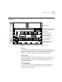
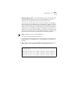
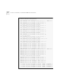
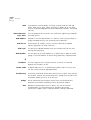
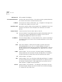
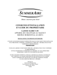
Figure 1 shows the components of the CoreBuilder 7000 family ATM
switch.
Power Supplies
TM
700 0 H D
S W IT C H
32 x 32
C oreB uilde r
700 0
PWR
10 BAS E-T
Sta tu s
FA IL
Se rvice
Sta tu s
ACT
Co ntrol
Sta tu s
M a na ge m en t
Se rvice P ort
RS2 32
RS2 32
Se rvice P ort
Co ntrol T ermi na l
RS2 32
RS2 32
700 0 H D
S W IT C H
32 x 32
1 0 Base -T
PWR
10 BAS E-T
Sta tu s
FA IL
Se rvice
Sta tu s
ACT
Co ntrol
Sta tu s
Co ntrol T ermi na l
HD
M a na ge m en t
HD
CB 7000HD Switch Module
CB7000 HD Switch Module
1 0 Base -T
5
5
8 A TM
7
Li nk S tat us
FA IL
Fa il
ACT
Act
1
P o rt Mo d u le
6
PWR
2
3
PWR
Li nk S tat us
FA IL
Fa il
ACT
Act
8
4
RX
MM
OC-3
MM
OC-3
AT M
RX
TX
RX
MM
OC-3
MM
OC-3
TX
8
RX
TX
RX
1
C
7
6
AT M
MM
OC-3
MM
OC-3
RX
TX
2
TX
MM
OC-3
MM
OC-3
TX
3
RX
TX
RX
TX
8Port Board
ATM Interface Module
4
A TM
L
F
A
CB7400 ATM/Ethernet
Interface Module
74 00 Et h/A T M
I/F Ca rd
S YS
P
F
A
A
B
A 1 - 12
B 1 3 -2 4
5
6
10 0 FX
MM
P
RX
TX
RX
TX
TX
RX
TX
RX
TX
RX
TX
1 2 3 4 5 6 7 8
TX
RX
TX
RX
TX
RX
TX
MM
RX
TX
RX
TX
RX
TX
RX
TX
10 0 FX
MM
1
10 0 FX
MM
RX
10 0 FX
MM
A
8
10 0 FX
MM
RX
10 0 FX
910111213141516
F
I/ F C ard
76 00 F as t Eth
S YS
7
10 0 FX
SYS
100 0 BA SE- SX
100 0 BASE- SX
100 0 BASE- SX
100 0 BASE- SX
1
2
3
4
78
00 Gigab
it
Eth ern et
I/ F c ard
F AIL
1
2
3
TX
CB 7600 Fast Ethernet
Interface Module
4
PWR
ACT
TX
RX
MM
3
2
RX
10 0 FX
MM
4
CB7800 Gigabit Ethernet
Interface Module
Figure 1 Components of the CoreBuilder 7000 Family ATM Switch
Enclosure
The housing for the CoreBuilder 7000 family ATM switch contains 2 slots
for switching modules and 4 slots for interface cards, 2 places for power
supplies and a ventilator fan tray. The high speed ATM switching
backplane is located inside the back of the surrounding enclosure.
Power Supply
The power supply is located at the top of the front panel. The unit is
switched on and off by connecting and disconnecting the power cord on
the face of the power supply unit. A second power supply may be
installed for redundancy.
Switching Module
The two slots just under the power supply contain switching modules,
one slot for the active switching module and the other slot for the
redundant switching module.
18
CHAPTER 1: OVERVIEW
The switching module is the core switching engine of the CoreBuilder
7000 family ATM switch, controlling and monitoring passive backplane
and ATM activity. The switching module has a control port for connection
to a terminal, a management port for connection to a network
management station, and a service port for use by 3Com technicians.
Interface Module
The next four slots contain interface modules. These can be of many
different types. See Chapter 2 in the Operations Guide for details.
Fans
For ventilation a fan tray with 6 fans is located at the left side of the unit.
Installing the
CoreBuilder 7000
Family ATM Switch
The CoreBuilder 7000 family ATM switch may be installed according to
the stages shown in Table 6.
Table 6 Installing the CoreBuilder 7000 Family ATM Switch
Installation Stage
Chapter
1 Unpacking the CoreBuilder 7000 family ATM switch
2
2 Installing the CoreBuilder 7000 family ATM switch chassis
either on table-top or in a distribution rack
4
3 Installing a main and redundant power supply module in the 5
CoreBuilder 7000 family ATM switch chassis
4 Installing a main and redundant switch module in the
CoreBuilder 7000 family ATM switch chassis
5
5 Setting up switch module hardware redundancy and LANE
redundancy
5
6 Installing 4-Port interface modules in the CoreBuilder 7000
family ATM switch chassis
5
7 Installing or replacing other interface modules in the
CoreBuilder 7000 family ATM switch chassis
See respective
guide
8 Installing or replacing the fan tray
5
9 Connecting to network devices, ATM optical interface,
control terminal, Ethernet port and power source
5
Component Summary
Starting up the
CoreBuilder 7000
Family ATM Switch
19
The CoreBuilder 7000 family ATM switch is powered on and configured
according to the stages shown in Table 7.
Table 7 Powering-on and Configuring the CoreBuilder 7000 Family ATM Switch
Stage
Chapter
1 Powering up the CoreBuilder 7000 family ATM switch
6
2 Understanding system states and switching module LEDs
6
3 Logging in to the LMA
7
4 Configuring the CoreBuilder 7000 family ATM switch by the
Integrated Fast Setup procedure
7
5 Performing additional configuration of the CoreBuilder 7000 7
family ATM switch by individual LMA commands
6 Viewing network statistics
Redundancy in the
CoreBuilder 7000
Family ATM Switch
7
The CoreBuilder 7000 family ATM switch is designed to meet the
requirements of environments where network interruptions cannot be
tolerated. The CoreBuilder 7000 family ATM switch platform has a fully
redundant design, with dual load-sharing power supplies and redundant
switching engines. All CoreBuilder 7000 family interface cards and
switching engines are hot swappable to ensure continuous operation
during configuration and servicing.
For information about determining the required power supply for various
CoreBuilder 7000 family ATM switch installations and providing
redundancy for various power loads. See “Redundant Power Supply” on
page 85.
For information about using the redundant switching module, see
Chapter 10 in the Operations Guide.
In addition to hardware redundancy, the CoreBuilder 7000 family ATM
switch also provides redundant LANE services which are managed by the
Transcend Network Management System. Each switch contains a
complete set of LES and LECS functionality. In case of failure, LANE
services can be transferred to another CoreBuilder 7000 family ATM
switch elsewhere in the network.
Troubleshooting
This guide contains a number of troubleshooting procedures for solving
common problems. For information about troubleshooting, see
Chapter 8.
20
CHAPTER 1: OVERVIEW
2
UNPACKING INSTRUCTIONS
This chapter describes how to unpack the CoreBuilder® 7000 family ATM
switch and contains the following topics:
Unpacking the
CoreBuilder 7000
Family ATM Switch
■
Unpacking the CoreBuilder 7000 Family ATM Switch.
■
Taking Inventory
Before unpacking the CoreBuilder 7000 family ATM switch, examine it
carefully for any signs of damage. After unpacking the system as
described below, you may begin the appropriate installation procedure in
Chapter 3.
If there are any visible signs of damage to the system packaging, do not
begin installation. Contact 3Com Technical Support or your distributor for
assistance.
To unpack the CoreBuilder 7000 family ATM switch, follow these
instructions:
1 Remove the clips that attach the shipping container to the shipping tray
of the packaging. The clips are located on opposite sides of the shipping
container (two per side).
2 Slowly lift the shipping container off the shipping tray. The device is now
visible.
3 Remove the accessory box and the mounting brackets from the top foam.
The mounting brackets are recessed into the foam.
4 Lift the top foam off the device.
5 Two persons are required for this step. With each person grasping the
hand-hold of the sling with one hand and holding the side of the system
with the other hand, slowly pull the device out of the foam and place it
where desired.
22
CHAPTER 2: UNPACKING INSTRUCTIONS
Save the packaging in the event that you must return the CoreBuilder
7000 Family to 3Com or your distributor.
Taking Inventory
The CoreBuilder 7000 family ATM switch package should contain the
items described in the following list. Check these items against the
packing slip. Contact 3Com Technical Support at 1-800-992-2446 if any
item is missing.
■
1 CoreBuilder 7000 family ATM switch
■
1 CD-ROM entitled 3Com Publications On Line. This CD-ROM
contains all documentation for the CoreBuilder 7000 Family ATM
Switch Software Version 4.5 and other related products
■
1 CD-ROM containing the software and Release Notes
■
1 hardware kit including:
■
■
1 pair of mounting brackets (for distribution rack installation)
■
10 screws, M4 x 8 Phillips (for mounting brackets)
■
4 rubber feet (for table installation)
■
4 screws, M4 x 8 Phillips (for rubber feet)
1 or 2 power cord(s) (2.5 meters each)
■
1 strain relief bracket per power cord
■
3 screws, M3 x 8 Phillips
Optional accessories that you ordered with your system may be shipped
separately.
Check the packing slip for other items that you ordered.
3
INSTALLING A COREBUILDER 7000
FAMILY ATM SWITCH
This chapter contains instructions for installing the CoreBuilder® 7000
family ATM switch on a table top or in a distribution rack and making the
necessary hardware connections. The topics covered in this chapter
include:
■
Safety Precautions
■
Preparation
■
Table Top Installation
■
Distribution Rack Installation
Safety Precautions
Read the following safety precautions carefully to reduce the risk of
electric shock and fire.
■
All servicing should be undertaken ONLY by qualified service
personnel. There are no user serviceable parts inside the unit.
■
The CoreBuilder 7000 family ATM switch internal power supply
provides for automatic selection of either 100-120 VAC or 200-240
VAC, 60/50 Hz, as indicated on the safety label adjacent to the power
inlet. ENSURE that the available voltage supply at the mains is within
one of these two ranges.
■
DO NOT operate the unit in a location where the maximum ambient
temperature exceeds 40 degrees C.
■
Ensure that the chassis ventilation openings in the unit are NOT
BLOCKED.
■
DO NOT plug in, turn on or attempt to operate an obviously damaged
unit.
■
Unplug the power supply cord from the wall socket BEFORE
attempting to remove and/or replace the power supply.
24
CHAPTER 3: INSTALLING A COREBUILDER 7000 FAMILY ATM SWITCH
■
The system has a redundant power supply option. Disconnecting one
power supply cord disconnects one power supply module only. To
isolate the unit completely from the mains, disconnect all power
supply cords.
Vorsichtsmaßnahm
en
Lesen Sie die folgenden Vorsichtsmaßnahmen sorgfältig, um das Risiko
von Stromschlag oder Brandgefahr zu vermindern.
■
Jede Wartung sollte NUR von befugtem Wartungspersonal
durchgeführt werden. Das Aggregat enthält keine vom Anwender zu
wartenden Teile.
■
Das interne Netzteil des CoreBuilder 7000 family ATM switch
ermöglicht automatische Wahl von 100-120 V AC oder 200-240 V
AC, 60/50 Hz, wie auf dem Sicherheitsetikett beim Netzeingang
vermerkt. VERGEWISSERN SIE SICH, daß der vom Netz gelieferte
Strom einer von diesen beiden Spannungsbereichen entspricht.
■
Nehmen Sie das Gerät NICHT in Betrieb, falls die Temperatur der
Umgebung 40 Grad C übersteigt.
■
Gehen Sie sicher, daß die Lüftungsöffnungen am Gehäuse NICHT
BLOCKIERT sind.
■
Eine offensichtlich schadhafte Einheit soll weder angeschlossen,
eingeschaltet noch in Betrieb genommen werden.
■
Ziehen Sie das Netzkabel aus Steckdose an der Wand, BEVOR Sie
versuchen, das Netzteil zu entfernen und/oder zu ersetzen.
■
Das System verfügt über ein wahlweises Ersatzstromaggregat.Das
Trennen der Verbindung eines Netzkabels unterbricht die Verbindung
nur mit einem Netzteil-Modul. Um das Gerät völlig vom Stromnetz zu
trennen, müssen alle Netzkabel gelöst werden.
Mesures de sécurité
Lire attentivement les mesures de sécurité afin de réduire les risques
d'électrocution et d'incendie.
■
Le service après-vente ne devra être effectué que par un personnel
qualifié. Aucune pièce de l'unité ne peut être réparée par le simple
utilisateur.
Preparation
Preparation
25
■
Le CoreBuilder 7000 family ATM switch d'alimentation interne permet
une sélection automatique de 100 -120 VAC ou 200-240 VAC,
60/50Hz comme stipulé sur le label de sécurité placé près de
l'ouverture d'alimentation. Veiller à ce que le voltage du secteur soit
bien compris entre les valeurs mentionnées ci-dessus.
■
Ne pas faire fonctionner l'unité dans un endroit où la température
ambiante maximale dépasse 40 degrés C.
■
Ne jamais essayer de brancher, allumer ou faire fonctionner une unité
apparemment endommagée.
■
S'assurer que les ouvertures de la ventilation du chassis de l'unité ne
sont pas bloquées.
■
Débrancher le fil d'alimentation au secteur de la prise murale AVANT
d'essayer de déplacer ou de remplacer l'unité d'alimentation.
■
Le système dispose d'un système redondant d'alimentation au secteur.
Le fait de débrancher l'une des sources d'alimentation ne débranche
que l'un des modules d'alimentation au secteur. Pour isoler
entièrement l'unité de toute alimentation, débrancher tous les câbles
d'alimentation.
Before beginning the installation procedures in this chapter, ensure that
the CoreBuilder 7000 family ATM switch is placed close to the location
where it will be installed and that the mounting brackets and hardware
kit supplied with the system are readily available. You will also need a No.
2 Phillips screwdriver.
The hardware kit contains:
Table Top
Installation
■
1 pair of mounting brackets (for distribution rack installation)
■
10 screws, M4 x 8 Phillips (for mounting brackets)
■
4 rubber feet (for table installation)
■
4 screws, M4 x 8 Phillips (for rubber feet)
The CoreBuilder 7000 family ATM switch is ready for table top installation
as shipped.
26
CHAPTER 3: INSTALLING A COREBUILDER 7000 FAMILY ATM SWITCH
To provide a firmer base for the unit, you can choose to attach four
rubber feet to the switch chassis. Use the rubber feet and the four M4 x 8
Phillips screws included in the hardware kit.
To insert the power supply, switching modules, and interface cards,
configure optical ports for the interface modules and connect network
cabling and power to the unit see Chapter 4.
Distribution Rack
Installation
You can mount the CoreBuilder 7000 family ATM switch in a 19-inch
distribution rack. This section describes how to prepare the unit and the
distribution rack, and mount the unit in the distribution rack. Please read
all of the instructions carefully before beginning the installation.
For the basic mechanical and space requirements for the distribution rack,
see “Distribution Rack Requirements” on page 107.
Unit and Rack
Preparation
To prepare the CoreBuilder 7000 family ATM switch and distribution rack
for installation:
1 Attach the mounting brackets onto the sides of the CoreBuilder 7000
family ATM switch using the mounting bracket screws (M4 x 8 Phillips).
2 Determine whether or not the distribution rack has threaded holes. If the
holes are threaded, see “Mounting the CoreBuilder 7000 Family ATM
Switch” on page 28.
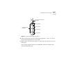
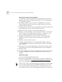
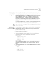
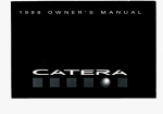
3 If the holes are not threaded, you must insert “G” clips. To determine
where to insert “G” clips, locate the top of a universal mounting hole
pattern on the left mounting rail. In the universal rail pattern, the spacing
between holes is 1/2 inch, 5/8 inch, 5/8 inch, and 1/2 inch. To find the top
of the pattern, locate the midpoint between any two holes that are
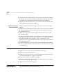
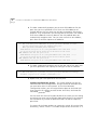
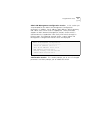
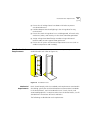
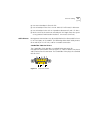
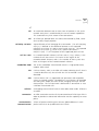
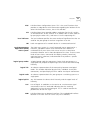
spaced half an inch apart. Figure 2 shows the universal mounting hole
pattern.
Distribution Rack Installation
27
Top of a universal mounting
hole pattern
1/2-inch spacing
Universal mounting
hole pattern
5/8-inch spacing
5/8-inch spacing
1/2-inch spacing
Figure 2 Universal Mounting Hole Pattern
4 From the top of the universal mounting hole pattern, insert “G” clips in
the holes designated for the unit model.
5 Repeat steps 3 and 4 for the right rail. Ensure that you start on the same
hole space.
You are now ready to mount the CoreBuilder 7000 family ATM switch
into the distribution rack.
28
CHAPTER 3: INSTALLING A COREBUILDER 7000 FAMILY ATM SWITCH
Mounting the
CoreBuilder 7000
Family ATM Switch
Once the distribution rack is ready, you can mount the CoreBuilder 7000
family ATM switch into the rack.
To mount the CoreBuilder 7000 family ATM switch into the distribution
rack:
1 Carefully lift the CoreBuilder 7000 family ATM switch into place, aligning
the mounting brackets to the holes you have designated for mounting.
A fully-configured CoreBuilder 7000 family ATM switch weighs 43
pounds as shipped. To avoid personal injury, do not lift the unit without
assistance.
2 While holding the CoreBuilder 7000 family ATM switch in place, firmly
insert the mounting screws (10/32 x 1/2 Phillips) into the mounting holes
on both sides of the rack.
The unit is now installed in the distribution rack.
To insert the power supply, switching modules, and interface cards,
configure optical ports for the interface modules and connect network
cabling and power to the unit see Chapter 4.
4
INSTALLING AND CONNECTING
COREBUILDER MODULES
This chapter describes how to install and replace the CoreBuilder® 7000
family modules. The following modules are covered.
■
Power Supply Module
■
Switch Module
■
4-Port Interface Module
■
Fan Tray
■
Connecting to Network Devices
The installation procedures of the other modules of the CoreBuilder 7000
family modules are described in their respective guides.
This chapter also describes how to connect the CoreBuilder 7000 family
ATM switch to network devices.
Safety Precautions
When handling replacement parts, 3Com recommends that you always
use a wrist strap connected to a proper ground. This helps prevent the
module from being damaged by electrostatic discharge. Additionally,
when not in use, the module should be stored in an antistatic bag.
If the system is powered on when you are replacing a module, do not
insert any metal objects, such as a screwdriver or a finger with jewelry, in
the open slot. This could cause burns or other bodily harm, as well as
system damage.
30
CHAPTER 4: INSTALLING AND CONNECTING C OREBUILDER M ODULES
Vorsichtsmaßnahm
en
Wenn Sie Ersatzteile handhaben, benutzen Sie immer ein Band am
Handgelenk, daß gut geerdet ist. Das hilft vermeiden, daß das Ersatzteil
durch elektrostatische Entladung beschädigt wird. Darüber hinaus sollte
ein Modul, wenn nicht benutzt, in einem antistatischen Beutel
aufbewahrt werden.
Steht das System unter Strom, wenn sie ein Modul installieren oder
auswechseln, führen Sie keine Metallgegenstände, wie einen
Schraubenzieher oder einen Finger mit Schmuck in den offenen Schlitz
ein. Das könnte zu Verbrennungen oder anderen Körperschäden führen,
sowie auch zu Schäden am System.
Mesures de sécurité
Lors de la manipulation des pièces de rechange, 3Com recommande de
toujours utiliser une bande attachée au poignet et reliée à la terre. Cela
aidera à éviter que la pièce ne soit endommagée par une décharge
électrostatique. De plus, lorsqu'il n'est pas utilisé, le module doit être
conservé dans un emballage antistatique.
Si le système est alimenté lors de l'installation ou du remplacement d'un
module, ne jamais insérer d'objet métallique tel qu'un tourne-vis ou un
doigt portant un bijou dans la fente. Cela est susceptible de provoquer
brûlures ou autres dommages corporels, et d'endommager le système.
Power Supply
Module
The CoreBuilder 7000 family ATM switch provides a dual load-sharing
power supply capability where the second unit can serve as a redundant
power supply. For more information, see “Redundant Power Supply” on
page 85.
For certain combinations of installed interface cards, the second power
supply cannot be used as a redundant supply (see “Providing Redundancy
for Various Power Loads” on page 90).
This section discusses the following topics:
■
Installing a Power Supply Module
■
Replacing a Redundant Power Supply Module
Power Supply Module
Installing a Power
Supply Module
31
To install a power supply module:
1 Orient the module so that its sides enter the guides on either side of the
chassis slot.
2 Slide the module into the chassis until the face panel is flush with the
enclosure.
3 Secure the screws on either side of the front panel.
4 If a redundant power supply is not installed in the second power supply
slot, cover the slot with a blank panel for safety.
Replacing a
Redundant Power
Supply Module
You can replace the redundant power supply without having to turn off
the system (hot-swap). For more information on the operation of the
redundant power supply module, see “Redundant Power Supply” on
page 85.
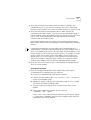
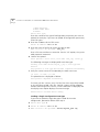
To replace a redundant power supply module:
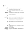
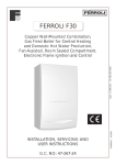
1 Disconnect the power cord from the power supply.
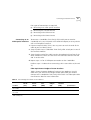
2 Loosen the screws at the extreme right and left of the power supply, near
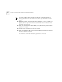
the handles (see Figure 3).
3 Grasp the handles of the redundant power supply you want to replace
and pull them outward. This ejects the power supply.
4 Remove the new power supply from its antistatic bag. Place the old
power supply in the antistatic bag and set it aside in a safe place.
5 Orient the power supply so its labelling is upright.
6 Insert the power supply into the chassis by placing it between the guides
of the slot and sliding it until it stops.
7 Tighten the power supply’s securing screws.
8 Connect the power cord to the power supply.
32
CHAPTER 4: INSTALLING AND CONNECTING C OREBUILDER M ODULES
Figure 3 Hot-Swapping a Redundant Power Supply
Switch Module
The CoreBuilder 7000 family ATM switch provides for a redundant switch
module to ensure continued operation should the main switch module
fail. For more information on the operation of the redundant switch
module, see Chapter 10 in the Operations Guide.
This section includes the following topics:
Installing a Switch
Module
■
Installing a Switch Module
■
Replacing a Switch Module
■
Setting up Switch Module Redundancy
■
Setting up Switch Module Hardware Redundancy
■
Setting up Hardware Redundancy and LANE Redundancy
To install a switch module in the CoreBuilder 7000 family ATM switch
chassis:
1 Remove the new card from its antistatic bag.
2 Orient the card so its labelling is upright and make sure the inject handles
are in the outward position.
Switch Module
33
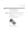
3 Insert the card into the chassis by placing it between the guides of the
selected slot and sliding the card until it stops.
4 Grab both inject handles and push them inward. This locks the card into
the chassis. You may have to apply considerable pressure to the handles.
An audible “click” indicates that the connectors have engaged.
5 Tighten the card’s securing screws. You are now ready to connect cables
to the appropriate ports.
Replacing a Switch
Module
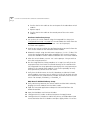
To hot-swap the switch module:
1 Disconnect the cables from the card's ports. Ensure that there is a record
of where the cables are attached so that you can correctly re-connect
them to the new card.
2 Loosen the screws at the extreme right and left of the card, near the
insert/eject handles.
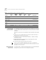
3 Grasp the insert/eject handles of the card you want to replace and push
them outward. This ejects the card. You may have to apply considerable
force to the handles. You will hear a “click” to indicate that the
connections have separated, and the card will slide slightly forward out of
the CoreBuilder chassis.
4 Remove the new card from its antistatic bag. Place the old card in the
antistatic bag and set it aside in a safe place.
5 Orient the card so its labelling is upright and make sure the inject handles
are in the outward position.
6 Insert the card into the chassis by placing it between the guides of the
selected slot and sliding the card until it stops.
7 Grab both inject handles and push them inward. This locks the card into
the chassis. You may have to apply considerable pressure to the handles.
An audible “click” indicates that the connectors have engaged. Verify
that the card has been properly installed by observing its LEDs.
8 Tighten the card’s securing screws.
9 Connect cables to the appropriate ports.
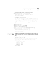
34
CHAPTER 4: INSTALLING AND CONNECTING C OREBUILDER M ODULES
Figure 4 Hot-Swapping a Switch Module or Interface Module
Setting up Switch
Module Redundancy
This section describes procedures for installing and setting up both a
main and redundant switch module together.
Two different setup procedures are described. The first procedure covers
setting up the main and redundant switch module hardware redundancy
without setting up LANE redundancy. This procedure only requires
operating the LMA. The second procedure sets up the main and
redundant switch module hardware redundancy as well as LANE
redundancy. It requires both the LMA and the Transcend Enterprise
Manager.
There are two situations where you would use the procedures of this
section:
1 The initial installation of main and redundant cards.
2 The main card in the first slot has failed and the redundant card in the
second slot has taken over as the main card. The failed card in the first
slot has been replaced by a new card and this new card is now the
redundant one.
Switch Module
Setting up Switch
Module Hardware
Redundancy
35
Use the following procedure to set up the switch module hardware
redundancy.
1 Designate and mark the main and redundant switch modules.
2 Insert the switch module you marked as “redundant” in slot 2. Do not
insert the switch module you marked as “main” yet.
3 Turn on the CoreBuilder 7000 family ATM switch.
The switch module in slot 2 becomes active.
4 Run the Integrated Fast Setup procedure (see “Integrated Fast Setup” on
page 56.) using the LMA command
(9) FST
5 Insert the main switch module in slot 1.
6 Reboot the CoreBuilder 7000 family ATM switch using the LMA menu
sequence:
(1) SYS / (7) RBO.
The switch module in slot 1 becomes active.
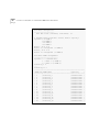
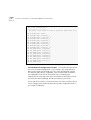
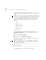
7 Verify main and redundant switch module status using the LMA
command:
(1) SYS / (4) SWM
You should see the following display.
Slot id
Slot status
-------
1
2
Switch type
-----------
Occupied
Occupied
Switch mode
----------------
16x16 ATM switch
16x16 ATM switch
Memory size
------------
Active
Redundant
-----------
8M
8M
8 Run the Integrated Fast Setup procedure using the LMA command
(9) FST to verify the configuration in the main switch module.
The switch is now operational.
Setting up Hardware
Redundancy and
LANE Redundancy
This section presents a procedure for setting up both switch module
hardware redundancy and LANE redundancy in the same session. Both
the LMA and the Transcend Enterprise Manager are used.
36
CHAPTER 4: INSTALLING AND CONNECTING C OREBUILDER M ODULES
General Description of the Procedure
The following is a general description of the procedure for orientation
purposes only. When you perform the procedure, use the detailed steps
in the following sections.
1 Install both switches in chassis and run CFGFRMAT.BAT on each one.
Connect Ethernet ports of each switch module and install at least one
interface card in the chassis.
2 Configure the first switch using the Integrated Fast Setup of the LMA and
do not reboot the switch in the Integrated Fast Setup.
3 Reboot the switch after one minute using the LMA menu.
4 Answer “no” to the prompt “Erase the setup parameters?” and use the
LMA to check that all configuration parameters (i.e., database, IP, NNI
etc.) have passed successfully to the second switch module.
5 Configure LANE redundancy in the first switch using the Transcend
Backbone and Services Setup window and close the window when
finished.
6 Reboot the switch after one minute
7 Configure LANE redundancy in the second switch module using the
Transcend Backbone and Services Setup window and close the window
when finished.
8 After one minute use the MIB browser to check the LECS order list and
the Backbone and Services Setup window to check the LECS database.
9 Reboot the box.
10 Check the second switch using the MIB browser to check the LECS order
list and the Backbone and Services Setup window to check the LECS
database.
Preparatory Steps
Carry out the following preparatory steps.
1 Install main and redundant switch modules in the switch module slot 1
and slot 2 respectively (see“Installing a Switch Module” on page 32). Do
not run the Integrated Fast Setup yet.
Each time the switch is rebooted during this procedure the cards change
roles. The main card becomes the redundant card and vice versa. The
main card can always be identified by its ACT LED flashing once every
two seconds. The ACT LED of the redundant card flashes at a lower rate.
Switch Module
37
2 Verify that at least one interface card of any type is installed in the
CoreBuilder chassis in any interface card slots 3-6. Data is transferred
between switch modules via a communications chip on an interface card.
3 Verify that the Ethernet management ports in both switches are
connected to the NMS station. They can either be connected through a
hub to the NMS station or through an Ethernet interface card in the same
chassis, such as the CoreBuilder 7400 High Density Ethernet/ATM
interface card, to the NMS station.
During the procedure you will need to verify connectivity between the
NMS station and the switch by pinging the switch module from the NMS
station.
Connectivity between the switch module and its attached devices is
established by a coldStart trap transmitted by the switch module when it
boots. The coldStart trap causes a device to learn the MAC address of the
switch module. However, there are certain devices, for example, a Solaris
station, which will not learn a new MAC address for an IP when one
already exists. If you are using one of these devices as an NMS station,
and you are unable to ping the switch module, try erasing the switch
module’s MAC address from the device’s ARP table and ping again.
4 Verify that the RS-232 terminal line is connected to the console port on
the main switch module.
Procedure Execution
1 Reset the configuration of both switch modules by executing the
CFGFRMAT.BAT file supplied with your software.
To execute the CFGFRMAT.BAT file proceed as follows:
a Perform the LMA command (1) SYS / (3) LOA / (3) LCL / 1 to put the
system in Load Mode: Load.
b Reboot the switch using the LMA menu command: (1) SYS / (7) RBO.
The switch will reboot in debug mode.
c Transfer the RS-232 cable to the service port of the main switch
module.
d From a DOS window on the LMA terminal execute
> cfgfrmat com
speed
where “com” is the communications port you are using and “speed”
is 115200 for a CoreBuilder 7000HD switch module and 57600 for a
CoreBuilder 7000 switch module.
38
CHAPTER 4: INSTALLING AND CONNECTING C OREBUILDER M ODULES
e Transfer the RS-232 cable to the service port of the redundant switch
module.
f
Repeat step d)
g Transfer the RS-232 cable to the console port of the main switch
module.
Hardware Redundancy Setup
2 Set up the main switch module using the Integrated Fast Setup (see
“Integrated Fast Setup” on page 56). Do not reboot the switch from the
Integrated Fast Setup procedure (answer “no” to the prompt).
The main menu appears.
3 Wait for one minute to allow the configuration data to transfer from the
main switch module to the redundant switch module.
4 Reboot the switch using the LMA menu sequence: (1) SYS / (7) RBO. This
causes the configuration data to be recorded in flash memory and also
causes the redundant switch module to become the main switch module.
5 After the switch reboots, answer “no” to the prompt: “Do you wish to
erase the setup parameters”.
6 Run the Integrated Fast Setup procedure as in step 2) to verify that the
setup parameters have been transferred correctly to the second switch
(the Integrated Fast Setup procedure now displays the setup parameters
resident in the second switch module). Press Enter repeatedly to verify
these parameters; do not enter new values.
7 Verify that the ELAN names in the LECS database are identical in both
switch modules. Use menu item (2) LEM/(1) LCS/(5) LNT to check that the
LECS database of the second switch includes the ELAN name of the first
switch. For example, Elan6666_0 - Elan6666_15
NMS-Based LANE Redundancy Setup
8 Verify connectivity between the switch module and the NMS station by
pinging the switch module from the NMS station.
9 Load the Transcend application and open the Wizard Tool from the
ATMvLAN tool bar
10 Open the Backbone and Services Window.
11 Configure the LECS order as desired and press the Apply button.
12 Configure the LECS database. Add all the primary and redundant ELAN
names desired to the LECS database and press Apply. Make a list of the
Switch Module
39
ELAN names you have selected. You will need them for setting up the
other switch module.
13 When finished, close the Backbone and Services window.
14 Wait one minute to allow the LECS order database to transfer to the
other switch module.
The LECS ELAN database does not transfer automatically.
15 Reboot the switch using the LMA menu sequence: (1) SYS / (7) RBO.
The purpose of this step is to make the first switch module active in order
to set up the LANE services there.
16 After the first switch boots, check its connectivity with the NMS station as
in step 8).
17 Perform steps 10) and 12) using the same list of ELANs.
18 Wait one minute.
Verifying LANE Redundancy Setup
19 Use the MIB browser under the Transcend tools menu and browse
through the MIB to verify that all the information regarding the LECS
order list has been transferred correctly.
Look in the following MIB location:
■
private
■
enterprises
■
atmForum
■
atmForumNetworkManagement
■
atmLanEmulation
■
elanMIB
■
elanLecsGroup
■
elanLecsConfGrou.
■
lecsConfTablelecsConfEntry
■
lecsAtmAddrSpec
Press start query. The LECS order list is displayed on the bottom window.
20 Close the Backbone and Services Select window.
21 Open the Backbone and Services Select window again and use it to check
that the LECS database is correct.
40
CHAPTER 4: INSTALLING AND CONNECTING C OREBUILDER M ODULES
This item could be done through the LMA but it is preferred to do so
through the NMS since the LMA will not show any redundant LES that
exists.
22 Reboot the switch using the LMA menu sequence: (1) SYS / (7) RBO. The
purpose of this step is to make the second card active in order to check
the LANE services there.
23 After the second switch module boots, verify connectivity with the NMS
station as in step 8).
24 Perform step 19) and 20) to verify LECS order.
25 Open the Backbone and Services Select window again and use it to check
the LECS database is correct.
The hardware and LANE redundancy procedure is finished.
4-Port Interface Module
4-Port Interface
Module
ATM Interface
Daughter Cards
41
This section contains the following topics:
■
ATM Interface Daughter Cards
■
Installing the ATM Interface Daughter Cards
■
Installing a 4-Port Interface Module
■
Replacing a 4-Port Interface Module
Each of the four ATM interface receptacles of the 4-Port ATM Interface
module can be configured to support the following types of ATM
daughter cards:
■
OC-3 multi-mode (MM) fiber link, single-mode (SM) fiber link
■
DS-3 coaxial cable
■
E-3 ATM 34.368 Mbits/sec WAN interface
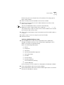
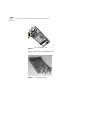
Figure 5 shows the OC-3 daughter card.
Figure 5 OC-3 Daughter Card
Figure 6 shows the DS-3 daughter card.
42
CHAPTER 4: INSTALLING AND CONNECTING C OREBUILDER M ODULES
Figure 6 DS-3 Daughter Card
Figure 7 shows the E-3 daughter card.
Figure 7 E-3 Daughter Card
4-Port Interface Module
Installing the ATM
Interface Daughter
Cards
43
The 4-port ATM interface module can hold up to four ATM interface
daughter cards. The installation procedure of the 4-port ATM interface
module comprises two stages. First, you install the ATM interface
daughter cards in the 4-port ATM interface module. Then, you install the
4-port ATM interface module into the CoreBuilder 7000 family ATM
switch chassis.
To install the ATM interface daughter cards perform the following
procedure:
1 Select the individual daughter cards that are to occupy the interface card’s
four openings.
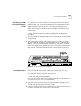
2 Align each module with the front panel aperture as shown in Figure 8
and press down to engage the strip connectors on the underside of the
module. Three screws anchor each module to its seat on the interface
card. Interface openings reserved for future use should be covered with
blank panels. Used interfaces should use the coax or optical panels as
covers.
Figure 8 4-Port ATM Interface Module
Installing a 4-Port
Interface Module
When the ports of the interface module have been fitted with the
appropriate daughter card, you install the 4-port interface module into
the CoreBuilder 7000 family ATM switch chassis.
To install the 4-port interface module:
1 Orient the interface module so its labelling is upright and be certain that
the inject handles are in the outward position.
2 Insert the card into the chassis by placing it between the guides of the
selected slot and sliding the card until it stops.
3 Be certain that the card sits in the guide slots on either side. Be sure that
the loose screws do not interfere with card insertion.
44
CHAPTER 4: INSTALLING AND CONNECTING C OREBUILDER M ODULES
4 Grab both inject handles and push them inward. This locks the card into
the chassis. You may have to apply considerable pressure to the handles.
An audible “click” indicates that the connectors have engaged.
5 Tighten the card’s securing screws. You are now ready to connect cables
to the appropriate ports of the module.
Replacing a 4-Port
Interface Module
To replace individual daughter cards, or to replace the entire interface
module:
1 Disconnect the cables from the card's ports. Ensure that there is a record
of where the cables are attached so that you can correctly re-connect
them to the new card.
2 Loosen the screws at the extreme right and left of the card, near the
insert/eject handles.
3 Grasp the insert/eject handles of the card you want to replace and push
them outward. This ejects the card. You may have to apply considerable
force to the handles. You will hear a “click” to indicate that the
connections have separated, and the card will slide slightly forward out of
the CoreBuilder chassis.
4 If you are replacing the entire interface card, remove the new card from
its anti-static bag. Place the old card in the anti-static bag and set it aside
in a safe place.
Fan Tray
To replace the fan tray:
1 Loosen the screws at the top and bottom of the fan tray.
2 Pull the fan tray out of the chassis.
3 Remove the new fan tray from its antistatic bag. Place the old fan tray in
the antistatic bag and set it aside in a safe place.
4 Orient the fan tray so its labelling is upright.
5 Insert the new fan tray into the chassis by placing it between the guides
of the slot and sliding it until it stops.
6 Tighten the fan tray’s securing screws.
Connecting to
Network Devices
This section describes how to connect the CoreBuilder 7000 family ATM
switch to different types of network devices.
Connecting to Network Devices
45
Four types of connections are required:
■
Connecting to an ATM Optical Interface
■
Connecting the Control Terminal
■
Connecting to the Ethernet Port
■
Connecting to the Power Source
To connect a CoreBuilder 7000 family ATM switch port to another
CoreBuilder unit, to a LinkSwitch 2700 ATMLink adapter, or to any device
with an ATM optical interface:
Connecting to an
ATM Optical Interface
1 Prepare an optical cable (Tx Rx). You may want to mark the ends of the
cable so you can identify them.
2 Snap the cable into a CoreBuilder 7000 family ATM switch port in one of
the interface modules.
3 Snap the other end of the cable into the selected optical interface of the
other ATM device. Make sure that each wire connects to Rx on one end
and Tx on the other.
4 Repeat steps 1-3 for all ATM port connections to the CoreBuilder.
Perform steps 1-4 above when connecting a DS-3 coax cable set (Rx and
Tx).
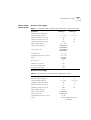
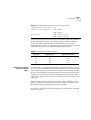
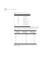
Fiber Optic Power Budget of 3Com Products
Table 8 shows the power budget of various 3Com products. Use this
table when you calculate the length of fiber optic cable you need to
connect to the CoreBuilder 7000 family ATM switch. See fiber optic cable
manufacturers data for more information.
.
Table 8 Power Budget for Various 3Com Products
Mode
(nm)
Min TX.
O-Pwr
(dBM)
Receiver
Sens.
(dBM)
Budget
(dB)
Distance
(KM)
Specification
4-Port/8-Port
OC-3 MM
MM-1300
-19
-30
11
2
HP#:HFBR-5205
4-Port/8-Port
OC-3 SM
SM-1300
-15
-33
18
15
SDX-1155B
-19
-30
11
2
HP#:HFBR-5205
Product
CoreBuilder
MM-1300
7201 (ATM port)
CHAPTER 4: INSTALLING AND CONNECTING C OREBUILDER M ODULES
46
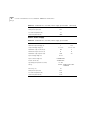
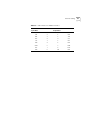
Table 8 Power Budget for Various 3Com Products (continued)
Min TX.
O-Pwr
(dBM)
Receiver
Sens.
(dBM)
Budget
(dB)
Distance
(KM)
Specification
CoreBuilder
SM-1300
7201 (ATM port)
-15
-33
18
15
SDX-1155B
CoreBuilder
MM-820
7200F - Ethernet
-7.6
-15.1
7.5
HP#:HFBR-2416TC
HP#:HFBR-1414T
CoreBuilder
SM
7200F - Ethernet
N/A
CoreBuilder
7600FX
MM-1300
-19
-31
12
HP#:HFBR-5103
CoreBuilder
7600FX
SM
N/A
OC-12
MM-1300
-19
-26
7
0.8
HP#:HFBR-5208
OC-12
SM
-15
-28
13
15
HP#:SDX-1622
Product
Mode
(nm)
Connecting the
Control Terminal
The CoreBuilder 7000 family ATM switch can be configured via the LMA
using the Administration Console terminal (VT100) or terminal emulator
(Windows).
To connect a terminal to the CoreBuilder 7000 family ATM switch control
port:
1 Prepare an RS-232 shielded cable (9 pin-to-9 pin or 9 pin-to-25 pin, as
dictated by the terminal you wish to use).
2 Configure the terminal: 19200 baud, 8 data bits, 1 stop bit, no parity,
xon/xoff flow control.
3 Push the DCE side of the cable onto the Control port of the switch
module and screw it into place.
4 Connect the other end of the cable to the terminal.
In case you have installed a redundant switch unit, it is sufficient to
connect the RS-232 line to either the active switch control port or to the
redundant switch control port.
Connecting to the
Ethernet Port
The Ethernet port is used for connecting directly to a Transcend Network
Management System terminal for management purposes.
Connecting to Network Devices
47
In case you have installed a redundant switch module, its Ethernet port
must also be connected directly to the Transcend NMS terminal.
Another way of connecting the Ethernet port to an out-of-band Ethernet
network is to connect it to a CoreBuilder 7200 Ethernet/ATM Interface
Card or a CB7400 High Density Ethernet/ATM Interface Card installed in
the same chassis.
Connecting to the
Power Source
This section describes how to connect the CoreBuilder 7000 family ATM
switch to the power source.
Selecting a Power Cord
The following power cords and accessories are supplied with the unit:
■
1 or 2 power cord(s) (2.5 meters each)
■
1 strain relief bracket per power cord
■
3 screws, M3 x 8 Phillips
The power cord supplied with the unit can be used with loads of up to 5
Amps AC.
If power cord(s) WERE NOT supplied with the unit, choose a cord based
on the following information:
■
For units installed in the USA or Canada: Select a flexible,
three-conductor power cord that is UL-listed and CSA-certified, with
individual conductor wire size of #18 AWG, and with a maximum
length of 4.5 meters. The power cord terminations should be NEMA
Type 5-15P (three-prong earthing) at one end and IEC appliance inlet
coupler at the other end.
■
The following types are acceptable: SV, SVE, SVO, SVT, SVTO, SVTOO,
S, SE, SO, SOO, ST, STO, STOO, SJ, SJE, SJO, SJOO, SJT, SJTOO, SP-3,
SPE-3, SPT-3, G, W.
■
For units installed in all other countries, select only a flexible,
three-conductor power cord, approved by the cognizant safety
organization of your country. The power cord must be of the type HAR
(Harmonized), with an individual conductor wire size of 0.75 sq.mm.
The power cord terminations should be a suitably-rated earthing-type
plug at one end and an IEC appliance inlet coupler at the other end.
Both of the power cord terminations must carry the certification label
(mark) of the cognizant safety organization of your country.
48
CHAPTER 4: INSTALLING AND CONNECTING C OREBUILDER M ODULES
Plugging in the Unit
To plug in the unit:
1 Plug the power cord into the power source.
2 Plug the other end of the cord into the AC inlet located in the topmost
section of the CoreBuilder 7000 family ATM switch front panel. Make
sure the power cord is fully seated. A green power LED on the power
supply should be lit. The unit is automatically powered up when the
power cord is plugged in.
3 Be certain that the fans are working. If the fans are not working, unplug
the unit immediately and see “Fans do not rotate” on page 94.
5
POWER-ON
This chapter describes the system states of the CoreBuilder® 7000 family
ATM switch including power-on and some basic diagnostic information to
help you verify normal operation of your CoreBuilder system.
This chapter describes the following topics:
System States
■
System States
■
System Power-on
■
4-Port Interface Module LEDs
This section describes the different system states of the 8-Port Board and
how they are indicated on the LED display.
The system states are:
System States and
Switching Module
LEDs
■
Power-on
■
Normal operation
■
Hardware fault
■
Software fault
■
No power to unit
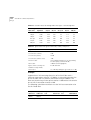
LED indicators are located on the front panels of the CoreBuilder 7000, its
power supply, switching modules, and interface modules. These LEDs
indicate the current system state of the CoreBuilder unit and its
components. Front panel LEDs can be extremely useful in determining the
cause of specific problems.
The system state in which the CoreBuilder 7000 unit is currently
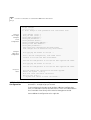
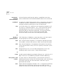
operating is displayed by the switching module system status LEDs.
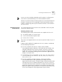
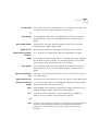
Referring to Figure 9, these are the three LEDs: PWR, FAIL, and ACT(ive)
50
CHAPTER 5: POWER-ON
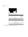
on the left side of the LED panel. Table 9 shows the correlation between
the current system state and SYS LEDs display. For example, during
normal operation the PWR LED is on, the FAIL LED is off and the ACT LED
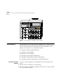
is flashing. The LEDs on the right side of the panel indicate the status of
the Ethernet port, the Service port and the Control port.
PWR
10BASE-T
Status
FAIL
Service
Status
ACT
Control
Status
Figure 9 Switching Module LEDs
Table 9 CoreBuilder System States
System State
Power
(green)
Fail
(red)
Activity
(yellow)
10BASE-T
Status
(green)
Service Port
Status
(green)
Control
Terminal Status
(green)
Power-on
On
Off
On
On
Flashing
Flashing
Normal operation
On
Off
Flashing
On
On
On
Hardware fault
On
On
Off
Off
Off
Off
Software fault
On
Off
Not flashing Undetermined Undetermined Undetermined
No power to unit
Off
Off
Off
Off
Off
Off
The following table also provides information about the LED display of
system states but is organized by system status LED.
Table 10 Description of Switching Module LEDs
LED
Color
Description
Source
PWR (Power)
Green
DC power input active.
Hardware
ACT (Activity)
Yellow
Should blink continuously when
operational.
Software
FAIL
Red
CPU failure.
Hardware
CPU or
Watchdog
10BASE-T
STATUS
Green
10BASE-T link OK. The Ethernet link is
active.
Hardware
Ethernet
controller
System Power-on
51
Table 10 Description of Switching Module LEDs (continued)
System Power-on
Software Loading
and Diagnostics
SERVICE PORT
STATUS
Green
RS232 service port link OK – should be
blinking during power on.
Software
CONTROL
TERMINAL
STATUS
Green
RS232 control terminal port link OK –
should be blinking during power on.
Software
This section describes the stages of system power-on of the CoreBuilder
7000 family ATM switch.
Apply electrical power to the system by inserting the power cord in the
power supply unit. The power supply indicator lights and the CoreBuilder
7000 family ATM switch automatically runs diagnostic software. This
software verifies that every component in the system is fully functional
before the system becomes active on the network. Diagnostics should
take sixty seconds or less.
If any component fails power-on diagnostics, the system either fails to
power on or it keeps faulty modules off-line. Once the system comes up,
you can check to see which modules, if any, have failed diagnostics by
checking the LED panels; in-depth information is available by viewing the
system configuration screens on the administration console.
Indicators
4-Port Interface
Module LEDs
All interface and switching unit indicators light at the start of the
power-on diagnostic sequence, then go out briefly. General activity LEDs
light up as the system checks the switching and interface modules. Finally,
individual port indicators go on as the system discovers active
connections residing on the interface modules. The 10BaseT indicator on
the interface module is on during normal function, even if there is no
active 10BaseT management link.
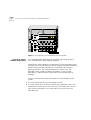
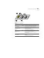
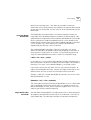
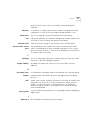
Figure 10 shows the 4-port interface module LEDs. Table 11 and Table 12
list the permanent 4-port interface module panel LEDs.
52
CHAPTER 5: POWER-ON
Figure 10 Interface Module LEDs
Table 11 Description of Interface Module LEDs
LED
Color
Description
Source
PWR (Power)
Green
DC power input active.
Hardware
FAIL
Red
CPU failure.
Hardware
CPU or
Watchdog
ACT (Activity)
Yellow
Should blink continuously when
operational.
Software
Table 12 Description of Interface Module LEDs for Each Port
DS-3 Status LEDs
LED
Color
Description
Source
LINK STATUS
Green
ATM physical layer is connected and
has no error.
Software
FAIL
Red
ATM interface port test failure.
Software
ACT (Activity)
Yellow
Reception and transmission of cells on
ATM link – should flash to indicate
traffic.
Software
The DS-3 status LEDs are found on the front panel of the DS-3 piggy.
Table 13 lists the LEDs of the DS-3 piggy.
4-Port Interface Module LEDs
53
Figure 11 DS-3 Status LEDs
Table 13 DS-3 Status LEDs
LED
Color
Description
LOS
Loss of Signal
Green
On: There is a signal on Rx (normal state).
FERF
Far End Rx Failure
Signal
Yellow
AIS
Alarm Indication
Signal
Blue
LOF
Loss of Frame
Red
Off: No signal on Rx (problem with Rx).
On: FERF in incoming frames (the peer reports
about its Rx problem).
Off: No FERF in incoming frame.
On: AIS signal is present for at least 5 sec. (the
peer reports about its problem).
Off: No AIS signal present for at least 5 sec.
(normal state).
On: LOF is present for at least 5 sec. (problems
with Rx).
Off: No LOF for at least 15 sec.
54
CHAPTER 5: POWER-ON
6
CONFIGURING THE
COREBUILDER 7000 FAMILY ATM
SWITCH
This chapter describes the initial configuration of the CoreBuilder® 7000
family ATM switch. Using the terminal connected to the control port, you
log into the system and assign network addresses to the CoreBuilder
7000 family ATM switch. This procedure enables the management of the
site to recognize and communicate with the CoreBuilder 7000 family
ATM switch. You also specify ATM connections between addresses, using
the ATM protocol you have selected.
The topics covered in this chapter include:
Logging in to the
LMA
■
Logging in to the LMA
■
Integrated Fast Setup
■
Additional Switch Configuration
■
Viewing Network Statistics.
■
Storing and Retrieving Configuration Parameters
■
Upgrading from E-IISP to PNNI
When you boot the CoreBuilder 7000 family ATM switch the following
login screen appears:
------------------------------CoreBuilder 7000
- ATM
Backbone
Switch ------------------------------Access level (read, write, admin):admin
Password:
56
CHAPTER 6: CONFIGURING THE COREBUILDER 7000 FAMILY ATM SWITCH
To log in to the LMA:
1 Enter your access level (default is admin)
2 Enter your password
After a successful login the LMA Main Menu is displayed as shown in
Figure 12.
CB7000 switch module - Main Menu:
==========
(1) SYS: Platform config ->
(2) LEM: Lan Emulation ->
(3) CON: Connections ->
(4) STS: Statistics ->
(5) DIA: Testing & Diagnostics ->
(6) FTR: ATM features
(7) LOG: Logout
(8) VER: Version
(9) FST: Fast Setup
Figure 12 LMA Main Menu
Integrated Fast
Setup
This section describes the Integrated Fast Setup procedure and contains
the following topics:
■
Setup Modes
■
Setup Procedure Sections
■
Entering Data
■
Navigation Aids
■
Integrated Fast Setup Operation
Use the Integrated Fast Setup procedure to configure the minimum set of
parameters needed to enable the CoreBuilder 7000 family ATM switch
and its attached devices to function in the network.
With this procedure you can configure both the CoreBuilder 7000 family
ATM switch card and all CoreBuilder 7X00 interface cards installed in it in
one session.
Integrated Fast Setup
57
In certain cases you will need to use the Fast Setup procedure of
individual CoreBuilder 7X00 interface cards, in addition to the Integrated
Fast Setup procedure, to correctly configure your system.
This section presents the Integrated Fast Setup of the CoreBuilder 7000
family ATM switch card. It also explains when to use the Integrated Fast
Setup of the CoreBuilder 7000 family ATM switch card and when to use
the Fast Setup of an individual Corebuilder 7X00 interface card. For
detailed information about how to use the Fast Setup of an individual
Corebuilder 7X00 interface card, see the User Guide of the specific
interface card.
Chassis-oriented Setup
The Integrated Fast Setup procedure is based on the concept that the
CoreBuilder 7000 family ATM switch chassis together with its installed
interface cards is viewed as an integrated unit. The advantage of this
point of view is its simplicity: it is not necessary to remember in which slot
each interface card is installed or even which type of interface card is
installed. Attention is focussed on configuring the ports of the chassis.
The procedure automatically determines the ports that are available in the
chassis and presents them by type (Ethernet, Fast Ethernet, ATM) for
configuration. The port location is displayed by the notation <slot.port>.
For example <3.1> refers to slot #3, port #1.
Chassis-wide VLANs
With the Integrated Fast Setup, Virtual LANs (VLANs) can be created
across the entire chassis. VLANs are set up in two stages. First, in the LE
Client section, a number of potential VLANs are created according to the
requirement of the network. Next, in the Virtual Network Configuration
section, the potential VLANs become actual VLANs by having ports
assigned to them.
You need to define an administration “admin” VLAN to maintain SNMP
connectivity to each device in the network. Using the Integrated Fast
Setup you define one admin VLAN for the chassis; there is no need to
define separate admin VLANs for each interface card.
Note that from software version 3.5 on, the “admin” VLAN can now be
called by any other name providing the same name is used consistently in
the CB7000 and in all installed CB7X00 interface cards. When using the
Integrated Fast Setup, the name for the admin VLAN which is specified
for the switch module will be automatically chosen for the other modules
58
CHAPTER 6: CONFIGURING THE COREBUILDER 7000 FAMILY ATM SWITCH
housed in the same CoreBuilder 7000 family ATM switch chassis,
overriding any existing admin VLAN names.
Setup Modes
The Integrated Fast Setup provides two setup modes: the “Full” setup
mode and the “Switch” setup mode.
Full Setup Mode
The Full setup mode configures both the CoreBuilder 7000 family ATM
switch and the installed interface cards. It sets the required parameter
values in all the installed interface cards. The Full setup mode presents
only the most critical parameters; default values are assumed for the
remaining parameters.
This method is recommended for most users, especially for initial setup.
Only those systems that require specific parameter settings in one or
more of the installed interface cards will require the Switch setup mode
described in the next section.
Switch Setup Mode
The Switch setup mode focuses only on the CoreBuilder 7000 family ATM
switch and its ATM ports. The Switch setup mode allows you to retain
special settings in the interface cards. In this mode, the installed interface
card configurations cannot be changed. If you want to alter the settings
in an interface card, use the Fast Setup of that interface card after you are
finished using the Switch setup procedure.
Setup Mode Selection
If one of the following conditions is detected, the operator is prompted
to choose between the Switch and Full setup modes:
■
A Subnet Mask, Default Gateway or NMS Address different from that
of the CoreBuilder 7000 family ATM switch
■
A VLAN whose ATM connection is set to “No”
■
The name of the ELAN to which the default admin port (Port #1 in
each slot) is attached is not the same in all interface cards.
If none of these situations is detected, Full setup mode is automatically
selected.
Integrated Fast Setup
59
If Full setup is selected, the parameters in the interface cards revert to
their default values.
Setting Special Parameters
If one or more individual interface cards requires one of the special
situations referred to in the previous section or needs to remain
unaltered, you need to do one of the following:
Setup Procedure
Sections
■
Use the Switch setup mode of the Integrated Fast Setup to set up the
CoreBuilder 7000 family ATM switch only and then use the Fast Setup
of each installed interface card separately.
■
Use the Full setup mode of the Integrated Fast Setup to configure the
CoreBuilder 7000 family ATM switch and all installed interface cards
and then use the Fast Setup for the particular interface card in order to
restore its special parameter values.
The Integrated Fast Setup procedure contains the following sections:
Table 14 Setup Procedure Sections
Setup Section
Description
1 Routing Mode
Set the Routing Protocol to be used
2 Network Prefix
Set Network Prefix for CoreBuilder 7000
3 PNNI Parameter
Set the PNNI node level (for the PNNI protocol —
Version 4.5 extended only)
4 LE Parameters
Set LE Parameters for CoreBuilder 7000 (LECS
and LES states)
5 LECS Address
Set resident active LECS address for CoreBuilder
7000
6 FastBUS Configuration
Configure the FastBUS card if installed.
7 Interface Type
Set the interface type port parameters for
CoreBuilder 7000
8 LE Client Configuration
Define potential VLANs by assigning names to
ELANs. Exit this section by pressing Enter only.
9 Virtual Network
Configuration
Assign chassis ports to potential VLANs.
10 Admin VN Management
Configuration
Set up admin VLAN in all modules including
setting IP address
11 Confirmation
Confirm setup
60
CHAPTER 6: CONFIGURING THE COREBUILDER 7000 FAMILY ATM SWITCH
Entering Data
The Integrated Fast Setup procedure runs sequentially through the
relevant data for all of the sections, displaying a prompt for each data
item and a default value. If you want to change the default, enter the
desired value in place of the default. If you want to accept the default,
press Enter.
Default Parameter Values
The default parameter value displayed at the prompt is the value stored in
flash memory. In case there is no value in flash memory, the factory
default value is displayed.
Navigation Aids
Table 15 lists the short-cut characters you can use to move between
sections of the Integrated Fast Setup procedure:
Table 15 Integrated Fast Setup Procedure Navigation Aids
Integrated Fast Setup
Operation
Type:
To Go:
<
Back to previous section
>
To next section
>S
To section indicated by double-underlined identifier letter S in section
title
\
Back to beginning of setup
$
To end of setup
You initiate the Integrated Fast Setup from the LMA Main Menu of the
Corebuilder 7000 family ATM switch (see Figure 12).
To begin the Integrated Fast Setup process, select the menu item:
(9) FST: Fast Setup
Note that the Integrated Fast Setup “Full” setup mode may override any
specific configurations that have previously been carried out in any of the
installed interface cards (see “Setup Modes” on page 58). The following
warning message is displayed when this is about to occur:
***Note: Full fast setup, special module configuration will
be overridden.
The following message appears on the screen.
Integrated Fast Setup
61
Now reading the modules configuration, please wait ...
Special module configuration will be overridden by fast setup.
continue full fast setup or only switch fast setup (S<witch>, F<ull>): F
***Note: Full fast setup, special module configuration will be overridden.
Fast Setup Utility
==================
The flash configuration will be displayed below;
Update if needed, and then hit Enter.
To move between sections, enter the following characters at end of line:
< > - Back and forth in sections
>S
- Jump to section ID S
\
- Back to beginning of setup
$
- To end of setup
Only
}G
*
.T
in
-
Virtual Network Configuration section (group=slot; item=port):
Jump to group #G
+I
- Jump to item #I
Update all group items
**
- Update all section items
Assign a VLT tag #T
Routing Mode Section In this section you are prompted to select
PNNI or E-IISP as the routing protocol to be used. Enter 1 for PNNI or 0 for
E-IISP.
Routing mode
=----------Select routing mode (1-PNNI, 0- E-IISP) : 1
PNNI is available in version 4.5 extended only.
Network Prefix Section In this section you are prompted for the
network prefix of the switch. Enter values as appropriate. The following
example shows a typical network prefix setting.
62
CHAPTER 6: CONFIGURING THE COREBUILDER 7000 FAMILY ATM SWITCH
Network Prefix
=------------Network Prefix(In HEX): 47.00.00.00.00.00.3c.00.00.a*
PNNI Parameter Section If PNNI was selected as the routing mode, in
this section you are prompted to enter the PNNI node level, i.e., the
hierarchy level of the peer group to which it the node belongs. Enter a
value in the range 0 to 104.
PNNI Parameters
=-------------Enter PNNI Node Level [0 to 104]: 72
LE Parameters Section In this section you are prompted to enable or
disable the resident LECS and LES of the switch. Enter values as follows:
1 At the “Resident LECS state” prompt, enter 1 to enable the resident LECS
or enter 0 to disable the resident LECS.
If you enter 1, the resident LES will be enabled automatically and no
further prompt will be displayed. If you enter 0, the “LES state” prompt
will be displayed.
2 At the “LES state” prompt, enter 1 to enable the resident LES or enter 0
to disable the resident LES.
The following example shows a typical LAN Emulation configuration.
LE parameters
=-----------Resident LECS state (1-Enable, 0-Disable): 0
LES state (1-Enable, 0-Disable): 1
LECS Address Section This section prompts you for the ATM address
of the LECS. Enter the complete LECS address; the network prefix is
identical to the network prefix of the switch. The following example
shows a typical LECS Address configuration:
Integrated Fast Setup
63
LECS Address
--=--------Active LECS addr:47.00.00.00.00.00.3c.00.00.a0.00.00.00.00.a0.3e.00.00.01.00
In PNNI mode, this section is not relevant and an appropriate message is
displayed.
FastBUS Configuration Section This section prompts you to
configure the FastBUS module. If no FastBUS module is installed, this
section is skipped by the Integrated Fast Setup.
To configure the FastBUS:
1 At the prompt, enter 1 to enable the FastBUS module or enter 0 to
disable it.
2 At the prompt, enter a number in the range 1-4 to select the capacity of
Bank 1 from the list of four possibilities:
Options: 1-6*10MB/s
2-3*20MB/s
3-2*30MB/s
4-1*60MB/s
The factory default is 4.
Your choice is displayed.
3 As in step 2, select the capacity of Bank 2.
4 For each of the 16 resident ELANs, enter a number in the range 0-2 to
select the bank assignment for the ELAN from the list of three
possibilities:
Options: 0 - Conventional
1 - Bank 1 (1*60MB/s)
2 - Bank 2 (1*60MB/s)
The factory default is 0.
Your choices are displayed.
The following is an example of the FastBUS configuration.
64
CHAPTER 6: CONFIGURING THE COREBUILDER 7000 FAMILY ATM SWITCH
Fast BUS Configuration
=--------------------Fast BUS state (1-Enable, 0-Disable): 0 1
2 FastBUS banks available. Select bank's capacity:
Options: 1-6*10MB/s
2-3*20MB/s
3-2*30MB/s
4-1*60MB/s
Bank 1, slot 4: 4
Bank 1 is configured: (1*60MB/s)
Bank 2, slot 4: 4
Bank 2 is configured: (1*60MB/s)
Fast BUS: ELAN assignments
-----=-------------------Options: 0 - Conventional,
1 - Bank 1 (1*60MB/s)
2 - Bank 2 (1*60MB/s)
elan7674_0: 0
...
elan7674_15: 0
-------------------------------------------------------|ELAN ID |ELAN Name
|Capacity
|
|--------|-------------------------------|-------------|
| 1
|elan7674_0
|Conventional |
| 2
|elan7674_1
|Conventional |
| 3
|elan7674_2
|Conventional |
| 4
|elan7674_3
|Conventional |
| 5
|elan7674_4
|Conventional |
| 6
|elan7674_5
|Conventional |
| 7
|elan7674_6
|Conventional |
| 8
|elan7674_7
|Conventional |
| 9
|elan7674_8
|Conventional |
| 10
|elan7674_9
|Conventional |
| 11
|elan7674_10
|Conventional |
| 12
|elan7674_11
|Conventional |
| 13
|elan7674_12
|Conventional |
| 14
|elan7674_13
|Conventional |
| 15
|elan7674_14
|Conventional |
Integrated Fast Setup
65
Interface Type Section This section prompts you for the ATM interface
type configuration of the ports on the Interface Modules which are
installed in the CoreBuilder 7000 family ATM switch chassis.
There are four interface types: UNI, E-IISP, IISP and PNNI. The UNI type is
normally used when an edge device is connecting to a switch. The E-IISP
type is normally used when connecting to another CoreBuilder 7000 or
9000 switch. The IISP type is used to connect to a device which does not
recognize the E-IISP protocol used by the CoreBuilder 7000 family ATM
switch such as switches of other vendors. The PNNI type is normally used
to connect switches to other similar or different types of switches when
you want each switch to have a global view of the entire network.
PNNI is available in version 4.5 extended only.
To enter the interface type configuration:
1 At the NNI type of port prompt, enter the NNI type for the port you just
specified. Enter “U” for UNI, enter “E” for E-IISP, enter “I” for IISP, or “P”
for PNNI.
2 Repeat step 1 until you have specified the interface type for all of the
ports that are in the Corebuilder 7000 family ATM switch chassis.
Interface type
=------------NNI type of port
NNI type of port
NNI type of port
NNI type of port
<3.1> (U<NI>, E<IISP>, I<ISP>, P<NNI>): U
<3.2> (U<NI>, E<IISP>, I<ISP>, P<NNI>): P
<3.3> (U<NI>, E<IISP>, I<ISP>, P<NNI>): E
<3.4> (U<NI>, E<IISP>, I<ISP>, P<NNI>): I
66
CHAPTER 6: CONFIGURING THE COREBUILDER 7000 FAMILY ATM SWITCH
3 The LMA automatically prompts you to enter ATM addresses for the
ports that you have specified as IISP. These are ATM addresses of
network devices that you want the IISP port to recognize for routing
purposes. They are placed in the routing table of the port. You need to
enter these addresses manually because the IISP protocol does not
automatically recognize them. You can enter more than one address;
press Enter to end the sequence of addresses.
*** The following are addresses of ports you have defined as IISP.
You may enter more than one address per port.
When you have finished press <Enter>:
ATM address for port <5.2> (19 bytes-When less: end with '.*'):
47.00.00.00.00.00.3e.00.00.b0.00.c0.da.69.00.c0.da.11.22
ATM address was set for port <5.2>
ATM address for port <5.2> (19 bytes-When less: end with '.*'):
47.00.00.00.00.00.3e.00.00.b0.00.00.00.00.c0.da.11.22.00
ATM address was set for port <5.2>
ATM address for port <5.2> (19 bytes-When less: end with '.*'):
4 The LMA automatically prompts you for the NNI type of the ports that
you have specified as IISP. Specify the NNI type as User or Network.
*** The following is a profile of ports you have defined as Gateway:
Profile of port <5.2> (U<ser>, N<etwork>): N
5 Repeat until you have specified all the IISP ports.
LE Client Configuration Section This section prompts you for the
LAN Emulation Client configuration. You give names to the ELANs that
you want to be active in the network. In the Virtual Network
Configuration section, you will assign Ethernet ports to the ELANs you
have named in this section to create VLANs. Until then, the ELANs are
considered potential ELANs.
You can enter the names of resident ELANs of the switch you are setting
up and you can enter names of ELANs from other devices in the network.
You can define any number of potential ELANs. To end the sequence,
press Enter.
The names of the ELANs resident on a particular switch all have the form
elanXXXX_n where “XXXX” is a number unique to the switch and “n” is
Integrated Fast Setup
67
the sequential number of the ELAN. This is the form you need to use for
ELANs that you enter in this section (except for the admin ELAN).
You are first prompted for the name of the admin VLAN. The default
name displayed is the name of the admin VLAN of the CoreBuilder 7X00
which is installed in the highest occupied slot in the CoreBuilder chassis.
You can change it if you wish.
The name for the admin VLAN which is specified in this section will be
automatically chosen for the other modules housed in the same
CoreBuilder 7000 family ATM switch chassis, overriding any existing
admin VLAN names.
For this section and the Virtual Network Configuration section to operate
correctly, at least one CoreBuilder 7X00 interface card must be installed in
the CoreBuilder 7000 family ATM switch chassis.
The following shows a typical LE Client Configuration. Make a list of the
ELAN names and the numbers to which they are assigned in this section
for later use in the Virtual Network Configuration section.
68
CHAPTER 6: CONFIGURING THE COREBUILDER 7000 FAMILY ATM SWITCH
LE Client Configuration
-=--------------------*** Hit Enter after VN #2 for end of potential ELAN names list.
VN
VN
VN
VN
VN
VN
VN
VN
VN
VN
VN
VN
VN
VN
VN
VN
VN
VN
#1 ELAN Name: admin
#2 ELAN Name: elan8460_1
#3 ELAN Name: elan67791 _5
#4 ELAN Name: elan1234_5
#5 ELAN Name: elan1234_6
#6 ELAN Name: elan1234_7
#7 ELAN Name: elan6789_0
#8 ELAN Name: elan6789_1
#9 ELAN Name: elan1357_1 0
#10 ELAN Name: elan2468_1
#11 ELAN Name: elan1111_1
#12 ELAN Name: elan2222_2
#13 ELAN Name: elan3333_3
#14 ELAN Name: elan4444_4
#15 ELAN Name: elan5555_5
#16 ELAN Name: elan6666_6
#17 ELAN Name: elan7777_7
#18 ELAN Name:
Virtual Network Configuration Section This section prompts you for
the virtual network configuration. In this section, you assign Ethernet
ports to the ELANs you entered in the LE Client Configuration section.
The Ethernet ports of the CoreBuilder 7X00 interface cards installed in
the CoreBuilder 7000 family ATM switch chassis are displayed
sequentially. For each port, you enter the number of the ELAN to which
you want that port to belong. To end the sequence, press Enter.
At the end of the section, a list of the ELANs that were entered in the LE
Client Configuration section but did not have ports assigned to them in
this section is displayed.
Integrated Fast Setup
69
Table 16 lists the short-cut characters you can use to move between
sections of the Virtual Network Configuration procedure:
Table 16 Virtual Network Configuration Procedure Navigation Aids
Type:
To perform:
}G
Jump to group #G.
*
Update all group items.
+I
Jump to item #I
**
Update all section items.
.T
Assign a VLT tag #T
The following shows a typical virtual network configuration.
70
CHAPTER 6: CONFIGURING THE COREBUILDER 7000 FAMILY ATM SWITCH
Virtual Network Configuration
=---------------------------Fast Ethernet <4.1> belongs to VN # (1-17): 1 < Admin VN >
Fast Ethernet <4.2> belongs to VN # (1-17): 2
Fast Ethernet <4.3> belongs to VN # (1-17): 3
*** Note: A new VN has been created.
Fast Ethernet <4.4> belongs to VN # (1-17): 4
*** Note: A new VN has been created.
Fast Ethernet <4.5> belongs to VN # (1-17): 5
*** Note: A new VN has been created.
Fast Ethernet <4.6> belongs to VN # (1-17): 2
Fast Ethernet <4.7> belongs to VN # (1-17): 17
*** Note: A new VN has been created.
Fast Ethernet <4.8> belongs to VN # (1-17): 3
Fast Ethernet <4.9> belongs to VN # (1-17): 18
*** No such VN No.
Fast Ethernet <4.9> belongs to VN # (1-17): 7
*** Note: A new VN has been created.
Fast Ethernet <4.10> belongs to VN # (1-17): 2 8
*** Note: A new VN has been created.
Fast Ethernet <4.11> belongs to VN # (1-17): 9
*** Note: A new VN has been created.
Fast Ethernet <4.12> belongs to VN # (1-17): 2
Fast Ethernet <4.13> belongs to VN # (1-17): 2
Fast Ethernet <4.14> belongs to VN # (1-17): 2
Fast Ethernet <4.15> belongs to VN # (1-17): 2
Fast Ethernet <4.16> belongs to VN # (1-17): 2
Ethernet port <5.1> belongs to VN # (1-17): 1 < Admin VN >
Ethernet port <5.2> belongs to VN # (1-17): 2
Ethernet port <5.3> belongs to VN # (1-17): 3
Ethernet port <5.4> belongs to VN # (1-17): 4
Ethernet port <5.5> belongs to VN # (1-17): 5
Ethernet port <5.6> belongs to VN # (1-17): 6
*** Note: A new VN has been created.
Ethernet port <5.7> belongs to VN # (1-17): 7
Ethernet port <5.8> belongs to VN # (1-17): 1
Ethernet port <5.9> belongs to VN # (1-17): 1
Ethernet port <5.10> belongs to VN # (1-17): 1
Ethernet port <5.11> belongs to VN # (1-17): 1
Ethernet port <5.12> belongs to VN # (1-17): 1
*** Note: no ports assigned to VN #10 - ELAN : elan2468_1
*** Note: no ports assigned to VN #11 - ELAN : elan1111_1
*** Note: no ports assigned to VN #12 - ELAN : elan2222_2
*** Note: no ports assigned to VN #13 - ELAN : elan3333_3
Integrated Fast Setup
71
Admin VN Management Configuration Section In this section you
are prompted for the Admin VN Management Configuration
parameters: IP address, slot IP address, NMS address, default gateway,
and subnet mask. Enter values as appropriate. These parameters
support an NMS (Network Management Station) station which is
connected to the CoreBuilder 7000 family ATM switch through its
Ethernet port. The following example shows a typical Admin VN
Management Configuration. Default values are displayed.
Admin VN Management Configuration
----------=----------------------Switch IP address: 100.0.0.1
Slot #3 IP address: 100.0.0.100
NMS address: 255.255.255.0
Default Gateway: 255.255.255.255
Subnet Mask: 255.255.255.0
Confirmation Section This section prompts you to save all changed
parameters and then prompts you to reboot the switch.
72
CHAPTER 6: CONFIGURING THE COREBUILDER 7000 FAMILY ATM SWITCH
Accept Changes
=------------*** Note: Change of some parameters will take effect now!!
Prompt to
save changes
Saving the
switch
configuration
Saving the
edge device
configuration
Save changes (Y/N)? Y
Are you sure (Y/N)? y
Saving NMS parameters...
Saving LE parameters...
Saving Network Prefix...
Saving resident LECS Address...
Saving active LECS Address...
Saving NNI parameters...
The switch new configuration has been saved.
Some changes will be effective only after reboot.
Now applying the module in slot #4 ...
Due to new VN configuration, some saved static
entries in slot #4 have been invalidated.
The new VN configuration in slot #4 has been applied and saved.
Now applying the module in slot #5 ...
The new VN configuration in slot #5 has been applied and saved.
Prompt for
reboot
All the modules new configuration has been applied.
Reboot the system (Y/N)? y
This will reset and reboot the device!
Are you sure (Y/N)? y
*** System will reboot in about one minute...
Additional Switch
Configuration
The Integrated Fast Setup configures a minimum set of network
parameters - enough to get you started.
If you need to make changes or to perform additional configuration
tasks, use individual items of the LMA menus. These are all described in
the CoreBuilder 7000 Family ATM Switches Management Guide.
Some additional configuration tasks might be:
Additional Switch Configuration
73
Configuring SVCs
CoreBuilder 7000 family ATM switches use standard UNI 3.0, 3.1 or 4.0
switched virtual channel (SVC). SVC mode can be used when CoreBuilder
is in a backbone or workgroup topology, with PVC used whenever
necessary. ILMI enables automatic address registration for SVC. Addresses
can be registered manually via the LMA menus.
Changing the UNI Version
The CoreBuilder will run UNI 4.0 SVC by default. You can work in UNI 3.0
or UNI 3.1 by choosing this option in the signalling setup menu.
Configuring Network Prefix and ATM Addresses
ATM addresses are essential for establishing a connection using SVC.
Most devices that support SVC, also support automatic address
registration through the ILMI protocol.
A network prefix is essential for address registration to be executed. Refer
to CoreBuilder 7000 Family ATM Switches Management Guide for proper
network prefix setting.
For connectivity with devices that do not support ILMI, ATM addresses
can be set manually using the Add ATM address function under ATM
address setup in the Administration Console menus.
Configuring a PVC
Permanent Virtual Channels (PVC) can be used to connect to devices that
do not support switched virtual channels (SVC) standard protocols. In the
CoreBuilder 7000 family ATM switch you can create point-to-point (P2P)
and point-to-multipoint (P2M) connections. Use the Setup and
Configuration Connections menu, to create a PVC call, PTP or PTM. You
can also create an out VC in a PTM call, release a PVC call, release an out
VC from call, save PVC connections in flash memory and reset saved
connections. Up to 2000 PVCs can be configured.
Configuring Clock Synchronization
External clock synchronization allows a clock to be received on one of the
bottom of 4 OC-3c ports of an 8-port interface card from an external
source, and to be distributed to all bottom OC-3c ports on the same card
and other 8-port interface cards in the same chassis. It is used in voice
and data applications so that the same port is used at the same time. You
can configure one port to be the master port which will distribute its
74
CHAPTER 6: CONFIGURING THE COREBUILDER 7000 FAMILY ATM SWITCH
information to the other ports (slave ports). For more information, see
“Set and Save Clock Synchronization Mode” on page 120 in the
Management Guide
Viewing Network
Statistics
At any time after configuring the CoreBuilder 7000 family ATM switch,
you can view the available statistics to see how the network is
functioning. For example, you may want to display the general statistics
for an overview of the network, or the signalling statistics for protocol
information on specific ports. Table 17 lists the types of statistics
available. To view a specific statistic, enter the menu path shown in the
table. For more information, see the CoreBuilder 7000 Family ATM Switch
Management Guide.
Table 17 Statistics Available
Menu Option
Path
Description
Display General Statistics
(4) STS: Statistics
(1) GEN: General switch stats
Displays statistical totals for the switch.
Display Physical Layer
Statistics
(4) STS: Statistics
(2) PHY: Physical layer
Displays the physical layer statistics for a specified
port.
Reset Physical-Layer
Statistics
(4) STS: Statistics
(8) PHR: Phy layer-reset counters
Resets physical statistics counters.
Display ATM-Layer Port
Statistics
(4) STS: Statistics
(3) ATM: ATM layer
(1) PRT: Stats per port
Displays the ATM layer statistics for a specified
port. Provides information on the capacity of traffic
within ports.
Reset ATM-Layer Port
Statistics
(4) STS: Statistics
(9) ATR: ATM layer-reset counters
(1) PRT: Reset counters per port
Resets the ATM-layer counters for a specified port.
Display ATM-Layer VPI/VCI (4) STS: Statistics
Statistics
(3) ATM: ATM layer
(2) VPC: Stats per VPI/VCI
Displays the ATM layer statistics for a VPI/VCI of a
specified port.
Reset ATM-Layer VCI/VPI
Statistics
(4) STS: Statistics
(9) ATR: ATM layer-reset counters
(2) VCC: Reset counters per
VPI/VCI
Resets counters for an individual and every VPI/VCI
for a specified port.
AAL5 Control Statistics
(4) STS: Statistics
(5) CTL: Control frames
(1) GET: Get Control frames
Displays the control frames (AAL5 layer) statistics,
including protocol information, for a specified port.
Reset AAL5-Layer Control
Statistics
(4) STS: Statistics
(5) CTL: Control frames
(2) RES: Reset Control frames
Resets AAL5-layer control statistics for a specified
port.
Display Signaling Protocol
Statistics
(4) STS: Statistics
(6) SIG: Signaling
Displays the signaling protocol statistics for a
specified port.
Storing and Retrieving Configuration Parameters
75
Table 17 Statistics Available
Menu Option
Path
Description
Reset Signaling Statistics
(4) STS: Statistics
(10) SIR: Signaling-reset counters
Resets the signaling counters for a specified port.
Storing and
Retrieving
Configuration
Parameters
Configuration
Upload/Download
This section discusses the configuration upload/download facility and
includes the following topics:
■
Configuration Upload/Download
■
Organizing Configuration Files
■
Activating the Downloaded Configuration
■
Uploading the Configuration of a Card
■
Downloading the Configuration of a Card
■
Loading Software and Configuration Data by Utilities
You can store (upload) the configuration of an installed card from its flash
memory to an external disk and restore it (download) to the flash memory
of the original card — or to the flash memory of a different card of the
same type — at a later time. You can initiate this operation only through
the LMA and not via a SNMP management application like Transcend.
This feature lets you:
■
Back up your switch configuration in case of switch failure
■
Transfer the configuration from one switch to another
■
Maintain various standard configuration templates which can be
loaded according to requirement
The configuration upload works for individual cards installed in the
CoreBuilder 7000: either the active switch card or a CoreBuilder 7X00
Interface Card. You select the card whose configuration you want to
download or upload from a list of installed cards.
When the switch operates in single-IP mode, you can use this facility to
upload the configuration of any of the installed cards through the LMA of
the switch card. When the switch is operating in multiple-IP mode, you
can use this facility to upload the configuration of the switch card only.
76
CHAPTER 6: CONFIGURING THE COREBUILDER 7000 FAMILY ATM SWITCH
You cannot upload or download configuration parameters to a switch
card while it is installed as a redundant switch card. You need to remove
the card from the chassis, install it in a different switch chassis as the
active switch card and then perform the upload/download operation, as
described below. Afterwards, return the card to its slot in the original
chassis.
Uploading Selected
Data Types
The CoreBuilder 7000 allows you to upload selected types of
configuration data. The types of configuration data you can upload
depends on the card you selected. For the switch card, the types of
configuration data you can upload are as follows:
■
All Configuration Data
■
Platform Parameters
■
ATM Addresses
■
PNNI Configuration
■
LANE Security
■
PVC Connections
■
LECS Topology
■
LECS Order List
For a CoreBuilder 7X00 card, the data types are as follows:
Organizing
Configuration Files
■
Platform Parameters
■
Static
The uploaded configuration files can be named using a naming
convention of your choice. Normally, you will want to include information
about the data type, the card type and a date or other identifier in the file
name. For example, you might use file names like cfg_7000_12jun98 and
static_7600_1.
When you download configuration data from the files on the disk to the
card, you designate the card by its slot number. The slot can contain the
original card from which the data was uploaded, or it can contain
another card of the same type.
If you try to download configuration data which was uploaded from one
type of card type to another type of card, an appropriate error message is
issued.
Storing and Retrieving Configuration Parameters
Activating the
Downloaded
Configuration
77
When the configuration files are downloaded into flash memory, they
overwrite the previous information. The new parameters are not
activated immediately, but rather after the next reboot when they are
read from the flash memory. The CoreBuilder 7000 assumes that the user
wants to reboot the switch as soon as possible to activate the new
configuration parameters. Therefore, subsequent to a configuration
download, all LMA and SNMP set operations are blocked until the next
reboot – except for the configuration upload/download and reboot
operations.
It is recommended, therefore, to perform a configuration download only
when you are ready to reboot and activate the new parameters.
Cards should not be “hot swapped” after a configuration download until
after the next reboot.
Uploading the
Configuration of a
Card
To store (upload) the configuration of a card installed in the CoreBuilder
chassis from flash memory to disk, first make sure that the switch is
connected to the TFTP server and that it is in single-IP mode and then
perform the following steps:
1 Perform the LMA menu command:
(1) SYS\ (3) LOA \(6) TCU
2 The LMA automatically presents you with a list of the installed cards
whose configuration you can upload to disk, for example:
Module Types:
1<Switch module 7000>
2<Slot 3 - 7600>
3<Slot 4 - 7600>
4<Slot 5 - 7400>
5<Slot 6 - 7200>
Select Module: 1
Select the appropriate card from the list—for example, if you want to
upload the configuration of the active switch card, select 1 from the
menu.
3 The types of configuration data you can upload are displayed as follows:
File Types:
1<All>
2<Box Profile>
3<ATM Addresses>
4<PNNI Configuration>
5<LANE Security>
6<PVC Connections>
78
CHAPTER 6: CONFIGURING THE COREBUILDER 7000 FAMILY ATM SWITCH
7<LECS Topology>
8<LECS Order List>
9<Other>
Select File type:
Enter the number of the type of configuration parameters you want to
upload. For example, if you want to upload all configuration parameters,
select File type 1.
4 Enter the IP address of the TFTP server:
Server IP address: 100.0.0.111
5 Enter the name of the file to receive the data on disk:
Name of file to be uploaded: 7000_cfg
Enter a file name without an extension. For the “All” option, the system
adds sequential extensions.
6 Confirm the upload.
Start upload to 100.0.0.111, file name 7000_cfg, (Y/N)? y
The following messages are displayed for each data type:
Loading, file name switch/cfg/24_7_cfg.1, file type Box
Profile
Load process of file type Box Profile completed successfully
7 Verify the success status of the upload by the LMA menu item:
(1) SYS:\ (3) LOA: \(1) STS
The upload status is displayed as follows:
Load process completed successfully.
The status will be “success” only if all the files were successfully loaded.
In case of failure to load a file, the “load all” process will be stopped
without continuing to the next file, a failure indication is displayed, and
the display status option displays the error message:
General Error occurred while loading
Loading a Single Configuration Data Type
If you want to upload a single data type instead of the entire
configuration, proceed as follows from step 3:
3 Select File type: 2
4 Server IP address: 100.0.0.111
5 Name of file to be uploaded: switch/cfg/box_prof.cfg
Storing and Retrieving Configuration Parameters
79
For loading a single item you can enter a full file name.
6 Start upload to 100.0.0.111, file name
switch/cfg/box_prof.cfg, Box Profile (Y/N)? y
Load process started...
Loading the “Other” Data Type
The “Other” item allows you to specify a file type by code number. This
option is relevant to configuration data items in the CoreBuilder 7X00
cards and are specified in the Release Notes for those products; the
configuration data item and its number (0–9999) are specified there.
If you want to upload the “Other” data type, proceed as follows from
step 3:
3 Select File type: 9
4 Insert file type (0-9999): 1001
5 Server IP address: 100.0.0.111
6 Name of file to be uploaded: switch/cfg/unknown.cfg
7 Start upload to 100.0.0.111, file name
switch/cfg/unknown.cfg, 1001 (Y/N)? y
Load process started...
Downloading the
Configuration of a
Card
To retrieve (download) the configuration of a card installed in the
CoreBuilder chassis from disk to flash memory, first make sure that the
switch is connected to the TFTP server and then perform the following
steps:
1 Perform the LMA menu command:
(1) SYS\ (3) LOA \(7) TCD
2 The LMA automatically presents you with a list of the installed cards
whose configuration you can download from disk, for example:
Module Types:
1<Switch module 7000>
2<Slot 3 - 7600>
3<Slot 4 - 7600>
4<Slot 5 - 7400>
5<Slot 6 - 7200>
Select Module: 1
80
CHAPTER 6: CONFIGURING THE COREBUILDER 7000 FAMILY ATM SWITCH
Select the appropriate card from the list—for example, if you want to
download the configuration of the active switch card, select 1 from the
menu.
Make sure you select a type of card that matches the configuration data
on the files you want to download. In this case, the data on the files must
have been uploaded from a switch card. If you choose the wrong type,
the data will not be downloaded and you will get an error message.
3 The types of configuration data you can download are displayed as
follows.
File Types:
1<All>
2<Box Profile>
3<ATM Addresses>
4<PNNI Configuration>
5<LANE Security>
6<PVC Connections>
7<LECS Topology>
8<LECS Order List>
9<Other>
Select File type:
Enter the number of the type of configuration parameters you want to
download. For example, if you want to download all configuration
parameters, select File type 1.
4 Enter the IP address of the TFTP server:
Server IP address: 100.0.0.111
5 Enter the name of the file to receive the data on disk:
Name of file to be downloaded: 7000_cfg
Enter a file name without an extension. For the “All” option, the system
adds sequential extensions.
After you confirm the download, all LMA and SNMP set operations are
disabled until the download is finished and you reboot the system. The
following warning is displayed:
Warning: This action will disable set operations on the
target Device.
6 Confirm the download.
Start download to 100.0.0.111, file name 7000_cfg, (Y/N)? y
The following messages are displayed for each data type:
Storing and Retrieving Configuration Parameters
81
Loading, file name switch/cfg/24_7_cfg.1, file type Box
Profile
Load process of file type Box Profile completed successfully
7 Verify the success status of the download by the LMA menu item:
(1) SYS:\ (3) LOA: \(1) STS
The download status is displayed as follows:
Load process completed successfully.
The status will be “success” only if all the files were successfully loaded.
In case of failure to load a file, the “load all” process will be stopped
without continuing to the next file, a failure indication is displayed, and
the display status option will display the error message:
General Error occurred while loading
Loading Software
and Configuration
Data by Utilities
The following commands allow you to use RS-232 batch-file utilities to
download and upload the executable software and the system
configuration parameters for the CoreBuilder 7000 family ATM switch to
an external disk via the RS-232 service port.
This ability allows you to easily restore the configuration to a switch
which has failed or to configure a new switch with a standard
configuration stored on disk.
The appropriate batch file is run via the RS-232 service port. Table 18
shows the utilities and the batch file names.
Table 18 Utilities for Upload/Download
Utility
Batch file name
General flash utility
fls_utl.bat
Format all configuration parameters groups in flash
memory according to the mapping of version 4.0
cfgfrmat.bat
Upload all configuration parameters groups from the
switch engine flash memory to PC file
cfg_upld.bat
Download all configuration parameters groups from
PC file to the switch engine flash memory
cfg_down.bat
Upload a configuration parameter group from the
switch engine flash memory to PC file
grp_upld.bat
82
CHAPTER 6: CONFIGURING THE COREBUILDER 7000 FAMILY ATM SWITCH
Table 18 Utilities for Upload/Download (continued)
Running a Batch File
Utility
Batch file name
Download a configuration parameter group from the
PC to the switch engine flash memory
grp_down.bat
Erase a configuration parameter group in the switch
engine flash memory
grperase.bat
Set debug flag to ON
dbgon.bat
Set debug flag to OFF
dbgoff.bat
Download all software executable files to the flash
memory
down_all.bat
Download all SW executables except atmsw.fls
downpart.bat
Download only atmsw.fls
downmain.bat
Download all software executable files to the flash
memory and erase the configuration in flash memory
downoper.bat
To run a batch file (.bat) on your CoreBuilder 7000 family ATM switch, do
the following:
1 Perform the menu item:
(1) SYS \(3) LOA \(3) LCL \ 1
2 Reboot the CoreBuilder 7000 family ATM switch.
3 Connect your PC to the Service Port of the CoreBuilder 7000 family ATM
switch.
4 In the PC, change the directory to the one containing the appropriate
files.
5 Run the appropriate batch file from Table 18:
a Type the name of the batch file
b Type the appropriate ComPort switch (com1/com2)
c Type the appropriate Speed switch (19200/57600/115200)
d Press Enter
e Choose desired option at a prompt(s) (if at all)
Returning to
Operational Mode
After the software has been stored or retrieved, the system will still be in
load mode. To return the system to normal operational mode, use one of
the following methods.
Upgrading from E-IISP to PNNI
83
Method 1 - Shift “O”
1 Reboot the switch
2 Within 3 seconds of rebooting press Shift “O”
3 Perform the menu item
(1) SYS \(3) LOA \ (3) LCL \ 0
The system is now in operational mode.
Method 2 - dbgoff.bat
1 Run the batch file dbgoff.bat:
a Type dbgoff.bat
b Type the appropriate ComPort switch (com1/com2)
c Type the appropriate Speed switch (19200/57600/115200)
d Press Enter
e Wait for completion
2 Reboot the switch
The system is now in operational mode.
Upgrading from
E-IISP to PNNI
For full upgrade instructions, see Chapter 6 in the CoreBuilder 7000
Family ATM Switches Management Guide.The CoreBuilder 7000 has a
special gateway function which allows E-IISP to PNNI connectivity and
vice versa.
PNNI is available in version 4.5 extended only.
PNNI in E-IISP
Connecting PNNI to E-IISP is done in two ways:
■
Using the 3.1 interface
■
Using the PNNI to IISP/E-IISP gateway
Connecting PNNI to E-IISP and IISP networks requires addressing to match
(use the same E.164 addressing scheme) in order to guarantee
uniqueness. This is necessary because PNNI works on the best match
routing scheme. The PNNI gateway function will advertise IISP and/or
E-IISP addresses as either native or as foreign reachability addresses.
84
CHAPTER 6: CONFIGURING THE COREBUILDER 7000 FAMILY ATM SWITCH
Migrating from E-IISP to PNNI
In order to migrate successfully to PNNI, the network manager must
review the network address scheme that will be used. There are two
possible approaches to implementing address change:
■
Deriving a PNNI peer group ID and peer group level based on the E-IISP
addressing scheme. See Chapter 3 in the Operations Guide for
information on E-IISP addressing.
■
Changing the E-IISP network prefixes to match the PNNI addressing
scheme.
The gateway between E-IISP and PNNI must be between the E-IISP
highest level and the PNNI gateway node.
7
REDUNDANCY IN THE
COREBUILDER 7000 FAMILY ATM
SWITCH
This chapter describes power supply redundancy in the CoreBuilder®
7000 family ATM switch. The operation of each redundant device is
described. For information on installing redundant devices, see
Chapter 4. For further information on switch redundancy, see the
CoreBuilder 7000 Family ATM Switch Operations Guide.
This chapter includes the following topic:
■
Redundant Power
Supply
Types of Power
Supplies
Redundant Power Supply
This section discusses the following topics:
■
Types of power supplies available
■
Power requirements of the CoreBuilder 7000 family switching and
interface cards
■
Using redundant switching cards and redundant power supplies.
The CoreBuilder 7000 family supports three kinds of power supplies: an
AC unit rated at 90A, and two DC units rated at 90A and 40A. You can
use each one of them in any CoreBuilder 7000 family ATM switch. The
power supply supports two output channels: one 5V DC channel which
supplies the CoreBuilder switch and the interfaces cards, and one 12V DC
channel which supplies the fans.
86
CHAPTER 7: REDUNDANCY IN THE COREBUILDER 7000 FAMILY ATM SWITCH
The CoreBuilder 7000 family power supplies are shown in Table 19.
Table 19 CoreBuilder 7000 Family Power Supplies
Power Supply
Operation
Power Supply
Current
3Com
Number
CoreBuilder 7000/7000HD AC Power Supply
90A
3C37010A
CoreBuilder 7000/7000HD DC Power Supply
90A
3C37027
CoreBuilder 7000/7000HD DC Power Supply
40A
3C37026
Load Sharing
The power supplies can operate in load-sharing mode; two 90A power
supplies can produce up to 180A. Providing that the power consumption
of the unit does not exceed 90 A, load-sharing allows one power supply
to serve as a backup.
Overloading
When the installed power supply is rated for less than the required power
consumption of the CoreBuilder module, the CoreBuilder will not
succeed in powering up. It will attempt to power up, hit the current
overload rate and turn the power supply off, going through this cycle
repeatedly until the load is reduced.
Calculating the Power
Consumption of
CoreBuilder Switch
The power consumption of an entire CoreBuilder 7000 family ATM switch
unit is calculated by adding up the power consumption of the switching
card(s) and interface cards installed in the chassis. Normally, the values for
typical power consumption can be used in the calculation. Table 20
shows the typical power consumption values for the CoreBuilder 7000
family ATM switching cards and interface cards.
Table 20 Typical Power Consumption of CoreBuilder 7000 Family Cards
3Com
Number
Typical* Power
Consumption
(Amp)
CoreBuilder 7000 Kit (one switching card and
one power supply)
3C37000
6.3
CoreBuilder 7000 Redundant Switching Card†
3C37016
6.3
CoreBuilder 7000HD Kit (one switching card and 3C37001
one power supply)
8.1
Component Description
CoreBuilder Kit and Switching Card
Redundant Power Supply
Table 20 Typical Power Consumption of CoreBuilder 7000 Family Cards
CoreBuilder 7000HD Redundant Switching Card
3C37032
8.1
CoreBuilder 7000 4-port ATM interface card with 3C37052
5.4
4-port and 8-port ATM Interface Cards
■
4 OC-3c multimode fiber interfaces
CoreBuilder 7000HD 8-port interface card with
3C37152
6.3
3C37158
11.7
3C37152
19.0
CoreBuilder 7000 622 OC-12 MM Physical
Module
3C37080
5.0
CoreBuilder 7000 622 OC-12 SM Physical
Module
3C37081
5.0
CoreBuilder 7000 OC-3c SM Physical Module
3C37058
1.4
CoreBuilder 7000 OC-3c MM Physical Module
3C37060
0.9
CoreBuilder 7000 DS-3 Physical Module
3C37061
0.9
CoreBuilder 7000 TP 155M Physical Module
3C37061
0.9
■
4 OC-3 multimode ATM interfaces installed
■
4 ATM interface receptacles unoccupied
CoreBuilder 7000HD 8-port interface card with
■
8 OC-3 multimode ATM interfaces installed
CoreBuilder 7000HD 8-port interface card with
■
4 OC-3 multimode ATM interfaces
■
2 622 ATM interfaces
ATM Physical Modules
CoreBuilder 720X Ethernet/ATM Interface Card
7200 Ethernet/ATM interface card with
■
12 10Base-T, RJ-45 interfaces
■
3 OC-3c multimode ATM interfaces
7201 Ethernet/ATM interface card with
■
12 10Base-T, RJ-45 interfaces
■
3 ATM interface receptacles unoccupied
7200F Fiber Ethernet/ATM Interface card with
■
12 10Base-FL ports, ST con.
■
3 OC-3 multimode ATM interfaces
7201F Fiber Ethernet/ATM Interface card with
■
12 10Base-FL ports, ST con.
■
1 OC-3 multimode ATM interface
■
2 ATM interface receptacles unoccupied
3C37262
7.2
3C37263
4.5
3C37264
10.8
3C37266
8.1
87
88
CHAPTER 7: REDUNDANCY IN THE COREBUILDER 7000 FAMILY ATM SWITCH
Table 20 Typical Power Consumption of CoreBuilder 7000 Family Cards
CoreBuilder 74XX Ethernet/ATM Interface Card
7400 Ethernet/ATM interface card with
■
24 Ethernet ports (2 RJ-21 connectors)
■
ATM interface receptacle unoccupied
7412 Ethernet/ATM Expansion Module with
■
12 Ethernet ports (1 RJ-21 connector)
■
ATM interface receptacle unoccupied
7436 Ethernet/ATM Expansion Module with
■
36 Ethernet ports (3 RJ-21 connectors)
■
ATM interface receptacle unoccupied
3C37400
4.5
3C37412
3.6
3C37436
8.1
CoreBuilder 76XX Fast Ethernet Interface Card
7600F Fast Ethernet Interface Card with
■
23.4
3C37608
16.2
3C37660
1.8
3C37601
20.7
3C37617
15.3
3C37662
1.4
16FX Fast Ethernet ports
7608F Fast Ethernet Interface Card with
■
8FX Fast Ethernet ports
■
8 Fast Ethernet ports unoccupied
7660F Fast Ethernet Interface Card with
■
2FX Fast Ethernet ports
■
14 Fast Ethernet ports unoccupied
7600T Fast Ethernet Interface Card
■
3C37600
16TX Fast Ethernet ports
7608T Fast Ethernet interface card
■
8TX Fast Ethernet ports
■
8 Fast Ethernet ports unoccupied
7662T Fast Ethernet module
■
2TX Fast Ethernet ports
■
14 Fast Ethernet ports unoccupied
* The typical power consumption values represent typical traffic, load and line speed of the
CoreBuilder and interface cards. Maximum power consumption of the cards is 10% higher
than the typical values, and occurs when all card ports are working at full rate
† A redundant switch has the same power requirements as the active switch
Redundant Power Supply
Required Power
Supply for Various
CoreBuilder
Installations
89
Table 21, which is calculated from Table 20, shows the number of power
supplies required (Single or Dual) for various CoreBuilder 7000
installations. The first column describes the particular combination of
cards installed and covers the most common applications. The second
column shows the number of power supplies required if a redundant
switch is not installed; the third column shows the number of power
supplies required if a redundant switch is installed.
Table 21 Required Power Supply for Various Installations
Cards Installed in CoreBuilder Chassis
No Redundant
Switch
Installed
Redundant
Switch
Installed
Data Center - High-density Fast Ethernet and ATM
■
CB7000 HD Switching Card
■
4 X CB7600F Fast Ethernet Interface Card
■
CB7000 HD Switching Card
■
4 X CB7600T Fast Ethernet Interface Card
■
CB7000 HD Switching Card
■
3 X 7600F Fast Ethernet Interface Card
■
1 X 8-port ATM Interface Card
■
CB7000 HD Switching Card
■
3 X 7600T Fast Ethernet Interface Card
■
1 X 8-port ATM Interface Card
Dual 90A
Dual 90A
Single 90A
Dual 90A
Single 90A
Dual 90A
Single 90A
Single 90A
Single 90A
Single 90A
Single 90A
Single 90A
Data Closet - Ethernet
■
CB7000 Switching Card
■
4 X 7436 ATM Interface Card
■
CB7000 Switching Card
■
3 X 7436 ATM Interface Cards
ATM Data Center with high-density Fast Ethernet
■
CB7000HD Switching Card
■
1 X 7600F ATM Interface Card
■
3*8 port ATM Interface Cards
■
CB7000HD Switching Card
■
1 X 7600T ATM Interface Card
■
3*8 port ATM Interface Cards
Single 90A
Single 90A
Single 90A
Single 90A
90
CHAPTER 7: REDUNDANCY IN THE COREBUILDER 7000 FAMILY ATM SWITCH
Table 21 Required Power Supply for Various Installations (continued)
Other applications
Providing
Redundancy for
Various Power Loads
■
CB7000 Switch Card
■
4 X 7262 Ethernet/ATM Interface Card
Single 90A
Single 90A
This section describes when redundant switch cards and redundant
power supplies can be used in a CoreBuilder switch.
In order to determine whether a redundant switch card and/or an
redundant power supply can be used in a CoreBuilder switch, the total
power consumption of all installed cards must be examined. According to
the total power consumption, there are three possibilities, as the
following examples illustrate:
Installation I: The total power consumption of a single switching card
(that is, no redundant card installed) and all interface cards exceeds 90A.
In this case, a Dual 90A supply is required so that the second power
supply cannot be redundant. A redundant switch card can be installed.
This “heavy load” installation is illustrated by the first example installation
in Table 21.
Installation II: The total power consumption of two switching cards
(i.e., redundant card installed) and all interface cards exceeds 90A but
without the second switching card the consumption is less than 90A. In
this case, either a redundant switch card or a redundant power supply
can be installed, but not both. This “medium load” installation is
illustrated by the second example installation in Table 21.
Installation III: The total power consumption of two switching cards
and all interface cards does not exceed 90A. In this case, both a
redundant switch card and a redundant power supply can be installed.
The light load installation is illustrated by the fourth example installation
in Table 21.
In all installations that do not include multiple CB7600 cards both
redundant switch cards and redundant power supplies can be installed.
Redundant Power Supply
Power Supply
Specifications
91
90A AC Power Supply
Table 22 CoreBuilder 7000 (3C37010A) Enhanced Power Supply Specifications
Parameter
Nominal output voltage (V)
Output voltage range (V)
Maximum output current (A)
Channel 1
Channel 2
5
12
5 +/- 5%
12 +/- 3%
90
2
Minimum output current (A)
0
0
Maximum output power (W)
450
24
Input voltage range (V)
85 – 265
Input current range (A)
6.8A@100VAC
3.4A@200VAC
Inrush current (A)
25A@100VAC
50A@200VAC
Frequency (Hz)
47 ~ 63
Operating temperature (Celsius)
-10 ~ 40
Safety
UL1950,
EN60950
Efficiency (%)
75
Max power input (W)
632
P.S Heat Dissipation (W)
158
Heat Dissipation (BTU)
2156
40A DC Power Supply
Table 23 CoreBuilder DC (3C37026) Power Supply Specifications
Parameter
Nominal output voltage (V)
Output voltage range (V)
Channel 1
Channel 2
5
12
5 +/- 5%
12 +/- 3%
Maximum output current (A)
40
2
Minimum output current (A)
0
0
Maximum output power (W)
200
24
Input voltage range (V)
36-72
Input current range (A)
6.2A@48VDC
Inrush current (A)
30A@48VDC
Operating temperature (Celsius)
Safety
0 ~ 40
UL478, 1950/CSA22.2/TUV
EN60950
92
CHAPTER 7: REDUNDANCY IN THE COREBUILDER 7000 FAMILY ATM SWITCH
Table 23 CoreBuilder DC (3C37026) Power Supply Specifications (continued)
Efficiency (%)
76
Max power input (W)
295
P.S Heat Dissipation (W)
71
Heat Dissipation (BTU)
1005
40A DC Power Supply
Table 24 CoreBuilder DC (3C37027) Power Supply Specifications
Parameter
Nominal output voltage (V)
Channel 1
Channel 2
5
12.3
5 +/- 5%
12.3 +/- 3%
Maximum output current (A)
90
2
Minimum output current (A)
0
0
450
24
Output voltage range (V)
Maximum output power (W)
Input voltage range (V)
36-72
Input current range (A)
13.0A@48VDC
Inrush current (A)
Operating temperature (Celsius)
Safety
35A@48VDC
0 ~ 40
UL478, 1950/CSA22.2/TUV
EN60950
Efficiency (%)
76
Max power input (W)
625
P.S Heat Dissipation (W)
150
Heat Dissipation (BTU)
2123
8
TROUBLESHOOTING
This chapter explains how to troubleshoot specific problems you may
encounter during power-on and system operation. It also shows how to
perform related diagnostic tasks, such as replacing fuses or cleaning fiber
optic cables.
If you experience problems that are not addressed in this chapter, contact
3Com Technical Support (see Appendix E).
Solving Common
Problems
The following problems may arise while working with the CoreBuilder®
7000 family ATM switch. If your problem does not appear on this list,
view relevant statistics and parameters using the Administration Console
menus (refer to the CoreBuilder 7000 Family ATM Switches Management
Guide). You can also contact 3Com Technical Support. Also, be sure to
read through the release notes.
Table 13 Recommended Action for Common Problems
Problem
Recommended Action
Terminal does not
show anything
If the control terminal is physically connected to the CoreBuilder 7000 family ATM switch,
but does not load the Administration Console Menus, verify that your terminal setup
matches the specifications (see “Connecting the Control Terminal” on page 46). Also,
make sure your cable is configured as DCE (see “Ethernet Cabling” on page 118).
Port cables do not
work
If the cables attached to the CoreBuilder 7000 family ATM switch interface ports do not
work, check that the connectors are firmly snapped in place. Also, make sure that each
wire connects to Rx on one end and Tx on the other.
ACT LED not blinking
When the CoreBuilder 7000 family ATM switch is activated, the switch module and
interface cards ACT LEDs should be blinking. If not, verify that the switch module and
interface cards are properly inserted. Make sure that the control terminal is connected to
the control port correctly, as an incorrect connection of this cable sometimes results in the
inability of the system to function properly.
94
CHAPTER 8: TROUBLESHOOTING
Table 13 Recommended Action for Common Problems (continued)
Problem
Recommended Action
Interface Card fails
If one of the interface cards fails, use the Initialize Interface (INI) option in the System (SYS)
menu, Interface (IFC) option to reinitialize the interface. If this fails, you can try to restart
the whole unit again. If neither of these actions correct the problem you should contact a
3Com service person.
When handling modules, always use a wrist strap that is connected to a proper ground.
This prevents the module from being damaged by electrostatic discharge.
Fans do not rotate
If the fans do not work when the unit is powered up, the fan tray may not be inserted
properly. Unplug the power cord and reinsert the fan tray properly against the enclosure.
Power Supply
Troubleshooting
This section discusses common problems related to the CoreBuilder 7000
family ATM switch power supply.
Table 14 Problems Related to the Power Supply
Problem
CoreBuilder 7000 family
ATM switch not receiving
power
Possible Cause
■
■
■
The CoreBuilder 7000
family ATM switch is
not connected
to/receiving external
power.
The power supply
malfunctioned.
A fuse is blown.
Recommended Action
1 Check that the power cord is firmly plugged into both
the system and the building’s power outlet.
2 Check that the power cable meets the requirements
described in the Safety Rules section of Chapter 3.
3 Restart the system by replugging the power cord.
4 If the problem persists, consider replacing the power
cable, replacing the power supply and checking the
power supply fuse; the fuse resides within the power
supply. You have to extract the power supply in order
to check and replace a fuse.
5 If the system is still not operating, contact 3Com
Technical Support or your service person.
Circuit breaker has tripped
■
■
External wiring
problem
Power supply failure
1 Unplug the power cord of the system.
2 Verify that the system is properly connected to AC
power with the correct voltage. See Appendix A:
CoreBuilder 7000 Family ATM Switch Specifications.
3 If the power connection is the problem, replace the
cable. If the problem remains, contact 3Com Technical
Support.
Related Diagnostic Procedures
Related Diagnostic
Procedures
95
When troubleshooting problems occur, you may have to perform minor
procedures to help correct the problem. These procedures are described
below. For more complex operations on the CoreBuilder 7000 family ATM
switch, contact 3Com Technical Support.
Table 15 Diagnostic Procedures
Procedure
Action
Checking fan
operations
In case of system overheating, check that the power supply fan and the fans in the fan tray
are operating. To check for fan movement in the CoreBuilder 7000 family ATM switch’s
fan tray, pull a few modules from the chassis to view the fans on the left side of the
system.
Cleaning dirty fiber
optic cables*
Fiber optic transceivers are sensitive optical devices that need to be handled carefully. If dirt
collects on the fiber optic lens, you may notice that the LED for an ATM port link status
does not light. You may also notice degraded performance of that port, indicated by an
increase in the physical layer statistics count for that port.
To prevent dust from collecting on the fiber optic lens, keep the dust covers on the ports at
all times when they are not in use. To clean a fiber optic lens, follow the procedure below:
1 Remove any accumulated dust or debris from the port or connector by blowing off all
surfaces with a canned air duster.
2 Compressed gas is recommended, such as Chemtronics’ Ultrajet ® or the Triangle Tool
Group’s Liqui-Too!™ Dust-A-Way. Do not use commercial compressed air or “house
air” because of the risk of oil contamination.
3 Reconnect the cable to the port to see if the dusting corrected the problem.
4 If the LED still does not appear, or if it lights yellow, continue with steps 5 and 6.
5 Gently wipe the ports with a lint-free, non-abrasive, non-adhesive swab. Microswabs™
by Texwipe™ are recommended.
6 Gently wipe the connectors with a lint-free, non-abrasive wipe or pad. Texwipe™ pads
are recommended.
* See safety precautions in next section.
Safety Precautions for Fiber Optics Connectors
Avoid touching all surfaces after cleaning the connectors, and keep all
unused ports covered.
Vermeiden Sie das Berühren aller Oberflächen nach dem Säubern der
Kontakte und verdecken Sie alle nicht benutzten Öffnungen.
Ne toucher aucune surface après le nettoyage des connecteurs et garder
les pièces inutilisées couvertes.
96
CHAPTER 8: TROUBLESHOOTING
A
ATM SWITCH FA/24 CELL
SWITCHING MODULE
SPECIFICATIONS
■
Height: 38.8 cm (15.3 in)
■
Width: 3.81 cm (1.5 in)
■
Depth: 32.7 cm (12.8 in)
■
Weight: 1.7 kg (3.74 lb)
Operating Temperature
■
0° to 40° C (32° to 104° F)
Operating Humidity
■
10 to 90% relative humidity, non-condensing
Storage Temperature
■
-20° to 75° C (-4° to 167° F)
Storage Humidity
■
95% maximum relative humidity, non-condensing
Thermal Rating
■
505 watts maximum
■
1724 BTU/hour maximum
Physical Dimensions
Environmental
Requirements
Safety
Agency Certifications
■
Designed to Comply with
■
VDE 0871 part 2 class A, EN 55022
AC Protection
■
20 amp circuit breaker
■
Meets FCC part 15, Subparagraph B, Class A limits.
Electromagnetic
Compatibility
■
UL 1950, CSA 22.2 No. 1950, EN 60950, IEC 825-1 825-2, PCB UL
94V-0, PCB ANSI/IPC-RB-276 class 2
Directive complied with: EMC 89/336/EEC as amended by 92/31/EEC
and 93/68/EEC.
Emission: EN50081-1 (EN55022)
Immunity: EM50082-1 (IEC801-2,-3,-4)
98
APPENDIX A: ATM SWITCH FA/24 CELL SWITCHING M ODULE SPECIFICATIONS
Power Supply
AC Line Frequency
■
47 to 63 Hz
Input Voltage Options
■
110/220 Volt Auto selectable
Current Rating
■
5/2.8 amps typical
Redundancy (optional)
■
dual power supplies
Standards supported
SNMP
■
MIB II (RFC 1213)
■
AToM MIB (RFC 1695)
■
AToM 2 (Circuit Statistics)
■
SONET MIB
■
Private chassis MIB
■
PNNI MIB
ATM
CoreBuilder Management
and Interface LEDs
■
Signaling - UNI 3.0/3.1/4.0
■
ILMI - UNI 3.0/3.1/4.0
■
PNNI -1.0
■
IISP
■
LE 1.0
Switch Module
■
PWR - Power indication (Green)
■
FAIL - Module fail indication (Red)
■
ACT - Activity, module active and running (Yellow)
■
10BASE-T status - Ethernet port status (Green)
■
Service port status - RS-232 (Green)
■
Control port status - RS-232 (Green)
Interface Card
■
PWR
■
FAIL
■
ACT
■
LINK STATUS - per port physical layer status (Green)
■
FAIL - per port interface status (Red)
■
ACT - per port traffic activity (Yellow)
99
CoreBuilder Management
and Interface Connectors
Management
■
Management - RJ-45 - Standard Ethernet connector
■
Service - RS-232 - 9 pin D-type-standard DCE.
■
Control - RS-232 - 9 pin D-type standard DCE.
Interfaces
■
■
■
ATM port OC-3-SC connector Multimode fiber
ATM port OC-3-SC connector Singlemode fiber (category 1 - short
reach)
ATM port DS-3-BNC connector coax 75 Ohm cable
100
APPENDIX A: ATM SWITCH FA/24 CELL SWITCHING M ODULE SPECIFICATIONS
B
SAFETY INFORMATION
This appendix contains safety information about the CoreBuilder® 7000
family ATM switchFA/24 Cell Switching Module, including:
Bodily Harm
■
Guidelines for avoiding bodily harm.
■
Guidelines for avoiding equipment damage.
To avoid bodily harm as well as possible damage to your CoreBuilder
7000 Family ATM SwitchFA/24 Cell Switching Module, follow these
precautions.
■
Do not lift the system without the assistance of another person. A
fully-configured CoreBuilder 7000 Family ATM SwitchFA/24 Cell
Switching Module weighs 43 pounds (19.5 kg) as shipped.
■
Do not insert any metal objects, such as a screwdriver or a finger with
jewelry, into an open slot when the system is powered on, for
example, when you are installing or replacing a module. This could
cause burns or other bodily harm, as well as system damage.
■
CLASS 1 LED PRODUCT
3Com recommends that you do not look into the LED while it is
powered on, either with the naked eye or through any magnifying
device.
Class 1 LED products include:
■
■
ATM Multimode Interface (OC-3, OC12)
■
8-Port Board ATM Interface Module
■
4-Port Board ATM Interface Module
■
CoreBuilder 7200F Interface Module
■
CoreBuilder 7600 (Fx interface) Interface Module
CLASS 1 LASER PRODUCT
102
APPENDIX B: SAFETY INFORMATION
3Com recommends that you do not look into the Laser while it is
powered on, either by the naked eye or through any magnifying
device.
Class 1 laser products include
Körperliche
Schäden
Dommages
corporels
Equipment Damage
■
ATM Single Mode Interface (OC-3, OC12)
■
8-Port Board ATM Interface Module
■
4-Port Board ATM Interface Module
■
CoreBuilder 7800 Interface Module
Um Schaden am Körper wie auch möglicherweise Schäden an Ihrem
CoreBuilder 7000 ATM Schalter zu vermeiden, folgen Sie diesen
Vorsichtsregeln:
■
Heben Sie das System nicht ohne Hilfe einer anderen Person hoch. Ein
voll ausgerüsteter CoreBuilder 7000 ATM Schalter wiegt bei Versand
43 Pfund (19.5 kgs).
■
Steht das System unter Strom, wenn sie ein Modul installieren oder
auswechseln, führen Sie keine Metallgegenstände, wie einen
Schraubenzieher oder einen Finger mit Schmuck in den offenen
Schlitz ein. Das könnte zu Verbrennungen oder anderen
Körperschäden führen, sowie auch zu Schäden am System.
Afin d'éviter des blessures ainsi qu'un dommage possible au
commutateur CoreBuilder 7000 ATM, prendre les précautions suivantes.
■
Ne pas soulever le système sans l'assistance d'une autre personne. Un
commutateur complètement monté CoreBuilder 7000 Family ATM
SwitchFA/24 Cell Switching Module pèse environ 43 livres (19,5kg)
lorsqu'il est livré. .
■
Si le système est alimenté lors de l'installation ou du remplacement
d'un module, ne jamais insérer d'objet métallique tel qu'un tourne-vis
ou un doigt portant un bijou dans la fente. Cela est susceptible de
provoquer brûlures ou autres dommages corporels, et d'endommager
le système.
To avoid damaging your CoreBuilder 7000 Family ATM SwitchFA/24 Cell
Switching Module, follow these precautions:
Schäden am Gerät
Schäden am Gerät
Dommage causé à
l'équipement
103
■
When handling replacement parts, 3Com recommends that you
always use a wrist strap connected to a proper ground. This helps
prevent the part from being damaged by electrostatic discharge.
Additionally, when not in use, the module should be stored in an
antistatic bag.
■
Cover every empty slot with a faceplate to protect the system from
dust or other foreign substances, and to ensure proper system
cooling.
Um Schäden an ihrem CoreBuilder 7000 Family ATMFA/24 Cell Switching
Module Schalter zu vermeiden, folgen Sie diesen Vorsichtsmaßnahmen:
■
Wenn Sie Ersatzteile handhaben, benutzen Sie immer ein Band am
Handgelenk, daß gut geerdet ist. Das hilft vermeiden, daß das
Ersatzteil durch elektrostatische Entladung beschädigt wird. Darüber
hinaus sollte ein Modul, wenn nicht benutzt, in einem antistatischen
Beutel aufbewahrt werden.
■
Verdecken Sie jeden leeren Schlitz mit einer Abdeckplatte, um das
System vor Staub oder anderen Fremdkörpern zu schützen und
richtiges Abkühlen des Systems zu erreichen.
Afin d'éviter d'endommager le commutateur CoreBuilder 7000 Family
ATM SwitchFA/24 Cell Switching Module, prendre les précautions
suivantes:
■
Lors de la manipulation des pièces de rechange, 3Com recommande
de toujours utiliser une bande attachée au poignet et reliée à la terre.
Cela aidera à éviter que la pièce ne soit endommagée par une
décharge électrostatique. De plus, lorsqu'il n'est pas utilisé, le module
doit être conservé dans un emballage antistatique.
■
Couvrir toute fente vide afin de protéger le système de la poussière ou
d'autres corps étrangers et d'assurer un refroissement correct du
système.
104
APPENDIX B: SAFETY INFORMATION
C
SITE REQUIREMENTS
This appendix addresses the various requirements to be met when
preparing the CoreBuilder® 7000 family ATM switch site. This includes
the following elements:
■
Performing all necessary planning, ordering, installing, and
maintenance.
■
When required, contacting the appropriate facilities manager for
assistance.
■
Ensuring that all building and electrical code requirements (national,
state, and local) are met.
Environmental and
Safety
Requirements
This section includes environmental and safety requirements are
applicable to the installation of the CoreBuilder 7000 family ATM switch.
Protective Grounding
For your safety and to ensure optimum performance of the system, verify
that all protective grounding requirements have been met in accordance
with the applicable national, state, and local electrical codes.
You must also verify that you have properly grounded the distribution
rack. This is normally done with a distribution rack grounding kit and a
ground conductor that is carried back to earth or to another suitable
building ground. Proper distribution rack grounding will ensure that
voltages induced into wiring by lightning or other disturbances are
directed to ground.
Environmental
Specifications
For the system to operate properly, the following environmental
conditions should exist:
■
Ambient air temperature: 0° to 40° C (32° to 104° F).
■
Operating humidity: 10 to 95% relative humidity (non-condensing).
106
APPENDIX C: SITE R EQUIREMENTS
■
Thermal
Recommendations
General
Recommendations
Power and Heat
Specifications
Wiring Closet
Considerations
Power requirements: 115-Volts AC power, 15-Amp service
receptacles, type N5/15 or NEMA 5-15R (for U.S.) or 220 Volts AC for
Europe.
This sections contains recommendations for handling the heat generated
by the CoreBuilder 7000 family ATM switch. It is essential that you
provide a suitable environment for both performance and safety.
The following are some general thermal recommendations for the wiring
closet:
■
Ensure that the ventilation in the wiring closet is adequate to maintain
a temperature below 40° C (104° F).
■
During non-business hours, make sure that the ventilation is not shut
down while a CoreBuilder 7000 family ATM switch remains powered
up; otherwise, the equipment may overheat.
The following are power and heat specifications for the CoreBuilder 7000
family ATM switch:
■
Maximum power consumption: 250 Watts
■
Maximum heat generated: 1724 BTU per hour
■
Operating temperature: 0° to 40° C (32° to 104° F)
The cabling system used at the facility should cover the majority of wiring
closet concerns. You may want to consider the following
recommendations.
■
Verify that the facility meets all requirements mentioned in the system
cabling plan.
■
Ensure that the system is easily accessible for installation and service.
■
Use AC power, 15-Amp service receptacles, type N5/15 or NEMA
5-15R for 120Vac.
■
Select a vinyl floor covering for the wiring closet. (Concrete floors tend
to accumulate dust, and carpets often cause static electricity.)
■
Ensure that the wiring closet floor is flat and level. If the floor is not
level, ensure that the racks are bolted to the floor to prevent them
from tipping over.
Distribution Rack Requirements
Distribution Rack
Requirements
107
■
Ensure that all wiring closets have doors with locks to prevent
unauthorized access.
■
Provide adequate overhead lighting in the wiring closet for easy
maintenance.
■
Ensure that each wiring closet has a suitable ground. All metal racks,
enclosures, boxes, and raceways in the closet should be grounded.
■
Assign wiring closet identification numbers using architectural
location codes or some type of floor grid matrix.
■
Ensure that all system environmental requirements are met (such as
ambient temperature and humidity).
This section describes the basic mechanical and space requirements for
the distribution rack (refer to Figure 16).
Figure 16 Distribution racks
Mechanical
Requirements
Racks should comply with the standards and requirements mentioned in
the cabling system plan and should conform to conventional standards.
In the United States, use EIA Standard RS-310C: Racks, Panels, and
Associated Equipment. In countries other than the United States, use IEC
Standard 297: Dimensions of Panels and Racks.
The following are distribution rack requirements:
108
APPENDIX C: SITE R EQUIREMENTS
■
Use an open style, 19-inch rack. The rack styles shown in Figure 16
facilitate easy maintenance and provide excellent ventilation.
■
The rack should use the universal mounting rail hole pattern identified
in IEC Standard 297.
■
The rack should be made of steel.
■
The rack should support approximately 272 kilograms (600 pounds).
■
The rack should have adequate electrical grounding. A distribution
rack grounding kit may be used.
■
The rack should be attached to the wiring closet floor with 9.5
millimeters (3/8 inch) lag screws or equivalent hardware. The floor
under the rack should be level within 5 millimeters (3/16 inch). Use a
floor leveling cement compound if necessary or bolt the racks to the
floor.
■
Brace open racks if the channel thickness is less than 6.4 millimeters
(1/4 inch).
■
Install equipment in the lower half of the equipment rack to avoid
making the rack top too heavy.
D
CABLING REQUIREMENTS
This appendix addresses many aspects of installing optical fiber cabling to
support the CoreBuilder® 7000 family ATM switch environment. It also
deals with modem cables and Ethernet and control cables for
management. The following topics are covered:
Installing New
Cabling
Cable Labeling and
Record Keeping
■
Installing New Cabling
■
ATM Cabling
■
Ethernet Cabling
If you are installing new cabling, follow these guidelines:
■
3Com recommends that you use a cabling system plan, such as
AT&T's Premises Distribution System (PDS) or the IBM Cabling System.
■
Determine how many CoreBuilder 7000 units are going to be
supported by each wiring closet, and how many downlink
connections from these CoreBuilder 7000 units are planned.
■
Locate wiring closets to enable connections to the different floors.
■
To simplify installation of the network and to aid in troubleshooting,
install a telephone in each wiring closet for communication between
wiring closets, work areas, and other locations.
■
Include all linear distances (vertical rises, etc.) in the cable plan so that
all cables - from wiring closet to desk and to other wiring closets - are
under their respective maximum lengths.
A reliable cable labelling and record keeping system is essential when
planning any network installation. A good cable labelling system provides
enough information for you to locate the opposite end of any cable.
Maintaining accurate records helps you to:
■
relocate devices easily
110
APPENDIX D: CABLING R EQUIREMENTS
■
make changes quickly
■
isolate faults in the distribution system
Consult the cabling system plan to set up the cable labeling and record
keeping system best suited to the environment. Also consider the
following recommendations:
ATM Cabling
■
Identify cables by securely attaching a label to the ends of all cables.
■
Draw a floor location grid matrix using the building floor plans. For
easy reference, use this grid when assigning location numbers to
cables.
■
Assign a unique block of sequential numbers to the group of cables
that run between each pair of wiring closets.
■
Assign a unique identification number to each distribution rack.
■
Make all work areas and wiring closets easy to identify by labeling the
front panel of the CoreBuilder 7000 and other hardware and by
displaying the floor location grid and cabling plan in each wiring
closet.
■
Keep accurate and up-to-date cable identification records, such as
IBM's Cable Identification Label Sheet or Cable Schedule. Post records
near each distribution rack. On the appropriate cable schedule, record
the following cable drop information: the cable source, destination,
jumper location, and any additional information.
■
Make sure that optical and coax cables are labeled Rx and Tx
accordingly.
When planning the installation, thoroughly inspect the present cabling to
determine if it meets the specifications in the cabling system or standards
used at the site.
In addition to adhering to the local standards, all cable must conform to
the American National Standard ATM Physical Layer Medium Dependent
(PMD) standard, ISO.166-1990, American National Standards Institute,
which defines the Physical Medium Dependent (PMD) layer of the ATM
network. Currently, there are two approved PMD standards: Multi-mode
Fiber (MMF-PMD), which is defined in ANSI standard X.3-166-1992, and
Single Mode Fiber (SMF-PMD), which is defined in ANSI standard
x.3-184-198x.
ATM Cabling
111
3Com supports multi-mode fiber (MMF-PMD) 62.5/125 µm and Category
one (1) single mode fiber (short reach) (SMF-PMD). When deciding
whether to use multi-mode or single mode fiber, determine the maximum
interstation distance (the distance from the CoreBuilder 7000 to any
potential end station):
Caring for Fiber Optic
Transceivers
■
If the maximum interstation distance is less than or equal to 2
kilometers (1.25 miles), use multi-mode fiber (MMF-PMD).
■
If the maximum interstation distance is greater than 2 kilometers (1.25
miles) and less than or equal to 14.4 kilometers (8.6 miles), use single
mode fiber (short reach) (SMF-PMD).
Fiber optic transceivers are sensitive optical devices that need careful
handling. The following information offers suggestions about caring for
fiber optic cable.
Dirt on the Fiber Optic Lens
If dirt collects on the fiber optic lens, you may notice that the LED for an
ATM port either does not light or lights yellow. You may also notice
degraded performance of that port, as indicated by a decrease in the Link
Error Rate (LER) estimate for that port.
To prevent dust from collecting on the fiber optic lens, keep the dust
covers on the ports at all times when they are not in use. To clean a fiber
optic lens when it becomes dirty, see “Cleaning dirty fiber optic cables”
on page 95.
Damaged Transceiver Due to Excessive Insertion Force
The ATM specification for insertion force on the connector into an ATM
SC receptacle is 3.5 lbs. However, it is possible to exert up to 30 lbs. of
insertion force on the transceiver if you are too forceful while inserting
the SC connector into the receptacle. This can cause failure of the
transceiver's mechanical joints, permanently damaging the part and
disabling the port.
When inserting connectors into the ATM ports, gently insert the SC
connector into the receptacle until you hear the connector click into
place. Use only enough force to engage the connector in the receptacle no more than 3.5 lbs. This will avoid damage to the transceiver.
112
APPENDIX D: CABLING R EQUIREMENTS
Multi-mode Fiber
Standards
The MMF-PMD standards define the requirements for an ATM cable plant
to support an interstation distance of up to 2 kilometers (1.25 miles) of
multi-mode fiber. The cable plant includes all fiber optic components
between any two communicating ATM devices and their associated
“station-to-network” connectors at each end.
To determine whether the cable plant complies with the MMF-PMD
standard, do the following:
1 Compare the specifications of the fiber you are using to standard
specifications, as described in Table 25 and Table 26.
2 If unlike fibers are mated in the cable plant, calculate insertion losses to
see whether they exceed the maximum attenuation value allowed for a
link, as described in Table 27 and Table 28.
3 Verify that the fiber's modal bandwidth is within an acceptable range for
the length of the link, as described on page 115.
The following sections describe each of these steps and give examples.
Comparing Fiber to Specifications
Compare the specifications of the fiber you are using to those in the
following tables. If the fiber does not meet the specifications, use a
different fiber or contact 3Com's Technical Support.
The fiber you use must meet the specifications listed in Table 25, which
describes the standard set forth in MMF-PMD. Table 26 describes
62.5/125 cable, commonly sold as “ATM Spec,” which meets all the
requirements of the MMF-PMD standard.
Table 25 Standard Multi-mode Fiber Specification
Specification
Description
Core
62.5 µm diameter
Cladding
125 µm diameter nominal
122 µm minimum
128 µm maximum
Numerical aperture
0.275
Maximum attenuation
11 dB* (1dB allowed for reflection and
dispersion penalties.)
Modal bandwidth
500 MHz. km
ATM Cabling
113
Table 25 Standard Multi-mode Fiber Specification (continued)
Maximum distance between nodes
2 km
Output power (from transmitter)
19 dB minimum
14 dB maximum
Receive power
30 dB minimum sensitivity
14 dB maximum sensitivity
*Maximum attenuation includes cable attenuation and the loss induced
by other components such as connectors, splices, and the mating of
unlike fiber types. Although some 2 km cable plants have a total
attenuation of less than 11.0 dB, the 2 km interstation distance must be
maintained to comply with modal bandwidth requirements.
Table 26 Alternate Multi-mode Fiber Types
Calculating Insertion
Losses for Unlike
Fibers
Core (µm)
Cladding (µm)
Numerical Aperture
50
125
0.20
50
125
0.22
85
125
0.28
100
140
0.29
If unlike fibers are mated in the cable plant, calculate insertion losses to
be certain that the cable plant does not exceed the maximum attenuation
value listed in Table 25. To calculate the insertion loss, consider the types
of fiber in the cable plant and the connectors or splices used to join them.
Compare the result to the maximum attenuation value listed in Table 25.
If the result is greater than the value in the table, use only like fibers in the
cable plant.
Refer to Table 27 for the insertion losses of the fibers themselves. Use
Table 28, which lists the losses for connectors, cables, and splices, if the
specifications for these components are not available.
Use Table 27 for fiber-to-fiber connections only, not for power launched
from a transmitter.
114
APPENDIX D: CABLING R EQUIREMENTS
Table 27 Insertion Losses for Mating Unlike Fiber Types - Transmitting Fiber
Receiving
Fiber Size
Numerical
Aperture
50 µm
50 µm
62.5 µm
85 µm
100 µm
0.20
0.22
0.275
0.26
0.29
50 µm
0.20
0.0
0.4
2.2
3.8
5.7
50 µm
0.22
0.0
0.0
1.6
3.2
4.9
62.5 µm
0.275
0.0
0.0
0.0
1.0
2.3
85 µm
0.26
0.0
0.0
0.1
0.0
0.8
100 µm
0.29
0.0
0.0
0.0
0.0
0.0
Table 28 Typical Losses for Typical Connectors, Cables, and Splices
Type of Insertion
Loss
SC connector
.6 dB
ST connector (ceramic)
.6 dB
ST connector (plastic)
1.0 dB
ST connector (stainless steel)
.7 dB
62.5/125 cable
1.0 to 3.0 dB maximum per km, depending
on cable quality (nominal 2.0 dB)
8/125 cable
.5 dB/km (AT&T Lightguide)
Bypass switch (currently not
available in single mode)
2.5 dB maximum
Fusion splice
1 to 3 dB depending on type used (use .3 dB)
Example
Suppose that a link consisting of one km of 62.5/125 fiber with a
maximum attenuation rating of 1.75 dB/km is transmitting into one km
of 50/125 fiber with a maximum attenuation rating of 3 dB/km. The
fibers are joined using a fusion splice rated at 0.3 dB and the link contains
one in-line ST connector rated at 0.6 dB.
The following calculation would arrive at the link loss attenuation value
for this linked fiber:
62.5µm
cable loss
+ 50µm
cable loss
+ splice
loss
+ ST con+ insertion = Total link
nector loss loss*
attenuation
1 km(1.75
dB/km)
+1 km(3
dB/km)
+0.3 dB
+0.6 dB
* for mating unlike fiber types
+2.2 dB
=7.85 dB
ATM Cabling
115
Because the resulting value, 7.85, does not exceed the maximum
attenuation value, no adjustments are needed in the types of fibers joined
or how they are connected. The link meets all of the specifications of the
MMF-PMD.
Verifying Modal
Bandwidth
The bandwidth of an optical fiber is the lowest frequency where the
magnitude of the baseband frequency response has decreased by 3 dB
compared to the magnitude at zero frequency. Bandwidth for multi-mode
fiber is referred to as modal bandwidth because it varies based on the
modal field (or core diameter) of the fiber. Modal bandwidth is specified
in units of MHz • km, which indicates the amount of bandwidth
supported by the fiber for a one km distance.
The modal bandwidth specified in Table 25 is 500 MHz • km, which
allows the cable plant to support end-to-end bandwidth of 250 MHz at
the maximum 2 km distance. As a check, use the following formula to
verify that the bandwidth of the fiber is within an acceptable range:
n MHz • km / xkm = y MHz
In this formula, n is the amount of bandwidth available according to the
fiber specification. Divide this number by the total length x of the fiber in
kilometers. The result is the modal bandwidth y, measured in MHz.
If the result is lower than 250 MHz, the link may increase bit errors. To
reduce the likelihood of bit errors, shorten the length of the fiber or use
different fiber until the result of the calculation reaches 250 MHz.
Example. Cable with a modal bandwidth of 500 MHz • km will have 250
MHz of bandwidth at 2 km:
(500 MHz • km) / 2 km = 250 MHz
The same cable would have 500 MHz of bandwidth at 1 km. A fiber cable
with a bandwidth specification of 200 MHz • km would have only 100
MHz of bandwidth at 2 km, which would not support ATM. In this case,
another type of fiber would be required.
Single Mode Fiber
Standards
The SMF-PMD standard defines the requirements for an ATM cable plant
to support a connection distance of up to 14.4 kilometers (8.6 miles) of
single mode fiber. The cable plant includes all fiber optic components
116
APPENDIX D: CABLING R EQUIREMENTS
between any two communicating ATM devices and their connectors at
each end.
To determine whether the cable plant complies with the SMF-PMD
standard, do the following:
1 Compare the specifications of the fiber you are using to standard
specifications, as described in Table 29.
2 If you mix equipment supporting Category 1 and Category 2, verify the
maximum attenuation between the equipment, as described in Table 30.
The following pages describe each of these steps and give examples.
Comparing Fiber to
Specifications
Compare the specifications of the fiber you are using to those in Table 29.
If the fiber does not meet the specifications, use a different fiber or
contact 3Com Technical Support.
The single mode PMD specification (SMF-PMD) defines two optical power
categories: Category 1 and Category 2. These categories refer to the
optical power that must be launched into the fiber by the transmitter or
detected by the receiver. 3Com currently supports only Category 1 single
mode fiber.
The specifications for the standard single mode fiber are listed in
Table 29. Refer to the Category 1 specifications in this table for fiber
connecting 3Com equipment. For fiber used with Category 2 equipment
from another vendor, refer to the Category 2 specifications.
The cable plant for a Category 2 implementation must have a minimum
loss of 15.0 dB. In a Category 2 implementation, minimum cable plant
losses are required to avoid saturating (blinding) the receiver.
Table 29 Single Mode Fiber Specifications
Category
Specifications
Descriptions
Both Categories
Core
8 to 10 µm
Cladding
125 µm (±2 µm)
ATM Cabling
117
Table 29 Single Mode Fiber Specifications (continued)
Category 1
Output power
14 dB minimum
(from transmitter)
8 dB maximum
Receive power
32 dB minimum
8 dB maximum
Maximum distance*
between ATM devices
Category 2***
14.4 km
Maximum attenuation**
10 dB (1 dB allowed for
reflections and dispersion
penalties)
Output power
4 dB minimum
(from transmitter)
0 dB maximum
Receive power
37 dB minimum
15 dB maximum
Maximum distance*
between nodes
Maximum attenuation**
58.6 km
32 dB (1 dB allowed for
reflections and dispersion
penalties)
* Maximum distances assume cable with one splice every 2.2 km with 0.3
dB loss each, and with no patch panels or mechanical splices.
** Maximum attenuation includes cable attenuation and the loss induced
by other components such as connectors, splices, and the mating of
unlike fiber types.
***Category 2 based on FDDI information, no ATM specific information
yet.
118
APPENDIX D: CABLING R EQUIREMENTS
Verifying Maximum
Attenuation for
Mixed Fibers
If you mix Category 1 and Category 2 receivers and transmitters, use
Table 30 to verify the maximum attenuation for each possible
combination.
Table 30 Acceptable Cable Plants for Combination of Categories 1 and 2
Output Category Input Category
Minimum Loss
(dB)
Maximum
Attenuation (dB)
1
1
0.0
10.0
1*
2*
1.0
16.0
2
1
14.0
26.0
2
2
15.0
32.0
*This combination is dispersion-limited rather than loss-limited. The
expected maximum length is approximately 35 km.
Example. If a Category 2 transmitter is outputting to a Category 1
receiver, the maximum attenuation is 26.0.
DS-3 Coax Cables
Connect the CoreBuilder 7000 DS-3 interface by a 75 Ohm coaxial cable
that complies with DS-3 standards. The maximum cable length is 450
feet. To connect the DS-3 interface:
1 Prepare two coax cables - one for Tx and one for Rx. You may want to
mark the ends of the cables to identify them easily.
2 Connect both cables to the DS-3 BNC connectors on the CoreBuilder
interface. Make sure to connect Rx and Tx cables according to what is
indicated on the interface front panel.
3 Connect the two cables at the other end according to the opposite of the
first connection Rx to Tx and Tx to Rx.
Ethernet Cabling
The Ethernet port of the CoreBuilder allows you to connect the
CoreBuilder to an Ethernet network for Network Management Station
(NMS) connectivity (such as Transcend™). The Ethernet port is a standard
RJ-45 connection of a terminal side.
Follow these guidelines for 10BASE-T cabling:
■
Use only copper, unshielded twisted-pair (UTP) wiring. Do not use flat,
multiconductor cable (for example, silver satin), which is often
identified by solid colors such as red, green, yellow, or black.
Ethernet Cabling
Cable Pinouts
119
■
Use two twisted-pairs for each link.
■
Use twisted-pair wire that is 22-26 AWG (0.5 millimeter) in diameter.
■
Use twisted-pair wire with an impedance between 85 and 115 ohms.
■
Make sure that the maximum twisted-pair link length from the system
to any potential workstation location is 100 meters (328 feet).
Management connections may be established with a direct cable link to a
PC-AT serial port, or via modem. The following tables detail cable pinouts
for 9 and 25 pin PC-AT links, and for a modem connection.
CoreBuilder 7000 Serial Port
The CoreBuilder 7000 provides a standard DB-9 connector for
management connections (refer to Figure 17). Table 31 details the pinout
and functions for this connector. The CoreBuilder 7000 plays the standard
role of a DCE.
Figure 17 Serial Port Pinouts
120
APPENDIX D: CABLING R EQUIREMENTS
Table 31 Serial Port Pinout and Their Functions
Pin
Signal
Meaning
1
RTS
Request to Send
2
TxD
Transmit Data
3
RxD
Receive Data
4
DSR
Data Set Ready
5
GND
Ground
6
DTR
Data Terminal Ready
7
CTS
Clear to Send
8
RTS
Request to Send
9
NC
Not Connected
Shell
Protective Ground
Table 32 correlates the cable pinouts between the CoreBuilder 7000 and
a 9-pin and 25-pin PC-AT serial interface. Unspecified pins are unused.
Table 32 Cable Pinouts To a 9-Pin and 25-Pin Serial Interfaces
CoreBuilder 7000
Serial Port
9-pin Male
To PC-AT Serial Port
9-pin Female
To PC-AT Serial Port
25-pin Female
Screen
Shell
Shell
Only req. if
screen
Shell
Only req. if
screen
TxD
2
2
RxD
3
RxD
RxD
3
3
TxD
2
TxD
GND
5
5
GND
7
GND
RTS
1
CTS
7
7
RTS
4
RTS
RTS
8
8
STS
5
CTS
DSR
4
4
DTR
20
DTR
DTR
6
6
DSR
6
DSR
Table 33 correlates cable pinouts between the CoreBuilder 7000 and a
modem interface.
Ethernet Cabling
Table 33 Cable Pinouts to a Modem Interface
CoreBuilder 7000 Serial Port
9-pin Male
To Modem Port
25-pin Male
Screen
Shell
Shell
Screen
TxD
2
2
RxD
RxD
3
3
TxD
RTS
8
4
CTS
CTS
7
5
RTS
DSR
4
6
DTR
GND
5
7
GND
RTS
1
8
DCD
DTR
6
20
DSR
121
122
APPENDIX D: CABLING R EQUIREMENTS
E
TECHNICAL SUPPORT
3Com provides easy access to technical support information through a
variety of services. This appendix describes these services.
Information contained in this appendix is correct at time of publication.
For the most recent information, 3Com recommends that you access the
3Com Corporation World Wide Web site.
Online Technical
Services
World Wide Web Site
3Com offers worldwide product support 24 hours a day, 7 days a week,
through the following online systems:
■
World Wide Web site
■
3Com Knowledgebase Web Services
■
3Com FTP site
■
3Com Bulletin Board Service (3Com BBS)
■
3Com Facts Automated Fax Service
SM
To access the latest networking information on the 3Com Corporation
World Wide Web site, enter this URL into your Internet browser:
http://www.3com.com/
This service provides access to online support information such as technical
documentation and software, as well as support options that range from
technical education to maintenance and professional services.
3Com
Knowledgebase Web
Services
This interactive tool contains technical product information compiled by
3Com expert technical engineers around the globe. Located on the World
Wide Web at http://knowledgebase.3com.com, this service gives all
3Com customers and partners complementary, round-the-clock access to
technical information on most 3Com products.
124
APPENDIX E: TECHNICAL S UPPORT
3Com FTP Site
Download drivers, patches, software, and MIBs across the Internet from the
3Com public FTP site. This service is available 24 hours a day, 7 days a week.
To connect to the 3Com FTP site, enter the following information into
your FTP client:
■
Hostname: ftp.3com.com
■
Username: anonymous
■
Password: <your Internet e-mail address>
You do not need a user name and password with Web browser software
such as Netscape Navigator and Internet Explorer.
3Com Bulletin Board
Service
The 3Com BBS contains patches, software, and drivers for 3Com products.
This service is available through analog modem or digital modem (ISDN)
24 hours a day, 7 days a week.
Access by Analog Modem
To reach the service by modem, set your modem to 8 data bits, no parity,
and 1 stop bit. Call the telephone number nearest you:
Country
Data Rate
Telephone Number
Australia
Up to 14,400 bps
61 2 9955 2073
Brazil
Up to 28,800 bps
55 11 5181 9666
France
Up to 14,400 bps
33 1 6986 6954
Germany
Up to 28,800 bps
4989 62732 188
Hong Kong
Up to 14,400 bps
852 2537 5601
Italy
Up to 14,400 bps
39 2 27300680
Japan
Up to 14,400 bps
81 3 5977 7977
Mexico
Up to 28,800 bps
52 5 520 7835
P.R. of China
Up to 14,400 bps
86 10 684 92351
Taiwan, R.O.C.
Up to 14,400 bps
886 2 377 5840
U.K.
Up to 28,800 bps
44 1442 438278
U.S.A.
Up to 53,333 bps
1 847 262 6000
Support from Your Network Supplier
125
Access by Digital Modem
ISDN users can dial in to the 3Com BBS using a digital modem for fast
access up to 64 Kbps. To access the 3Com BBS using ISDN, call the
following number:
1 847 262 6000
3Com Facts
Automated Fax
Service
The 3Com Facts automated fax service provides technical articles,
diagrams, and troubleshooting instructions on 3Com products 24 hours a
day, 7 days a week.
Call 3Com Facts using your Touch-Tone telephone:
1 408 727 7021
Support from Your
Network Supplier
If you require additional assistance, contact your network supplier. Many
suppliers are authorized 3Com service partners who are qualified to
provide a variety of services, including network planning, installation,
hardware maintenance, application training, and support services.
When you contact your network supplier for assistance, have the
following information ready:
■
Product model name, part number, and serial number
■
A list of system hardware and software, including revision levels
■
Diagnostic error messages
■
Details about recent configuration changes, if applicable
If you are unable to contact your network supplier, see the following
section on how to contact 3Com.
Support from 3Com
If you are unable to obtain assistance from the 3Com online technical
resources or from your network supplier, 3Com offers technical telephone
support services. To find out more about your support options, call the
3Com technical telephone support phone number at the location nearest
you.
126
APPENDIX E: TECHNICAL S UPPORT
When you contact 3Com for assistance, have the following information
ready:
■
Product model name, part number, and serial number
■
A list of system hardware and software, including revision levels
■
Diagnostic error messages
■
Details about recent configuration changes, if applicable
Here is a list of worldwide technical telephone support numbers:
Country
Telephone Number
Country
Telephone Number
Asia, Pacific Rim
Australia
Hong Kong
India
Indonesia
Japan
Malaysia
New Zealand
Pakistan
Philippines
1 800 678 515
800 933 486
+61 2 9937 5085
001 800 61 009
0031 61 6439
1800 801 777
0800 446 398
+61 2 9937 5085
1235 61 266 2602
P.R. of China
10800 61 00137 or
021 6350 1590
800 6161 463
Singapore
S. Korea
From anywhere in S. Korea:
From Seoul:
Taiwan, R.O.C.
Thailand
00798 611 2230
(0)2 3455 6455
0080 611 261
001 800 611 2000
Europe
From anywhere in Europe, call: +31 (0)30 6029900 phone
+31 (0)30 6029999 fax
Europe, South Africa, and Middle East
From the following countries, you may use the toll-free numbers:
Austria
Belgium
Denmark
Finland
France
Germany
Hungary
Ireland
Israel
Italy
0800 297468
0800 71429
800 17309
0800 113153
0800 917959
0800 1821502
00800 12813
1800 553117
1800 9453794
1678 79489
Netherlands
Norway
Poland
Portugal
South Africa
Spain
Sweden
Switzerland
U.K.
0800 0227788
800 11376
00800 3111206
0800 831416
0800 995014
900 983125
020 795482
0800 55 3072
0800 966197
Latin America
Argentina
Brazil
Chile
Colombia
AT&T +800 666 5065
0800 13 3266
1230 020 0645
98012 2127
Mexico
Peru
Puerto Rico
Venezuela
01 800 CARE (01 800 2273)
AT&T +800 666 5065
800 666 5065
AT&T +800 666 5065
North America
1 800 NET 3Com
(1 800 638 3266)
Enterprise Customers:
1 800 876-3266
Returning Products for Repair
Returning Products
for Repair
127
Before you send a product directly to 3Com for repair, you must first
obtain an authorization number. Products sent to 3Com without
authorization numbers will be returned to the sender unopened, at the
sender’s expense.
To obtain an authorization number, call or fax:
Country
Telephone Number
Fax Number
Asia, Pacific Rim
+ 65 543 6500
+ 65 543 6348
Europe, South Africa, and
Middle East
+ 31 30 6029900
+ 31 30 6029999
Latin America
1 408 326 2927
1 408 326 3355
From the following countries, you may call the toll-free numbers; select option 2 and
then option 2:
Austria
Belgium
Denmark
Finland
France
Germany
Hungary
Ireland
Israel
Italy
Netherlands
Norway
Poland
Portugal
South Africa
Spain
Sweden
Switzerland
U.K.
0800 297468
0800 71429
800 17309
0800 113153
0800 917959
0800 1821502
00800 12813
1800553117
1800 9453794
1678 79489
0800 0227788
800 11376
00800 3111206
0800 831416
0800 995014
900 983125
020 795482
0800 55 3072
0800 966197
U.S.A. and Canada
1 800 NET 3Com
(1 800 638 3266)
Enterprise Customers:
1 800 876 3266
1 408 326 7120
(not toll-free)
128
APPENDIX E: TECHNICAL S UPPORT
GLOSSARY
A
ABR
Available Bit Rate. An ATM layer service category for which the limiting
ATM layer transfer characteristics provided by the network may change
subsequent to connection establishment.
address prefix
A string of 0 or more bits up to a maximum of 152 bits that is the lead
portion of one or more ATM addresses.
AFI
aggregated
information
aggregated list
Authority and Format Identifier, This identifier is part of the network
level address header.
Common information, such as the name of the group, but not the
individual members.
A generalized list which contains the summary of the reachable
addresses for its group.
aggregation token
A number assigned to an outside link by the border nodes at the ends
of the outside link. The same number is associated with all uplinks and
induced uplinks associated with the outside link. In the parent and all
higher-level peer group, all uplinks with the same aggregation token
are aggregated.
Allowed Cell Rate
(ACR)
An ABR service parameter, ACR is the current rate in cells/sec at which
a source is allowed to send.
alternate routing
A mechanism that supports the use of a new path after an attempt to
set up a connection along a previously selected path fails.
Anycast
API
The ability to allow an application to request a P2P connection over a
single ATM end system that is part of an ATM group.
Application Program Interface: API is a programmatic interface used for
interprogram communications or for interfacing between protocol
layers.
130
GLOSSARY
ATM
Asynchronous Transfer Mode. A transfer method used for LAN and
WAN. ATM carries voice, video, and data at speeds up to 2.2 Gbps
and can integrate geographically distant disparate networks. Also called
cell relay.
ATM Adaptation
Layer (AAL)
A set of protocols that translate user traffic from higher-layer protocols
into ATM format.
ATM Address
Defined in the UNI Specification as 3 formats, each having 20 bytes in
length including country, area and end-system identifiers.
ATM Forum
ATM Layer
ATM Member
A consortium of vendors, carriers, and users formed to expedite
industry agreement on ATM interfaces.
The part of the BISDN protocol stack that handles most of the ATM
routing and processing.
An alias given to an ATM address on a specific port in order to avoid
typing in the ATM address 20 octets long, proprietary implementation.
B
backbone
The main segment of a campus network, to which are attached
department networks, or ribs.
border node
A logical node that is in a specified peer group, and has at least one
link that crosses the peer group boundary.
broadcasting
A common method of information transmission in which every port on
the network receives the packet being sent, though only the port with
the proper address passes it on to the user.
bridge
BUS
Device connecting two networks which filters and forwards data
between the networks according to their destination address.
Broadcast and Unknown Server. A BUS is that set of functions
implemented in an ATM network that provides LAN-to-LAN
transmission support while a LAN connection is being established.
GLOSSARY
131
C
call
An association between two or more users or between a user and a
network entity that is established by the use of network capabilities.
This association may have zero or more connections.
cell
An ATM Layer protocol data unit (PDU) characterized by fixed, rather
than variable, length payloads.
cell delay variation
cell loss ratio
CoreBuilder 7000
A quantification of cell clumping for a connection. The cell clumping
CDV (yk), is defined as the difference between a cell’s expected
reference arrival time (ck) and its actual arrival time (ak). The expected
reference arrival time (ck) of cell k of a specific connection is
max[ck-1+T,ak]. T is the reciprocal of the negotiated peak cell rate.
In a network/network element, cell loss ratio is (1-x/y), where y is the
number of cells that arrive in an interval at the ingress of the
network/network element; and x is the number of these y cells that
leave at the egress of the network/network element.
The 3Com CoreBuilder 7000/7000HD switch is a high-performance,
modular ATM switch.
CLP
Cell Loss Priority. A bit in the ATM cell header indicating that if there is
a need to discard a cell, the cell with the CLP bit marked is to be
discarded.
CLR
Cell Loss Ratio. CLR is a negotiated QoS parameter and acceptable
values are network specific. The objective is to minimize CLR provided
the end-system adapts the traffic to the changing ATM layer transfer
characteristics. The Cell Loss Ratio is defined for a connection as: Lost
Cells/Total Transmitted Cells.
collision
Overlapping transmission of two or more nodes onto media. All data is
unusable.
connection
An ATM connection consists of the concatenation of ATM Layer links in
order to provide an end-to-end information transfer capability to access
points.
connectionless
communications
A form of packet-switching that relies on global addresses in each
packet rather than on predefined virtual circuits.
132
GLOSSARY
connectionoriented
communications
crankback
CTD
A form of packet-switching that requires a predefined circuit from
source to destination to be established before data can be transferred.
A mechanism used by ATM networks when a connection setup request
is blocked. The path is rolled back to an intermediate node, which
attempts to discover another path to the final destination.
Cell Transfer Delay. This is defined as the elapsed time between a cell
exit event at measurement point 1 (e.g., at the source UNI) and the
corresponding cell entry event at measurement point 2 (e.g.,the
destination UNI) for a particular connection. The cell transfer delay
between two points is the sum of the total inter-ATM node
transmission delay and the total ATM node processing delay.
D
database
synchronization
PTSE information is flooded on a continuous basis, until each node in
the peer group has the same information in its database.
DCE
Data Communications Equipment. The equipment providing functions
that establish, maintain and terminate a data transmission connection.
DTE
Data Terminal Equipment. The equipment connected to the common
carrier communications facility. The DTE is typically a computer system
or terminal.
DTL
Designated Transit List. A list of node and optionally link IDs that
completely specify a path across a single PNNI peer group.
E
E.164
A public network addressing standard utilizing up to a maximum of 15
digits. ATM uses E.164 addressing for public network addressing.
end system / end
station
A system where an ATM connection is terminated or initiated. An
originating end system initiates the ATM connection, and a terminating
end system terminates the ATM connection. OAM cells may be
generated and received.
EFCI
Explicit Forward Congestion Indication. EFCI is a congestion notification
mechanism that the ATM layer service user may make use of to
improve the utility that can be derived from the ATM layer. The ABR
GLOSSARY
133
quality of service class makes use of explicit forward congestion
indication.
Ethernet
ELAN name
ESI
external clock
external clock source
port
A CSMA/CD, 10 Mbps, local area data network, developed by Xerox
Corporation. It is one of the most popular baseband LANs in use.
The name assigned an ELAN (Emulated Local Area Network).
End System Identifier. This identifier distinguishes multiple nodes at the
same level in case the lower peer group is partitioned.
Clock that comes through an RX channel into an on-board port.
The on-board port that supplies the external synchronization clock,
which is distributed to all other on-board 8-port ports. Only a single
port of this type can exist in a box. Only on-board ports can function as
an external clock source port.
F
flooding
foreign address
This is an advertising mechanism in PNNI and ensures that each node
maintains an identical topology database.
An address that does not match any of a given node’s summary
addresses.
H
horizontal links
header
A link between two logical nodes that belong to the same peer group.
Protocol control information located at the beginning of a protocol
data unit.
HEC
Header Error Control. Using the fifth octet in the ATM cell header, ATM
equipment may check for an error and correct the contents of the
header. The check character is calculated using a CRC algorithm
allowing a single bit error in the header to be corrected or multiple
errors to be detected.
hello packet
A type of PNNI routing packet that is exchanged between neighboring
logical nodes.
I
IEEE 802.3
IEEE standard for Ethernet local area networks.
134
GLOSSARY
IEEE 802.1D
IEEE standard for bridging.
IFC Communications
Interface card communications is the communications protocol between
the switch card and the installed interface cards.
in-band
Transmission of auxiliary information, e.g., management messages over
the media also used by the system users.
interface card
Up to four interface cards can be placed in the CoreBuilder 7000. Each
interface card contains four ATM ports for connection to network
devices.
internal clock
Clock that comes from the local clock on the PB.
IP
Internet Protocol. The protocol governing packet forwarding within the
Transmission Control Protocol/Internet Protocol (TCP/IP) suite of
standards developed and used on the Internet.
IP address
Internet Protocol address. A unique identifier for a machine attached to
a network made up of two or more interconnected local area or wide
area networks.
L
LAN
Local Area Network. A data communications network spanning a
limited geographical area, such as a single building or campus. It
provides communication between computers and peripherals. LANs are
distinguished by their small geographical size, high data rate, and low
error rate.
LANE
LAN Emulation. The set of services, functional groups and protocols
which provide for the emulation of LANs utilizing ATM as a backbone
to allow connectivity among LAN and ATM attached end stations.
LE
LAN Emulation. See LANE.
LEC
LAN Emulation Client. The ATM Forum defined specifications in support
of LAN-to-LAN connectivity called LAN Emulation. LEC defines that set
of functions implemented in a LAN edge device to interface with an
ATM network in support of LAN Emulation.
LEC ID
LAN Emulation Client Identifier: This identifier, contained in the LAN
Emulation header, indicates the ID of the ATM host or ATM-LAN bridge.
It is unique for every ATM Client.
GLOSSARY
135
LECS
LAN Emulation Configuration Server. This is the set of functions that
provides an edge device with information regarding the location of the
other LAN Emulation Services, that is LES and BUS.
LES
LAN Emulation Server provides address resolution for the LECs within
an Emulated LAN. An LES receives an IP address from its own tables or
by querying the other LECs, and returns it to the requesting LEC.
level indicator
The level indicator specifies the exact number of significant bits that are
used for the peer group ID and can range from 0 to 104.
LM
Local management of a network device via a connected terminal.
Local Management
Application (LMA)
menu system
The LMA menu system is a set of command menus organized in a
hierarchic, top-down fashion. Each command menu contains a
numbered list of menu items. Each menu item has a three-letter
mnemonic identifier and a short description of the item. There are two
kinds of menu items: commands that display another, lower-level,
command menu (submenu) and commands that perform a specific
administrative task.
logical group nodes
A logical group node that represents a lower level peer group as a
single point for purposes of operating at one level of the PNNI routing
hierarchy.
logical link
An abstract representation of the connectivity between two logical
nodes. This includes individual physical links, individual virtual path
connections, and parallel physical links and/or virtual path connections.
logical node
logical uplink
LOS
LUNI
An abstract representation of a peer group or a switching system as a
single point.
Any link between the lowest level hierarchy and the upper levels of
hierarchy.
Loss of Signal. A condition at the receiver or a maintenance signal
transmitted in the PHY overhead indicating that the receiving
equipment has lost the received signal. This is used to monitor the
performance of the PHY layer.
LAN Emulation User to Network Interface. The standardized interface
between a LE client and a LE server (LES, LECS and BUS).
136
GLOSSARY
M
MaxCR
MIB
Maximum Cell Rate. This is the maximum capacity usable by
connections belonging to the specified service category.
Management Information Base. A database of network management
information that describes the specifics of individual network
components.
multicasting
The transmit operation of a single PDU by a source interface where the
PDU reaches a group of one or more destinations.
multiplexing
A function within a layer that interleaves the information from multiple
connections into one connection.
N
native addresses
neighbor node
NMS
NNI
An address that matches one of a given node’s summary addresses.
A node that is directly connected to a particular node via a logical link.
Network Management System. An entity that implements functions at
the Network Management Layer. It may also include Element
Management Layer functions. A Network Management System may
manage one or more other Network Management Systems.
Network-to-Network Interface. The interface between two network
nodes.
O
octet
A term for eight (8) bits that is sometimes used interchangeably with
“byte”.
OSPF
Open Shortest Path First. A link-state routing algorithm that is used to
calculate routes based on the number of routers, transmission speed,
delays and route cost.
outside link
Operation and
Maintenance cell
(OAM)
A link to an outside node.
A cell that contains ATM LM information. It does not form part of the
upper layer information transfer.
GLOSSARY
out-of-band
137
Transmission of auxiliary information e.g., management messages, over
a medium other than that used by the system users.
P
peer group
peer group leader
physical link
PNNI Routing Control
Channel
PNNI
peer group
point-to-multipoint
call
A set of logical nodes which are grouped for purposes of creating a
routing hierarchy. PTSEs are exchanged among all members of the
group.
A node which has been elected to perform some of the functions
associated with a logical group node.
Any connection between two nodes in the lowest level hierarchy.
VCCs used for the exchange of PNNI routing protocol messages.
Private Network to Network Interface. A routing information protocol
that enables extremely scalable, full function, dynamic multi-vendor
ATM switches to be integrated in the same network.
A set of logical nodes which are grouped for purposes of creating a
routing hierarchy. PTSEs are exchanged among all members of the
group.
A one-way call or connection that has only one source, but may have
many destinations.
point-to-point call
A two-way call or connection that has one source and one destination.
Protocol Data Unit
(PDU)
A unit of data specified in a layer protocol and consisting of protocol
control information and layer user data.
PTSE
PNNI Topology State Element. A collection of PNNI information that is
flooded among all logical nodes within a peer group.
PVC
Permanent Virtual Connection. A basic connection method that
requires the user to define each connection manually.
Q
QoS
(Quality of Service) Quality of service is defined on an end-to-end basis
in terms of the following attributes of the end-end-to-end ATM
connection: Cell Loss Ration, Cell Transfer Delay and Cell Delay
Variation.
138
GLOSSARY
Quality of Service
(QoS) metrics
Parameters that are defined by the network manager and include
information on bandwidth, guaranteed cell delay, jitter, and other
performance options available for establishing a new ATM connection.
R
reachability
information
router
RS-232 serial port
A list of reachable addresses for any one node.
A device that connects two remote networks by selectively forwarding
messages between them. A router differs from a bridge and a gateway
in that it selectively forwards information between the networks.
Routers can be implemented in pairs, or a router may communicate
directly with a computer.
Use of this port changes the parallel arrangement of data within
computers to the serial (one after the other) form used on data
transmission links. This port can be used for dedicated local
management access.
S
SAR
Segmentation and Reassembly. A method of breaking up arbitrarily
sized packets.
scope
A scope defines the level of advertisement for an address. The level is a
level of a peer group in the PNNI routing hierarchy.
server
A computer that provides clients with application and network services.
Servers are shared by multiple users.
source routing
SNMP
The selection of the correct path, by the PNNI.
Simple Network Management Protocol. A protocol originally designed
to be used in managing TCP/IP internets. SNMP is presently
implemented on a wide variety of computers and networking
equipment and may be used to manage many aspects of network and
end-station operation.
summary address
An address prefix that tells a node how to summarize reachability
information.
SuperStack II Switch
2700
3Com Ethernet-to-ATM switch used to connect Ethernet network
devices to each other and to an ATM backbone.
GLOSSARY
139
SVC
Switched Virtual Connection. A standard signaling protocol that
automatically defines connections as they are needed, and discards
them when complete.
switched virtual LAN
A logical network consisting of several different LAN Emulation
domains controlled through an intelligent management application.
switching module
A CoreBuilder 7000 switching module found in the slot just under the
power supply. An additional switching module can be used for
redundancy. The switching module contains a control port, a
management port and a service port.
synched external
clock port
Port that has been synchronized according to the external clock
supported by the external clock source port. Only on-board 8-port ports
can function as synched ports. Ports that are to be synched should be
configured to internal clock mode.
T
topology database
The database that describes the topology of the entire PNNI routing
domain as seen by a node.
topology
The physical or logical placement of stations on a network in relation to
one another.
traffic management
The aspect of the traffic control and congestion control procedures for
ATM. ATM layer traffic control refers to the set of actions taken by the
network to avoid congestion conditions. ATM layer congestion control
refers to the set of actions taken by the network to minimize the
intensity, spread and duration of congestion.
U
UBR
Unspecified Bit Rate. UBR is an ATM service category which does not
specify traffic related service guarantees. Specifically, UBR does not
include the notion of a per-connection negotiated bandwidth. No
numerical commitments are made with respect to the cell loss ration
experienced by a UBR connection, or as to the cell transfer delay
experienced by cells on the connection.
UNI
User-Network Interface. An interface point between ATM end users and
a private ATM switch, or between a private ATM switch and the public
carrier ATM network defined by physical and protocol specifications per
140
GLOSSARY
ATM Forum UNI documents. The standard adopted by the ATM Forum
to define connections between users or end stations and a local switch.
V
VBR
VC
VCC
Variable Bit Rate. An ATM Forum defined service category which
supports variable bit rate data traffic with average and peak traffic
parameters.
Virtual Channel. A communication channel that provides for the
sequential unidirectional transport of ATM cells.
Virtual Channel Connection. A concatenation of virtual channel links
that extends between the points where the ATM service users access
the ATM layer. The points at which the ATM cell payload is passed to,
or received from, the users of the ATM layer for processing signify the
endpoints of a VCC. VCCs are unidirectional.
VCI
Virtual Channel Identifier. Part of the identifier of a particular virtual
circuit in the ATM fabric.
VP
Virtual Path. A unidirectional logical association or bundle of VCs.
VP Tunneling
Virtual Path Tunneling. A virtual path which has been extended to
include a signaling channel and an ILMI channel in addition to the call
channels.
VPI
Virtual Path Identifier. Part of the identifier of a particular virtual circuit
in the ATM fabric.
W
WAN
Wide Area Network. Data communications network spanning very large
geographical areas.
INDEX
INDEX
Numbers
10Base-T cabling 118
25-pin serial interface 120
3Com bulletin board service (3Com BBS) 124
3Com Knowledgebase Web Services 123
3Com URL 123
3ComFacts 125
4-port interface card
installing 43
LEDs 52
power consumption 87
8-port interface card
power consumption 87
9-pin serial interface 120
A
AC line frequency 98
AC protection 97
Admin vLAN management
configuring 71
agency certifications 97
aggregated
list 129
Asynchronous Transfer Mode
cabling see ATM cabling
Asynchronous Transfer Mode (ATM)
interface specifications 99
standards supported 98
ATM addresses
configuring 73
ATM cabling
calculating insertion losses for unlike fibers 113
caring for fiber optic transceivers 111
DS-3 coax cables 118
multi-mode fiber 112
single-mode fiber 115
verifying maximum attenuation for mixed
fibers 118
verifying modal bandwidth 115
ATM physical modules
power consumption 87
ATM port
configuring 57
ATM-layer port statistics
display 74
attenuation
link loss 114
mixed fibers 118
B
bandwidth 138
bandwidth, modal 115
batch file
running 82
utilities 81
bulletin board service 124
C
cable pinouts
25-pin serial interface 120
9-pin serial interface 120
modem interface 121
serial port 119
cable plants 118
cables
coaxial 118
connecting 29
identifying 110
labeling 109
cabling
10Base-T 118
ATM cabling 110
cable labeling and record keeping 109
considerations 106
Ethernet 118
installing new cable 109
pinouts 119
requirements 109
system plan 110
wiring closet considerations 106
calculating
power consumption 86
category 1
acceptable cable plants 118
141
142
INDEX
single mode fiber specifications 117
category 2
acceptable cable plants 118
single mode fiber specifications 117
changing UNI version 73
coaxial cable 118
DS-3 interface 41
comparing fiber to specifications
single-mode fiber 116
components
enclosure 17
fan 18
general 16
interface module 18
power supply 17
switching module 17
configuration data
downloading 75
uploading 76, 77
configuration files
organizing 76
configuring
Admin vLAN management 71
ATM addresses 73
ATM port 57
CoreBuilder 7000 family switch 55
FastBUS 63
interface type parameters 65
LECS address 62
network prefix 61, 73
PVC 73
SVC 73
virtual LAN 68
connecting
a port to an ATM optical interface 45
cables 29
the control terminal 46
to the Ethernet port 46
connection
DS-3 interface 118
management 119
control
connection 99
control terminal
connecting 46
troubleshooting 93
conventions
notice icons 10
text 10
CoreBuilder 7000 family switch
cabling requirements 109
configuring 55
installation and startup guide 12
installing 23
installing modules & connecting cables 29
management guide 12
operations guide 12
safety information 101
site requirements 105
system power on 49
troubleshooting 93
unpacking instructions 21
CoreBuilder 7000/7000HD
release notes 12
CoreBuilder 720X Ethernet/ATM interface cards
power consumption 87
current rating 98
D
damaged
equipment 102
transceiver 111
data types
uploading 76, 77
daughter cards 41
DS-3 41
E-3 42
DB-9 connector 119
diagnostics 49, 51
dirt on the fiber optic lens 111
display
ATM-layer port statistics 74
distribution rack
installation 26
mounting the CoreBuilder 7000 family
switch 28
requirements 107
documentation
comments 14
related guides 12
dommage
causé à l’équipement 103
corporel 102
downloading
configuration data 75, 76
DS-3
connecting interface 45
daughter card 41
DS-3 interface
coaxial cable 41, 118
LED indicators 52
DS-3 status LEDs 53
E
INDEX
E-3 daughter card 42
E-IISP 61
interface type 65
looping 135
upgrading to PNNI 83
enable
LECS 62
LES 62
enclosure 17
environmental requirements 97
safety 105
specifications 105
equipment damage 102
Ethernet cabling 118
Ethernet port
configuring 57
connecting to 46
F
fan tray
replacing 44
fans
general 18, 48
hot-swapping 44
troubleshooting 94, 95
Fast Ethernet port
configuring 57
fast setup 56
FastBUS
configuring 63
fax service (3ComFacts) 125
fiber 110
calculating insertion losses 113
mating unlike types 114
optic lens 111
single mode 110
single-mode standards 115
transmitting 114
fiber compared to specifications
single mode fiber 116
fiber optic power budget 45
fiber optic transceivers 111
care 111
cleaning 95
damaged 111
flash utility 81
front panel
indicators 49
system status LEDs 50
functionality
system 49
functions of serial port pinouts 120
G
general switch statistics 74
grounding
distribution rack 105
protective 105
H
hardware connections
general 23
power cord 47
hardware kit 25
hardware redundancy 35, 38
heat-related specifications 106
hole pattern for universal mounting 27
hot swappable switch card 19
hot-swapping
fan tray 44
power supply 31
switching module 33
humidity
operating 97
specifications 105
storage 97
I
IISP
interface type 65
indicators 51
front panel 49
switching modules 49
input voltage options 98
installing
4-port interface module 43
CoreBuilder 7000 family switch 23
distribution rack installation 26
modules 29
power supply 30
safety precautions 23, 24
switching module 32
system and rack preparation 26
table top 25
integrated fast setup 56
interface card
connectors 99
general 18
troubleshooting 94
interface type parameters
configuring 65
interface types
E-IISP 65
143
144
INDEX
IISP 65
PNNI 65
UNI 65
inventory 22
K
körperliche schäden 102
L
labeling cables 109
LAN emulation
configuration 62
typical client configuration 67
LANE redundancy 39
NMS-based setup 38
LECS
enabling 62
LECS address
configuring 62
LED
active 49
fail 49
power 49
system status 49
LED indicators 49
4-port interface card 51
DS-3 52
front panel 49
overview 51
switching modules 49
LED specifications
4-port interface card 98
switch module 98
LES
enabling 62
level indicator 135
link loss attenuation 114
LMA
logging in to 55
load mode 82
load sharing 86
logging in to LMA 55
looping 135
M
main switch module 35
status 35
management
connections 99, 119
connectors 99
mechanical requirements 107
Mesures de sécurité 24
MIBs 124
MIBs supported 98
mixed fibers, verifying maximum attenuation 118
modal bandwidth 115
mode
full setup 58
load 82
load-sharing 86
multiple-IP 75
operational 82
routing 61
single-IP 75, 77
modem interface 121
modules
installing 29
mounting hole pattern 27
mounting in the distribution rack 28
multi-mode fiber 110
alternative types 113
ATM cabling 112
comparing fiber to specifications 112
output power 113
receive power 113
specification 112
standards 112
multi-mode fiber link
OC-3 41
multiple-IP mode 75
N
Network Management Station
Ethernet cabling 118
network prefix
configuring 61, 73
network supplier support 125
NMS see Network Management Station
NMS-based LANE redundancy setup 38
node level 62
O
OC-3 multi-mode fiber link daughter card 41
online technical services 123
operational mode 82
optical interface connection 45
organizing configuration files 76
output power 113
overloading 86
INDEX
P
peer group 62
physical dimensions 97
physical layer
statistics 74
Physical Medium Dependent layer
multi-mode fiber 110
single mode fiber 110
pinouts for serial port 119
plugging in the unit 48
PMD see Physical Medium Dependent layer
PNNI 61
interface type 65
level indicator 135
node level 62
parameter section 62
Routing Control Channel (RCC) 137
upgrading from E-IISP 83
port cables
troubleshooting 93
port interface card LEDs 52
power consumption
4-port interface card 87
8-port interface card 87
ATM physical modules 87
calculating 86
CoreBuilder 720X Ethernet/ATM interface
cards 87
power cord 47
power on
diagnostics 51
software loading 51
power requirements 85, 106
power supply
general 17
hot-swapping 31
installing 30
operation 86
redundant 85, 90, 98
required 89
specifications 91, 98
troubleshooting 94
types 85
protective grounding 105
PVC
configuring 73
R
rack preparation & installation 26
redundancy
switch module hardware 35
switching module 34
verifying LANE setup 39
redundant
switch card 19
redundant power supply 85, 90, 98
hot-swapping 31
related documentation 12
requirements
cabling 109
cabling considerations 106
distribution rack 107
environmental 105
mechanical 107
power 85, 106
safety 105
site 105
returning products for repair 127
routing mode
selecting 61
routing protocol
selecting 61
RS-232 utilities 81
running batch file 82
S
safety precautions
ambient temperature 23
bodily harm 101
equipment damage 102
general 101
internal power supply 23
redundant power supply 24
requirements 105
safety specifications 97
schäden am gerät 103
serial port
cable pinouts 119
function of pinouts 120
service connection 99
setting up
switching module redundancy 34
setup
fast 56
setup mode
full 58
selection 58
switch 58
signaling
statistics 74
Simple Network Management Protocol
supported MIBs 98
single mode fiber link
145
146
INDEX
OC-3 41
single-IP mode 75, 77
single-mode fiber
comparing fiber to specifications 116
standards 110, 115
site requirements
cabling considerations 106
distribution rack requirements 107
software
loading 51
specifications 97
ambient air temperature 105
category 1 single mode fiber 117
category 2 single mode fiber 117
environmental 105
heat related 106
multi-mode fiber 112
operating humidity 105
power 106
thermal 106
statistics
ATM layer 74
ATM-layer port 74
general switch 74
physical layer 74
signaling 74
viewing 74
summary of components 16
SVC
configuring 73
switch
hot swappable 19
redundant 19
statistics 74
switching module
general 17
hot-swapping 33
installing 32
LED indicators 49
redundancy setting up 34
switching module LEDs 50
description 50
system
power on 49
preparation for installation 26
system state
hardware fault 50
normal operation 50
power-up 50
software fault 50
T
table top installation 25
taking inventory 22
technical support
3Com Knowledgebase Web Services 123
3Com URL 123
bulletin board service 124
fax service 125
network suppliers 125
product repair 127
temperature
operating 97, 106
specifications 105
storage 97
wiring closet 106
thermal
recommendations 106
thermal rating 97
transceiver see fiber optic transceiver
transmitting fiber 114
troubleshooting
control terminal 93
fans 94, 95
general 93
interface card 94
port cables 93
power supply 94
typical insertion losses 114
U
UNI
changing version 73
interface type 65
universal mounting hole pattern 27
unpacking
general 21
taking inventory 22
uploading
configuration data 75, 77
configuration data type 79
selected data types 76
single configuration data type 78
URL 123
utilities
RS-232 batch file 81
V
ventilation
wiring closet 106
verifying
maximum attenuation for mixed fibers 118
modal bandwidth 115
INDEX
setup 39
virtual LAN
chassis-wide 57
configuring 68
vorsichtsmaßnahmen 24
W
wiring closet
considerations 106
temperature 106
ventilation 106
World Wide Web (WWW) 123
147
148
INDEX
3Com Corporation LIMITED WARRANTY
The duration of the warranty for the CoreBuilder 7000/7000HD Chassis and Switch Engine is: Enhanced One-year Limited -— return to
factory for free repair. One year warranty with 90 days of Advance Hardware Replacement service, subject to availability.
The duration of the warranty for all other CoreBuilder 7000 Hardware Modules is: One Year limited — return to factory for free repair.
Advance Hardware Replacement service is available for an additional fee, subject to availability.
H ARDWARE
3Com warrants its hardware products to be free from defects in workmanship and materials, under normal
use and service, for the following lengths of time from the date of purchase from 3Com or its authorized
reseller:
Network Interface Cards
Lifetime
Other hardware products
*unless otherwise specified above
1 year*
Spare parts and spares kits
90 days
If a product does not operate as warranted above during the applicable warranty period, 3Com shall, at its
option and expense, repair the defective product or part, deliver to Customer an equivalent product or part
to replace the defective item, or refund to Customer the purchase price paid for the defective product.
All products that are replaced will become the property of 3Com. Replacement products may be new or
reconditioned. Any replaced or repaired product or part has a ninety (90) day warranty or the remainder of
the initial warranty period, whichever is longer.
SOFTWARE
3Com warrants that the software programs licensed from it will perform in substantial conformance to the
program specifications therefor for a period of ninety (90) days from the date of purchase from 3Com or its
authorized reseller. 3Com warrants the media containing software against failure during the warranty period.
No updates are provided. 3Com’s sole obligation with respect to this express warranty shall be (at 3Com’s
discretion) to refund the purchase price paid by Customer for any defective software products, or to replace any
defective media with software which substantially conforms to applicable 3Com published specifications.
Customer assumes responsibility for the selection of the appropriate applications program and associated
reference materials. 3Com makes no warranty or representation that its software products will meet
Customer’s requirements or work in combination with any hardware or applications software products
provided by third parties, that the operation of the software products will be uninterrupted or error free, or that
all defects in the software products will be corrected. For any third party products listed in the 3Com software
product documentation or specifications as being compatible, 3Com will make reasonable efforts to provide
compatibility, except where the non-compatibility is caused by a “bug” or defect in the third party's product.
YEAR 2000 WARRANTY
In addition to the Hardware Products Warranty and Software Products Warranty identified above, 3Com
warrants that all Heritage 3Com products sold or licensed to Customer on and after January 1, 1998 that are
date sensitive will continue performing properly with regard to such date data on and after January 1, 2000,
provided that all other products used by Customer in connection or combination with the 3Com products,
including hardware, software, and firmware, accurately exchange date data with the 3Com products, with the
exception of those products identified at 3Com’s Web site, http://www.3com.com/products/yr2000.html, as
not meeting this standard. A product is considered a “Heritage 3Com product” if it is a member of a product
family which was manufactured by 3Com prior to its merger with US Robotics Corporation. This Year 2000
limited warranty does not apply to Heritage US Robotics Corporation products. If it appears that any such
product does not perform properly with regard to such date data on and after January 1, 2000, and Customer
notifies 3Com before the later of April 1, 2000, or ninety (90) days after purchase of the product from 3Com
or its authorized reseller, 3Com shall, at its option and expense, provide a software update which would effect
the proper performance of such product, repair such product, deliver to Customer an equivalent product to
replace such product, or if none of the foregoing is feasible, refund to Customer the purchase price paid for
such product.
Any software update or replaced or repaired product will carry a Year 2000 Warranty for ninety (90) days or
until April 1, 2000, whichever is later.
O BTAINING WARRANTY
SERVICE
Customer must contact 3Com’s Corporate Service Center or an Authorized 3Com Service Center within the
applicable warranty period to obtain warranty service authorization. Dated proof of purchase may be
required. Products returned to 3Com’s Corporate Service Center must be pre-authorized by 3Com with a
Return Material Authorization (RMA) number marked on the outside of the package, and sent prepaid and
packaged appropriately for safe shipment, and it is recommended that they be insured. The repaired or
replaced item will be shipped to Customer, at 3Com’s expense, not later than thirty (30) days after receipt of
the defective product by 3Com.
Dead- or Defective-on-Arrival. In the event a product completely fails to function or exhibits a defect in
materials or workmanship within the first forty-eight (48) hours of installation but no later than thirty (30) days
after the date of purchase, and this is verified by 3Com, it will be considered dead- or defective-on-arrival
(DOA) and a replacement shall be provided by advance replacement. The replacement product will normally be
shipped not later than three (3) business days after 3Com’s verification of the DOA product, but may be
delayed due to export or import procedures. When an advance replacement is provided and Customer fails to
return the defective product to 3Com within fifteen (15) days after shipment of the replacement, 3Com will
charge Customer for the replacement product, at list price.
3Com shall not be responsible for any software, firmware, information, or memory data of Customer
contained in, stored on, or integrated with any products returned to 3Com for repair, whether under
warranty or not.
WARRANTIES EXCLUSIVE
IF A 3COM PRODUCT DOES NOT OPERATE AS WARRANTED ABOVE, CUSTOMER’S SOLE REMEDY FOR
BREACH OF THAT WARRANTY SHALL BE REPAIR, REPLACEMENT, OR REFUND OF THE PURCHASE PRICE
PAID, AT 3COM’S OPTION. TO THE FULL EXTENT ALLOWED BY LAW, THE FOREGOING WARRANTIES AND
REMEDIES ARE EXCLUSIVE AND ARE IN LIEU OF ALL OTHER WARRANTIES, TERMS, OR CONDITIONS,
EXPRESS OR IMPLIED, EITHER IN FACT OR BY OPERATION OF LAW, STATUTORY OR OTHERWISE, INCLUDING
WARRANTIES, TERMS, OR CONDITIONS OF MERCHANTABILITY, FITNESS FOR A PARTICULAR PURPOSE, AND
SATISFACTORY QUALITY. 3COM NEITHER ASSUMES NOR AUTHORIZES ANY OTHER PERSON TO ASSUME
FOR IT ANY OTHER LIABILITY IN CONNECTION WITH THE SALE, INSTALLATION, MAINTENANCE OR USE OF
ITS PRODUCTS.
3COM SHALL NOT BE LIABLE UNDER THIS WARRANTY IF ITS TESTING AND EXAMINATION DISCLOSE THAT
THE ALLEGED DEFECT IN THE PRODUCT DOES NOT EXIST OR WAS CAUSED BY CUSTOMER’S OR ANY THIRD
PERSON'S MISUSE, NEGLECT, IMPROPER INSTALLATION OR TESTING, UNAUTHORIZED ATTEMPTS TO REPAIR
OR MODIFY, OR ANY OTHER CAUSE BEYOND THE RANGE OF THE INTENDED USE, OR BY ACCIDENT, FIRE,
LIGHTNING, OR OTHER HAZARD.
LIMITATION OF LIABILITY
TO THE FULL EXTENT ALLOWED BY LAW, 3COM ALSO EXCLUDES FOR ITSELF AND ITS SUPPLIERS ANY
LIABILITY, WHETHER BASED IN CONTRACT OR TORT (INCLUDING NEGLIGENCE), FOR INCIDENTAL,
CONSEQUENTIAL, INDIRECT, SPECIAL, OR PUNITIVE DAMAGES OF ANY KIND, OR FOR LOSS OF REVENUE OR
PROFITS, LOSS OF BUSINESS, LOSS OF INFORMATION OR DATA, OR OTHER FINANCIAL LOSS ARISING OUT
OF OR IN CONNECTION WITH THE SALE, INSTALLATION, MAINTENANCE, USE, PERFORMANCE, FAILURE, OR
INTERRUPTION OF ITS PRODUCTS, EVEN IF 3COM OR ITS AUTHORIZED RESELLER HAS BEEN ADVISED OF THE
POSSIBILITY OF SUCH DAMAGES, AND LIMITS ITS LIABILITY TO REPAIR, REPLACEMENT, OR REFUND OF THE
PURCHASE PRICE PAID, AT 3COM’S OPTION. THIS DISCLAIMER OF LIABILITY FOR DAMAGES WILL NOT BE
AFFECTED IF ANY REMEDY PROVIDED HEREIN SHALL FAIL OF ITS ESSENTIAL PURPOSE.
DISCLAIMER
Some countries, states, or provinces do not allow the exclusion or limitation of implied warranties or the
limitation of incidental or consequential damages for certain products supplied to consumers or the limitation
of liability for personal injury, so the above limitations and exclusions may be limited in their application to
you. When the implied warranties are not allowed to be excluded in their entirety, they will be limited to the
duration of the applicable written warranty. This warranty gives you specific legal rights which may vary
depending on local law.
GOVERNING LAW
This Limited Warranty shall be governed by the laws of the State of California, U.S.A. excluding its conflicts of
laws principles and excluding the United Nations Convention on Contracts for the International Sale of Goods.
3Com Corporation, 5400 Bayfront Plaza, Santa Clara, CA 95052-8145 (408) 764-5000