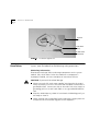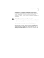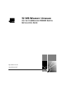
1
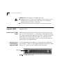
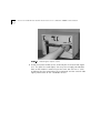
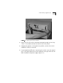
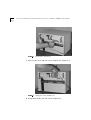
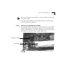
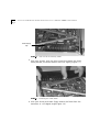
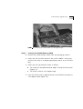
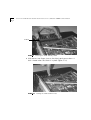
32 MB MEMORY UPGRADE
®
http://www.3com.com/
Part No. DIA37OU-1AAA02
Published November 1998
FOR THE COREBUILDER
INSTALLATION GUIDE
7000HD SWITCH
3Com Corporation
5400 Bayfront Plaza
Santa Clara, California
95052-8145
Copyright © 1998, 3Com Corporation. All rights reserved. No part of this documentation may be reproduced
in any form or by any means or used to make any derivative work (such as translation, transformation, or
adaptation) without written permission from 3Com Corporation.
3Com Corporation reserves the right to revise this documentation and to make changes in content from time
to time without obligation on the part of 3Com Corporation to provide notification of such revision or change.
3Com Corporation provides this documentation without warranty, term, or condition of any kind, either
implied or expressed, including, but not limited to, the implied warranties, terms or conditions of
merchantability, satisfactory quality, and fitness for a particular purpose. 3Com may make improvements or
changes in the product(s) and/or the program(s) described in this documentation at any time.
If there is any software on removable media described in this documentation, it is furnished under a license
agreement included with the product as a separate document, in the hard copy documentation, or on the
removable media in a directory file named LICENSE.TXT or !LICENSE.TXT. If you are unable to locate a copy,
please contact 3Com and a copy will be provided to you.
UNITED STATES GOVERNMENT LEGEND
If you are a United States government agency, then this documentation and the software described herein are
provided to you subject to the following:
All technical data and computer software are commercial in nature and developed solely at private expense.
Software is delivered as “Commercial Computer Software” as defined in DFARS 252.227-7014 (June 1995) or
as a “commercial item” as defined in FAR 2.101(a) and as such is provided with only such rights as are
provided in 3Com’s standard commercial license for the Software. Technical data is provided with limited rights
only as provided in DFAR 252.227-7015 (Nov 1995) or FAR 52.227-14 (June 1987), whichever is applicable.
You agree not to remove or deface any portion of any legend provided on any licensed program or
documentation contained in, or delivered to you in conjunction with, this User Guide.
Unless otherwise indicated, 3Com registered trademarks are registered in the United States and may or may
not be registered in other countries.
3Com, the 3Com logo, Net Age, NETBuilder II, SuperStack, Transcend, and TranscendWare are registered
trademarks of 3Com Corporation. ATMLink, CoreBuilder, are trademarks of 3Com Corporation. 3ComFacts is
a service mark of 3Com Corporation.
CompuServe is a registered trademark of CompuServe, Inc. Microsoft, MS-DOS, Windows, and Windows NT
are registered trademarks of Microsoft Corporation.
HP OpenView is a registered trademark of Hewlett-Packard Company. SunNet Manager is a trademark of the
Sun Microsystems, Inc.
All other company and product names may be trademarks of the respective companies with which they are
associated.
Document designed and written by Laura Novich, photography by Oren Ben-Ami. Production by 3Com.
ii
CONTENTS
ABOUT THIS GUIDE
Scope of This Guide i
Who Should Use This Guide
Organization i
Conventions ii
Related Documentation ii
1
i
INTRODUCTION
General 1-1
Installation Upgrade KIt 1-1
Safety Precautions 1-2
ESD Safety Information 1-2
Information sur la prévention de décharges électrostatiques 1-3
Sicherheitsinformationen für elektrostatische Entladungen 1-3
32MB Memory Upgrade SIMM 1-4
Inspecting the 32MB SIMM 1-4
Identifying the 32MB Memory Upgrade SIMM 1-4
2
32MB MEMORY UPGRADE INSTALLATION ON
COREBUILDER 7000HD SWITCH MODULE
THE
32Mb Memory Upgrade Steps 2-1
Step 1: Removing the CoreBuilder 7000HD Switch Module from the
Chassis 2-1
Step 2: Removing the 16MB Memory SIMM 2-5
Step 3: Inserting the 32MB Memory SIMM 2-7
Step 4: Returning the CoreBuilder 7000HD Switch Module back to the
Chassis 2-9
Verifying 32MB Memory Upgrade 2-9
INDEX
iv
ABOUT THIS GUIDE
Scope of This
Guide
Who Should Use
This Guide
Organization
The 32MB Memory Upgrade for the CoreBuilder 7000HD Switch
Installation Guide provides all the information needed to mount the
32MB Memory SIMM on the CoreBuilder 7000HD Switch Module.
This document provides a step-by-step installation procedure for the
32MB Memory SIMM.
The 32MB Memory Upgrade for the CoreBuilder 7000HD Switch
Installation Guide is intended for anyone moderately familiar and
handy with common household tools. No prior knowledge of
3Com’s CoreBuilder networking equipment is necessary to
understand this manual.
The 32MB Memory Upgrade for the CoreBuilder 7000HD Switch
Installation Guide is organized so that the information needed can
be accessed directly. The parts of the document are described
below.
Chapter 1: Introduction
This chapter presents the Memory Upgrade SIMM and assembly kit
(combined as 3C37041) at a glance, describes required materials
and explains the safety precautions that must be followed when
installing the 32MB SIMM.
Chapter 2: 32MB Installation on the CoreBuilder 7000HD Switch
Module
This chapter describes a photo-illustrated procedure of the various
stages required to mount the 32Mb Memory SIMM on the
CB7000HD Switch Module.
ii
ABOUT THIS GUIDE
Conventions
Table 1 lists the icons and typographical conventions used in this
guide.
Notice icons indicate statements that you need to read before
continuing in the guide. Table 1 describes these icons.
Notice Icons
Icon
Related
Documentation
Type
Description
Information
Note
Information notes call attention to important
features or instructions.
Caution
Cautions alert you to personal safety risk, system
damage, or loss of data.
Warning
Warnings alert you to the risk of severe personal
injury.
The complete documentation for the interface boards and the
CoreBuilder 7000HD which they serve includes:
CoreBuilder 7000HD Installation and Startup Guide
(#DUA3700-0BAA03)
CoreBuilder 7000HD User Guide (# DUA3700-0AAA05)
Table 2 describes important information in the CoreBuilder 7000HD
documentation to help you locate the information you need.
CoreBuilder 7000/7000HD Documentation Road Map
.
If you want to...
Read...
Get an overview of the CoreBuilder 7000 ATM Installation and Startup
switch, including system components.
Guide
Learn about various configurations in which
you can install your CoreBuilder 7000 ATM
switch.
Installation and Startup
Guide
Install and power up your CoreBuilder 7000
ATM switch.
Installation and Startup
Guide
Learn about how you administer and manage
the CoreBuilder 7000 ATM switch.
Installation and Startup
Guide / User Guide
Related Documentation
iii
CoreBuilder 7000/7000HD Documentation Road Map (continued)
If you want to...
Read...
Learn about ATM and how it is implemented
in the CoreBuilder 7000 ATM switch.
User Guide
Learn about LAN Emulation and how it is
implemented in the CoreBuilder 7000 ATM
switch.
User Guide
Find out what type of configuration tasks you
can perform on the CoreBuilder 7000 ATM
switch.
User Guide
Perform configuration or administration tasks
using the Administration Console.
Installation and Startup
Guide / User Guide
Get assistance.
Technical Support Appendix
in any guide
iv
ABOUT THIS GUIDE
1
INTRODUCTION
General
The CoreBuilder 7000HD Switch Engine 32MB Memory Upgrade Kit
(3C37041) increases the ATM switching capacity, measured in calls,
by a factor of four to five. This upgrade is available in conjunction
with the CoreBuilder 7000 family software version 4.0, and replaces
the existing 16MB memory included on the switch board.
Installation of the memory upgrade is simple, and no other
modifications are required. Software version 4.0 automatically
recognizes the larger memory, and immediately utilizes it for
additional call capacity. Included with this kit is an ESD wrist strap
to prevent damage to the SIMM and to the switch from electrostatic
emmisions.
Installation
Upgrade KIt
In order to help you, 3Com supplies all the tools necessary for the
upgrade in the installation upgrade kit. The installation upgrade kit
supplied with the 32MB SIMM contains the following items (see
Figure 1-1):
ESD wrist strap
A #1 flat head screwdriver
Release key - to be used to remove the switch board from the
chassis according to the instructions on the following pages
1-2
CHAPTER 1: INTRODUCTION
Special
Key
ESD Wrist
Strap
#1 Flat Head
Screwdriver
Safety
Precautions
Installation Upgrade Kit
Before working with any component in the CoreBuilder 7000
System, read and adhere to the following safety precautions.
ESD Safety Information
Electrostatic Discharge (ESD) can damage components on the system
module. ESD, which occurs when the module or a component is
improperly handled, can cause complete or intermittent failures.
CAUTION: To prevent ESD-related damage:
Always wear the ESD wrist strap supplied, ensuring that the strap is
firmly secured to your wrist. The other end should be connected to a
grounded surface Connect the clip on the end of the wrist strap to a
grounding point on an anti-static table or to a grounded distribution
rack.
Keep the 32MB Memory SIMM in its antistatic shielded bag until you
are ready to install it.
When working with CoreBuilder 7000 components, always place the
component on the antistatic bag that it was shipped in.
Safety Precautions
1-3
Information sur la prévention de décharges électrostatiques
Les décharges électrostatiques peuvent endommager des éléments du
module. Ces décharges, qui surviennent lors d’une manipulation
inadéquate du module, peuvent entraîner une défaillance temporaire ou
permanente.
ATTENTION: Pour éviter des dommages électrostatiques:
Assurez-vous d’être bien branché à la terre. Utilisez un sous-pied et un
tapis relié à la terre ou portez un bracelet mis à la terre et veillez à ce
que le contact dermique soit bon.
Conservez le module dans un sac antistatique jusqu’à son installation.
Sicherheitsinformationen für elektrostatische Entladungen
Elektrostatische Entladungen (ESD) können einzelne Baugruppen oder
das gesamte Modul beschädigen. ESD können vorkommen, wenn das
Modul nicht richtig gehandhabt wird und können eine dauerhafte oder
zeitweilige Fehlfunktion bewirken.
1-4
CHAPTER 1: INTRODUCTION
VORSICHT: Zur Verhütung von Schadën durch ESD:
Vergewissern Sie sich, daß Sie richtig geerdet sind. Benutzen Sie ein
Fußband und eine geerdete Matte oder tragen Sie ein geerdetes
Handgelenkband mit gutem Hautkontakt.
Lassen Sie das Modul bis zur Installation in der Anti-Statik-Tasche.
32MB Memory
Upgrade SIMM
This section explains how to handle and identify the 32MB Memory
Upgrade SIMM.
Inspecting the 32MB
SIMM
Before touching the memory SIMM make sure that you are using
the ESD wrist strap and that it is connected as described previously.
The SIMM should only be held from the sides. Carefully remove the
SIMM from the antistatic bag and inspect it for damages. If the
SIMM appears to be damaged, return it to the antistatic bag and
contact your 3Com Representitive.
Identifying the
32MB Memory
Upgrade SIMM
To accurately identify the product as 32MB check for a label with
the inscription “32MB” on the upper component side of the SIMM
(Figure 1-2). Make sure the SIMM has the 32MB label.
32MB label
32MB Memory SIMM
32MB MEMORY UPGRADE
INSTALLATION ON THE
COREBUILDER 7000HD SWITCH
MODULE
2
32MB Memory
Upgrade Steps
Step 1
Removing the CoreBuilder 7000HD Switch Module from the
Chassis
Before starting, make sure that you wearing the ESD wrist strap and
that you are properly connected to grounding equipment as
described in “Safety Precautions” on page 1-2.
Disconnect the cables from the module’s ports. Ensure that there is a
record of where the cables are attached so that you can correctly
re-connect them to the module when finished.
With the #1 flathead screwdriver supplied, loosen the two captive
screws located on the far left and right of the module near the
ejector handles (Figure 2-1). Do not remove the screws.
2-2
CHAPTER 2: 32MB MEMORY UPGRADE INSTALLATION ON THE COREBUILDER 7000HD SWITCH MODULE
Loosening the Captive Screws
Grasp the ejector handles of the card and push them outward (Figure
2-2). This ejects the card slightly. You may have to apply considerable
force to the handles in order to eject the card. You will hear a “click”
to indicate that the connections have separated, and the card will slide
slightly forward out of the CoreBuilder chassis.
32MB Memory Upgrade Steps
2-3
Opening the Ejector Handles
Make sure that the screws have been loosened enough so that they
“float” in the holes and do not catch on the front panel.
Keeping the ejectors in the openmost position, remove the switch
module by sliding it outwards.
If you experience difficulty in removing the switch, insert the special
key in the space above the switch module on the right side near the
black handle of the power supply (Figure 2-3).
2-4
CHAPTER 2: 32MB MEMORY UPGRADE INSTALLATION ON THE COREBUILDER 7000HD SWITCH MODULE
Inserting the Special Key
Raise the key and slide the switch module out (Figure 2-4).
Sliding the Switch Module Out
Using both hands, pull the switch module out.
32MB Memory Upgrade Steps
2-5
Only use the special key provided if you have difficulty in removing
the switch module.
Place the switch module on a grounded surface or antistatic bag
with all components facing up.
Step 2
Removing the 16MB Memory SIMM
The memory SIMM is located on the lower left corner of the module
when the front panel is facing you. (Figure 2-5) On the top of the
memory SIMM there are two metal spring clips (one on each side of
the SIMM) that hold the SIMM in place (Figure 2-6).
16MB Memory SIMM
Front Panel
Front View
Position of 16MB SIMM in CoreBuilder 7000HD Switch Module -
2-6
CHAPTER 2: 32MB MEMORY UPGRADE INSTALLATION ON THE COREBUILDER 7000HD SWITCH MODULE
Metal Spring
Clip
Side View of the Memory SIMM
With your thumbs, push the clips outward to release the SIMM.
When pressed, the SIMM releases and rises slightly (Figure 2-7).
Removing the 16MB SIMM
With your thumb and index finger, remove the SIMM from the
connector at a 45 degree angle (Figure 2-8).
32MB Memory Upgrade Steps
Step 3
2-7
Removing the 16MB SIMM at a 45 Degree Angle
Inserting the 32MB Memory SIMM
Remove the 32MB Memory SIMM from the packaging material.
Make sure that the front panel of the switch module is facing you,
and that the switch is on proper grounding material, or an antistatic
bag.
Make sure that you hold the SIMM as follows:
The cutout on the gold connector edge is facing the front panel
(Figure 1-2).
The SIMM is held at a 45 degree angle.
Insert the SIMM with its gold connector into the black connector at
a 45 degree angle (Figure 2-9).
2-8
CHAPTER 2: 32MB MEMORY UPGRADE INSTALLATION ON THE COREBUILDER 7000HD SWITCH MODULE
Cutout
Inserting the 32MB Memory SIMM
With one or two fingers (not on the chips) gently press down. A
click is heard when the SIMM is in place (Figure 2-10).
Pushing the 32MB SIMM in Place
Verifying 32MB Memory Upgrade
Step 4
2-9
Returning the CoreBuilder 7000HD Switch Module back to the
Chassis
Orient the Switch Module so its labelling is upright and make sure
the eject handles are in the outward position.
Insert the module into the chassis by placing it in the guides of the
selected slot and slide the module with two fingers until it stops. While
inserting the module, raise it up a little and slide it in.
Grab both ejector handles and push them inward. This locks the module
into the chassis. You may have to apply considerable pressure to the
handles. An audible “click” indicates that the connectors have engaged.
Verify that the card has been properly installed by observing its LEDs.
Tighten the module’s securing screws.
Verifying 32MB
Memory Upgrade
To verify that the switch module’s memory has been upgraded
successfully, follow the steps below:
Reconnect all the cables to the switch module's ports according to
the record you made of the cables.
Reconnect the power cable.
Login to the LMA with the username: .
From the LMA of the CoreBuilder 7000HD Switch Module, select
option and then select option
The following information should be displayed:
#
$
$
% %%&'%(%')
*+, -$ .$-
Check that the memory shown is 32M.
!"
2-10
CHAPTER 2: 32MB MEMORY UPGRADE INSTALLATION ON THE COREBUILDER 7000HD SWITCH MODULE
INDEX
Numbers
I
16MB memory SIMM
removing 2-5
32MB memory upgrade
verifying 2-9
32MB memory upgrade installation guide i
8-Port Board i
icons
notice ii
installation
memory upgrade 2-1
A
Administration Console iii
assembly kit i
ATM switch ii
C
conventions used in this guide ii
CoreBuilder 7000 Installation and Startup Guide ii
CoreBuilder 7000 Switch Module
removing 2-1
CoreBuilder 7000HD i, ii
User Guide ii
CoreBuilder 7000HD User Guide ii
D
documentation
related ii
K
key 2-3
L
LAN Emulation iii
LMA
Logging in 2-9
M
memory chipset i
memory SIMM
removing 2-5
memory upgrade
installing 2-1
verifying 2-9
memory upgrade installation guide i
N
notice icons ii
E
ejector handles 2-2
O
organization of this guide i
G
guide
conventions ii
organization i
scope i
R
related documentation ii
S
H
scope of this guide i
how to read documentation ii
T
typographical conventions ii
2
INDEX
V
verifying memory upgrade 2-9
W
who should use this guide i