1
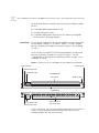
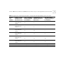
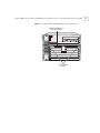
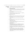
10-Port 100BASE-FX and
20-Port 10/100BASE-TX
Fast Ethernet Layer 2
Switching Modules
Quick Start Guide
For the CoreBuilder® 9000 Enterprise Switch
Module Descriptions
This guide describes key installation information for two
CoreBuilder® 9000 Fast Ethernet (FEN) Switching Modules:
■
The 10-port 100BASE-FX Fast Ethernet Layer 2 Switching Module
(Model Number 3CB9LF10MC) has ten 100 Mbps Ethernet fiber-optic
ports with SC connectors on its front panel and two 1-Gigabit ports
on the back for connection to the chassis backplane.
■
The 20-port 10/100BASE-TX Fast Ethernet Layer 2 Switching Module
(Model Number 3CB9LF20R) has twenty 10/100 Mbps RJ-45 ports on
its front panel and two 1-Gigabit ports on the back for connection to
the chassis backplane.
Each of these FEN Switching Modules operates as a Layer 2 switch and
occupies a single switching module slot in the CoreBuilder 9000 7-slot
chassis, 8-slot chassis, or 16-slot chassis.
Key Features
The 10/100BASE-TX and 100BASE-FX FEN Switching Modules support
the following key features:
■
Hot-swapping of modules
■
Management using the Administration Console
(a command line interface), the Web Management suite of
applications with an Internet browser, or SNMP-based applications
10-Port 100BASE-FX and 20-Port 10/100BASE-TX Fast Ethernet Layer 2 Switching Modules Quick Start Guide
For information about the software features that these modules support,
see the:
Front Panel
■
CoreBuilder 9000 Implementation Guide
■
Command Reference Guide
■
CoreBuilder 9000 Release Notes for the Fast Ethernet and Gigabit
Ethernet Layer 2 Switching Modules
On the 10-port 100BASE-FX FEN Switching Module, the front panel ports
are numbered 1 through 10, as shown in Figure 1. The two 1-Gigabit
ports on the back of the module (not shown in Figure 1) are numbered
11 and 12.
On the 20-port 10/100BASE-TX FEN Switching Module, the front panel
ports are numbered 1 through 20, as shown in Figure 1. The two
1-Gigabit ports on the back of the module (not shown in Figure 1) are
numbered 21 and 22.
Figure 1 Front Panels for the 10/100BASE-TX and 100BASE-FX FEN Modules
Ejector handle
Ejector handle
Module Status LED
Port Status LEDs
10/100BASE-TX
RJ-45 ports
3CB9LF20R
20
X
19
X
18
X
17
X
16
X
15
X
14
X
13
X
12
X
11
X
9X
10
X
8X
7X
6X
5X
4X
3X
2X
1
2
3
4
5
6
1X
OD
M
7
ST
AT
14
Model number
Module Status LED
10
9
8
7
6
5
4
3
2
1
1
2
3
4
5
Port Status LEDs
3CB9LF10MC
RX
TX
RX
TX
RX
TX
RX
TX
RX
TX
RX
TX
RX
TX
RX
TX
RX
TX
RX
TX
6
7
8
9
10
OD
ST
AT
100BASE-FX
M
2
Fiber-optic ports
(SC connectors)
In the 7-slot chassis, you install the modules horizontally with the LEDs at
the left. In the 8-slot chassis and the16-slot chassis, you install the
modules vertically with the LEDs at the top.
10-Port 100BASE-FX and 20-Port 10/100BASE-TX Fast Ethernet Layer 2 Switching Modules Quick Start Guide
Audience Description
3
This guide is intended for trained technical personnel only. Do not
attempt to install, remove, or replace the 10/100BASE-TX or 100BASE-FX
FEN Switching Modules if you have not had the proper training from
3Com. For training information in the United States and Canada, call
1-800-NET-3COM. For the numbers to call in other locations, visit the
3Com Web site:
www.3Com.com/support/
Safety Precautions
When you handle components in a CoreBuilder 9000 system, be sure
that you follow all safety precautions. To avoid electric shocks, burns, or
equipment damage, read and follow these warnings:
WARNING: Allow only trained service personnel to install, remove, or
replace any module in the chassis.
WARNING: Hazardous energy exists within the system. Use extreme
caution when you install, remove, or replace any module in the chassis.
When the system is on:
■
Never insert metal objects such as a screwdriver or a finger with
jewelry into open module slots.
■
Do not touch any connections within the chassis with your hands or
fingers.
WARNING: To ensure optical safety when installing a FEN Switching
Module, comply with the following precaution:
Although the data communication LEDs used in this product meet the
regulatory requirements for casual exposure to the eye, as with any
source of bright light, it is advised that you do not look into the light
source.
LED Safety Information: IEC 825 and EN60825, Class 1 LED Device. For
connection only to Class 1 LED Devices.
CLASS 1
LED PRODUCT
4
10-Port 100BASE-FX and 20-Port 10/100BASE-TX Fast Ethernet Layer 2 Switching Modules Quick Start Guide
ESD Safety Information
Electrostatic discharge (ESD) can damage components of the module.
ESD, which occurs when a module is improperly handled, can cause
complete or intermittent failures.
CAUTION: To prevent ESD-related damage:
Handling Precautions
■
Always wear an ESD wrist strap (not provided) when you handle a
module, ensuring that the strap makes good skin contact and is
properly grounded.
■
Keep the module in its antistatic bag until you are ready to install it.
When you handle a module, follow these precautions:
■
Always handle the module by the front panel only.
■
Do not touch the components, pins, leads, or solder connections.
■
Do not twist or otherwise force the module into the chassis when you
insert it into the module guides.
■
Before you push the module into the chassis, verify that the module
ejector handles are open.
■
When you slide the module into the 7-slot chassis, match the left and
right module guides. In the 8-slot chassis or 16-slot chassis, match the
upper and lower module guides.
For details, see “Installation Prerequisites” and “Installing the Module”
later in this guide.
10-Port 100BASE-FX and 20-Port 10/100BASE-TX Fast Ethernet Layer 2 Switching Modules Quick Start Guide
Unpacking
Instructions
5
Use the following procedure when you unpack a FEN Switching Module:
1 Verify that the module is the correct product by matching the 3C number
that is listed on the shipping box label to the 3C number that you ordered
(Model Number 3CB9LF10MC for the 10-port 100BASE-FX Fast Ethernet
Layer 2 Switching Module or Model Number 3CB9LF20R for the 20-port
10/100BASE-TX Fast Ethernet Layer 2 Switching Module).
2 Remove the module, in its antistatic bag, from the shipping box.
3 Observing the caution instructions, remove the module from its antistatic
bag and inspect it for physical damage.
CAUTION: Handle the module only by the front panel. Do not touch any
components, pins, leads, or solder connections.
If the module appears to be damaged, replace it in the antistatic bag, put
it back in the shipping box, and contact your network supplier.
4 Verify that the box also contains:
■
CoreBuilder 9000 Release Notes for the Fast Ethernet and Gigabit
Ethernet Layer 2 Switching Modules
■
10-Port 100BASE-FX and 20-Port 10/100BASE-TX Fast Ethernet
Layer 2 Switching Modules Quick Start Guide for the
CoreBuilder 9000 Enterprise Switch (this guide)
If the listed contents are not in your shipping box, contact your network
supplier.
All shipping boxes are reusable. After you remove the contents, replace
the packing materials in the box and store it for future use.
6
10-Port 100BASE-FX and 20-Port 10/100BASE-TX Fast Ethernet Layer 2 Switching Modules Quick Start Guide
Installation
Prerequisites
Before you install a module, make the following preparations:
■
Verify that the chassis is properly installed in a rack, on a table, or on a
shelf, according to the instructions in either of these guides:
■
■
7-Slot Chassis Quick Installation Guide for the CoreBuilder 9000
Enterprise Switch
Chassis Quick Installation Guide for the CoreBuilder 9000
Enterprise Switch 8-slot Chassis and 16-slot Chassis.
■
Have a flat-blade torque screwdriver available to secure the module to
the chassis after you install it.
■
Read the CoreBuilder 9000 Release Notes for the Fast Ethernet and
Gigabit Ethernet Layer 2 Switching Modules for important information
about installing and upgrading modules in an existing chassis or a new
chassis.
CAUTION: All modules in a CoreBuilder 9000 chassis must operate at
compatible software levels. You must verify the software release on all
new and existing modules in your chassis and upgrade as necessary. See
the CoreBuilder 9000 Release Notes for the Fast Ethernet and Gigabit
Ethernet Layer 2 Switching Modules for a module software compatibility
requirements table, mandatory upgrade procedures, and other important
information.
Module Placement
in the Chassis
Note the following chassis slot restrictions and recommendations when
you choose a chassis slot for the 10-port 100BASE-FX Fast Ethernet
Switching Module or the 20-port 10/100BASE-TX Fast Ethernet
Switching Module:
■
In the 7-slot chassis:
■
■
■
Do not install the module in slot 7. This slot is reserved for a
Gigabit Ethernet (GEN) Switch Fabric Module.
Install the module in slot 1, 2, 3, 4, 5, or 6.
In the 8-slot chassis:
■
■
Do not install the module in slot 7 or slot 8. These slots are
reserved for GEN Switch Fabric Modules.
Install the FEN Switching Module in slot 1, 2, 3, 4, 5, or 6.
10-Port 100BASE-FX and 20-Port 10/100BASE-TX Fast Ethernet Layer 2 Switching Modules Quick Start Guide
■
7
In the 16-slot chassis:
■
■
■
Do not install the module in slot 8 or slot 9. These slots are
reserved for GEN Switch Fabric Modules.
Install the module in slot 1, 2, 3, 4, 5, 6, 7, 10, 11, or 12.
3Com recommends that you do not install the module in slot 13,
14, 15, or 16 because these slots have only one connection to the
GEN Switch Fabric Module.
■
Table 1, Table 2, and Table 3 list the relationship between the
following:
■
24-port GEN Switch Fabric Module (SFM) (Model Number 3CB9FG24
or Model Number 3CB9FG24T)
■
10-port 100BASE-FX FEN Switching Module
■
Switching module slots in the 7-slot chassis, 8-slot chassis, and 16-slot
chassis, respectively
Table 4, Table 5, and Table 6 list the relationship between the following:
■
24-port GEN Switch Fabric Module (SFM)
■
20-port 10/100BASE-TX FEN Switching Module
■
Switching module slots in the 7-slot chassis, 8-slot chassis, and 16-slot
chassis, respectively
Table 7 and Table 8 list the relationship between the following:
■
9-port GEN Switch Fabric Module (SFM) (Model Number 3CB9FG9)
■
10-port 100BASE-FX FEN Switching Module
■
Switching module slots in the 7-slot chassis and 8-slot chassis,
respectively
Table 9 and Table 10 list the relationship between the following:
■
9-port GEN Switch Fabric Module (SFM)
■
20-port 10/100BASE-TX FEN Switching Module
■
Switching module slots in the 7-slot chassis and 8-slot chassis,
respectively
Use the table information to help select a slot for your module, as well as
administer the system after you have completed the installation.
8
10-Port 100BASE-FX and 20-Port 10/100BASE-TX Fast Ethernet Layer 2 Switching Modules Quick Start Guide
Table 1 Mapping the 24-port GEN SFM and the 10-port FEN Switching Module to the 7-slot Chassis
Chassis
Slot
Number
Number of SFM
Backplane Ports
Allocated to Slot
10-port Switching
Module Backplane
Port Numbers
SFM Backplane Port
Numbers Assigned to
Chassis Slot
SFM LED Numbers
Assigned to Backplane
Port Numbers
1
4; up to 2 can be
accessed by this
module
11
1
1
12
2
2
4; up to 2 can be
accessed by this
module
11
5
3
12
6
4
4; up to 2 can be
accessed by this
module
11
9
5
12
10
6
4; up to 2 can be
accessed by this
module
11
13
7
12
14
8
4; up to 2 can be
accessed by this
module
11
17
9
12
18
10
4; up to 2 can be
accessed by this
module
11
21
11
12
22
12
Not applicable
Not applicable
2
3
4
5
6
7
Reserved for an SFM Not applicable
10-Port 100BASE-FX and 20-Port 10/100BASE-TX Fast Ethernet Layer 2 Switching Modules Quick Start Guide
9
Table 2 Mapping the 24-port GEN SFM and the 10-port FEN Switching Module to the 8-slot Chassis
Chassis
Slot
Number
Number of SFM
Backplane Ports
Allocated to Slot
10-port Switching
Module Backplane
Port Numbers
SFM Backplane Port
Numbers Assigned to
Chassis Slot
SFM LED Numbers
Assigned to Backplane
Port Numbers
1
4; up to 2 can be
accessed by this
module
11
1
1
12
2
2
4; up to 2 can be
accessed by this
module
11
5
3
12
6
4
4; up to 2 can be
accessed by this
module
11
9
5
12
10
6
4; up to 2 can be
accessed by this
module
11
13
7
12
14
8
4; up to 2 can be
accessed by this
module
11
17
9
12
18
10
4; up to 2 can be
accessed by this
module
11
21
11
12
22
12
7
Reserved for an SFM
Not applicable
Not applicable
Not applicable
8
Reserved for an SFM
Not applicable
Not applicable
Not applicable
2
3
4
5
6
10
10-Port 100BASE-FX and 20-Port 10/100BASE-TX Fast Ethernet Layer 2 Switching Modules Quick Start Guide
Table 3 Mapping the 24-port GEN SFM and the 10-port FEN Switching Module to the 16-slot Chassis
Chassis
Slot
Number
Number of SFM
Backplane Ports
Allocated to Slot
10-port Switching
Module Backplane
Port Numbers
SFM Backplane Port
Numbers Assigned to
Chassis Slot
SFM LED Numbers
Assigned to Backplane
Port Numbers
1
2
11
1
1
12
2
2
11
3
3
12
4
4
11
5
5
12
6
6
11
7
7
12
8
8
11
9
9
12
10
10
11
11
11
12
12
12
11
13
13
12
14
14
2
3
4
5
6
7
2
2
2
2
2
2
8
Reserved for an SFM
Not applicable
Not applicable
Not applicable
9
Reserved for an SFM
Not applicable
Not applicable
Not applicable
10
2
11
15
15
12
16
16
11
17
17
12
18
18
11
19
19
12
20
20
11
12
2
2
13
1
11
21
21
14
1
11
22
22
15
1
11
23
23
16
1
11
24
24
10-Port 100BASE-FX and 20-Port 10/100BASE-TX Fast Ethernet Layer 2 Switching Modules Quick Start Guide
Table 4 Mapping the 24-port GEN SFM and the 20-port FEN Switching Module to the 7-slot Chassis
20-port Switching
Module
SFM Backplane Port
Backplane Port
Numbers Assigned to
Numbers
Chassis Slot
SFM LED Numbers
Assigned to Backplane
Port Numbers
4; up to 2 can be
accessed by this
module
21
1
1
22
2
2
4; up to 2 can be
accessed by this
module
21
5
3
22
6
4
4; up to 2 can be
accessed by this
module
21
9
5
22
10
6
4; up to 2 can be
accessed by this
module
21
13
7
22
14
8
4; up to 2 can be
accessed by this
module
21
17
9
22
18
10
4; up to 2 can be
accessed by this
module
21
21
11
22
22
12
Reserved for an SFM
Not applicable
Not applicable
Not applicable
Chassis
Slot
Number
Number of SFM
Backplane Ports
Allocated to Slot
1
2
3
4
5
6
7
11
12
10-Port 100BASE-FX and 20-Port 10/100BASE-TX Fast Ethernet Layer 2 Switching Modules Quick Start Guide
Table 5 Mapping the 24-port GEN SFM and the 20-port FEN Switching Module to the 8-slot Chassis
Chassis
Slot
Number
Number of SFM
Backplane Ports
Allocated to Slot
20-port Switching SFM Backplane Port
Module Backplane Numbers Assigned to
Port Numbers
Chassis Slot
SFM LED Numbers
Assigned to Backplane
Port Numbers
1
4; up to 2 can be
accessed by this
module
21
1
1
22
2
2
4; up to 2 can be
accessed by this
module
21
5
3
22
6
4
4; up to 2 can be
accessed by this
module
21
9
5
22
10
6
4; up to 2 can be
accessed by this
module
21
13
7
22
14
8
4; up to 2 can be
accessed by this
module
21
17
9
22
18
10
4; up to 2 can be
accessed by this
module
21
21
11
22
22
12
2
3
4
5
6
7
Reserved for an SFM Not applicable
Not applicable
Not applicable
8
Reserved for an SFM Not applicable
Not applicable
Not applicable
10-Port 100BASE-FX and 20-Port 10/100BASE-TX Fast Ethernet Layer 2 Switching Modules Quick Start Guide
Table 6 Mapping the 24-port GEN SFM and the 20-port FEN Switching Module to the 16-slot Chassis
Chassis
Slot
Number
Number of SFM
Backplane Ports
Allocated to Slot
20-port Switching SFM Backplane Port
Module Backplane Numbers Assigned to
Port Numbers
Chassis Slot
SFM LED Numbers
Assigned to Backplane
Port Numbers
1
2
21
1
1
22
2
2
21
3
3
22
4
4
21
5
5
22
6
6
21
7
7
22
8
8
21
9
9
22
10
10
21
11
11
22
12
12
21
13
13
22
14
14
2
3
4
5
6
7
2
2
2
2
2
2
8
Reserved for an SFM Not applicable
Not applicable
Not applicable
9
Reserved for an SFM Not applicable
Not applicable
Not applicable
10
2
21
15
15
22
16
16
21
17
17
22
18
18
21
19
19
22
20
20
11
12
2
2
13
1
21
21
21
14
1
21
22
22
15
1
21
23
23
16
1
21
24
24
13
14
10-Port 100BASE-FX and 20-Port 10/100BASE-TX Fast Ethernet Layer 2 Switching Modules Quick Start Guide
Table 7 Mapping the 9-port GEN SFM and the 10-port FEN Switching Module to the 7-slot Chassis
Chassis
Slot
Number
Number of SFM
Backplane Ports
Allocated to Slot
10-port Switching SFM Backplane Port
Module Backplane Numbers Assigned to
Port Numbers
Chassis Slot
SFM LED Numbers
Assigned to Backplane
Port Numbers
1
1
11
1
1
2
1
11
2
2
3
1
11
3
3
4
1
11
4
4
5
1
11
5
5
6
1
11
6
6
7
Reserved for an SFM
Not applicable
Not applicable
Not applicable
Table 8 Mapping the 9-port GEN SFM and the 10-port FEN Switching Module to the 8-slot Chassis
Chassis
Slot
Number
Number of SFM
Backplane Ports
Allocated to Slot
10-port Switching SFM Backplane Port
SFM LED Numbers
Module Backplane Numbers Assigned to Assigned to Backplane
Port Numbers
Chassis Slot
Port Numbers
1
1
11
1
1
2
1
11
2
2
3
1
11
3
3
4
1
11
4
4
5
1
11
5
5
6
1
11
6
6
7
Reserved for an SFM
Not applicable
Not applicable
Not applicable
8
Reserved for an SFM
Not applicable
Not applicable
Not applicable
10-Port 100BASE-FX and 20-Port 10/100BASE-TX Fast Ethernet Layer 2 Switching Modules Quick Start Guide
15
Table 9 Mapping the 9-port GEN SFM and the 20-port FEN Switching Module to in the 7-slot Chassis
Chassis
Slot
Number
Number of SFM
Backplane Ports
Allocated to Slot
20-port Switching
Module Backplane
Port Numbers
SFM Backplane Port
Numbers Assigned to
Chassis Slot
SFM LED Numbers
Assigned to Backplane
Port Numbers
1
1
21
1
1
2
1
21
2
2
3
1
21
3
3
4
1
21
4
4
5
1
21
5
5
6
1
21
6
6
7
Reserved for an SFM
Not applicable
Not applicable
Not applicable
Table 10 Mapping the 9-port GEN SFM and the 20-port FEN Switching Module to the 8-slot Chassis
Chassis
Slot
Number
Number of SFM
Backplane Ports
Allocated to Slot
20-port Switching
Module Backplane
Port Numbers
SFM Backplane Port
SFM LED Numbers
Numbers Assigned to Assigned to Backplane
Chassis Slot
Port Numbers
1
1
21
1
1
2
1
21
2
2
3
1
21
3
3
4
1
21
4
4
5
1
21
5
5
6
1
21
6
6
7
Reserved for an SFM
Not applicable
Not applicable
Not applicable
8
Reserved for an SFM
Not applicable
Not applicable
Not applicable
16
10-Port 100BASE-FX and 20-Port 10/100BASE-TX Fast Ethernet Layer 2 Switching Modules Quick Start Guide
Installing the Module
To install a FEN Switching Module:
1 Before you start the installation process, read and follow the instructions
in “Safety Precautions,” “Handling Precautions,” and “Installation
Prerequisites” earlier in this guide.
2 Select a chassis slot for your module, following the restrictions and
recommendations in “Module Placement in the Chassis” earlier in this
guide.
3 To expose a slot for the module, remove the blank faceplate.
Save this faceplate in case you need it in the future. Empty slots must be
covered to ensure proper airflow and cooling in the chassis.
3Com recommends that you remove the faceplate only for the slot where
you intend to install an individual module; leave the remaining faceplates
in the chassis.
4 Open the module ejector handles.
5 Begin to insert the module:
■
In the 7-slot chassis, hold the module horizontally with the LEDs to the
left and begin to insert the module using the guides on the left and
the right of the slot. Figure 2 shows the module position in a 7-slot
chassis.
■
In the 8-slot chassis and 16-slot chassis, hold the module vertically
with the LEDs at the top and begin to insert the module using the
guides on the top and the bottom of the slot. Figure 3 shows the
module position in a 16-slot chassis. The module position is the same
in an 8-slot chassis.
CAUTION: Do not twist or bend the module when you insert it.
6 Slide the module into the chassis by pushing firmly on the two ends of
the front panel near the ejector handles.
WARNING: Hazardous energy exists inside the chassis. Do not place
hands or objects into the chassis or touch any components on an inserted
module.
10-Port 100BASE-FX and 20-Port 10/100BASE-TX Fast Ethernet Layer 2 Switching Modules Quick Start Guide
Figure 2 Installing a FEN Switching Module into a 7-Slot Chassis
20-port Fast Ethernet
Switching Module
®
CoreBuilder 9000
R
9
22
24
3
2
1
Spring-loaded
screws
20
X
19
X
18
X
16
X
17
X
15
X
14
X
12
X
4
13
X
11
X
10
X
8X
9X
7X
6X
5X
4X
3X
2X
1X
5
3CB9LF20R
18
20
23
14
21
16
17
19
13
15
10
8
12
4
6
SE
2
9
7
ST
AT
11
1
ST
AT
7
1
2
3
4
5
6
M
OD
6
14
PR
I
M
OD
3
7
5
C
3CB9FG24
8
17
18
10-Port 100BASE-FX and 20-Port 10/100BASE-TX Fast Ethernet Layer 2 Switching Modules Quick Start Guide
Figure 3 Installing a FEN Switching Module into a 16-Slot Chassis
Spring-loaded
screw
®
CoreBuilder 9000
R
1
2
3
4
5
6
7
MO
D
7
8
MO
D
ST
AT
14
1
2
3
4
5
6
1X
2X
PR
I
1
9
SE
C
2
3
4
5
6
7
8
9
10
10
MO
D
ST
AT
PR
I
1
ST
AT
SE
C
2
3
4
5
6
7
8
9
10
11
12
11
12
13
14
13
14
15
16
15
16
17
18
17
18
19
20
19
20
21
22
21
22
23
24
23
24
3X
4X
5X
6X
7X
8X
9X
10
X
11
12
20-port
Fast Ethernet
Switching
Module
X
X
13
14
16
X
X
17
18
19
20
X
X
15
X
X
X
X
3CB9FG24
3CB9LF20R
Spring-loaded
screw
3CB9FG24
11
12
13
14
15
16
10-Port 100BASE-FX and 20-Port 10/100BASE-TX Fast Ethernet Layer 2 Switching Modules Quick Start Guide
19
7 To engage the module with the backplane, use both hands to perform
the following steps:
a Push firmly at the two ends of the front panel near the ejector handles
until you feel the module connectors make firm contact with the
backplane connectors.
b Put your left thumb on the left or top ejector handle and your right
thumb on the right or bottom ejector handle. Simultaneously, push
the ejector handles in towards the front panel until each handle is
parallel with the front panel.
You feel a slight resistance as the connectors fully engage.
CAUTION: If there is too much resistance when you try to close the
ejector handles, the module backplane connector may not be aligned.
Forcing the module into place can damage the module connectors and
backplane connectors. If necessary, remove and reinsert the module,
ensuring that the connectors are properly aligned. Do not tighten the
spring-loaded screws to seat the module.
8 To secure the module in the chassis, tighten the spring-loaded screws to a
torque specification of 3 to 5 inch-pounds.
CAUTION: Verify that the module screws are properly aligned with the
threaded holes in the chassis. If the screws are not aligned when you
tighten them, you may strip the threads and make it impossible to secure
the module.
To ensure that you tighten screws to torque specification, use a torque
screwdriver.
WARNING: To ensure adequate cooling airflow and continued product
safety agency compliance, install blank faceplates over all empty slots.
If the chassis is powered on, the module initialization process begins.
20
10-Port 100BASE-FX and 20-Port 10/100BASE-TX Fast Ethernet Layer 2 Switching Modules Quick Start Guide
Verifying Module
Operation
The 10-port 100BASE-FX FEN Switching Module has 10 Port Status LEDs
and the 20-port 10/100BASE-TX FEN Switching Module has 20 Port
Status LEDs. Each module has one Module Status LED.
Watch the LEDs during the system power-on diagnostics test to verify
proper module operation:
■
On the Module Status LED, the normal power-on test sequence is
Green – Yellow – Green – Flashing Green (while running the
diagnostic test) – Green
If the Module Status LED is Yellow after the diagnostics run, the module
has failed.
■
The Port Status LEDs are tested during the diagnostic test. The normal
test sequence is Yellow – Green – Off
Table 11 describes LED colors and definitions.
Table 11 Module and Port Status LED Indicators
LED
State or Color Definition
Module Status
Green
Power is on (normal operation).
Flashing Green
Diagnostics or software download is in
progress.
Yellow
Diagnostic failure.
Off
After initial insertion or module reset, the
LED remains unlit for approximately 3
seconds. Otherwise, an unlit LED
indicates that the module is not receiving
power.
Green
Port is enabled and link is up.
Flashing Green
Port is receiving or transmitting packets.
Yellow
Module or port is malfunctioning.
Off
Port is disabled or link is down.
Port Status
10-Port 100BASE-FX and 20-Port 10/100BASE-TX Fast Ethernet Layer 2 Switching Modules Quick Start Guide
Managing the
Module
21
You configure and manage a FEN Switching Module using several
interfaces. The following sections describe two of the interfaces.
Administration Console
The Administration Console is the embedded menu-driven command line
interface that you access from a terminal or through terminal emulation
software.
To manage the module from the Administration Console:
1 Log in to the EME.
For information about how to log in to the EME, see the CoreBuilder
9000 Enterprise Management Engine User Guide.
2 At the EME prompt, enter:
connect <slot>.1
where <slot> is the chassis slot number of the module that you want to
manage, and the number after the decimal point is a subslot number,
which is always 1.
The top level of the Administration Console menu for the module
appears.
3 Enter command strings to manage the module. For example, to display a
module baseline, enter:
module baseline display
For information about the Administration Console module commands,
see the Command Reference Guide.
Web Management
Web Management applications are an embedded part of the system.
They include WebConsole, DeviceView, and Performance monitoring
tools. Additional installable applications include online Help.
After you have set up the IP address for your system, you can access the
Web Management applications directly in your Web browser by entering
the IP address.
For information about setting up your IP address, see the Enterprise
Management Engine Quick Start Guide for the CoreBuilder 9000
Enterprise Switch. For additional information about Web Management,
see the Web Management User Guide for the CoreBuilder 9000
Enterprise Switch.
22
10-Port 100BASE-FX and 20-Port 10/100BASE-TX Fast Ethernet Layer 2 Switching Modules Quick Start Guide
Module
Specifications
The following tables list specifications for the 10-port 100BASE-FX and
20-port 10/100BASE-TX Fast Ethernet Layer 2 Switching Modules:
Cabling Requirements
Module
Required Cable Type
Maximum Segment Length
100BASE-FX
(3CB9LF10MC)
Multimode fiber
62.5/125 micron
Half-duplex mode: 400 m (1312 ft
Full-duplex mode: 2 km (1.2 mi)
10/100BASE-TX
(3CB9LF20R)
UTP Category 5
Up to 100 m (328 ft)
Environmental Requirements
Operating temperature
0 to 50 °C (32 to 122 °F)
Operating humidity
10% to 90% relative humidity, noncondensing
Storage temperature
–40 to 66 °C (–40 to 151 °F)
Storage humidity
5% to 95% relative humidity, noncondensing
Physical Specifications
Module
Dimensions
Weight
100BASE-FX
(3CB9LF10MC)
25.4 mm x 340.36 mm x 388.112 mm
(1 in. x 13.4 in. x 15.28 in.)
1.135 kg
(2.5 lb)
10/100BASE-TX
(3CB9LF20R)
25.4 mm x 340.36 mm x 388.112 mm
(1 in. x 13.4 in. x 15.28 in.)
1.1804 kg
(2.6 lb)
Power Specifications
Module
Voltage
Wattage
100BASE-FX
(3CB9LF10MC)
+5.2 V
25 W
+3.5 V
33 W
+12 V
2W
Total Wattage = 60
10/100BASE-TX
(3CB9LF20R)
+5.2 V
28 W
+3.5 V
41 W
+12 V
2W
Total Wattage = 71
10-Port 100BASE-FX and 20-Port 10/100BASE-TX Fast Ethernet Layer 2 Switching Modules Quick Start Guide
23
Regulatory Compliance
Safety
Related
CoreBuilder 9000
Documents
Emissions
■
CSA 22.2 No. 950
■
FCC Part 15 Class A
■
EN 60950
■
ICES003 Class A
■
IEC 60950 (formerly IEC 950)
■
VCCI Class A
■
UL 1950
■
EN 55022 Class A
■
EN 60825 -1, -2
■
EN 50082-1
■
CE Mark
■
AS3548 (C-Tick Mark)
■
CISPR 22 Class A
■
CE Mark
For detailed information about using and managing the FEN Switching
Modules, see the following documents:
■
CoreBuilder 9000 Implementation Guide
■
Command Reference Guide
■
CoreBuilder 9000 Enterprise Management Engine User Guide
■
Web Management User Guide for the CoreBuilder 9000 Enterprise
Switch
For the software code installation procedure as well as known problem
information for this module, see the CoreBuilder 9000 Release Notes for
the Fast Ethernet and Gigabit Ethernet Layer 2 Switching Modules.
For information about installing and powering on the system, see the
following documents:
■
CoreBuilder 9000 Enterprise Switch Getting Started Guide
■
7-Slot Chassis Quick Installation Guide for the CoreBuilder 9000
Enterprise Switch
■
Chassis Quick Installation Guide for the CoreBuilder 9000 Enterprise
Switch 8-slot Chassis and 16-slot Chassis
■
7-Slot Chassis Power Supply Installation Guide for the
CoreBuilder 9000 Enterprise Switch
■
Power Supply Installation Guide for the CoreBuilder 9000 Enterprise
Switch 8-slot Chassis and 16-slot Chassis
24
10-Port 100BASE-FX and 20-Port 10/100BASE-TX Fast Ethernet Layer 2 Switching Modules Quick Start Guide
You can view and print these and other current CoreBuilder 9000
documents from the following sources:
■
3Com Web site
http://support.3com.com/nav/switches.htm
■
CoreBuilder 9000 Documentation CD-ROM
This CD-ROM is included in the chassis shipping box. You can also
order the CD-ROM separately (Order Number 3CB9DB).
3Com Corporation LIMITED WARRANTY
10-Port 100BASE-FX Fast Ethernet Layer 2 Switching Module (Model Number 3CB9LF10MC) and 20-Port 10/100BASE-TX
Fast Ethernet Layer 2 Switching Module (Model Number 3CB9LF20R) for the CoreBuilder® 9000 Enterprise Switch
HARDWARE
3Com warrants to the end user (“Customer”) that this hardware product will be free from defects in workmanship
and materials, under normal use and service, for one (1) year from the date of purchase from 3Com or its authorized
reseller.
3Com’s sole obligation under this express warranty shall be, at 3Com’s option and expense, to repair the defective
product or part, deliver to Customer an equivalent product or part to replace the defective item, or if neither of the
two foregoing options is reasonably available, 3Com may, in its sole discretion, refund to Customer the purchase
price paid for the defective product. All products that are replaced will become the property of 3Com. Replacement
products may be new or reconditioned. 3Com warrants any replaced or repaired product or part for ninety (90) days
from shipment, or the remainder of the initial warranty period, whichever is longer.
SOFTWARE
3Com warrants to Customer that each software program licensed from it will perform in substantial conformance to
its program specifications, for a period of ninety (90) days from the date of purchase from 3Com or its authorized
reseller. 3Com warrants the media containing software against failure during the warranty period. No updates are
provided. 3Com’s sole obligation under this express warranty shall be, at 3Com’s option and expense, to refund the
purchase price paid by Customer for any defective software product, or to replace any defective media with software
which substantially conforms to applicable 3Com published specifications. Customer assumes responsibility for the
selection of the appropriate applications program and associated reference materials. 3Com makes no warranty or
representation that its software products will meet Customer’s requirements or work in combination with any
hardware or applications software products provided by third parties, that the operation of the software products
will be uninterrupted or error free, or that all defects in the software products will be corrected. For any third-party
products listed in the 3Com software product documentation or specifications as being compatible, 3Com will make
reasonable efforts to provide compatibility, except where the noncompatibility is caused by a “bug” or defect in the
third party’s product or from use of the software product not in accordance with 3Com’s published specifications or
user manual.
THIS 3COM PRODUCT MAY INCLUDE OR BE BUNDLED WITH THIRD-PARTY SOFTWARE, THE USE OF WHICH IS
GOVERNED BY A SEPARATE END-USER LICENSE AGREEMENT. THIS 3COM WARRANTY DOES NOT APPLY TO SUCH
THIRD-PARTY SOFTWARE. FOR THE APPLICABLE WARRANTY, PLEASE REFER TO THE END-USER LICENSE
AGREEMENT GOVERNING THE USE OF SUCH SOFTWARE.
YEAR 2000 WARRANTY
In addition to the Hardware Warranty and Software Warranty stated above, 3Com warrants that each product sold
or licensed to Customer on and after January 1, 1998, that is date sensitive will continue performing properly with
regard to such date data on and after January 1, 2000, provided that all other products used by Customer in
connection or combination with the 3Com product, including hardware, software, and firmware, accurately
exchange date data with the 3Com product, with the exception of those products identified at 3Com’s Web site,
http://www.3com.com/products/yr2000.html, as not meeting this standard. If it appears that any product that is
stated to meet this standard does not perform properly with regard to such date data on and after January 1, 2000,
and Customer notifies 3Com before the later of April 1, 2000, or ninety (90) days after purchase of the product from
3Com or its authorized reseller, 3Com shall, at its option and expense, provide a software update which would effect
the proper performance of such product, repair such product, deliver to Customer an equivalent product to replace
such product, or, if none of the foregoing is feasible, refund to Customer the purchase price paid for such product.
Any software update or replaced or repaired product will carry a Year 2000 Warranty for ninety (90) days after
purchase or until April 1, 2000, whichever is later.
OBTAINING WARRANTY
SERVICE
Customer must contact a 3Com Corporate Service Center or an Authorized 3Com Service Center within the
applicable warranty period to obtain warranty service authorization. Dated proof of purchase from 3Com or its
authorized reseller may be required. Products returned to 3Com’s Corporate Service Center must be preauthorized
by 3Com with a Return Material Authorization (RMA) number or User Service Order (USO) number marked on the
outside of the package, and sent prepaid and packaged appropriately for safe shipment, and it is recommended that
they be insured or sent by a method that provides for tracking of the package. Responsibility for loss or damage does
not transfer to 3Com until the returned item is received by 3Com. The repaired or replaced item will be shipped to
Customer, at 3Com’s expense, not later than thirty (30) days after 3Com receives the defective product.
3Com shall not be responsible for any software, firmware, information, or memory data of Customer contained in,
stored on, or integrated with any products returned to 3Com for repair, whether under warranty or not.
Dead- or Defective-on-Arrival. In the event a product completely fails to function or exhibits a defect in materials or
workmanship within the first forty-eight (48) hours of installation but no later than thirty (30) days after the date of
purchase, and this is verified by 3Com, it will be considered dead- or defective-on-arrival (DOA) and a replacement
shall be provided by advance replacement. The replacement product will normally be shipped not later than three (3)
business days after 3Com’s verification of the DOA product, but may be delayed due to export or import procedures.
The shipment of advance replacement products is subject to local legal requirements and may not be available in all
locations. When an advance replacement is provided and Customer fails to return the original product to 3Com
within fifteen (15) days after shipment of the replacement, 3Com will charge Customer for the replacement product,
at list price.
Advance Replacement is provided for ninety (90) days, after which time it may be available for a specified fee. 3Com
will make commercially reasonable efforts to ship the replacement product not later than five (5) business days after
receiving the request for advance replacement, but may be delayed due to product availability or export or import
procedures. The shipment of advance replacement products is subject to local legal requirements and may not be
available in all locations. When an advance replacement is provided and Customer fails to return the original product
to 3Com within fifteen (15) days after shipment of the replacement, 3Com will charge Customer for the
replacement, at list price. This advance replacement is different from the fee-based Advance Hardware Replacement
Service, which is available as a contracted service offering.
INCLUDED SERVICES:
Telephone Support, with coverage for basic troubleshooting only, will be provided for ninety (90) days from the date
of purchase, on a commercially reasonable efforts basis. Please refer to the Technical Support appendix in the Getting
Started Guide for telephone numbers.
3Com’s Web and Bulletin Board Services provide 3Knowledgebase, bug tracking, documentation, release notes, and
some software maintenance releases at no charge.
WARRANTIES EXCLUSIVE
IF A 3COM PRODUCT DOES NOT OPERATE AS WARRANTED ABOVE, CUSTOMER’S SOLE REMEDY FOR BREACH OF
THAT WARRANTY SHALL BE REPAIR, REPLACEMENT, OR REFUND OF THE PURCHASE PRICE PAID, AT 3COM’S
OPTION. TO THE FULL EXTENT ALLOWED BY LAW, THE FOREGOING WARRANTIES AND REMEDIES ARE EXCLUSIVE
AND ARE IN LIEU OF ALL OTHER WARRANTIES, TERMS, OR CONDITIONS, EXPRESS OR IMPLIED, EITHER IN FACT OR
BY OPERATION OF LAW, STATUTORY OR OTHERWISE, INCLUDING WARRANTIES, TERMS, OR CONDITIONS OF
MERCHANTABILITY, FITNESS FOR A PARTICULAR PURPOSE, SATISFACTORY QUALITY, CORRESPONDENCE WITH
DESCRIPTION, AND NONINFRINGEMENT, ALL OF WHICH ARE EXPRESSLY DISCLAIMED. 3COM NEITHER ASSUMES
NOR AUTHORIZES ANY OTHER PERSON TO ASSUME FOR IT ANY OTHER LIABILITY IN CONNECTION WITH THE SALE,
INSTALLATION, MAINTENANCE, OR USE OF ITS PRODUCTS.
3COM SHALL NOT BE LIABLE UNDER THIS WARRANTY IF ITS TESTING AND EXAMINATION DISCLOSE THAT THE
ALLEGED DEFECT OR MALFUNCTION IN THE PRODUCT DOES NOT EXIST OR WAS CAUSED BY CUSTOMER’S OR
ANY THIRD PERSON’S MISUSE, NEGLECT, IMPROPER INSTALLATION OR TESTING, UNAUTHORIZED ATTEMPTS TO
OPEN, REPAIR, OR MODIFY THE PRODUCT, OR ANY OTHER CAUSE BEYOND THE RANGE OF THE INTENDED USE, OR
BY ACCIDENT, FIRE, LIGHTNING, POWER CUTS OR OUTAGES, OTHER HAZARDS, OR ACTS OF GOD.
LIMITATION OF LIABILITY
TO THE FULL EXTENT ALLOWED BY LAW, 3COM ALSO EXCLUDES FOR ITSELF AND ITS SUPPLIERS ANY LIABILITY,
WHETHER BASED IN CONTRACT OR TORT (INCLUDING NEGLIGENCE), FOR INCIDENTAL, CONSEQUENTIAL,
INDIRECT, SPECIAL, OR PUNITIVE DAMAGES OF ANY KIND, OR FOR LOSS OF REVENUE OR PROFITS, LOSS OF
BUSINESS, LOSS OF INFORMATION OR DATA, OR OTHER FINANCIAL LOSS ARISING OUT OF OR IN CONNECTION
WITH THE SALE, INSTALLATION, MAINTENANCE, USE, PERFORMANCE, FAILURE, OR INTERRUPTION OF ITS
PRODUCTS, EVEN IF 3COM OR ITS AUTHORIZED RESELLER HAS BEEN ADVISED OF THE POSSIBILITY OF SUCH
DAMAGES, AND LIMITS ITS LIABILITY TO REPAIR, REPLACEMENT, OR REFUND OF THE PURCHASE PRICE PAID, AT
3COM’S OPTION. THIS DISCLAIMER OF LIABILITY FOR DAMAGES WILL NOT BE AFFECTED IF ANY REMEDY
PROVIDED HEREIN SHALL FAIL OF ITS ESSENTIAL PURPOSE.
DISCLAIMER
Some countries, states, or provinces do not allow the exclusion or limitation of implied warranties or the limitation of
incidental or consequential damages for certain products supplied to consumers, or the limitation of liability for
personal injury, so the above limitations and exclusions may be limited in their application to you. When the implied
warranties are not allowed to be excluded in their entirety, they will be limited to the duration of the applicable
written warranty. This warranty gives you specific legal rights which may vary depending on local law.
GOVERNING LAW
This Limited Warranty shall be governed by the laws of the State of California, U.S.A., excluding its conflicts of laws
principles and excluding the United Nations Convention on Contracts for the International Sale of Goods.
3Com Corporation, 5400 Bayfront Plaza, P.O. Box 58145, Santa Clara, CA 95052-8145 (408) 326-5000
EMISSIONS COMPLIANCE
STATEMENTS FOR CLASS A
PRODUCTS
Federal Communications
Commission Notice
This equipment has been tested and found to comply with the limits for a Class A digital device, pursuant to part 15
of the FCC rules. These limits are designed to provide reasonable protection against harmful interference when the
equipment is operated in a commercial environment. This equipment generates, uses, and can radiate radio
frequency energy and, if not installed and used in accordance with the instruction manual, may cause harmful
interference to radio communications. Operation of this equipment in a residential area is likely to cause harmful
interference, in which case the user will be required to correct the interference at his or her own expense.
Canadian Emissions
Requirements
This Class A digital apparatus meets all requirements of the Canadian Interference-Causing Equipment Regulations.
Cet appareil numérique de la classe A respecte toutes les exigences du Règlement sur le matériel brouilleur du
Canada.
VCCI Class A Compliance
This is a Class A product based on the standard of the Voluntary Control Council for Interference by Information
Technology Equipment (VCCI). If this equipment is used in a domestic environment, radio disturbance may arise.
When such trouble occurs, the user may be required to take corrective actions.
EMC DIRECTIVE
STATEMENT
EMC Directive Compliance
This equipment was tested and found to conform to the Council Directive 89/336/EEC for electromagnetic
compatibility. Conformity with this Directive is based upon compliance with the following harmonized standards:
EN 55022
Limits and Methods of Measurement of Radio Interference
EN 50082-1
Electromagnetic Compatibility Generic Immunity Standard:
Residential, Commercial, and Light Industry
Warning: This is a Class A product. In a domestic environment, this product may cause radio interference, in which
case you may be required to take adequate measures.
LOW VOLTAGE DIRECTIVE
STATEMENT
Low Voltage Directive
Compliance
This equipment was tested and found to conform to the Council Directive 72/23/EEC for safety of electrical
equipment. Conformity with this Directive is based upon compliance with the following harmonized standard:
EN 60950
Safety of Information Technology Equipment
GENERAL APPROVAL
STATEMENT FOR UK
UK General Approval Statement
This equipment is manufactured to the international Safety Standard EN60950 and is approved in the UK under the
General Approval Number NS/G/12345/J/100003 for indirect connection to the public telecommunication network.
AUSTRALIAN EMC
FRAMEWORKS STATEMENT
Australian EMC Frameworks
Compliance
This product conforms to the EMC Frameworks and meets the Class A limits of AS3548.
3Com Corporation
5400 Bayfront Plaza
Santa Clara, California
95052-8145
Copyright © 1999, 3Com Corporation. All rights reserved. No part of this documentation may be reproduced in
any form or by any means or used to make any derivative work (such as translation, transformation, or
adaptation) without written permission from 3Com Corporation. 3Com Corporation reserves the right to revise
this documentation and to make changes in content from time to time without obligation on the part of
3Com Corporation to provide notification of such revision or change.
3Com Corporation provides this documentation without warranty, term, or condition of any kind, either implied
or expressed, including, but not limited to, the implied warranties, terms, or conditions of merchantability,
satisfactory quality, and fitness for a particular purpose. 3Com may make improvements or changes in the
product(s) and/or the program(s) described in this documentation at any time.
3Com registered trademarks are registered in the United States and may or may not be registered in other
countries. 3Com, the 3Com logo, and CoreBuilder are registered trademarks of 3Com Corporation.
All other company and product names may be trademarks of the respective companies with which they are
associated.
http://www.3com.com/
Part No. 10013072
Published August 1999