1
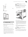
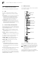
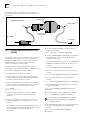
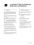
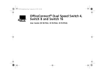
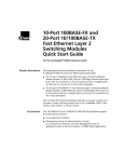
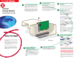
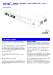
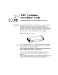
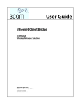
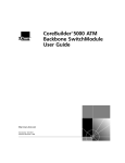
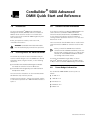
®
1.0
CoreBuilder® 5000 Advanced
DMM Quick Start and Reference
Introduction
The 3Com CoreBuilder® 5000 Advanced Distributed
Management Module (A/DMM) combines all advanced
DMM and hub controller functions on a module that
installs in the 3Com CoreBuilder 5000 Integrated System
Hub controller bay.
Before you unpack the module, read Section 5.0,
"Installation Precautions".
WARNING: CoreBuilder 5000 hubs and modules
must be installed only by trained service personnel.
2.0
3.0
If you plan to install the CoreBuilder 5000 A/DMM in the
same hub with a CoreBuilder 5000 Fault-Tolerant
Controller Module (Model Number 3C96000M-RCTL),
ensure that the Fault-Tolerant Controller Module is
running software Operational Version v1.15 or later and
Boot Version v1.04.
3Com recommends that all DMMs that are installed in the
same hub with the A/DMM run software Version v6.0 or
later.
Before you install the A/DMM into a hub that
contains an RCTL and DMM or DMM-EC, make sure
that the RCTL is running Version v1.15 code or later
and that the installed DMM or DMM-EC modules
are running Version v6.00 or later.
Learning About the Advanced DMM
This document provides the basic information that you
need to install and begin to use the A/DMM. For detailed
information about using this module, see the following
documents:
■
CoreBuilder 5000 Distributed Management Module
User Guide for software Version v6.00 or later
■
CoreBuilder 5000 Integrated System Hub Installation
and Operation Guide
You can view these documents on the 3Com DocsOnCD
CD-ROM that ships with this product.
To order paper documents, contact your network supplier,
or call 3Com Corporation at 1-800-724-2447 and choose
option 3.
Software Version Information
To manage the A/DMM through SNMP, use 3Com
Transcend ® Network Control Services for UNIX, Version
v5.00, or 3Com CoreBuilder 5000 Manager for Windows.
4.0
Power Budget Information
The CoreBuilder 5000 A/DMM consumes power as
follows:
■
12 W @ +5 V
■
1.0 W @ +12 V
■
0.25 W @ –5 V
■
0.50 W @ –12 V
■
0 W @ +2 V
Part Number 10012820
2
5.0
CORE BUILDER® 5000 ADVANCED DMM QUICK S TART
Installation Precautions
Electrostatic discharge (ESD) can damage static-sensitive
devices on circuit boards. Follow these precautions:
■
Do not remove the module from its antistatic bag until
you are ready to inspect or install it.
■
Handle the module by the front panel only.
■
Use proper grounding techniques when you install the
module. These techniques include using a foot strap
and grounded mat, wearing a grounded static
discharge wrist strap, or touching the grounded rack or
other grounded source just before you handle the
module.
AND
R EFERENCE
5 Ensure that the CoreBuilder 5000 A/DMM Kit contains
the following items:
■
CoreBuilder 5000 A/DMM
(Model Number 3C96000M-CMGT)
■
CoreBuilder 5000 A/DMM Adapter Cable
To order an additional A/DMM Adapter Cable, call
Allied Electronics nationwide number,
1-(800)-433-5700 and order
Part Number CA111972-35.
■
4 MB DRAM Memory Expansion Card
■
Release Note for CoreBuilder 5000 Management
Products
■
3Com DocsOnCD CD-ROM
When you handle CoreBuilder 5000 modules, follow these
precautions to avoid component damage:
■
CoreBuilder 5000 DMM Command Quick Reference
Guide
■
Do not twist or otherwise force CoreBuilder 5000
modules into the hub when you insert modules into the
module guides.
■
CoreBuilder 5000 Advanced DMM Quick Start and
Reference (this document)
■
■
Match the upper and lower module guides while you
slide the module into place.
CoreBuilder 5000 Integrated System Hub Reference
Library
■
Do not push the module all the way into the hub until
the module ejectors (if any) are open.
7.0
Installing Expansion Memory
To install expansion memory on the A/DMM:
6.0
Unpacking Procedure
Follow this procedure to unpack your module:
1 Verify that the module is the model that you ordered by
examining the model number on the side of the
shipping carton.
2 Remove the module, in its antistatic bag, from the
shipping carton.
3 Following the instructions in Section 5.0, "Installation
Precautions", remove the module from the antistatic
bag and inspect it for damage.
If the module appears to be damaged, return it to the
antistatic bag, repack it in the shipping carton, and
contact your local supplier.
Keep the shipping carton and antistatic bag in which
your module was shipped so that you can repackage
the module for storage or shipment.
4 Record the serial number of your module. Use the
HubPlanning Charts, which are located in the
CoreBuilder 5000 Integrated System Hub Reference
Library that is shipped with the CoreBuilder 5000
A/DMM Kit.
1 Locate the Expansion Memory Card holder on the
A/DMM.
CAUTION: To avoid damage due to static discharge,
handle the A/DMM by the front panel or edges only.
2 Insert the Expansion Memory Card into the Expansion
Memory Card holder as shown in the following figures.
Press the memory card in so that it is firmly seated.
The memory card is keyed to ensure that you insert
it correctly.
If the Character Display shows ‘DRAM’ after the Expansion
Memory Card is installed, the following may have
occurred:
■
The Expansion Memory Card was not properly installed
or failed.
■
The on-board DRAM failed.
If these conditions exist, reinstall the Expansion Memory
Card.
CORE BUILDER ® 5000 ADVANCED DMM Q UICK START
Expansion Memory Card
AND
REFERENCE
3
CAUTION: Be careful not to twist or bend the
module while you insert it.
WARNING: Hazardous energy levels exist inside of
the hub. Do not place hands or objects into the hub
or touch components on an inserted module.
The following figure shows the installation of the
module in a 17-slot hub.
®
CoreBuilder 5000 A/DMM
Installing the A/DMM in a 17-slot Hub
8.0
Installing the A/DMM
You do not need to power off the CoreBuilder 5000
Integrated System Hub to install or remove the module.
You can insert the module while the hub is operating (this
is called a hot swap).
To install the module:
1 Before you start the installation process, read Section 5,
"Installation Precautions".
2 To expose a slot for the module, remove a blank
faceplate on the hub controller bay (which is below the
main module bay). You can install the module in either
slot.
Make certain that the Expansion Memory Card is
properly seated on the Expansion Memory Card holder.
3 Insert the module into the module guides at the top
and bottom of the controller bay slot and slide it into
the hub by pressing firmly at the top and bottom of the
front panel.
4 Lock the module into place by applying pressure to the
module front panel with both hands while you push the
ejector handle inward toward the front panel with your
thumb. Ensure that the module remains fully seated in
the backplane connector while you close the ejector
handle. Lift the end of the ejector handle until it locks
into place.
5 To secure the module front panel to the front of the
hub, use a flat-blade screwdriver to tighten the top and
bottom screws to torque specification 3 to 5
inch-pounds.
WARNING: For safety reasons and to ensure
adequate cooling airflow, install blank faceplates
over all empty slots.
3Com recommends that, after you install the A/DMM, you
make it the master. Issue a RESET MASTERSHIP command
from either the A/DMM, DMM, or the DMM-EC module.
CORE BUILDER® 5000 ADVANCED DMM QUICK S TART
4
AND
R EFERENCE
9.3
9.0
A/DMM Front Panel Features
This section describes the A/DMM LEDs and front panel.
9.1
B ET
HU ES
R
DMM reset button
LED test button
Hub reset button
Console port
RS
-2
32
STBY — A/DMM is in Standby mode, so that it is
prepared to take over as master management module if
necessary.
Display button
D
LE E ST
T
■
DISPLAY
M T
DM E SE
R
RDY — A/DMM is the master management module,
which provides configuration and monitoring services
for the entire hub.
Character display
SP
■
Active LED
DI
During normal operation, the character display shows the
status of A/DMM functions and the CoreBuilder 5000 hub
environment. Indications include:
VE
Character Display and Display Button
BY
9.2
TI
Standby mode — Monitors and shares control of all
system activity so that it can instantly take over for a
faulty active controller module. Does not provide timing
and synchronization to installed modules.
ST
Active mode — Provides timing and synchronization to
all installed modules, and reports hub operating
conditions to the master A/DMM. Shares most other
hub monitoring and control responsibilities with a
standby controller module, if one is installed.
Standby LED
AC
■
Press the DMM reset button only if you suspect a problem
with the DMM (or A/DMM).
LEDs
The Active or Standby (STBY) LED lights to indicate
whether the controller function is in Active or Standby
mode:
■
DMM Reset Button
Auxiliary port
AU
X
The A/DMM can display the following indications only if
the A/DMM is the master management module:
■
PWR1 to PWR4 — Power supply fault detected. The
number indicates which power supply is faulty.
■
FAN1 to FAN3 — Fan fault detected. The number
indicates which fan is faulty.
■
TEMP — Hub is overheating.
If the A/DMM detects multiple faults, the character
display shows each fault indication for a few seconds.
Press the Display (DISP) button to view the following
alternate displays:
■
Network assignment of ports, connectors, and modules
in the hub (CoreBuilder 5000 modules only)
■
Version number of the A/DMM-embedded software
For complete instructions on using the character display
and Display button, see the CoreBuilder 5000 Distributed
Management Module User Guide.
6000M-CMGT
Module ejector
To press the recessed A/DMM Reset button, use a thin,
blunt object such as a pen tip or other non-metallic tool.
CAUTION: If you have made configuration changes
but have not yet saved them, save the changes
before you reset the A/DMM functions or the
changes will be lost.
Pressing the DMM Reset button causes the A/DMM to
perform a hard reset. It is similar to a reset device but cold
boot diagnostics run if diagnostics are enabled.
CORE BUILDER ® 5000 ADVANCED DMM Q UICK START
9.4
When you press the LED Test button:
1 All functioning LEDs on all installed modules light for
approximately 5 seconds.
2 Port Status LEDs on installed ONline™ Media Modules
blink to indicate port network assignments:
■
■
For ports that are connected to networks, the number
of blinks equals the number of the network that the
port is assigned to.
For ports that are not connected to networks, the Port
Status LEDs remain unlighted.
If the network assignment is per-module rather than
per-port, all port status LEDs on that module blink to
indicate the network assignment.
The ONline Port Status LEDs complete the network
assignment indication in approximately 30 seconds.
During this time, Port Status LEDs on CoreBuilder 5000
modules remain lighted.
9.5
REFERENCE
5
LED Test Button
10.0
■
AND
Connecting a Terminal to the
Advanced DMM
This section describes how to connect a terminal or
terminal emulator to the A/DMM. After you connect to the
A/DMM, you can enter A/DMM management commands
from the terminal.
This section provides basic instructions for connecting a
terminal using RS-232 at 9600 bps. For information on
using optional configurations, see the CoreBuilder 5000
Distributed Management Module User Guide.
To connect a terminal or terminal emulator to the A/DMM:
1 Connect the supplied A/DMM adapter cable to the
Console or Auxiliary port on the A/DMM front panel.
2 Using a null modem cable (crossover cable), connect the
terminal to the free end of the A/DMM adapter cable.
If necessary, use an adapter to convert the end of the
null modem cable to a female 9-pin D-connector. See
the diagram on the next page.
Hub Reset Button
3 Configure the terminal to use the following settings:
To reset all modules in the hub, use a thin, blunt object
such as a pen tip or other non-metallic tool to press the
recessed Hub Reset button.
The Hub Reset button has no effect unless the controller is
in active mode.
CAUTION: If you have made configuration changes
but have not yet saved them, save the changes
before you reset the hub or the changes will be lost.
■
9600 bps (baud)
■
8 data bits
■
No parity
■
1 stop bit
4 Make sure that the terminal and CoreBuilder 5000 hub
are powered on.
5 Press the Enter key on the terminal once or twice.
Using the Hub Reset button has the same effect as
entering the RESET HUB management command.
The login prompt is displayed as follows:
Login:
9.6
Console and Auxiliary Ports
The Console (RS-232) and Auxiliary (AUX) ports support
RS-232 terminal and modem connections for local and
dial-up management.
For pinouts, see the CoreBuilder 5000 Distributed
Management Module User Guide.
CORE BUILDER® 5000 ADVANCED DMM QUICK S TART
6
AND
R EFERENCE
The following figure shows how to use an adapter to
convert the end of the null modem cable to a female 9-pin
D-connector.
A/DMM adapter cable
9-Pin to 25-Pin adapter
(if necessary)
Serial cable
Female 9-Pin
D-Connector
To A/DMM
To terminal
11.0
Configuring In-band Access to the
A/DMM
This section describes how to configure in-band access to
the A/DMM. In-band access allows you to manage the
CoreBuilder 5000 hub from a remote terminal or Simple
Network Management Protocol (SNMP) manager, as
shown in the figure on the next page.
The Network Monitor Card (NMC) provides network
connectivity for the A/DMM. The NMC is a daughtercard
that installs on a DMM-EC or media module.
To configure in-band access to the A/DMM:
5 Use the SET PORT command to assign a port to a
network. For example:
CB5000> set port 8.5 network ethernet_2
6 Use the SHOW INTERFACE command to verify that the
operational status of the interface (NMC) for the
selected network is up.
If the operational status is not up, use the SET MODULE
INTERFACE command to enable the interface. For
example:
CB5000> set module 4.2 interface enable
7 Set the IP subnet mask for the selected network. For
example:
CB5000> set ip subnet_mask ff.ff.ff.0 ethernet_2
1 If the hub does not have an NMC installed, install one.
Install the NMC on a media module or on a DMM-EC,
and then install the module in the hub.
8 Set the IP address for the selected network. For
example:
CB5000> set ip ip_address 155.104.10.2 ethernet_2
2 Log in to the A/DMM using a terminal connected to one
of the serial ports. The default login name is system (all
lowercase) with a blank password. For example:
9 Set the A/DMM IP default gateway for the selected
network. For example:
Login: system
Password: [press Enter]
CB5000> set ip default_gateway 155.104.10.7
ethernet_2
3 Select a backplane network to use for the in-band
connection. The examples in this procedure use
ethernet_2.
10 Set the NMC to the selected network. For example:
4 Make sure that the device that you plan to use for
remote management has connectivity to the selected
network.
For example, you can assign a media module port to the
selected network and connect the port to a router that
has connectivity to your SNMP management
workstation.
CB5000> set module 4.2 network ethernet_2
You can use the SHOW INTERFACE command to
display information about NMCs, including the
slot.subslot location.
11 Set the default gateway for the selected network to be
the active default gateway for the A/DMM. For
example:
CB5000> set ip active_default_gateway
155.104.10.7
CORE BUILDER ® 5000 ADVANCED DMM Q UICK START
AND
REFERENCE
12 Save the default gateway using either the save ip
command or the save all command.
13 Use the SHOW IP command to verify the subnet mask,
IP address, default gateway, and active default gateway.
14 If you plan to use an SNMP manager to manage the
CoreBuilder 5000 hub, use the SET COMMUNITY
command to create an entry for the manager in the
A/DMM community table.
The following example creates a community named
mgt. This community provides all access privileges for
an SNMP manager with IP address 155.104.10.9:
CB5000> set community mgt 155.104.10.9 all
SNMP manager or
remote terminal
A/DMM
CoreBuilder® 5000
Management Channel
Network
Port
NMC
IP Address
Interface
Media Module
Backplane
Network
In-band Access Path to A/DMM
Copyright © 3Com Corporation, 1999. All rights reserved.
3Com, the 3Com logo, CoreBuilder, and Transcend are registered trademarks of 3Com Corporation.
ONline is a trademark of 3Com Corporation.
Windows is a registered trademark of Microsoft Corporation.
UNIX is a registered trademark in the United States and other countries, licensed exclusively through X/Open Company, Ltd.
All other company and product names may be trademarks of the companies with which they are associated.
7
8
3COM CORPORATION L IMITED WARRANTY
3Com Corporation LIMITED WARRANTY
CoreBuilder® 5000 Advanced DMM
HARDWARE
3Com warrants to the end user (“Customer”) that this hardware product will
be free from defects in workmanship and materials, under normal use and
service, for one (1) year from the date of purchase from 3Com or its authorized
reseller.
3Com’s sole obligation under this express warranty shall be, at 3Com’s option
and expense, to repair the defective product or part, deliver to Customer an
equivalent product or part to replace the defective item, or if neither of the
two foregoing options is reasonably available, 3Com may, in its sole discretion,
refund to Customer the purchase price paid for the defective product. All
products that are replaced will become the property of 3Com. Replacement
products may be new or reconditioned. 3Com warrants any replaced or
repaired product or part for ninety (90) days from shipment, or the remainder
of the initial warranty period, whichever is longer.
SOFTWARE
3Com warrants to Customer that each software program licensed from it will
perform in substantial conformance to its program specifications, for a period
of ninety (90) days from the date of purchase from 3Com or its authorized
reseller. 3Com warrants the media containing software against failure during
the warranty period. No updates are provided. 3Com's sole obligation under
this express warranty shall be, at 3Com's option and expense, to refund the
purchase price paid by Customer for any defective software product, or to
replace any defective media with software which substantially conforms to
applicable 3Com published specifications. Customer assumes responsibility for
the selection of the appropriate applications program and associated reference
materials. 3Com makes no warranty or representation that its software
products will meet Customer’s requirements or work in combination with any
hardware or applications software products provided by third parties, that the
operation of the software products will be uninterrupted or error free, or that
all defects in the software products will be corrected. For any third-party
products listed in the 3Com software product documentation or specifications
as being compatible, 3Com will make reasonable efforts to provide
compatibility, except where the non-compatibility is caused by a “bug” or
defect in the third party's product or from use of the software product not in
accordance with 3Com’s published specifications or user manual.
THIS 3COM PRODUCT MAY INCLUDE OR BE BUNDLED WITH THIRD-PARTY
SOFTWARE, THE USE OF WHICH IS GOVERNED BY A SEPARATE END USER
LICENSE AGREEMENT. THIS 3COM WARRANTY DOES NOT APPLY TO SUCH
THIRD-PARTY SOFTWARE. FOR THE APPLICABLE WARRANTY, PLEASE REFER
TO THE END USER LICENSE AGREEMENT GOVERNING THE USE OF SUCH
SOFTWARE.
YEAR 2000 WARRANTY
See the 3Com Year 2000 Web site at
http://www.3com.com/products/yr2000.html
The replacement product will normally be shipped not later than three (3)
business days after 3Com’s verification of the DOA product, but may be
delayed due to export or import procedures. The shipment of advance
replacement products is subject to local legal requirements and may not be
available in all locations. When an advance replacement is provided and
Customer fails to return the original product to 3Com within fifteen (15) days
after shipment of the replacement, 3Com will charge Customer for the
replacement product, at list price.
INCLUDED SERVICES:
Telephone Support, with coverage for basic troubleshooting only, will be
provided for ninety (90) days from the date of purchase, on a commercially
reasonable efforts basis. Please refer to the Technical Support appendix in the
Getting Started Guide for telephone numbers.
3Com’s Web and Bulletin Board Services provide 3Knowledgebase, bug
tracking, documentation, release notes, and some software maintenance
releases at no charge.
WARRANTIES EXCLUSIVE
IF A 3COM PRODUCT DOES NOT OPERATE AS WARRANTED ABOVE,
CUSTOMER'S SOLE REMEDY FOR BREACH OF THAT WARRANTY SHALL BE
REPAIR, REPLACEMENT, OR REFUND OF THE PURCHASE PRICE PAID, AT
3COM'S OPTION. TO THE FULL EXTENT ALLOWED BY LAW, THE FOREGOING
WARRANTIES AND REMEDIES ARE EXCLUSIVE AND ARE IN LIEU OF ALL OTHER
WARRANTIES, TERMS, OR CONDITIONS, EXPRESS OR IMPLIED, EITHER IN FACT
OR BY OPERATION OF LAW, STATUTORY OR OTHERWISE, INCLUDING
WARRANTIES, TERMS, OR CONDITIONS OF MERCHANTABILITY, FITNESS FOR
A PARTICULAR PURPOSE, SATISFACTORY QUALITY, CORRESPONDENCE WITH
DESCRIPTION, AND NON-INFRINGEMENT, ALL OF WHICH ARE EXPRESSLY
DISCLAIMED. 3COM NEITHER ASSUMES NOR AUTHORIZES ANY OTHER
PERSON TO ASSUME FOR IT ANY OTHER LIABILITY IN CONNECTION WITH THE
SALE, INSTALLATION, MAINTENANCE OR USE OF ITS PRODUCTS.
3COM SHALL NOT BE LIABLE UNDER THIS WARRANTY IF ITS TESTING AND
EXAMINATION DISCLOSE THAT THE ALLEGED DEFECT OR MALFUNCTION IN
THE PRODUCT DOES NOT EXIST OR WAS CAUSED BY CUSTOMER'S OR ANY
THIRD PERSON'S MISUSE, NEGLECT, IMPROPER INSTALLATION OR TESTING,
UNAUTHORIZED ATTEMPTS TO OPEN, REPAIR OR MODIFY THE PRODUCT, OR
ANY OTHER CAUSE BEYOND THE RANGE OF THE INTENDED USE, OR BY
ACCIDENT, FIRE, LIGHTNING, POWER CUTS OR OUTAGES, OTHER HAZARDS,
OR ACTS OF GOD.
LIMITATION OF LIABILITY
TO THE FULL EXTENT ALLOWED BY LAW, 3COM ALSO EXCLUDES FOR ITSELF
AND ITS SUPPLIERS ANY LIABILITY, WHETHER BASED IN CONTRACT OR TORT
(INCLUDING NEGLIGENCE), FOR INCIDENTAL, CONSEQUENTIAL, INDIRECT,
SPECIAL, OR PUNITIVE DAMAGES OF ANY KIND, OR FOR LOSS OF REVENUE
OR PROFITS, LOSS OF BUSINESS, LOSS OF INFORMATION OR DATA, OR OTHER
FINANCIAL LOSS ARISING OUT OF OR IN CONNECTION WITH THE SALE,
INSTALLATION, MAINTENANCE, USE, PERFORMANCE, FAILURE, OR
INTERRUPTION OF ITS PRODUCTS, EVEN IF 3COM OR ITS AUTHORIZED
RESELLER HAS BEEN ADVISED OF THE POSSIBILITY OF SUCH DAMAGES, AND
LIMITS ITS LIABILITY TO REPAIR, REPLACEMENT, OR REFUND OF THE
PURCHASE PRICE PAID, AT 3COM'S OPTION. THIS DISCLAIMER OF LIABILITY
FOR DAMAGES WILL NOT BE AFFECTED IF ANY REMEDY PROVIDED HEREIN
SHALL FAIL OF ITS ESSENTIAL PURPOSE.
OBTAINING WARRANTY SERVICE
Customer must contact a 3Com Corporate Service Center or an Authorized
3Com Service Center within the applicable warranty period to obtain warranty
service authorization. Dated proof of purchase from 3Com or its authorized
reseller may be required. Products returned to 3Com's Corporate Service
Center must be pre-authorized by 3Com with a Return Material Authorization
(RMA) number or User Service Order (USO) number marked on the outside of
the package, and sent prepaid and packaged appropriately for safe shipment,
and it is recommended that they be insured or sent by a method that provides
for tracking of the package. Responsibility for loss or damage does not
transfer to 3Com until the returned item is received by 3Com. The repaired or
replaced item will be shipped to Customer, at 3Com's expense, not later than
thirty (30) days after 3Com receives the defective product.
3Com shall not be responsible for any software, firmware, information, or
memory data of Customer contained in, stored on, or integrated with any
products returned to 3Com for repair, whether under warranty or not.
Dead- or Defective-on-Arrival. In the event a product completely fails to
function or exhibits a defect in materials or workmanship within the first
forty-eight (48) hours of installation but no later than thirty (30) days after the
date of purchase, and this is verified by 3Com, it will be considered dead- or
defective-on-arrival (DOA) and a replacement shall be provided by advance
replacement.
DISCLAIMER
Some countries, states, or provinces do not allow the exclusion or limitation of
implied warranties or the limitation of incidental or consequential damages for
certain products supplied to consumers, or the limitation of liability for
personal injury, so the above limitations and exclusions may be limited in their
application to you. When the implied warranties are not allowed to be
excluded in their entirety, they will be limited to the duration of the applicable
written warranty. This warranty gives you specific legal rights which may vary
depending on local law.
GOVERNING LAW
This Limited Warranty shall be governed by the laws of the State of California,
U.S.A., excluding its conflicts of laws principles and excluding the United
Nations Convention on Contracts for the International Sale of Goods.
3Com Corporation
5400 Bayfront Plaza
P.O. Box 58145
Santa Clara, CA 95052-8145
(408) 326-5000