1
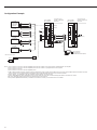
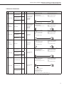
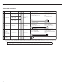
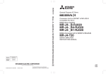
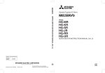
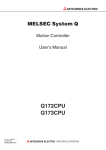
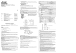
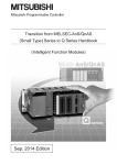
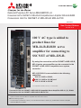
General-Purpose AC Servo MELSERVO-J4
Conversion Unit for SSCNET of MR-J2S-B Compatible Servo Amplifier: MR-J4-B-RJ020
Conversion Unit for SSCNET of MR-J2S-B: MR-J4-T20
March 2014
New Product Release
S V 1 3 06 - 1 E- B
100 V AC type is added to
product lines for
MR-J4-B-RJ020 servo
amplifier for connecting to
SSCNET of MR-J2S-B.
By using the conversion unit for SSCNET of MR-J2S-B,
MR-J4 series servo amplifier can be connected to the
SSCNET of MR-J2S-B compatible servo system
controller *.
MR-J4-B-RJ020 is now available in the following
capacities:
200 V 0.1 kW to 22 kW,
NEW 100 V 0.1 kW to 0.4 kW, and
400 V 0.6 kW to 22 kW
* For compatible controllers, refer to p. 1 in this brochure.
Conversion Unit for SSCNET of MR-J2S-B Compatible Servo Amplifier: MR-J4-_B_-RJ020
Conversion Unit for SSCNET of MR-J2S-B: MR-J4-T20
●A combination of MR-J4-B-RJ020 and MR-J4-T20 is capable of connecting to the SSCNET of MR-J2S-B compatible servo
system controller and drives MR-J4 compatible HG series servo motors.
●Use the existing program.
* For the outline of precautions, refer to p. 2 in this brochure. Refer to "MR-J4-_B_-RJ020 MR-J4-T20 Servo Amplifier
Instruction Manual" for details.
Features
A combination of MR-J4-B-RJ020 and MR-J4-T20 is capable of connecting to the SSCNET of MR-J2S-B compatible servo system
controller.
Thus, renewing a machine with MR-J4 series servo amplifiers and servo motors is possible without changing the existing controller.
MR-J2S-B system
MR-J4-B system
SSCNET of MR-J2S-B compatible controller
SSCNET III/H compatible controller
MR-J2S-B
MR-J4-B
Replacement
HC/HA series
HG series
lHigh-accuracy and high-response MR-J4-B system
lCompatible with high-speed optical communication SSCNET III/H
Equipment renewal
Renew the units other than the
controller to MR-J4 series using the
existing program.
Refer to "MELSERVO-J4
catalog L(NA)03058" for details.
Renew the controller in the future to
configure the MR-J4-B system.
MR-J4-B-RJ020 + MR-J4-T20
HG series servo motor
When renewing a machine with MR-J4 servo amplifiers and HG series servo motors
Maintenance
Replace the servo
amplifier without
changing the existing
connections.
SSCNET of MR-J2S-B compatible controller
This renewal is introduced in this brochure.
MR-J4-B-RJ020
MR-J4-T20
HG series
lA combination of MR-J4-B-RJ020 and
MR-J4-T20 is capable of connecting to the
SSCNET of MR-J2S-B compatible servo
system controller.
*The function and performance are equivalent to those of
MR-J2S-B. (J2S compatibility mode)
*Read the precautions on p. 2 in this brochure.
MR-J2S-B renewal tool manufactured by Mitsubishi Electric System & Service Co., Ltd.
When using the existing HC/HA series servo motors or when replacing MR-J2S-B using the existing connections
SSCNET of MR-J2S-B compatible controller
For MR-J2S-B renewal tool, contact your local sales office.
Renewal tool
MR-J4-B-RJ020
MR-J4-T20
L
L
L
U
V
W
lUse the existing mounting holes and wiring, and complete
the replacement and the wiring in a short period of time.
HC/HA series
Compatible Controllers
The set of MR-J4-B-RJ020 and MR-J4-T20 is compatible with the following servo system controllers:
A171SHCPU(N), A172SHCPU(N), A173UHCPU, A1SD75M, QD75M, Q172CPU(N), and Q173CPU(N)
1
MR-J4-B-RJ020 Connections with Peripheral Equipment
Axis setting part (Note 3)
Display (Note 3)
Select an axis with the axis selection rotary switch (SW1).
The control axis setting switches (SW2) are not for use in
the J2S compatibility mode. Set all to "off (bottom)."
Servo amplifier
status and alarm
number are
displayed.
Molded-case circuit breaker
(MCCB)
This protects the power supply line.
(Note 1, 2)
USB communication connector (CN5)
This connector is not for use in the J2S compatibility mode.
I/O signal connector (CN3)
This connector is used for forced stop input and electromagnetic brake
interlock signals. The signal wiring is partially different from that of MR-J2S-B.
Refer to "MR-J4-_B_-RJ020 MR-J4-T20 Servo Amplifier Instruction Manual."
When using digital I/O signal, 24 V power supply is separately required as an
interface power supply.
Magnetic contactor (MC)
This turns off the power to the servo
amplifier when an alarm is triggered.
Compatible servo system controller
A171SHCPU(N), A172SHCPU(N),
A173UHCPU, A1SD75M, QD75M,
Q172CPU(N), Q173CPU(N)
Power factor improving DC reactor (optional)
This boosts the power factor of servo
amplifier and reduces the power
supply capacity.
Regenerative option
(optional)
Connector for SSCNET cable
connection (CN10A)
(Note 4)
(Note 5)
Connect the servo system controller
or the previous servo amplifier axis.
Servo motor power cable (optional)
Charge lamp
Connector for SSCNET cable
connection (CN10B)
The lamp lights when the main circuit power
supply is charged.
Connect the next servo amplifier axis or
MR-A-TM terminal connector.
Encoder connector (CN2)
Connect the servo motor encoder using an
optional cable or a connector set.
Manufacturer setting connector (CN2L)
RS-232C communication connector
(CN30)
This connector is not for use.
Connect a personal computer and perform
parameter setting and monitoring with
MR Configurator. Use optional RS-232C cable
(MR-CPCATCBL3M) with junction cable
(MR-J4T20CH00).
Battery connector (CN4)
Connect MR-BAT6V1SET battery when
configuring absolute position detection
system.
Battery
Encoder cable (optional)
MR Configurator
(Setup software)
MRZJW3-SETUP161E (Note 6)
Servo motor
(The picture is as of HG-KR053.)
Notes:1.The connection with the peripheral equipment is an example for 3.5 kW or smaller servo amplifiers. Refer to "MR-J4-_B_-RJ020
MR-J4-T20 Servo Amplifier Instruction Manual" for the actual connections.
2.When MR-J4-_B_-RJ020 is used with MR-J4-T20, the mode is the J2S compatibility mode.
3.This picture shows when the display cover is open.
4.This connector is not for use in the J2S compatibility mode. Be sure to attach a short-circuit connector supplied with the servo amplifier.
5.This connector is not for use in the J2S compatibility mode. Be sure to attach a cap supplied with the servo amplifier.
6.Setup software (MRZJW3-SETUP161E) is available for free download. Contact your local sales office for more details.
Precautions
Installation
lMounting holes are not compatible with those of MR-J2S-_B_.
lDimensions of MR-J4-_B_ combined with MR-J4-T20 are different from
those of MR-J2S-_B_.
Wiring
lThe wire size is different from that of MR-J2S-_B_ depending on the capacity.
lOptions/peripheral equipment for MR-J2S series cannot be used except
the SSCNET cable and the terminal connector. Select options/ peripheral
equipment for MR-J4 series.
lFor RS-232C communication, use RS-232C cable (MR-CPCATCBL3M)
with junction cable (MR-J4T20CH00).
lMR-J4-_B_-RJ020 servo is not equipped with 24 V power supply for
interface. When using digital I/O signal, 24 V (current capacity 0.1 A) power
supply is separately required as an interface power supply.
lThe signal wiring of connector for I/O signal (CN3) of MR-J4-_B_-RJ020 is
partially different from that of MR-J2S-_B_.
lUse MR-BAT6V1SET when configuring absolute position detection system.
Function/performance
lAdaptive vibration suppression control (parameter No. 25) is not available.
lAlarms are displayed in two digits, which is the same as MR-J2S-_B_.
Some alarms are displayed in three digits.
lUse MR Configurator (MRZJW3-SETUP161E). Note that the following
functions are not available.
- Gain search
- Machine simulation
- Motor-less operation (Motor-less operation by the parameter setting is available.)
lServo motors that are compatible with MR-J4 (HG series) may have
different coasting distance for dynamic brake from that of conventional
HC/HA series servo motors.
lThe encoder resolution of HG series servo motors will be 131072
pulses/rev (17 bit).
Refer to "MR-J4-_B_-RJ020 MR-J4-T20 Servo Amplifier Instruction Manual" for details.
2
Servo Amplifier Model Designation
MR-J4-10 B
-RJ020
Symbol
Mitsubishi
generalpurpose AC
servo amplifier
MELSERVO-J4
Series
RJ020
Symbol
Interface
B
SSCNET III/H (Note 3)
Symbol
10
20
40
60
70
100
200
350
500
700
11K
15K
22K
Rated output [kW]
0.1
0.2
0.4
0.6
0.75
1
2
3.5
5
7
11
15
22
Symbol
None
1
4
Power supply
3-phase 200 V AC or
1-phase 200 V AC (Note 1)
1-phase 100 V AC (Note 7)
3-phase 400 V AC (Note 2)
RU020
RZ020
Special specification
Conversion unit for SSCNET of
MR-J2S-B compatible (Note 5)
MR-J4-_B_-RJ020 without
a dynamic brake (Note 4, 5)
MR-J4-_B_-RJ020 without an
enclosed regenerative resistor
(Note 5, 6)
Notes:1.0.75 kW or smaller servo amplifiers are available for 1-phase 200 V AC.
2.0.6 kW, and 1 kW or larger servo amplifiers are available.
3. SSCNET III/H interface is not available in the J2S compatibility mode.
4.Available in 7 kW or less servo amplifier without a built-in dynamic brake.When using the servo amplifier without a dynamic brake, the servo motor does not stop
immediately at an alarm occurrence or power failure. Take measures to ensure safety on the entire system.
When the following servo motors are used, the electronic dynamic brake may operate at an alarm occurrence.
HG-KR053, HG-KR13, HG-KR23, HG-KR43, HG-MR053, HG-MR13, HG-MR23, HG-MR43, HG-SR51, and HG-SR52
Disable the electronic dynamic brake by setting [Pr. 56] to "2_ _ _."
5.MR-J4-T20 conversion unit for SSCNET of MR-J2S-B is required to make the servo amplifier be compatible with SSCNET interface.
When MR-J4-B-RJ020 and MR-J4-T20 are combined, MR-J4-B-RJ020 is compatible with the following servo system controllers:
A171SHCPU(N), A172SHCPU(N), A173UHCPU, A1SD75M, QD75M, Q172CPU(N), and Q173CPU(N)
6. Available in 11 kW to 22 kW servo amplifier. A regenerative resistor (standard accessory) is not enclosed.
7. 0.4 kW or smaller servo amplifiers are available.
3
Conversion Unit for SSCNET of MR-J2S-B Compatible Servo Amplifier: MR-J4-B-RJ020
Conversion Unit for SSCNET of MR-J2S-B: MR-J4-T20
Combinations of Servo Amplifier and Servo Motor
For 200 V AC/100 V AC
Servo amplifier
MR-J4-10B-RJ020
MR-J4-10B1-RJ020
MR-J4-20B-RJ020
MR-J4-20B1-RJ020
MR-J4-40B-RJ020
MR-J4-40B1-RJ020
MR-J4-60B-RJ020
MR-J4-70B-RJ020
MR-J4-100B-RJ020
MR-J4-200B-RJ020
MR-J4-350B-RJ020
MR-J4-500B-RJ020
MR-J4-700B-RJ020
MR-J4-11KB-RJ020
MR-J4-15KB-RJ020
MR-J4-22KB-RJ020
Servo motor
HG-KR053, 13
HG-MR053, 13
HG-KR23
HG-MR23
HG-KR43
HG-MR43
HG-SR51, 52
HG-JR53
HG-KR73
HG-MR73
HG-JR73
HG-UR72
HG-SR81, 102
HG-JR53 (Note 1), 103
HG-SR121, 201, 152, 202
HG-JR73 (Note 1), 103 (Note 1), 153, 203
HG-RR103, 153
HG-UR152
HG-SR301, 352
HG-JR153 (Note 1), 203 (Note 1), 353
HG-RR203
HG-UR202
HG-SR421, 502
HG-JR353 (Note 1), 503
HG-RR353, 503
HG-UR352, 502
HG-SR702
HG-JR503 (Note 1), 703
HG-JR903, 11K1M
HG-JR15K1M
HG-JR22K1M
For 400 V AC
Servo amplifier
MR-J4-60B4-RJ020
MR-J4-100B4-RJ020
MR-J4-200B4-RJ020
MR-J4-350B4-RJ020
MR-J4-500B4-RJ020
MR-J4-700B4-RJ020
MR-J4-11KB4-RJ020
MR-J4-15KB4-RJ020
MR-J4-22KB4-RJ020
Servo motor
HG-SR524
HG-JR534
HG-SR1024
HG-JR534 (Note 1), 734, 1034
HG-SR1524, 2024
HG-JR734 (Note 1), 1034 (Note 1), 1534,
2034
HG-SR3524
HG-JR1534 (Note 1), 2034 (Note 1), 3534
HG-SR5024
HG-JR3534 (Note 1), 5034
HG-SR7024
HG-JR5034 (Note 1), 7034
HG-JR9034, 11K1M4
HG-JR15K1M4
HG-JR22K1M4
Notes: 1. The maximum torque can be increased from 300% to 400% of the rated torque with this combination.
4
MR-J4-B-RJ020 (Interface for SSCNET of MR-J2S-B) Specifications (200 V/100 V)
Servo amplifier model MR-J4-_-RJ020 10B 20B 40B
Rated voltage
Output
Rated current
[A] 1.1 1.5 2.8
Main
circuit
power
supply
input
Control
circuit
power
supply
input
Voltage/frequency (Note 1)
Rated current
Permissible voltage
fluctuation
Permissible frequency
fluctuation
70B 100B 200B 350B 500B 700B 11KB 15KB 22KB 10B1 20B1 40B1
3-phase 170 V AC
3.2
5.8 6.0 11.0 17.0 28.0 37.0 68.0 87.0 126.0 1.1 1.5 2.8
1-phase 100 V AC
3-phase or 1-phase 200 V AC
3-phase 200 V AC to 240 V AC, 50 Hz/60 Hz
to 120 V AC,
to 240 V AC, 50 Hz/60 Hz
50 Hz/60 Hz
[A] 0.9 1.5 2.6 3.2 (Note 7) 3.8 5.0 10.5 16.0 21.7 28.9 46.0 64.0 95.0 3.0 5.0 9.0
3-phase or 1-phase 170 V AC
1-phase 85 V AC
3-phase 170 V AC to 264 V AC
to 264 V AC
to 132 V AC
±5% maximum
Voltage/frequency
Rated current
Permissible voltage
fluctuation
Permissible frequency
fluctuation
Power consumption
Interface power supply
Control method
Built-in regenerative
resistor (Note 2, 3)
Tolerable
regenerative
External regenerative
power
resistor (standard
accessory) (Note 2, 3, 9, 10)
Dynamic brake
Communication function
Encoder output pulse
Analog monitor
Fully closed loop control
Load-side encoder interface
[A]
0.3
±5% maximum
[W]
30
45
24 V DC ± 10% (required current capacity: 0.1 A)
Sine-wave PWM control/current control method
[W]
-
10
10
10
20
20
100
100
130
170
[W]
-
-
-
-
-
-
-
-
-
-
CE marking
UL standard
CSA standard
Korea Radio Wave
Law (KC)
Close mounting
Ambient temperature
Ambient humidity
Environment Ambience
Altitude
Vibration resistance
Mass (Note 8)
0.2
1-phase 170 V AC to 264 V AC
Functional safety
Structure (IP rating)
1-phase 100 V AC
to 120 V AC,
50 Hz/60 Hz
0.4
1-phase 85 V AC
to 132 V AC
1-phase 200 V AC to 240 V AC, 50 Hz/60 Hz
Protective functions
Compliance to
standards
60B
-
-
30
-
500 850
850
(800) (1300) (1300)
-
10
10
-
-
-
Built-in (Note 4)
External option (Note 11)
Built-in (Note 4)
USB: not for use in the J2S compatibility mode
Compatible (A/B/Z-phase pulse)
2 channels
Not compatible
Not compatible
Overcurrent shut-off, regenerative overvoltage shut-off, overload shut-off (electronic thermal), servo
motor overheat protection, encoder error protection, regenerative error protection, undervoltage
protection, instantaneous power failure protection, overspeed protection, error excessive protection
Not compatible
LVD: EN 61800-5-1
EMC: EN 61800-3
MD: EN ISO 13849-1, EN 61800-5-2, EN 62061
UL 508C
CSA C22.2 No.14
Compliant
Natural cooling, open
Force cooling, open
Force cooling, open
Natural cooling,
(IP20)
(IP20)
(IP20) (Note 5)
open (IP20)
Possible (Note 6)
Not possible
Possible (Note 6)
0 °C to 55 °C (non-freezing), storage: -20 °C to 65 °C (non-freezing)
90 %RH maximum (non-condensing), storage: 90 %RH maximum (non-condensing)
Indoors (no direct sunlight); no corrosive gas, inflammable gas, oil mist or dust
1000 m or less above sea level
5.9 m/s2 at 10 Hz to 55 Hz (directions of X, Y and Z axes)
[kg] 0.8 0.8 1.0
1.0
1.4 1.4 2.1 2.3 4.0 6.2 13.4 13.4 18.2 0.8 0.8 1.0
Notes:1.Rated output and speed of a rotary servo motor are applicable when the servo amplifier, combined with the rotary servo motor, is operated within the specified power
supply voltage and frequency.
2.Select the most suitable regenerative option for your system with our capacity selection software.
3.Refer to "MR-J4-_B_-RJ020 MR-J4-T20 Servo Amplifier Instruction Manual" for the tolerable regenerative power [W] when regenerative option is used.
4.When using the built-in dynamic brake, refer to "MR-J4-_B_-RJ020 MR-J4-T20 Servo Amplifier Instruction Manual" for the permissible load to motor inertia ratio.
5.Terminal blocks are excluded.
6.When the servo amplifiers are closely mounted, keep the ambient temperature within 0 °C to 45 °C, or use them with 75% or less of the effective load ratio.
7.The rated current is 2.9 A when the servo amplifier is used with UL or CSA compliant servo motor.
8.The value is applicable for MR-J4-_B-RJ020 servo amplifier only.
9.The value in brackets is applicable when cooling fans (2 units of 92 mm × 92 mm, minimum air flow: 1.0 m3/min) are installed, and then [Pr. 2] is changed.
10.Servo amplifiers without an enclosed regenerative resistor are also available. Refer to "Servo Amplifier Model Designation" in this brochure for details.
11.Use an optional external dynamic brake with the servo amplifier. Without the external dynamic brake, a servo motor does not stop immediately at emergency stop and falls
in free-run status, causing an accident such as machine collision, etc. Take measures to ensure safety on the entire system when not using the dynamic brake.
5
Conversion Unit for SSCNET of MR-J2S-B Compatible Servo Amplifier: MR-J4-B-RJ020
Conversion Unit for SSCNET of MR-J2S-B: MR-J4-T20
MR-J4-B4-RJ020 (Interface for SSCNET of MR-J2S-B) Specifications (400 V)
Servo amplifier model MR-J4-_-RJ020
Rated voltage
Output
Rated current
[A]
Voltage/frequency (Note 1)
Main
Rated current
[A]
circuit
Permissible
voltage
power
fluctuation
supply
Permissible frequency
input
fluctuation
Voltage/frequency
[A]
Control Rated current
circuit
Permissible voltage
power
fluctuation
supply
Permissible frequency
input
fluctuation
Power consumption
[W]
Interface power supply
Control method
Built-in regenerative
resistor (Note 2, 3)
Tolerable
regenerative
External regenerative
power
resistor (standard
accessory) (Note 2, 3, 8, 9)
Dynamic brake
Communication function
Encoder output pulse
Analog monitor
Fully closed loop control
Load-side encoder interface
1.5
2.8
1.4
2.5
200B4
350B4
500B4
700B4
11KB4
3-phase 323 V AC
5.4
8.6
14.0
17.0
32.0
3-phase 380 V AC to 480 V AC, 50 Hz/60 Hz
5.1
7.9
10.8
14.4
23.1
15KB4
22KB4
41.0
63.0
31.8
47.6
3-phase 323 V AC to 528 V AC
±5% maximum
1-phase 380 V AC to 480 V AC, 50 Hz/60 Hz
0.2
0.1
1-phase 323 V AC to 528 V AC
±5% maximum
30
45
24 V DC ± 10% (required current capacity: 0.1 A)
Sine-wave PWM control/current control method
15
15
100
100
130 (Note 6)
170 (Note 6)
-
-
-
[W]
-
-
-
-
-
-
500
(800)
850
(1300)
850
(1300)
Functional safety
CE marking
UL standard
CSA standard
Korea Radio Wave
Law (KC)
Structure (IP rating)
Close mounting
Ambient temperature
Ambient humidity
Environment Ambience
Altitude
Vibration resistance
Mass (Note 7)
100B4
[W]
Protective functions
Compliance to
standards
60B4
[kg]
Built-in (Note 4)
External option (Note 10)
USB: not for use in the J2S compatibility mode
Compatible (A/B/Z-phase pulse)
2 channels
Not compatible
Not compatible
Overcurrent shut-off, regenerative overvoltage shut-off, overload shut-off (electronic thermal), servo
motor overheat protection, encoder error protection, regenerative error protection, undervoltage
protection, instantaneous power failure protection, overspeed protection, error excessive protection
Not compatible
LVD: EN 61800-5-1
EMC: EN 61800-3
MD: EN ISO 13849-1, EN 61800-5-2, EN 62061
UL 508C
CSA C22.2 No.14
Compliant
Natural cooling, open
(IP20)
1.7
Force cooling, open
(IP20)
Force cooling, open (IP20) (Note 5)
Not possible
0 °C to 55 °C (non-freezing), storage: -20 °C to 65 °C (non-freezing)
90 %RH maximum (non-condensing), storage: 90 %RH maximum (non-condensing)
Indoors (no direct sunlight); no corrosive gas, inflammable gas, oil mist or dust
1000 m or less above sea level
5.9 m/s2 at 10 Hz to 55 Hz (directions of X, Y and Z axes)
1.7
2.1
3.6
4.3
6.5
13.4
13.4
18.2
Notes:1.Rated output and speed of a rotary servo motor are applicable when the servo amplifier, combined with the rotary servo motor, is operated within the specified power supply
voltage and frequency.
2.Select the most suitable regenerative option for your system with our capacity selection software.
3.Refer to "MR-J4-_B_-RJ020 MR-J4-T20 Servo Amplifier Instruction Manual" for the tolerable regenerative power [W] when regenerative option is used.
4.When using the built-in dynamic brake, refer to "MR-J4-_B_-RJ020 MR-J4-T20 Servo Amplifier Instruction Manual" for the permissible load to motor inertia ratio.
5.Terminal blocks are excluded.
6.The servo amplifier built-in regenerative resistor is compatible with the maximum torque deceleration when the servo motor is used within the rated speed and the
recommended load to motor inertia ratio. Contact your local sales office if the operating motor speed or the load to motor inertia ratio exceeds the rated speed or the
recommended ratio.
7.The value is applicable for the MR-J4-_B4-RJ020 servo amplifier only.
8.The value in brackets is applicable when cooling fans (2 units of 92 mm × 92 mm, minimum air flow: 1.0 m3/min) are installed, and then [Pr. 2] is changed.
9.Servo amplifiers without an enclosed regenerative resistor are also available. Refer to "Servo Amplifier Model Designation" in this brochure for details.
10.Use an optional external dynamic brake with the servo amplifier. Without the external dynamic brake, a servo motor does not stop immediately at emergency stop and falls
in free-run status, causing an accident such as machine collision, etc. Take measures to ensure safety on the entire system when not using the dynamic brake.
6
Conversion Unit for SSCNET of MR-J2S-B (MR-J4-T20)
Specifications
Model
Item
Control circuit Voltage
power supply
Rated
input
current
Network interface
Description
MR-J4-T20
5 V DC
(Control circuit power for the conversion unit for SSCNET of MR-J2S-B is supplied from the servo amplifier.)
[A]
Communication function
Structure (IP rating)
Ambient
temperature
Ambient
humidity
Environment
Ambience
Altitude
Vibration
resistance
Mass
[g]
0.1
SSCNET interface (CN10A and CN10B connectors)
RS-232C: Connect a personal computer (MR Configurator (MRZJW3-SETUP161E) compatible) (CN30
connector)
Natural cooling, open (IP00)
0 °C to 55 °C (non-freezing), storage: -20 °C to 65 °C (non-freezing)
90 %RH maximum (non-condensing), storage: 90 %RH maximum (non-condensing)
Indoors (no direct sunlight); no corrosive gas, inflammable gas, oil mist or dust
1000 m or less above sea level
5.9 m/s2 at 10 Hz to 55 Hz (directions of X, Y and Z axes)
140
Dimensions
103.7
20
98.7
94.9
12
5x6 mounting hole for
grounding
MR-J4-T20
97
161
CN10B
114.5
CN10A
24.5
CN30
7
Conversion Unit for SSCNET of MR-J2S-B Compatible Servo Amplifier: MR-J4-B-RJ020
Conversion Unit for SSCNET of MR-J2S-B: MR-J4-T20
MR-J4-B-RJ020 Standard Wiring Diagram Example (Note 11)
Servo amplifier
MR-J4-B-RJ020
Main circuit
power supply
Main/control circuit power supply connection
The connection differs according to the power voltage.
Refer to "MR-J4-_B_-RJ020 MR-J4-T20 Servo
Amplifier Instruction Manual."
Control circuit
power supply
Servo motor connection
L1
U
L3
W
V
L2
Output voltage: ±10 V
Maximum output current: 1 mA
Output voltage: ±10 V
Maximum output current: 1 mA
2 m or shorter
10 m or shorter
(Note 5)
Main circuit power supply
Forced stop
10 m or shorter
R
A
1
4
1
14
SD
CN2L
CN8
Plate
EM1
DOCOM
20
3
DICOM
MBR
10
13
1
2
(Note 4)
1
Controller (Note 1)
4
0
CN9
CN70
CN90
(Note 8, 9)
SSCNET cable
This connector is not for use in the J2S compatibility
mode. Be sure to attach a short-circuit connector
supplied with the servo amplifier.
CN4
Mount an optional battery
(MR-BAT6V1SET) for absolute position
detection system.
BAT
LG
This connector is not for use in the J2S
compatibility mode. Be sure to attach a
cap supplied with the servo amplifier.
This connector is not for use in the J2S
compatibility mode. Be sure to attach a
cap supplied with the servo amplifier.
Servo amplifier (Note 2)
MR-J4-T20
Cable clamp
Personal computer
2nd axis
MR-J4-T20
CN10A
CN10B
Servo amplifier (Note 2)
nth axis (n = 1 to 8)
CN30
MR Configurator
(Setup software)
MRZJW3-SETUP161E
(Note 10)
3
CN7
CN10A
• A171SHCPU(N)
• A172SHCPU(N)
• A173UHCPU
• A1SD75M
• QD75M
• Q172CPU(N)
• Q173CPU(N)
2
This connector is not for use.
This connector is not for use in the J2S compatibility mode.
(Note 7) (Note 3)
SW2
SW1
10 m or shorter
Servo motor
CN10B
Electromagnetic brake interlock
MO1
LG
MO2
Encoder cable
CN5
Analog monitor output
5
3
8
18
6
16
7
17
11
CN1B
Encoder Z-phase pulse
(differential line driver)
Encoder A-phase pulse
(differential line driver)
Encoder B-phase pulse
(differential line driver)
Control common
DICOM
DOCOM
LZ
LZR
LA
LAR
LB
LBR
LG
CN2
CN1A
CN3
Power cable
L11
L21
(Note 6)
24 V DC power supply for interface
The connection differs according to each servo motor.
Refer to "MR-J4-_B_-RJ020 MR-J4-T20 Servo Amplifier
Instruction Manual."
MR-J4-T20
CN10A
RS-232C junction cable
(MR-J4T20CH00)
RS-232C cable
(MR-CPCATCBL3M)
CN10B
Be sure to attach MR-A-TM terminal connector
to CN10B connector of the final axis.
(Note 8, 9)
SSCNET cable
Be sure to read through Instruction Manual for the actual wiring and use. Use the equipment after you have a full knowledge
of the equipment, safety information and instructions.
8
MR-J4-B-RJ020 Standard Wiring Diagram Example
Notes:1.For details such as setting the controllers, refer to programming manual or user's manual for the controllers.
2.Connections for the second and following axes are omitted.
3.Up to 8 axes are connectable by setting the axis selection rotary switch (SW1).
4.This is for sink wiring. Source wiring is also possible.
5.Create a circuit to turn off EM1 (Forced stop) when the main circuit power is turned off to prevent an unexpected restart of the servo amplifier.
6.Provide an external power supply of 24 V DC ± 10% (required current capacity: 0.1 A) to the interface.
7.SW2 is not for use in the J2S compatibility mode.
8.The total length of the SSCNET cables must be 30 m or shorter. It is recommended that three or four data line filters in serial connection or a cable cramp be used near the
connector on the controller to improve noise immunity.
9.The SSCNET cables vary depending on the controller. Select the appropriate SSCNET cable as follows:
• A171SHCPU(N)/A172SHCPU(N)/A173UHCPU/A1SD75M: MR-J2HBUS_M-A
• QD75M: MR-J2HBUS_M
• Q172CPU(N): Q172J2BCBL_M(-B)
• Q173CPU(N): Q173J2B_CBL_M
• MR-J4-_B_-RJ020+MR-J4-T20: MR-J2HBUS_M
10.Use setup software (MRZJW3-SETUP161E) when using MR-J4-_B_-RJ020 servo amplifier in the J2S compatibility mode.
Setup software (MRZJW3-SETUP161E) is available for free download. Contact your local sales office for more details.
11.This standard wiring diagram is common for 200 V AC, 100 V AC and 400 V AC type servo amplifiers.
9
Conversion Unit for SSCNET of MR-J2S-B Compatible Servo Amplifier: MR-J4-B-RJ020
Conversion Unit for SSCNET of MR-J2S-B: MR-J4-T20
MR-J4-B-RJ020 Dimensions (Note 2)
●●MR-J4-10B-RJ020 (Note 1), MR-J4-10B1-RJ020 (Note 1)
●●MR-J4-20B-RJ020 (Note 1), MR-J4-20B1-RJ020 (Note 1)
52
6
Terminal arrangement
L1
Approx. 80
L1
135
L2
CNP1
CNP1
N-
C
N
3
P3
CNP3
P+
C
D
L11
L21
P4
C
N
1
A
U
C
N
1
B
V
W
Mounting screw size: M5
P4
C
N
8
161
CNP2
P+
168
N-
Screw size: M4
P3
CN10A
L3
156
L3
CNP1
N-
C
N
5
L1
L2
PE
L2
6
ø6 mounting hole
Terminal arrangement
40
CNP2
CN10B
C C
N N
2 3
C 0
N
2
L
(21)
6
D
L11
L11
L21
L21
U
CNP3
(69.3)
PE
(38.5)
C
CNP2
D
C
N
4
6
P+
C
When mounting
MR-BAT6V1SET
U
CNP3
V
V
W
W
For 1-phase 100 V AC
For 3-phase 200 V AC
or 1-phase 200 V AC
[Unit: mm]
4
●●MR-J4-40B-RJ020 (Note 1), MR-J4-40B1-RJ020 (Note 1)
●●MR-J4-60B-RJ020 (Note 1)
52
6
Terminal arrangement
Approx. 80
L1
L1
170
CNP1
CNP1
C
N
5
C
N
3
N-
CNP2
P3
CNP3
P+
C
D
L11
L21
P4
C
N
1
A
W
N-
Screw size: M4
Mounting screw size: M5
P4
P+
P+
C
C
N
1
B CN10B
V
L3
CNP1
N-
P3
C
N
8
U
L2
CN10A
161
156
L3
168
L1
L2
PE
L2
6
ø6 mounting hole
Terminal arrangement
40
CNP2
C C
N N
2 3
C 0
N
2
L
(21)
6
C
N
4
(38.5)
D
L11
L11
L21
L21
U
CNP3
(69.3)
PE
6
C
CNP2
D
When mounting
MR-BAT6V1SET
U
CNP3
V
V
W
W
For 1-phase 100 V AC
For 3-phase 200 V AC
or 1-phase 200 V AC
[Unit: mm]
5
●●MR-J4-70B-RJ020 (Note 1)
●●MR-J4-100B-RJ020 (Note 1)
72
12
ø6 mounting hole
60
Approx. 80
185
Terminal arrangement
Exhaust
6
L1
CNP1
156
C
N
3
P3
P4
C
N
8
P+
C
D
L11
L21
CNP3
CN10A
C
N
1
A
U
CNP1
161
L3
N-
CNP2
6
12
(21)
(38.5)
42
Mounting screw size: M5
C
C
N
4
6
Screw size: M4
P+
C C
N N
2 3
C 0
N
2
L
PE
NP4
C
N
1
B CN10B
V
W
PE
L3
P3
168
L2
CNP2
L2
C
N
5
L1
When mounting
MR-BAT6V1SET
(69.3)
Intake
Cooling fan
D
L11
L21
U
CNP3
V
W
6
[Unit: mm]
Notes:1.CNP1, CNP2 and CNP3 connectors (insertion type) are supplied with the servo amplifier.
2.The dimensions are applicable when MR-J4-B-RJ020 and MR-J4-T20 are combined. Refer to "MR-J4-B(-RJ) Dimensions" in "MELSERVO-J4 catalog (L(NA)03058)" for
the dimensions of MR-J4-B-RJ020 servo amplifiers alone.
10
MR-J4-B-RJ020 Dimensions (Note2)
●●MR-J4-60B4-RJ020 (Note1)
●●MR-J4-100B4-RJ020 (Note1)
72
60
12
ø6 mounting hole
Approx. 80
195
Terminal arrangement
6
N-
CNP1
156
L3
P3
C
N
8
P4
C
N
1
A
P+
C
D
CNP3
CNP1
CN10A
161
C
N
3
L2
L21
U
(21)
PE
6
D
L11
When mounting
MR-BAT6V1SET
L21
(69.3)
(38.5)
12
Mounting screw size: M5
C
CNP2
6
W
Screw size: M4
P+
C C
N N
2 3
C 0
N
2
L
C
N
4
V
L3
P4
C
N
1
B CN10B
L11
PE
L2
P3
168
L1
CNP2
L1
C
N
5
N-
U
42
CNP3
V
W
[Unit: mm]
6
●●MR-J4-200B-RJ020 (Note 1)
ø6 mounting hole
45
97
85
Approx. 80
Terminal arrangement
195
6
Exhaust
L1
L2
CNP1
C
N
5
L1
L2
L3
C
N
3
N-
CNP1
CN10A
P3
CNP3
P4
C
N
8
P+
C
D
L11
L21
C
N
1
A
Mounting screw size: M5
C
CNP2
(21)
6
PE
(38.5)
6
6
Screw size: M4
P+
C C
N N
2 3
C 0
N
2
L
V
W
NP4
C
N
1
B CN10B
U
L3
P3
161
168
156
CNP2
PE
(69.3)
When mounting
MR-BAT6V1SET
6
78
Intake
D
L11
Cooling fan
L21
U
CNP3
V
W
6
[Unit: mm]
●●MR-J4-200B4-RJ020 (Note 1)
ø6 mounting hole
45
97
85
Approx. 80
195
Terminal arrangement
NL1
CNP1
C
N
5
NL1
C
N
3
L2
L3
CNP2
156
P3
C
N
8
P4
C
N
1
A
P+
C
CNP3
D
CNP1
CN10A
L21
U
6
(21)
(38.5)
6
78
Mounting screw size: M5
C
CNP2
6
PE
Screw size: M4
P+
C C
N N
2 3
C 0
N
2
L
C
N
4
V
W
L3
P4
C
N
1
B CN10B
L11
PE
L2
P3
161
168
6
Exhaust
6
When mounting
MR-BAT6V1SET
(69.3)
Intake
Cooling fan
D
L11
L21
U
CNP3
V
W
6
[Unit: mm]
Notes:1.CNP1, CNP2 and CNP3 connectors (insertion type) are supplied with the servo amplifier.
2.The dimensions are applicable when MR-J4-B-RJ020 and MR-J4-T20 are combined. Refer to "MR-J4-B(-RJ) Dimensions" in "MELSERVO-J4 catalog (L(NA)03058)" for
the dimensions of MR-J4-B-RJ020 servo amplifiers alone.
11
Conversion Unit for SSCNET of MR-J2S-B Compatible Servo Amplifier: MR-J4-B-RJ020
Conversion Unit for SSCNET of MR-J2S-B: MR-J4-T20
MR-J4-B-RJ020 Dimensions (Note 2)
●●MR-J4-350B-RJ020 (Note 1)
Mounting hole
45
97
85
Approx. 80
Terminal arrangement
195
Exhaust
6
L1
L2
CNP1
C
N
5
C
N
3
L2
L3
N-
156
)
C
N
8
P3
P4
C
N
1
A
U
CNP2
(R
V
W
L3
NP3
Mounting hole
dimensions
C C
N N
2 3
0
U
CNP3
(21)
6
C
N
2
L
C
N
4
PE
6
78
6
Intake
Cooling fan
(69.3)
When mounting
MR-BAT6V1SET
(38.5)
6
P+
P4
ø13 hole
C
N
1
B CN10B
P+
C
D
L11
L21
6
CNP1
161
168
CNP3
CN10A
10
L1
C
CNP2
D
V
L11
W
L21
PE
Screw size: M4
Mounting screw size: M5
6
●●MR-J4-350B4-RJ020 (Note 1)
2-ø6 mounting hole
6
107
105
93
200
Approx. 80
(28)
6
6
Terminal arrangement
Cooling fan
Exhaust
7.5
[Unit: mm]
NL1
CNP1
CNP1
L2
L3
P3
CNP2
235
P4
250
PE
Screw size: M4
Mounting screw size: M5
P+
CNP3
C
CNP2
6
D
L11
L21
Intake
PE
U
CNP3
V
W
(34) (38.5)
7.5
When mounting
MR-BAT6V1SET
[Unit: mm]
●●MR-J4-500B-RJ020
(25)
6
107
105
93
6
Approx. 80
(28)
200
6
Cooling fan
Exhaust
7.5
2-ø6 mounting
hole
Terminal diagram
(with front cover open)
Terminal arrangement
TE2
TE2
250
TE1
L2
L3
N-
TE3
P3
TE4
When mounting
MR-BAT6V1SET
PE
L1
TE1
235
L11
L21
TE3
P4
P+
Terminal screw size
TE1: M4
TE2: M3.5
TE3: M4
TE4: M4
PE: M4
Mounting screw size: M5
7.5
C
Intake
6
D
PE
(34) (38.5)
TE4
U
V
W
[Unit: mm]
Notes:1.CNP1, CNP2 and CNP3 connectors (insertion type) are supplied with the servo amplifier.
2.The dimensions are applicable when MR-J4-B-RJ020 and MR-J4-T20 are combined. Refer to "MR-J4-B(-RJ) Dimensions" in "MELSERVO-J4 catalog (L(NA)03058)" for
the dimensions of MR-J4-B-RJ020 servo amplifiers alone.
12
MR-J4-B-RJ020 Dimensions (Note 1)
●●MR-J4-500B4-RJ020
132
130
118
Approx. 80
200
(28)
Cooling fan
Exhaust
7.5
2-ø6 mounting
6
hole
6
Terminal diagram
(with front cover open)
Terminal screw size
TE1: M4
TE2: M3.5
TE3: M4
PE: M4
250
235
Mounting screw size: M5
TE3
TE2
TE1
When mounting
MR-BAT6V1SET
Terminal arrangement
TE2
L11 L21
TE3
N- P3 P4
TE1
7.5
Intake
L1 L2 L3 P+
PE
U
V
W
(60)
(38.5)
C
PE
Built-in regenerative
resistor lead terminal
fixing screw
[Unit: mm]
●●MR-J4-700B-RJ020
●●MR-J4-700B4-RJ020
6
174
172
160
7.5
2-ø6 mounting hole
6
Approx. 80
(28)
200
6
Cooling fan
Exhaust
Terminal diagram
(with front cover open)
Terminal screw size
TE1: M4
TE2: M3.5
TE3: M4
PE: M4
300
285
Mounting screw size: M5
When mounting
MR-BAT6V1SET
TE3
Terminal arrangement
TE3
Intake
6
PE
Built-in regenerative
resistor lead terminal
fixing screw
N- P3 P4
TE2
TE2
TE1
L1 L2 L3 P+
C
U
V
W
L11 L21
PE
(101)
(38.5)
7.5
TE1
[Unit: mm]
Notes:1.The dimensions are applicable when MR-J4-B-RJ020 and MR-J4-T20 are combined. Refer to "MR-J4-B(-RJ) Dimensions" in "MELSERVO-J4 catalog (L(NA)03058)" for
the dimensions of MR-J4-B-RJ020 servo amplifiers alone.
13
Conversion Unit for SSCNET of MR-J2S-B Compatible Servo Amplifier: MR-J4-B-RJ020
Conversion Unit for SSCNET of MR-J2S-B: MR-J4-T20
MR-J4-B-RJ020 Dimensions (Note 1)
●●MR-J4-11KB-RJ020
●●MR-J4-15KB-RJ020
●●MR-J4-11KB4-RJ020
●●MR-J4-15KB4-RJ020
220
196
12
(28)
10.5
Terminal diagram
(with front cover open)
Cooling fan
Exhaust
2-ø6 mounting hole
10
260
Terminal screw size
TE1-1: M6
TE1-2: M6
TE2: M4
PE: M6
380
400
Approx. 80
12
Mounting screw size: M5
PE
TE1-1
TE1-2
TE2
Terminal arrangement
TE1-1
L1 L2 L3
Intake
188
224.2
237.4
6
U
V
W
TE1-2
P3 P4 P+
C
N-
TE2
L11 L21
(38.5)
10
When mounting
MR-BAT6V1SET
(139.5)
PE
[Unit: mm]
●●MR-J4-22KB-RJ020
●●MR-J4-22KB4-RJ020
260
236
2-ø12 mounting hole
400
376
12
12
Approx. 80
12
(28)
260
Cooling fan
Exhaust
Terminal diagram
(with front cover open)
Terminal screw size
TE1-1: M8
TE1-2: M8
TE2: M4
PE: M8
When mounting
MR-BAT6V1SET
Mounting screw size : M10
TE2
TE1-1
TE1-2
Terminal arrangement
Intake
188.5
223.4
235.4
12
(38.5)
12
PE
TE1-1
L1 L2 L3
U
V
W
TE1-2
P3 P4 P+
C
N-
TE2
L11 L21
(179)
PE
[Unit: mm]
Notes: 1. The dimensions are applicable when MR-J4-B-RJ020 and MR-J4-T20 are combined. Refer to "MR-J4-B(-RJ) Dimensions" in "MELSERVO-J4 catalog (L(NA)03058)" for
the dimensions of MR-J4-B-RJ020 servo amplifiers alone.
14
Configuration Example
A171SHCPU(N)
A172SHCPU(N)
A173UHCPU
A1SD75M
Conversion unit for
SSCNET of MR-J2S-B
MR-J4-T20
Servo amplifier
MR-J4-B-RJ020
Controller
(1)
CNP1
(2)
Controller
QD75M
(Note 1)
(Note 5)
(3)
(4)
Controller
Q172CPU(N)
(5)
(6)
Controller
(Note 5)
(Note 2)
(Note 5)
CN5
(Note 4)
CN3
CN10A
CNP2
CNP3
(Note 3)
(Note 6)
CN2L
CN5
CN3
CN10A
CNP2
CN8
CN1A
CN10B
CNP3
(3)
CN1B
CN2
(Note 2)
CNP1
CN8
CN1A
Conversion unit for
SSCNET of MR-J2S-B
MR-J4-T20
Servo amplifier
MR-J4-B-RJ020
(4)
CN30
CN10B
CN1B
CN2
(10) (Note 8)
CN30
CN2L
(8)
CN4
CN4
(9)
Q173CPU(N)
(7)
MR Configurator
(Setup software)
MRZJW3-SETUP161E (Note 9)
HG series servo motor
(Note 7)
(Note 7)
Notes:1.This connector is not for use in the J2S compatibility mode. Be sure to attach a short-circuit connector supplied with the servo amplifier.
2.This connector is not for use in the J2S compatibility mode. Be sure to attach a cap supplied with the servo amplifier.
3.This connector is not for use.
4.This connector is not for use in the J2S compatibility mode.
5.CNP1, CNP2 and CNP3 connectors (insertion type) are supplied with 3.5 kW or smaller servo amplifiers. As 5 kW or larger servo amplifiers have terminal blocks mounted,
these connectors are not supplied with the servo amplifier. Refer to "MR-J4-B-RJ020 Dimensions" in this brochure for details.
6.Refer to "MR-J4-_B_-RJ020 MR-J4-T20 Servo Amplifier Instruction Manual" for CN3 connector.
7.Refer to "MELSERVO-J4 catalog (L(NA)03058)" for the encoder cable, the power cable, and the electromagnetic cable for HG series servo motors.
8.Be sure to attach MR-A-TM terminal connector to CN10B connector of the final axis.
9.Setup software (MRZJW3-SETUP161E) is available for free download. Contact your local sales office for more details.
15
Conversion Unit for SSCNET of MR-J2S-B Compatible Servo Amplifier: MR-J4-B-RJ020
Conversion Unit for SSCNET of MR-J2S-B: MR-J4-T20
Cables and Connectors
Item
Model
MR-J2HBUS05M-A
(1) SSCNET cable
SSCNET
(2)
connector set
(3) SSCNET cable
(4)
SSCNET
connector set
(5) SSCNET cable
(6) SSCNET cable
Cable
length
1m
MR-J2HBUS5M-A
5m
-
MR-J2HBUS05M
0.5 m
MR-J2HBUS1M
1m
MR-J2HBUS5M
5m
MR-J2CN1
-
Q172J2BCBL05M
0.5 m
Q172J2BCBL1M
1m
Q172J2BCBL5M
5m
Q172J2BCBL05M-B
0.5 m
Q172J2BCBL1M-B
1m
Q172J2BCBL5M-B
Application
0.5 m
MR-J2HBUS1M-A
MR-J2CN1-A
IP
rating
5m
-
-
-
-
-
-
For A171SHCPU(N)/
A172SHCPU(N)/
A173UHCPU/
A1SD75M/
MR-J4-T20
For A171SHCPU(N)/
A172SHCPU(N)/
A173UHCPU/
A1SD75M/
MR-J4-T20
For QD75M/
MR-J4-T20
For QD75M/
MR-J4-T20
Description
Controller-side connector
Connector: PCR-S20FS+
Case: PCR-LS20LA1
(Honda Tsushin Kogyo Co., Ltd.)
MR-J4-T20-side connector (Note 1)
Connector: 10120-6000EL
Shell kit: 10320-3210-000
(3M)
or an equivalent product
Controller-side connector
Connector: PCR-S20FS+
Case: PCR-LS20LA1
(Honda Tsushin Kogyo Co., Ltd.)
MR-J4-T20-side connector (Note 2)
Connector: 10120-3000PE
Shell kit: 10320-52F0-008
(3M)
or an equivalent product
Controller/MR-J4-T20-side
connector (Note 1)
Connector: 10120-6000EL
Shell kit: 10320-3210-000
(3M)
or an equivalent product
MR-J4-T20-side connector (Note 1)
Connector: 10120-6000EL
Shell kit: 10320-3210-000
(3M)
or an equivalent product
Controller/MR-J4-T20-side
connector (Note 2)
Connector: 10120-3000PE
Shell kit: 10320-52F0-008
(3M)
or an equivalent product
MR-J4-T20-side connector (Note 2)
Connector: 10120-3000PE
Shell kit: 10320-52F0-008
(3M)
or an equivalent product
Controller-side connector
Connector: HDR-E14MG1+
Case: HDR-E14LPA5
(Honda Tsushin Kogyo Co., Ltd.)
MR-J4-T20-side connector (Note 1)
Connector: 10120-6000EL
Shell kit: 10320-3210-000
(3M)
or an equivalent product
Controller-side connector
Connector: HDR-E14MG1+
Case: HDR-E14LPA5
(Honda Tsushin Kogyo Co., Ltd.)
MR-J4-T20-side connector (Note 1)
Connector: 10120-6000EL
Shell kit: 10320-3210-000
(3M)
or an equivalent product
For Q172CPU(N)/
MR-J4-T20
For Q172CPU(N)/
MR-J4-T20
Battery unit-side connector
Socket: HNC2-2.5S-2
Terminal: HNC2-2.5S-D-B
(Hirose Electric Co., Ltd.)
* Use this cable when using Q170BAT battery unit.
Notes:1.Solder type (connector: 10120-3000PE and shell kit: 10320-52F0-008) (3M) is also usable. Contact the manufacturer directly.
2.Press bonding type (connector: 10120-6000EL and shell kit: 10320-3210-000) (3M) is also usable. Contact the manufacturer directly.
16
Cables and Connectors
Item
Model
(7) SSCNET cable
(8)
(10)
Q173J2B_CBL05M (Note 2)
0.5 m
Q173J2B_CBL1M (Note 2)
1m
Q173J2B_CBL5M (Note 2)
5m
Junction cable for
MR-J4T20CH00
RS-232C
Personal
computer
(9) communication
cable
(RS-232C cable)
Terminal
connector
Cable
length
MR-CPCATCBL3M
MR-A-TM
0.2 m
IP
rating
-
-
Application
Description
Controller-side connector
Connector: HDR-E26MG1+
Case: HDR-E26LPA5
(Honda Tsushin Kogyo Co., Ltd.)
MR-J4-T20-side connector (Note 1)
Connector: 10120-6000EL
Shell kit: 10320-3210-000
(3M)
or an equivalent product
MR-J4-T20-side connector
Connector: HDR-E14MG1+
Case: HDR-E14LPA5
(Honda Tsushin Kogyo Co., Ltd.)
Junction connector
Receptacle: 10220-0200EL
Shell kit: 10320-E2W0-008
(3M) or an equivalent product
Junction connector (Note 1)
Connector: 10120-6000EL
Shell kit: 10320-3210-000
(3M) or an equivalent product
Personal computer connector
Connector: DE-9SF-N
Connector case: DE-C1-J6-S6
(Japan Aviation Electronics Industry,
Limited)
For Q173CPU(N)/
MR-J4-T20
For MR-J4-T20
3m
-
For MR-J4-T20
-
-
For MR-J4-T20
Notes:1.Solder type (connector: 10120-3000PE and shell kit: 10320-52F0-008) (3M) is also usable. Contact the manufacturer directly.
2.The underbar of Q173J2B_CBL05M/Q173J2B_CBL1M/Q173J2B_CBL5M indicates the number of SSCNET branched systems. None: one system, 2: two systems, 4: four
systems
Refer to "MR-J4-_B_-RJ020 MR-J4-T20 Servo Amplifier Instruction Manual" for the wire size and other options.
17
Conversion Unit for SSCNET of MR-J2S-B Compatible Servo Amplifier: MR-J4-B-RJ020
Conversion Unit for SSCNET of MR-J2S-B: MR-J4-T20
18
Safety Warning
To ensure proper use of the products listed in this catalog,
please be sure to read the instruction manual prior to use.
MDOC (1403)
New publication, effective March 2014
Specifications are subject to change without notice.