1
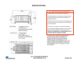
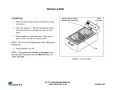
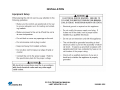
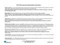
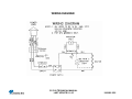
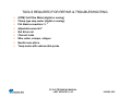
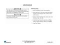
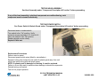
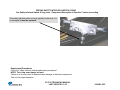
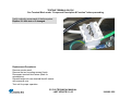
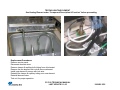
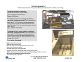
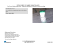
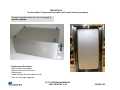
180 Kehoe Blvd. Carol Stream, Illinois 60188 USA 1-877-392-7854 (Tech Service). CCC-20 TECHNICAL MANUAL LAST UPDATE 5-1-05 1060005 5/05 CCC-20 TRAINING CCC-20 TECHNICAL MANUAL LAST UPDATE 5-1-05 1060005 5/05 CCC-20 SECTION •Warranty •Specifications •CCC warnings •CCC installation •CCC operating instructions •Technical theory of operation •Component description & functions •Wiring diagram •Tools required •CCC maintenance •Troubleshooting •Parts testing & replacement CCC-20 TECHNICAL MANUAL LAST UPDATE 5-1-05 PAGE # 4 5 7 10 12 13 14 16 17 18 19 20 1060005 5/05 WARRANTY Equipment manufactured by Roundup Food Equipment Division of A. J. Antunes & Co. has been constructed of the finest materials available and manufactured to high quality standards. These units are warranted to be free from mechanical and electrical detects for a period of one year from date of purchase under normal use and service, and when installed in accordance with manufacturers recommendations. To insure continued proper operation of the units, follow the maintenance procedure outlined in the Owner Manual. 1. This warranty does not cover cost of installation, defects caused by improper storage or handling prior to placing of the Equipment. This warranty does not include overtime charges or work done by unauthorized service agencies or personnel. This warranty does not cover normal maintenance, calibration, or regular adjustments as specified in operating instructions, or manuals (see Owner’s Manual of specific product); and / or labor involved in moving adjacent objects to gain access to the Equipment. This warranty does not cover consumable items such as grill covers, gaskets, 0-rings and bulbs. This warranty does not pay travel mileage, or any other charges for a service to reach the equipments location (unless stated in the Owners Manual). 2. Roundup reserves the right to make changes in design or add any improvements on any product. The right is always reserved to modify equipment because of factors beyond our control and government regulations. Charges to update equipment do not constitute a warranty charge. 3. If shipment is damaged in transit the purchaser should make his claim directly upon the carrier. Careful inspection should be made of the shipment as soon as it arrives and visible damage should be noted upon the carrier receipt. Damage should be reported to the carrier. This damage is not covered under this warranty. 4. Warranty charges do not include freight or foreign, excise, municipal or other sales or use taxes. All such freight and taxes are the responsibility of the purchaser. 5. THIS WARRANTY IS EXCLUSIVE AND IS IN LIEU OF ALL OTHER WARRANTIES, EXPRESSED OR IMPLIED, INCLUDING ANY IMPLIED WARRANTY OR MERCHANTABILITY OR FITNESS FOR A PARTICULAR PURPOSE, EACH OF WHICH IS HEREBY EXPRESSLY DISCLAIMED. THE REMEDIES DESCRIBED ABOVE ARE EXCLUSIVE AND IN NO EVENT SHALL ROUNDUP BE LIABLE FOR SPECIAL CONSEQUENTIAL OR INCIDENTAL DAMAGES FOR THE BREACH OR DELAY IN PERFORMANCE OF THIS WARRANTY. CCC-20 TECHNICAL MANUAL LAST UPDATE 5-1-05 1060005 5/05 SPECIFICATIONS ▲ ELECTRICAL SHOCK HAZARD ▲ • Electrical ground is required on this appliance. • Do Not modify the power supply cord plug. If it does not fit the outlet, have a proper outlet installed by a qualified electrician. • Do Not have a fuse in the neutral or grounding circuit. A fuse in the neutral or grounding circuit could result in an electrical shock. • Do Not use an extension cord with this appliance. • Check with a qualified electrician if you are in doubt as to whether the appliance is properly grounded. Failure to follow these instructions could result in serious injury or death CCC-20 TECHNICAL MANUAL LAST UPDATE 5-1-05 1060005 5/05 SPECIFICATIONS CCC-20 TECHNICAL MANUAL LAST UPDATE 5-1-05 1060005 5/05 ▲ WARNINGS ▲ CCC-20 TECHNICAL MANUAL LAST UPDATE 5-1-05 1060005 5/05 ▲ WARNINGS ▲ In addition to the warnings and cautions in this manual, use the following guidelines for safe operation of the unit. Do not immerse cord or plug in water. Read all instructions before using equipment. Do not allow cord to hang over edge of table or counter. For your safety, the equipment is furnished with a properly grounded cord connector. The following warnings and cautions appear throughout this manual and should be carefully observed. Keep cord away from heated surfaces. Do not attempt to defeat the grounded connector. Install or locate the equipment only for its intended use as described in this manual. Do not use corrosive chemicals in this equipment. Do not operate this equipment if it has a damaged cord or plug, if it is not working properly, or if it has been damaged or dropped. This equipment should be serviced by qualified personnel only. Contact the nearest Roundup authorized service facility for adjustment or repair. Turn the unit off, disconnect the power source and allow unit to cool down before performing any service or maintenance on the unit. The unit should be grounded according to local electrical codes to prevent the possibility of electrical shock. It requires a grounded receptacle with separate electrical lines, protected by fuses or circuit breaker of the proper rating. All electrical connections must be in accordance with local electrical codes and any other applicable codes. Do not block or cover any openings on the unit. CCC-20 TECHNICAL MANUAL LAST UPDATE 5-1-05 1060005 5/05 ▲ WARNINGS ▲ WARNING ELECTRICAL SHOCK HAZARD. FAILURE TO FOLLOW THESE INSTRUCTIONS COULD RESULT IN SERIOUS INJURY OR DEATH. Electrical ground is required on this appliance. Do not modify the power supply cord plug. If it does not fit the outlet, have a proper outlet installed by a qualified electrician. Do not use an extension cord with this appliance. Check with a qualified electrician if you are in doubt as to whether the appliance is properly grounded. This equipment is to be installed to comply with the local plumbing codes and any other applicable codes. Do not clean this appliance with a water jet. The following tips are recommended for maintenance of your stainless steel equipment Always use soft, damp cloth for cleaning, rinse with clear water and wipe dry. When required, always rub in direction of metal polish lines. Routine cleaning should be done daily using soap, ammonia detergent and water. Stains and spots should be sponged using a vinegar solution as required. Finger marks and smears should be rubbed off using soap and water. Hard water spots should be sponged using a vinegar solution. Do not use a sanitizing solution or abrasive materials. The use of these may cause damage to the stainless steel finish. Chlorides or phosphates in cleansing agents (bleach, sanitizers, degreasers or detergents) could cause permanent damage to stainless steel equipment. The damage is usually in the form of discoloration, dulling of metal surface finish, pits, voids, holes or cracks. This damage is permanent and not covered by warranty. CCC-20 TECHNICAL MANUAL LAST UPDATE 5-1-05 1060005 5/05 INSTALLATION CCC-20 TECHNICAL MANUAL LAST UPDATE 5-1-05 1060005 5/05 INSTALLATION CCC-20 TECHNICAL MANUAL LAST UPDATE 5-1-05 1060005 5/05 OPERATION CCC-20 TECHNICAL MANUAL LAST UPDATE 5-1-05 1060005 5/05 CCC-20 TECHNICAL THEORY OF OPERATION When the unit is plugged into the outlet, line voltage flows to the normally open (N.O.) safety interlock switch*. Once its contacts close, line voltage then flows to the input side of the power switch. When the power switch is turned on, line voltage then flows to a normally closed (N.C) capillary bulb style thermostat**. Providing the water temperature within the pan is below 162° F (72° C), the thermostat** calls for heat by supplying line voltage to the heating element***. As the water begins to heat up, the thermostat’s bulb monitors the water temperature. When the water temperature approaches approximately 162° F (72° C), the thermostat’s contacts open up & turn off the heating element***. Simultaneously, the “Green” indicator light**** will light up to indicate the water is up to temperature. The heating circuit will cycle on & off as needed, even at idle. If the heating circuit continues to call for heat, the water will begin to boil & overcook the corn. NOTE: If this condition should arise, the root cause must be determined & corrected. * Safety Interlock Switch: Used to prevent operation of the heating element in the event the head assembly is not properly seated onto the pan, or is being operated without the pan. The switch has an actuating plunger which protrudes from beneath the head assembly. Provided the head assembly is properly seated onto the pan, the weight of the head assembly allows the plunger to become depressed, therefore closing its contacts. ** Thermostat: The thermostat is fixed to maintain approximately 162° F (72° C) water temperature. *** Heating Element: The element must only be operated while submersed in water. **** CCC-20 (Mfg # 9600214) uses an “Amber” colored indicator light. It lights up when the heating element is on. It turns off when the heating element is off. When off, it indicates the water is up to temperature. CCC-20 TECHNICAL MANUAL LAST UPDATE 5-1-05 1060005 5/05 CCC-20 Component Description & Function Head Assembly: It is the main assembly which consists of the following electrical components: heating element, power cord, power switch, thermostat, safety interlock switch, terminal block, & indicator light. NOTE: The heating element will not operate if the head assembly is not properly seated onto the pan, or is being operated without the pan. Power Switch: Double Pole Single Throw, turns the voltage On or Off to the unit’s internal components. NOTE: The built in led illuminates when line voltage is present into & out of the switch. If not lit, it normally indicates that the safety interlock switch is not be depressed. The head assembly should be removed & reinstalled onto the pan. Splash Guard: A clear PVC boot that fits over the face of the power switch. It is used to help prevent water/moisture from entering & damaging the power switch & electrical components within the electrical compartment. NOTE: The PVC boot must always be used. Failure to do so may result in water/moisture damage to electrical components. Safety Interlock Switch: A normally open (N.O.) momentary switch that is used to prevent operation of the heating element in the event the head assembly is not properly seated onto the pan, or is being operated without the pan. The switch has an actuating plunger which protrudes from beneath the head assembly. Provided the head assembly is properly seated onto the pan, the weight of the head assembly allows the plunger to become depressed, therefore closing its contacts. Safety Interlock Switch O’ring: An o’ring that fits over the plunger of the switch. It helps prevent water/moisture from entering & damaging the safety interlock switch & electrical components within the electrical compartment. NOTE: The o’ring must always be used. Failure to do so may result in water/moisture damage to electrical components. Terminal Block: A three pole, six terminal junction block. It links the incoming power cord wires (L1, N, Ground) to the safety interlock switch, power switch, & chassis ground. Heating Element: It is an “M” shape element that is attached to the head assembly & is positioned at the bottom of the pan. It heats the water until it is cycled off by the thermostat. CCC-20 TECHNICAL MANUAL LAST UPDATE 5-1-05 1060005 5/05 Component Description & Function Thermostat: A normally closed (N.C.) capillary bulb style thermostat. The bulb monitors the water temperature. It will cycle the heating element on & off as needed to maintain water temperature at approximately 162° F (72° C). Green Light: Used on all CCC-20’s except CCC-20 with Mfg # 9600214. It is a line voltage indicator light that is located on the head assembly. It is wired in parallel to the thermostat. When lit, it indicates the thermostat contacts are open & the water temperature should be approximately 162° F (72° C). When not lit, it indicates the thermostat contacts are closed & calling for heat. Amber Light: Used ONLY on the CCC-20 with Mfg # 9600214. It is a line voltage indicator light that is located on the head assembly. It is wired in parallel to the heating element. When lit, it indicates the thermostat contacts are closed & calling for heat. When not lit, it indicates the thermostat contacts are open & the water temperature should be approximately 162° F (72° C). Pan: The main container that accommodates the water, corn baskets, & the head assembly. Baskets: Wire rack type baskets that accommodate the corn. CCC-20 TECHNICAL MANUAL LAST UPDATE 5-1-05 1060005 5/05 WIRING DIAGRAM CCC-20 TECHNICAL MANUAL LAST UPDATE 5-1-05 1060005 5/05 TOOLS REQUIRED FOR REPAIR & TROUBLESHOOTING (VOM) Volt Ohm Meter (digital or analog) Clamp type amp meter (digital or analog) Flat blade screwdriver ¼ " Adjustable wrench 6“ Nut driver set Channel locks Wire cutter, crimper, stripper Needle nose pliers. Temp meter with submersible probe CCC-20 TECHNICAL MANUAL LAST UPDATE 5-1-05 1060005 5/05 MAINTENANCE CCC-20 TECHNICAL MANUAL LAST UPDATE 5-1-05 1060005 5/05 TROUBLESHOOTING CCC-20 TECHNICAL MANUAL LAST UPDATE 5-1-05 1060005 5/05 CCC-20 Parts Testing & Replacement Procedures CCC-20 TECHNICAL MANUAL LAST UPDATE 5-1-05 1060005 5/05 TESTING HEAD ASSEMBLY See Head Assembly under “Component Description & Function” before proceeding. If any of the head assembly’s electrical components are malfunctioning, each component must be tested individually TESTING POWER SWITCH See Power Switch & Splash Guard under “Component Description & Function” before proceeding. Disconnect wires to isolate switch. Turn switch to the “On” position. Verify continuity across terminals 1 & 2, then 4 & 5. Next, turn switch to the “Off” position. Reading should now be infinity. Replace if fails test. Replacement Procedures Remove service panel. Disconnect power switch wires (Mark for reinstallation). Squeeze locking tabs inward & push switch & splash guard away from unit. Install new switch along with the splash guard. NOTE: If splash guard is damaged or missing, it must be replaced. Failure to do so may result in water/moisture damage to electrical components. Reinstall wiring onto switch. Test unit for proper operation CCC-20 TECHNICAL MANUAL LAST UPDATE 5-1-05 1060005 5/05 TESTING SPLASH GUARD See Splash Guard under “Component Description & Function” before proceeding. The splash guard is typically trouble free. If it is damaged or missing, it must be replaced. Replacement Procedures Remove service panel. Disconnect power switch wires (Mark for reinstallation). Squeeze locking tabs inward & push switch away from unit. Reinstall switch & new splash guard. NOTE: If splash guard is damaged or missing, it must be replaced. Failure to do so may result in water/moisture damage to electrical components. Reinstall wiring onto switch. Test unit for proper operation. CCC-20 TECHNICAL MANUAL LAST UPDATE 5-1-05 1060005 5/05 TESTING SAFETY INTERLOCK SWITCH See Safety Interlock Switch under “Component Description & Function” before proceeding. Disconnect wires to isolate switch. Verify continuity across the switch with the plunger manually depressed. Next, release plunger. Reading should now be infinity. Replace if fails test. Replacement Procedures Remove service panel. Disconnect switch wires. Remove the two mounting screws. Install new switch along with the new o’ring & secure with screws. NOTE: The o’ring must always be used. Failure to do so may result in water/moisture damage to electrical components. Reinstall wiring onto switch. Test unit for proper operation. CCC-20 TECHNICAL MANUAL LAST UPDATE 5-1-05 1060005 5/05 TESTING SAFETY INTERLOCK SWITCH O’RING See Safety Interlock Switch O’ring under “Component Description & Function” before proceeding. The safety interlock switch o-ring is typically trouble free. If it is damaged, it must be replaced. Replacement Procedures Follow the “safety interlock switch replacement procedures”. NOTE: The o’ring must always be used. Failure to do so may result in water/moisture damage to electrical components. Test unit for proper operation. CCC-20 TECHNICAL MANUAL LAST UPDATE 5-1-05 1060005 5/05 TESTING TERMINAL BLOCK See Terminal Block under “Component Description & Function” before proceeding. Verify continuity across each of the three poles. Replace if it fails test or if damaged. Replacement Procedures Remove service panel. Remove the two mounting screws & nuts. Disconnect terminal block wires (Mark for reinstallation). Reinstall wires onto new terminal block & secure with screws & nuts. Test unit for proper operation. CCC-20 TECHNICAL MANUAL LAST UPDATE 5-1-05 1060005 5/05 TESTING HEATING ELEMENT See Heating Element under “Component Description & Function” before proceeding. Disconnect wires to isolate heating element. Verify 8 ohms +/- 1 for 120 volt heating element. Verify 28 ohms +/- 1 for 230 volt heating element. Check from each terminal to ground using at least a 20M scale. Reading should be infinity. Replace if fails either test. Replacement Procedures Remove service panel. Disconnect element wires. Remove clamps & capillary bulb tubing from old element. Remove the two element lock nuts & remove element. Install new element & secure with lock nuts. Reinstall the clamps & capillary tubing onto new element. Reinstall element wires. Test unit for proper operation. CCC-20 TECHNICAL MANUAL LAST UPDATE 5-1-05 1060005 5/05 TESTING THERMOSTAT See Thermostat under “Component Description & Function” before proceeding. To test thermostat for continuity: Disconnect thermostat wires to isolate. Verify continuity across terminals. Replace if fails test. To determine if an “over heating” condition is caused by a faulty thermostat: Fill the pan with hot water about 1” (2.5 cm) above the thermostat bulb. Turn unit on & monitor the water temperature for at least 30 minutes. Does the water temperature exceed 180 F (82 C)? If yes, replace thermostat. To determine if an “under heating” condition is caused by a faulty thermostat: Fill the pan with hot water about 1” (2.5 cm) above the thermostat bulb. Turn unit on & monitor the water temperature for at least 30 minutes. Does the water temperature reach at least 150 F (65 C)? If no, replace thermostat. Replacement Procedures Remove side service panel. Remove thermostat mounting screws & acorn nuts. Disconnect thermostat wires. Reinstall wires onto new thermostat. Install & secure new thermostat with screws & acorn nuts. NOTE: Cautiously handle the bulb & capillary tubing. Failure to do so will result in premature thermostat failure. Test unit for proper operation. CCC-20 TECHNICAL MANUAL LAST UPDATE 5-1-05 1060005 5/05 TESTING “GREEN” OR “AMBER” INDICATOR LIGHTS See Green & Amber lights under “Component Description & Function” before proceeding. Does the light turn on? If no, is there line voltage present across the indicator light? If yes, replace light. Replacement Procedures Remove service panel. Disconnect the indicator light wires. Push the light up & away from the unit. Install new light into place until flush. Reinstall wiring onto light. Test unit for proper operation. CCC-20 TECHNICAL MANUAL LAST UPDATE 5-1-05 1060005 5/05 TESTING PAN See Pan under “Component Description & Function” before proceeding. The pan is typically trouble free. If it is damaged, it must be replaced. Replacement Procedure Remove the bottom panel. Remove the pan’s 4 hex nuts. Remove pan. Install new pan & secure with hex nuts. Test unit for proper operation. CCC-20 TECHNICAL MANUAL LAST UPDATE 5-1-05 1060005 5/05 TESTING BASKETS See Baskets under “Component Description & Function” before proceeding. The baskets are typically trouble free. If they are damaged, they must be replaced. Replacement Procedures Remove baskets Install new baskets CCC-20 TECHNICAL MANUAL LAST UPDATE 5-1-05 1060005 5/05