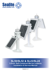
1
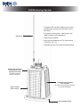
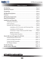
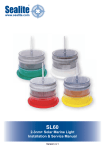
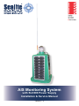
AIS Monitoring System
with SLC600 Power Supply
Installation & Service Manual
Version 1.0
AIS Monitoring System
•Complete AIS interface displaying accurate
positioning & operational information about
the AtoN
VHF aerial
• Low power consumption, making the units
ideal for solar AtoN installations
•Real time information
•IALA recommendations & ITU Publications
(ITU-R M. 1371-1)
•Operates on the VHF Maritime Mobile Band
Rotationally moulded
UV-stabilised virgin
polyethylene body
Provides excellent
impact-resistance
High visibility
IALA colours
4 x 20watt multicrystalline
solar modules
Ensures maximum light collection
to charge the battery
Internal 80Ah battery
AIS Monitoring System
Table of Contents
Introduction...........................................................................................Page 4
Operating Principle..............................................................................Page 4
Technology...........................................................................................Page 4
AIS Monitoring System........................................................................Page 5
Features................................................................................................Page 5
AIS System Components.....................................................................Page 6
About the AIS System..........................................................................Page 7
Installation and Assembly...................................................................Page 8
Unpacking Instructions.................................................................Page 8
Initial Inspection...........................................................................Page 8
Assembly with SLC600 Case.......................................................Page 8
• Installation of SL125 Lantern with Mounting Plate...........Page 8
• Installation of VHF Antenna..............................................Page 9
• Connection of Light, Antenna and GPS Cables...............Page 9
• Battery Connection.........................................................Page 10
• Testing Lantern Operation..............................................Page 10
How to Set-up and Program the AIS Unit.........................................Page 12
Programming the Remote AIS...................................................Page 12
Check Up-loaded Information....................................................Page 13
Testing the AIS Transmitter.......................................................Page 14
AIS Display Software.................................................................Page 15
Trouble Shooting................................................................................Page 16
Sealite Lantern Warranty...................................................................Page 18
Version No.
Description
Date
Approved
1.0
Manual Launch
4 August 2009
K. Paton
Latest products and information available at www.sealite.com.au
AIS Monitoring System
Introduction
Congratulations! By choosing to purchase a Sealite lantern you have become the
owner of one of the most advanced LED marine lanterns in the world.
Sealite Pty Ltd has been manufacturing lanterns for over 20 years, and particular care has been taken
to ensure your lantern gives years of service.
As a commitment to producing the highest quality products for our customers, Sealite has been
independently certified as complying with the requirements of ISO 9001:2000 quality management
system.
Sealite lanterns comply with requirements of the US Coast Guard in 33 CFR part 66 for Private Aids
To Navigation.
By taking a few moments to browse through this booklet, you will become familiar with the versatility of
your lantern, and be able to maximise its operating function.
Please remember to complete the Sealite warranty registration card accompanying your lantern.
Operating Principle
The solar module of the lantern converts sunlight to an electrical current that is used to charge the
battery. The battery provides power to operate the lantern at night.
The flasher unit has very low current requirements. A microprocessor drives an array of ultra bright
LED’s through a DC/DC converter, which enables the LED’s to operate within the manufacturer’s
specifications. The battery is protected from over-charging within the circuit to ensure maximum
battery life.
On darkness, the microprocessor will initiate a program check and after approximately 1 minute begin
flashing to the set code
Technology
Electronics
Sealite employs leading in-house electronic engineers in the design and development of software and
related circuitry. All individual electronic components are sourced directly by Sealite procurement staff
ensuring that only the highest quality components are used in our products.
LED Technology
All marine lanterns use the latest advancements in LED (Light Emitting Diode) technology as a
light source. The major advantage of LED’s over traditional light sources is well established in that
they typically have an operational life in excess of 100,000 hours, resulting in substantial savings to
maintenance and servicing costs.
Precision Construction
Commitment to investing in the design and construction of injection-moulded parts including optic
lenses, light bases and a range of other components ensures that all Sealite products are of a
consistent and superior quality.
Optical Performance
Sealite manufactures a range of marine LED lenses moulded from multi-cavity dies. Complex shapes
such as the SL70 lens are a testament to the company’s superior in-house lens manufacturing
capabilities and outstanding optical performance.
Award-winning, Patented Technology
Several United States and Australian patent registrations are held on Sealite’s range of innovative
designs, with other regional patents pending in Canada, United Kingdom and Europe.
Latest products and information available at www.sealite.com.au
AIS Monitoring System
AIS Monitoring System
The Automatic Identification System (AIS) is a broadcast system which operates in the VHF
maritime mobile band. It is capable of sending ship or AtoN (Aid to Navigation) information
such as identification, position, course, speed and more to other ships and to shore. A special
access technology is used to allow rapid update rates for multiple reports within the otherwise
limited capabilities of VHF.
Welcome now to the world of AIS monitoring. Our integration of AIS technology will provide
position and name data to your personal AIS station and to other authorized AIS users. All light
operational data is provided for your personal AIS station alone. Other optional data can be
made available such as meteorological information at your AtoN.
Tracking a drifting buoy or monitoring the status of a lantern has never been easier.
The Sealite AIS monitoring system is built around Sealite’s proven SL125 lantern. The robust
TeleBeacon-S® from Maritec provides full AIS functionality whilst the intuitive charting
software of ICAN completes the winning combination.
Features
•
Complete AIS interface displaying accurate positioning and operational information about the AtoN
•
Low power consumption, making the unit ideal for solar and AtoN installations
•
Real time information
•
Developed in accordance with IALA Recommendations and ITU Publications (ITU-R M. 1371-1)
•
Operates in the VHF Maritime Mobile Band
•
Enhances situational awareness
•
Reduces maintenance costs
Latest products and information available at www.sealite.com.au
AIS Monitoring System
AIS System Components
Figure 1: Automatic Identification System – SLC600 Case
Latest products and information available at www.sealite.com.au
AIS Monitoring System
About the AIS System
Sealite’s AIS AtoN (Automatic Identification System) operates in the international VHF Maritime Mobile
Band, enabling Port Authorities and other users to remotely monitor the real-time status of their AtoN
installation, whilst providing mariners in the broadcasting region crucial Message 21 information (as
defined by the international Telecommunications Union (ITU)) about the navigation aid.
The compact AIS AtoN TeleBeacon comes installed with Sealite’s range of SL125 products and interacts
with any AIS - enabled chart or radar screen, broadcasting information about the type and name of the
AtoN and GPS position.
In addition, the AIS AtoN broadcasts AIS Message 6 - enabling the operator to monitor the AtoN for solar
and battery voltage, flash setting and light status. Subject to the fitting of appropriate measuring devices,
meteorological data and a host of other parameters can be obtained via Message 8. This fixed frequency
telemetry unit operates on the designated AIS1 and AIS2 channels.
In technology partnership with Maritec Ltd, the AIS Telebeacon can be supplied integrated to the SL125
Type2 Complete or SLC600 power supply models - creating a completely integrated AIS - enabled
AtoN. Sealite’s AIS AtoN was developed in accordance with the International Association of Lighthouse
Authorities (IALA) Recommendations, and ITU Publications.
Figure 2: Automatic Identification System - Overview
Latest products and information available at www.sealite.com.au
AIS Monitoring System
Installation and Assembly Instructions
Installation of the AIS Monitoring System includes the following steps:•
Unpacking
•
Initial Inspection
•
Installing the AIS base unit (case)
•
Assembly
Unpacking instructions
Unpack all hardware and verify all components are in accordance with Figure 4, the SLC600 system.
Please contact your Sealite office if there is any hardware missing.
Initial Inspection
Inspect all hardware for damage. If there is any damage, please contact your Sealite Office. Retain
original packing material for possible future use in shipping the AIS Monitoring System.
Assembly with SLC600 Case
Assembly of the factory supplied SL125 AIS System requires the following:•
Installation of SL125 Lantern with mounting plate/GPS Antenna
•
Installation of VHF Antenna
•
Wiring of Lantern and Antennae
•
Installation & wiring of battery
•
Assembly of SLC500/600 Case
Installation of SL125 Lantern with Mounting Plate
Tools required:
1 x 6mm Allen Key
1 x Large Flat Blade Screwdriver
1 x Small Flat Blade Screwdriver
•
Remove the Flash Adjustment Plug from the base of the Lantern using the Large Flat Blade
Screwdriver. For details, please refer to the SL125 Installation Manual
•
Set the Flash Code and the Intensity using a Small screwdriver. For details of the Flash Codes
tables please refer to the SL125 Installation Manual.
•
Replace the Flash Adjustment Plug and secure tightly.
•
Remove the 4 x M8 Socket Head Cap Screws from the mounting plate on top of the SLC600 Solar
Housing.
•
Position the Sealite SL125 lantern on to the mounting plate. Remember to position the lantern with
the power cable exiting near the lantern power connector.
•
Secure the Lantern using the 4 x M8 Socket Head Cap Screws.
•
Remove the protective caps from both the Lantern and the Solar Panel Housing.
•
Connect the Lantern and secure tightly.
Latest products and information available at www.sealite.com.au
AIS Monitoring System
Installation of VHF Antenna
Tools required:
1 x 5mm Allen Key
1 x 10mm spanner or small wrench.
•
Remove the wing nut from the screw that is holding the antenna base plate in place.
•
Feed the antenna cable through the hole in the arm and position the antenna.
•
Secure the antenna using 3 x M6 Countersunk Cap Screws and Nylock nuts.
•
Remove the protective cap from the antenna plug on the Solar Panel Housing and connect the
antenna. Secure tightly.
Connection of Light, Antenna and GPS Cables
•
Remove the M8 Socket Head Cap Screws from the corners of the Solar Panel Housing.
•
With the help of an extra person, lift the SLC600 case off its base. Be careful when laying the
Housing over that you do not damage the Antenna, Lantern or Solar Panel.
•
Check the cable running from the GPS antenna, AIS antenna and SL125 Lantern are connected
connected to the AIS Telebeacon Case. See Fig 3 for details.
•
All connections are tested at Sealite before the product is packed.
Note: Do not fit the Solar Panel Housing until the battery is connected. See Battery Connection
section of this manual
Figure 3: Lantern & Antenna Cables
Latest products and information available at www.sealite.com.au
AIS Monitoring System
Battery Connection
Tools required:
1 x Allen Key, 6mm
2 x 10mm spanners or small adjustable wrenches.
1 x extra person for lifting.
The cover is already removed. (see Connection of light, Antenna and GPS Cables section of this
manual
•
Unscrew the 4 x Hand-Wheels from the corners of the Battery Box Lid.
•
Connect the Negative wire to the Negative Battery Terminal. Always connect Negative First!
•
Connect the Positive wire to the Positive Battery Terminal
•
Replace the Battery Box Lid and secure with the 4 x Hand-Wheels.
•
Replace the Solar Panel Housing and secure using the 4 x M8 Socket Head Cap Screws and
Washers.
Testing Lantern Operation
•
Place a dark towel or jacket over the lantern.
•
When the lantern detects darkness a Indicator LED on the circuit board will start flashing.
•
After 30 seconds of continual darkness the lantern will start operating.
For further information please refer to the Sealite SL125 Operator’s Manual.
Latest products and information available at www.sealite.com.au
10
AIS Monitoring System
Figure 4: Installation of SL125 Lantern and Antenna
No
Description
Qty
1
Sealite Lantern, SL125
1
2
M8 x 30mm Socket Head Cap Screw
4
3
M8 Spring Washer
8
4
M8 Penny Washer
8
5
AIS Antenna, (VHF)
1
6
M6 x 25mm Countersunk Cap Screw
3
7
M6 Flat Washer
3
8
M6 Nut
3
9
M8 x 40mm Socket Head Cap Screw
4
Fig 5: Mounting Hole Dimensions
Latest products and information available at www.sealite.com.au
11
AIS Monitoring System
How to Set-up and Program the AIS Unit
All AIS units will be supplied pre-programmed with the information supplied by the customer. This will
include both Latitude and Longitude and the unique Maritime Mobile Service Identity (MMSI) number.
The MMSI number is allocated by the relevent Maritime Safety Authority in each country.
The Sealite AIS uses a Maritec Telebeacon as the transmission source back to the base station.
Note: Programming of the AIS is only briefly outlined in this short note. For a full explanation of ALL
the required parameters refer to the Telebeacon-S, Operational and Technical Manual. Contact
Sealite for all information.
Programming the Remote AIS
Tools required:
1 x Laptop or PC with supplied “Utility” software loaded.
1 x RS232 cable and short adaptor cable (supplied) between PC Com Port and the 9 pin connector
located in the AIS enclosure.
•
Open the cover on the watertight box housing the AIS transmitter.
•
Connect the RS-232 cable to the and the RS-232 connector port located in the box
•
Apply 12V DC power to the AIS.
•
Run the “Utility” software. The window shown below will appear.
•
Select ‘Comport’ on the task bar and configure the PC to the appropriate Com port
(Com1, Com2, …)
•
Select “baud rate - 38400 - comport x”
•
Select “Own Profile” on the lower task bar. The window shown below will appear. Fill out the
required data fields including the allocated MMSI number.
•
Press ‘Write To TeleBeacon’
•
Wait for ‘Write’ to complete.
Latest products and information available at www.sealite.com.au
12
AIS Monitoring System
Check Up-loaded Information
•
Turn power OFF to the AIS unit;
•
Wait 5 seconds and turn power ON to the AIS unit;
•
Select the required Com Port - Baud Rate = 38400.
•
Select ‘Own Profile’, select ‘Read From TeleBeacon’
•
Wait for ‘Read’ to complete
•
The displayed window should show the previously data programmed into the Telebeacon
•
For full details refer to the complete TeleBeacon- S manual.
Latest products and information available at www.sealite.com.au
13
AIS Monitoring System
Testing the AIS Transmitter
Local Testing of the Remote AIS (Requires an appropriate AIS Receiver with an RS-232/USB output
and a PC connected to the receiver data output.
Do not place the AIS transmitter and receiver too close together. If this is not practical, use 50-Ohm
dummy antenna’s.
The AIS unit needs to be powered up and located outside to pick up the GPS signals required. The
unit will NOT operate if there is no GPS signal.
•
Connect the AIS unit to a PC or Laptop as above.
•
Select the required Com Port - Baud Rate = 38400.
•
Power the AIS and Sealite SL125 ON.
A graph similar to that shown below will begin to appear on the main screen window as shown below.
Clicking on each “DOT” on the screen will display the relevant message data.
Message 21
Data
Message 6
Data
(SL125 Beacon)
The AIS unit transmits Message 21, Message 6 and Message 8.
Transmission intervals are ultimately determined by the appropriate MMSI number allocated to each
unit.
For additional information refer to the Telecbeacon- S manual.
Latest products and information available at www.sealite.com.au
14
AIS Monitoring System
AIS Display Software
There are number of AIS software packages available to display vessel traffic and Aids to Navigation
data.
Your AIS receiving software package will need to be adapted to interpret Message 6 data that is
Sealite specific to the SL125 Beacon.
Presently the only software that has been written to accept the SL125 beacon data is ICAN Marine
Horizon Vista AIS package. For further information, please consult Sealite.
Latest products and information available at www.sealite.com.au
15
AIS Monitoring System
Trouble Shooting
Problem
Remedy
Lantern will not activate.
•
•
•
•
•
Timing codes will not change.
• Turn rotary switches several times to ensure contacts are clear.
Lantern will not operate for the
entire night.
• Expose lantern to direct sunlight and monitor operation for several days.
Sealite products typically require 1.5 hours of direct sunlight per day to
retain full autonomy. From a discharged state, the lantern may require
several days of operational conditions to ‘cycle’ up to full autonomy.
• Reducing the light output intensity or duty cycle (flash code) will reduce
current draw on the battery.
• Ensure solar module is clean and not covered by shading during the day.
Ensure lantern is in darkness.
Wait at least 60 seconds for the program to initialise in darkness.
Ensure switch setting is on a valid code (not unused flash code).
Ensure battery terminals are properly connected.
Ensure battery voltage is above 12volts.
All Sealite boards are fitted with two indicator LED’s. These are positioned near the Flash Code Rotary
Switches. Use the table below to help determine operational status.
LED Combinations
Lantern Status
Lantern
OFF
Normal
OFF
Normal running condition in
daylight.
Flashing
ON 0.1 seconds
OFF 0.1 seconds
OFF
Normal
ON
Normal running condition.
Flashing
ON 0.1 seconds
OFF 0.1 seconds
OFF
Normal
– synchronised
light
ON
Normal running condition but
lantern is not synchronised to GPSenabled lanterns.
Flashing
ON 1 second
OFF 1 second
OFF
Normal
– synchronised
light
ON
Normal running condition and
lantern is synchronised to GPSenabled lanterns.
YELLOW LED
RED LED
OFF
Comment
Fixed-on
Flat Battery (<8v)
OFF
Battery is flat. Battery must receive
charge (above 11.5v) and lantern
must see daylight for at least 1
minute before operation.
Flashing
ON 0.1 seconds
OFF 0.1 seconds
Low Battery
Voltage (<10.5v)
ON
Battery is low. Battery must receive
charge (above 11.5v) for at least 1
minute.
Fixed-on
OFF
High Battery
Voltage / Battery
Fully Charged
(>15v)
ON
Battery is charged.
Flashing
ON 1 second
OFF 0.2 seconds
Flashing
ON 1 second
OFF 0.2 seconds
Factory Setup
Mode
ON
Lantern’s in factory setup mode
(0xFF). Please change the flash
code.
Latest products and information available at www.sealite.com.au
16
AIS Monitoring System
Notes
Latest products and information available at www.sealite.com.au
17
AIS Monitoring System
Sealite Lantern Warranty V1.0
Activating the Warranty
Upon purchase, the Sealite Pty Ltd warranty must be activated for recognition of future claims. To do
this you have two (2) options:
1. Postal Registration
Please complete the Sealite Warranty Registration Card and return to Sealite within 30 days of
your purchase.
2. Online Registration
Please complete the Online Registration Form at;
www.sealite.com.au
Sealite Pty Ltd will repair or replace your lantern in the event of electronic failure for a period of
up to three years from the date of purchase.
The unit must be returned to Sealite freight prepaid.
Warranty Terms
1. Sealite Pty Ltd warrants that any Sealite marine products fitted with telemetry equipment including
but not limited to AIS, GSM, GPS or RF (“Telemetry Products”) will be free from defective
materials and workmanship under normal and intended use, subject to the conditions hereinafter
set forth, for a period of twelve (12) months from the date of purchase by the original purchaser.
2. Sealite Pty Ltd warrants that any BargeSafe™ Series of LED barge light products (“BargeSafe™
Products”) will be free from defective materials and workmanship under normal and intended use,
subject to the conditions hereinafter set forth, for a period of twelve (12) months from the date of
purchase by the original purchaser.
3. Sealite Pty Ltd warrants that any rotationally-moulded buoy products (“Buoy Products”) will be
free from defective materials and workmanship under normal and intended use, subject to the
conditions hereinafter set forth, for a period of twelve (12) months from the date of purchase by the
original purchaser.
4. Sealite Pty Ltd warrants that any Sealite marine products other than the Telemetry Products,
BargeSafe™ Products, and Buoy Products (“Sealite Products”) will be free from defective
materials and workmanship under normal and intended use, subject to the conditions hereinafter
set forth, for a period of three (3) years from the date of purchase by the original purchaser.
5. Sealite Pty Ltd will repair or replace, at Sealite’s sole discretion, any Telemetry Products,
BargeSafe™ Products, Buoy Products or Sealite Products found to be defective in material and
workmanship in the relevant warranty period so long as the Warranty Conditions (set out below)
are satisfied.
6. If any Telemetry Products, BargeSafe™ Products or Sealite Products are fitted with a
rechargeable battery, Sealite Pty Ltd warrants the battery will be free from defect for a period of
one (1) year when used within original manufacturer’s specifications and instructions.
Warranty Conditions
This Warranty is subject to the following conditions and limitations;
1. The warranty is applicable to lanterns manufactured from 1/1/2009.
2. The warranty is void and inapplicable if:
a. the product has been used or handled other than in accordance with the instructions in the
owner’s manual and any other information or instructions provided to the customer by Sealite;
b. the product has been deliberately abused, or misused, damaged by accident or neglect or in
being transported; or
c. the defect is due to the product being repaired or tampered with by anyone other than Sealite
or authorised Sealite repair personnel.
Latest products and information available at www.sealite.com.au
18
AIS Monitoring System
3. The customer must give Sealite Pty Ltd notice of any defect with the product within 30 days of the
customer becoming aware of the defect.
4. Rechargeable batteries have a limited number of charge cycles and may eventually need
to be replaced. Typical battery replacement period is 3-4 years. Long term exposure to high
temperatures will shorten the battery life. Batteries used or stored in a manner inconsistent with the
manufacturer’s specifications and instructions shall not be covered by this warranty.
5. No modifications to the original specifications determined by Sealite shall be made without written
approval of Sealite Pty Ltd.
6. Sealite lights can be fitted with 3rd party power supplies and accessories but are covered by the
3rd party warranty terms and conditions.
7. The product must be packed and returned to Sealite Pty Ltd by the customer at his or her
sole expense. Sealite Pty Ltd will pay return freight of its choice. A returned product must be
accompanied by a written description of the defect and a photocopy of the original purchase
receipt. This receipt must clearly list model and serial number, the date of purchase, the name and
address of the purchaser and authorised dealer and the price paid by the purchaser. On receipt
of the product, Sealite Pty Ltd will assess the product and advise the customer as to whether the
claimed defect is covered by this warranty.
8. Sealite Pty Ltd reserves the right to modify the design of any product without obligation to
purchasers of previously manufactured products and to change the prices or specifications of any
product without notice or obligation to any person.
9. Input voltage shall not exceed those recommended for the product.
10. Warranty does not cover damage caused by the incorrect replacement of battery in solar lantern
models.
11. This warranty does not cover any damage or defect caused to any product as a result of water
flooding or any other acts of nature.
Limitation of Liability
To the extent permitted by section 68A of the Trade Practices Act 1974 (Cth), the liability of Sealite
Pty Ltd under this Warranty will be, at the option of Sealite Pty Ltd, limited to either the replacement or
repair of any defective product covered by this Warranty.
Limited to Original Purchaser
This Warranty is for the sole benefit of the original purchaser of the covered product and shall not
extend to any subsequent purchaser of the product.
Miscellaneous
Apart from the specific warranties provided under this warranty, all other express or implied warranties
relating to the above product is hereby excluded to the fullest extent allowable under law. The warranty
does not extend to any lost profits, loss of good will or any indirect, incidental or consequential costs or
damages or losses incurred by the purchaser as a result of any defect with the covered product.
Warrantor
Sealite Pty Ltd has authorised distribution in many countries of the world. In each country, the
authorised importing distributor has accepted the responsibility for warranty of products sold by
distributor. Warranty service should normally be obtained from the importing distributor from whom you
purchased your product. In the event of service required beyond the capability of the importer, Sealite
Pty Ltd will fulfil the conditions of the warranty. Such product must be returned at the owner’s expense
to the Sealite Pty Ltd factory, together with a photocopy of the bill of sale for that product, a detailed
description of the problem, and any information necessary for return shipment.
Information in this manual is subject to change without notice and does not represent a commitment on the part of the vendor.
Sealite products are subject to certain Australian and worldwide patent applications.
Latest products and information available at www.sealite.com.au
19
AIS Monitoring System
Other Sealite Products Available
Marine Lanterns
(1-7nm)
Monitoring
& Control Systems
Bridge & Barge Lights
Marine Buoys
(up to 3mt in diameter)
Area Lighting
Mooring Systems
& Accessories
Head Office
USA Customers
Tel: +61 (0)3 5977 6128
Fax: +61 (0)3 5977 6124
Email: [email protected]
Internet: www.sealite.com.au
Tel: (603) 524-6066
Fax: (603) 524-8100
Email: [email protected]
Internet: www.sealiteusa.com
Sealite Pty Ltd
11 Industrial Drive
Somerville, Vic 3912
Australia
Sealite USA
29 Gilford East Drive
Gilford, NH 03249
USA
Latest products and information available at www.sealite.com.au
20