1
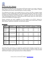
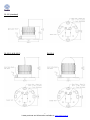
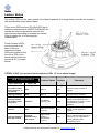
ISO9001:2000 Lic 14834 SAI Global Ltd SL125, SL125-GPS & SL125-C Installation and Service Manual Version 3.1 Table of Contents Introduction 2 Operating Principle 3 Technology 3 SL125 & SL125-C Models 4 GPS Option 8 Lantern Status 9 Maintenance & Servicing 11 Flash Codes 12 Troubleshooting 19 Sealite Lantern Warranty 20 Introduction Congratulations! By choosing to purchase a Sealite lantern you have become the owner of one of the most advanced LED marine lanterns in the world. Sealite Pty Ltd has been manufacturing lanterns for over 20 years, and particular care has been taken to ensure your lantern gives years of service. As a commitment to producing the highest quality products for our customers, Sealite has been independently certified as complying with the requirements of ISO 9001:2000 quality management system. Sealite lanterns comply with requirements of the US Coast Guard in 33 CFR part 66 for Private Aids To Navigation. By taking a few moments to browse through this booklet, you will become familiar with the versatility of your lantern, and be able to maximise its operating function. Please remember to complete the Sealite warranty registration card accompanying your lantern. 2 Latest products and information available at www.sealite.com.au Operating Principle The solar module of the lantern converts sunlight to an electrical current that is used to charge the battery (SL125-C models only). The battery provides power to operate the lantern at night. The flasher unit has very low current requirements. A microprocessor drives an array of ultra bright LED’s through a DC/DC converter, which enables the LED’s to operate within the manufacturer’s specifications. The battery is protected from over-charging within the circuit to ensure maximum battery life. On darkness, the microprocessor will initiate a program check and after approximately 1 minute begin flashing to the set code. Technology Electronics Sealite employs leading in-house electronic engineers in the design and development of software and related circuitry. All individual electronic components are sourced directly by Sealite procurement staff ensuring that only the highest quality components are used in our products. LED Technology All marine lanterns use the latest advancements in LED (Light Emitting Diode) technology as a light source. The major advantage of LED’s over traditional light sources is well established in that they typically have an operational life in excess of 100,000 hours, resulting in substantial savings to maintenance and servicing costs. Precision Construction Commitment to investing in the design and construction of injection-moulded parts including optic lenses, light bases and a range of other components ensures that all Sealite products are of a consistent and superior quality. Optical Performance Sealite manufactures a range of marine LED lenses moulded from multi-cavity dies. Complex shapes such as the SL70 lens are a testament to the company’s superior in-house lens manufacturing capabilities and outstanding optical performance. Award-winning, Patented Technology Several United States and Australian patent registrations are held on Sealite’s range of innovative designs, with other regional patents pending in Canada, United Kingdom and Europe. 3 Latest products and information available at www.sealite.com.au SL125 & SL125-C Models The SL125 5-7nm light fixture is the most advanced LED marine lantern on the market. Utilising the latest software and micro circuitry developments, the lantern boasts a huge number of features including flash-memory and the most efficient power conversion available. This maintenance-free model is also available with up to 4 tiers of 36 LEDs to increase the light intensity for a range of different light colours (see Specifications table below). Each LED tier utilises the Sealite omni directional LED Reflector (US Pat. No. 6,667,582. AU Pat. No. 778, 918) to increase the intensity and uniformity of the horizontal output. In particular, the SL125 4-tier model utilises a unique heat-dissipating domed lens to achieve maximum LED intensity output over a wider range of environmental conditions (see diagram page 5). Remote monitoring and control capabilities are also available for the SL125, allowing the performance of the units to be monitored from remote sites. System status includes battery condition, flash characters, operational configuration, and lantern/buoy position. Specifications · Model SL125-1 R SL125-1 G SL125-1 W SL125-1 Y SL125-2 R SL125-2 G SL125-2 W SL125-2 Y SL125-3 R SL125-3 G SL125-3 W SL125-3 Y SL125-4 R SL125-4 G SL125-4 W SL125-4 Y Intensity (peak) Colour No. LEDs Power Amp/hour Voltage 1-tier LED Lantern 87 86 136 65 Red Green White Yellow 36 36 36 36 0.42 0.32 0.32 0.42 12v 12v 12v 12v 2-tier LED Lantern 169 168 264 125 Red Green White Yellow 72 72 72 72 0.84 0.64 0.64 0.84 12v 12v 12v 12v 3-tier LED Lantern 252 249 387 182 Red Green White Yellow 108 108 108 108 1.26 0.96 0.96 1.26 12v 12v 12v 12v 4-tier LED Lantern 332 329 519 280 Red Green White Yellow 144 144 144 144 1.68 1.28 1.28 1.68 12v 12v 12v 12v Description · Specifications subject to change or variation without notice All SL125 models, outlined above, are available as a complete lantern assembly. Incorporating 1 or 2 20watt solar modules as standard, Sealite’s SL125-C provides a complete solution for visual navigation requirements. These models can also be readily equipped with up to 2 individual 40watt solar modules to power longer-range requirements or ancillary equipment. 4 Latest products and information available at www.sealite.com.au SL125 (standard) SL125-2 & SL125-3 SL125-4 5 Latest products and information available at www.sealite.com.au SL125-C Installation of SL125 & SL125-C Models Before activating the light, intensity and flash settings must be set. 1. Remove the bolt/lock securing the battery box lid, and open unit (SL125-C ONLY). 2. Remove the bung from the base of the SL125 light. 3. The power and range settings of the lantern are adjusted by setting the DIP switches inside the lantern. Your lantern is normally set to maximum range (see ‘Selecting Intensity Setting’, page 7). 4. Set rotary switches to the required flash code (see ‘Selecting a Flash Code’, page 7). 5. Replace bung. 6. A sealed vent on the base allows air transfer without moisture intake, and should not be disturbed. Lantern is activated by connecting positive and negative battery wires (and solar module wires for SL125-C). SL125 1. Battery Connection: Connect “Battery Positive (+)” wire to positive terminal of battery, and “Battery Negative (-)” wire to negative terminal of battery. Mains Connection: Connect positive and negative wires to 12volt power supply (ONLY). 2. To test place dark cover (towel or jacket) on top of light to activate sensor, light will come on. 3. Ensure that the unit is bolted to an even, flat surface. SL125-C 1. Inside the battery box is an internal battery container. To access the battery, remove the four screws and lid of this internal container. 2. Connect the “Battery Negative (-)” wire to the negative terminal of the battery, and the “Battery Positive (+)” wire to the positive terminal of the battery. 3. Connect the “Solar Negative (-)” wire to the negative terminal of the battery, and the “Solar Positive (+)” wire to the positive terminal of the battery. 4. Replace the internal battery container lid and screws making sure no wires are protruding. 5. Close the battery box lid and secure with bolt/lock. Light is now activated. 6. To test place dark cover (towel or jacket) on top of light to activate sensor, light will come on. 7. Ensure that the unit is bolted to an even, flat surface. Care must be taken to observe the polarity of each wire before they are connected. 6 Latest products and information available at www.sealite.com.au Selecting an Intensity Setting Pulse settings on Sealite lanterns operate via DIP switches, located near the rotary switches on the flasher unit. The pulse settings may be used to reduce the power consumption and intensity of the lantern. Setting the lantern to 25% pulse will reduce the power consumption to 25% of the normal 100% setting and the range by 50%. This setting may be used to adjust to local sunlight conditions. The following diagrams indicate pulse settings:- O N O N O N O N 1 2 1 2 1 2 1 2 100% 75% 50% 25% Selecting a Flash Code- Rotary Switches A and B All lanterns have 2 rotary switches marked A and B on the flasher unit, as below. Turning the small arrows to the appropriate number or letter will set the code (see ‘Flash Code’ section, page 12). The unit may take up to one minute to activate a new flash code. A comprehensive list of available flash codes is listed on pages 12-19 of this manual. Rotary Switches A and B B A NOTE: Refer to ‘Lantern Status’ section to check the status of the light after activated. Indicated by red and yellow status LED’s viewed at the base of the lens (page 9). 7 Latest products and information available at www.sealite.com.au GPS Option This GPS option can be added to any of the SL125 models previously outlined, and provides the user with the ability to mark a channel, port or river with independently operating lanterns that all flash in synchronisation. This improves the effectiveness of marker lights by highlighting the channel, port or river outline each time all the synchronised lights turn on. No additional power supplies, aerials or control systems are required, and with its microprocessorbased system, the SL125-GPS option is specifically designed to provide maximum reliability and performance over a wide range of environmental conditions. The GPS board is a separate PCB mounted above the standard SL125 circuitry. Operating Principle Each light operates independently and requires no operator intervention. A minimum of 3 satellites need to be in view for the built-in GPS receiver to collect time data. At dusk, the light sensor will turn the light on. If time data is available the light will come on synchronised to every other light with the same selected flash code. Synchronisation is achieved using an internal algorithm based on the highly accurate time base and time data received from the satellites. The satellite data is provided from a number of earth stations using atomic clocks as the time base. Continuous self-checking ensures that the light will continue to run in synchronisation. Light Activation At power-up the microprocessor checks that the internal GPS module is programmed correctly and is able to provide valid time base and time data. The light then checks for day/night. If it is daylight the internal microprocessor will go to idle mode after approximately 10 seconds. This reduces the overall power consumption when the light is not required. Once outside with a clear view of the sky, valid data should become available within 20 minutes. Daylight Operation During daylight hours the microprocessor is in idle mode to reduce power consumption. Time data continues to be updated once per second. The microprocessor will automatically exit the idle mode as soon as dark conditions are detected. Dark Operation When dark conditions are detected the light: Checks for valid time data and is turned on after a delay based on the current time and the length of the selected flash code; If valid time data is not detected the light will turn on after approximately 10 seconds. This light will not be synchronised. If the light turns on unsynchronised it will continually check for valid time data. Once valid data is found the light will automatically synchronise. NOTE: Lights will not synchronise if different flash codes are selected. 8 Latest products and information available at www.sealite.com.au Lantern Status Two status LED’s on the main printed circuit board (position A in image below) provide the operator with an indication of the lantern status. There is one RED and one YELLOW LED that in different combinations of ON/OFF/FLASHING will indicate the current operational status of the light,and vary depending on whether the lantern is set to steady-on, or a flashing light characteristic. These indicator LED’s can be viewed at the base of the lens. Separate indicator LEDs are located on the top of the GPS circuit board (where fitted- see position B & C of image below). STEADY LIGHT (see Lantern Status Indicator LEDs “A” from above image) LED Combinations YELLOW LED Lantern Status Lantern Comment RED LED Flashing ON/OFF very quick 9 times per second then 11 seconds off OFF Normal OFF Normal running condition in daylight. Flashing constant OFF Normal ON Normal running condition. Flashing ON/OFF very quick 9 times per second Fixed-on Low Battery Voltage (<8v) OFF Battery is flat. Battery must receive charge and light must see daylight for at least 1 minute before resuming normal operation. Fixed-on OFF High Solar Voltage (>15.3v) ON Battery is in state of very high charge. Check regulator if persists. Flashing ON/OFF 9 times per second Flashing ON/OFF 1 time per second High internal ambient temperature (>75°C) ON Internal ambient temperature is >75°C. Selected light intensity is dropped by 25%. Will resume normal operation when temperature <75°C. 9 Latest products and information available at www.sealite.com.au FLASHING LIGHT (Lantern Status Indicator LEDs “A” from image page 9) LED Combinations Lantern Status YELLOW LED Lantern Comment RED LED ON Normal running condition synchronised to GPS. Will take up to 10 minutes when first powered up. Condition only active in darkness.. OFF Normal but not synchronised ON Normal running condition, but light does not synchronise to other lights. GPS not fitted or no time data received. OFF Normal OFF Normal running condition in daylight. Flashing ON/OFF very quick 9 times per second Fixed-on Low Battery Voltage (<8v) OFF Battery is flat. Battery must receiver charge and light must see daylight for at least 1 minute before resuming normal operation. Fixed-on OFF High Solar Voltage (>15.3v) ON Battery is in state of very high charge. Check regulator if persists. Flashing ON/OFF 1 time per second Flashing ON/OFF 1 time per second High internal ambient temperature (>75°C) ON Internal ambient temperature is >75°C. Selected light intensity is dropped by 25%. Will resume normal operation when temperature <75°C. A. Flashing ON/OFF 1 time per second OFF Normal and synchronised when GPS fitted B. Flashing ON/OFF very quick constant C. Flashing ON/OFF very quick 9 times second then 11 seconds off NOTE 1. 1 second interval flashing Yellow LED indicates light is operating in synchronisation with the optional fitted GPS correctly. 2. If checking in daylight lantern must be covered to activate flash pattern. GPS BOARD (where fitted) LED Combinations YELLOW LED GPS Status Lantern Comment RED LED GPS Status Indicator LEDs “B” (see image page 9) A. ON steady OFF Normal ON or OFF GPS powered up. GPS Status Indicator LEDs “C” (see image page 9) B. Flashing ON/OFF very quick constant Flashing ON/OFF very quick constant faint Normal ON GPS software running. C. Flashes in sequence with red LED Flashes in sequence with yellow LED Off OFF/ON GPS software not operational 10 Latest products and information available at www.sealite.com.au Maintenance and Servicing Designed to be virtually maintenance-free, the SL125, SL125-C, & SL125-GPS require minimal attention, though the following maintenance and servicing information is provided to help ensure the life of your Sealite product. 1. Cleaning Lens- occasional cleaning of the light lens may be required. Using a cloth and warm soapy water, wipe off any foreign matter before rinsing the lens with fresh water. 2. Cleaning Solar Panels- occasional cleaning of the solar panels may be required. Using a cloth and warm soapy water, wipe off any foreign matter before rinsing the panels with fresh water (SL125-C models only). 3. Battery Check- inspection of batteries should be performed every three years (minimum) to ensure that the charger, battery and ancillary electronics are functioning correctly. Using a voltage meter, check that the battery voltage is at least 12 volts under 100MA load, and ensure all terminals are clear of foreign matter (SL125-C models only). Replacing the Battery The SL125-C lanterns have a sealed battery compartment, which provides the user with the ability to change the battery after years of operation. 1. Remove the bolt/lock securing the battery box lid, and open unit. 2. Inside the battery box is an internal battery container. To access the battery, remove the four screws and lid of this internal container. 3. Remove old battery from container and disconnect all connecting wires. Discard battery in a safe manner. 8. Connect the “Battery Negative (-)” wire to the negative terminal of the new battery, and the “Battery Positive (+)” wire to the positive terminal of the new battery. 9. Connect the “Solar Negative (-)” wire to the negative terminal of the battery, and the “Solar Positive (+)” wire to the positive terminal of the battery. 10. Replace the internal battery container lid and screws making sure no wires are protruding. 11. Close the battery box lid and secure with bolt/lock. Light is now activated. 12. To test place dark cover (towel or jacket) on top of light to activate sensor, light will come on. Care must be taken to observe the polarity of each wire before they are connected. To ensure waterproofing of the unit, make sure that no wires are protruding and that there is an even seal. Always discard old batteries in a safe manner. 11 Latest products and information available at www.sealite.com.au Flash Codes SEALITE® code reference is listed by number of flashes For the latest version of this document, check: http://www.sealite.com.au E-mail: [email protected] Symbols FL F Q VQ OC ISO LFL MO Flash followed by number Eg. FL 1 S, one flash every second Fixed Quick flash Very quick flash Occulting; greater period on than off Isophase; equal period on and off Long flash long Morse code ( ) contains letter For example, VQ (6) + LFL 10 S means 6 very quick flashes followed by a long flash, during a 10second interval. The amount of power your lantern draws through the night depends on the duty cycle, i.e. the amount of time on as a proportion to the timing cycle. For example, 0.5 seconds on and 4.5 seconds off equals a 10% duty cycle. It is best to operate at the lowest duty cycle appropriate to the actual needs of the application. Please note, Sealite models will retain full autonomy in normal operating conditions with duty-cycles up to approximately 30%. In applications whereby duty cycles exceed this limit, a reduction in lantern intensity is recommended. Please contact a Sealite consultant if assistance is required. Recommended Rhythm for Flashing Light - IALA Regions A and B MARK DESCRIPTION RHYTHM Port Hand & Starboard Marks: Any, other than Composite Group Flashing (2+1) Preferred Channel Starboard: Composite Group Flashing (2+1) Preferred Channel Port: Composite Group Flashing (2+1) North Cardinal Mark: Very quick or quick East Cardinal Mark: Very quick (3) every 5 seconds or quick (3) every 10 seconds South Cardinal Mark: Very quick (6) + long flash every 10 seconds or quick (6) + long flash every 15 seconds West Cardinal Mark: Very quick (9) every 10 seconds or quick (9) every 15 seconds Isolated Danger Mark: Group flashing (2) Safe Water Mark: Isophase, occulting, one long flash every 10 seconds or Morse Code “A” Special Marks: Any, other than those described for Cardinal, Isolated Danger or Safe Water Marks 12 Latest products and information available at www.sealite.com.au SWITCH A B 0 0 D 3 E 3 F 3 7 3 8 3 9 3 A 3 8 4 B 3 9 4 C 3 F 4 1 0 0 5 0 4 2 0 3 0 4 0 5 0 6 0 7 0 1 2 8 0 9 0 D 6 1 5 A 0 2 5 B 0 3 5 C 0 D 0 2 2 5 4 E 2 4 6 4 5 5 5 E 0 F 0 6 5 0 1 1 1 2 1 3 2 3 6 F 2 3 1 8 5 4 1 5 1 9 5 6 1 7 1 4 2 8 2 0 3 FLASH CODE ON OFF F (Steady light) VQ 0.5 S VQ 0.6 S VQ 0.6 S Q1S Q1S Q1S Q1S Q1S Q 1.2 S Q 1.2 S Q 1.2 S FL 1.5 S FL 1.5 S FL 1.5 S FL 1.5 S FL 2 S FL 2 S FL 2 S FL 2 S FL 2 S FL 2 S ISO 2 S FL 2.5 S FL 2.5 S FL 2.5 S FL 3 S FL 3 S FL 3 S FL 3 S FL 3 S FL 3 S FL 3 S ISO 3 S OC 3 S OC 3 S OC 3.5 S FL 4 S FL 4 S FL 4 S FL 4 S FL 4 S FL 4 S FL 4 S FL 4 S ISO 4 S OC 4 S OC 4 S FL 4.3 S FL 5 S FL 5 S FL 5 S FL 5 S FL 5 S FL 5 S ISO 5 S LFL 5 S OC 5 S 0.2 0.2 0.3 0.2 0.3 0.4 0.5 0.8 0.3 0.5 0.6 0.2 0.3 0.4 0.5 0.2 0.3 0.4 0.5 0.7 0.8 1.0 0.3 0.5 1.0 0.2 0.3 0.4 0.5 0.6 0.7 1.0 1.5 2.0 2.5 2.5 0.2 0.3 0.4 0.5 0.6 0.8 1.0 1.5 2.0 2.5 3.0 1.3 0.2 0.3 0.5 0.9 1.0 1.5 2.5 2.0 3.0 0.3 0.4 0.3 0.8 0.7 0.6 0.5 0.2 0.9 0.7 0.6 1.3 1.2 1.1 1.0 1.8 1.7 1.6 1.5 1.3 1.2 1.0 2.2 2.0 1.5 2.8 2.7 2.6 2.5 2.4 2.3 2.0 1.5 1.0 0.5 1.0 3.8 3.7 3.6 3.5 3.4 3.2 3.0 2.5 2.0 1.5 1.0 3.0 4.8 4.7 4.5 4.1 4.0 3.5 2.5 3.0 2.0 13 Latest products and information available at www.sealite.com.au SWITCH A B 1 3 2 3 C 6 B 5 C 5 8 1 9 1 A 1 7 5 B 1 5 2 9 2 6 4 3 3 4 3 A 4 9 6 5 6 D 5 C 1 E 5 B 4 6 2 A 2 6 6 B 2 F 5 C 4 7 6 0 6 1 6 D 1 2 6 E 1 1 4 C 2 D 2 7 2 2 4 8 6 5 3 6 3 F 1 D 4 3 4 0 2 4 4 7 4 A 6 E 4 FLASH CODE ON OFF OC 5 S OC 5 S FL 6 S FL 6 S FL 6 S FL 6 S FL 6 S FL 6 S FL 6 S FL 6 S ISO 6 S LFL 6 S OC 6 S OC 6 S OC 6 S FL 7 S FL 7 S OC 7 S FL 7.5 S FL 7.5 S FL 8 S FL 8 S ISO 8 S LFL 8 S OC 8 S LFL 8 S FL 9 S FL 9 S OC 9 S FL 10 S FL 10 S FL 10 S FL 10 S FL 10 S FL 10 S LFL 10 S LFL 10 S ISO 10 S LFL 10 S OC 10 S OC 10 S OC 10 S FL 12 S FL 12 S LFL 12 S FL 15 S LFL 15 S OC 15 S LFL 20 S FL 26 S 4.0 4.5 0.2 0.3 0.4 0.5 0.6 1.0 1.2 1.5 3.0 2.0 4.0 4.5 5.0 1.0 2.0 4.5 0.5 0.8 0.5 1.0 4.0 2.0 5.0 3.0 0.9 1.0 6.0 0.2 0.3 0.5 0.8 1.0 1.5 2.0 3.0 5.0 4.0 6.0 7.0 7.5 1.2 2.5 2.0 1.0 4.0 10.0 2.0 1.0 1.0 0.5 5.8 5.7 5.6 5.5 5.4 5.0 4.8 4.5 3.0 4.0 2.0 1.5 1.0 6.0 5.0 2.5 7.0 6.7 7.5 7.0 4.0 6.0 3.0 5.0 8.1 8.0 3.0 9.8 9.7 9.5 9.2 9.0 8.5 8.0 7.0 5.0 6.0 4.0 3.0 2.5 10.8 9.5 10.0 14.0 11.0 5.0 18.0 25.0 14 Latest products and information available at www.sealite.com.au SWITCH A B FLASH CODE ON OFF ON OFF 0 E 1 2 3 F 2 4 0 1 9 2 5 7 A 6 7 9 2 3 3 A 7 8 4 8 5 4 5 F 9 9 6 7 6 8 B 9 4 B C D A A 8 C D FL (2) 4 S VQ (2) 4 S FL (2) 4.5 S FL (2) 4.5 S FL (2) 4.5 S FL (2) 5 S FL (2) 5 S FL (2) 5 S FL (2) 5 S FL (2) 5 S Q (2) 5 S Q (2) 5 S FL (2) 5.5 S FL (2) 6 S FL (2) 6 S FL (2) 6 S FL (2) 6 S FL (2) 6 S FL (2) 6 S FL (2) 6 S Q (2) 6 S FL (2) 7 S FL (2) 8 S FL (2) 8 S FL (2) 8 S FL (2) 8 S FL (2) 8 S OC (2) 8 S OC (2) 8 S VQ (2) 8 S FL (2) 10 S FL (2) 10 S FL (2) 10 S FL (2) 10 S FL (2) 10 S FL (2) 10 S FL (2) 10 S FL (2) 10 S Q (2) 10 S FL (2) 12 S FL (2) 12 S FL (2) 12 S FL (2) 15 S FL (2) 15 S Q (2) 15 S FL (2) 20 S FL (2) 25 S 0.5 0.2 0.3 0.4 0.5 0.2 0.2 0.4 0.5 1.0 0.3 0.5 0.4 0.3 0.3 0.3 0.4 0.5 0.8 1.0 0.3 1.0 0.4 0.4 0.5 0.8 1.0 3.0 5.0 0.2 0.4 0.5 0.5 0.5 0.5 0.8 1.0 1.0 0.6 0.4 0.5 1.5 0.5 1.0 0.2 1.0 1.0 1.0 1.0 1.0 1.0 1.0 0.8 1.2 0.6 1.0 1.0 0.7 0.5 1.4 0.6 0.9 1.0 1.0 1.0 1.2 1.0 0.7 1.0 0.6 1.0 1.0 1.2 1.0 2.0 1.0 1.0 1.6 0.5 1.0 1.5 2.0 1.2 1.0 1.5 0.4 1.0 1.0 2.0 1.5 2.0 0.8 3.0 1.0 0.5 0.2 0.3 0.4 0.5 0.2 0.2 0.4 0.5 1.0 0.3 0.5 0.4 1.0 0.3 0.3 0.4 0.5 0.8 1.0 0.3 1.0 2.0 0.4 0.5 2.4 1.0 1.0 1.0 0.2 0.4 1.5 0.5 0.5 0.5 0.8 1.0 1.0 0.6 0.4 0.5 1.5 2.0 1.0 0.2 1.0 1.0 2.0 2.6 2.9 2.7 2.5 3.8 3.4 3.6 3.0 2.0 3.7 3.5 3.3 4.1 4.5 4.4 4.2 4.0 3.2 3.0 4.7 4.0 5.0 6.2 6.0 3.6 5.0 2.0 1.0 6.6 7.6 7.5 8.0 7.5 7.0 7.2 7.0 6.5 8.4 10.2 10.0 7.0 11.0 11.0 13.8 15.0 22.0 A B A A A 9 C A 7 7 B 9 A 8 A A A 9 8 7 9 9 B A 7 8 7 C C B A 8 7 7 9 7 9 7 9 A 9 9 8 7 B A A 15 Latest products and information available at www.sealite.com.au SWITCH A B 9 7 5 9 0 C E 9 3 C 2 B A B F A 0 B B 7 B 8 C 8 C B C 7 D B D 7 3 8 8 9 B B D 8 1 B E A E 7 B 6 4 8 5 8 1 8 F 7 9 D 0 8 F 8 0 9 1 9 6 8 1 C 4 B 3 B 5 B 6 B FLASH CODE ON OFF ON OFF ON OFF Q (3) 5 S VQ (3) 5 S VQ (3) 5 S VQ (3) 5 S FL (3) 6 S FL (2+1) 6 S Q (3) 6 S FL (3) 8 S FL (3) 9 S FL (3) 9 S FL (3) 10 S FL (3) 10 S FL (3) 10 S FL (3) 10 S FL (3) 10 S FL (3) 10 S FL (2+1) 10 S OC (3) 10 S Q (3) 10 S FL (2 + 1) 10 S FL (3) 12 S FL (3) 12 S FL (3) 12 S FL (3) 12 S FL (2+1) 12 S FL (2+1) 12 S FL (2+1) 13.5 S FL (3) 15 S FL (3) 15 S FL (3) 15 S FL (2+1) 15 S FL (2+1) 15 S FL (2+1) 15 S FL (2+1) 15 S VQ (3) 15 S FL (3) 20 S FL (3) 20 S FL (3) 20 S FL (3) 20 S 0.5 0.2 0.3 0.3 0.5 0.3 0.3 0.5 0.3 0.8 0.3 0.4 0.5 0.5 0.6 1.0 0.5 5.0 0.3 0.5 0.5 0.5 0.8 1.0 0.8 1.0 1.0 0.3 0.4 0.5 0.6 0.7 0.7 1.0 0.1 0.5 0.5 0.8 1.0 0.5 0.3 0.2 0.3 1.0 0.4 0.7 1.0 1.0 1.2 0.7 0.6 0.5 1.5 0.6 1.0 0.7 1.0 0.7 0.5 1.5 2.0 1.2 1.0 1.2 1.0 1.0 1.7 1.0 1.5 0.3 0.5 0.7 2.0 0.5 3.0 1.5 1.2 1.0 0.5 0.2 0.3 0.3 0.5 0.3 0.3 0.5 0.3 0.8 0.3 0.4 0.5 0.5 0.6 1.0 0.5 1.0 0.3 0.5 0.5 0.5 0.8 1.0 0.8 1.0 1.0 0.3 0.4 0.5 0.6 0.7 0.7 1.0 0.1 0.5 0.5 0.8 1.0 0.5 0.3 0.2 0.3 1.0 1.2 0.7 1.0 1.0 1.2 0.7 0.6 0.5 1.5 0.6 1.0 2.1 1.0 0.7 0.5 1.5 2.0 1.2 3.0 2.4 4.0 4.0 1.7 1.0 1.5 0.3 0.5 0.7 5.0 0.5 3.0 1.5 1.2 1.0 0.5 0.2 0.3 0.3 0.5 0.3 0.3 0.5 0.3 0.8 0.9 1.2 0.5 0.5 0.6 1.0 0.5 1.0 0.3 1.5 0.5 0.5 0.8 1.0 0.8 1.0 1.0 0.3 0.4 0.5 1.4 1.9 2.1 1.0 0.1 0.5 0.5 0.8 1.0 2.5 3.8 3.7 3.5 2.5 3.5 3.7 4.5 6.1 4.2 7.1 6.8 7.5 5.5 7.0 5.0 5.7 1.0 7.7 6.5 7.5 6.5 7.2 5.0 6.0 4.0 5.5 10.7 11.8 10.5 11.8 10.7 10.1 5.0 13.7 12.5 15.5 15.2 15.0 16 Latest products and information available at www.sealite.com.au SWITCH A B FLASH CODE ON OFF ON OFF ON OFF ON OFF B B 8 1 2 F B 4 C 3 A 4 8 7 D C 5 0 3 0 E 6 VQ (4) 4 S Q (4) 6 S Q (4) 6 S FL (4) 10 S FL (4) 10 S Q (4) 10 S FL (4) 12 S FL (4) 12 S FL (4) 12 S FL (4) 12 S Q (4) 12 S FL (4) 15 S FL (4) 15 S FL (4) 15 S FL (4) 16 S FL (4) 20 S FL (4) 20 S FL (4) 20 S FL (4) 20 S Q (4) 20 S Q (4) 28 S FL (4) 30 S 0.25 0.3 0.4 0.5 0.8 0.3 0.3 0.5 0.5 0.8 0.3 0.5 1.0 1.5 0.5 0.3 0.5 0.5 1.5 0.5 0.5 0.5 0.25 0.7 0.6 1.0 1.2 0.7 1.7 0.5 1.5 1.2 0.7 1.5 1.0 0.5 1.5 3.0 1.5 1.5 1.5 0.5 0.5 0.5 0.25 0.3 0.4 0.5 0.8 0.3 0.3 0.5 0.5 0.8 0.3 0.5 1.0 0.5 0.5 0.3 0.5 0.5 1.5 0.5 0.5 0.5 0.25 0.7 0.6 1.0 1.2 0.7 1.7 0.5 1.5 1.2 0.7 1.5 1.0 0.5 1.5 3.0 1.5 1.5 1.5 0.5 0.5 0.5 0.25 0.3 0.4 0.5 0.8 0.3 0.3 0.5 0.5 0.8 0.3 0.5 1.0 0.5 0.5 0.3 0.5 0.5 1.5 0.5 0.5 0.5 0.25 0.7 0.6 1.0 1.2 0.7 1.7 0.5 1.5 1.2 0.7 1.5 1.0 0.5 1.5 3.0 1.5 4.5 1.5 0.5 0.5 0.5 0.25 0.3 0.4 0.5 0.8 0.3 0.3 0.5 0.5 0.8 0.3 0.5 1.0 0.5 0.5 0.3 0.5 0.5 1.5 0.5 0.5 0.5 2.25 2.7 2.6 5.0 3.2 6.7 5.7 8.5 5.5 5.2 8.7 8.5 8.0 10.5 9.5 9.8 13.5 10.5 9.5 16.5 24.5 26.5 F D D D D E E F E D D D E D E D D D F F E F 17 Latest products and information available at www.sealite.com.au SWITCH A B FLASH CODE ON OFF ON OFF ON OFF ON OFF ON OFF D E E 5 9 9 Q (5) 7 S Q (5) 10 S FL (5) 16.5 S FL (5) 20 S FL (5) 20 S FL (5) 20 S 0.3 0.3 5.0 0.5 0.8 1.0 0.7 0.7 1.5 0.5 1.2 1.0 0.3 0.3 0.5 0.5 0.8 1.0 0.7 0.7 1.5 0.5 1.2 1.0 0.3 0.3 0.5 0.5 0.8 1.0 0.7 0.7 1.5 0.5 1.2 1.0 0.3 0.3 0.5 0.5 0.8 1.0 0.7 0.7 1.5 0.5 1.2 1.0 0.3 0.3 0.5 0.5 0.8 1.0 2.7 5.7 3.5 15.5 11.2 11.0 D D 8 F F E SWITCH A B F D A F 7 F A E FLASH CODE ON OFF ON OFF ON OFF ON OFF ON OFF ON OFF Q (6) 10 S FL (6) 15 S FL (6) 15 S FL (6) + LFL 15 S 0.3 0.3 0.5 0.5 0.7 0.7 1.0 1.0 0.3 0.3 0.5 0.5 0.7 0.7 1.0 1.0 0.3 0.3 0.5 0.5 0.7 0.7 1.0 1.0 0.3 0.3 0.5 0.5 0.7 0.7 1.0 1.0 0.3 0.3 0.5 0.5 0.7 0.7 1.0 1.0 0.3 0.3 0.5 0.5 4.7 9.7 7.0 7.0 SWITCH A B 6 E 7 E 2 F 2 E 3 E 8 F FLASH CODE ON OFF ON OFF ON OFF ON OFF ON OFF ON OFF ON OFF VQ (6) + LFL 10 S VQ (6) + LFL 10 S Q (6) + LFL 15 S Q (6) + LFL 15 S Q (6) + LFL 15 S VQ (6) + LFL 15 S 0.2 0.3 0.2 0.3 0.6 0.3 0.3 0.3 0.8 0.7 0.6 0.3 0.2 0.3 0.2 0.3 0.6 0.3 0.3 0.3 0.8 0.7 0.6 0.3 0.2 0.3 0.2 0.3 0.6 0.3 0.3 0.3 0.8 0.7 0.6 0.3 0.2 0.3 0.2 0.3 0.6 0.3 0.3 0.3 0.8 0.7 0.6 0.3 0.2 0.3 0.2 0.3 0.6 0.3 0.3 0.3 0.8 0.7 0.6 0.3 0.2 0.3 0.2 0.3 0.6 0.3 0.3 0.3 0.8 0.7 0.6 0.3 2.0 2.0 2.0 2.0 2.0 2.0 5.0 4.4 7.0 7.0 5.8 9.4 SWITCH A B 4 E 5 E 1 F 0 E 1 E FLASH CODE ON OFF ON OFF ON OFF ON OFF ON OFF ON OFF ON OFF ON OFF ON OFF VQ (9) 10 S VQ (9) 10 S Q (9) 15 S Q (9) 15 S Q (9) 15 S 0.2 0.3 0.2 0.3 0.6 0.3 0.3 0.8 0.7 0.6 0.2 0.3 0.2 0.3 0.6 0.3 0.3 0.8 0.7 0.6 0.2 0.3 0.2 0.3 0.6 0.3 0.3 0.8 0.7 0.6 0.2 0.3 0.2 0.3 0.6 0.3 0.3 0.8 0.7 0.6 0.2 0.3 0.2 0.3 0.6 0.3 0.3 0.8 0.7 0.6 0.2 0.3 0.2 0.3 0.6 0.3 0.3 0.8 0.7 0.6 0.2 0.3 0.2 0.3 0.6 0.3 0.3 0.8 0.7 0.6 0.2 0.3 0.2 0.3 0.6 0.3 0.3 0.8 0.7 0.6 0.2 0.3 0.2 0.3 0.6 5.8 4.9 6.8 6.7 4.8 SWITCH FLASH CODE ON A B MORSE CODE ( ) INDICATES LETTER 7 8 MO (A) 6 S 0.3 7 B MO (A) 8 S 0.4 8 8 MO (A) 8 S 0.8 B 8 MO (U) 10 S 0.3 C 8 MO (U) 10 S 0.4 D 8 MO (U) 10 S 0.5 9 8 MO (A) 10 S 0.5 8 9 MO (D) 10 S 5.0 A 8 MO (A) 15 S 0.5 F 8 MO (U) 15 S 0.6 0 9 MO (U) 15 S 0.7 1 9 MO (U) 15 S 0.7 7 D MO (B) 15 S 1.5 OFF ON OFF 0.6 0.6 1.2 0.7 0.6 0.5 0.5 1.0 1.5 0.3 0.5 0.7 0.5 1.0 2.0 2.4 0.3 0.4 0.5 1.5 1.0 2.0 0.6 0.7 0.7 0.5 4.1 5.0 3.6 0.7 0.6 0.5 7.5 1.0 11.0 0.3 0.5 0.7 0.5 ON OFF 0.9 1.2 1.5 7.1 6.8 6.5 1.0 1.0 1.4 1.9 2.1 0.5 11.8 10.7 10.1 0.5 ON OFF 0.5 10.5 18 Latest products and information available at www.sealite.com.au Trouble Shooting Problem Remedy Lantern will not activate. Timing codes will not change. Lantern will not operate for the entire night. • Ensure lantern is in darkness. • Wait at least 60 seconds for the program to initialise in darkness. • Ensure switch setting is on a valid code (not unused flash code). • Ensure battery terminals are properly connected. • Ensure battery voltage is above 12volts. • Turn rotary switches several times to ensure contacts are clear. • Expose lantern to direct sunlight and monitor operation for several days. Sealite products typically require 1.5 hours of direct sunlight per day to retain full autonomy. From a discharged state, the lantern may require several days of operational conditions to 'cycle' up to full autonomy. • Reducing the light output intensity or duty cycle (flash code) will reduce current draw on the battery. • Ensure solar module is clean and not covered by shading during the day. 19 Latest products and information available at www.sealite.com.au Sealite Lantern Warranty Activating the warranty Upon purchase, the Sealite warranty must be activated for recognition of future claims. To do this you have two (2) options: 1. Postal registration - Please complete the Sealite Warranty Registration card and return to Sealite within 30 days of your purchase. 2. Online registration - Please complete the Online Registration form at; www.sealite.com.au or www.sealiteusa.com Sealite Pty. Ltd. will repair or replace your lantern in the event of electronic failure for a period of three years from the date of purchase. The unit must be returned to Sealite Pty. Ltd. freight prepaid. Warranty Conditions 1. The warranty is applicable to lanterns manufactured from 1/1/2000. 2. The lantern must be installed in accordance with Sealite instructions. 3. No modifications to the original specifications determined by Sealite shall be made without written approval of Sealite Pty. Ltd. 4. Input voltage shall not exceed those recommended for the product. 5. Warranty does not cover damage caused by the incorrect replacement of battery in the SL15, SL60 or SL70 lantern models. 6. Replacement of battery is excluded from the warranty. 7. No recognition shall be given to flooding, or damage incurred from misuse of lanterns. 8. Solar modules are covered by individual manufacturers’ warranty. Information in this manual is subject to change without notice and does not represent a commitment on the part of the vendor. Sealite products are subject to certain Australian and world-wide patent applications. Head Office USA Customers: Sealite Pty Ltd 11 Industrial Drive Somerville, Vic 3912 Australia Tel: +61 3 5977 6128 Fax: +61 3 5977 6124 Email: [email protected] Internet: www.sealite.com.au GulfRim Navigation 1401 South State Abbeville, LA 70510 USA Ph: 877-893-0789 Fax: 337-893-6256 Internet: www.gulfrim.com Email: [email protected] 20 Latest products and information available at www.sealite.com.au


![Installation Manual [PDF 1 MB]](http://vs1.manualzilla.com/store/data/006009522_1-0fe6fa9acd9b0e1f3e4900405e8b6ec3-150x150.png)

![Installation Manual [PDF 4.6 MB]](http://vs1.manualzilla.com/store/data/006008736_1-137b4e33f3bd3f098e11b56c54272240-150x150.png)
![Installation Manual [PDF 3.1 MB]](http://vs1.manualzilla.com/store/data/006000040_1-a740b84bcdd0f591a4a671097fdfa72a-150x150.png)