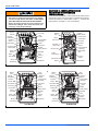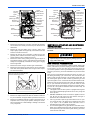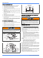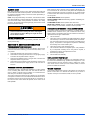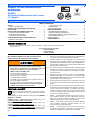
1
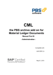
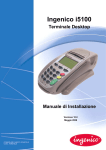
USER’S INFORMATION
MANUAL
EFFICIENCY
RATING
CERTIFIED
MODELS:
All Residential Multi-position Gas Furnaces
(33” Models)
ISO 9001
Certified Quality
Management System
TABLE OF CONTENTS
SAFETY . . . . . . . . . . . . . . . . . . . . . . . . . . . . . . . . . . . . . . . . . . . . . . . . 1
CONTACT INFORMATION . . . . . . . . . . . . . . . . . . . . . . . . . . . . . . . 1
INSTRUCTIONS FOR EXAMINING THE FURNACE
INSTALLATION . . . . . . . . . . . . . . . . . . . . . . . . . . . . . . . . . . . . . . . . . . 2
START-UP AND SHUTDOWN INSTRUCTIONS . . . . . . . . . . . . . . . . 3
HOW YOUR GAS FURNACE WORKS . . . . . . . . . . . . . . . . . . . . . . 3
OPERATING INSTRUCTIONS . . . . . . . . . . . . . . . . . . . . . . . . . . . . . 3
TO TURN OFF THE APPLIANCE . . . . . . . . . . . . . . . . . . . . . . . . . . 3
FURNACE MAINTENANCE - USER INFORMATION . . . . . . . . . . . . 4
EXTERNAL AIR FILTERS . . . . . . . . . . . . . . . . . . . . . . . . . . . . . . . . 4
How to Clean your Filter . . . . . . . . . . . . . . . . . . . . . . . . . . . . . . . . .4
BLOWER CARE . . . . . . . . . . . . . . . . . . . . . . . . . . . . . . . . . . . . . . . .4
MOTOR LUBRICATION . . . . . . . . . . . . . . . . . . . . . . . . . . . . . . . . . .4
SERVICE INFORMATION . . . . . . . . . . . . . . . . . . . . . . . . . . . . . . . . . .5
TROUBLESHOOTING PROBLEMS . . . . . . . . . . . . . . . . . . . . . . . . .5
FURNACE CONTROL DIAGNOSTICS . . . . . . . . . . . . . . . . . . . . . . .5
FURNACE MAINTENANCE - DEALER/CONTACTOR . . . . . . . . . . .5
REPLACEMENT PARTS LIST . . . . . . . . . . . . . . . . . . . . . . . . . . . . .5
WIRING DIAGRAM . . . . . . . . . . . . . . . . . . . . . . . . . . . . . . . . . . . . . . . .5
LIMITED WARRANTY . . . . . . . . . . . . . . . . . . . . . . . . . . . . . . . . . . . . .6
CONTACT INFORMATION
•
•
Go to website at www.york.com click on “contact”, then click on “contact form” and follow the instructions.
Contact us by mail:
Johnson Controls Unitary Products
Consumer Relations
5005 York Drive
Norman, OK 73069
We recommend that the user read all sections of this
manual and keep the manual for future reference.
1.
The furnace area must be kept clear and free of combustible materials, gasoline and other flammable vapors and liquids.
2.
FIRE OR EXPLOSION HAZARD - Failure to follow safety warnings
exactly could result in serious injury, death, or property damage.
— Do not store or use gasoline or other flammable vapors and
liquids in the vicinity of this or any other appliance.
— WHAT TO DO IF YOU SMELL GAS:
Insulating materials may be combustible. The furnace must be
kept free and clear of insulating materials. The furnace area must
be examined when installed in an attic or other insulated space or
when insulation is added to be sure that the insulation material has
been kept away from the furnace.
3.
•
•
The furnace needs air for combustion in order to operate properly
and safely. Do not block or obstruct air openings on the furnace,
air openings to the area where the furnace is installed, or spaces
around the furnace.
4.
Follow the instructions exactly as shown on the OPERATING
INSTRUCTION LABEL on the furnace or the “START-UP AND
SHUTDOWN INSTRUCTIONS” section of this manual when lighting the furnace or turning the furnace off.
5.
Should the gas supply fail to shut off or if overheating occurs, shut
off the gas valve to the furnace before shutting off the electrical
supply.
6.
Do not use this furnace if any part has been under water. A flooddamaged furnace is extremely dangerous. Attempts to use the furnace can result in fire or explosion. A qualified service agency
should be contacted to inspect the furnace and replace all gas
controls, control system parts, electrical parts that have been wet
or the furnace if deemed necessary.
7.
NEVER . . .Store flammable materials of any kind near your furnace. Gasoline, solvents, and other volatile liquids should be
stored only in approved containers outside your home. These
materials vaporize easily and are extremely dangerous.
8.
NEVER . . .Store cleaning materials near your furnace. Materials
such as bleaches, detergents, powdered cleansers, etc., can
cause corrosion of the heat exchangers.
9.
NEVER . . . Use the area around your furnace as a storage area
for items which could block the normal flow of air. This flow of air is
required for ventilation of the various furnace components.
Do not try to light any appliance.
Do not touch any electrical switch; do not use any phone (including cell phone) in your building.
• Leave the building immediately.
• Immediately call your gas supplier from a neighbor’s phone. Follow the gas supplier’s instructions.
• If you cannot reach your gas supplier, call the fire department.
— Installation and service must be performed by a qualified
installer, service agency or the gas supplier.
SECTION I: SAFETY
This is a safety alert symbol. When you see this symbol on
labels or in manuals, be alert to the potential for personal
injury.
Understand and pay particular attention to the signal words DANGER,
WARNING, or CAUTION.
DANGER indicates an imminently hazardous situation, which, if not
avoided, will result in death or serious injury.
WARNING indicates a potentially hazardous situation, which, if not
avoided, could result in death or serious injury.
CAUTION indicates a potentially hazardous situation, which, if not
avoided may result in minor or moderate injury. It is also used to
alert against unsafe practices and hazards involving only property damage.
356486-UUM-D-0608
356486-UUM-D-0608
SECTION II: INSTRUCTIONS FOR
EXAMINING THE FURNACE
INSTALLATION
FIRE OR EXPLOSION HAZARD
This furnace is designed and approved for use with Natural Gas and (LP) Propane Gas ONLY. DO NOT BURN
ANY LIQUID FUEL OR SOLID FUEL IN THIS FURNACE.
It is the owner’s responsibility to ensure that an annual inspection of the
entire heating portion of the unit is made by a qualified service agency.
Examine the furnace as outlined below in steps “1 - 8” before each
heating season. Use Figures 1 - 4 for visual reference.
Burning any unapproved fuel will result in damage to the
furnace heat exchanger, which could result in Fire, Personal Injury, and/or Property Damage.
Silicone
Tube
Vent Pipe
Flue
Collar
Induced
Draft Motor
Pressure
Switch
Induced Draft
Assembly
Gas Valve
Limit Switch
Ignitor
Electrical
Junction Box
Gas Valve
Electrical
Junction Box
Rollout
Safety Switch
Flame
Sensor
Manifold
Pipe
Control
Board
Safety
Door Switch
Blower
Capacitor
Rollout
Safety Switch
Flame Sensor
Manifold
Pipe
Ignitor
Limit Switch
Vent Pipe
Pressure
Switch
Manifold Draft
Assembly
Silicone Tube
Condensate
Pan
Safety
Door Switch
Control
Board
Transformer
Capacitor
Blower
Transformer
FIGURE 1: Component Location - 80% Single Stage Models
Flue
Collar
Pressure
Switch
Silicone
Tube
Induced
Draft Motor
Pressure
Sensor
Limit Switch
Induced Draft
Assembly
Pressure
Switch
Induced Draft
Assembly
Gas Valve
Limit Switch
Gas Valve
Ignitor
Rollout
Safety Switch
Flame
Sensor
Safety
Door Switch
Electrical
Junction Box
Manifold
Pipe
Flame
Sensor
Control
Board
Safety
Door Switch
Capacitor
Blower
Flue
Collar
Silicone
Tube
Induced
Draft Motor
Pressure
Sensor
Ignitor
Electrical
Junction Box
FIGURE 2: Component Location - 95% Single Stage Models
Transformer
Rollout
Safety Switch
Manifold
Pipe
Control
Board
Blower
Capacitor
Transformer
PSC MOTOR
ECM MOTOR
FIGURE 3: Component Location - 80% Modulating Models
2
Johnson Controls Unitary Products
356486-UUM-D-0608
Rollout
Safety Switch
Manifold
Pipe
Flame Sensor
Gas Valve
Ignitor
Limit Switch
(Behind gas valve)
Ignitor
Limit Switch
(Behind gas valve)
Vent Pipe
Draft Inducer
Assembly
Electrical
Junction Box
Pressure
Switch
Silicone Tube
Condensate
Pan
Safety
Door Switch
Vent Pipe
Draft Inducer
Assembly
Electrical
Junction Box
Pressure
Switch
Silicone Tube
Rollout
Safety Switch
Flame Sensor
Gas Valve
Manifold
Pipe
Condensate
Pan
Safety
Door Switch
Control
Board
Control
Board
Transformer
Transformer
Capacitor
Blower
Blower
PSC MOTOR
ECM MOTOR
FIGURE 4: Component Location - 97% Modulating Models
1.
Examine the heat exchanger, vent pipe, combustion air passages,
vent connectors and chimney to be sure they are clear and free of
obstructions.
2.
Examine the vent pipe making sure it is firmly in place, that it
slopes slightly upward and is physically sound without holes and
all of the connections are secure.
3.
Examine the return-air duct connections to make sure they are
physically sound, sealed to the furnace casing, and the ducts terminate outside the space containing the furnace.
4.
Examine the furnace casing making sure the physical support is
sound without sagging, cracks or gaps. Examine the furnace base
making sure it is physically sound without cracks, gaps or sagging
and has a good seal.
5.
Examine the furnace casing for obvious signs of deterioration.
6.
Examine the burner flames to make sure they are in good adjustment. Refer to the pictorial sketch shown in Figure 5 as a comparison to the actual flame.
Blue Cone Portion of Flame Should
Enter Heat Exchanger Tube
SECTION III: START-UP AND SHUTDOWN
INSTRUCTIONS
Read the Instructions Below Before Trying to Start the
Furnace!
If you do not follow these instructions exactly, a fire or
explosion may result causing property damage, personal
injury, and/or loss of life.
HOW YOUR GAS FURNACE WORKS
Your furnace is a very easy appliance to take for granted. Season after
season, it sits there in your home, keeping you warm and comfortable.
For this reason, you may never have given much thought to the way
your furnace operates. In order to get the safest and most efficient operation from your furnace, you should understand how your furnace does
its job.
When you set your thermostat to provide more heat in your home, you
are starting the heating cycle of the furnace. First, the inducer motor
starts to purge the heat exchanger of any remaining gases. Next, the
hot surface ignitor glows and after a warm-up period the gas valve
opens and ignition occurs. A short time later, the blower starts and distributes the warm air throughout the home. When the temperature setting on your thermostat is reached, the gas valve closes, the main
burners are turned off, and the blower continues to run until the remaining warm air in the system is distributed. When the blower stops, the
heating cycle has ended.
1.
This appliance does not have a pilot. It is equipped with an ignition
device which automatically lights the burner. Do not try to light the
burner by hand.
2.
BEFORE OPERATING; smell all around the appliance area for
gas. Be sure to smell next to the floor because some gas is
heavier than air and will settle on the floor.
3.
Use only your hand to push the gas control switch to the “on” position. Never use tools. If the switch will not operate by hand, don’t
try to repair it, call a qualified service technician. Force or
attempted repair may result in a fire or explosion.
4.
Do not use this appliance if any part has been under water. Immediately call a qualified service technician to inspect the appliance
and to replace any part of the control system and any gas control,
which has been under water.
FIGURE 5: Burner Flame Drawing (Upflow Configuration Shown)
7.
Examine and replace external air filters as needed to make sure
they are not blocked, and proper airflow is provided to the furnace.
8.
Examine any installed accessories or system components such as
evaporator coils to insure proper operation, drainage of condensate, and that there is no water leakage or damage to the furnace
or any components.
Johnson Controls Unitary Products
3
356486-UUM-D-0608
OPERATING INSTRUCTIONS
1.
STOP! Read the safety information above for your protection.
2.
Set the thermostat to the lowest setting in the heat mode.
3.
Turn off all electric power to the appliance.
4.
Remove furnace burner access panel/door.
5.
Move gas control switch to the “OFF” position. Do not force. See
Figures 6 & 7.
6.
Wait five (5) minutes to clear out any gas. If you then smell gas,
STOP! Follow “B” in the safety information above. If you don’t
smell gas, go to next step.
7.
Move gas control switch to the “ON” position. Do not force. See
Figures 6 & 7.
8.
Replace furnace burner access panel/door.
9.
Turn on all electric power to the appliance.
10. Set thermostat to the desired setting. Burner will light, which may
take 30-60 seconds.
External Manual
Shutoff Valve
Drip Leg
SECTION IV: FURNACE MAINTENANCE USER INFORMATION
Before proceeding, be sure the area is well ventilated. Turn
the thermostat OFF. If the blower is running, wait until it
stops automatically. Turn OFF the gas and electrical power
supplies to the furnace. Check all metal parts and surfaces
to be sure they have cooled to room temperature before
you begin.
TO TURN OFF THE APPLIANCE
Set the thermostat to lowest setting in heating mode.
2.
Turn off all electric power to the appliance if service is to be performed.
3.
Remove furnace burner access panel/door.
4.
Move gas control switch to the “OFF” position. See Figures 6 & 7.
5.
Replace furnace burner access panel/door.
Wrench
Boss
Inlet
Pressure
Port
Vent Port
FF
EXTERNAL AIR FILTERS
Filters used with this furnace must be installed external to the furnace
casing. DO NOT attempt to install filters inside the furnace cabinet.
Should overheating occur, or the gas valve fail to shut off,
turn the external manual gas valve in the gas supply line to
the furnace to the “off” position and let the furnace cool off
before shutting off the electrical power supply.
Outlet
Pressure
Port
Inlet
Grounded Joint Union
may be Installed
Inside or Outside Unit.
FIGURE 8: Gas Piping
11. After three (3) trials for ignition, if the appliance will not operate follow the instructions, “TO TURN OFF THE APPLIANCE” and call
your service technician or gas supplier.
1.
To Gas
Supply
To Gas
Supply
Outlet
O
N
Main Regulator
O
Adjustment
On/Off Switch
(Shown in ON position)
FIGURE 6: Single Stage Gas Valve
Some installations may have the air filter in a rack attached to the casing of the furnace or placed in the return air duct. If the filter location or
replacement process is not obvious, contact your installer or service
technician for assistance.
Every time the external air filters are changed the following items should
be visually inspected:
•
•
Check combustion air and vent pipe for blockage or leakage.
Check all components to be sure they are in good condition and
that there are no obvious signs of deterioration.
• Check the drain lines to make sure there are no cracks or leaks.
• Check for dirt or lint on any surfaces or on components. Do not try
to clean any of the surfaces or components. Cleaning of the furnace and its components must be done by a qualified service professional.
If during the inspection of your furnace, you find any of the following
conditions:
• Excessive amounts of dust and lint on components.
• Damaged or deteriorated components or surfaces.
• Leaks or blockage in the vent pipe passages.
• Water on any surface inside or outside of the furnace.
Do not operate the furnace, call a certified dealer or servicing contractor
to check or clean your furnace, or for more information if you have
questions about the operation of your furnace.
If all components appear to be in good operating condition, replace the
furnace access panels/doors. Turn ON the gas and electrical power
supplies to the furnace, and set thermostat to the desired temperature.
On/Off
Knob
Inlet
Pressure
Tap
Main
Regulator
Adjustment
Outlet
Pressure
Tap
How to Clean your Filter
High-velocity filters may be cleaned with a vacuum cleaner or washed
with a garden hose. Be sure to shake off excess water and allow filter to
completely dry before re-installing the filter.
Replace throw away filter(s) with the same size new filter(s). Throw
away filter(s) may be replaced with cleanable filter(s) at this time.
FIGURE 7: Modulating Gas Valve
4
Johnson Controls Unitary Products
356486-UUM-D-0608
BLOWER CARE
Even with good filters properly in place, blower wheels and motors will
become dust laden after months of operation. The entire blower assembly should be inspected annually. This service must be performed by a
qualified service agency.
NOTE: The spring-loaded safety cut-off switch, mounted at the blower
deck will automatically cut off the electrical power supply to the furnace
when the furnace blower access panel/door is removed. As a safety
precaution, all electrical power and the gas supply to the furnace should
be turned off before servicing.
Flash sequence codes 1 through 10 are as follows: LED will turn “on”
for 1/4 second and “off” for 1/4 second. This pattern will be repeated the
number of times equal to the code. For example, six “on” flashes equals
a number 6 fault code. All flash code sequences are broken by a 2 second “off” period.
SLOW GREEN FLASH: Normal operation.
DOUBLE AMBER FLASH: Normal heating operation - Modulating Furnace Models Only
SLOW AMBER FLASH: Normal operation with call for heat.
RAPID RED FLASHES: There is a problem with the operation of this
furnace. Contact your local dealer, contractor or service provider.
FURNACE MAINTENANCE - DEALER/CONTACTOR
Make sure you DO NOT move the clip on weight on the
indoor fan wheel when cleaning the wheel. This weight is
used to balance the wheel. Moving the weight will cause
the fan wheel to vibrate.
MOTOR LUBRICATION
The furnace should be cleaned and adjusted by a certified dealer or
qualified service contractor once a year or before the start of every
heating season. The following items must be cleaned and serviced or
replaced if there are signs of deterioration.
1.
The vent terminal.
2.
The furnace vent and combustion air intake passageways. Should
it be necessary to service the vent/air intake system, the manufacturer recommends this service be conducted by a qualified service
agency. The operation of this appliance requires the reassembly
and resealing of the vent/air intake system.
The motors in these furnaces are permanently lubricated, and do not
require periodic oiling.
SECTION V: SERVICE INFORMATION
TROUBLESHOOTING PROBLEMS
3.
The furnace burners, ignitor and flame sensor.
If your furnace is not operating correctly, the following visual checks
should be made before contacting your local contractor, dealer, or service provider.
4.
The condensate collection and disposal system. If any disassembly of components containing flue or vent gases is required, a
qualified service agency must perform the service.
1.
2.
5.
Heat exchanger assembly.
6.
Induced draft motor assembly.
3.
4.
Check that electrical power to the furnace is turned on.
Check that the manual gas shut-off valve in the gas piping supply
is turned to the ON position. Refer to Figure 8.
Check that the ON/OFF switch on the gas valve is turned to the
ON position. Refer to Figures 6 & 7.
Check that the furnace blower access panel/door is correctly positioned. The electrical power supply will be cut off if this door is
removed.
FURNACE CONTROL DIAGNOSTICS
The furnace has built-in, self-diagnostic capability. If a system problem
occurs, a blinking LED shows a fault code. The LED can flash red,
green or amber to indicate various conditions. It is located behind a
clear view port in the blower compartment door.
REPLACEMENT PARTS LIST
All components, assemblies, accessories, and replacement parts for
this furnace are available through qualified service agencies. It is not
recommended that the user purchase, install, or replace any components of this furnace. Contact your local contactor, dealer, or service
provider for additional information.
WIRING DIAGRAM
The unit wiring diagram may be found on the inside of one of the access
panels on the furnace. It is intended for reference only. If service is
required, contact your local contactor, dealer, or service provider.
The control continuously monitors its own operation and the operation
of the system. If a failure occurs, the LED will indicate the failure code. If
the failure is internal to the control, the light will stay on continuously. In
this case, the entire control should be replaced, as the control is not
field repairable.
Johnson Controls Unitary Products
5
Limited Warranty
UPG warrants this product to be free from defects in factory workmanship and material under normal use and service and will, at its option, repair or replace
any parts that prove to have such defects according to the terms outlined on this warranty. This warranty covers only the equipment described by the Product
Model Number and Serial Number listed on the Warranty Registration Card.
UPG warrants the primary heat exchangers in the product to be free from defects in factory workmanship and material under normal use and service and will at
its option, repair or furnish a replacement heat exchanger, either new or reconditioned, that meets the intended fit, use and function of the original heat
exchanger for any heat exchanger furnished by UPG which proves to have such defects within the duration of warranty coverage. Alternatively, UPG may, at its
option, extend a replacement allowance to be applied toward the purchase of a new furnace or packaged unit marketed by UPG. The exact amount of the
allowance will be determined at the discretion of UPG, based upon current market conditions, but in no case shall this allowance exceed thirty (30) percent of
the original consumer purchase price of the furnace, excluding such items as ductwork, wiring, piping and installation costs. UPG shall have no responsibility
hereunder for installation, shipping, handling or other charges except as specifically provided herein.
For your benefit and protection, return the Warranty Registration Card to UPG promptly after installation. This will initiate the warranty period and allow us to
contact you, should it become necessary. In the absence of a recorded Warranty Registration Card, the warranty period will begin upon product shipment from
UPG.
This warranty extends only to the original consumer purchaser and is non-transferable. For this warranty to apply, the product must be installed according to
UPG recommendations and specifications, and in accordance with all local, state, and national codes; and the product must not be removed from its place of
original installation. The warranty period for repair or replacement parts provided hereunder shall not extend beyond the warranty period stated on this warranty
HEAT EXCHANGER
FURNACE TYPE
Residential Applications
TG8S/TGLS/GG8S/GGLS
TM8M/TMLM/YM8M/YMLM/CM8M/CMLM/LM8M/LMLM &
TP8C/TPLC/YP8C/YPLC/CP8C/CPLC/LP8C/LPLC
TG9S/GG9S/TM9M/YM9M/CM9M/LM9M/TP9C/YP9C/CP9C/LP9C
Subsequent Owner
Non-Residential
Applications
PARTS
Original Owner
20
N/A
10
5
Lifetime
20
10
5
Lifetime
20
10
5
UPG strongly recommends regular periodic preventative maintenance on this equipment. The person most familiar with the equipment in your HVAC system is
a UPG dealer. The UPG dealer can ensure your maintenance program meets the conditions of the "UPG Warranty", maximize the efficiency of the equipment,
and service your unit within the mandated guidelines with regard to unlawful discharge of refrigerants into the atmosphere.
This warranty applies only to products installed in the United States and Canada.
EXCLUSIONS
This warranty does not cover any:
1.
Shipping, labor, or material charges.
2.
Damages resulting from transportation, installation, or servicing.
3.
Damages resulting from accident, abuse, fire, flood, alteration, or acts of God (tampering, altering, defacing or removing the product serial number will
serve to void this warranty).
4.
Damages resulting from use of the product in a corrosive atmosphere.
5.
Damages resulting from inadequacy or interruption of electrical service or fuel supply, improper voltage conditions, blown fuses, or other like damages.
6.
Cleaning or replacement of filters.
7.
Damages resulting from failure to properly and regularly clean air and/or water side of condenser and evaporator.
8.
Damages resulting from: (I) freezing of condenser water or condensate; (II) inadequate or interrupted water supply; (III) use of corrosive water; (IV) fouling
or restriction of the water circuit by foreign material or like causes.
9.
Damages resulting from operation with inadequate supply of air or water.
10. Damages resulting from use of components or accessories not approved by UPG (vent dampers, etc.).
11. Increase in fuel or electric cost.
THIS WARRANTY IS IN LIEU OF ALL OTHER WARRANTIES, EXPRESSED OR IMPLIED, INCLUDING THE IMPLIED WARRANTIES OF MERCHANTABILITY AND FITNESS FOR A PARTICULAR PURPOSE.
SOME STATES DO NOT ALLOW THE DISCLAIMER OF IMPLIED WARRANTY, SO THAT THE ABOVE DISCLAIMER MAY NOT APPLY TO YOU.
SOME STATES ALLOW ONLY A PARTIAL LIMITATION ON IMPLIED WARRANTIES TO LIMIT THE DURATION OF IMPLIED WARRANTIES TO THE DURATION OF THE EXPRESS WARRANTY. IN SUCH STATES, THE DURATION OF IMPLIED WARRANTIES IS HEREBY EXPRESSLY LIMITED TO THE DURATION OF THE EXPRESS WARRANTY ON THE FACE HEREOF.
IN NO EVENT, WHETHER AS A RESULT OF BREACH OF WARRANTY OR CONTRACT, TORT (INCLUDING NEGLIGENCE) STRICT LIABILITY OR OTHERWISE, SHALL UPG BE LIABLE FOR SPECIAL, INCIDENTAL, OR CONSEQUENTIAL DAMAGES, INCLUDING BUT NOT LIMITED TO LOSS OF USE OF
THE EQUIPMENT OR ASSOCIATED EQUIPMENT, LOST REVENUES OR PROFITS, COST OF SUBSTITUTE EQUIPMENT OR COST OF FUEL OR ELECTRICITY. THE ABOVE LIMITATIONS SHALL INURE TO THE BENEFIT OF UPG'S SUPPLIERS AND SUBCONTRACTORS. THE ABOVE LIMITATION ON
CONSEQUENTIAL DAMAGES SHALL NOT APPLY TO INJURIES TO PERSONS IN THE CASE OF CONSUMER GOODS.
SOME STATES DO NOT ALLOW THE EXCLUSION OR LIMITATION OF LIABILITY FOR CONSEQUENTIAL OR INCIDENTAL DAMAGES, OR FOR STRICT
LIABILITY IN TORT, SO THAT THE ABOVE EXCLUSIONS AND LIMITATIONS MAY NOT APPLY TO YOU.
UPG DOES NOT ASSUME, OR AUTHORIZE ANY OTHER PERSON TO ASSUME FOR UPG, ANY OTHER LIABILITY FOR THE SALE OF THIS PRODUCT.
THIS WARRANTY GIVES YOU SPECIFIC LEGAL RIGHTS. YOU MAY ALSO HAVE OTHER RIGHTS WHICH VARY FROM STATE TO STATE.
For Owner's Information:
PRODUCT MODEL. NO. ____________________ INSTALLATION DATE ______________________________
UNIT SERIAL NO. _________________________ INSTALLING DEALER ______________________________
Subject to change without notice. Printed in U.S.A.
Copyright © 2008 by Johnson Controls, Inc. All rights reserved.
Johnson Controls Unitary Products
5005 York Drive
Norman, OK 73069
356486-UUM-D-0608
Supersedes: 356486-UUM-C-0508